

PEERLESS PARAMOUNT PP740, Paramount PP740-S, PARAMOUNT PP240/BK, Paramount PWV240BK, Paramount PWV240 Installation And Assembly Manual
Page 1
Installation and Assembly:
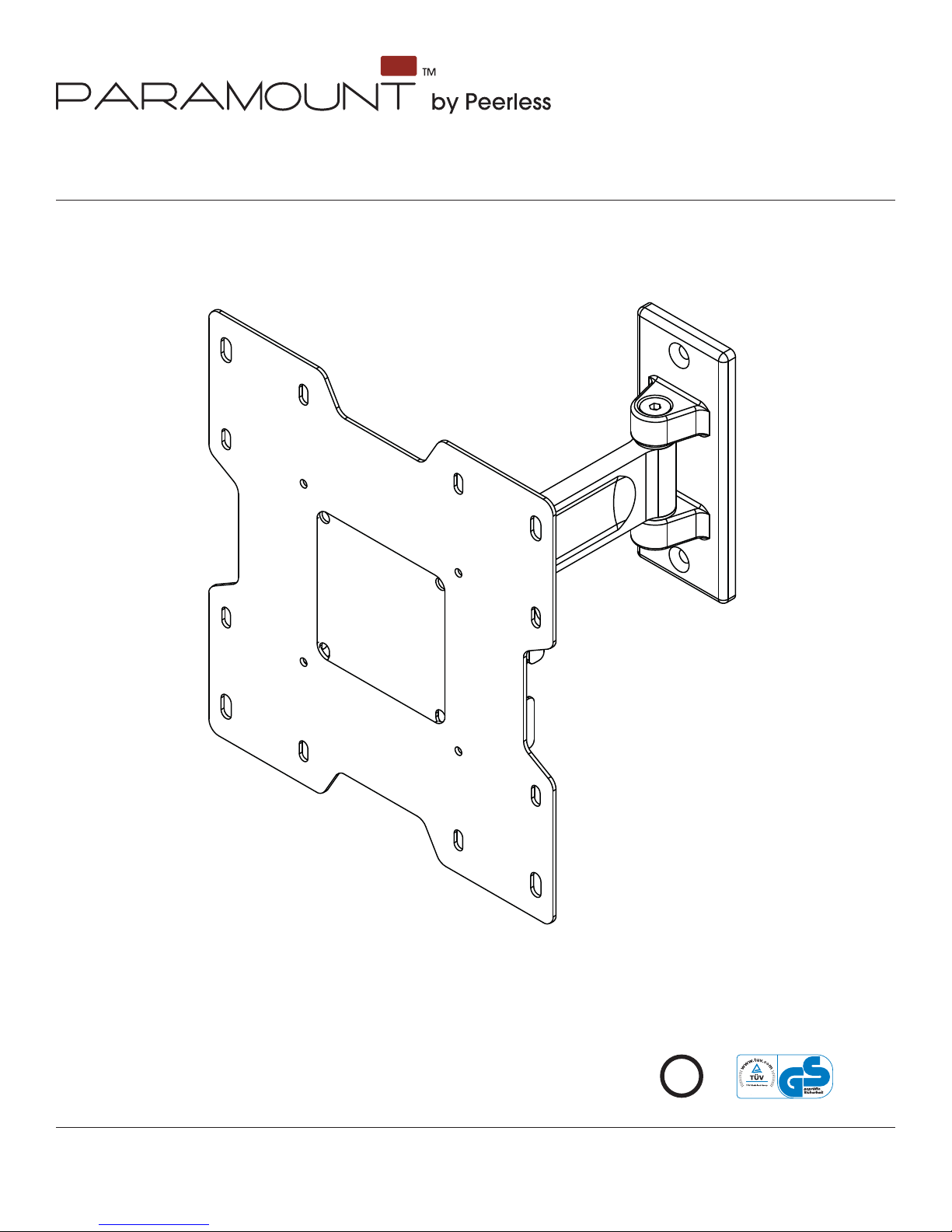
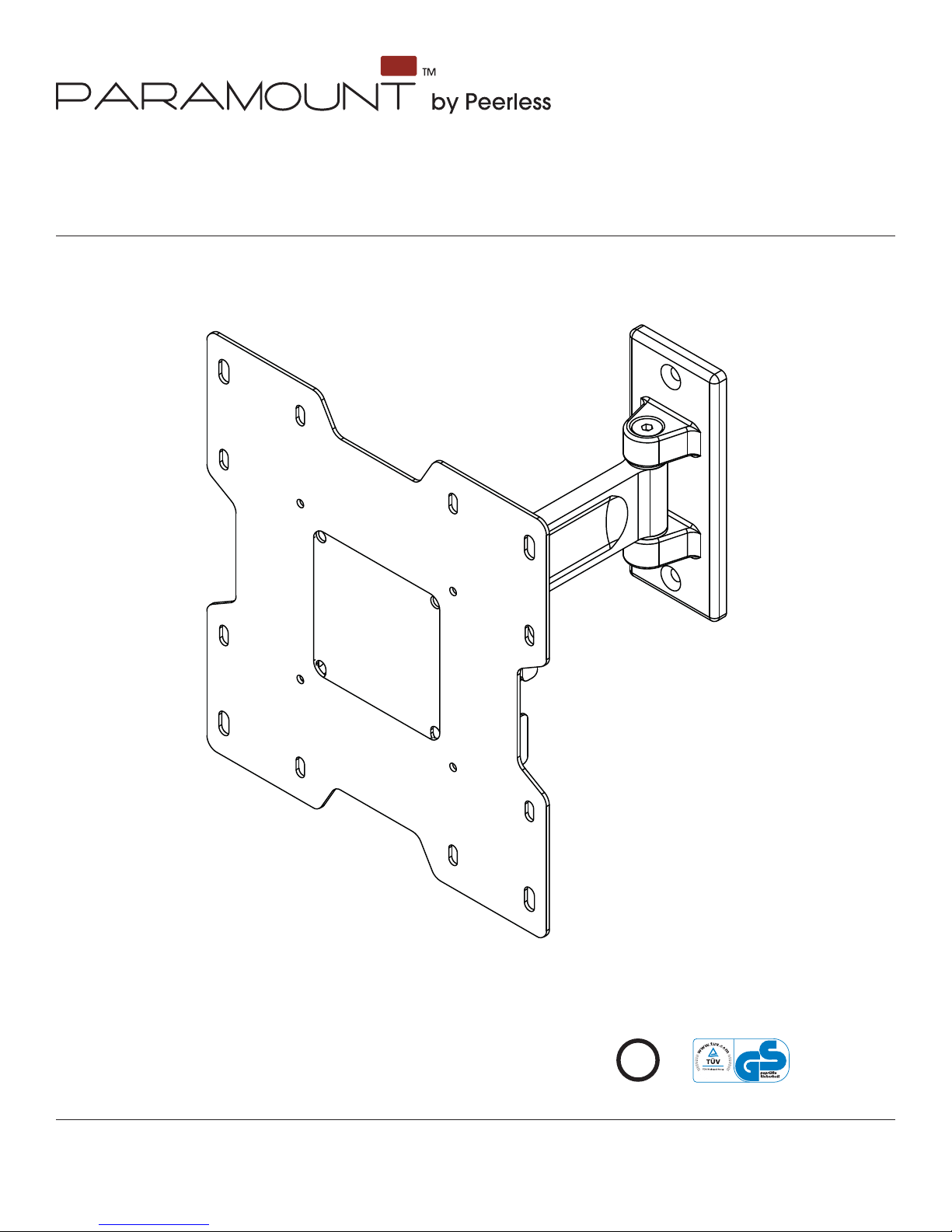
Paramount™ Pivot for 22" - 40" (56 - 102 cm) LCD screens
Models: PP740, PP740-S, PWV240/BK
Features:
• Fits 22" - 40" (56 - 102 cm) LCD screens
• Two tensionable pivot points for extensive adjustment of
viewing angle
• VESA® 75/100/200 x 100/200 x 200 compatible
• Frees up space by folding fl at against the wall
U
©
L
I
USC
D
2
:
6
0
7
0
8
0
1
0
0
Max Load Capacity: 80 lb (36 kg)
ISSUED: 01-15-08 SHEET #: 095-9282-2 06-12-09
Page 2
NOTE: Read entire instruction sheet before you start installation and assembly.
WARNING
• Do not begin to install your Peerless product until you have read and understood the instructions and warnings
contained in this Installation Sheet. If you have any questions regarding any of the instructions or warnings, for US
customers please call Peerless customer care at 1-800-865-2112, for all international customers, please contact
your local distributor.
• This product should only be installed by someone of good mechanical aptitude, has experience with basic building
construction, and fully understands these instructions.
• Make sure that the supporting surface will safely support the combined load of the equipment and all attached
hardware and components.
• Never exceed the Maximum Load Capacity. See page one.
• If mounting to wood wall studs, make sure that mounting screws are anchored into the center of the studs. Use of
an "edge to edge" stud fi nder is highly recommended.
• Always use an assistant or mechanical lifting equipment to safely lift and position equipment.
• Tighten screws fi rmly, but do not overtighten. Overtightening can damage the items, greatly reducing their holding
power.
• This product is intended for indoor use only. Use of this product outdoors could lead to product failure and personal
injury.
• This product was designed to be installed on the following wall construction only;
WALL CONSTRUCTION HARDWARE REQUIRED
x Wood Stud Included
x Wood Beam Included
x Solid Concrete Included
x Cinder Block Included
x Metal Stud Do not attach except with Peerless Metal Stud Accessory Kit
(not evaluated by UL)
x Brick Contact Qualifi ed Professional (not evaluated by UL)
x Other or unsure? Contact Qualifi ed Professional
Tools Needed for Assembly
• stud fi nder ("edge to edge" stud fi nder is recommended)
• phillips screwdriver
• drill
• 5/16" (8 mm) bit for concrete and cinder block wall
• 5/32" (4 mm) bit for wood stud wall
• level
Table of Contents
Parts List.................................................................................................................................................................................3
Installation to Wood Stud Wall ................................................................................................................................................5
Installation to Solid Concrete and Cinder Block .....................................................................................................................6
Attaching Adapter Plate to Screen with VESA® Mounting Pattern ..........................................................................................7
Installing to Peerless PLP Model Adapter Bracket .................................................................................................................8
Cord Management and Arm Tension Adjustment ................................................................................................................10
2 of 46
ISSUED: 01-15-08 SHEET #: 095-9282-2 06-12-09
Page 3
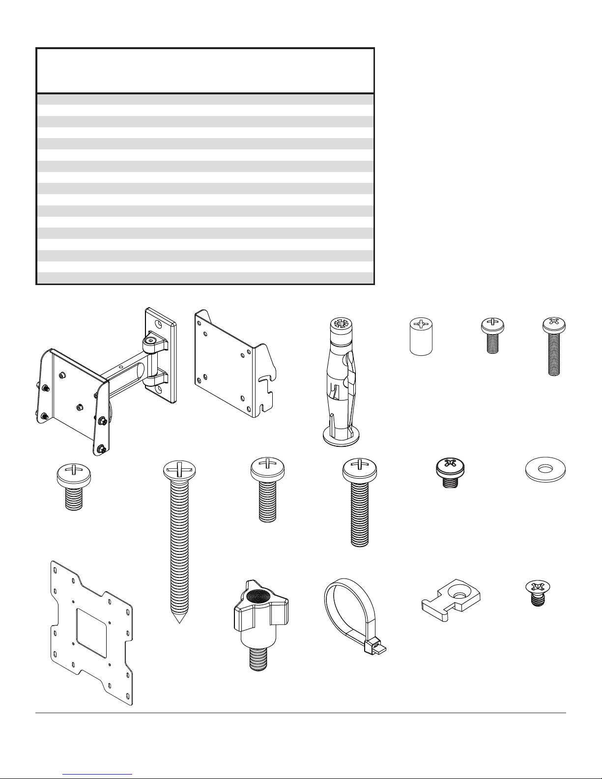
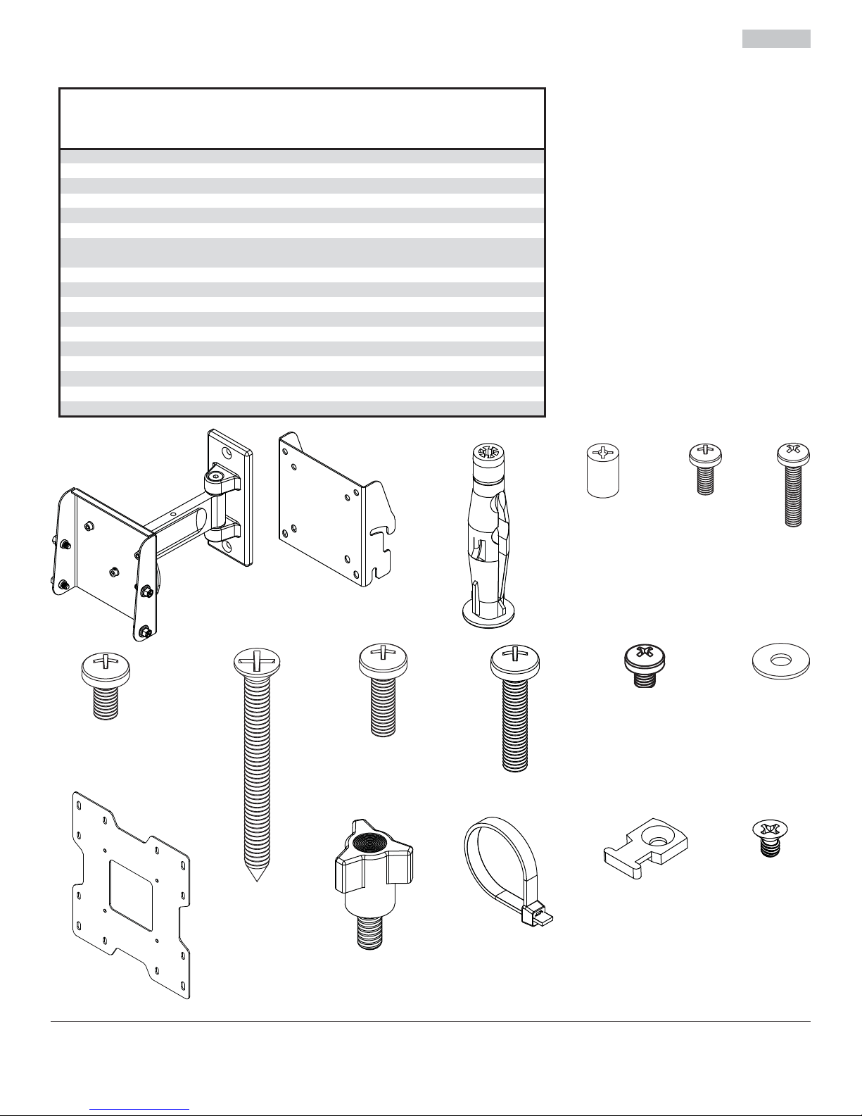
Before you begin, make sure all parts shown are included with your product.
K
A
Parts List
Description
wall mount assembly
concrete anchor 2 590-0320
B
retaining spacer 4 590-5005
C
M4 x 10 mm phillips screw 4 504-9012
E
M4 x 20 mm phillips screw 4 504-9020
F
M6 x 12 mm phillips screw 4 520-1128
G
#14 x 2.5" flat head wood screw 2 520-1202
H
M6 x 20 mm phillips screw 4 520-9402
I
M6 x 30 mm phillips screw 4 510-9109
J
M5 x 6 mm phillips screw 4 520-1023
K
#10 flat washer 4 540-9400
L
hook bracket 1
M
adapter plate
N
1/4-20 knob 1 560-1162
O
P cable tie 3 560-9711 560-2004
cable tie anchor 3 590-1290
Q
R 8-32 x 1/4" flat head screw 3 520-1622 520-2622
Parts may appear slightly different than illustrated.
A
PWV240/B
PP740
Part # Part #
Qty.
095-P1629 095-4629
1
095-P1561 095-4561
095-P1322 095-4322
1
M
PP740-S
590-0320
590-5003
520-2027
504-2014
520-2039
520-6165
520-2040
520-2042
520-2214
540-9442
560-1162
590-1290
BE
CF
G
N
H
IJ
O
P
3 of 46
ISSUED: 01-15-08 SHEET #: 095-9282-2 06-12-09
Q
K
L
R
Page 4
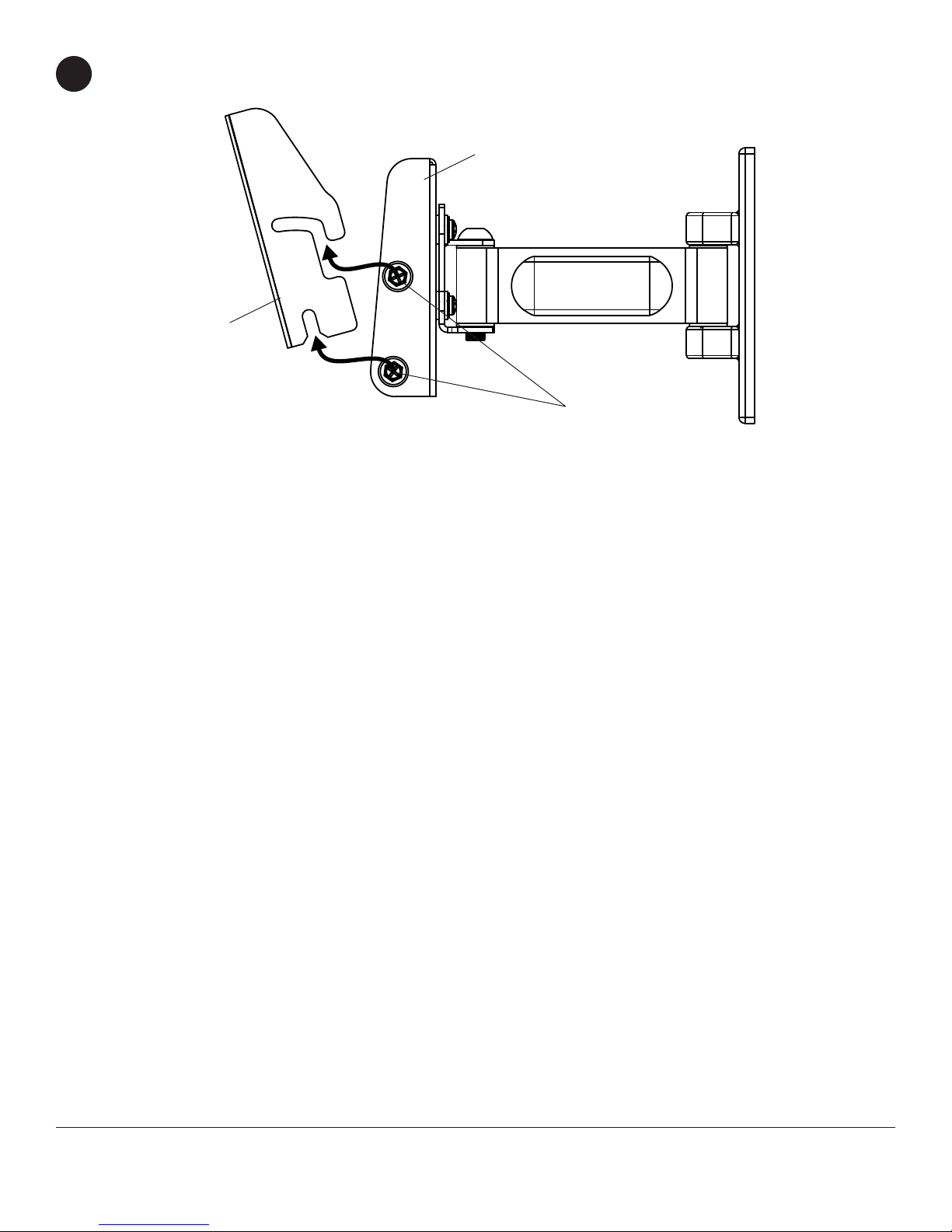
Loosen 1/4-20 x 1/2" screws to remove hook bracket (M) from wall mount assembly prior to installation.
1
A
M
1/4-20 X 1/2"
SCREWS
4 of 46
ISSUED: 01-15-08 SHEET #: 095-9282-2 06-12-09
Page 5
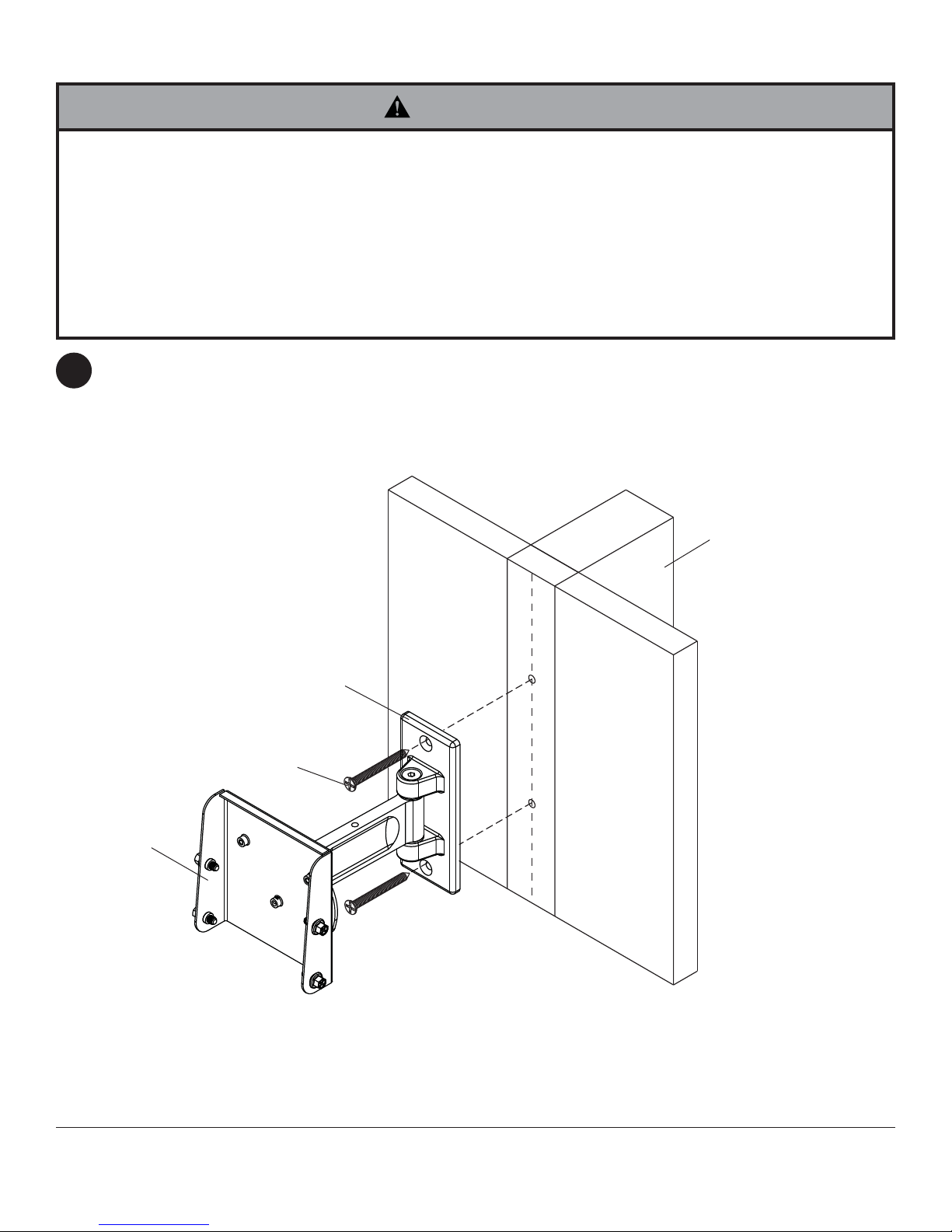
Installation to Wood Stud Wall
WARNING
• Installer must verify that the supporting surface will safely support the combined load of the equipment and all
attached hardware and components.
• Tighten wood screws so that wall plate is fi rmly attached, but do not overtighten. Overtightening can damage the
screws, greatly reducing their holding power.
• Never tighten in excess of 80 in. • lb (9 N.M.).
• Make sure that mounting screws are anchored into the center of the stud. The use of an "edge to edge" stud fi nder
is highly recommended.
• Hardware provided is for attachment of mount through standard thickness drywall or plaster into wood studs. Install-
ers are responsible to provide hardware for other types of mounting situations (not UL approved).
Using a stud fi nder, locate and mark the edges of the wood stud used in mounting this product. Use of an edge to
2
edge stud fi nder is highly recommended. Use a level to draw a vertical line down the center of the stud. Use wall
plate as template to mark center of holes along the vertical line. Drill two 5/32" (4 mm) dia. holes 2.5" (64 mm)
deep. Attach wall mount (A) to wall using two #14 x 2.5" fl at head wood screws (H) as shown.
Skip to step 3 on page 7.
A
WOOD STUD WALL
WALL PLATE
H
5 of 46
ISSUED: 01-15-08 SHEET #: 095-9282-2 06-12-09
Page 6
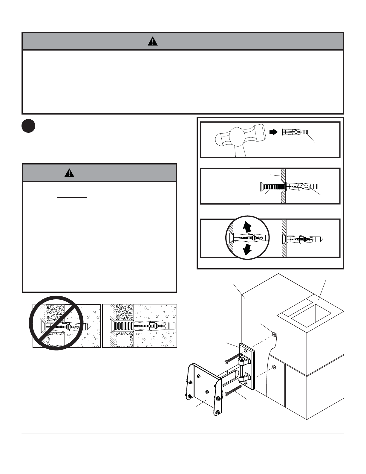
Installation to Solid Concrete and Cinder Block
WARNING
• When installing Peerless wall mounts on cinder block, verify that you have a minimum of 1-3/8" (35 mm) of actual
concrete thickness in the hole to be used for the concrete anchors. Do not drill into mortar joints! Be sure to mount
in a solid part of the block, generally 1" (25 mm) minimum from the side of the block. Cinder block must meet
ASTM C-90 specifi cations. It is suggested that a standard electric drill on slow setting is used to drill the hole
instead of a hammer drill to avoid breaking out the back of the hole when entering a void or cavity.
• Concrete must be 2000 psi density minimum. Lighter density concrete may not hold concrete anchor.
• Make sure that the supporting surface will safely support the combined load of the equipment and all attached
hardware and components.
Level and use wall plate as template to mark center
2
of holes. Drill two 5/16" (8 mm) dia. holes to a
minimum depth of 2.5" (64 mm). Insert anchors (B)
in holes fl ush with wall. Place wall mount (A) over
anchors and secure with wood screws (H). Make
sure wall mount is level, and tighten all fasteners.
WARNING
• Tighten screws so that wall plate is fi rmly attached,
but do not overtighten. Overtightening can damage
screws, greatly reducing their holding power.
• Never tighten in excess of 80 in. • lb (9 N.M.).
• Always attach concrete expansion anchors directly to
load-be aring concrete.
• Never attach concrete expansion anchors to concrete
covered with plaster, drywall, or other fi nishing mate-
rial. If mounting to concrete surfaces covered with a
fi nishing surface is unavoidable, the fi nishing surface
must be counterbored as shown below. Be sure concrete anchors do not pull away from concrete when
tightening screws. If plaster/drywall is thicker than
5/8" (16 mm), custom fasteners must be supplied by
installer. (not evaluated by UL)
1
concrete
surface
B
Drill holes and insert anchors (B).
H
A
B
CINDER BLOCK
2
Place plate (A) over anchors (B) and secure with screws (H).
3
Tighten all fasteners.
SOLID CONCRETE
INCORRECT CORRECT
wall
plate
plaster/
CUTAWAY VIEW
dry wall
concrete
wall
plate
plaster/
dry wall
concrete
A
6 of 46
B
WALL PLATE
H
ISSUED: 01-15-08 SHEET #: 095-9282-2 06-12-09
Page 7
Attaching Adapter Plate to Screen with VESA® 200 x 100
or 200 x 200 Mounting Pattern
N
NOTE: For VESA 75 mm and 100 mm patterns, see following page.
Attach hook bracket (M) to adapter plate (N) using
3
four M5 x 6 mm screws (K) and #10 washers (L) as
shown.
L
M
K
WARNING
• If screws don't get three complete turns in the screen inserts or if screws bottom out and adapter plate is still not
tightly secured, damage may occur to screen or product may fail.
FOR VESA® 200 x 100 MOUNTING PATTERN:
Choose hole pattern as shown below. Attach
3-1
adapter plate (N) to back of screen using four M4 x
10 mm screws (E) as shown below.
*NOTE: If screw (E) gets less than three threads
of engagement, attach adapter plate (N) to back of
screen using four M4 x 20 mm screws (F) and four
spacers (C) as indicated below.
Skip to step 4 on page 9.
FOR VESA® 200 x 200 MOUNTING PATTERN:
Choose hole pattern as shown below. Attach
adapter plate (N) to back of screen using four M6 x
12 mm screws (G) as shown below.
*NOTE: If screw (G) gets less than three threads
of engagement, attach adapter plate (N) to back of
screen using four M6 x 20 mm screws (I). If screw
(I) still gets less than three threads of engagement,
use four M6 x 30 mm screws (J).
Skip to step 4 on page 9.
N
*For screens with a
E
hole pattern in a pocket,
spacers (C) go between
adapter plate (N) and
screen.
C
7 of 46
N
G
ISSUED: 01-15-08 SHEET #: 095-9282-2 06-12-09
Page 8
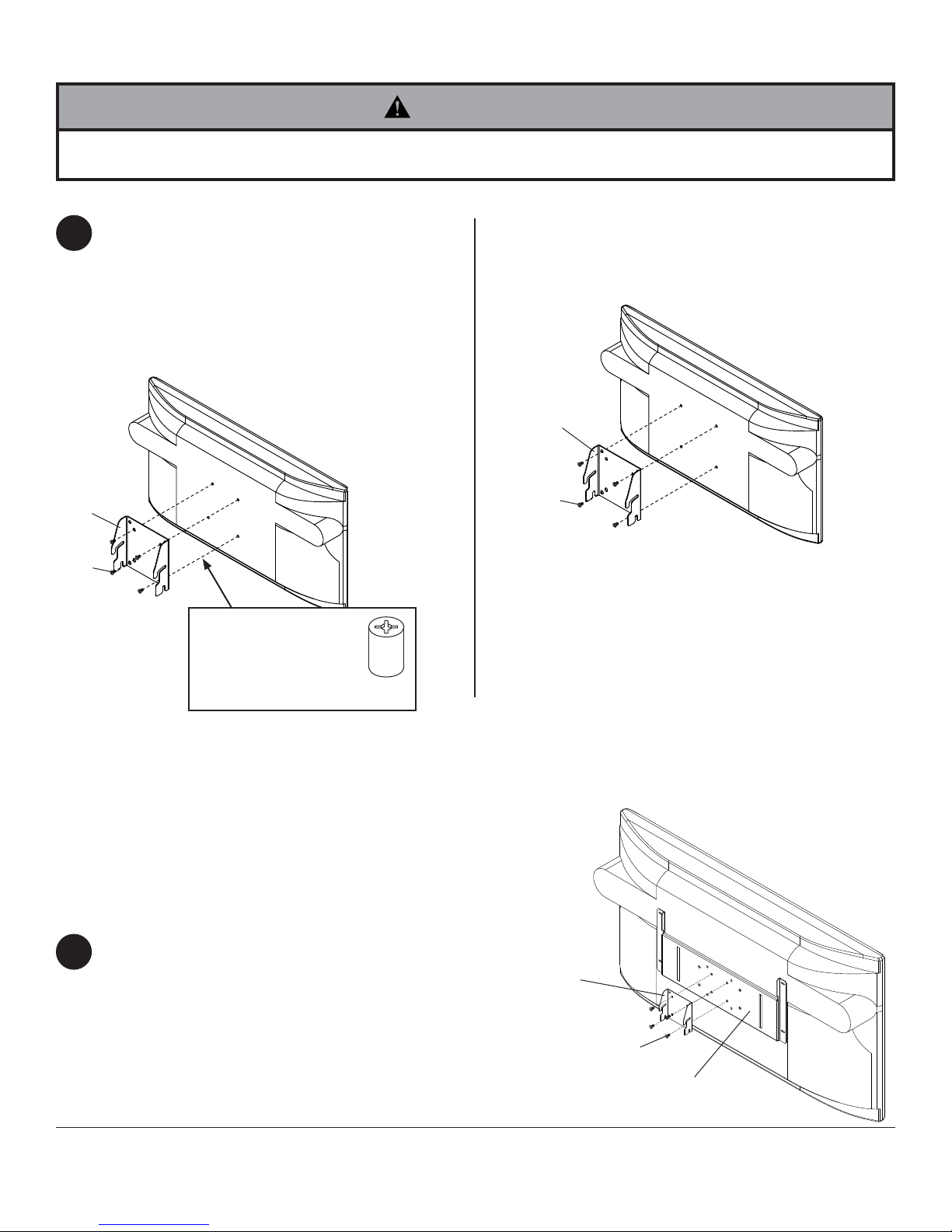
Attaching Hook Bracket to Screen with VESA® 75 or 100 Mounting Pattern
WARNING
• If screws don't get three complete turns in the screen inserts or if screws bottom out and bracket is still not tightly
secured, damage may occur to screen or product may fail.
FOR VESA® 75 MOUNTING PATTERN:
Choose hole pattern as shown below. Attach hook
3
bracket (M) to back of screen using four M4 x 10
mm screws (E) as shown below.
*NOTE: If hole pattern is in a pocket, attach hook
bracket (M) to back of screen using four M4 x 20
mm screws (F) and four retaining spacers (C) as
indicated below.
M
E
*For screens with a
hole pattern in a pocket,
spacers (C) go between
hook plate (M) and
screen.
FOR VESA 100 MOUNTING PATTERN:
Choose hole pattern as shown below. Attach hook
bracket (M) to back of screen using four M4 x 10
mm screws (E) as shown below.
M
E
C
For screen compatibility please refer to the LCD or plasma interface list on our website www.peerlessmounts.com or
call customer care for a screen specifi c PLP adapter bracket models (not UL evaluated).
FOR INSTALLING TO PEERLESS PLP MODEL ADAPTER BRACKET
NOTE: Refer to PLP model adapter bracket instruction
sheet for attachment of adapter bracket to screen.
NOTE: M5 x 10 mm screws are included with the PLP
model adapter bracket
Attach hook bracket (M) to adapter bracket using four
3
M5 x 10 mm screws.
M
M5 X 10 MM SCREW
GENERIC ADAPTER
BRACKET
8 of 46
ISSUED: 01-15-08 SHEET #: 095-9282-2 06-12-09
Page 9
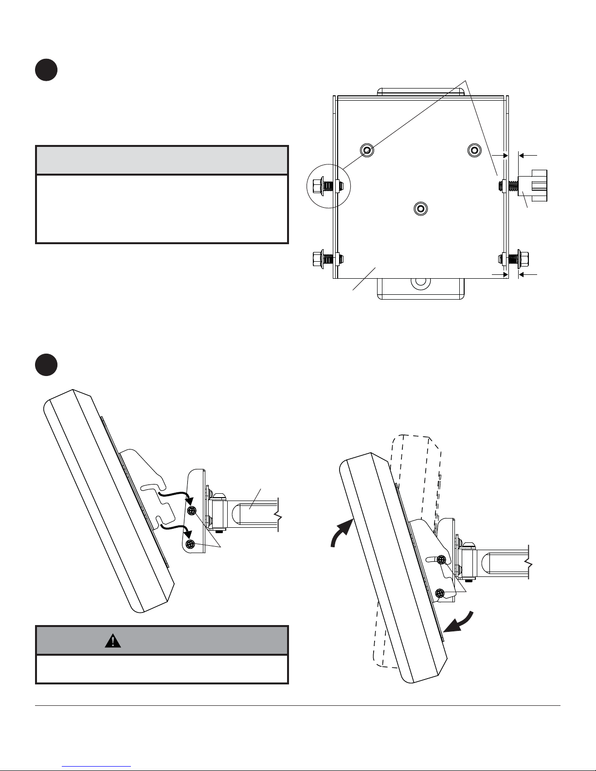
Attaching Tilt Knob to Wall Mount (optional)
For tool-less tilt adjustment, replace one 1/4-20 x
4
1/2" screw with tilt knob (O). Hand thread tilt knob
(O) into wall mount (A) leaving 1/4" exposed thread
as shown in front view.
NOTE: Be sure four 1/4-20 x 1/2" screws have 1/4"
exposed thread.
CAUTION
• Do not tighten screws with excessive force.
Overtightening can cause damage to mount. Tighten
screws to 20 in. • lb (2.26 N.M.) maximum torque.
• Be careful not to pinch fi ngers when opening and
closing mount from the wall.
Installing and Removing Flat Panel Screen
REPLACE LEFT OR RIGHT
1/4-20 x 1/2" SCREW WITH TILT KNOB
1/4"
O
1/4"
A
FRONT VIEW
To attach screen to wall mount (A), hook tilt bracket
5
onto four 1/4-20 x 1/2" screws.
1/4-20 X 1/2"
SCREWS
Adjust screen to desired tilt (15° forward,
5° backward), then tighten four 1/4-20 x 1/2" screws.
Hold screen securely to remove from mount. Loosen four
1/4-20 x 1/2" screws and lift screen away to disengage tilt
bracket from mount.
A
1/4-20 X 1/2"
SCREWS
WARNING
• Always use an assistant or mechanical lifting equipment to safely lift and position the fl at panel screen.
9 of 46
ISSUED: 01-15-08 SHEET #: 095-9282-2 06-12-09
Page 10

CAUTION
• Do not tighten screws with excessive force. Overtightening can cause damage to mount. Tighten screws
to 40 in. • lb (4.5 N.M.) maximum torque.
10-32 x 1/2" screws are pretensioned and require
6
no adjustment. Rotate screen by hand to level
screen. Roll bracket allows 2° roll adjustment.
Cord Management
Attach cable tie anchor (Q) to top or bottom of wall
7
arm (A) using M4 screw (R) as shown.
1/4-20 X 1/2" SCREWS
2° ROLL
ROLL BRACKET
R
Q
A
Secure cords to wall arm (A) using cable tie (P).
7-1
A
10 of 46
P
CORD
ISSUED: 01-15-08 SHEET #: 095-9282-2 06-12-09
Page 11

WARNING
• Do not remove screw or loosen screw until it is no longer engaged with the mount. Doing so may cause the screen
to fall.
Arm Tension Adjustment
If more or less tension is desired in the arm pivot
8
points, do the following:
• To increase tension, turn tension screw(s) clockwise
with 3/16" allen wrench.
• To reduce tension, turn tension screw(s) counterclockwise with 3/16" allen wrench.
NOTE: Do not turn tension screws more than half
a turn.
TENSION
SCREWS
11 of 46
All other brand and product names are trademarks or registered trademarks of their respective owners.
ISSUED: 01-15-08 SHEET #: 095-9282-2 06-12-09
© 2009, Peerless Industries, Inc. All rights reserved.
Peerless Industries, Inc.
3215 W. North Ave.
Melrose Park, IL 60160
www.peerlessmounts.com
Page 12
Instalación y ensamblaje:
Soporte giratorio Paramount™ para pantallas LCD de 22" a 40"
(56 - 102 cm)
Modelos: PP740, PP740-S, PWV240/BK
Características:
• Sostiene pantallas LCD de 22" a 40" (56 - 102 cm)
• Tiene dos puntos de giro de ajuste tensor para ofrecer una gama de
ángulos para ver el televisor
• Es compatible con VESA® 75/100/200 x 100/200 x 200
• Despeja espacios al plegarse plano contra la pared
U
©
L
I
USC
D
2
:
6
0
7
0
8
0
1
0
0
Máxima capacidad de carga: 80 lb (36 kg)
PUBLICADO: 01-15-09 HOJA #: 095-9282-2 06-12-09
Page 13
Español
Nota: Lea la hoja de instrucciones completa antes de comenzar la instalación y el ensamblaje.
ADVERTENCIA
• No comience a instalar su producto de Peerless hasta haber leído y entendido las instrucciones y las advertencias
contenidas en la Hoja de Instalación. Si tiene alguna pregunta acerca de cualquiera de las instrucciones o las advertencias, por favor, llame a Servicio al Cliente de Peerless al 1-800-865-2112 si está en EE. UU. Si es un cliente
internacional, por favor, comuníquese con su distribuidor local.
• Este producto sólo debe ser instalado por una persona que tenga una buena aptitud mecánica, que tenga experiencia en construcción básica de edifi cios y que entienda estas instrucciones en su totalidad.
• Asegúrese de que la superfi cie de apoyo sostendrá, con seguridad, la carga combinada del equipo y todos los fi -
jadores y componentes.
• Nunca sobrepase la capacidad máxima de soportar carga.
• Si va a instalar el producto en una pared con montantes de madera, asegúrese de que los tornillos de montaje estén
anclados en el centro de los montantes. Se recomienda utilizar un localizador de montantes de "borde a borde".
• Siempre cuente con la ayuda de un asistente o utilice un equipo mecánico de izar para levantar y colocar el equipo
con más seguridad.
• Apriete los tornillos con fi rmeza, pero no en exceso. Apretarlos en exceso puede dañar los artículos y puede disminu-
ir signifi cativamente su fuerza de fi jación.
• Este producto está diseñado para uso en interiores solamente. Utilizar este producto en exteriores podría causar fallas del producto y lesiones a individuos.
• Este producto fue diseñado para ser instalado en paredes con la siguiente construcción solamente:
CONSTRUCCIÓN DE LA PARED ACCESORIOS NECESARIOS
x Montante de madera Incluido
x Viga de madera Incluido
x Concreto macizo Incluido
x Bloque de hormigón de escorias Incluido
x Montante de metal No lo instale excepto con el juego de accesorios de Peerless para
montantes de metal (no evaluados por UL)
x Ladrillo Comuníquese con un profesional califi cado (no evaluados por UL)
x ¿Otra superfi cie o no está seguro? Comuníquese con un profesional califi cado
Vea la página 12.
Herramientas necesarias para el ensamblaje
• localizador de montantes (se recomienda uno de "borde a borde")
• destornillador phillips
• taladro
• broca de 5/16" (8 mm) para paredes de concreto y de bloque de hormigón de escorias
• broca de 5/32" (4 mm) para paredes con montantes de madera
• nivel
Tabla de contenido
Lista de piezas......................................................................................................................................................................14
Instalación en una pared con montantes de madera ...........................................................................................................16
Instalación en una pared de concreto macizo o de bloques de hormigón de escorias ........................................................17
®
Fijación de la placa adaptadora a pantallas con confi guraciones de montaje VESA
Instalar en el soporte adaptador modelo PLP de Peerless ..................................................................................................19
Manejo de cables y ajuste tensor del brazo .........................................................................................................................21
13 de 46
.........................................................18
PUBLICADO: 01-15-09 HOJA #: 095-9282-2 06-12-09
Page 14
Antes de comenzar, asegúrese de que su producto contiene todas las piezas que se muestran.
K
A
Las piezas pueden verse un poco distintas a la ilustración.
Español
Lista de piezas
Descripción
soporte para pared 1
anclaje de concreto 2 590-0320
B
espaciador de retención 4 590-5005
C
tornillo phillips M4 x 10 mm 4 504-9012
E
tornillo phillips M4 x 20 mm 4 504-9020
F
tornillo phillips M6 x 12 mm 4 520-1128
G
tornillo de cabeza plana para madera #14
H
x 2-1/2"
tornillo phillips M6 x 20 mm 4 520-9402
I
tornillo phillips M6 x 30 mm 4 510-9109
J
tornillo phillips M5 x 6 mm 4 520-1023
K
arandela plana No. 10 4 540-9400
L
soporte de gancho 1
M
placa adaptadora 1
N
1/4-20 perilla de inclinación
O
sujetacables 3
P
anclaje del sujetacables
Q
tornillo de cabeza plana de 8-32 x 1/4" 3
R
A
Cant.
2 520-1202 520-6165
1 560-1162
3 590-1290
M
PWV240/B
PP740
N° de pieza N° de pieza
095-P1629 095-4629
095-P1561 095-4561
095-P1322 095-4322
560-9711 560-2004
520-1622 520-2622
PP740-S
590-0320
590-5003
520-2027
504-2014
520-2039
520-2040
520-2042
520-2214
540-9442
560-1162
590-1290
BE
CF
G
N
H
IJ
O
P
14 de 46
PUBLICADO: 01-15-09 HOJA #: 095-9282-2 06-12-09
Q
K
L
R
Page 15

Afl oje los tornillos de 1/4-20 x 1/2" para quitar el soporte de gancho (M) de la unidad de soporte de pared antes de
1
la instalación.
A
M
TORNILLOS DE
1/4-20 X 1/2"
Español
15 de 46
PUBLICADO: 01-15-09 HOJA #: 095-9282-2 06-12-09
Page 16

Español
Instalación en una pared con montantes de madera dobles
ADVERTENCIA
• El instalador tiene que asegurarse de que la superfi cie de apoyo sostendrá, con seguridad, la carga combinada del equipo y todos
los fi jadores y componentes.
• Apriete los tornillos de madera de manera que la placa de pared se fi je fi rmemente, pero no en exceso. Apretarlos en exceso
puede dañar los tornillos y puede disminuir signifi cativamente su fuerza de fi jación.
• Nunca apriete a más de 80 pulg-lb (9 N•m).
• Asegúrese de que los tornillos de montaje estén anclados en el centro del montante. Se recomienda utilizar un localizador de montantes de "borde a borde".
• Los accesorios para la instalación que se proveen son para fi jar el soporte a montantes de madera a través de tabique de yeso-
cartón o yeso de espesor estándar. Los instaladores son responsables de suministrar los accesorios necesarios para otros tipos de
instalaciones
Utilizando un localizador de montantes, localice y marque los bordes del montante de madera utilizado para
2
instalar el producto. Se recomienda utilizar un localizador de montantes de "borde a borde". Utilice un nivel para
trazar una línea vertical por el centro del montante. Utilice la placa de pared como plantilla para marcar el centro
de los agujeros sobre la línea vertical. Taladre dos agujeros de 5/32" (4 mm) de diámetro y 2.5" (64 mm) de
profundidad. Fije el soporte de pared (A) a la pared utilizando dos tornillos para madera de cabeza plana de
14 x 2.5" (H), como se muestra.
Pase al paso 3 de la página 18.
(no aprobado por UL).
A
PARED CON
MONTANTE
DE MADERA
PLACA DE PARED
H
16 de 46
PUBLICADO: 01-15-09 HOJA #: 095-9282-2 06-12-09
Page 17

Instalación en una pared de concreto macizo o de bloques de hormigón
Español
de escorias
ADVERTENCIA
• Cuando vaya a instalar soportes de pared de Peerless en bloques de hormigón de escorias, asegúrese de que cuente con una
capa de concreto de un grosor mínimo de 1-3/8" (35 mm) en el agujero, que pueda usar para los anclajes para concreto. ¡No
taladre en juntas de argamasa! Asegúrese de hacer la instalación en la parte sólida del bloque, por lo general, a un mínimo de 1"
(25 mm) del extremo del bloque. Los bloques de hormigón de escorias tienen que cumplir las especifi caciones de la ASTM C-90.
Se sugiere utilizar un taladro eléctrico convencional a baja velocidad para hacer el agujero en vez de un taladro percutor para no
perforar el fondo del agujero al entrar en un vacío o una cavidad.
• El concreto tiene que tener una densidad mínima de 2,000 psi. Es posible que un concreto de menos densidad no sostenga el
anclaje para concreto.
• Asegúrese de que la superfi cie de apoyo sostendrá, con seguridad, la carga combinada del equipo y todos los fi jadores y compo-
nentes.
Nivele y utilice la placa de pared como plantilla
2
para marcar el centro de los agujeros. Taladre
dos agujeros de 5/16" (8 mm) de diámetro a una
profundidad mínima de 2.5" (64 mm). Inserte los
anclajes (B) en los agujeros a ras con la pared.
Coloque el soporte de pared (A) sobre los anclajes y
fíjelo con los tornillos para madera (H). Asegúrese de
que el soporte de pared esté nivelado y ajuste todos
los sujetadores.
ADVERTENCIA
• Apriete los tornillos de manera que la placa de pared se
fi je fi rmemente, pero no en exceso. Apretarlos en exceso
puede dañar los tornillos y puede disminuir signifi cativa-
mente su fuerza de fi jación.
• Nunca apriete a más de 80 pulg-lb (9 N•m).
• Siempre fi je los anclajes para concreto directamente en la
pared que sostiene la carga.
• Nunca fi je los anclajes para concreto a una pared de concreto
recubierta con yeso, tabique de yeso-cartón u otro material de
acabado. Si es inevitable hacer la instalación en una superfi cie
de concreto recubierta con una superfi cie de acabado, la su-
perfi cie de acabado tiene que ser escariada, como se muestra
abajo. Asegúrese de que los anclajes para concreto no se
separen del concreto cuando apriete los tornillos. Si el grosor
de la capa de yeso o tabique de yeso-cartón tiene un grosor
mayor de 5/8" (16 mm), el instalador tiene que suministrar las
fi jaciones especiales
placa
de
pared
(no evaluados por UL).
INCORRECTO
concreto
placa
pared
de
CORRECTO
concreto
1
Taladre los agujeros y inserte los anclajes (B).
2
A
H
Coloque la placa de pared (A) sobre el anclaje (B) y fíjela con el
tornillo (H).
3
Apriete todos los sujetadores.
BLOQUE DE HORMIGÓN
CONCRETO MACIZO
DE ESCORIAS
B
PLACA DE PARED
pared de
concreto
B
B
VISTA EN CORTE
yeso / tabique de yeso-cartón
A
17 de 46
H
PUBLICADO: 01-15-09 HOJA #: 095-9282-2 06-12-09
Page 18

Fijación de la placa adaptadora a pantallas con confi guraciones de montaje
VESA® 200 x 100 ó 200 x 200
NOTA: En el caso de las confi guraciones de montaje VESA® 75 mm y 100
mm, pase a la próxima página.
N
Español
Fije el soporte de gancho (M) a la placa adaptadora
3
(N) usando cuatro tornillos de M5 x 6 mm (K) y cuatro
arandelas N.o 10 (L), como se muestra.
L
M
K
ADVERTENCIA
• Si no se les da tres vueltas completas a los tornillos en los insertos de la pantalla o si los tornillos topan fondo y la placa adaptadora todavía no está fi rme, se podría dañar la pantalla o el producto podría no funcionar bien.
EN EL CASO DE LA CONFIGURACIÓN DE MONTAJE VESA® 200 x 100:
Escoja un patrón de agujeros, como se muestra
3-1
abajo. Fije la placa adaptadora (N) a la parte trasera
de la pantalla usando cuatro tornillos de M4 x 10
mm (E), como se muestra abajo.
*NOTA: Si el tornillo (E) enrosca menos de tres
vueltas, fi je la placa adaptadora (N) a la parte
trasera de la pantalla usando cuatro tornillos de M4
x 20 mm (F) y cuatro espaciadores (C), como se
indica abajo.
Pase al paso 4 de la página 20.
EN EL CASO DE LA CONFIGURACIÓN DE MONTAJE VESA® 200 x 200:
Escoja un patrón de agujeros, como se muestra
abajo. Fije la placa adaptadora (N) a la parte trasera
de la pantalla usando cuatro tornillos de M6 x 12
mm (G), como se muestra abajo.
*NOTA: Si los tornillos (G) enroscan menos de
tres vueltas, fi je la placa adaptadora (N) a la parte
trasera de la pantalla utilizando cuatro tornillos de
M6 x 20 mm (I). Si los tornillos (I) todavía enroscan
menos de tres vueltas, use cuatro tornillos de M6 x
30 mm (J).
Pase al paso 4 de la página 20.
N
E
*En el caso de las pantallas que tienen la confi gu-
ración de agujeros en una
cavidad, los espaciadores
(C) van entre la placa
adaptadora (N) y la pantalla.
C
18 de 46
N
G
PUBLICADO: 01-15-09 HOJA #: 095-9282-2 06-12-09
Page 19

Español
Fijación del soporte de gancho a pantallas con confi guraciones de montaje
VESA® 75 ó 100
ADVERTENCIA
• Si no se les da tres vueltas completas a los tornillos en los insertos de la pantalla o si los tornillos topan fondo y la placa adaptadora todavía no está fi rme, se podría dañar la pantalla o el producto podría no funcionar bien.
EN EL CASO DE LA CONFIGURACIÓN DE
MONTAJE VESA® 75:
3
Escoja un patrón de agujeros, como se muestra
abajo. Fije el soporte de gancho (M) a la parte
trasera de la pantalla usando cuatro tornillos de M4
x 10 mm (E), como se muestra abajo.
*NOTA: Si la confi guración de agujeros está en una
cavidad, fi je el soporte de gancho (M) a la parte
trasera de la pantalla usando cuatro tornillos de M4
x 20 mm (F) y cuatro espaciadores de retención (C),
como se indica abajo.
M
E
*En el caso de las pantallas que tienen la confi gu-
ración de agujeros en una
cavidad, los espaciadores
(C) van entre la soporte de
gancho (M) y la pantalla.
EN EL CASO DE LA CONFIGURACIÓN DE
MONTAJE VESA® 100:
Escoja un patrón de agujeros, como se muestra
abajo. Fije el soporte de gancho (M) a la parte
trasera de la pantalla usando cuatro tornillos de M4
x 10 mm (E), como se muestra abajo.
M
E
C
Para ver una tabla de las pantallas compatibles, consulte la lista de interface de pantallas de LCD o de plasma en
nuestra página web www.peerlessmounts.com o llame a servicio al cliente para preguntar sobre el soporte adaptador
del modelo LC o PLP para una pantalla en específi co (no evaluados por UL).
PARA INSTALAR EN EL SOPORTE ADAPTADOR MODELO PLP DE PEERLESS
NOTA: Consulte la hoja de instrucciones del soporte
adaptador modelo PLP para saber cómo fi jar el sopo-
rte adaptador a la pantalla.
NOTA: Se incluyen los tornillos de M5 x 10 mm con el
soporte adaptador modelo PLP.
Fije el soporte de gancho (M) al soporte adaptador
3
usando cuatro tornillos de M5 x 10 mm.
M
TORNILLO M5 X 10 MM
SOPORTE ADAPT ADOR GENÉRICO
19 de 46
PUBLICADO: 01-15-09 HOJA #: 095-9282-2 06-12-09
Page 20

Fijar la Perilla de Inclinación al Soporte de Pared (opcional)
Español
Para ajustar la inclinación sin herramientas, rem-
4
place un tornillo de 1/4-20 perilla de inclinación (O).
Enrosque la perilla de tensión (O) con la mano en el
soporte de pared (A) y deje 1/4" de la rosca expuesta, como se muestra en la vista delantera.
NOTA: Cerciórese de que los cuatro tornillos de
1/4-20 x 1/2" tengan 1/4" de la rosca expuesta.
REMPLACE EL TORNILLO DE 1/4-20 DE LA IZQUIERDA O
DE LA DERECHA POR LA PERILLA DE INCLINACIÓN
ATENCIÓN
• No apriete los tornillos aplicando demasiada fuerza.
El apriete excesivo podría dañar el soporte. Apriete
los tornillos a 20 pulg-lb (2.26 N•m) de par torsor
máximo.
• Tenga cuidado de no pincharse los dedos cuando
empuje palanca de la pantalla por la parte inferior.
Instalación y desinstalación de la pantalla plana
1/4"
O
1/4"
A
VISTA DELANTERA
Para instalar la pantalla en el soporte de pared (A),
5
enganche el soporte inclinable en cuatro tornillos de
1/4-20 x 1/2".
TORNILLOS DE
1/4-20 X 1/2"
ADVERTENCIA
Ajuste la pantalla a la inclinación deseada (15° hacia
delante, 5° hacia atrás), luego, apriete los cuatro tornillos
de 1/4-20 x 1/2".
Sujete la pantalla fi rmemente para quitarla del soporte.
Afl oje los cuatro tornillos de 1/4-20 x 1/2" y levante
la pantalla retirándola para desenganchar el soporte
inclinable de la unidad de soporte.
A
TORNILLOS DE
1/4-20 X 1/2"
• Siempre cuente con un asistente o con un equipo
mecánico de izar para levantar y colocar los televisores de pantalla plana con más seguridad.
20 de 46
PUBLICADO: 01-15-09 HOJA #: 095-9282-2 06-12-09
Page 21

Español
ATENCIÓN
• No apriete los tornillos con fuerza excesiva. Apretarlos en exceso puede dañar el soporte. Apriete los tornillos a un
máximo de 40 pulg-lb (4.5 N•m) de par torsor.
Los tornillos de tensión de 10-32 x 1/2" están
6
prefi jados y no necesitan ajuste. Gire la pantalla con
la mano para nivelarla. El soporte rotatorio permite
un ajuste de 2° de la rotación.
Manejo de Cables
Fije el anclaje del sujetacables (Q) a la parte
7
superior o inferior del brazo de pared (A) utilizando
un tornillo de M4 (R), como se muestra.
TORNILLOS DE 1/4-20 X 1/2"
ROTACIÓN DE 2°
SOPORTE ROTATORIO
R
Q
A
Fije los cables al brazo de pared (A) utilizando el
7-1
sujetacables (P).
A
21 de 46
P
CABLE
PUBLICADO: 01-15-09 HOJA #: 095-9282-2 06-12-09
Page 22

ADVERTENCIA
• No quite ni afl oje el tornillo hasta que ya no esté enganchado al soporte. Hacerlo podría causar que se caiga la
pantalla.
Ajuste Tensor del Brazo
Si desea más o menos tensión en los puntos gira-
8
dores del brazo, haga lo siguiente:
• Para aumentar la tensión, gire el tornillo o los tornillos de tensión en el sentido del movimiento de las
manecillas del reloj con una llave allen de 3/16".
• Para disminuir la tensión, gire el tornillo o los tornillos de tensión en el sentido contrario al movimiento
de las manecillas del reloj con una llave allen de
3/16".
NOTA: No les dé más de media vuelta a los tornil-
los de tensión.
TORNILLOS
DE TENSIÓN
Español
22 de 46
Cualesquiera otras marcas y nombres de productos son marcas comerciales o registradas de sus respectivos dueños.
PUBLICADO: 01-15-09 HOJA #: 095-9282-2 06-12-09
© 2009, Peerless Industries, Inc. Todos los derechos reservados.
Peerless Industries, Inc.
3215 W. North Ave.
Melrose Park, IL 60160
www.peerlessmounts.com
Page 23

Installation et montage :
Support pivotant Paramount™ pour écrans ACL de 22 à 40 po
(56 - 102 cm)
Modèles: PP740, PP740-S, PWV240/BK
Caractéristiques :
• Convient aux écrans ACL de 56 à 102 cm (22 à 40 po)
• Deux points de pivotement pouvant être tensionnés pour un
réglage étendu de l’angle de visionnement
• Compatible avec la norme VESA® 75/100/200 x 100/200 x 200
• Libère de l’espace en se repliant à plat contre le mur
U
©
L
I
USC
D
2
:
6
0
7
0
8
0
1
0
0
Capacité de charge maximale: 36 kg (80 lb)
PUBLIÉ LE : 01-15-08 FEUILLE no : 095-9282-2 06-12-09
Page 24

Français
Remarque : lisez entièrement la fi che d’instructions avant de commencer l’installation et l’assemblage.
AVERTISSEMENT
• Ne commencez pas à installer votre produit Peerless avant d’avoir lu et assimilé les instructions et les avertissements contenus dans cette fi che d’installation. Pour toute question concernant les instructions ou les avertissements,
veuillez appeler le service à la clientèle de Peerless au 1-800-865-2112; tous les clients internationaux sont priés de
contacter leur distributeur local.
• Ce produit doit être installé uniquement par quelqu’un possédant une bonne aptitude à la mécanique, une expérience
de la construction immobilière et ayant bien compris ces instructions.
• Assurez-vous que la surface de support puisse soutenir sans danger la charge totale de l’équipement ainsi que des
pièces et composants qui y sont attachés.
• Ne dépassez jamais la capacité de charge maximum établie par l’UL. Reportez-vous à la page 23.
• Lors d’une installation sur un mur à montants en bois, assurez-vous que les vis de montage sont ancrées au centre
des montants. L’utilisation d’un localisateur de montants « bord à bord » est fortement recommandée.
• Pour lever et positionner l’équipement en toute sécurité, faites-vous toujours aider par une autre personne ou utilisez
un dispositif de levage mécanique.
• Serrez fermement les vis, mais sans excès. Un serrage excessif peut endommager les composants et en réduire
considérablement la capacité de support.
• Ce produit est conçu uniquement pour un usage intérieur. L’utilisation de ce produit à l’extérieur peut causer une défaillance du produit et des blessures corporelles.
• Ce produit a été conçu uniquement pour une installation sur les types de murs ci-dessous :
TYPE DE MUR PIÈCES DE FIXATION REQUISES
x Montant en bois Incluses
x Poutre en bois Incluses
x Béton plein Incluses
x Bloc de béton de mâchefer Incluses
x Montant métallique Ne pas installer sur ce type de mur sauf à l’aide de l’ensemble d’accessoires
Peerless pour montants métalliques (non évalué UL)
x Brique Contacter un professionnel qualifi é (non évalué UL)
x Autre, ou vous n’êtes pas sûr ? Contacter un professionnel qualifi é
Outils nécessaires au montage
• localisateur de montants (un localisateur de montants « bord à bord » est recommandé)
• tournevis phillips
• perceuse
• foret de 5/32 po (4 mm) pour les murs à montants en bois
• foret de 5/16 po (8 mm) pour les murs à block de béton
• niveau
Table des matières
Liste des pièces ....................................................................................................................................................................25
Installation sur des murs à montants en bois .......................................................................................................................27
Installation sur du béton plein et du bloc de béton ...............................................................................................................28
Fixation de la plaque d’adaptation à un écran compatible à la norme de montage VESA® .................................................29
Installation à un support adaptateur Peerless de modèle PLP .............................................................................................30
Organisation des câbles et réglage de la tension du bras ...................................................................................................32
24 sur 46
PUBLIÉ LE : 01-15-08 FEUILLE no : 095-9282-2 06-12-09
Page 25

Avant de commencer, assurez-vous que toutes les pièces indiquées sont incluses avec le produit.
K
A
Français
Liste des pièces
Description
monture murale
anclaje de concreto 2 590-0320
B
entretoise de retenue 4 590-5005
C
Vis cruciforme M4 x 10 mm 4 504-9012
E
Vis cruciforme M4 x 20 mm 4 504-9020
F
Vis cruciforme M6 x 12 mm 4 520-1128
G
Vis à bois à tête plate N° 14 x 2 1/2 po 2 520-1202 520-6165
H
Vis cruciforme M6 x 20 mm 4 520-9402
I
Vis cruciforme M6 x 30 mm 4 510-9109
J
Vis cruciforme M5 x 6 mm 4 520-1023
K
Rondelle plate N° 10 4 540-9400
L
Support à crochets 1
M
Plaque d'adaptation
N
1/4-20 bouton d'inclinaison
O
l'attache de câble
P
Fixez l’ancrage
Q
Vis cruciforme à tête plate 8-32 x 1/4"
R
Il est possible que les pièces semblent légèrement différentes de celles illustrées ici.
A
M
PWV240/B
PP740
N° de Pièce N° de Pièce
Qté.
095-P1629 095-4629
1
095-P1561 095-4561
095-P1322 095-4322
1
1 560-1162
560-9711 560-2004
3
3 590-1290
520-1622 520-2622
3
BE
PP740-S
590-0320
590-5003
520-2027
504-2014
520-2039
520-2040
520-2042
520-2214
540-9442
560-1162
590-1290
CF
G
N
H
IJ
O
P
25 sur 46
PUBLIÉ LE : 01-15-08 FEUILLE no : 095-9282-2 06-12-09
Q
K
L
R
Page 26

Desserrez les vis de 1/4-20 x 1/2 po pour retirer le crochet de support (M) de la monture murale avant l’installation.
1
A
M
VIS DE
1/4-20 X 1/2 PO
Français
26 sur 46
PUBLIÉ LE : 01-15-08 FEUILLE no : 095-9282-2 06-12-09
Page 27

Français
Installation sur un mur à montant en bois simple
AVERTISSEMENT
• L’installateur doit s’assurer que la surface de support pourra soutenir sans danger la charge combinée de
l’équipement, de toute sa visserie et de tous ses composants.
• Serrez les vis à bois de manière que la plaque murale soit fermement fi xée, mais sans excès. Un serrage excessif
peut endommager les vis et en réduire considérablement le pouvoir de maintien.
• Ne serrez jamais à plus de 9 Nm (80 po-lb).
• Assurez-vous que les vis de montage sont ancrées au centre des montants. L’usage d’un localisateur de montants
« bord à bord » est fortement conseillé.
• La visserie est fournie pour fi xer la monture à travers une cloison sèche ou du plâtre d’épaisseur standard et dans des
montants en bois. Il appartient aux installateurs de fournir la visserie nécessaire pour d’autres types de situations (non
approuvées UL).
À l’aide d’un localisateur de montants, repérez et marquez les bords du montant en bois utilisé pour installer ce
2
support. L’utilisation d’un localisateur de montants « bord à bord » est fortement recommandée. À l’aide d’un
niveau, tracez une ligne verticale le long du centre du montant. Utilisez la plaque murale comme gabarit pour
marquer le centre des trous le long de la ligne verticale. Percez deux trous de 5/32 po (4 mm) de dia. et de 2,5 po
(64 mm) de profondeur. Fixez le support mural (A) au mur à l’aide de deux vis à bois à tête plate no 14 x 2,5 po (H)
comme illustré.
Passez à l’étape 3 à la page 29.
A
MUR À MONTANT
EN BOIS
PLAQUE MURALE
H
27 sur 46
PUBLIÉ LE : 01-15-08 FEUILLE no : 095-9282-2 06-12-09
Page 28

Français
Installation sur du béton plein ou un bloc de béton de mâchefer
AVERTISSEMENT
• Si vous installez des montures murales Peerless sur un bloc de béton de mâchefer, vérifi ez que vous disposez d’une
épaisseur de béton d’au moins 34 mm (1 3/8 po) dans le trou destiné aux ancrages de béton. Ne percez pas dans les
joints de mortier ! Veillez à effectuer le montage dans une partie pleine du bloc, généralement à au moins 25 mm
(1 po) du côté du bloc. Le bloc de béton de mâchefer doit être conforme aux spécifi cations de l’ASTM C-90. Pour
percer le trou, il est conseillé d’utiliser une perceuse électrique standard sur un réglage bas au lieu d’un marteau perforateur, afi n d’éviter de briser la partie arrière du trou lorsque vous pénétrez un vide ou une cavité.
• Le béton doit avoir une densité minimale de 2 000 psi. Un béton de densité moindre risquerait de ne pas retenir un
ancrage de béton.
• Assurez-vous que la surface de support pourra soutenir sans danger la charge combinée de l’équipement, de toute sa
visserie et de tous ses composants.
Mettez à niveau la plaque murale et utilisez-la
2
comme gabarit pour marquer le centre des trous.
Percez deux trous de 5/16 po (8 mm) de dia. à une
profondeur minimale de 2,5 po (64 mm). Insérez les
chevilles d’ancrage (B) dans les trous au ras du mur.
Placez le support mural (A) sur l’ancrage et fi xez-la à
l’aide de vis à bois (H). Assurez-vous que le support
mural est à niveau et serrez toues les fi xations.
AVERTISSEMENT
• Serrez les vis de manière que la plaque murale soit
fermement fi xée, mais sans excès. Un serrage exces-
sif peut endommager les vis et en réduire considérablement le pouvoir de maintien.
• Ne serrez jamais à plus de 9 Nm (80 po-lb).
• Fixez toujours des ancrages de béton directement sur
du béton porteur.
• Ne fi xez jamais d’ancrages sur du béton recouvert
de plâtre, une cloison sèche ou autre matériau de
fi nition. Si vous ne pouvez pas éviter d’effectuer le
montage sur du béton recouvert d’une surface de
fi nition, celle-ci doit être chambrée, comme indiqué cidessous. Assurez-vous que les ancrages de béton ne
se séparent pas du béton lorsque vous serrez les vis.
Si l’épaisseur du plâtre / de la cloison sèche dépasse
16 mm (5/8 po), des fi xations adaptées devront être
fournies par l’installateur (non évalué UL).
1
concrete
surface
B
Percez les trous et insérez les chevilles d’ancrage (B).
2
A
H
Posez la plaque murale (A) sur l’ancrage (B) et fi xez-la à l’aide
d’une vis (H).
3
Serrez toutes les fi xations.
BLOC DE BÉTON DE
BÉTON PLEIN
MÂCHEFER
B
INCORRECT CORRECT
béton
plaque
mural
plâtre /
VUE EN COUPE
cloison sèche
plaque
mural
plâtre /
cloison sèche
béton
28 sur 46
PLAQUE
MURALE
A
B
H
PUBLIÉ LE : 01-15-08 FEUILLE no : 095-9282-2 06-12-09
Page 29

Français
Fixation de la plaque d’adaptation à un écran compatible à la norme de montage
VESA® 200 x 100 ou 200 x 200
N
REMARQUE : Pour les confi gurations vesa 75 mm et 100 mm, voir la page
suivante.
Fixez le support d’accrochage (M) à la plaque d’adaptation
3
(N) à l’aide de quatre vis M5 x 6 mm (K) et de rondelles no
10 (L) comme illustré.
L
M
K
AVERTISSEMENT
• Si les vis ne sont pas enfoncées de trois tours complets dans les inserts ou si elles sont serrées au maximum sans
parvenir à fi xer solidement la plaque d’adaptation, l’écran peut être abîmé ou le produit détérioré.
POUR LA CONFIGURATION DE MONTAGE
VESA® 200 x 100 :
Choisissez la confi guration de trous illustrée ci-
3-1
dessous. Fixez la plaque d’adaptation (N) au dos
de l’écran à l’aide de quatre vis M4 x 10 mm (E)
comme illustré ci-dessous.
* REMARQUE : Si la vis (E) ne se visse pas sur au
moins trois fi letages, fi xez la plaque d’adaptation
(N) au dos de l’écran à l’aide de quatre vis M4 x 20
mm (F) et quatre entretoises (C) comme indiqué
ci-dessous.
Passez à l’étape 4 à la page 31.
POUR LA CONFIGURATION DE MONTAGE
VESA® 200 x 200 :
Choisissez la confi guration de trous illustrée ci-
dessous. Fixez la plaque d’adaptation (N) au dos
de l’écran à l’aide de quatre vis M6 x 12 mm (G)
comme illustré ci-dessous.
*REMARQUE : Si la vis (G) ne se visse pas sur au
moins trois fi letages, fi xez la plaque d’adaptation (N)
au dos de l’écran à l’aide de quatre vis M6 x 20 mm
(I). Si la vis (I) ne se visse toujours pas sur au moins
trois fi letages, utilisez quatre vis M6 x 30 mm (J).
Passez à l’étape 4 à la page 31.
*Pour les écrans dont la con-
N
E
fi guration de trous est dans un
creux, les entretoises (C) doivent
être placées entre la plaque
d’adaptation (N) et l’écran.
C
29 sur 46
N
G
PUBLIÉ LE : 01-15-08 FEUILLE no : 095-9282-2 06-12-09
Page 30

Français
Fixation du support d’accrochage à un écran compatible à la norme de montage
VESA® 75 ou 100
AVERTISSEMENT
• Si les vis ne sont pas enfoncées de trois tours complets dans les inserts ou si elles sont serrées au maximum sans
parvenir à fi xer solidement la plaque d’adaptation, l’écran peut être abîmé ou le produit détérioré.
POUR LA CONFIGURATION DE MONTAGE
VESA® 75 :
3
Choisissez la confi guration de trous illustrée ci-
dessous. Fixez le support d’accrochage (M) au dos
de l’écran à l’aide de quatre vis M4 x 10 mm (E)
comme illustré ci-dessous.
* REMARQUE : Si la confi guration de trous est
dans un creux, fi xez le support d’accrochage (M) au
dos de l’écran à l’aide de quatre vis M4 x 20 mm (F)
et quatre entretoises de retenue (C) comme indiqué
ci-dessous.
M
E
*Pour les écrans dont la confi guration de trous est dans un
creux, les entretoises (C) doivent
être placées entre la support
d’accrochage (M) et l’écran.
POUR LA CONFIGURATION DE MONTAGE
VESA® 100 :
Choisissez la confi guration de trous illustrée ci-
dessous. Fixez le support d’accrochage (M) au dos
de l’écran à l’aide de quatre vis M4 x 10 mm (E)
comme illustré ci-dessous.
M
E
C
Pour déterminer la compatibilité avec l’écran, veuillez consulter la liste d’interfaces avec les écrans ACL ou plasma sur
notre site Web à l’adresse www.peerlessmounts.com ou appeler le service à la clientèle pour demander quel type de
support adaptateur modèle PLP s’adapte à votre écran (non évalués aux normes UL).
INSTALLATION À UN SUPPORT ADAPTATEUR PEERLESS DE MODÈLE PLP
REMARQUE : Veuillez vous reporter à la feuille d’instructions
sur le support adaptateur de modèle PLP pour la fi xation du
support adaptateur à l’écran.
REMARQUE : Des vis M5 x 10 mm sont fournies avec le support adaptateur de modèle PLP.
Fixez le support d’accrochage (M) au support adaptateur à
3
l’aide de quatre vis M5 x 10 mm.
M
VIS M5 X 10 MM
SUPPORT ADAPT ATEUR GÉNÉRIQUE
30 sur 46
PUBLIÉ LE : 01-15-08 FEUILLE no : 095-9282-2 06-12-09
Page 31

Fixation du Bouton D'Inclinaison au Support Mural (facultatif)
Français
Pour régler l'inclinaison sans outil, remplacez une
4
vis de 1/4-20 bouton d'inclinaison (O). Vissez manuellement le bouton d'inclinaison (O) sur le support
mural (A) en laissant 1/4 po de fi letage exposé
comme illustré dans la vue de face.
REMARQUE : Assurez-vous que quatre vis 1/4-20 x
1/2 po aient 1/4 po de fi letage exposé.
AVERTISSEMENT
• N’exercez pas une force excessive sur les vis. Un
serrage excessif peut endommager le support.
Serrez les vis à un couple maximal de 20 po-lb (2,26
Nm).
• Veillez à ne pas vous pincer les doigts lorsque vous
poussez l’écran par le bas.
Montage et démontage d’un écran plat
REMPLACEZ LA VIS DE 1/4-20 GAUCHE OU
DROITE PAR LE BOUTON D'INCLINAISON
1/4"
O
1/4"
A
VUE DE FACE
Pour fi xer l'écran au support mural (A), accrochez le
5
support inclinable sur quatre vis de 1/4-20 x 1/2 po.
VIS DE 1/4-20
X 1/2 PO
Réglez l'écran dans la position d’inclinaison souhaitée (15°
vers l'avant, 5° vers l'arrière), puis resserrez quatre vis de
1/4-20 x 1/2 po.
Tenez fermement l'écran pour le retirer du support.
Desserrez quatre vis de 1/4-20 x 1/2 po et soulevez l'écran
pour dégager le support inclinable du support.
A
VIS DE 1/4-20
X 1/2 PO
AVERTISSEMENT
• Pour lever et positionner l’écran plat en toute sécurité, faites-vous toujours aider par une autre personne
ou utilisez un dispositif de levage mécanique.
31 sur 46
PUBLIÉ LE : 01-15-08 FEUILLE no : 095-9282-2 06-12-09
Page 32

Français
AVERTISSEMENT
• N’exercez pas une force excessive sur les vis. Un serrage excessif peut endommager le support. Serrez les vis à
un couple maximal de 40 po-lb (4,5 Nm).
Les vis de 10-32 x 1/2 po sont précontraintes et ne
6
nécessitent aucun réglage. Faites pivoter l'écran
à la main pour le mettre de niveau. Le support de
pivotement latéral permet un réglage du pivotement
latéral sur 2°.
PIVOTEMENT LATÉRAL SUR 2°
Organisation des Câbles
Fixez l’ancrage (Q) de l’attache de câble sur le haut
7
ou le bas du bras mural (A) à l’aide de vis M4 (R)
comme illustré.
VIS DE 1/4-20 X 1/2 PO
SUPPORT DE PIVOTEMENT LATÉRAL
R
Q
A
Attachez les câbles au support mural (A) à l'aide de
7-1
l'attache de câble (P).
A
32 sur 46
P
CÁBLE
PUBLIÉ LE : 01-15-08 FEUILLE no : 095-9282-2 06-12-09
Page 33

AVERTISSEMENT
• Ne pas retirer ni desserrer la vis avant qu’elle ne soit complètement dégagée du support. Cela risquerait de faire
tomber l’écran.
Réglage de la tension du bras
Pour augmenter ou diminuer la tension des points de
8
pivotement du bras, procédez comme suit :
• Pour augmenter la tension, tournez la ou les vis de
tension dans le sens des aiguilles d’une montre à
l’aide d'une clé hexagonale de 3/16 po.
• Pour diminuer la tension, tournez la ou les vis de
tension dans le sens contraire des aiguilles d’une
montre à l’aide d'une clé hexagonale de 3/16 po.
REMARQUE : Ne tournez pas les vis de tension de
plus d’un demi-tour.
VIS DE
TENSION
Français
33 sur 46
Tous les autres noms de marques et de produits sont des marques de commerce ou déposées de leurs propriétaires respectifs.
PUBLIÉ LE : 01-15-08 FEUILLE no : 095-9282-2 06-12-09
© 2009, Peerless Industries, Inc. Tous droits réservés.
Peerless Industries, Inc.
3215 W. North Ave.
Melrose Park, IL 60160
www.peerlessmounts.com
Page 34

Anbringung und Zusammenbau:
Paramount™-Schwenkhalterung für LCD-Bildschirme
von 22-40 Zoll (56 - 102 cm)
Modelle: PP740, PP740-S, PWV240/BK
Merkmale:
• Für LCD-Bildschirme von 56 - 102 cm (22 bis 40 Zoll)
• Zwei spannbare Gelenke bieten vielseitige Einstellmöglichkeiten des
Betrachtungswinkels
• Kompatibel mit VESA® 75/100/200 x 100/200 x 200
• Flach an die Wand klappbare Ausführung spart Platz
U
©
L
I
USC
D
2
:
6
0
7
0
8
0
1
0
0
Maximale Tragfähigkeit: 36 kg (80 lb)
AUSGEGEBEN: 01-15-08 BLATT NR.: 095-9282-2 06-12-09
Page 35

Deutsch
HINWEIS: Lesen Sie die gesamte Anleitung, bevor Sie mit der Anbringung und dem Zusammenbau beginnen.
ACHTUNG
• Beginnen Sie mit der Anbringung Ihres Peerless-Produkts erst, nachdem Sie die in dieser Montageanleitung
enthaltenen Anleitungen und Achtungshinweise gelesen und sich gründlich mit ihnen vertraut gemacht haben. Falls
Sie Fragen hinsichtlich irgendeiner der Anleitungen oder Achtungshinweise haben, wenden Sie sich in den USA bitte
an den Peerless-Kundendienst unter der Rufnummer 1-800-865-2112. Kunden im Ausland wenden sich bitte an den
örtlichen Vertragshändler.
• Dieses Produkt darf nur von Personen mit guten mechanischen Fähigkeiten montiert werden, die über Erfahrung in
den Grundlagen der Baukonstruktion verfügen und diese Anleitungen vollkommen verstehen.
• Vergewissern Sie sich, dass die tragende Fläche das Gesamtgewicht der Geräte und allen daran angebrachten
Befestigungsteilen und Komponenten sicher tragen kann.
• Die maximale Tragfähigkeit darf niemals überschritten werden. Siehe Seite 34.
• Achten Sie bei der Anbringung an Holzständern darauf, dass die Befestigungsschrauben jeweils in der Mitte der
Holzständer verankert sind. Am besten eignet sich ein Balkenfi nder mit genauer Kantenanzeige.
• Ziehen Sie immer eine zusätzliche Person heran oder verwenden Sie mechanische Hebegeräte, um Geräte sicher
zu heben und zu positionieren.
• Ziehen Sie die Schrauben fest an, ohne sie zu überdrehen. Durch Überdrehen können die Teile beschädigt werden,
wodurch ihr Haltevermögen stark reduziert wird.
• Dieses Produkt ist nur für den Gebrauch innerhalb von Gebäuden bestimmt. Eine Verwendung dieses Produkts im
Freien kann zu Produktausfall und Personenschaden führen.
• Dieses Produkt wurde nur für die Anbringung an den folgenden Wandkonstruktionen ausgelegt:
Wandkonstruktion Erforderliche Befestigungsteile
x Holzständer Inbegriffen
x Holzbalken Inbegriffen
x Massivbeton Inbegriffen
x Porenbetonstein Inbegriffen
x Metallständer Nur Mit Metallständer-zubehörsatz Von Peerless Anbringen
(nicht UL-zugelassene)
x Ziegel Qualifi zierten Fachmann Konsultieren (nicht UL-zugelassene)
x Andere oder nicht sicher? Qualifi zierten Fachmann Konsultieren
Für den Zusammenbau erforderliche Werkzeuge
• Balkenfi nder (Balkenfi nder mit genauer Kantenanzeige empfohlen)
• Kreuzschlitzschraubendreher
• Bohrer
• 5/16 Zoll (8 mm) Bit für Beton- und Porenbetonsteinwand
• 5/32 Zoll (4 mm) Bit für Holzständerwand
• Wasserwaage
Inhaltsverzeichnis
Teileliste ................................................................................................................................................................................36
Anbringung an Wand Holzständerreihen ..............................................................................................................................38
Anbringung an Massivbeton oder Porenbetonstein .............................................................................................................39
Befestigung der Adapterplatte am Bildschirm unter Verwendung von VESA-Montagemuster .............................................40
Befestigung an Peerless-Adapterhalterung Modell PLP ......................................................................................................41
Kabelführung und Einstellung der Armspannung ................................................................................................................43
35 von 46
AUSGEGEBEN: 01-15-08 BLATT NR.: 095-9282-2 06-12-09
Page 36

Bevor Sie beginnen, stellen Sie sicher, dass alle Teile gezeigt werden, die mit Ihrem Produkt.
K
A
Deutsch
Teileliste
Beschreibung
Wandhaltereinheit 1
Betondübel 2 590-0320
B
Abstandhalter 4 590-5005
C
M4 x 10 mm Kreuzschlitzschraube 4 504-9012
E
M4 x 20 mm Kreuzschlitzschraube 4 504-9020
F
M6 x 12 mm Kreuzschlitzschraube 4 520-1128
G
Nr. 14 x 2,5 Zoll Sechskant-Holzschraube 2 520-1202 520-6165
H
M6 x 20 mm Kreuzschlitzschraube 4 520-9402
I
M6 x 30 mm Kreuzschlitzschraube 4 510-9109
J
M5 x 6 mm Kreuzschlitzschraube 4 520-1023
K
Unterlegscheibe Nr. 10 4 540-9400
L
Hakenhalterung 1
M
Adapterplatte 1
N
1/4-20 Schrauben durch den Neigungsknopf
O
Kabelbinder
P
Kabelbinderanker
Q
Flat-Kopf-Schraube 8-32 x 1/4"
R
DieTeile können leicht anders als dargestellt.
A
M
PWV240/B
PP740
Teile Nr. Teile Nr.
Anz.
095-P1629 095-4629
095-P1561 095-4561
095-P1322 095-4322
1 560-1162
560-9711 560-2004
3
3 590-1290
520-1622 520-2622
3
BE
PP740-S
590-0320
590-5003
520-2027
504-2014
520-2039
520-2040
520-2042
520-2214
540-9442
560-1162
590-1290
CF
G
N
H
IJ
O
P
36 von 46
AUSGEGEBEN: 01-15-08 BLATT NR.: 095-9282-2 06-12-09
Q
K
L
R
Page 37

Lösen Sie die 1/4-20 x 1/2 Zoll Schrauben, um die Hakenhalterung (M) vor der Anbringung vom Wandhalter zu
1
entfernen.
A
M
1/4-20 X 1/2 ZOLL
SCHRAUBEN
Deutsch
37 von 46
AUSGEGEBEN: 01-15-08 BLATT NR.: 095-9282-2 06-12-09
Page 38

Deutsch
Anbringung an Wand Holzständerreihen
ACHTUNG
• Bei der Anbringung muss darauf geachtet werden, dass die Wand die kombinierte Last von Bildschirm und allen Befestigungsteilen und
-komponenten tragen kann.
• Ziehen Sie die Schrauben fest genug an, dass die Wandplatte sicher befestigt ist, doch ohne sie zu überdrehen. Durch Überdrehen können die
Schrauben beschädigt werden, wodurch ihr Haltevermögen stark reduziert wird.
• Das Drehmoment darf 80 in. • lb (9 Nm.) auf keinen Fall überschreiten.
• Achten Sie darauf, dass die Befestigungsschrauben jeweils in der Mitte der Holzständer verankert werden. Am besten eignet sich ein Balkenfi nder
mit genauer Kantenanzeige.
• Die mitgelieferten Befestigungsteile sind für die Befestigung des Halters durch Trocken- oder Putzwand standardmäßiger Stärke in Holzständer
vorgesehen. Für die Anbringung an anders konstruierten Wänden müssen andere (nicht UL-zugelassene) Befestigungsteile verwendet werden.
Bestimmen Sie die Kanten des Ständers mithilfe eines Balkenfi nders. Am besten eignet sich ein Balkenfi nder mit
2
genauer Kantenanzeige. Verwenden Sie die Kanten als Richtlinie und ziehen Sie eine senkrechte Linie entlang der
Mitte des Ständers. Legen Sie die Wandplatte (A) als Schablone an die Wand und achten Sie darauf, dass sich die
beiden Montagebohrungen auf der Mittellinie des Holzständers befi nden. Richten Sie die Platte waagerecht aus
und markieren Sie den Mittelpunkt der Löcher. Bohren Sie zwei Löcher mit einem Durchmesser von 4 mm (5/32
Zoll) und einer Tiefe von 64 mm (2,5 Zoll). Achten Sie darauf, dass die Wandplatte waagerecht ist und befestigen
Sie sie wie abgebildet mit zwei Nr. 14 x 2,5 Zoll Holzschrauben (H).
FAHREN SIE MIT SCHRITT 3 AUF SEITE 40 FORT.
A
HOLZSTÄNDERWAND
WANDPLATTE
H
38 von 46
AUSGEGEBEN: 01-15-08 BLATT NR.: 095-9282-2 06-12-09
Page 39

Deutsch
Anbringung an Massivbeton oder Porenbetonstein
ACHTUNG
• Bei der Anbringung von Peerless-Wandhaltern an Porenbetonstein muss sichergestellt werden, dass die tatsächliche Stärke des Betons, in
den das Loch für die Betondübel gebohrt wird, mindestens 35 mm (1 3/8 Zoll) beträgt. Bohren Sie nicht in Mörtelfugen! Achten Sie darauf,
dass die Anbringung an einem massiven Teil des Blocks erfolgt, im Allgemeinen mindestens 25 mm (1 Zoll) von der Blockseite entfernt. Die
Porenbetonsteine müssen den Spezifi kationen der ASTM-Norm C-90 entsprechen. Wir empfehlen, zum Bohren des Lochs anstelle eines
Schlagbohrers einen standardmäßigen Elektrobohrer bei niedriger Einstellung zu verwenden, um zu verhindern, dass die Bohrungsrückseite beim
Eintritt in einen Leer- oder Hohlraum ausbricht.
• Die Betondruckfestigkeit muss mindestens 2000 psi betragen. In Beton mit geringerer Druckfestigkeit kann der Betondübel u. U. nicht halten.
• Vergewissern Sie sich, dass die Wand das Vierfache des Gesamtgewichts von Geräten und allen daran angebrachten Befestigungsteilen und
Komponenten sicher tragen kann.
Achten Sie darauf, dass die Wandplatte (A)
2
waagerecht ist und verwenden Sie sie als Schablone
zum Markieren der beiden Montagebohrungen. Bohren
1
BEFESTIGUNGSFLÄCHE
Sie zwei Löcher mit einem Durchmesser von 8 mm
(5/16 Zoll) und einer Mindesttiefe von 64 mm (2,5 Zoll).
Stecken Sie Dübel (B) in die Löcher, bis diese bündig
mit der Wand abschließen (siehe Abbildung rechts).
Bohren Sie Löcher und setzen Sie die Dübel (D) ein.
B
Halten Sie die Wandplatte auf den Dübeln fest und
befestigen Sie sie mit zwei Schrauben (H). Richten Sie
2
A
sie waagerecht aus und ziehen Sie dann sämtliche
Befestigungsteile an.
H
ACHTUNG
• Ziehen Sie die Schrauben fest genug an, dass die Wandplatte
sicher befestigt ist, doch ohne sie zu überdrehen. Durch
Überdrehen können die Schrauben beschädigt werden, wodurch ihr
Haltevermögen stark reduziert wird.
• Das Drehmoment darf 80 in. • lb (9 Nm.) auf keinen Fall
überschreiten.
• Betonspreizdübel müssen stets direkt am tragenden Beton
angebracht werden.
• Betonspreizdübel dürfen auf keinen Fall an Beton befestigt
werden, der mit Verputz, Trockenwandmaterial oder anderem
Deckschichtmaterial bedeckt ist. Falls es nicht vermeiden lässt,
die Montage an einer Betonfl äche mit Deckschicht vorzunehmen,
muss wie nachstehend dargestellt eine Senkung in die Deckschicht
gebohrt werden. Vergewissern Sie sich, dass die Betondübel beim
Anziehen der Schrauben nicht vom Beton weg gezogen werden.
Falls der Verputz bzw. das Trockenwandmaterial dicker ist als
16 mm (5/8 Zoll), müssen von der für die Montage zuständigen
Person Spezialbefestigungsteile bereitgestellt werden.
Halten Sie die Platte (A) über die Dübel (B) und befestigen Sie sie
mit Schrauben (H).
3
Ziehen Sie alle Befestigungsteile an.
MASSIVBETON
PORENBETONSTEIN
B
FALSCH RICHTIG
WAND-
PLATTE
VERPUTZ/
RIGIPS
SCHNITTANSICHT
BETON
WAND-
PLATTE
VERPUTZ/
RIGIPS
BETON
39 von 46
B
WANDPLATTE
H
A
AUSGEGEBEN: 01-15-08 BLATT NR.: 095-9282-2 06-12-09
Page 40

Deutsch
BEFESTIGUNG VON ADAPTERPLATTE AN BILDSCHIRM UNTER VERWENDUNG
VON VESA®-MONTAGEMUSTER 200 X 100 ODER 200 X 200
HINWEIS: DIE VESA-MUSTER 75 MM UND 100 MM SIND AUF DER FOLGENDEN SEITE
AUFGEFÜHRT.
Bringen Sie die Hakenhalterung (M) mit vier M5 x
3
6 mm Schrauben (K) und Scheiben Nr. 10 (L) wie
dargestellt an der Adapterplatte (N) an.
M
N
L
K
ACHTUNG
• Sind die Schrauben nicht um drei volle Umdrehungen in die Löcher des Bildschirms eingeschraubt oder stoßen sie unten an und die Halterung
ist noch immer nicht sicher befestigt, kann der Bildschirm beschädigt werden oder das Produkt kann versagen.
BEI MONTAGEMUSTER VESA® 200 x 100:
Wählen Sie das Lochmuster (siehe Abbildung
3-1
weiter unten). Befestigen Sie die Adapterplatte (N)
mit Hilfe von vier M4 x 10 mm Schrauben (E) wie
unten dargestellt an der Rückseite des Bildschirms.
*HINWEIS: Wenn die Schraube (E) sich um weniger
als drei Gewindegänge einschrauben lässt, bringen
Sie die Adapterplatte (N) mit Hilfe von vier M4 x 20 mm
Schrauben (F) und vier Abstandhaltern (C) wie unten
gezeigt an der Rückseite des Bildschirms an.
MIT SCHRITT 4 AUF SEITE 42 FORTFAHREN
BEI MONTAGEMUSTER VESA® 200 x 200:
Wählen Sie das Lochmuster (siehe Abbildung weiter
unten). Befestigen Sie die Adapterplatte (N) mit
Hilfe von vier M6 x 12 mm Schrauben (G) wie unten
dargestellt an der Rückseite des Bildschirms.
*HINWEIS: Falls die Schraube (G) sich um weniger
als drei Gewindegänge einschrauben lässt, bringen
Sie die Adapterplatte (N) mit Hilfe von vier M6 x 20
mm Schrauben (I) an der Rückseite des Bildschirms
an. Falls die Schraube (I) sich noch immer um
weniger als drei Gewindegänge einschrauben lässt,
verwenden Sie vier M6 x 30 mm Schrauben (J).
MIT SCHRITT 4 AUF SEITE 42 FORTFAHREN
*Bei Bildschirmen mit Lochmuster in einer Vertiefung
E
N
werden Abstandhalter (C)
zwischen Adapterplatte (N)
und Bildschirm verwendet.
C
40 von 46
G
AUSGEGEBEN: 01-15-08 BLATT NR.: 095-9282-2 06-12-09
N
Page 41

Deutsch
Befestigung der Hakenhalterung am Bildschirm unter Verwendung von
Montagemuster VESA® 75 oder 100
ACHTUNG
• Sind die Schrauben nicht um drei volle Umdrehungen in die Löcher des Bildschirms eingeschraubt oder stoßen sie unten an und die Halterung
ist noch immer nicht sicher befestigt, kann der Bildschirm beschädigt werden oder das Produkt kann versagen.
BEI MONTAGEMUSTER VESA® 75:
Wählen Sie das Lochmuster (siehe Abbildung weiter
3
unten). Befestigen Sie die Hakenhalterung (M) mit
Hilfe von vier M4 x 10 mm Schrauben (E) wie unten
dargestellt an der Rückseite des Bildschirms.
*HINWEIS: Wenn das Lochmuster sich in einer
Vertiefung befi ndet, bringen Sie die Hakenhalterung
(M) mit Hilfe von vier M4 x 20 mm Schrauben (F)
und vier Abstandhaltern (C) wie unten dargestellt an
der Rückseite des Bildschirms an.
M
E
*Bei Bildschirmen mit Lochmuster in einer Vertiefung
werden Abstandhalter (C)
zwischen Hakenhalterung (M)
und Bildschirm verwendet.
BEI MONTAGEMUSTER VESA® 100:
Wählen Sie das Lochmuster (siehe Abbildung weiter
unten). Befestigen Sie die Hakenhalterung (M) mit
Hilfe von vier M4 x 10 mm Schrauben (E) wie unten
dargestellt an der Rückseite des Bildschirms.
M
E
C
Die Schnittstellenliste für LCD- oder Plasmabildschirme auf unserer Website www.peerlessmounts.com gibt Auskunft über die Kompatibilität Ihres
Bildschirms. Sie können sich auch telefonisch mit unserem Kundendienst in Verbindung setzen und eine bildschirmspezifi sche Adapterhalterung des
Modells PLP anfordern (nicht von UL geprüft).
BEFESTIGUNG AN PEERLESS-ADAPTERHALTERUNG MODELL PLP
Hinweis: Informationen zur Befestigung der Adapterhalterung
am Bildschirm können dem Anleitungsblatt für die Adapterhalterung des Modells PLP entnommen werden.
Hinweis: Im Lieferumfang der Adapterhalterung des Modells
PLP sind M5 x 10 mm Schrauben enthalten.
Befestigen Sie die Hakenhalterung (M) mit Hilfe von vier M5 x
3
10 mm oder M5 x 10 mm.
Befestigen Sie die Hakenhalterung (M) mit Hilfe von vier M5 x
10 mm Schrauben an der Adapterhalterung.
41 von 46
GENERISCHE
ADAPTERPLATTE
M
SCHRAUBE M5 X 10 MM
AUSGEGEBEN: 01-15-08 BLATT NR.: 095-9282-2 06-12-09
Page 42

Anbringung des Neigungsknopfs am Wandhalter (optional)
Deutsch
Um die werkzeugfreie Neigungseinstellung zu
4
ermöglichen, ersetzen Sie eine der 1/4-20 x 1/2 Zoll
Schrauben durch den Neigungsknopf (O). Schrauben Sie den Neigungsknopf (O) von Hand derart in
den Wandhalter (A) ein, dass wie in der Vorderansicht dargestellt noch 6 mm vom Gewinde zu sehen
sind.
HINWEIS: Vergewissern Sie sich, dass bei den vier
1/4-20 x 1/2 Zoll Schrauben 6 mm des Gewindes
freiliegen.
SCHRAUBE DURCH NEIGUNGSKNOPF ERSETZEN
VORSICHT
• Ziehen Sie die Schrauben nicht zu fest an. Durch Überdrehen
kann der Halter beschädigt werden. Das maximale Drehmoment
zum Festziehen der Schrauben darf 20 in • lb (2,26 Nm) nicht
überschreiten.
• Achten Sie darauf, dass Sie die Finger nicht einklemmen, wenn
der Halter von der Wand weg gezogen bzw. zu ihr hin geschoben
wird.
A
Anbringung und Abnahme des Flachbildschirms
LINKE ODER RECHTE 1/4-20 X 1/2 ZOLL
1/4"
O
1/4"
VORDERANSICHT
Haken Sie die Kipphalterung zur Anbringung des
5
Bildschirms am Wandhalter (A) an den vier 1/4-20 x
1/2 Zoll Schrauben ein.
1/4-20 X 1/2 ZOLL
SCHRAUBEN
ACHTUNG
Stellen Sie den Bildschirm auf die gewünschte Neigung
ein (15° nach vorne, 5° nach hinten), und ziehen Sie
anschließend die vier 1/4-20 x 1/2 Zoll Schrauben fest.
Halten Sie den Bildschirm sicher fest, um ihn vom
Halter abzunehmen. Lösen Sie die vier 1/4-20 x 1/2 Zoll
Schrauben und heben Sie den Bildschirm weg, um die
Kipphalterung vom Halter zu lösen.
A
1/4-20 X 1/2 ZOLL
SCHRAUBEN
• Ziehen Sie immer eine zusätzliche Person heran oder verwenden
Sie mechanische Hebegeräte, um den Flachbildschirm sicher zu
heben und zu positionieren.
42 von 46
AUSGEGEBEN: 01-15-08 BLATT NR.: 095-9282-2 06-12-09
Page 43

Deutsch
VORSICHT
• Ziehen Sie die Schrauben nicht zu fest an. Durch Überdrehen kann der Halter beschädigt werden. Das maximale Drehmoment zum Festziehen
der Schrauben darf 40 in • lb (4,5 Nm) nicht überschreiten.
Die 10-32 x 1/2 Zoll Schrauben sind vorgespannt
6
und müssen nicht eingestellt werden. Den
Bildschirm von Hand drehen, um ihn waagerecht
auszurichten. Die Querneigungshalterung
ermöglicht eine Querneigungseinstellung von 2°.
Kabelführung
Befestigen Sie den Kabelbinderanker (Q) wie
7
abgebildet mithilfe der M4-Schraube (R) an der
Ober- oder Unterseite des Wandarms (A).
1/4-20 X 1/2 ZOLL SCHRAUBEN
2° QUERNEIGUNG
QUERNEIGUNGSHALTERUNG
R
Q
A
Befestigen Sie die Kabel mit Hilfe des Kabelbinders
7-1
(P) am Wandarm (A).
A
43 von 46
P
KABEL
AUSGEGEBEN: 01-15-08 BLATT NR.: 095-9282-2 06-12-09
Page 44

Deutsch
ACHTUNG
• Die Schraube darf nicht entfernt bzw. soweit gelöst werden, dass sie nicht mehr in den Halter eingreift, da ansonsten der Bildschirm herabfallen
kann.
Einstellung der Armspannung
SPANNUNGSS-
Wenn die Spannung in den Gelenken des Arms er-
8
höht oder verringert werden soll, gehen Sie wie folgt
vor:
• Zum Erhöhen der Spannung drehen Sie die
Spannungsschraube(n) mit einem 3/16 Zoll Inbusschlüssel nach rechts.
• Zum Verringern der Spannung drehen Sie die
Spannungsschraube(n) mit einem 3/16 Zoll Inbusschlüssel nach links.
HINWEIS: Drehen Sie die Spannungsschrauben
um nicht mehr als eine halbe Umdrehung.
CHRAUBEN
44 von 46
AUSGEGEBEN: 01-15-08 BLATT NR.: 095-9282-2 06-12-09
Alle anderen Marken- und Produktnamen sind eingetragene Marken der jeweiligen Eigentümer.
© 2009, Peerless Industries, Inc. Alle Rechte vorbehalten.
Peerless Industries, Inc.
3215 W. North Ave.
Melrose Park, IL 60160
www.peerlessmounts.com
Page 45

LIMITED FIVE-YEAR WARRANTY
Peerless Industries, Inc. establishes a warranty period of fi ve years for products manufactured or supplied by Peerless. This period commences from the date of
sale of the product to the original consumer, but will in no case last for more than six years after the date of the product’s manufacture. During the warranty period
such products will be free from defects in material and workmanship, provided they are installed and used in compliance with the instructions established by
Peerless Industries, Inc. Subject to applicable legal requirements, during the warranty period Peerless will repair or replace, or refund the purchase price of, any
Any other warranties prescribed by the law which may apply with respect to such products also are limited in duration to the warranty period specifi ed in this
This warranty does not cover damage caused by (a) service or repairs by the customer or a person who is not authorized for such service or repairs by Peerless
Industries, Inc., (b) the failure to utilize proper packing when returning the product, (c) incorrect installation or the failure to follow Peerless’ instructions or warnings
when installing, using or storing the product, or (d) misuse or accident, in transit or otherwise, including in cases of third party actions and force majeure.
In no event shall Peerless be liable for incidental or consequential damages or damages arising from the theft of any product, whether or not secured by a security
This Limited Five-Year Warranty is in lieu of all other warranties, expressed or implied, and is the sole remedy with respect to product defects. No retailer, dealer,
distributor, installer or other person is authorized to modify or extend this warranty or impose any obligation on Peerless in connection with the sale of any product
This warranty gives specifi c legal rights, and you may also have other rights provided by the national legislation of the country in which you purchased such
such product which fails to conform with this warranty.
Limited Five-Year Warranty.
device which may be included with the product.
manufactured or supplied by Peerless.
product.
www.peerlessmounts.com
© 2008 Peerless Industries, Inc.
Español
GARANTÍA LIMITADA DE CINCO AÑOS
Peerless Industries, Inc. establece un período de garantía de cinco años para los productos fabricados o suministrados por Peerless. Este período empieza en
la fecha de venta del producto al consumidor original, pero en ningún caso durará más de seis años después de la fecha de fabricación del producto. Durante
la vigencia de la garantía, dichos productos se encontrarán libres de defectos en sus materiales y fabricación, siempre que se instalen y usen de conformidad
con las instrucciones establecidas por Peerless Industries, Inc. Sujeto a los requisitos legales pertinentes, durante la vigencia de la garantía Peerless reparará o
Cualquier otra garantía exigida por ley que podría ser aplicable con respecto a dichos productos también tendrá una vigencia limitada al período de garantía
La presente garantía no abarca los daños causados por (a) trabajos de servicio, mantenimiento o reparación hechos por el cliente o una persona que no está
autorizada por Peerless Industries, Inc. para realizar esos trabajos, (b) no utilizar un embalaje apropiado al devolver el producto, (c) una instalación incorrecta o
no seguir las instrucciones o advertencias de Peerless al instalar, usar o almacenar el producto, o (d) uso indebido o accidente, en tránsito o de otro modo, incluso
Peerless en ningún caso será responsable de daños incidentales o indirectos o daños que surjan del robo de un producto, esté o no protegido por un dispositivo
La presente Garantía Limitada de Cinco Años reemplaza cualquier otra garantía expresa o implícita, y es la única reparación con respecto a defectos en el
producto. Ningún comerciante minorista, agente, distribuidor, instalador u otra persona, está autorizado para modifi car o prolongar la presente garantía ni para
La presente garantía otorga derechos legales específi cos, y usted también podría tener otros derechos en virtud de la legislación nacional del país donde usted
reemplazará un producto que no cumpla con la presente garantía o reembolsará el precio de compra del mismo.
especifi cado en la presente Garantía Limitada de Cinco Años.
si se trata de acciones atribuibles a terceros o de casos de fuerza mayor.
de seguridad incluido con el producto.
imponer una obligación a Peerless en relación con la venta de un producto fabricado o suministrado por Peerless.
compró el producto.
www.peerlessmounts.com
45 of 46
© 2008 Peerless Industries, Inc.
ISSUED: 01-15-08 SHEET #: 095-9282-2 06-12-09
Page 46

Français
GARANTIE DE CINQ ANS
Peerless Industries, Inc., offre une garantie de cinq ans sur les produits fabriqués ou fournis par ses soins. Cette période commence à la date de vente du
produit au client d’origine, mais ne peut en aucun cas dépasser de plus de six ans la date de fabrication. Pendant la période de garantie, les produits couverts
seront exempts de tout défaut matériel et de main d’œuvre, dès lors qu’ils sont installés et utilisés dans le respect des instructions de Peerless Industries, Inc.
Conformément aux dispositions légales applicables, Peerless réparera ou remplacera, ou remboursera le prix d’achat de tout produit non conforme à cette
Toute autre garantie obligatoire applicable à ces produits est également limitée à la durée spécifi ée dans la présente Garantie de cinq ans.
Cette garantie ne couvre pas les dommages causés par (a) les interventions ou les réparations effectuées par le client ou par une personne non agréée par
Peerless Industries, Inc., (b) la non-utilisation de l’emballage approprié lors du renvoi du produit, (c) une installation incorrecte ou le non-respect des instructions
ou des avertissements de Peerless lors de l’installation, de l’utilisation ou du rangement du produit, ou (d) une mauvaise utilisation ou un accident pendant le
Peerless ne saura en aucun cas être tenue pour responsable de tout préjudice accidentel ou induit, ou de tout préjudice dû au vol d’un produit, qu’il soit ou non
Cette garantie de cinq ans remplace et annule toute autre garantie, expresse ou implicite, et constitue le seul recours valable en cas de dysfonctionnement
des produits. Aucun détaillant, revendeur, distributeur, installateur ou autre n’est autorisé à modifi er ou à prolonger cette garantie, ou à imposer une obligation
Cette garantie confère certains droits spécifi ques, mais d’autres droits peuvent vous être conférés par la législation du pays où vous avez acheté le produit.
transport ou en toute autre circonstance, y compris du fait de tiers et en cas de force majeure.
protégé par un dispositif de sécurité éventuellement fourni avec le produit.
quelconque à Peerless lors de la vente de produits fabriqués ou fournis par Peerless.
garantie pendant cette période.
www.peerlessmounts.com
© 2008 Peerless Industries, Inc.
Deutsch
BESCHRÄNKTEN FÜNFJÄHRIGEN
GARANTIE
Peerless Industries Inc. gewährleistet auf Produkte, die von Peerless hergestellt oder geliefert werden, eine Garantiefrist von fünf Jahren. Die Frist beginnt mit
dem Datum des Produktverkaufs an den ursprünglichen Verbraucher; sie gilt jedoch in keinem Fall länger als sechs Jahre nach Herstellungsdatum des Produkts.
Während der Garantiefrist weisen solche Produkte keine Material- oder Verarbeitungsfehler auf, vorausgesetzt, sie werden gemäß den Anweisungen von Peerless
Industries Inc. installiert und verwendet. Vorbehaltlich der einschlägigen rechtlichen Verpfl ichtungen repariert oder ersetzt Peerless während der Garantiefrist ein
Andere gesetzlich vorgeschriebene Garantien, die auf solche Produkte zutreffen können, sind in ihrer Dauer ebenfalls auf die Frist beschränkt, die in dieser
Diese Garantie gilt nicht bei Schäden, die aufgrund folgender Ursachen entstanden: (a) Wartung oder Reparatur durch den Kunden oder einer Person, die nicht
von Peerless Industries Inc. für die Durchführung solcher Wartungs- oder Reparaturarbeiten autorisiert wurde, (b) Nichtverwendung von geeigneter Verpackung
bei der Rücksendung des Produkts, (c) falsche Installation oder Nichtbefolgung bzw. Nichtbeachtung von Peerless-Anweisungen oder -Warnhinweisen bei der
Installation, Verwendung oder Lagerung des Produkts oder (d) Missbrauch oder Unfall, während des Transports oder anderweitig, einschließlich Handlungen
Auf keinen Fall haftet Peerless für Neben- oder Folgeschäden oder für Schäden, die aus dem Diebstahl eines Produkts entstehen, unabhängig davon, ob das
Diese beschränkte fünfjährige Garantie gilt anstelle von allen anderen ausdrücklichen oder stillschweigenden Garantien und ist das alleinige Rechtsmittel bei
Produktdefekten. Kein Einzel-, Vertrags- oder Vertriebshändler und keine mit der Installation beauftragte oder sonstige Person ist befugt, diese Garantie zu ändern
oder zu verlängern oder Peerless irgendwelche Verpfl ichtungen in Zusammenhang mit einem von Peerless hergestellten oder gelieferten Produkt aufzuerlegen.
Diese Garantie verleiht Ihnen bestimmte gesetzliche Rechte, und Sie verfügen u. U. über weitere Rechte unter der nationalen Gesetzgebung des Landes, in dem
Produkt, das dieser Garantie nicht entspricht, oder erstattet den Kaufpreis dafür.
beschränkten fünfjährigen Garantie festgelegt ist.
Dritter und höherer Gewalt.
Produkt durch eine mitgelieferte Sicherheitsvorrichtung gesichert war oder nicht.
dieses Produkt erworben wurde.
www.peerlessmounts.com
46 of 46
© 2008 Peerless Industries, Inc.
ISSUED: 01-15-08 SHEET #: 095-9282-2 06-12-09
 Loading...