

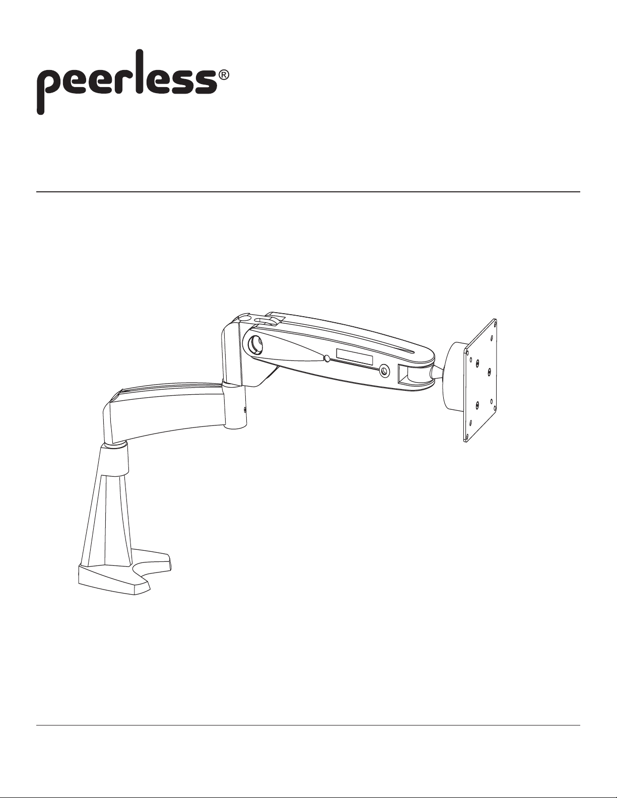
Installation and Assembly:
LCT Series LCD Arm
Model: LCT 101
Supports 10" to 22" screens
Max Load Capacity: 25 lbs (11kg)
3215 W. North Ave. • Melrose Park, IL 60160 • (800) 729-0307 or (708) 865-8870 • Fax: (708) 865-2941 • www.peerlessmounts.com
ISSUED: 03-21-05 SHEET #: 090-9103-5 07-10-08
Note: Read entire instruction sheet before you start installation and assembly.
WARNING
• Do not begin to install your Peerless product until you have read and understood the instructions and warnings
contained in this Installation Sheet. If you have any questions regarding any of the instructions or warnings, please
call Peerless customer service at 1-800-729-0307.
• Make sure that the desk will safely support the combined load of the equipment and all attached hardware
and components.
• Never exceed the Maximum Load Capacity of 25 lb (1 1 kg).
• Always use an assistant or mechanical lifting equipment to safely lift and position equipment.
• Tighten screws firmly , but do not overtighten. Overtightening can damage the items, greatly reducing their
holding power.
• For safety reasons, the gas strut of the LCD Arm product was pre-adjusted in the factory to a lowest force for the
prevention of arm body recoil during installation.
• During the installation, beware of the arm body recoil when attaching or detaching the LCD monitor to the LCD Arm.
When changing LCD panels in the LCD Arm, please always readjust the gas strut to a lowest force level to control the
recoil of the arm body . The LCD arm gas strut has been adjusted with the reserved force to load the original LCD
panel, and the LCD Arm body will be recoiled when det aching the LCD panel directly without adjusting the gas strut.
• Do not attempt to disassemble, service or modify the product yourself.
• Use only a slightly damp cloth to clean the Arm surface. Never use flammable solvents like alcohol, benzene,
thinner, etc.
Table of Contents
Parts List..............................................................................................................................................................................3
Installation to desk with clamp option ...................................................................................................................................4
Installation to desk with bolt option .......................................................................................................................................4
Installing without extension arm............................................................................................................................................5
Installing extension arm ........................................................................................................................................................5
Monitor Attachment ..............................................................................................................................................................6
Cable Management ...............................................................................................................................................................7
Adjustment ...........................................................................................................................................................................7
For customer service call (800) 729-0307 or (708) 865-8870.
2 of 7
ISSUED: 03-21-05 SHEET #: 090-9103-5 07-10-08
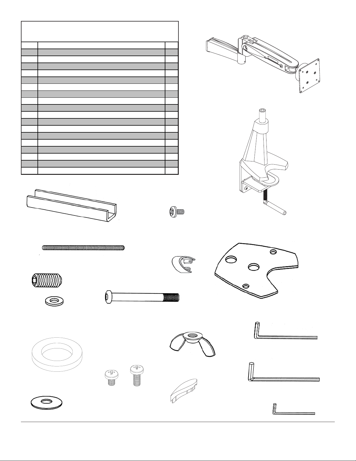
Parts L ist
Description Qty.
desk bas e assembl y 1
A
arm as s embly 1
B
plas t i c cap 1
C
plas t i c spac er 1
D
round head cap screw 1
E
M8 washer 1
F
M8 disk spring washer 1
G
set screw 1
H
M5 hex wrench 1
I
M2. 5 hex wrench 1
J
base cus hi on with double sided adhesive 1
P
u-bracket 1
Q
M8 threaded rod 1
R
wing nut 1
S
M4 hex wrench 1
T
M4 x 6 mm screw 4
U
M4 x 10 mm screw 4
V
M3 screws 2
W
cabl e c l ip 1
X
B
A
H
D
F
R
U
Q
V
E
W
X
P
T
S
I
C
G
3 of 7
J
ISSUED: 03-21-05 SHEET #: 090-9103-5 07-10-08
Installation to Desk
WARNING
• Make sure that the supporting surface will safely support the combined load of the equipment and all attached
hardware and components.
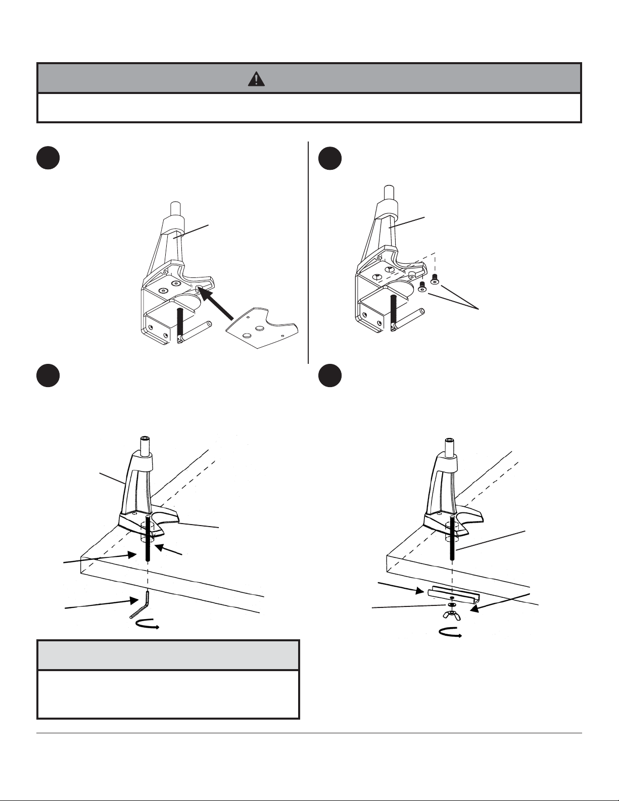
Installation to desk with clamp option
Attach base cushion (P) to desk base assembly (A)
1
by the double sided adhesive tape as shown below.
Clamp desk base assembly to desk by tightening
down clamp.
skip to step four
A
P
Drill a 12 mm hole through the desk.
2 3
Attach base cushion (P) to desk base assembly (A)
and place directly on top of the bolting hole. Tighten
the M8 threaded rod (R) through the bolting hole
using the M4 hex wrench (T).
Installation with bolt option
1
Remove two flat head screws located underneath
desk base assembly (A) using M5 hex wrench (I).
A
FLA T HEAD
SCREWS
Place u-bracket (Q) and washer (F) onto the M8
threaded rod (R) and tighten with wing nut (S).
A
P
BOL TING HOLE
R
T
CAUTION
• Do not tighten screws with excessive force.
Overtightening can cause damage to mount. Tighten
screws to 40 in. • lb (4.5 N.M.) maximum torque.
4 of 7
R
Q
S
F
ISSUED: 03-21-05 SHEET #: 090-9103-5 07-10-08
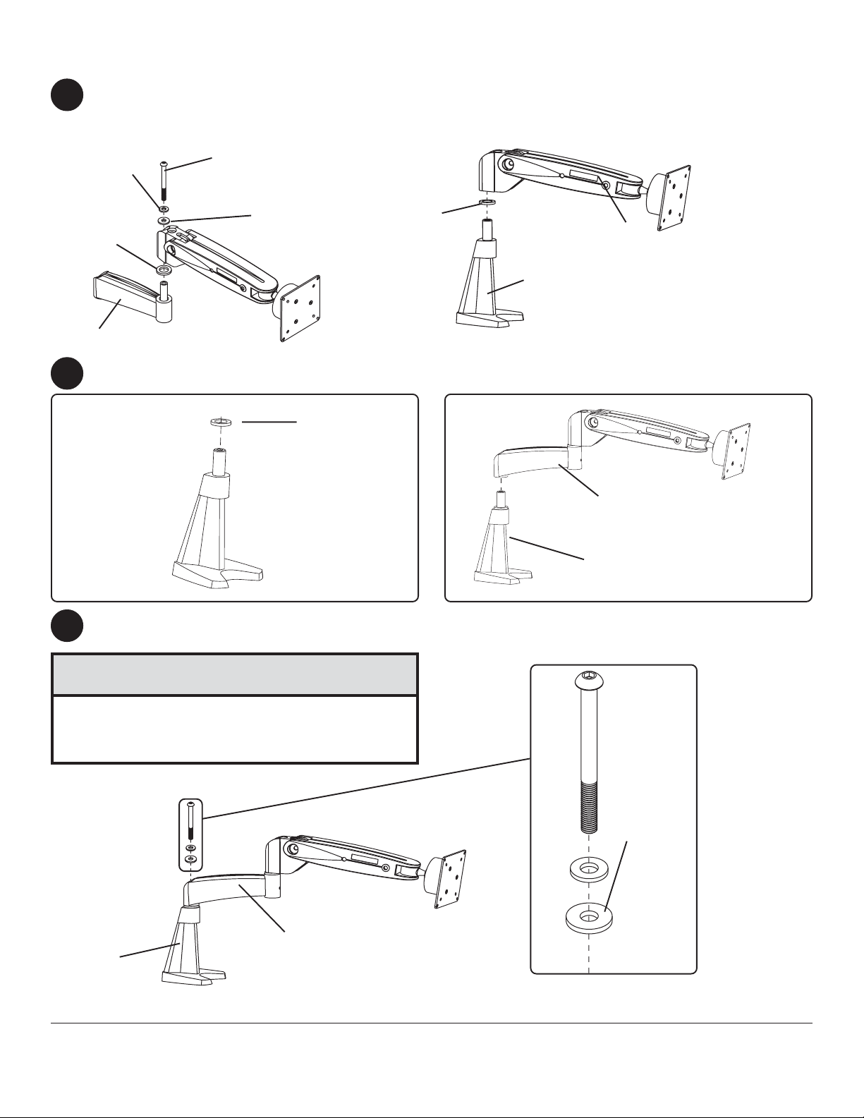
Installing without extension arm (Optional)
Remove plastic cap, not shown, exposing round head cap screw. Use M5 hex wrench (I) to remove round head cap
4
screw, M8 washer , and disk spring washer .
Place plastic spacer and arm assembly (B) onto the main shaft of the desk base (A) as shown in fig. 4.1.
M8 WASHER
PLASTIC
SP ACER
ROUND HEAD CAP
SCREW
DISK SPRING
WASHER
PLASTIC
SP ACER
A
fig. 4.1
EXTENSION ARM
Place plastic spacer (D) and extension arm (B) onto the main shaft of the desk base (A) as shown.
5
D
B
B
A
Insert round head cap screw (E) M8 washer (F) and disk spring washer (G) into extension arm (B) as shown.
6
Tighten with the M5 hex wrench (I).
CAUTION
• Do not tighten screws with excessive force.
Overtightening can cause damage to mount. Tighten
screws to 40 in. • lb (4.5 N.M.) maximum torque.
F
B
A
E
CONVEX
SIDE
G
5 of 7
ISSUED: 03-21-05 SHEET #: 090-9103-5 07-10-08
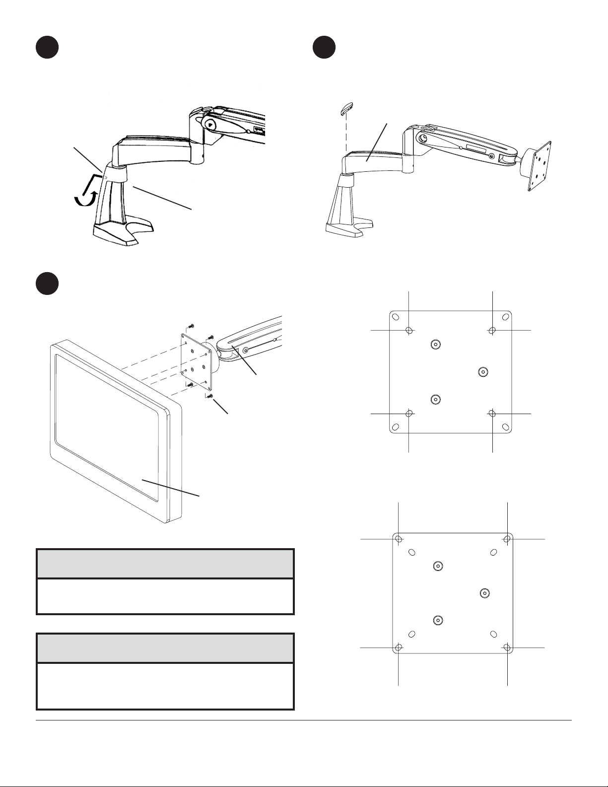
Place set screw (H) into the back of desk base
7
(A). Tighten with the M2.5 hex wrench (J).
Snap plastic cap (C) into top of arm assembly
8
(B).
C
B
H
J
A
Installing monitor
Mount the LCD monitor directly to the front plate of arm assembly (B) using the M4 x 10 mm phillips screws (V) or
9
M4 x 6mm phillips screws (U).
B
U or V
LCD MONITOR
CAUTION
• It is important to always use the mounting screws
provided by the manufacturer of the LCD monitor.
CAUTION
(Vesa 75 mm x 75 mm)
• Do not tighten screws with excessive force.
Overtightening can cause damage to screen. Tighten
screws to 40 in. • lb (4.5 N.M.) maximum torque.
6 of 7
(Vesa 100 mm x 100 mm)
ISSUED: 03-21-05 SHEET #: 090-9103-5 07-10-08
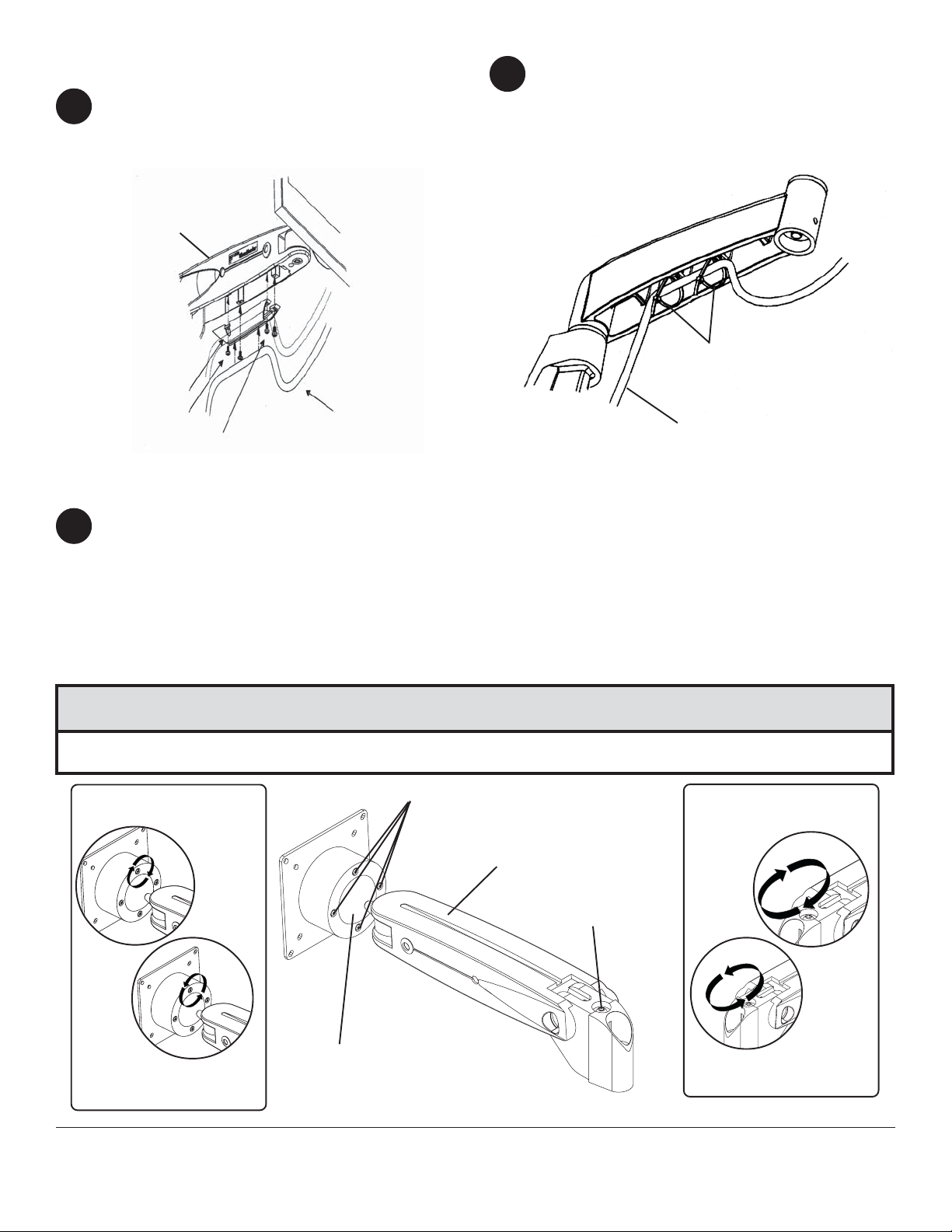
Cable management
Route monitor cables through the cable mount at the
10
bottom of arm assembly (B).
Note: T o allow free motion of monitor and arm, leave
sufficient slack in the cables.
If extension arm is installed, route monitor cables
11
through two 4" x 2.5 mm cable ties, as shown.
Note: T o allow free motion of monitor and arm and
extension, leave sufficient slack in the cables.
Secure cables by tightening the cable tie.
B
CABLE TIES
CABLE
MOUNT
M3 SCREWS
M4 SCREWS
Adjustment
Note: Depending on the weight of the LCD monitor, adjustment may be required to the ball joint mechanism. When
12
performing the adjustments, the arm must be in a horizontal position.
If the monitor does not hold its position or it is too tight, adjust the four tensioning screws located around the ball
joint cover of arm assembly (B). To tighten, adjust the tension clockwise. T o loosen adjust counter clockwise.
(fig. 12.1)
Adjustment to the arm assembly may also be required if the arm tends to drift down or rise up. The adjustment
screw is located at the back of the arm (B). Adjust using the M5 wrench (I). To decrease tension, adjust the
tension clockwise. T o increase tension adjust counter clockwise. (fig. 12.2)
CABLE
CABLE
CAUTION
• T o prevent damage, remove hex wrench before releasing the arm from the horizontal position.
CLOCKWISE
(INCREASE TENSION)
COUNTER CLOCKWISE
(DECREASE TENSION)
BALL COVER JOINT
fig. 12.1
TENSIONING SCREWS
B
ADJUSTMENT SCREW
7 of 7
All other brand and product names are trademarks or registered trademarks of their respective owners.
COUNTER CLOCKWISE
fig. 12.2
ISSUED: 03-21-05 SHEET #: 090-9103-5 07-10-08
© 2008 Peerless Industries, Inc. All rights reserved.
CLOCKWISE
(DECREASE TENSION)
(INCREASE TENSION)
 Loading...