

Installation and Assembly - Monitor Desktop Stand
A
Models: LCH-100
IMPORTANT! Read entire instruction sheet before you start installation and assembly.
IMPORTANT! The product is made to support screens with a Vesa compliant hole pattern.
For safe mounting, mounting screws must turn at least three times in the screen inserts.
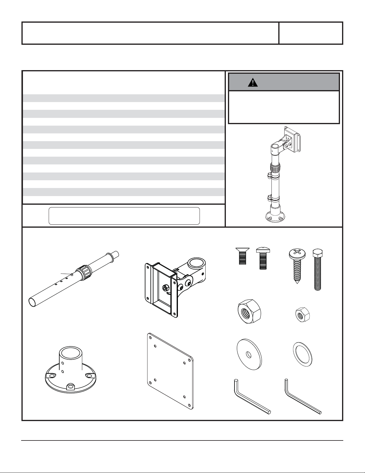
Parts List
Description Qty. Part #
telescopic pedestal 1 091-1088
B pivot head 1 091-1090
C mounting base 1 091-1089
D adapter plate 1 095-1100
M4 x 8mm countersink screw
E
M4 x 10mm phillips screw
F
wood screw #14 x 1
G
H hex bolt 1 -
I hex nut 1 -
J M4 x 0.7mm nut 4 530-1082
K pressure plate 1 -
L nylon washer 1 540-1636
M 4mm allen wrench 2 560-0072
N 3mm allen wrench 1 560-0073
NOTE: You may not use all hardware provided.
NOTE: Some parts may not appear exactly as illustrated.
LCH-100
520-1795
4
520-1796
4
510-9159
4
MAX Load Capacity:
25 lb (11.4KG)
WARNING
SPRING LOADED PRODUCT
• Only release lock ball when screen is
installed. Do not place chin or object
above pole when releasing lock ball.
LCH-100
LOCK BALL
C
A
B
D
E
M
K
F
G
H
I
J
L
N
2300 White Oak Circle • Aurora, Il 60502 • (800) 865-2112 • Fax: (800) 359-6500 • www.peerless-av.com
ISSUED: 09-30-02 SHEET #: 090-9085-6 07-23-13
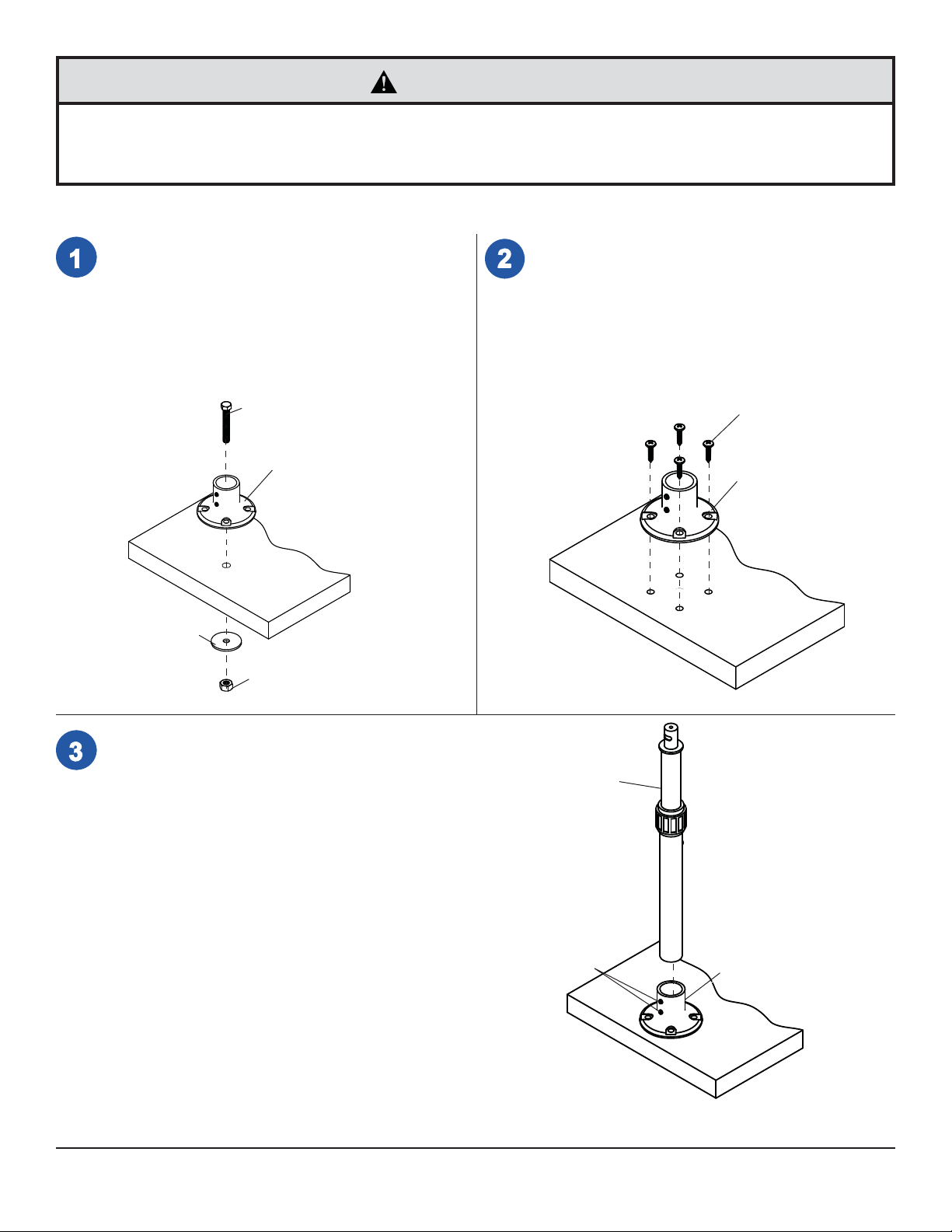
CAUTION
• Mount must be installed on wood and/or wood composition surfaces of at least 3/4" thick. However, the installer
must ensure that the mounting surface will safely hold the combined weight of the mount and the screen. See other
mounting requirements below.
There are two methods of installation. Follow step 1 for installation using hex bolt and pressure plate or
step 2 using four wood screws.
Mark hole on desktop for positioning mount.
Drill one 1/2" dia. hole through desktop. Attach
mounting base (C) to desktop using hex bolt (H),
pressure plate (K), and hex nut (I). Tighten nut
using proper sized wrench.
Important! Mount is to be installed onto desktops
3/4" to 1-5/8" thick only! For thicker mounting
surfaces, you may have to provide your own
hardware.
H
C
Use four holes on mounting base (C) to mark holes
on desktop for positioning mount. Drill four 3/16"
dia. holes through desktop. Attach mounting base
(C) to desktop using four wood screws (G).
G
C
DESKTOP
K
I
Insert telescopic pedestal (A) into mounting base (C).
Tighten set screws where shown with 3 mm allen wrench (N).
SET SCREWS
DESKTOP
A
C
2 of 5
ISSUED: 09-30-02 SHEET #: 090-9085-6 07-23-13

To install to a VESA 75 mm standard LCD monitor,
attach pivot head (B) to back of LCD monitor using four
M4 x 10 mm phillips screws (F) as shown.
Skip to step 6.
B
F
GENERIC LCD SCREEN
To install to a VESA 100 mm standard LCD monitor, attach
adapter plate (D) to pivot head (B) using four M4 x 8 mm
phillips screws (E) and four M4 x 0.7mm nuts (J) as shown in
detail 1. Attach pivot head (B) to back of LCD monitor using
four M4 x 10 mm phillips screws (F) as shown in detail 2.
E
D
B
J
GENERIC LCD SCREEN
B
F
DETAIL 1 DETAIL 2
3 of 5
ISSUED: 09-30-02 SHEET #: 090-9085-6 07-23-13

Place nylon washer (L) and pivot head (B) on top pin
of telescopic pedestal (A) as shown. To restrict rotation
of LCD screen to 90°, lineup rear set screw with slot
and tighten where shown in detail 3 using 3 mm allen
wrench (N). To completely restrict rotation, tighten rear
set screw using 3 mm allen wrench (N).
SLOT
REAR SET
SCREW
B
SET SCREWS
L
A
DETAIL 3
Turn tube nut counterclockwise to loosen. Gently hold pivot head
(B) down with one hand, and gently press on lock ball with the other
hand. Lock ball must be inserted into outer tube to obtain up and down
movement. Do not insert lock ball all the way into the inner tube.
Adjust to desired height making sure to locate lock ball into one the
four holes as shown.
NOTE: Setting the lock ball in the lowermost hole requires the removal
of the inner white plastic ring. To do this set the lock back in a
different hole. Slowly unscrew the tube nut until it comes off threads.
Remove the white plastic ring inside the tube nut. Retighten the tube
nut. Adjust the height until the lock ball reaches the lowermost hole.
B
INNER TUBE
TUBE NUT
LOCK BALL
A
OUTER TUBE
BACK VIEW
4 of 5
ISSUED: 09-30-02 SHEET #: 090-9085-6 07-23-13

For tilt adjustment use one 4 mm allen wrench (M) to
hold socket screw in place and the other 4 mm allen
wrench (M) to turn the socket screw clockwise to tighten
and counterclockwise to loosen as shown.
Turn screen clockwise by hand for landscape or portrait
orientation.
M
SOCKET
SCREW
M
Route cord(s) through cable clips for cord management.
Note: Ensure the cords have enough slack for proper clearance
and function.
5 of 5
All other brand and product names are trademarks or registered trademarks of their respective owners.
CABLE
CLIPS
MONITOR
CORD(S)
ISSUED: 09-30-02 SHEET #: 090-9085-6 07-23-13
© 2013 Peerless Industries, Inc. All rights reserved.
 Loading...