


Installation and Assembly:
Ceiling mount for LCD screens up to 29"
Models: LCC-18, LCC-18-S, LCC-36, LCC-36-S, LCC-36-W
Patent Pending
Features:
• Comes in two adjustable height ranges (in 1" increments): 18"-30" and
36"-48".
• -5° to +20° adjustable tilt.
• Screen can be mounted in standard position or face-down.
• Portrait or landscape orientation.
• Ceiling plate included.
• Hardware included for wood or concrete installations.
• Theft resistant security fasteners included.
• VESA® 75/100 mm compliant (Non-VESA adapter offered separately).
• Comes in black or silver. LCC 36-W offered in white.
• 360° swivel action.
2300 White Oak Circle • Aurora, Il 60502 • (800) 865-2112 • Fax: (800) 359-6500 • www.peerless-av.com
Max UL Load Capacity: 40 lb (18.1 kg)
ISSUED: 09-27-04 SHEET #: 100-9004-8 10-08-12

Note: Read entire instruction sheet before you start installation and assembly.
WARNING
• Do not begin to install your Peerless product until you have read and understood the instructions and warnings
contained in this Installation Sheet. If you have any questions regarding any of the instructions or warnings, for US
customers please call Peerless customer care at 1-800-865-2112, for all international customers, please contact
your local distributor.
• This product should only be installed by a qualifi ed professional.
• Make sure that the ceiling will safely support the combined load of the equipment and all attached hardware and
components.
• Never exceed the Maximum UL Load Capacity. See page 1.
• If mounting to wood ceiling joists, make sure that mounting screws are anchored into the center of the joists. Use of
an "edge to edge" stud fi nder is highly recommended.
• Always use an assistant or mechanical lifting equipment to safely lift and position equipment.
• Tighten screws fi rmly, but do not overtighten. Overtightening can damage the items, greatly reducing their holding
power.
Accessories
• Lightweight Adjustable Suspended Ceiling Kit (CMJ 500)
• Lightweight Suspended Ceiling Kit (CMJ 455)
• Accessory Pack for CMJ 455 (ACC455)*
• Lightweight Cathedral Ceiling Plate (ACC912)*
• Unistrut or Structural Ceiling Plates (CMJ 300, CMJ 310)*
• Anti-Vibration Ceiling Plates (ACC845)*
• I-Beam Clamps (ACC558, ACC559)
• Truss Ceiling Adapter (ACC557)*
• Unistrut Adapter (ACC550)
• Escutcheon Ring (ACC640)*
• Round Ceiling Plate (ACC570)
• Cord Wrap (ACC852(W)(S))*
• Fixed Length 1 1/2" Extension Columns
(EXT models)
• Adjustable Length 1 1/2" Extension Columns
(ADJ models)
• Extension Column Stabilizer Kit (ACC050)*
• Extension Column Connector (ACC109)
• 1/2" Threaded Rod (ACC820)*
• Threaded Rod Adapter (ACC810)*
• Non-VESA Adapter Plates (LC models)*
*not evaluated by UL
Tools Needed for Assembly
• stud fi nder ("edge to edge" stud fi nder is recommended)
• phillips screwdriver
• drill with 5/16", 3/8", and 5/32" drill bits
Table of Contents
Parts List.................................................................................................................................................................................3
Installation to Wood Joist Finished Ceilings, Exposed Wood Joists, or Wood Beam Ceilings ...............................................4
Installation to Concrete Ceilings .............................................................................................................................................5
Installing Reducer ...................................................................................................................................................................6
Flush Mount Installation..........................................................................................................................................................7
Installation to Threaded Rod ..................................................................................................................................................7
Installation to Extension Column ............................................................................................................................................8
Installation to Lightweight Suspended Ceiling Plate ...............................................................................................................9
Attaching Tilt Bracket to LCD Screen ................................................................................................................................. 10
Installation of screen in the Vertical Position ........................................................................................................................11
Installation of screen in the Horizontal Position ................................................................................................................... 12
2 of 12
ISSUED: 09-27-04 SHEET #: 100-9004-8 10-08-12

A
Parts List
Description Qty. Part # Part # Part # Part #
tube assembly 1 055-1520 055-4520 055-1521 055-4521
ceiling plate 1 580-1042 580-4042 580-1042 580-4042
B
tilt bracket 1 055-1551 055-4551 055-1551 055-4551
C
reducer 1 580-1009 580-4009 580-1009 580-4009
D
#14 x 2.5" wood screw 2 5S1-015-C03 5S1-015-C04 5S1-015-C03 5S1-015-C04
E
M5 x 12 mm socket pin screw 4 520-1064 520-2064 520-1064 520-2064
F
4 mm security allen wrench 1 560-9646 560-9646 560-9646 560-9646
G
concrete anchor 2 590-0320 590-0320 590-0320 590-0320
H
10-32 x 3/8" socket set screw 1 520-1127 500-2018 520-1127 500-2018
I
hex wrench 1 560-1034 560-1034 560-1034 560-1034
J
M4 x 10 mm socket pin screw 4 520-1060 520-2060 520-1060 520-2060
K
M4 x 12 mm serrated washer head socket pin screw 4 510-1079 510-2079 510-1079 510-2079
L
M4 x 20 mm socket pin screw 4 520-1061 520-2163 520-1061 520-2163
M
#10-32 x 3/16" slotted set screw 1 520-1187 520-2187 520-1187 520-2187
N
retaining spacer 4 590-5005 590-5003 590-5005 590-5003
O
M5 x 10 mm socket pin F-type screw 1 520-1164 520-2031 520-1164 520-2031
P
cable tie 3 590-1168 590-1168 590-1168 590-1168
Q
LCC-18 LCC-18S LCC-36 LCC-36S
A
BC
E
H
I
N
F
K
D
G
J
L
M
O
P
Q
3 of 12
ISSUED: 09-27-04 SHEET #: 100-9004-8 10-08-12

Installation to Wood Joist Finished Ceilings,
Exposed Wood Joists, or Wood Beam Ceilings
Drill two 5/32" (4 mm) dia. holes to a minimum
1
depth of 2.5" (64 mm). Attach ceiling plate (B)
with two #14 x 2.5" (6 mm x 65 mm) wood
screws (E) as shown using 3/8" (10 mm) socket
wrench. Tighten wood screws (E) so ceiling
plate (B) is fi rmly attached.
WARNING
• Tighten wood screws so that ceiling plate is fi rmly
attached, but do not overtighten. Overtightening can
damage the screws, greatly reducing their holding
power.
• Never tighten in excess of 80 in • lb (9 N.M.).
• Make sure that mounting screws are anchored into
the center of the joist. The use of an "edge to edge"
stud fi nder is highly recommended.
Skip to step 2 on page 6.
WOOD
JOIST
CEILING
B
E
4 of 12
E
ISSUED: 09-27-04 SHEET #: 100-9004-8 10-08-12
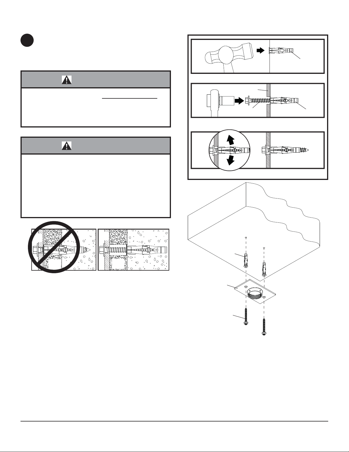
Installation to Concrete Ceilings
Drill two 5/16" (8 mm) dia. holes to a minimum depth
1
of 2.5" (64 mm). Attach ceiling plate (B) using two
concrete anchors (H) and #14 x 2.5" wood screws (E)
as shown in Illustration A and 1, 2, and 3 (below).
Tighten all fasteners.
1
concrete
surface
H
WARNING
• Tighten wood screws fi rmly, but do not overtighten.
Overtightening can damage the bolt, greatly reducing
its holding power.
• Never tighten in excess of 80 in • lb (9 N.M.).
WARNING
• Concrete anchors are not intended for attachment to
concrete wall covered with a layer of plaster, drywall,
or other fi nishing material. If mounting to concrete
wall covered with plaster/drywall is unavoidable, plaster/drywall (up to 5/8" thick) must be counterbored as
shown below. If plaster/drywall is thicker than 5/8",
custom fasteners must be supplied by installer (not
evaluated by UL).
INCORRECT CORRECT
wall
plate
concrete
wall
plate
concrete
Drill holes and insert anchors (H).
E
B
H
2
Place plate (B) over anchors (H) and secure with screws (E).
3
Tighten all fasteners.
CONCRETE CEILING
CUTAWAY VIEW
plaster/
dry wall
plaster/
dry wall
H
B
E
Illustration A
5 of 12
ISSUED: 09-27-04 SHEET #: 100-9004-8 10-08-12

Installing Reducer
Thread reducer (D) onto tube assembly (A) until tight.
2
Insert set screw (I) into reducer as shown in fi gure 2.1.
Tighten screw using hex wrench (J). Note: Set screw
(I) is used to jam against the threads of tube assembly
to prevent any excess movement.
To adjust height of tube assembly (A), remove socket
pin screw and two lock washers using 4 mm security
allen wrench (G) and adjust to desired height as
shown in fi gure 2.2.
D
I
fi g. 2.1
A
LOCK WASHERS
SOCKET PIN SCREW
A
fi g. 2.2
6 of 12
ISSUED: 09-27-04 SHEET #: 100-9004-8 10-08-12
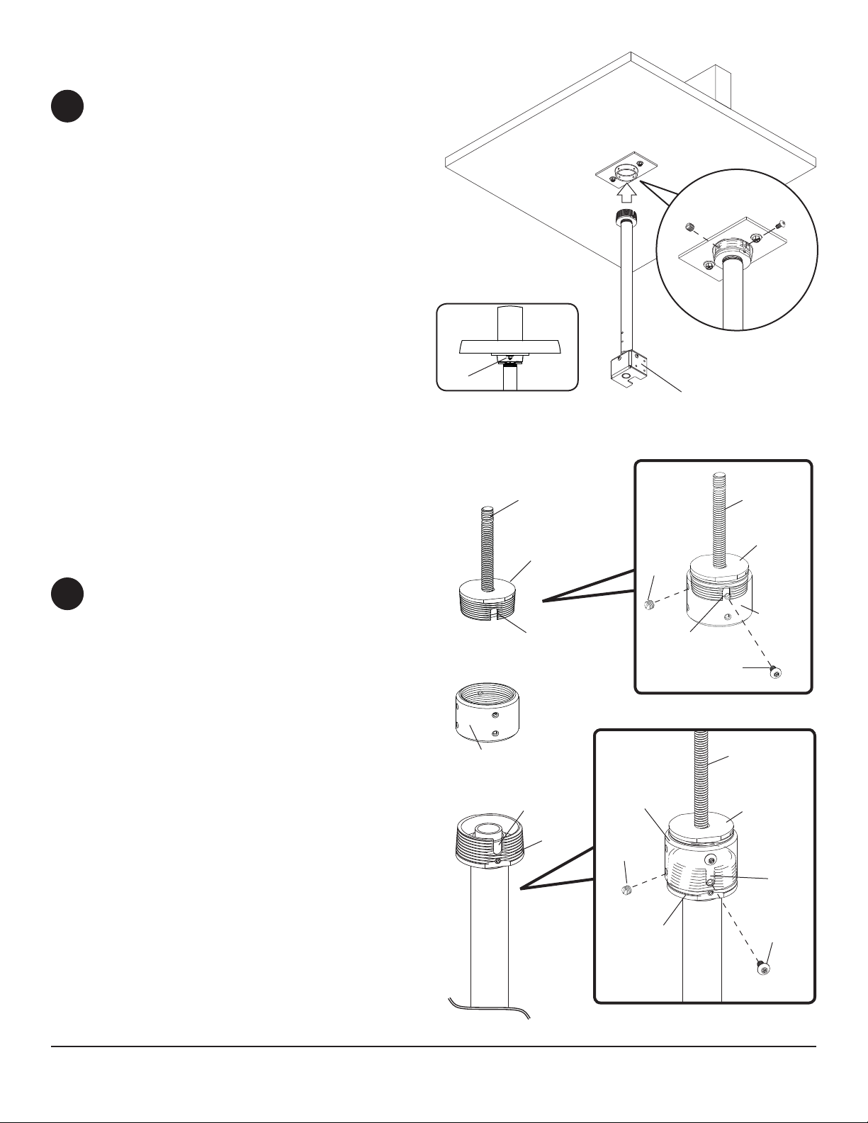
Flush Mount Installation
Screw reducer (D) into ceiling plate (B) until notch
3
in reducer is aligned with one of the four holes in
ceiling plate and set screw (I) is at least partially
covered by ceiling plate as shown in fi gure 3.1.
Secure reducer with one M5 x 10 mm F-type
socket pin screw (P) using security allen wrench
(G) as shown in fi gure 3.2. Note: Slotted set
screw (N) is used to jam against the threads of
the reducer to prevent any excess movement of
the tube assembly (A). Do not overtighten screw;
overtightening screw will damage threads making
it diffi cult to separate the products.
Skip to step 4 on page 10.
I
fi g. 3.1
B
D
N
A
P
fi g. 3.2
Installation to
Threaded Rod
Accessory ACC810 (not evaluated by UL),
threaded rod adapter, is required.
Screw threaded rod adapter (ACC810) into extension
3
column connector (ACC109). Align slot in threaded
rod adapter with one of the top holes in extension
column connector. Insert and tighten one #10-32 x
3/8" socket pin screw provided with extension column
connector through extension column connector into
slot on threaded rod adapter using 4 mm security
allen wrench (G). See fi gure 3.3.
Align slot in reducer (D) to one of the bottom holes
in extension column connector. Insert and tighten
one #10-32 x 3/8" socket pin screw provided with
extension column connector through extension
column connector into slot in reducer. See fi gure 3.4.
Note: Slotted set screws provided with extension
column connector are used to jam against the
threads of each connecting joint to prevent any
excess movement. Do not overtighten screws;
overtightening screws will damage threads making
it diffi cult to separate the products.
Skip to step 4 on page 10.
1/2 -13 THREADED
ROD
ACC810 (SOLD
SEPARATELY)
SLOT
ACC109
(SOLD SEPARATELY)
SLOT
D
ACC109
SET
SCREW
SET
SCREW
SLOT
D
THREADED
ROD
ACC810
ACC109
SOCKET
PIN
SCREW
fi g. 3.3
THREADED
ROD
ACC810
SLOT
SOCKET
PIN
SCREW
7 of 12
fi g. 3.4
ISSUED: 09-27-04 SHEET #: 100-9004-8 10-08-12

Installation to Extension Column
Screw extension column (EXT or ADJ
3
Series) to ceiling plate (B). Align the
notch with one of the four holes in the
ceiling plate and secure extension
column with a M5 x 10 mm socket pin
screw (P) using security allen wrench
(G). See fi gure 3.5.
Note: Slotted set screw (N) is used to
jam against the threads of the reducer
to prevent any excess movement of the
extension column. Do not overtighten
screw; overtightening screw will damage
threads making it diffi cult to separate the
products.
Screw extension column connector
(ACC109) to extension column. Align
slot in extension column with one of the
top holes in extension column connector.
Insert and tighten one #10-32 x 3/8"
socket pin screw provided with projector
through extension column connector into
slot on extension column using security
allen wrench (G). See fi gure 3.6.
EXTENSION COLUMN
(EXT or ADJ Series)
Sold Separately
SLOT
B
P
N
B
EXTENSION
COLUMN
fi g. 3.5
EXTENSION
COLUMN
Screw reducer (D) to extension column
connector. Align reducer to one of
the bottom holes in extension column
connector. Insert and tighten one #1032 x 3/8" socket pin screw provided with
connector through extension column
connector into slot in reducer using
security allen wrench (G). See fi gure 3.7.
Note: Slotted set screws provided with
extension column connector are used
to jam against the threads of each
connecting joint to prevent any excess
movement. Do not overtighten screws;
overtightening screws will damage
threads making it diffi cult to separate the
products.
Skip to step 4 on page 10.
EXTENSION COLUMN
CONNECTOR (SOLD
SEPARATELY)
D
SLOT
SET SCREW
ACC109
ACC109
SET SCREW
SLOT
SOCKET PIN
SCREW
fi g. 3.6
EXTENSION
COLUMN
SLOT
ACC850 - EXTENSION COLUMN
CONNECTOR WITH CORD MANAGEMENT
- MAY BE USED IN PLACE OF EXTENSION
COLUMN CONNECTOR. (SOLD
SEPARATELY)
8 of 12
D
SOCKET PIN
SCREW
fi g. 3.7
ISSUED: 09-27-04 SHEET #: 100-9004-8 10-08-12

Installation to Lightweight Suspended Ceiling Plate
Refer to instruction sheet for lightweight
3
suspended ceiling plate (CMJ 455) for
attachment of ceiling plate to ceiling.
Screw extension column (EXT or ADJ
Series) to
retaining collar in ceiling
tray. Align the notch with one of the
four holes in retaining collar and secure
extension column with one M5 x 10
mm socket pin screw (P) using security
allen wrench (G). See fi gure 3.8.
Note: Slotted set screw (N) is used to
LIGHTWEIGHT SUSPENDED
CEILING PLATE (SOLD
SEPARATELY)
RETAINING COLLAR
P
jam against the threads of the reducer
to prevent any excess movement of the
extension column. Do not overtighten
screw; overtightening screw will
N
EXTENSION
COLUMN (SOLD
SEPARATELY)
damage threads making it diffi cult to
separate the products.
fi g. 3.8
Screw extension column connector
to extension column. Align slot in
extension column with one of the top
holes in extension column connector.
EXTENSION
COLUMN
Insert and tighten one 10-32 x 3/8
socket pin screw provided with
connector through extension column
connector into slot on extension column
using security allen wrench. See fi gure
EXTENSION COLUMN
(EXT or ADJ Series)
Sold Separately
SET SCREW
3.9.
Screw reducer (D) to extension column
connector. Align slot in reducer to one
of the bottom holes in extension column
connector. Insert and tighten one 10-32
x 3/8 socket pin screw provided with
connector through extension column
connector into slot in reducer using
security allen wrench. See fi gure 3.10.
Note: Slotted set screws provided with
extension column connector are used
to jam against the threads of each
connecting joint to prevent any excess
movement. Do not overtighten screws;
EXTENSION COLUMN
CONNECTOR (SOLD
SEPARATELY)
ACC109
SLOT
SLOT
SOCKET PIN
SCREW
fi g. 3.9
EXTENSION
COLUMN
SLOT
overtightening screws will damage
threads making it diffi cult to separate
SET SCREW
the products.
D
ACC109
ACC850 - EXTENSION COLUMN
CONNECTOR WITH CORD
MANAGEMENT - MAY BE USED IN PLACE
OF EXTENSION COLUMN CONNECTOR.
(SOLD SEPARATELY)
9 of 12
SOCKET PIN
D
SCREW
fi g. 3.10
ISSUED: 09-27-04 SHEET #: 100-9004-8 10-08-12

Attaching Tilt Bracket to LCD Screen
Note: This product is designed to accommodate screens with VESA
4
mounting, please make sure that mounting screws turn at least three complete turns in the screen inserts.
FOR VESA 75 MOUNTING PATTERN:
1) Choose hole pattern indicated below. 2) Attach tilt bracket (C) to back of screen using four M4 x 10 mm screws
(K) as indicated below. 3) If hole pattern is in a pocket, attach tilt bracket to back of screen using four M4 x 20
mm screws (M) and four retaining spacers (O) as indicated below. Tighten all security screws with security allen
wrench (G).
C
BOTTOM OF SCREEN
®
compliant hole patterns. For safe
For screens with a hole
pattern in a pocket,
spacers (O) go between
tilting bracket (C) and
screen.
Note: LCD screen may
appear slightly different
than illustrated.
FOR VESA 100 MOUNTING PATTERN:
1) Choose hole pattern indicated below. 2) Attach tilt bracket (C) to back of screen using four M4 x 10 mm screws
(K) as indicated below. Tighten all security screws with security allen wrench (G).
Note: If installing LCD screen model Sharp® LC-13E1U, LC-15E1U, LC-20E1U, or if you don't get three complete
turns in the screen inserts, use four M4 x 12 mm screws (L) instead of four M4 x 10 mm screws (K).
C
BOTTOM OF SCREEN
Note: LCD screen may
appear slightly different
than illustrated.
10 of 12
ISSUED: 09-27-04 SHEET #: 100-9004-8 10-08-12

Installation of Screen in the Vertical Position
Insert two M5 x 12 mm screws (F) into column bracket of tube assembly (A) (see fi gure 5.1). Leave approximately
5
3/16" of thread exposed (see fi gure 5.2).
3/16"
COLUMN
BRACKET
EXPOSED
THREAD
F
fi g. 5.1 fi g. 5.2
Hook tilt bracket (C) onto column bracket (see fi gure 6.1). Then secure with two M5 screws (F) (see fi gure 6.2).
6
Adjust tilt (20° forward and 5° back) and swivel to desired position. Tighten all screws using security allen wrench (G).
Note: Cable ties (Q) are provided for optional cord management along tube.
WARNING
• Always use an assistant or mechanical lifting equipment to safely lift and position the LCD screen.
COLUMN
C
BRACKET
F
fi g. 6.1 fi g. 6.2
11 of 12
ISSUED: 09-27-04 SHEET #: 100-9004-8 10-08-12

Installation of Screen in the Horizontal Position
Insert two M5 x 12 mm screws (F) into column bracket of tube assembly (A) (see fi gure 5.1). Leave approximately
5
3/16" of thread exposed (see fi gure 5.2).
COLUMN
BRACKET
3/16"
EXPOSED
THREAD
fi g. 5.1 fi g. 5.2
Hook tilt bracket (C) onto column bracket (see fi gure 6.1). Secure with two M5 screws (F) (see fi gure 6.2). Adjust
6
tilt (20° forward and 5° back) and swivel to desired position. Tighten all screws using security allen wrench (G).
Note: Cable ties (Q) are provided for optional cord management along tube.
WARNING
• Always use an assistant or mechanical lifting equipment to safely lift and position the LCD screen.
F
fi g. 6.1
C
COLUMN
BRACKET
F
fi g. 6.2
12 of 12
All other brand and product names are trademarks or registered trademarks of their respective owners.
ISSUED: 09-27-04 SHEET #: 100-9004-8 10-08-12
© 2012, Peerless Industries, Inc. All rights reserved.
 Loading...