

Page 1
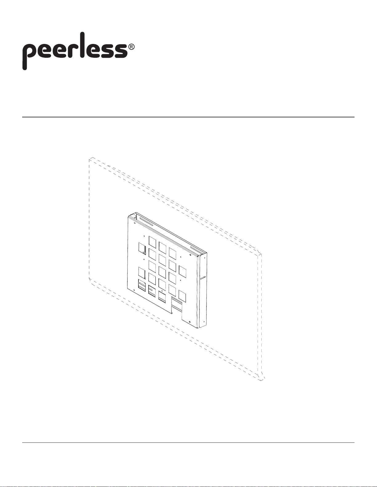
Installation and Assembly:
Flat \ Tilt Wall Mount for VESA 400x400
Model: HT642
Max Load Capacity: 100 lb (45.4 kg)
3215 W. North Ave. • Melrose Park, IL 60160 • (800) 729-0307 or (708) 865-8870 • Fax: (708) 865-2941 • www.peerlessmounts.com
ISSUED: 08-18-08 SHEET #: 125-9012-4 12-19-13
Page 2
Note: Read entire instruction sheet before you start installation and assembly.
WARNING
• Do not begin to install your Peerless product until you have read and understood the instructions and warnings
contained in this Installation Sheet. If you have any questions regarding any of the instructions or warnings, please
call Peerless customer service at 1-800-729-0307.
• This product should only be installed by a qualified professional.
• Make sure that the supporting surface will safely support the combined load of the equipment and all attached hardware and components.
• Never exceed the Maximum Load Capacity of 100 lb (45.4 kg).
• If mounting to wood wall studs, make sure that mounting screws are anchored into the center of the studs. Use of an
"edge to edge" stud finder is highly recommended.
• Always use an assistant or mechanical lifting equipment to safely lift and position equipment.
• Tighten screws firmly, but do not overtighten. Overtightening can damage the items, greatly reducing their holding
power.
• This product was designed and intended to be mounted to the following supporting surfaces checked below with the
hardware included in this product as specified in the installation sheet. To mount this product to an alternative supporting surface, contact Peerless customer care at 1-800-865-2112.
• This product was designed to be installed on the following wall construction only;
WALL CONSTRUCTION ADDITIONAL HARDW ARE REQUIRED
x Wood Stud None
x Wood Beam None
x Solid Concrete None
x Cinder Block None
x Metal Stud None
Brick Contact Customer Service
Other or unsure? Contact Customer Service
Tools Needed for Assembly
• stud finder ("edge to edge" stud finder is recommended)
• phillips screwdriver
• drill with 5/16" and 5/32" drill bits
• 5/16" socket wrench
Table of Contents
Parts List .............................................................................................................................................................................. 3
Attaching Adapter Bracket to Screen.................................................................................................................................... 4
Installation to Wood Stud Wall ............................................................................................................................................. 5
Installation to Solid Concrete and Cinder Block Wall ............................................................................................................ 6
Installation to Metal Stud ...................................................................................................................................................... 7
Attaching Mounting Bracket Using Hook On Option ............................................................................................................. 8
Attaching Mounting Bracket Using Tilt Option ...................................................................................................................... 9
For customer care call (800) 729-0307 or (708) 865-8870.
2 of 9
ISSUED: 08-18-08 SHEET #: 125-9012-4 12-19-13
Page 3
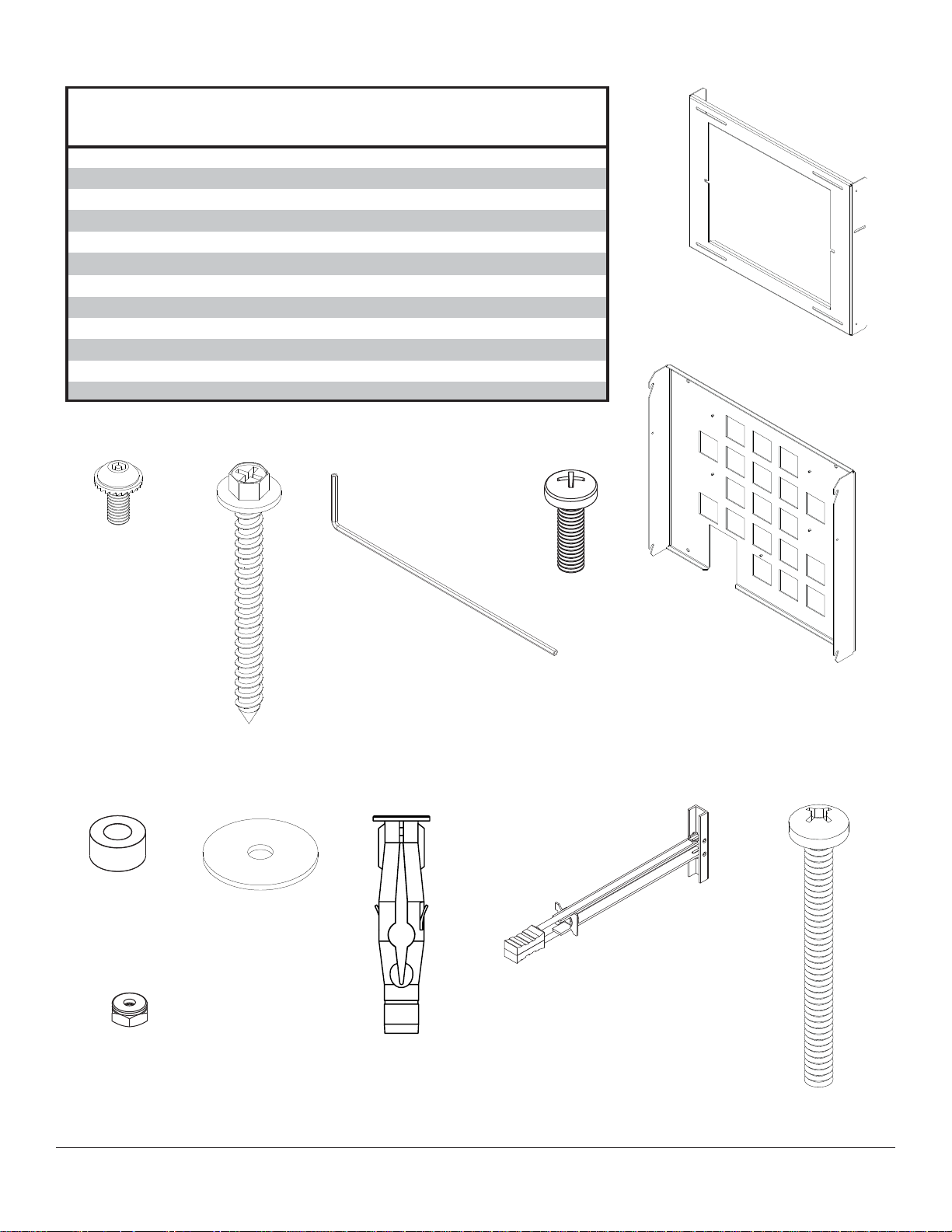
Before you start make sure all parts listed are included with your product.
PARTS LIST
A
wall plate
B
adapter bracket
C
#14 x 2.5 round phillips screw
D
M5 x 12 mm socket pin serrated washer head screw
E
#14 x 2.5 wood screw
F
4 mm security allen wrench
G
M6 x 20 mm phillips pan screw
spacer
H
washer
I
concrete anchor
J
toggler
K
6-32 NYLOCK nut
L
Some parts may appear slightly different than illustrated.
D
F
1 201-1601
1 201-1725
4 520-9521
6 510-1064
6 5S1-015-C03
1 560-1129
4 520-9402
1 590-1050
4 540-1008
6 590-0320
4 560-9708
4 530-1006
GE
A
B
H I J
L
3 of 9
K
ISSUED: 08-18-08 SHEET #: 125-9012-4 12-19-13
C
Page 4

Attaching Adapter Bracket to Screen
Attach adapter bracket (B) to back of plasma screen using four M6 x 20 mm phillips screws (G).
1
400 mm
400 mm
B
Screen
WARNING
• Do not overtighten. Overtightening may cause perma-
For installing HCS5610 Pay-Per-View Box, see step 2.
For installing LST -4100B IP Interface Module, see step 3.
Installing HCS5610 Pay-Per-View Interface Box with Integrated HD Tuner
2
to Attachment Plate
Note: Rubber grommets on the mounting tabs of HCS5610 will have to be removed before installing.
Place HCS5610 onto the threaded studs on adapter plate (A) and secure with three 6-32 nylock nuts (L) using a
5/16" socket wrench.
L
nent damage to the screen. Torque to 26-35 in • lb
(30-40 kg • cm).
SCREEN
LG MODEL HCS5610
(WITH THREE MOUNTING
TABS ATTACHED)
4 of 9
B
ISSUED: 08-18-08 SHEET #: 125-9012-4 12-19-13
Page 5

Installing LST-4100B IP Interface Module to Attachment Plate
3
Note: Rubber grommets on the mounting tabs of LST-4100B will have to be removed before installing.
Place LST-4100B onto the threaded studs on adapter plate (A) and secure with four 6-32 nylock nuts (L) using a 5/16"
socket wrench.
SCREEN
L
B
LG MODEL LST-4100B
(WITH FOUR MOUNTING
TABS ATTACHED)
Installation to Wood Stud Walls
Use a stud finder to locate center of studs.
4
For mounting to 16" centers
Using mounting bracket (A) as a template, drill four 5/32" (4 mm) dia. holes to a minimum depth of 2.5" (64
mm). Attach mounting bracket (A) to centers of wood studs using four #14 x 2.5" wood screws (E) and four
washers (I) as shown below.
A
E
I
5 of 9
ISSUED: 08-18-08 SHEET #: 125-9012-4 12-19-13
Page 6

Installation to Solid Concrete and Cinder Block Wall
WARNING
5
A
5/16"
E I
WARNING
WARNING
not
(8
1
J
Drill holes and insert anchors (J ).
E
A
I
2
Place plate (A) over anchors (J ) and secure with screws (E
concrete
surface
J
J
).
3
Tighten all fasteners.
plate
CUTAWAY VIEW
wall
plaster/
dry wall
INCORRECT CORRECT
concrete
wall
plate
plaster/
dry wall
concrete
6 of 9
fig 5.3
J
I
E
A
fig 5.4
4 12-19-13
Page 7

Installation to Metal Stud
WARNING
• Drywall must be 1/2" or thicker, and metal stud must be 24 gauge or thicker.
• Make sure that the wall will safely support the combined load of the equipment and all attached hardware and
components.
Using a stud finder, locate and mark the edges of the metal stud used in mounting this product. Use of an edge to
6
edge stud finder is highly recommended. Use a level to draw a level, vertical line down the center of the stud. Level
wall plate, and mark the center of the six mounting holes. Make sure that the mounting holes are on the stud
centerline. Drill six 1/2" holes through drywall and metal studs. Note: It may be necessary to drill 5/32" pilot holes
prior to drilling 1/2" holes.
WARNING
• Product must be mounted through drywall that has a
minimum thickness of 1/2" and into metal studs, 26
gauge or heavier.
• Make sure that togglers are anchored into the center
of the stud. The use of an "edge to edge" stud finder
is highly recommended.
6-1
6-2
6-3
6-4
6-5
Pivot end of toggler (K).
K
Push into hole.
Rotate toggler (K)
clockwise to wedge it
against inside walls
of metal stud.
Slide plastic cap
forward while pulling
back firmly on ring.
Break off excess.
7 of 9
ISSUED: 08-18-08 SHEET #: 125-9012-4 12-19-13
Page 8

Attaching Mounting Bracket Using Hook On Option
Attach four M5 x 12 mm serrated washer head
7
socket pin screws (D) to the holes on the sides of
mounting bracket (A) using the 4mm security allen
wrench (F) provided.
Position slots of adapter brackets (B) onto the four
7-1
M5 x 12 mm serrated washer head socket pin
screws (D) attached to mounting bracket (A).
SLOT
D
A
B
D
A
D
To secure adapter brackets (B) to mounting bracket (A), attach two M5 x 12 mm serrated washer head socket pin
7-2
screws (D) into the threaded inserts of adapter brackets (B), and through the slots on the sides of mounting bracket
(A). Tighten with the 4 mm security allen wrench (F).
For tilt option skip to Step 8
D
B
D
A
8 of 9
ISSUED: 08-18-08 SHEET #: 125-9012-4 12-19-13
Page 9

Mounting Bracket Using Tilt Option
Remove top two M5 x 12 mm socket pin serrated washer head screws (D) attached to wall plate (A). Loosen two
8
M5 x 12 mm socket pin serrated washer head screws (D) in slot as shown in Detail 1. Once desired tilt is
established tighten two M5 x 12 mm socket pin serrated washer head screws (D) in slots.
D
D
D
B
D
SLOT
A
Detail 1
9 of 9
All other brand and product names are trademarks or registered trademarks of their respective owners.
ISSUED: 08-18-08 SHEET #: 125-9012-4 12-19-13
© 2010 Peerless Industries, Inc. All rights reserved.
Peerless is a registered trademark of Peerless Industries, Inc.
 Loading...