

Page 1
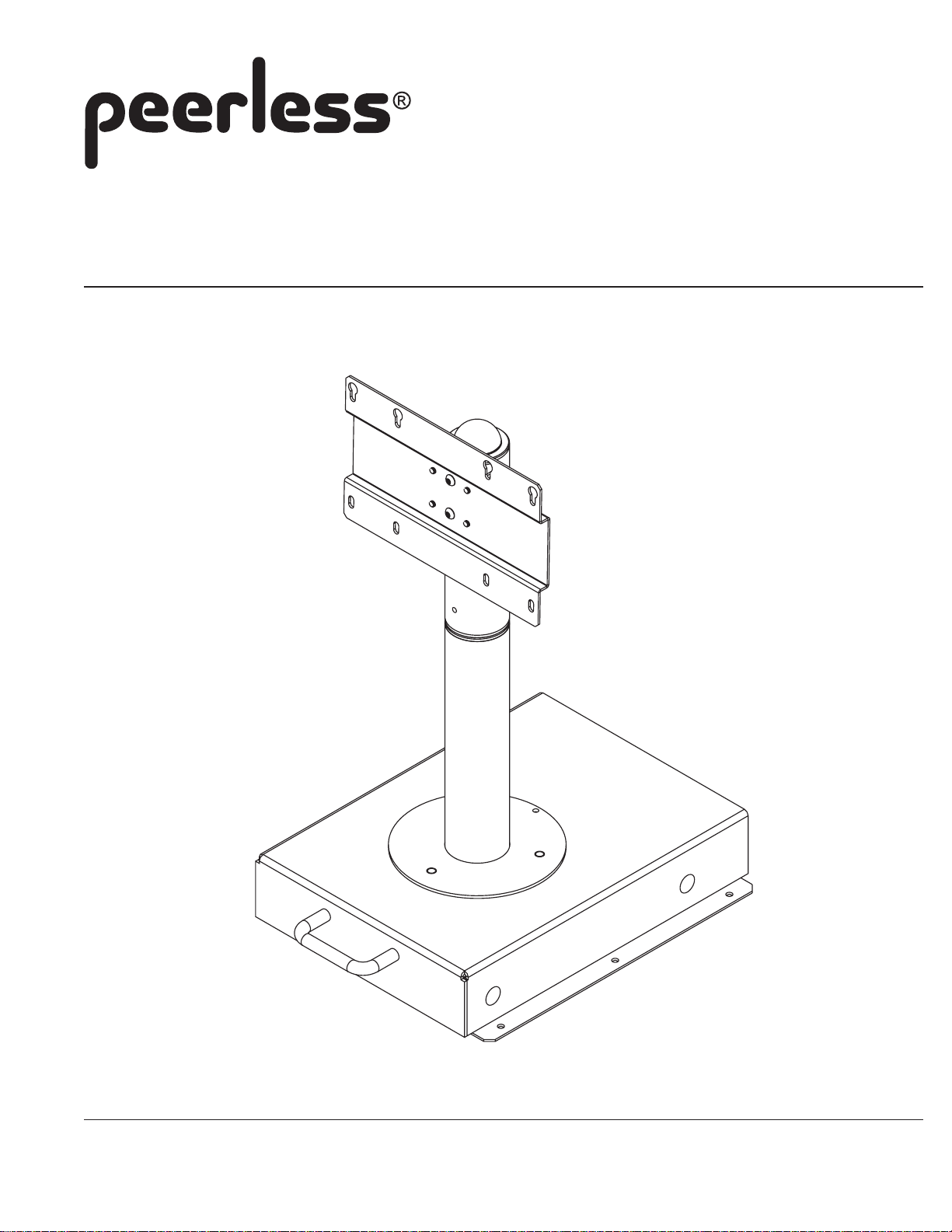
Installation and Assembly
LCD Slideout Swivel Stand
Model: HS432-001, HS432-001-GB
Max Load Capacity: 50 lbs (22.7 kg)
3215 W. North Ave. • Melrose Park, IL 60160 • (800) 865-2112 or (708) 865-8870 • Fax: (708) 865-2941 • www.peerlessmounts.com
ISSUED: 09-07-07 SHEET #: 124-9108-1
Page 2
Note: Read entire instruction sheet before you start installation and assembly.
WARNING
• Do not begin to install your Peerless product until you have read and understood the instructions and warnings
contained in this Installation Sheet. If you have any questions regarding any of the instructions or warnings, please
call Peerless customer care at 1-800-865-2112.
• This product should only be installed by a qualified professional.
• Make sure that the supporting surface will safely support the combined load of the equipment and all attached
hardware and components.
• Never exceed the Maximum Load Capacity of 50 lbs (22.7 kg).
• Always use an assistant or mechanical lifting equipment to safely lift and position equipment.
• Tighten screws firmly, but do not overtighten. Overtightening can damage the items, greatly reducing their holding
power.
Table of Contents
Parts List .................................................................................................................................................................. 3
Installing Tube Assembly .......................................................................................................................................... 4
Installation to Cabinet ............................................................................................................................................... 5
Installing Screen ....................................................................................................................................................... 6
For customer service call (800) 865-2112 or (708) 865-8870.
2 of 6
Visit the Peerless Web Site at www.peerlessmounts.com For customer care call 1-800-865-2112 or 708-865-8870.
ISSUED: 09-07-07 SHEET #: 124-9108-1
Page 3

IMPORTANT! Read entire instruction sheet before you start installation and assembly.
Parts List
Description Qty. Pa rt #
slideout base assembly 1 090-0466 090-0568
A
adapter plate assembly 1 090-0467 090-0569
B
adapter support tube 1 090-1458 090-P1458
C
swivel tube 1 090-1461 090-P1461
D
base tube 1 090-1464 090-P1464
E
M4 x 12 mm socket pin serrated washer head screw 4 510-1079 510-1079
F
1/4-20 x 1/2'' socket pin security head screw 2 520-1054 520-1054
G
M5 x 10 mm socket pin security head screw 2 520-1164 520-1164
H
10-16 x 3/4'' penta-pin screw 6 520-9258 520-9258
I
1/4-20 nylock nut 3 530-9413 530-9413
J
ball endcap 1 590-1021 590-1021
K
bushing 4 590-1088 590-1088
L
spacer 1 590-1120 590-1120
M
penta-pin tool 1 520-9249 520-9249
N
4 mm security allen wrench 1 560-9646 560-9646
O
Note: Some parts may appear slightly different than illustrated.
HS432-001 HS432-001-GB
A
B
F
G
L
Before you start make sure all parts listed are included with your product.
Visit the Peerless Web Site at www.peerlessmounts.com For customer care call 1-800-865-2112 or 708-865-8870.
H
M
I
3 of 6
C
N
J
E
D
K
O
ISSUED: 09-07-07 SHEET #: 124-9108-1
Page 4

Extend slideout assembly (A) and insert premounted studs of base tube (E) into top holes of slideout assembly.
1
Secure base tube to slideout assembly using three 1/4-20" nylock nuts (J) as shown figure 1.1.
Insert two bushings (L) into top and bottom of base tube (E) as shown figure 1.2.
PREMOUNTED
STUDS
L
E
E
A
A
fig. 1.1
J
Insert two bushings (L) into adapter support tube (C). Place spacer (M) onto pilot pin of swivel tube (D). Insert
2
swivel tube (D) from underneath slideout assembly, through base tube (E) and into adapter tube (C). Ensure pilot
pin of swivel tube (D) extends into swivel slot of slideout assembly (A) as shown in figure 2.2. Insert end cap (K)
into top bushing (L).
Align holes on adapter support tube (C) and swivel tube (D) and secure with two 1/4-20 x 1/2" socket pin security
head screws (G) as shown in figure 2.3.
L
fig. 1.2
K
L
C
L
SWIVEL
SLOT
PILOT PIN
D
E
fig. 2.2
A
C
G
D
M
fig. 2.1
Visit the Peerless Web Site at www.peerlessmounts.com For customer care call 1-800-865-2112 or 708-865-8870.
PILOT PIN
4 of 6
fig. 2.3
ISSUED: 09-07-07 SHEET #: 124-9108-1
Page 5

Close slideout assembly (A) and place in the center of mounting surface of cabinet. Align handle of slideout
3
assembly flush with front of cabinet as shown in figure 3.1.
Using the slideout assembly (A) as a template, mark the center of the six mounting holes. Extend slideout
assembly and attach to cabinet using six 10-16 x 3/4" penta-pin screws (I), thighten using Penta-pin tool (N).
I
A
HANDLE ALIGNS FLUSH WITH
FRONT OF CABINET
fig. 3.1
Align holes of adapter plate assembly (B) with adjustment holes of adapter support tube (C) to the desired height
4
of screen. Secure adapter plate assembly (B) to adapter support tube (C) with two M5 x 10 mm socket pin
security head screws (H).
NOTE: Cabinet not shown for clarity
B
A
fig. 3.2
C
ADJUSTMENT HOLES
H
5 of 6
Visit the Peerless Web Site at www.peerlessmounts.com For customer care call 1-800-865-2112 or 708-865-8870.
ISSUED: 09-07-07 SHEET #: 124-9108-1
Page 6

WARNING
• If screws don't get three complete turns in the screen inserts or if screws bottom out and bracket is still not tightly
secured, damage may occur to screen or product may fail.
Thread two M4 x 12 mm socket pin serrated washer head screws (F) into two top mounting holes of
5
screen leaving 1/8" exposed thread as shown in figure 5.1.
Hook screen onto keyhole slots of adapter plate assembly (B) as shown in figure 5.2. Insert two M4 x 12
mm socket pin serrated washer head screws (F) through adapter plate assembly (B) into bottom mounting holes of screen as shown in figure 5.3. Tighten four screws securely.
NOTE: Cabinet not shown for clarity
1/8" SPACE
fig. 5.1
B
F
fig. 5.2
B
F
fig. 5.3
6 of 6
Visit the Peerless Web Site at www.peerlessmounts.com For customer care call 1-800-865-2112 or 708-865-8870.
All other brand and product names are trademarks or registered trademarks of their respective owners.
ISSUED: 09-07-07 SHEET #: 124-9108-1
© 2007, Peerless Industries, Inc. All rights reserved.
 Loading...