

Page 1
PSZ 250 A2
5
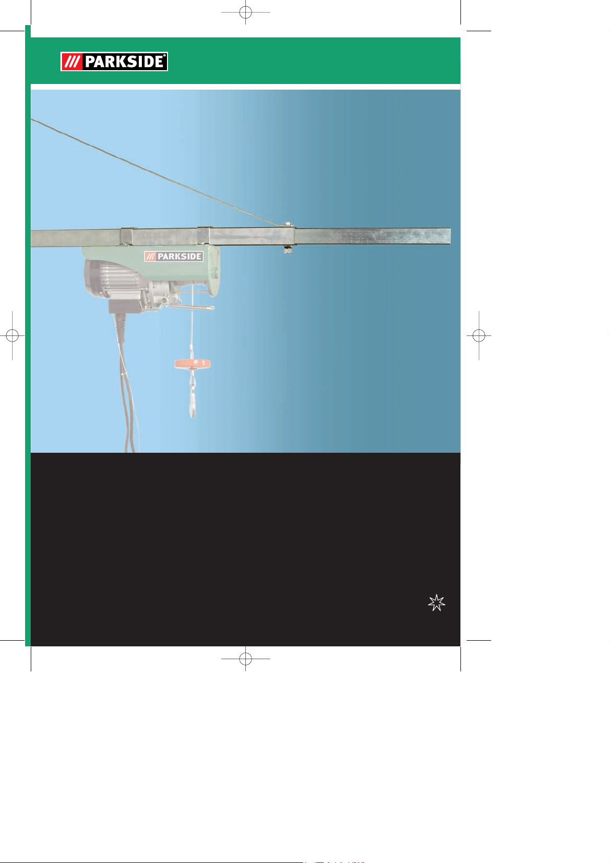
BRAZO GIRATORIO PARA
POLIPASTO DE CABLE
Instrucciones de utilización y de seguridad
Manual de instrucciones original
BRACCIO ORIENTABILE PER
PARANCO SOLLEVATORE
Indicazioni per l’uso e per la sicurezza
Istruzioni per l’uso originali
SCHWENKARM FÜR SEILHEBEZUG
Bedienungs- und Sicherheitshinweise
Originalbetriebsanleitung
SWIVEL ARM FOR CABLE HOIST
Operation and Safety Notes
Original operating instructions
Anleitung_LB5_2255413:_ 21.07.2011 10:31 Uhr Seite 1
Page 2

2
Antes de empezar a leer abra la página que contiene las imágenes y, en seguida, familiarícese con
todas las funciones del dispositivo.
Prima di leggere aprire la pagina con le immagini e prendere confidenza con le diverse funzioni
dell’apparecchio.
Before reading, unfold the page containing the illustrations and familiarise yourself with all functions of
the device.
Klappen Sie vor dem Lesen die Seite mit den Abbildungen aus und machen Sie sich anschließend mit
allen Funktionen des Gerätes vertraut.
ES Instrucciones de utilización y de seguridad Página 7
IT/MT Indicazioni per l’uso e per la sicurezza Pagina 12
GB/MT Operation and Safety Notes Page 17
DE/AT/CH Bedienungs- und Sicherheitshinweise Seite 22
Anleitung_LB5_2255413:_ 21.07.2011 10:31 Uhr Seite 2
Page 3
3
1
2 3
4
5
6
1
(A)
1
7
8
9
10
11
12
13
14
15
16
17
19
2
2 3
A
B
20
18
Anleitung_LB5_2255413:_ 21.07.2011 10:31 Uhr Seite 3
Page 4
4
4 5
8 9
7
6
2
11
4
H=380mm
5
1
10
9
5
2
1
5
8
1
1
3
A
B
Anleitung_LB5_2255413:_ 21.07.2011 10:32 Uhr Seite 4
Page 5
5
10
12 13
11
4
7
4
6
6
17
6
20
19
18
17
4
5
4
5
5
3
14 15
16 14 15
C
Anleitung_LB5_2255413:_ 21.07.2011 10:32 Uhr Seite 5
Page 6
6
20
1100 mm
max. 300 kg
16
18 19
17
16 14 15
750 mm
max. 600 kg
13
5
4
12
6
12
1
3
Anleitung_LB5_2255413:_ 21.07.2011 10:32 Uhr Seite 6
Page 7

ES
7
Índice de contenidos: Página
1. Introducción..................................................................................8
2. Instrucciones de seguridad ..........................................................8
3. Descripción del aparato y volumen de entrega ............................8
4. Uso adecuado .............................................................................8-9
5. Características técnicas ..............................................................9
6. Antes de la puesta en marcha......................................................9
7. Montaje.........................................................................................9-10
8. Mantenimiento, limpieza y pedido de piezas de repuesto.............10
9. Eliminación y reciclaje ..................................................................10
10. Certificado de garantía ................................................................11
La reimpresión o cualquier otra reproducción
de documentos e información adjunta a
productos, incluida cualquier copia, sólo se
permite con la autorización expresa de ISC
GmbH.
Salvo modificaciones técnicas
Anleitung_LB5_2255413:_ 21.07.2011 10:32 Uhr Seite 7
Page 8

8
1. Introducción
¡Atención!
Al usar aparatos es preciso tener en cuenta
una serie de medidas de seguridad para evitar
lesiones o daños. Por este motivo, es preciso
leer atentamente estas instrucciones de uso.
Guardar esta información cuidadosamente
para poder consultarla en cualquier momento.
En caso de entregar el aparato a terceras
personas, será preciso entregarles, asimismo,
el manual de instrucciones.
No nos hacemos responsables de accidentes
o daños provocados por no tener en cuenta
este manual y las instrucciones de seguridad.
2. Instrucciones de seguridad
Es imprescindible tener en cuenta los
siguientes puntos para evitar sufrir accidentes
y lesiones.
No sobrecargue el brazo.
En caso de que esté dañado, no vuelva a
utilizarlo.
Tenga en cuenta que todos los tornillos
estén bien apretados; contrólelos
regularmente por su propia seguridad.
Tenga en cuenta que los pasadores de
aletas estén fijados de forma apropiada en
las perforaciones.
Queda terminantemente prohibido
transportar personas con el torno de cable.
Asimismo, nadie podrá encontrarse situado
bajo el torno de cable o del brazo oscilante.
Este producto no podrá ser utilizado por
aquellas personas que no dispongan de los
conocimientos pertinentes en materia de
seguridad.
La totalidad de las piezas han de ser
comprobadas periódicamente a fin de evitar
cualquier tipo de deformación o deterioro.
¡Tenga en cuenta la máxima carga
permitida! (Véase Características técnicas)
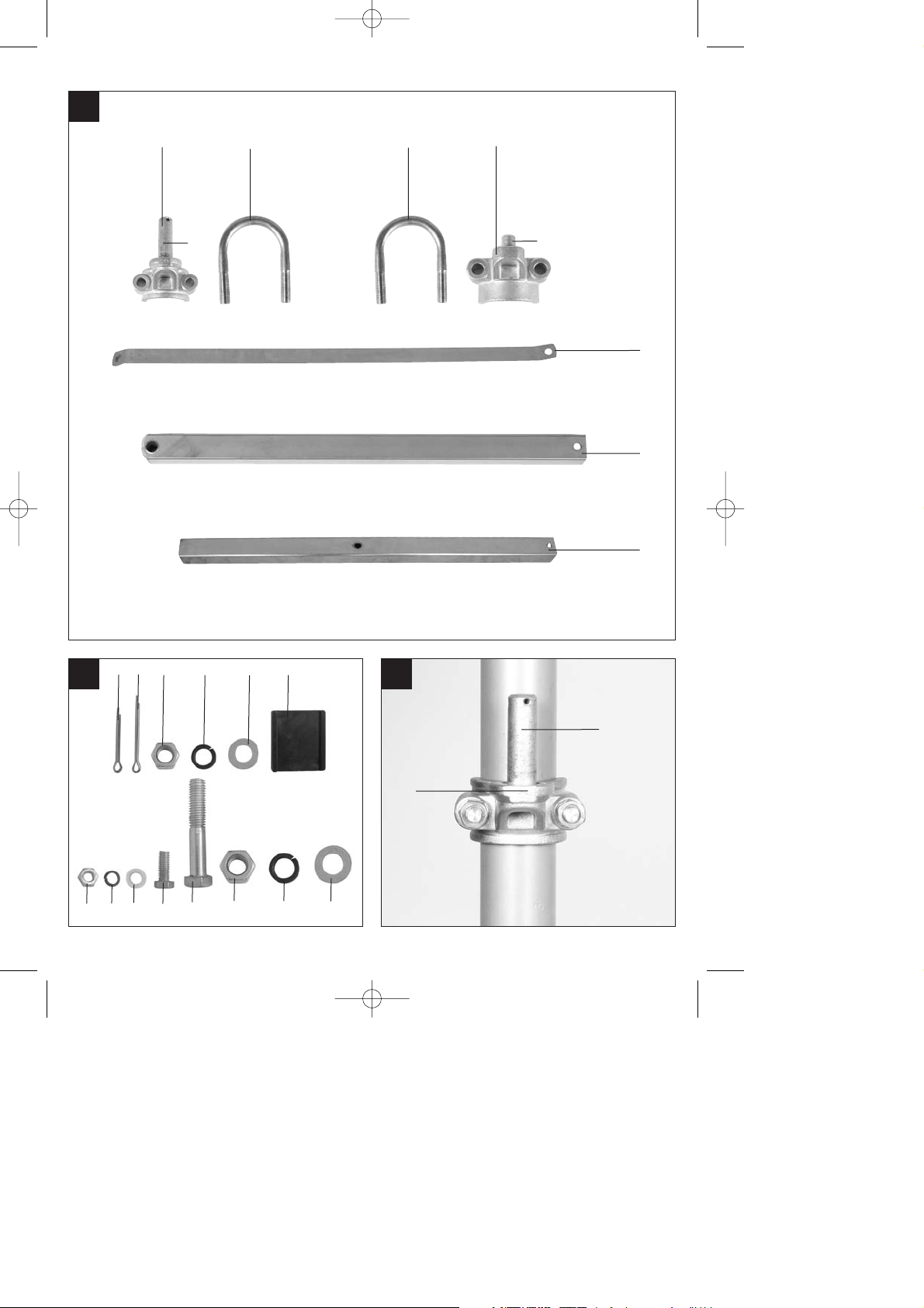
3. Descripción del aparato y
volumen de entrega (fig. 1/2)
1. Manguito de tubo (con pasador de bisagra
grande A)
2. 2 estribos de sujeción para manguitos de
tubo
3. Manguito de tubo (con pasador de bisagra
pequeño B)
4. Brazo de apoyo
5. Brazo de extensión cuadrado 45 x 45 x 1,8
mm
6. Tubo de extensión 40 x 40 x 2,5 mm
7. Pasador de aletas Ø 3 x 45 mm
8. Pasador de aletas Ø 3 x 60 mm
9. 4 tuercas hexagonales M10
10. 4 arandelas elásticas Ø 10
11. 4 arandelas en U Ø 10
12. 2 bases para estribo de sujeción
13. Tuerca hexagonal M8
14. Arandela elástica Ø 8
15. Arandela en U Ø 8
16. Tornillo hexagonal M8 x 15 mm
17. Tornillo hexagonal M 12 x 70 mm
18. Tuerca hexagonal M12
19. Arandela elástica Ø 12
20. Arandela en U Ø 12
4. Uso adecuado
El brazo oscilante sirve para sujetar un torno
de cable. Para ello, es preciso montar el brazo
en una barra de acero bien sujeta y con un
diámetro de 48 mm.
Utilizar la máquina sólo en los casos que se
indican explícitamente como de uso adecuado.
Cualquier otro uso no será adecuado. En caso
de uso inadecuado, el fabricante no se hace
responsable de daños o lesiones de cualquier
tipo; el responsable es el usuario u operario de
la máquina.
Tener en consideración que nuestro aparato
no está indicado para un uso comercial,
industrial o en taller. No asumiremos ningún
tipo de garantía cuando se utilice el aparato en
zonas industriales, comerciales o talleres, así
ES
Anleitung_LB5_2255413:_ 21.07.2011 10:32 Uhr Seite 8
Page 9
ES
9
como actividades similares.
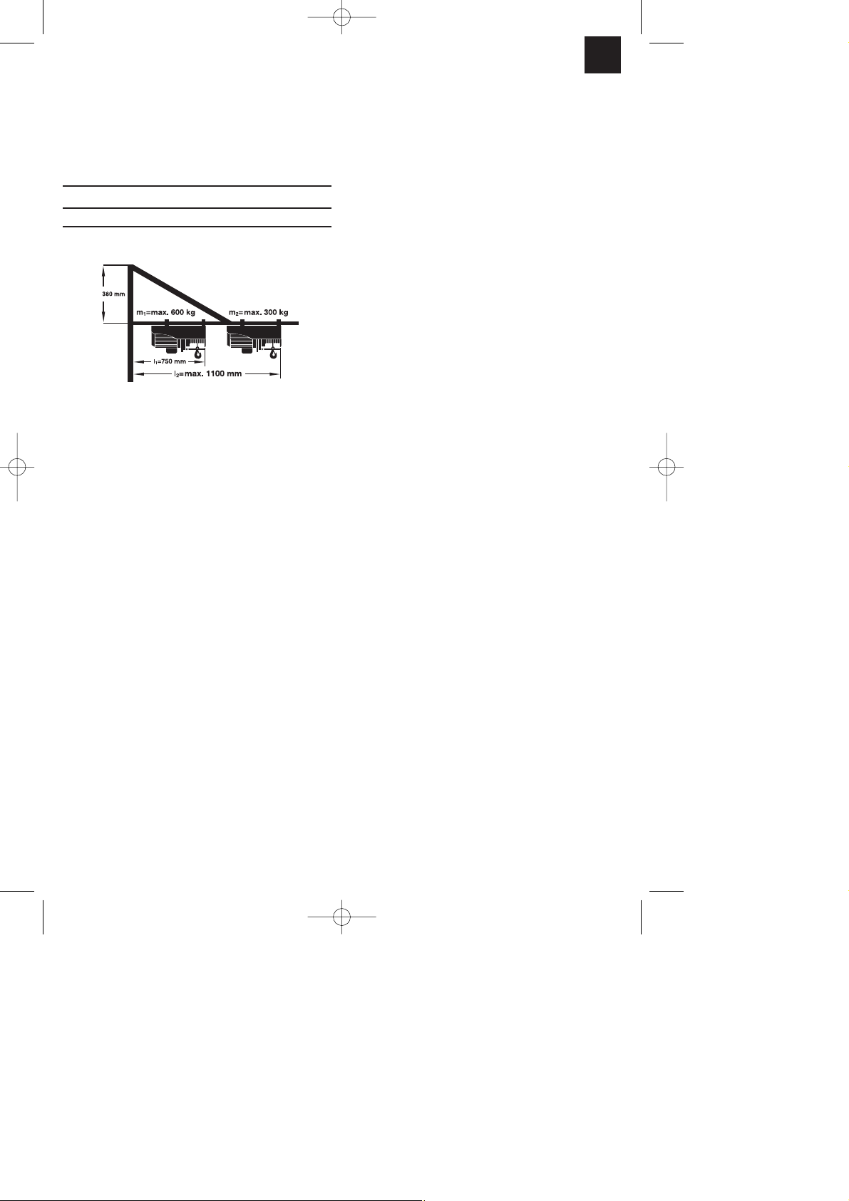
5. Características técnicas:
Volada l: carga máx.:
l1= 750 mm m1= 600 kg
l2= 1100 mm m2= 300 kg
Alcance de giro: máx. 180°
6. Antes de la puesta en marcha
El brazo oscilante sirve de alojamiento para
un torno de cable.
Para fijar el brazo oscilante, se requiere
una barra de acero redonda con un
diámetro de Ø 48 mm, el espesor de pared
ha de ser como mínimo de 3 mm. Tenga
en cuenta que el anclaje de la barra de
acero sea capaz de soportar las fuerzas
que intervengan. Es preciso que se deje
asesorar en un concesionario autorizado.
Esta barra de acero no se incluye en el
volumen de entrega.
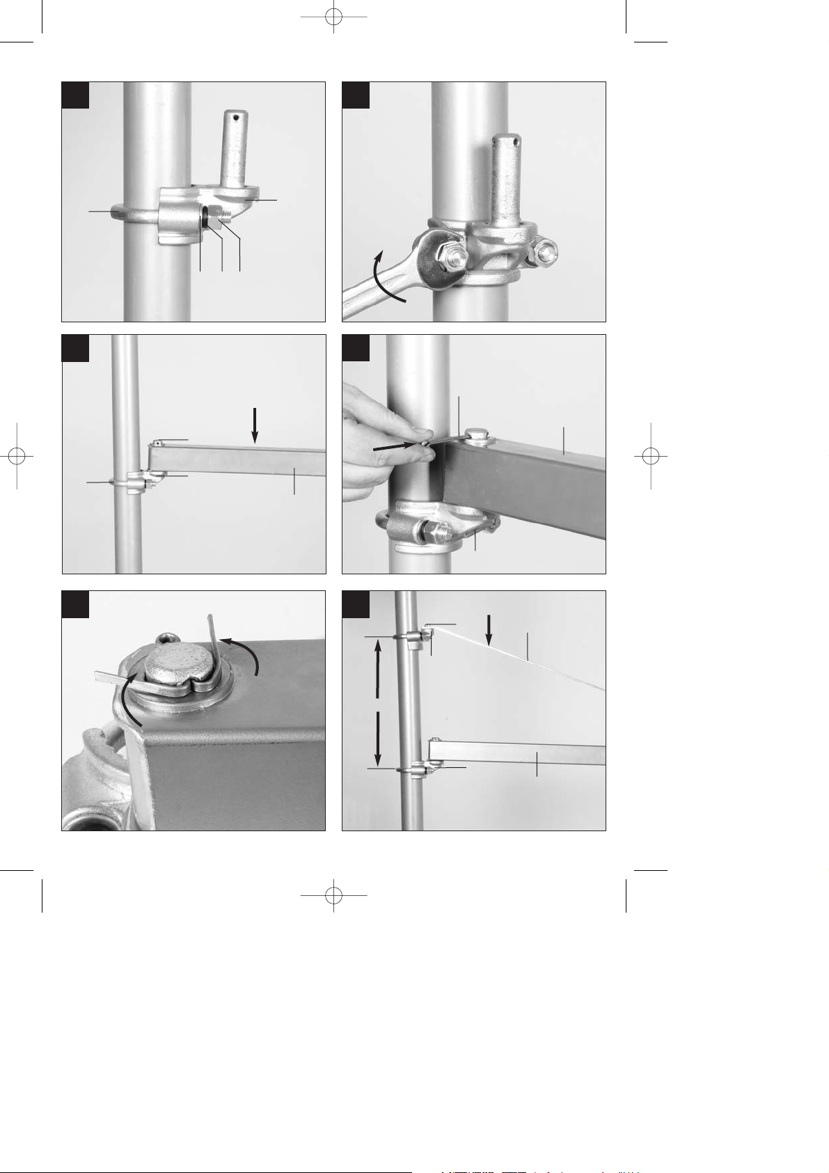
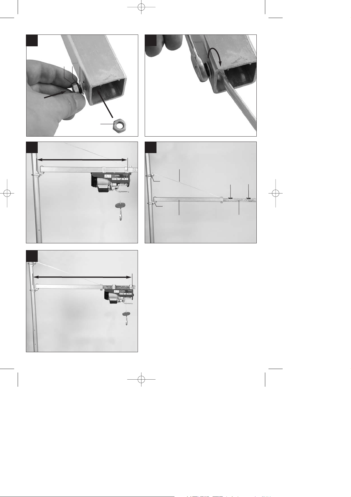
7. Montaje
Fije el manguito de tubo (1) (con pasador
de bisagra grande (A)) a una barra de
acero por medio del estribo de sujeción
para el manguito de tubo (2), las arandelas
(11), las arandelas elásticas (10) y dos
tuercas hexagonales (9) . Antes de apretar
los tornillos, introduzca los manguitos de
tubo (1) a la altura de trabajo deseada del
brazo oscilante (fig. 3-5).
Engrase el pasador de bisagra (A) con
grasa lubricante.
A continuación, cuelgue el brazo de
extensión cuadrado (5) del pasador de
bisagra (A) e introduzca el pasador (8) por
el orificio del pasador de bisagra (A) (fig. 6-
7).
Después, separe ambos lados del pasador
de aletas entre sí doblándolos, de modo
que el pasador de aletas (8) no pueda
saltar del orificio. (Fig. 8)
Fije el manguito de tubo (3) (con un
pasador de bisagra pequeño (B)) a la barra
de acero, de modo análogo al manguito de
tubo (1) situado por encima del brazo de
extensión cuadrado. Oriente aquí la altura
del manguito de tubo superior (3) de modo
que la distancia H entre los dos manguitos
de tubo (1/3) sea exactamente de 380 mm.
A continuación, introduzca el brazo de
apoyo (4) en el orificio mayor del pasador
de bisagra (B) del manguito de tubo (3).
Introduzca el pasador de aletas (7) por el
orificio del pasador de bisagra (B) y separe
ambos lados del pasador (7) doblándolos,
de forma que el pasador (9) no pueda
saltar del orificio (fig. 9-10).
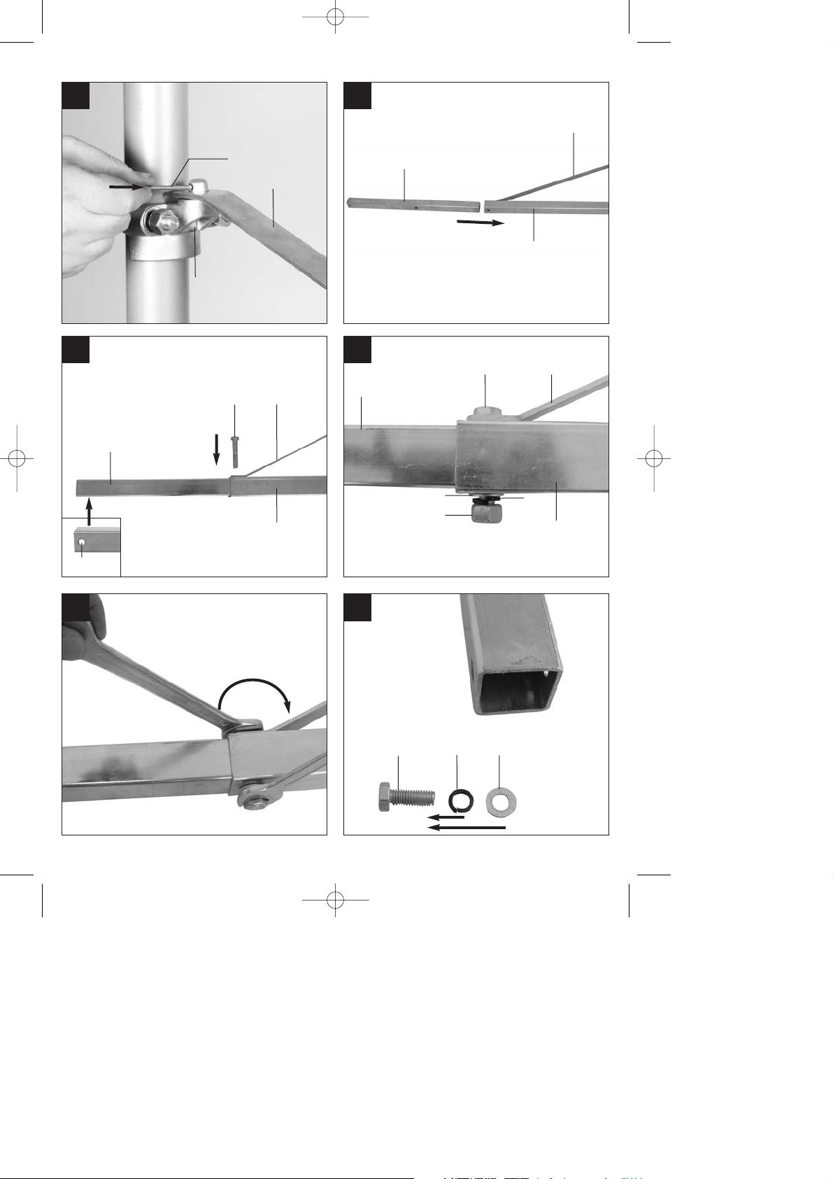
Apriete los tornillos del manguito de tubo.
El par de apriete de las tuercas (9) ha de
ser de 45 Nm.
Introduzca el tubo de extensión (6) con el
lado sin orificio en el brazo de extensión
cuadrado (5) (fig. 11). Asegúrese de que el
orificio (C) esté fuera, tal y como muestra la
figura 12.
Una el brazo de apoyo (4) con el brazo de
extensión cuadrado (5) y el perfil tubular
(6), introduciendo el tornillo hexagonal (17)
en las perforaciones superpuestas,
pasando además una arandela (20) y la
arandela elástica (19) a través del tornillo
(17) y apretándolo por medio de una tuerca
hexagonal (18) (fig. 12-14).
Coloque un tornillo en el extremo del tubo
de prolongación (16) a fin de evitar que
descienda el torno de cable (fig. 15-17).
La volada de 750 mm permite colocar un
peso de elevación inferior a 600 kg (fig.
18).
La volada de 1100 mm permite colocar un
peso de elevación inferior a 300 kg (fig.
Anleitung_LB5_2255413:_ 21.07.2011 10:32 Uhr Seite 9
Page 10

ES
10
20).
Al montar el torno en el perfil tubular (6), se
han de fijar las bases (12) bajo los estribos
de sujeción a fin de garantizar un apoyo
seguro del torno (fig. 19). Tras el montaje,
se ha de efectuar en primer lugar, un test
de marcha en vacío dos veces hacia arriba
y hacia abajo, así como un test de
oscilación de 180° hacia la izquierda y
hacia la derecha. A continuación, el torno
de cable se ha de cargar progresivamente
con un peso mayor hasta alcanzar el
máximo. Solo entonces se podrá poner en
funcionamiento normal el torno de cable.
8. Mantenimiento, limpieza y
pedido de piezas de repuesto
8.1 Limpieza y mantenimiento
Limpiar periódicamente el brazo oscilante y
lubricar los pasadores de bisagra (A/B).
8.2 Pedido de piezas de recambio:
Al solicitar recambios se indicarán los datos
siguientes:
Tipo de aparato
No. de artículo del aparato
No. de identidad del aparato
Encontrará los precios y la información actual
en www.isc-gmbh.info
9. Eliminación y reciclaje
El aparato está protegido por un embalaje para
evitar daños producidos por el transporte. Este
embalaje es materia prima y, por eso, se
puede volver a utilizar o llevar a un punto de
reciclaje. El aparato y sus accesorios están
compuestos de diversos materiales, como, p.
ej., metal y plástico. Depositar las piezas
defectuosas en un contenedor destinado a
residuos industriales. Informarse en el
organismo responsable al respecto en su
municipio o en establecimientos
especializados.
Anleitung_LB5_2255413:_ 21.07.2011 10:32 Uhr Seite 10
Page 11

ES
11
10. CERTIFICADO DE GARANTÍA
Estimado cliente:
Nuestros productos están sometidos a un estricto control de calidad. No obstante, lamentaríamos que este
aparato dejara de funcionar correctamente, en tal caso, le rogamos que se dirija a nuestro servicio de atención
al cliente en la dirección indicada en la parte inferior de la presente tarjeta de garantía. Con mucho gusto le
atenderemos también telefónicamente en el número de servicio indicado a continuación. Para hacer válido el
derecho de garantía, proceda de la siguiente forma:
1. Estas condiciones de garantía regulan prestaciones de la garantía adicionales. Sus derechos legales a
prestación de garantía no se ven afectados por la presente garantía. Nuestra prestación de garantía es
gratuita para usted.
2. La prestación de garantía se extiende exclusivamente a defectos ocasionados por fallos de material o de
producción y está limitada a la reparación de los mismos o al cambio del aparato. Tenga en consideración
que nuestro aparato no está indicado para un uso comercial, en taller o industrial. Por lo tanto, no
procederá un contrato de garantía cuando se utilice el aparato en zonas industriales, comerciales o talleres,
así como actividades similares. De nuestra garantía se excluye cualquier otro tipo de prestación adicional
por daños ocasionados por el transporte, daños ocasionados por la no observancia de las instrucciones de
montaje o por una instalación no profesional, no observancia de las instrucciones de uso (como, p. ej.,
conexión a una tensión de red o corriente no indicada), aplicaciones impropias o indebidas (como, p. ej.,
sobrecarga del aparato o uso de herramientas o accesorios no homologados), no observancia de las
disposiciones de mantenimiento y seguridad, introducción de cuerpos extraños en el aparato (como, p. ej.,
arena, piedras o polvo), uso violento o influencias externa (como, p. ej., daños por caídas), así como por el
desgaste habitual por el uso. Esto se aplica especialmente en aquellas baterías para las que ofrecemos un
plazo de garantía de 12 meses.
El derecho a garantía pierde su validez cuando ya se hayan realizado intervenciones en el aparato.
3. El periodo de garantía es de 3 años y comienza en la fecha de la compra del aparato. El derecho de
garantía debe hacerse válido, antes de finalizado el plazo de garantía, dentro de un periodo de dos
semanas una vez detectado el defecto. El derecho de garantía vence una vez transcurrido el plazo de
garantía. La reparación o cambio del aparato no conllevará ni una prolongación del plazo de garantía ni un
nuevo plazo de garantía ni para el aparato ni para las piezas de repuesto montadas. Esto también se aplica
en el caso de un servicio
in situ
.
4. Para hacer efectivo su derecho a garantía, envíe gratuitamente el aparato defectuoso a la dirección
indicada a continuación. Adjunte el original del ticket de compra u otro tipo de comprobante de compra con
fecha. ¡A tal efecto, guarde en lugar seguro el ticket de compra como comprobante! Describa con la mayor
precisión posible el motivo de la reclamación. Si nuestra prestación de garantía incluye el defecto
aparecido en el aparato, recibirá de inmediato un aparato reparado o nuevo de vuelta.
Naturalmente, también solucionaremos los defectos del aparato que no se encuentren comprendidos o ya no
se encuentren comprendidos en la garantía, en este caso contra reembolso de los costes. Para ello, envíe el
aparato a nuestra dirección de servicio técnico.
Comercial Einhell, S.A.
Travesia Villa Ester, 9 B
Poligono Industrial El Nogal
E-28119 Algete-Madrid
Tel. 0034 91 729 48 88
Anleitung_LB5_2255413:_ 21.07.2011 10:32 Uhr Seite 11
Page 12

IT/
MT
12
Indice Pagina
1. Introduzione..................................................................................13
2. Avvertenze di sicurezza................................................................13
3. Descrizione dell’apparecchio ed elementi forniti .........................13
4. Utilizzo proprio..............................................................................13
5. Caratteristiche tecniche................................................................14
6. Prima della messa in esercizio.....................................................14
7. Montaggio.....................................................................................14-15
8. Pulizia, manutenzione e ordinazione dei pezzi di ricambio ...........15
9. Smaltimento e riciclaggio..............................................................15
10. Certificato di garanzia ..................................................................16
La ristampa o l’ulteriore riproduzione, anche
parziale, della documentazione o dei
documenti d’accompagnamento dei prodotti è
consentita solo con l’esplicita autorizzazione
da parte della ISC GmbH.
Con riserva di apportare modifiche tecniche
Anleitung_LB5_2255413:_ 21.07.2011 10:32 Uhr Seite 12
Page 13

IT/
MT
13
1. Introduzione
Attenzione!
Nell’usare gli apparecchi si devono rispettare
diverse avvertenze di sicurezza per evitare
lesioni e danni. Quindi leggete attentamente
queste istruzioni per l’uso. Conservatele bene
per avere a disposizione le informazioni in
qualsiasi momento. Se date l’apparecchio ad
altre persone consegnate loro queste istruzioni
per l’uso insieme all’apparecchio!
Non ci assumiamo alcuna responsabilità per
incidenti o danni causati dal mancato rispetto
di queste istruzioni e delle avvertenze di
sicurezza.
2. Avvertenze di sicurezza
Osservate assolutamente i seguenti punti per
evitare infortuni e lesioni.
Non sottoponete il braccio orientabile a
sollecitazioni eccessive.
Non usatelo, se è danneggiato.
Fate attenzione che tutte le viti siano ben
avvitate e per la vostra propria sicurezza
controllatele regolarmente.
Fate attenzione che le copiglie siano fissate
correttamente nei fori.
È severamente vietato trasportare persone
con l’apparecchio di sollevamento a fune.
Inoltre è vietato sostare sotto l’apparecchio
di sollevamento a fune oppure sotto il
braccio orientabile.
Il prodotto non deve essere utilizzato da
persone che non conoscano queste misure
di sicurezza
Si deve controllare regolarmente che tutte le
parti non presentino eventuali deformazioni o
danni.
Rispettate il carico massimo permesso!
(vedi caratteristiche tecniche)
3. Descrizione dell’apparecchio
ed elementi forniti (Fig. 1/2)
1. Fascetta per tubo (con perno di cerniera A
grande)
2. 2 x Staffa per fascette per tubo
3. Fascetta per tubo (con perno di cerniera B
piccolo)
4. Braccio di sostegno
5. Braccio quadro 45 x 45 x 1,8 mm
6. Tubo di prolunga 40 x 40 x 2,5 mm
7. Copiglia Ø 3 x 45 mm
8. Copiglia Ø 3 x 60 mm
9. 4 x Dado a testa esagonale M10
10. 4 x Rosetta elastica Ø 10
11. 4 x Rosetta Ø 10
12. 2 x Spessore per morsetto
13. Dado a testa esagonale M8
14. Rosetta elastica Ø 8
15. Rosetta Ø 8
16. Vite a testa esagonale M8 x 15 mm
17. Vite a testa esagonale M 12 x 70 mm
18. Dado a testa esagonale M12
19. Rosetta elastica Ø 12
20. Rosetta Ø 12
4. Utilizzo proprio
Il braccio orientabile serve come sede di un
apparecchio di sollevamento a fune. A questo
scopo il braccio orientabile deve venire
montato ad una barra d’acciaio ben fissata del
diametro di 48 mm.
L’apparecchio deve venire usato solamente
per lo scopo a cui è destinato. Ogni altro tipo di
uso che esuli da quello previsto non è un uso
conforme. L’utilizzatore/l’operatore, e non il
costruttore, è responsabile dei danni e delle
lesioni di ogni tipo che ne risultino.
Tenete presente che i nostri apparecchi non
sono stati costruiti per l’impiego professionale,
artigianale o industriale. Non ci assumiamo
alcuna garanzia quando l’apparecchio viene
usato in imprese commerciali, artigianali o
industriali, o in attività equivalenti.
Anleitung_LB5_2255413:_ 21.07.2011 10:32 Uhr Seite 13
Page 14

5. Caratteristiche tecniche
Sbraccio I: carico max.:
l1= 750 mm m1= 600 kg
l2= 1100 mm m2= 300 kg
Area di rotazione: max. 180°
6. Prima della messa in esercizio
Il braccio orientabile serve ad alloggiare un
apparecchio di sollevamento a fune.
Per il fissaggio del braccio orientabile avete
bisogno di una barra d’acciaio tonda con un
diametro di Ø 48 mm, lo spessore della
parete non deve essere inferiore a 3 mm.
Fate attenzione che l’ancoraggio della
barra in acciaio resista alle forze che si
sviluppano. Rivolgetevi ad un ente
autorizzato per la consulenza. Questa
barra in acciaio non è compresa tra gli
elementi forniti.
7. Montaggio
Fissate la fascetta (1) (con perno di
cerniera grande (A)) ad una barra di
acciaio mediante la staffa per fascette (2),
le rosette (11), le rosette elastiche (10) e
due dadi a testa esagonale (9). Prima di
serrare le viti spostate le fascette (1)
all'altezza di lavoro desiderata del braccio
orientabile (Fig. 3-5).
Ingrassate il perno di cerniera (A) con
grasso lubrificante.
Agganciate quindi il braccio quadro (5) al
perno di cerniera (A) ed inserite la copiglia
(8) attraverso il foro nel perno di cerniera
(A) (Fig. 6-7).
Poi piegate le due estremità della copiglia
(8) divaricandole, in modo tale che la
copiglia (8) non possa uscire dal foro. (Fig.
8)
Ora fissate la fascetta (3) (con il perno
piccolo di cerniera (B)) alla barra di metallo
in modo analogo alla fascetta (1) al di
sopra del braccio quadro. Regolate quindi
l'altezza della fascetta superiore (3) in
modo tale che la distanza H fra le due
fascette (1/3) sia esattamente di 380 mm.
Agganciate ora il braccio di sostegno (4)
con il foro più grande al perno di cerniera
(B) della fascetta (3). Inserite la copiglia (7)
nel foro del perno di cerniera (B) e piegate
le due estremità della copiglia (7)
divaricandole, in modo che la copiglia (7)
non possa uscire dal foro (Fig. 9-10).
Serrate ora le viti delle fascette. Il momento
torcente per avvitare i dadi (9) deve essere
di 45 Nm.
Spingete il tubo di prolunga (6) con il lato
senza foro nel braccio quadro (5) (Fig. 11).
Fate attenzione che il foro (C) sia
all'esterno, come nella Fig. 12.
Collegate il braccio di sostegno (4) con il
braccio quadro (5) ed il tubo di prolunga (6)
inserendo la vite a testa esagonale (17)
attraverso i fori sovrapposti, spingendo una
rosetta (20) e la rosetta elastica (19) sopra
la vite (17) e serrandola con un dado a
testa esagonale (18) (Fig. 12-14).
Alla fine del tubo di prolunga viene montata
una vite (16) per evitare che il paranco
elettrico scivoli fuori. (Fig. 15-17).
Con lo sbraccio di 750 mm del paranco
elettrico non si deve sollevare un peso
superiore a 600 kg (Fig. 18).
Con lo sbraccio di 1100 mm del paranco
elettrico non si deve sollevare un peso
superiore a 300 kg (Fig. 20).
Montando il paranco elettrico al tubo di
prolunga (6) si devono fissare gli spessori
(12) sotto ai bloccaggi in modo da garantire
un arresto sicuro dello stesso (Fig. 19).
Dopo il montaggio si devono fare prima 2
prove a vuoto verso l'alto e verso il basso e
poi anche una prova di rotazione di 180°
verso destra e verso sinistra. Poi si devono
IT/
MT
14
Anleitung_LB5_2255413:_ 21.07.2011 10:32 Uhr Seite 14
Page 15

IT/
MT
15
eseguire prove con un peso sempre
maggiore fino a raggiungere il peso
massimo che possa venire sollevato con il
paranco elettrico. Solo dopo queste prove
si può iniziare il normale esercizio del
paranco elettrico.
8. Pulizia, manutenzione e
ordinazione dei pezzi di
ricambio
8.1 Pulizia e manutenzione
Pulite regolarmente il braccio orientabile e
lubrificate i perni di cerniera (A/B).
8.2 Ordinazione di pezzi di ricambio:
Volendo commissionare dei pezzi di ricambio,
si dovrebbe dichiarare quanto segue:
modello dell’apparecchio
numero dell’articolo dell’apparecchio
numero d’ident. dell’apparecchio
Per i prezzi e le informazioni attuali si veda
www.isc-gmbh.info
9. Smaltimento e riciclaggio
L’apparecchio si trova in una confezione per
evitare i danni dovuti al trasporto. Questo
imballaggio rappresenta una materia prima e
può perciò essere utilizzato di nuovo o
riciclato.
L’apparecchio e i suoi accessori sono fatti di
materiali diversi, per es. metallo e plastica.
Consegnate i pezzi difettosi allo smaltimento di
rifiuti speciali. Per informazioni rivolgetevi ad
un negozio specializzato o all’amministrazione
comunale!
Anleitung_LB5_2255413:_ 21.07.2011 10:32 Uhr Seite 15
Page 16

IT/
MT
16
10. CERTIFICATO DI GARANZIA
Gentili clienti,
i nostri prodotti sono soggetti ad un rigido controllo di qualità. Se l’apparecchio non dovesse tuttavia funzionare
correttamente, ci scusiamo e vi preghiamo di rivolgervi al nostro servizio di assistenza clienti all’indirizzo
indicato in questa scheda di garanzia. Siamo a vostra disposizione anche telefonicamente al numero del
servizio assistenza sotto indicato. Per la rivendicazione dei diritti di garanzia vale quanto segue:
1. Queste condizioni di garanzia regolano ulteriori prestazioni di garanzia. La presente garanzia non tocca i
vostri diritti al ricorso di garanzia previsti dalla legge. Le nostre prestazioni di garanzia sono per voi gratuite.
2. La prestazione di garanzia riguarda esclusivamente le anomalie riconducibili a difetti del materiale o di
produzione ed è limitata all’eliminazione di queste anomalie o alla sostituzione dell’apparecchio. Tenete
presente che i nostri apparecchi non sono stati costruiti per l’impiego professionale, artigianale o
industriale. Un contratto di garanzia non viene concluso quando l’apparecchio viene usato in imprese
commerciali, artigianali o industriali, o con attività equivalenti. Dalla nostra garanzia sono escluse inoltre le
prestazioni di risarcimento per danni dovuti al trasporto o danni causati dalla mancata osservanza delle
istruzioni per il montaggio o per installazione non corretta, dalla mancata osservanza delle istruzioni per
l’uso (come per es. collegamento a tensione di rete o tipo di corrente non corretto), dall’uso improprio o
illecito (come per es. sovraccarico dell’apparecchio o utilizzo di utensili o accessori non consentiti), dalla
mancata osservanza delle norme di sicurezza e di manutenzione, dalla penetrazione di corpi estranei
nell’apparecchio (come per es. sabbia, pietre o polvere), dall’impiego della forza o dall’influsso esterno
(come per es. danni dovuti a caduta) e dall’usura normale e dovuta all’impiego. Ciò vale particolarmente per
batterie, per esse concediamo tuttavia 12 mesi di garanzia
Il diritti di garanzia decadono quando sono già effettuati interventi sull’apparecchio.
3. Il periodo di garanzia è 3 anni e inizia alla data d’acquisto dell’apparecchio. I diritti di garanzia devono
essere fatti valere prima della scadenza del periodo di garanzia, entro due settimane dopo avere accertato
il difetto. È esclusa la rivendicazione di diritti di garanzia dopo la scadenza del relativo periodo. La
riparazione o la sostituzione dell’apparecchio non comporta una proroga del periodo di garanzia e con
questa prestazione per l’apparecchio o per pezzi di ricambio eventualmente installati non inizia un nuovo
periodo di garanzia. Questo vale anche nel caso si ricorra ad un servizio sul posto.
4. Per la rivendicazione dei vostri diritti di garanzia inviate l’apparecchio difettoso franco di porto all’indirizzo
sotto indicato. Allegate lo scontrino di cassa in originale o un’altra prova d’acquisto che riporti la data.
Conservate bene perciò lo scontrino di cassa come prova! Indicate il motivo di reclamo nel modo più
dettagliato possibile. Se il difetto dell’apparecchio rientra nella nostra prestazione di garanzia, ricevete
l’apparecchio riparato o un apparecchio nuovo a stretto giro di posta.
Naturalmente effettuiamo a pagamento anche riparazioni sull’apparecchio che non rientrano o non rientrano più
nella garanzia. A tale scopo inviate l’apparecchio all’indirizzo del servizio assistenza.
Einhell Italia s.r.l.
Via Marconi, 16
I-22070 Beregazzo (Co)
Tel. 031 992080 · Fax 031 992084
Anleitung_LB5_2255413:_ 21.07.2011 10:32 Uhr Seite 16
Page 17

GB/
MT
17
Table of contents: Page
1. Introduction .............................................................................18
2. Safety information...................................................................18
3. Layout and items supplied .....................................................18
4. Proper use ..............................................................................18
5. Technical data ........................................................................19
6. Before putting the machine into operation ..............................19
7. Mounting and assembly .........................................................19-20
8. Cleaning, maintenance and ordering of spare parts...............20
9. Disposal and recycling............................................................20
10. Guarantee Certificate .............................................................21
The reprinting or reproduction by any other
means, in whole or in part, of documentation
and papers accompanying products is
permitted only with the express consent of ISC
GmbH.
Technical changes subject to change
Anleitung_LB5_2255413:_ 21.07.2011 10:32 Uhr Seite 17
Page 18

GB/
MT
18
1. Introduction
Important!
When using equipment, a few safety
precautions must be observed to avoid injuries
and damage. Please read the complete
operating manual with due care. Keep this
manual in a safe place, so that the information
is available at all times. If you give the
equipment to any other person, give them
these operating instructions as well.
We accept no liability for damage or accidents
which arise due to non-observance of these
instructions and the safety information.
2. Safety information
Ensure that you observe the following points in
order to avoid accidents and injuries.
Do not overload your swing arm.
Do not continue to use the swing arm if it is
damaged.
Ensure that all bolts are tightly fastened
and check them frequently for your own
safety.
Ensure that the cotter pin is properly
inserted through the bore holes.
Lifting and carrying persons with the cable
winch is strictly prohibited! Additionally,
persons may not loiter underneath the
cable winch/swing arm assembly.
Persons who are not aware of these safety
precautions may not use this product.
All components must be regularly checked for
any kind of deformation or damage.
Observe the maximum permissible load
capacity (see „Technical Data“)!
3. Layout and items supplied
(Fig. 1/2)
1. Pipe collar (with large hinge pin A)
2. 2x holding bars for pipe collars
3. Pipe collar (with small hinge pin B)
4. Support arm
5. Square-edged boom 45 x 45 x 1.8 mm
6. Extension pipe 40 x 40 x 2.5 mm
7. Cotter pin Ø 3 x 45 mm
8. Cotter pin Ø 3 x 60 mm
9. 4x hexagon nuts M10
10. 4x spring washers Ø 10
11. 4x washers Ø 10
12. 2x pads for clamping brackets
13. Hexagon nut M8
14. Spring washer Ø 8
15. Washer Ø 8
16. Hexagon bolt M8 x 15 mm
17. Hexagon bolt M12 x 70 mm
18. Hexagon nut M12
19. Spring washer Ø 12
20. Washer Ø 12
4. Proper use
The swing arm is designed to be attached to a
cable winch. For this, the swing arm must be
mounted to a well fastened steel bar with a
diameter of 48 mm.
The machine is to be used only for its
prescribed purpose. Any other use is deemed
to be a case of misuse. The user / operator
and not the manufacturer will be liable for any
damage or injuries of any kind caused as a
result of this.
Please note that our equipment has not been
designed for use in commercial, trade or
industrial applications. Our warranty will be
voided if the machine is used in commercial,
trade or industrial businesses or for equivalent
purposes.
Anleitung_LB5_2255413:_ 21.07.2011 10:32 Uhr Seite 18
Page 19

GB/
MT
19
5. Technical data
Reach l: Max. load:
l1= 750 mm m1= 600 kg
l2= 1100 mm m2= 300 kg
Swing range: max. 180°
6. Before putting the machine
into operation
The swing arm is designed to take a cable
winch.
To mount the swing arm, you need a round
steel bar with a diameter of Ø 48 mm; its
wall must be a minimum of 3 mm thick.
Ensure that the anchor points of the steel
bar are able to adequately support the
forces that will be applied to it. Consult an
authorized professional to ensure that this
is properly done. This steel bar is not
included in the scope of delivery.
7. Mounting and assembly
Attach the pipe collar (1) (with the large
hinge pin (A)) to a steel bar using the
holding bar for the pipe collar (2), washers
(11), spring washers (10) and two hexagon
nuts (9). Before you tighten the bolts, push
the pipe collars (1) to the desired working
height of the swing arm (Figure 3-5).
Apply lubricating grease to the hinge pin
(A).
Slide the square-edged boom (5) over the
hinge pin (A) and push the cotter pin (8)
through the hole in the hinge pin (A) (Figure
6-7).
Finally, bend apart the two shanks of the
cotter pin (8) so that the cotter pin (8)
cannot work its way out of the bore hole.
(Figure 8)
Now attach the pipe collar (3) (with the
small hinge pin (B)) to the steel bar above
the square-edged boom in the same way
as you did with pipe collar (1). Adjust the
height of the upper pipe collar (3) so that
the distance H between the two pipe collars
(1/3) measures exactly 380 mm.
Slide the support arm (4) with the larger
bore hole over the hinge pin (B) of the pipe
collar (3). Push the cotter pin (7) into the
bore hole of the hinge pin (B) and bend
apart the two shanks of the cotter pin (7) so
that the cotter pin (7) cannot work its way
out of the bore hole (Figure 9-10).
Now tighten the bolts of the pipe collars.
Use a torque of 45 Nm to tighten the nuts
(9).
Push the extension pipe (6) by its end with
no bore hole into the square-edged boom
(5) (Figure 11). Make sure that the bore
hole (C) is on the outside as shown in
Figure 12.
Connect the support arm (4) to the square-
edged boom (5) and the extension pipe (6)
by inserting the hexagon bolt (17) through
the coinciding bore holes, placing a washer
(20) and a spring washer (19) over the bolt
(17), and securing the connection with a
hexagon nut (18) (Figure 12-14).
A bolt (16) is inserted at the end of the
extension pipe to prevent the cable winch
from sliding off (Figure 15-17).
When the cable winch is pushed out to 750
mm, it is not allowed to lift more than 600
kg (Figure 18).
When the cable winch is pushed out to
1100 mm, it is not allowed to lift more than
300 kg (Figure 20).
When mounting the cable winch on the
extension pipe (6), the pads (12) must be
pushed in under the clamping brackets in
order to ensure that the cable winch is held
securely in place (Figure 19). When the
assembly work is finished, an up and down
Anleitung_LB5_2255413:_ 21.07.2011 10:32 Uhr Seite 19
Page 20

GB/
MT
20
test and a 180° left and right swing test
must each be performed twice with no load.
Then the cable winch must be loaded with
increasingly heavier loads up to the
maximum permissible load weight. Only
when the cable winch has passed these
tests are you allowed to use the equipment
for normal operations.
8. Cleaning, maintenance and
ordering of spare parts
8.1 Cleaning and maintenance
Regularly clean the swing arm and lubricate
the hinge pins (A/B).
8.2 Ordering replacement parts:
Please quote the following data when ordering
replacement parts:
Type of machine
Article number of the machine
Identification number of the machine
For our latest prices and information please go
to www.isc-gmbh.info
9. Disposal and recycling
The unit is supplied in packaging to prevent its
being damaged in transit. This packaging is
raw material and can therefore be reused or
can be returned to the raw material system.
The unit and its accessories are made of
various types of material, such as metal and
plastic. Defective components must be
disposed of as special waste. Ask your dealer
or your local council.
Anleitung_LB5_2255413:_ 21.07.2011 10:32 Uhr Seite 20
Page 21

21
GB/
MT
10. GUARANTEE CERTIFICATE
Dear Customer,
All of our products undergo strict quality checks to ensure that they reach you in perfect condition. In the unlikely
event that your device develops a fault, please contact our service department at the address shown on this
guarantee card. Of course, if you would prefer to call us then we are also happy to offer our assistance under
the service number printed below. Please note the following terms under which guarantee claims can be made:
1. These guarantee terms cover additional guarantee rights and do not affect your statutory warranty rights.
We do not charge you for this guarantee.
2. Our guarantee only covers problems caused by material or manufacturing defects, and it is restricted to the
rectification of these defects or replacement of the device. Please note that our devices have not been
designed for use in commercial, trade or industrial applications. Consequently, the guarantee is invalidated
if the equipment is used in commercial, trade or industrial applications or for other equivalent activities. The
following are also excluded from our guarantee: compensation for transport damage, damage caused by
failure to comply with the installation/assembly instructions or damage caused by unprofessional
installation, failure to comply with the operating instructions (e.g. connection to the wrong mains voltage or
current type), misuse or inappropriate use (such as overloading of the device or use of non-approved tools
or accessories), failure to comply with the maintenance and safety regulations, ingress of foreign bodies
into the device (e.g. sand, stones or dust), effects of force or external influences (e.g. damage caused by
the device being dropped) and normal wear resulting from proper operation of the device.
This applies in
particular to rechargeable batteries for which we nevertheless issue a guarantee period of 12 months.
The guarantee is rendered null and void if any attempt is made to tamper with the device.
3. The guarantee is valid for a period of 3 years starting from the purchase date of the device. Guarantee
claims should be submitted before the end of the guarantee period within two weeks of the defect being
noticed. No guarantee claims will be accepted after the end of the guarantee period. The original guarantee
period remains applicable to the device even if repairs are carried out or parts are replaced. In such cases,
the work performed or parts fitted will not result in an extension of the guarantee period, and no new
guarantee will become active for the work performed or parts fitted. This also applies when an on-site
service is used.
4. In order to assert your guarantee claim, please send your defective device postage-free to the address
shown below. Please enclose either the original or a copy of your sales receipt or another dated proof of
purchase. Please keep your sales receipt in a safe place, as it is your proof of purchase. It would help us if
you could describe the nature of the problem in as much detail as possible. If the defect is covered by our
guarantee then your device will either be repaired immediately and returned to you, or we will send you a
new device.
Of course, we are also happy offer a chargeable repair service for any defects which are not covered by the
scope of this guarantee or for units which are no longer covered. To take advantage of this service, please send
the device to our service address.
Einhell Italia s.r.l.
Via Marconi, 16
I-22070 Beregazzo (Co)
Tel. 031 992080 · Fax 031 992084
Anleitung_LB5_2255413:_ 21.07.2011 10:32 Uhr Seite 21
Page 22

DE/AT/
CH
22
Inhaltsverzeichnis Seite
1. Einleitung ................................................................................23
2. Sicherheitshinweise ................................................................23
3. Gerätebeschreibung und Lieferumfang ..................................23
4. Bestimmungsgemäße Verwendung........................................23-24
5. Technische Daten...................................................................24
6. Vor Inbetriebnahme ................................................................24
7. Montage..................................................................................24-25
8. Reinigung, Wartung und Ersatzteilbestellung.........................25
9. Entsorgung und Wiederverwertung .......................................25
10. Garantieurkunde .....................................................................26
Der Nachdruck oder sonstige Vervielfältigung
von Dokumentation und Begleitpapieren der
Produkte, auch auszugsweise ist nur mit ausdrücklicher Zustimmung der ISC GmbH
zulässig.
Technische Änderungen vorbehalten
Anleitung_LB5_2255413:_ 21.07.2011 10:32 Uhr Seite 22
Page 23

1. Einleitung
Achtung!
Beim Benutzen von Geräten müssen einige
Sicherheitsvorkehrungen eingehalten werden,
um Verletzungen und Schäden zu verhindern.
Lesen Sie diese Bedienungsanleitung /
Sicherheitshinweise deshalb sorgfältig durch.
Bewahren Sie diese gut auf, damit Ihnen die
Informationen jederzeit zur Verfügung stehen.
Falls Sie das Gerät an andere Personen
übergeben sollten, händigen Sie diese
Bedienungsanleitung / Sicherheitshinweise
bitte mit aus. Wir übernehmen keine Haftung
für Unfälle oder Schäden, die durch
Nichtbeachten dieser Anleitung und den
Sicherheitshinweisen entstehen.
2. Sicherheitshinweise
Beachten Sie unbedingt folgende Punkte, um
Unfälle und Verletzungen zu vermeiden.
Überlasten Sie den Schwenkarm nicht.
Bei Beschädigung den Schwenkarm nicht
weiter Benutzen.
Achten Sie darauf, dass alle Schrauben
fest angezogen sind. Kontrollieren Sie zu
Ihrer eigenen Sicherheit diese regelmäßig
nach.
Achten Sie darauf, dass die Splinte
ordnungsgemäß in den Bohrungen
befestigt sind.
Es ist streng verboten, Personen mit dem
Seilhebezug zu befördern. Des Weiteren
dürfen sich keine Personen unter dem
Seilhebezug bzw. Schwenkarm aufhalten.
Es darf keine Person, die diese
Sicherheitskenntnisse nicht kennt, dieses
Produkt verwenden.
Alle Teile müssen regelmäßig auf
irgendwelche Verformung oder Schädigung
geprüft werden.
Beachten Sie die maximal zulässige
Belastung! (siehe techn. Daten)
3. Gerätebeschreibung und
Lieferumfang (Bild 1/2)
1. Rohrmanschette
(mit großem Scharnierstift A)
2. 2x Haltebügel für Rohrmanschetten
3. Rohrmanschette
(mit kleinem Scharnierstift B)
4. Stützarm
5. Vierkantausleger 45 x 45 x 1,8 mm
6. Verlängerungsrohr 40 x 40 x 2,5 mm
7. Splint Ø 3 x 45 mm
8. Splint Ø 3 x 60 mm
9. 4 x Sechskantmutter M10
10. 4 x Federscheibe Ø 10
11. 4 x U-Scheibe Ø 10
12. 2 x Unterlage für Klemmbügel
13. Sechskantmutter M8
14. Federscheibe Ø 8
15. U-Scheibe Ø 8
16. Sechskantschraube M8 x 15 mm
17. Sechskantschraube M 12 x 70 mm
18. Sechskantmutter M12
19. Federscheibe Ø 12
20. U-Scheibe Ø 12
4. Bestimmungsgemäße
Verwendung
Der Schwenkarm dient zur Aufnahme eines
Seilhebezuges. Hierbei muss der Schwenkarm
an einer gut befestigten Stahlstange mit einem
Durchmesser von 48 mm montiert werden.
Die Maschine darf nur nach ihrer Bestimmung
verwendet werden. Jede weitere darüber
hinausgehende Verwendung ist nicht
bestimmungsgemäß. Für daraus
hervorgerufene Schäden oder Verletzungen
aller Art haftet der Benutzer/Bediener und nicht
der Hersteller.
Bitte beachten Sie, dass unsere Geräte
bestimmungsgemäß nicht für den
gewerblichen, handwerklichen oder
industriellen Einsatz konstruiert wurden. Wir
übernehmen keine Gewährleistung, wenn das
DE/AT/
CH
23
Anleitung_LB5_2255413:_ 21.07.2011 10:32 Uhr Seite 23
Page 24

Gerät in Gewerbe-, Handwerks- oder
Industriebetrieben sowie bei
gleichzusetzenden Tätigkeiten eingesetzt wird.
5. Technische Daten
Ausladung: max. Last:
l1= 750 mm m1= 600 kg
l2= 1100 mm m2= 300 kg
Schwenkbereich: max. 180°
6. Vor Inbetriebnahme
Der Schwenkarm dient als Aufnahme für
einen Seilhebezug.
Zur Befestigung des Schwenkarms
benötigen Sie eine runde Stahlstange mit
einem Durchmesser von Ø 48 mm, die
Wandstärke darf nicht kleiner als 3 mm
sein. Achten Sie darauf, dass die
Verankerung der Stahlstange die
auftretenden Kräfte aushält. Lassen Sie
sich von einer autorisierten Fachstelle
beraten. Diese Stahlstange ist nicht im
Lieferumfang enthalten.
7. Montage
Befestigen Sie die Rohrmanschette (1) (mit
großem Scharnierstift (A)) mittels dem
Haltebügel für die Rohrmanschette (2),
Unterlegscheiben (11), Federscheiben (10)
und zweier Sechskantmuttern (9) an einer
Stahlstange. Bevor Sie die Schrauben
festziehen, schieben Sie die
Rohrmanschetten (1) auf die gewünschte
Arbeitshöhe des Schwenkarms (Bild 3-5).
Fetten Sie den Scharnierstift (A) mit
Schmierfett ein.
Hängen Sie dann den Vierkantausleger (5)
an den Scharnierstift (A) und schieben Sie
den Splint (8) durch das Loch im
Scharnierstift (A) (Bild 6-7).
Anschließend biegen Sie die beiden
Schenkel des Splintes (8) auseinander, so
dass der Splint (8) nicht aus der Bohrung
herausrutschen kann. (Bild 8)
Nun befestigen Sie die Rohrmanschette (3)
(mit kleinem Scharnierstift(B)) analog wie
die Rohrmanschette (1) oberhalb des
Vierkantauslegers an der Stahlstange.
Richten Sie dabei die Höhe der oberen
Rohrmanschette (3) so aus, dass der
Abstand H zwischen den beiden
Rohrmanschetten (1/3) genau 380 mm
beträgt.
Hängen Sie nun den Stützarm (4) mit der
größeren Bohrung am Scharnierstift (B) der
Rohrmanschette (3) ein. Schieben Sie den
Splint (7) in die Bohrung des
Scharnierstiftes (B) und biegen Sie die
beiden Schenkels des Splintes (7)
auseinander, so dass der Splint (7) nicht
aus der Bohrung herausrutschen kann (Bild
9-10).
Ziehen Sie jetzt die Schrauben der
Rohrmanschetten fest. Das
Verschraubungsdrehmoment der Muttern
(9) muss 45 Nm. betragen.
Schieben Sie das Verlängerungsrohr (6)
mit der Seite ohne Bohrung in den
Vierkantausleger (5) (Bild 11). Achten Sie
darauf, dass die Bohrung (C), wie in
Abbildung 12 zu sehen, außen ist.
Verbinden Sie den Stützarm (4) mit dem
Vierkantausleger (5) und dem Verlängerungsrohr (6), indem Sie die
Sechskantschraube (17) durch die
übereinanderliegenden Bohrungen
stecken, eine Unterlegscheibe (20) und die
Federscheibe (19) über die Schraube (17)
schieben und mit einer Sechskantmutter
(18) festziehen (Bild 12-14).
Am Ende des Verlängerungsrohres wird
eine Schraube (16) montiert, um das
Heruntergleiten des Seilhebezugs zu
DE/AT/
CH
24
Anleitung_LB5_2255413:_ 21.07.2011 10:32 Uhr Seite 24
Page 25

verhindern. (Bild 15-17).
Mit der Ausladung 750 mm des
Seilhebezuges darf das Hebegewicht nicht
größer als 600 kg werden (Bild 18).
Mit der Ausladung 1100 mm des
Seilhebezuges darf das Hebegewicht nicht
größer als 300 kg werden (Bild 20).
Bei der Montage des Seilhebezuges am
Verlängerungsrohr (6) müssen unter den
Klemmbügeln die Unterlagen (12) befestigt
werden, um einen sicheren Halt des
Seilhebezuges zu gewährleisten (Bild 19).
Nach der Montage muss zuerst ein
2-maliger Leerlauftest nach oben und unten
sowie 180° Schwenktest nach links und
nach rechts gemacht werden. Dann muss
mit immer größerem Hebegewicht bis zum
größten Hebegewicht der Seilhebezug
belastet werden. Erst danach kann der
Seilhebezug im normalen Betrieb
genommen werden.
8. Reinigung, Wartung und
Ersatzteilbestellung
8.1 Reinigung und Wartung
Reinigen Sie den Schwenkarm regelmäßig und
schmieren Sie die Scharnierstifte (A/B).
8.2 Ersatzteilbestellung:
Bei der Ersatzteilbestellung müssen folgende
Angaben gemacht werden:
Typ des Gerätes
Artikelnummer des Gerätes
Ident-Nummer des Gerätes
Aktuelle Preise und Infos finden Sie unter
www.isc-gmbh.info
9. Entsorgung und
Wiederverwertung
Das Gerät befindet sich in einer Verpackung
um Transportschäden zu verhindern. Diese
Verpackung ist Rohstoff und ist somit wieder
verwendbar oder kann dem Rohstoffkreislauf
zurückgeführt werden. Das Gerät und dessen
Zubehör bestehen aus verschiedenen
Materialien, wie z.B. Metall und Kunststoffe.
Führen Sie defekte Bauteile der
Sondermüllentsorgung zu. Fragen Sie im
Fachgeschäft oder in der Gemeindeverwaltung
nach!
DE/AT/
CH
25
Anleitung_LB5_2255413:_ 21.07.2011 10:32 Uhr Seite 25
Page 26

DE/AT/
CH
26
10. GARANTIEURKUNDE
Sehr geehrte Kundin, sehr geehrter Kunde,
unsere Produkte unterliegen einer strengen Qualitätskontrolle. Sollte dieses Gerät dennoch einmal nicht einwandfrei funktionieren, bedauern wir dies sehr und bitten Sie, sich an unseren Servicedienst unter der auf dieser Garantiekarte angegebenen Adresse zu wenden. Gern stehen wir Ihnen auch telefonisch über die unten
angegebene Servicerufnummer zur Verfügung. Für die Geltendmachung von Garantieansprüchen gilt Folgendes:
1. Diese Garantiebedingungen regeln zusätzliche Garantieleistungen. Ihre gesetzlichen Gewährleistungsansprüche werden von dieser Garantie nicht berührt. Unsere Garantieleistung ist für Sie kostenlos.
2. Die Garantieleistung erstreckt sich ausschließlich auf Mängel, die auf Material- oder Herstellungsfehler zurückzuführen sind und ist auf die Behebung dieser Mängel bzw. den Austausch des Gerätes beschränkt.
Bitte beachten Sie, dass unsere Geräte bestimmungsgemäß nicht für den gewerblichen, handwerklichen
oder industriellen Einsatz konstruiert wurden. Ein Garantievertrag kommt daher nicht zustande, wenn das
Gerät in Gewerbe-, Handwerks- oder Industriebetrieben sowie bei gleichzusetzenden Tätigkeiten eingesetzt wird.
Von unserer Garantie sind ferner Ersatzleistungen für Transportschäden, Schäden durch Nichtbeachtung
der Montageanleitung oder aufgrund nicht fachgerechter Installation, Nichtbeachtung der Gebrauchsanleitung (wie durch z.B. Anschluss an eine falsche Netzspannung oder Stromart), missbräuchliche oder unsachgemäße Anwendungen (wie z.B. Überlastung des Gerätes oder Verwendung von nicht zugelassenen
Einsatzwerkzeugen oder Zubehör), Nichtbeachtung der Wartungs- und Sicherheitsbestimmungen, Eindringen von Fremdkörpern in das Gerät (wie z.B. Sand, Steine oder Staub), Gewaltanwendung oder
Fremdeinwirkungen (wie z. B. Schäden durch Herunterfallen) sowie durch verwendungsgemäßen, üblichen
Verschleiß ausgeschlossen. Dies gilt insbesondere für Akkus, auf die wir dennoch eine Garantiezeit von
12 Monaten gewähren
Der Garantieanspruch erlischt, wenn an dem Gerät bereits Eingriffe vorgenommen wurden.
3. Die Garantiezeit beträgt 3 Jahre und beginnt mit dem Kaufdatum des Gerätes. Garantieansprüche sind vor
Ablauf der Garantiezeit innerhalb von zwei Wochen, nachdem Sie den Defekt erkannt haben, geltend zu
machen. Die Geltendmachung von Garantieansprüchen nach Ablauf der Garantiezeit ist ausgeschlossen.
Die Reparatur oder der Austausch des Gerätes führt weder zu einer Verlängerung der Garantiezeit noch
wird eine neue Garantiezeit durch diese Leistung für das Gerät oder für etwaige eingebaute Ersatzteile in
Gang gesetzt. Dies gilt auch bei Einsatz eines Vor-Ort-Services.
4. Für die Geltendmachung Ihres Garantieanspruches übersenden Sie bitte das defekte Gerät portofrei an die
unten angegebene Adresse. Fügen Sie den Verkaufsbeleg im Original oder einen sonstigen datierten Kaufnachweis bei. Bitte bewahren Sie deshalb den Kassenbon als Nachweis gut auf! Beschreiben Sie uns bitte
den Reklamationsgrund möglichst genau. Ist der Defekt des Gerätes von unserer Garantieleistung erfasst,
erhalten Sie umgehend ein repariertes oder neues Gerät zurück.
Selbstverständlich beheben wir gegen Erstattung der Kosten auch gerne Defekte am Gerät, die vom Garantieumfang nicht oder nicht mehr erfasst sind. Dazu senden Sie das Gerät bitte an unsere Serviceadresse.
Einhell Italia s.r.l.
Via Marconi, 16
I-22070 Beregazzo (Co)
Tel. 031 992080 · Fax 031 992084
Anleitung_LB5_2255413:_ 21.07.2011 10:32 Uhr Seite 26
Page 27

27
Anleitung_LB5_2255413:_ 21.07.2011 10:32 Uhr Seite 27
Page 28

IAN: 66764 PSZ 250 A2
Einhell Germany AG
Wiesenweg 22
D-94405 Landau/Isar
Estado de las informaciones · Versione delle informazioni
Last Information Update · Stand der Informationen:
05/2011 Ident.-No.: 22.554.13 052011 - 5
5
BRAZO GIRATORIO PARA
POLIPASTO DE CABLE
Anleitung_LB5_2255413:_ 21.07.2011 10:32 Uhr Seite 28
 Loading...