


Paradigm OM-575, MILLENIA FRONT AND CENTER SPEAKERS User Manual

OWNERS MANUAL OM-575
Paradigm Electronics Inc. In Canada: 205 Annagem Blvd., Mississauga, ON L5T 2V1 • In the U.S.: MPO Box 2410, Niagara Falls, NY 14302
MILLENIA™SERIES:
FRONT AND CENTER SPEAKERS
Thank you for choosing Paradigm®Reference Millenia™Speakers and
congratulations! You are about to hear the difference these state-of-the-art
high-end speakers will make in your music and home theater system.
Comprehensive R&D, leading-edge design, use of the finest materials, and
sophisticated manufacturing and quality control techniques provide vastly
superior performance for each component part and at every stage of design.
Your Paradigm®Reference Millenia™speakers will provide you with stunning
high-end sound and unparalleled listening pleasure for many years.
To achieve all of the exceptional sound these speakers are capable of providing
requires care in installation and operation. Please take the time to read this
manual and follow all instructions. If you have further questions, contact your
Authorized Paradigm®Reference Dealer or visit the Q&A page in the Tech
Support section of our website at www.paradigm.com.

2
Base Assembly for Floorstanding Speakers
(Pictorial) . . . . . . . . . . . . . . . . . . . . . . . . . . . . . . . . . . . 3
Grille Removal and Reinstallation (Pictorial) . . . . 3
Speaker Placement and Connection (Pictorial) . . 4
Your New Speakers . . . . . . . . . . . . . . . . . . . . . . . 7
How To Avoid Speaker Damage . . . . . . . . . . . . 8
Room Acoustics . . . . . . . . . . . . . . . . . . . . . . . . . 8
Speaker Placement . . . . . . . . . . . . . . . . . . . . . . . 9
Wall Mounting . . . . . . . . . . . . . . . . . . . . . . . . . . 10
Speaker Connection . . . . . . . . . . . . . . . . . . . . . 10
Fine Tuning . . . . . . . . . . . . . . . . . . . . . . . . . . . . 10
Troubleshooting Guide . . . . . . . . . . . . . . . . . . . 11
Limited Warranty . . . . . . . . . . . . . . . . . . . . . . . 11
TABLE OF CONTENTS
RECYCLING AND REUSE GUIDELINES FOR EUROPE
In accordance with the European Union WEEE (Waste Electrical and Electronic Equipment) directive effective August
13, 2005, we would like to notify you that this product may contain regulated materials which, upon disposal, according
to the WEEE directive, require special reuse and recycling processing. For this reason Paradigm Electronics Inc.
(manufacturers of Paradigm
®
speakers and Anthem®electronics) has arranged with our distributors in European
Union member nations to collect and recycle this product at no cost to you. To find your local distributor please contact
the dealer from whom you purchased this product or go to our website at www.paradigm.com.
Please note that the product only falls under the WEEE directive. When disposing of packaging and other shipping
material we encourage you to recycle through the normal channels.
DIRECTIVES EUROPEENNES SUR LE RECYCLAGE ET LE TRAITEMENT DES DECHETS
Dans le respect de la directive WEEE (Waste Electrical & Electronic Equipment) mise en place par les institutions Européennes
à compter du 13 Août 2005, nous souhaitons vous informer que ce produit peut contenir des matières devant faire l’objet
d’une procédure de recyclage ou de traitement approprié des déchets. Dans cette optique, Paradigm Electronics Inc
(fabricant des enceintes Paradigm
MD
et des électroniques AnthemMD) avec ses Distributeurs agréés dans l’Union
Européenne, ont mis en place une procédure de collecte et de retraitement gratuite. Pour en savoir davantage sur cette
procédure veuillez contacter votre revendeur, ou notre Distributeur dans votre pays (vous en obtiendrez les coordonnées
sur simple demande ou en consultant notre site Internet www.paradigm.com).
Notez que seul le produit fini est concerné par cette directive et ses obligations. S’agissant de son emballage et de
ses accessoires de transport nous vous recommandons de les recycler selon les procédures mises en place par
votre commune ou votre département.
3
x4
x4
OR
OU
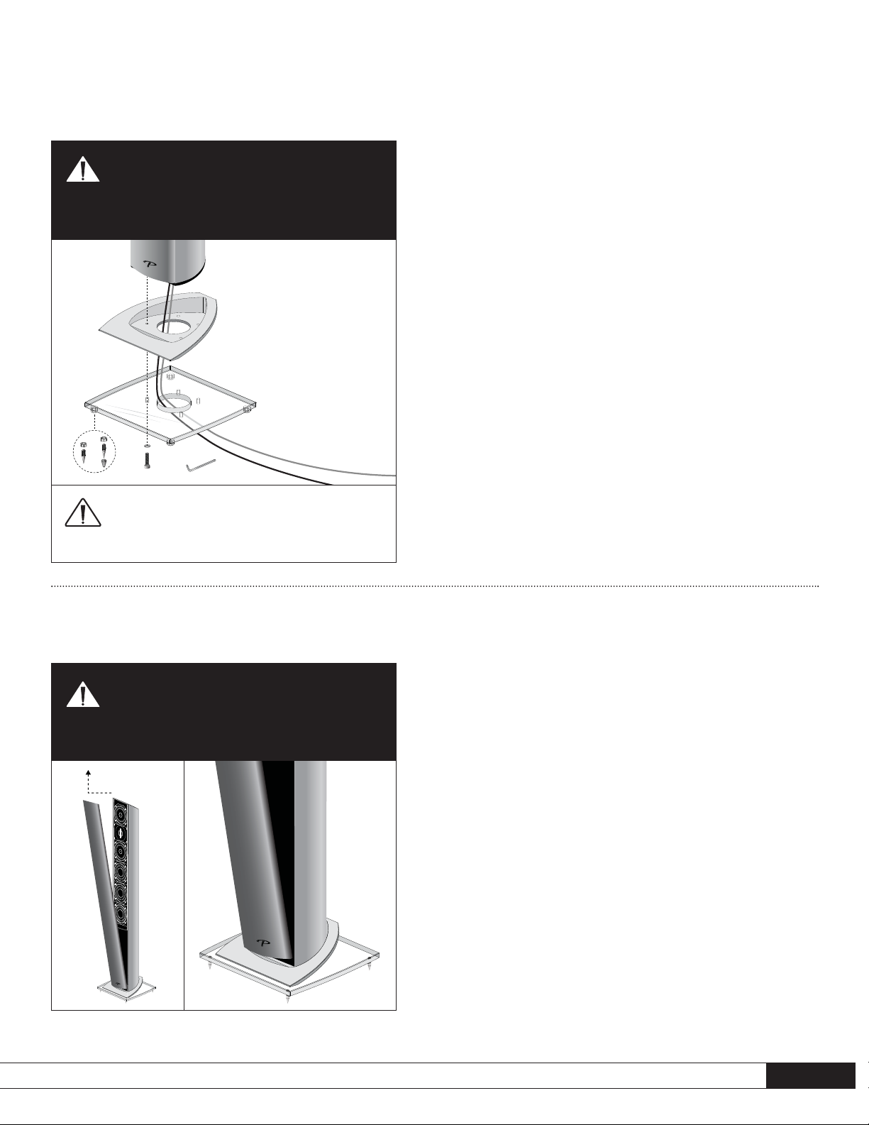
BASE ASSEMBLY FOR FLOORSTANDING SPEAKERS
(pictorial)
ASSEMBLAGE DE LA BASE DES ENCEINTES AU SOL
(figures)
Fig. 1
Fig. 2
GRILLE REMOVAL AND REINSTALLATION
(pictorial)
RETRAIT ET RÉINSTALLATION DE LA GRILLE
(figures)
DO NOT overtighten screws when attaching glass
base to speaker
NE PAS trop serrer les vis au moment de fixer la
base en verre à l’enceinte
IMPORTANT:
Lay speaker on its side to
assemble base.
Coucher l’enceinte sur le
côté avant d’assembler
la base.
Turn amplifier OFF before connecting
ÉNTEINDRE l’amplificateur avant de procéder au
raccordement
To make connection easier, we recommend feeding cable through base/bottom
plate and connecting speaker before attaching base.
Pour faciliter le raccordement, il est recommandé de faire passer le fil de l’enceinte
à travers la base/plaque inférieure avant de fixer la base.
TO AVOID scratching base, remove and reinstall
grille as shown
POUR ÉVITER d’égratigner la base, retirer et
réinstaller la grille tel qu’illustré

4
SPEAKER PLACEMENT AND CONNECTION
(pictorial)
POSITIONNEMENT ET RACCORDEMENT
(figures)
Fig. 3 Fig. 4a Fig. 4b
Fig. 5
up to / à
Fig. 6
Fig. 7 Fig. 8
Attaching the TV-Top/Shelf Supports
Fixation des supports pour télé/étagère
up to / à

5
Fig. 9a
NOTE: This step is for positioning only.
Screws will be removed in next step to
allow installation of additional bolts.
Position bracket and ensure it is level.
Mark the two inner
screw holes. Drill pilot
holes, then press anchor bolts firmly into
drywall and screw in. Follow with flathead
screws: DO NOT SCREW ALL THE WAY
IN AT THIS POINT —leave screw heads
protruding slightly.
IMPORTANT: Please read before installing brackets
Paradigm DOES NOT supply hardware for mounting brackets to the wall. Mounting hardware shown
is an example only; hardware will vary depending on wall type.
Install into 1/2˝ (13 mm) or 5/8˝ (16 mm) drywall only. Screws must be long enough to go through anchor
bolts and firmly into drywall
(see inset circle, below)
.
BRACKET INSTALLATION FOR MILLENIA™20 AND MILLENIA™30 (Figs. 9a – 9e)
BRACKET PARTS LIST
(per speaker)
:
• 1 – Wall-mounting bracket (with 2 protruding screw heads) • 2 – Sets of 2 self-adhesive bumper pads (marked for 0° or 7° tilt)
PARTS REQUIRED, NOT INCLUDED
(per speaker)
:
• 4 – Anchor bolts (minimum load rate 25 lb / 11.3 kg) • 4 – Flathead (Countersunk) screws
Fig. 9b
Bracket is slotted
(see illustration)
, to
allow further adjustment left or right, if
necessary. Re-check to ensure bracket is
level. Mark outer
screw holes.
Fig. 9c
Remove the two flathead screws
(not shown)
. Drill outer pilot holes, then press
anchor bolts firmly into drywall and screw in. Now insert all four flathead
screws and tighten.
WARNING! For stability, all four
flathead screws MUST be used.
WARNING! All screws must be inserted
straight and fully tightened to ensure
correct operation of anchor bolts.

Fig. 9d (Before wiring speakers see note on Fig. 9d – 1 and Fig. 9d – 2 below)
CONNECTING SPEAKER
Pull cables through center hole in bracket and connect speaker following the
information on Page 10.
ADJUSTING THE SPEAKER’S ANGLE OF TILT
The self-adhesive bumper pads
(included)
allow you to adjust the angle at which
your speakers sits on the wall:
• To further optimize imaging, you can tilt Left and Right speakers inward 7°
(Fig. 9d – 1) positioning the self-adhesive bumper pads marked 7°
(as shown)
.
• To further optimize clarity and intelligibility, you can tilt the center speaker up
7° or down 7° (Fig. 9d – 2) positioning the bumper pads marked 7°
(as shown)
.
• You can also mount the speakers parallel to the wall (Fig. 9d – 3) positioning
the self-adhesive bumper pads marked 0°
(as shown)
.
Adjustments should be done before mounting speakers to the wall:
6
Horizontal Position
LEFT SPEAKER RIGHT SPEAKER
Rotate speaker
before wiring!
Adjusting Tilt on Left / Right Speakers
Fig. 9d – 3
To mount all speakers parallel to wall, attach pads
marked 0°
(as shown)
.
ALL SPEAKERS
Mounting Speakers Parallel to Wall
Fig. 9d – 1
The above image shows top view looking toward
listening area. Pads must sit at edges closest to
on-wall display.
LEFT SPEAKER: To tilt speaker inward
, rotate
speaker 180° then attach the pads marked 7°
(as shown)
.
RIGHT SPEAKER: To tilt speaker inward
, simply
attach the pads marked 7°
(as shown)
.
CENTER SPEAKER
Tilted down
Tilted up.
Rotate speaker
before
wiring!
Adjusting Tilt on Center Speaker
Fig. 9d – 2
CENTER SPEAKER: (shown in side view) To tilt
speaker down
, attach pads marked 7°
(as shown)
.
To tilt speaker up, rotate speaker 180° then attach
pads marked 7°
(as shown)
.
POSITIONING BUMPER PADS
Perspective in images shows only one pad. Two
pads are required, positioned as shown on the
lower recessed areas
(shaded areas)
of the keyhole
slot sections
(see Inset below)
.
Fig. 9e
Align keyhole slots
(shown at right)
on rear of speaker with protruding screw heads on bracket, then using an “in-and-down”
motion mount speaker on bracket.
Horizontal Position
keyhole slots
 Loading...