

Page 1

MAF 900- 60S
MULTI- CARRIER
POWER
AMPLIFIER
USER MANUAL
Page 2

Table Of Contents
Page
Section 1 No.
General Description......................................................................................1
Section 2
Specifications................................................................................................2
Mechanical Specifications ............................................................................3
Environmental Specifications .......................................................................4
Section 3
Multi-Carrier Power Amplifier Principals of Operation...............................5
Principals of Operation.................................................................................6
Principals of Operation.................................................................................7
Section 4
Operating Instructions...................................................................................8
Section 5
Installation Instructions.................................................................................9
Installation Instructions................................................................................10
Installation Instructions................................................................................11
Section 6
Maintenance.................................................................................................12
Maintenance.................................................................................................13
Maintenance.................................................................................................14
Maintenance.................................................................................................15
Maintenance.................................................................................................16
Section 7
Troubleshooting ...........................................................................................17
Page 3

1
Section 1 Amplifier System Description
Introduction
This manual contains information and specifications of Paradigm Wireless Systems MAF
900-60S Multi-Carrier Power Amplifier. The purpose of this manual is to familiarize the
user to the basic operation and specification of the product. Any misuse of information
may lead to partial or total damage to the amplifier. This manual is organized into the
following sections:
Section 1 Amplifier System Description Section 6 Maintenance
Section 2 Amplifier Specifications Section 7 Troubleshooting
Section 3 Principals of Operation
Section 4 Operating Instructions
Section 5 Installations
1.1 General Description
The Paradigm Wireless Systems MAF 900-60S Multi-Carrier Power Amplifier (MCPA)
is designed to operate in the 5 MHz frequency band of 935 MHz to 940 MHz. The MAF
900-60S amplifiers are designed for 2-way paging radio transceiver base stations using
GMSK modulation. The MCPA is designed to integrate with a sub-rack system. Total
composite output power is 80 Watts from the MCPA.
The MCPA draws +27 Vdc power from the sub-rack. The LED on the front panel of the
MCPA will be GREEN during normal operation. Any alarm condition will turn the LED
to RED or AMBER. This will indicate an alarm condition within the MCPA. External
alarms for connecting to the base station will be sent via the D-subminiature connector
through the sub-rack. These are dry contact or RS485.
Fans are used to cool the heat sink to ensure unit performs to specification over the
temperature range. Air is pulled from the front of the amplifier and exhausted through the
back of the sub-rack. Over temperature alarms will shut down the MCPA when the heat
sink temperature reaches 95°C. The amplifier will auto restart when heat sink
temperature decreases to 75°C. This will prevent thermal run away of the MCPA.
Each MAF 900-60S MCPA will generate 1900 BTU of heat at full power. Proper cooling
and ventilation is essential for continuous operation of the amplifier.
Page 4

2
Section 2 MAF 900-60S Amplifier Specification
The MAF 900-60S MCPA series electrical specification:
Frequency Range 935-940 MHz
Channel Spacing 25 kHz
Input Power +5 dBm
Output Power 80 Watts (49.00 dBm)
Gain +58 dB
Gain Flatness
Normal Operating Voltage +27 Vdc
Current Consumption 27.5 Amps @ 80 Watts Power Output
Abnormal Operating
Voltage
Efficiency 10.77 %
RF Gain Variation over
Temperature
Gain Variation over
Dynamic Range
IMD -65 dBc min @ 25 kHz channel spacing, 75 Watts
Modulation Type GMSK
Output Return Loss -14 dB minimum
Output Protection Mismatched Protected
Output Isolation 20 dB minimum
MCPA Front Panel Switch CKT Breaker +27 Vdc Power Indicator
±0.2 dB
<24 Vdc
>28 Vdc
±0.5 dB @ 0°-60° C. +27 Vdc
±0.5 dB over 20 dB +27 Vdc
-63 dBc min @ < 24 Vdc to > 28 Vdc
Page 5
3
MAF 900-60S MCPA series mechanical specifications:
Physical Dimension of MCPA 13.82 in. high x 3.90 in. wide x 17.0 in. long
Weight 31.5 lbs.
Connector Type D-Sub, Hybrid, Plug-in Type RF Connector: PKZ 26-
0020 series straight plug (Phoenix Co.)
Connector Description Pin Outs
A1 RF Input (Coaxial Contact)
A2 Ground (Power Contact)
A3 +27 Vdc (Power Contact)
A4 RF Output (Coaxial Contact)
1 RX + 10 Reset
2 RX - 11 Reserved
3 GND 12 Reserved
4 TX + 13 Amp Address #1
5 TX - 14 Amp Address #2
6 GND 15 Amp Address #3
7 LPA Detect 16 Reserved
8 Summary 17 Reserved
9 DC ON/OFF
Font Panel LED Display LED type: SMD
RUN GREEN (MCPA enabled for operation)
ALARM Major RED (MCPA disabled MAJOR alarm occurred LED is
ON)
ALARM Minor AMBER (MCPA enabled MINOR alarm)
ALARM Major RED (MCPA disabled)
ALARM Minor GREEN Blinking (MCPA Standby)
ALARM Definition (Major) Over Power, Over Temperature, Loop Fail, DC Fail
ALARM Definition (Minor) VSWR
FCC ID TBD
MCPA Captive Fasteners Spring loaded, positive alignment
Page 6

4
MAF 900-60S MCPA series environmental specifications
Operating Temperature
Storage Temperature
0° to 60° C.
-40° to 80° C.
Relative Humidity 5%-90% RH (non-condensing)
Operating Air Pressure 860 to 1060 mbar
Shock 40 m/s s* @ 22 ms half sinusoid shock
Pressure
Vibration
Integral forced air cooling must operate
correctly at up to 0.3 back
Bellcore TR-NWT-000063 (1 m/s*0.1
∼200 Hz)
The MCPA shall comply with the
Corrosion Resistance/Salt Fog
requirements of Bellcore Technical
Reference TA-NWT-000487, Issue 2
Section 4.12
All specifications shall be met at an altitude
up to 15,000 feet where the maximum
external ambient temperature is decreased
Altitude
by 0.5 C/1000 feet above sea level. The
MCPA shall not sustain damage when
being transported at altitude up to 40,000
feet or uniformly applied pressure to 30
PSIA.
Page 7

5
Section 3 Principals Of Operation
3.1 Multi-Carrier Power Amplifier (MCPA) Functional Description
The MAF 900-60S MCPA is a linear, feed-forward multi-carrier power amplifier. The
operating frequency of the amplifier is 935 to 940 MHz. The amplifier is designed to
operate with a 2-way paging base station radio transceiver using GMSK modulation.
Minimum channel spacing is 25 kHz. Each amplifier has a digital control board that
controls the amplifiers performance and continuous IMD cancellation over temperature
and phase. Continuously comparing active paths with passive references, and correcting
for small variations through the RF feedback controls maintain constant gain. An LED on
the front panel of the amplifier monitors status of the amplifier. Multi-color LED changes
conditions when alarming of the amplifier. When MCPA failure occurs, the alarm signal
would be transmitted to the host system via the D-subminiature connector at the rear of
the amplifier. The amplifier is compliant to the requirements of FCC Part 90 with respect
to spurious emissions.
The amplifier is composed of:
A preamp
A pre-main amplifier
A main amplifier
A pre-error and error amplifier
Alarm monitoring and control
Multi -Carrier Power Amplifier Functional Block Diagram
Page 8

6
3.2 Pre- Amplifier
The input of the amplifier uses two stages of class AB amplification that provide
approximately 13.5 dB of gain in the 5 MHz band from 935 MHz to 940 MHz. The
amplifier operates on + 27 Vdc.
3.3 Three-Stage Pre-Main Amplifier
The input of the amplifier uses three stages of class AB amplification, which provide
approximately 32 dB of gain in the 5 MHz band from 935 MHz to 940 MHz. The
amplifier operates on + 27 Vdc and a bias voltage of + 5 Vdc. The logic controls the +5
Vdc bias that shuts down the amplifier.
3.4 Main Amplifier
The signal provides approximately 11 dB of gain in the 935 MHz to 940 MHz frequency
band. The main amplifier operates on +27 Vdc, and a + 5 Vdc bias voltage. The alarm
logic controls the +5 Vdc bias voltage.
The main amplifier employs class AB amplification for maximum efficiency. The error
amplifier and feed forward loops are used to correct signal non-linearity introduced by
the class AB main amplifier. The error amplifier operates in a class AB mode. The RF
input signals are amplified by a preamp and coupled to an attenuator and phase shifter in
the first feed forward loop. The main signal is phase shifted by 180 degrees and amplified
in the pre-main amplifier. The output from the pre-main amplifier is fed to the class AB
main amplifier.
The signal output from the main amplifier is sampled using a coupler. The sampled signal
is combined with the main input signal and input to the second feed-forward loop. The
error signal is attenuated, phase shifted 180 degrees, then fed to the error amplifier where
it is amplified to a level identical to the sampled output from the main amplifier. The
output from the error amplifier is then coupled back and added to the output from the
main amplifier. The control loops continuously make adjustments to cancel out any
distortion in the final output signal.
3.5 Pre-Error and Error Amplifier
The pre-error and error amplifiers operate on +27 Vdc, and a +5 Vdc bias voltage. The
error amplifier applies approximately 30 dB of cancellation signal to the output of
the main amplifier.
3.6 Alarm Monitoring and Control
During routine operation, all normal variations are automatically compensated for by the
feed-forward loop control. However, when large variations occur beyond the adjustment
range of the loop control, a loop fault will occur. When this happens, the alarm LED will
illuminate RED on the front panel of the amplifier. The amplifier will be in the shut down
mode of operation. Reset of the amplifier is necessary for normal operation to resume.
Page 9

7
3.7 Loop Control Circuit
The primary function of the 1st loop is to provide an error signal for the 2nd loop. The
primary function of the 2nd loop is to amplify the error signal to cancel out spurious
products developed in the main amplifier. The input signal is amplified by a pre-amplifier
and fed to a coupler and delay line. The signal from the coupler is fed to the attenuator
and phase shifter in the 1st loop. The 1st loop control section phase shifts the main input
signal by 180 degrees and constantly monitors the output for correct phase and gain.
The 2nd loop control section obtains a sample of the distortion added to the output signals
by the main amplifiers. The signal is phase shifted 180 degrees, then fed to the error
amplifier where it is amplified to the same power level as the input sample. The signal is
then coupled to the error signal on the main output signal. The final output is monitored
by the 2nd loop and adjusted to ensure that the signal distortion and intermodulation
distortion (IMD) on the final output is cancelled out.
3.8 Amplifier Module Cooling
Although each amplifier contains it own heat sinks, forced air is required for cooling the
heat sinks. This forced air-cooling pulls heat away from the heat sinks maintaining
optimum operation of the amplifiers. This ensures that the amplifier will operate to
specification across the specified operating temperature ranges.
3.9 Power Distribution
Primary DC power for the amplifier is provided by the host system. The amplifier has a
DC/DC converter and voltage regulator that converts the +27 Vdc to +15 Vdc, +12 Vdc,
and +5 Vdc, for internal use. +27 Vdc for the MCPA is supplied by the sub-rack,
through the D-subminiature connector on the rear of the MCPA.
Page 10

8
Section 4 Operating Instructions
4.1 Introduction
This sections contains the general operating instructions for Paradigm Wireless Systems
MAF 900-60S MCPA. This will help guide the user on proper operation of the MCPA.
4.2 Initial Start-Up and Operating Procedure
To perform initial start-up, proceed as follows:
1. Carefully remove MAF 900-60S MCPA series from shipping carton
2. Place MAF 900-60S MCPA into sub-rack assembly
Caution
When placing MAF 900-60S MCPA into sub-rack gently slide MCPA into matting
connector. Damage can occur to matting connector due to abrupt handling of the unit.
To ensure good performance of the unit visual matting is recommended.
Note
All RF connections to the unit will be of 50 ohm. Any changes in impedance will cause
severe mismatch and VSWR to occur. Do not operate the amplifier without a load
attached to output of sub-rack.
3. Connect all RF input and output cables to the sub-rack.
4. Ensure (Reset) switch to OFF position and source power is un-keyed or turned off.
5. Connect +27 Vdc power source to sub-rack
6. Turn +27 Vdc to ON position. Place (Reset) to ON position.
7. Ensure sub-rack fans are working.
8. Normalize amplifier for 5 minutes in ON position. Monitor for alarms on front
panel.
9. Before turning on source power, verify RF level is set to minimum. High source
input level can damage amplifier.
10. Turn -on 1 channel from source power. Set power level.
Note
• If operating MAF 900-60S MCPA without sub-rack, individual fans, RF
attenuation, and D-Sub connector needs to be assembled for operation.
Please contact your representative at Paradigm Wireless Systems for
information .
Page 11

9
Section 5 Installation
5.1 Introduction
This section contains unpacking, inspection, installation instructions and
recommendations for the MAF 900-60S MCPA. It is important that the operator perform
the following tasks correctly and in good faith.
1. Carefully read all materials in this section prior to equipment unpacking or
installation.
2. Also read and review the operating instructions in Section 4 prior to installing the
amplifier.
3. If applicable, carefully review the Federal Communications Commission (FCC)
rules and regulation as they apply to your installation
5.2 Site Survey
Paradigm Wireless Systems recommends that a qualified individual or firms prior to
equipment ordering or installation perform a site survey. Performing a survey will reduce
or eliminate installation and turn-up delays caused by oversights. Attentions to power
plant capacity, battery back up, cooling/air conditioning, AC breakers capacity, RF/DC
cabling/breaker requirements are essential.
5.3 Electrical Service Recommendations
Paradigm Wireless Systems recommends that:
• Proper AC line conditioning and surge suppression be provided on the primary AC
input to the +27 Vdc source.
• All electrical service should be installed in accordance with the National Electrical
Code, any applicable state or local codes, and good engineering practice.
• Grounding of all equipment should be in accordance to Bellcore standards.
• Circuit breakers should be thermal type, capable of handling the anticipated inrush
current.
5.4 Air Conditioning
Each MAF 900-60S MCPA will generate approximately 1900 BTU of heat. When using
more than one amplifier it is recommended that a thermal analysis be performed.
Ensuring proper cooling will extend the Mean Time Before Failure of the unit.
5.5 Unpacking and Inspection
This equipment (as applicable) has been operated, tested, and calibrated at the factory.
Carefully open and remove the MAF 900-60S amplifier from the shipping container.
Retain all packing material and shipping container in the event that the unit must be
returned to the factory. Please perform the following steps:
Page 12

10
CAUTION
Exercise care in handling equipment during inspection to prevent damage caused by
rough or careless handling.
1. Visually inspect the MAF 900-60S MCPA for damage that may have occurred
during shipment.
2. Check for evidence of water damage, bent or warped chassis, loose screws, nuts
or extraneous packing material in the connector(s).
CAUTION
Before applying power, make sure that all connectors to the MAF 900-60S are secure.
Make sure that the input and output of the amplifier is terminated to 50 ohms. Do not
operate the system without a load attached. Excessive input power may damage the
equipment.
If possible, inspect the equipment in the presence of the delivery person.
If the equipment is damaged:
• The carrier is your first recourse.
• A claim should be filed with the carrier once the extent of damage is assessed.
Careful, immediate inspection is important if the carrier is suspect of damage.
If the equipment is damaged and must be returned to the factory:
• Contact your Paradigm Wireless Systems representative.
• Paradigm Wireless Systems may not accept returns without an RMA.
5.6 Installation Instructions
Model MAF 900-60S MCPA is designed for use in a 900 MHz 2-way paging transceiver
radio base station. The host enclosure must permit access to the sub-rack for DC power,
RF and alarm cables as well as proper ventilation of sub-rack the assembly.
Page 13

11
WARNING
Verify that all circuit breakers on the MAF 900-60S MCPA is in the OFF position and
(Reset) switch is in OFF position before installation in sub-rack. Turn OFF all external
power to the sub-rack before installing MAF 900-60S MCPA
1. Install sub-rack into host radio base station and secure it into place using #10
32x1/2 Phillips screws and #10 flat washers.
2. Connect +27 Vdc using #10 gauge wire. 1- Positive (red) 1- Return/Ground
(black).
3. Connect RF IN cable to sub-rack
4. Connect RF OUT cable to sub-rack.
5. Connect external ALARM interface to external summary alarm board in host
radio base station.
6. Before installing the MAF 900-60S MCPA into the sub-rack, inspect the 21-pinD-sub combo connector on the rear of each amplifier. Verify that all pins are
straight, no pins are recessed, and that the alignment shield is not bent.
WARNING
Do not slam amplifiers into the sub-rack. Forcing the amplifier into the sub-rack at too
fast a rate may cause pins on the 21-pin-D-sub connector of the amplifier to become
recessed or broken.
7. Continue installing MAF 900-60S amplifiers into sub-rack.
8. Apply +27 Vdc power to sub-rack. Measure with VOM +27 Vdc ± 1.0 Vdc. If
the input voltage is above or below the limits. Check DC power rectifier system.
9. Verify cooling fans on sub-rack is operational.
10. Refer to Section 4 for initial turn-on and checkout procedure.
Page 14

12
Section 6 Maintenance
6.1 Introduction
This section contains periodic maintenance and performance test procedures for
Paradigm Wireless Systems MAF 900-60S Multi-Carrier Power Amplifier.
NOTE
Check your sales order and equipment warranty before attempting to service or repair the
unit. Do not break the seals on equipment under warranty or the warranty will be voided.
Do not return equipment for warranty or repair service until proper shipping instructions
are received from the factory.
6.2 Periodic Maintenance
Periodic maintenance is recommended. Table 6-1 lists the intervals at which the task
should be performed.
Table 6-1 Periodic Maintenance
Task Interval Action
Inspection
Inspect signal and power cables for
Cables and Connectors 3 months
Performance Tests 12 months
Clean Fans/Heat Sinks 3 months
6.3 Test Equipment Required for Test
Test equipment required to test the amplifier is listed in table 6-2. Equivalent test
equipment may be substituted for any item. Use of a thermistor type power meter is
recommended for optimum results.
frayed insulation.
Check RF connectors ensure
connectors are tight
Annual performance test as outlined in
paragraph 6.4
Inspect for debris. Remove dust with
soft cloth, brush or vacuum cleaner.
NOTE
All RF test equipment must be calibrated and within the calibration date. Any deviation
from the nominal attenuation must be accounted for and factored into all output readings.
Page 15

13
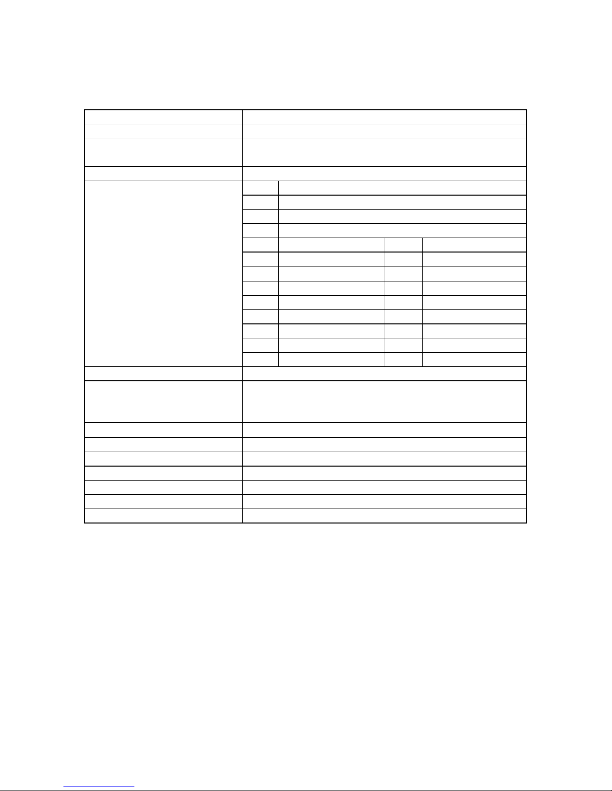
Table 6-2 Test Equipment Required
Nomenclature Manufacturer Model
Network Analyzer Agilent 8753 ET
Spectrum Analyzer Agilent 8560E
Power Meter Agilent E4418B
Power Meter/Sensor Agilent 437B / 8481A
Signal Generator RDL IMD-801D-03A
Directional Coupler Agilent 778D
Attenuator Weinschel Corp 53-30-34
Attenuator Narda 766-20
6.4 Performance Test
Performance test should be performed every 12 months to ensure that the amplifier meets
the operational specifications.
NOTE
The frequencies used in this test are typically within the operating 5 MHz band of 935
MHz to 940 MHz. Select evenly spaced F1, F2, F3, and F4 frequencies that cover the
instantaneous bandwidth of your system.
Figure 6-2
Page 16

14
6.5 Amplifier Performance Test
To perform this test proceed as follows:
Connect test equipment as shown in figure 6-2.
WARNING
DO NOT APPLY ANY RF AT THIS TIME
6.6 Amplifier Spurious Emission Test:
Apply +27 Vdc from the power source. Apply 4-15 Watt continuous random tones from
the RDL to the MAF 900-60S MCPA. Composite power will be 60 Watts measured from
the Power Meter. Setup Spectrum Analyzer for Center Frequency (937.00 MHz), Start
Frequency (930 MHz), Stop Frequency (945 MHz) Span (200 kHz) RES BW (1.0 kHz)
Video BW (1.0 kHz) Measure and record data on Table 6-3.
6.7 Gain Test:
Disconnect spectrum analyzer from the MAF 900-60S. Connect Network Analyzer to
MCPA.
Set Network Analyzer as follows:
a. Normalize Network Analyzer for gain and return loss.
b. Set start frequency to 935 MHz. Set stop frequency to 940 MHz. Setup Network
Analyzer for 2- channel measurement. Set markers to 935 MHz, 937 MHz, 940
MHz.
c. Adjust input power of Network Analyzer to measure 60 watts on the Power Meter.
d. Measure and record amplifier gain on Table 6-3.
e. Set marker to 935 MHz scroll marker (delta) across bandwidth to 940 MHz.
Measure Gain Flatness and record on table 6-3.
f. With Network Analyzer setup for 2-channel operation measure return loss using S11
data Record on. Table 6-3.
Page 17

15
Table 6-3 MAF 900-60S MCPA Test Data Sheet
(
)
(
)
(
)
(
)
Date_________________________
Module S/N___________________
TEST CONDITIONS:
Load and Source Impedance: 50 Ohms
VSWR: < 1.2:1
Supply Voltage: +27 Vdc
Temperature: Room Temperature
TEST SPECIFICATION MIN MAX DATA
Spurious
Emission
RF Gain Voltage = +27 Vdc
Gain Flatness Voltage = +27 Vdc
Input Return
Loss
PASS FAIL
Voltage = +27 Vdc
P
out = 15 Watts
per channel
935 MHz-940MHz
P
out = 60 Watts
935 MHz-940MHz 58 dB
P
out = 60 Watts
935 MHz-940MHz ±0.5 dB
Voltage = +27 Vdc
P
out = 60 Watts
935 MHz-940MHz -15 dB
-63 dBc
Tested By:
Page 18

16
6.8 Field Replacement of the MAF 900-60S
The MAF 900-60S MCPA can be replaced in the field on the site by a qualified
technician with experience maintaining RF power amplifiers and radio equipment.
To replace a power amplifier module, proceed as follows:
1. Set ON/OFF switch on front of amplifier to OFF position.
2. Loosen the thumbscrews that secure the amplifier to the sub-rack.
3. Slide amplifier out of sub-rack.
CAUTION
When removing amplifier from the sub-rack, it is important to support the amplifier
such that the rear of the module does not suddenly drop when the guide rail
disengages from the rack. A drop such as this could damage the rear of the 21-pin-Dsub connector.
4. Replacement of module is done in the reverse order of removal steps 1-3.
Page 19

17
Section 7 Troubles hooting
7.1 Introduction
This section contains a list of problems that may occur. Paradigm Wireless Systems has
suggested corrective action that may correct the problem. If the suggested corrective
action does not eliminate the problem, please contact your Paradigm Wireless Systems
representative for further instructions.
NOTE
Check your sales order and equipment warranty before attempting to service or repair the
unit. Do not break seals on equipment under warranty or the warranty will be voided. Do
not return equipment for warranty or repair service until proper shipping instructions are
received from the factory.
7.2 Troubleshooting
Refer to Table 7-1 for troubleshooting suggestions:
Symptom Suggested Action
Inoperative 1.Check for proper power supply voltage.
2.Verify all RF connections.
3.Contact your Paradigm Wireless Systems representative.
Over Heating Shut Down 1.Check for operation of fans on sub-rack assembly.
2.Check for debris in heat sink
3.Check air conditioning/venting unit for proper operation.
4.Contact your Paradigm Wireless Systems representative.
Over Power Shut Down 1.Verify host system radio output power level.
2.Verify sub-rack input attenuation.
3.Contact your Paradigm Wireless Systems representative.
7.3 Return for Service Procedures
When returning products to Paradigm Wireless Systems, Inc. the following procedures
will ensure response.
7.3.1 Obtaining an RMA (Return Material Authorization)
A RMA number must be obtained prior to returning equipment to the factory
for service. Please contact your Paradigm Wireless Systems representative to
obtain this number. Failure to obtain this number may result in delays in
receiving repair service.
7.3.2 Repackaging for Shipment
To ensure safe shipment of the amplifier, it is recommended that the packaged designed
for the amplifier is used. The original packaging material is reusable.
 Loading...