

Page 1

REPORT RC055097/28116
APPENDIX A
SERVICE/OPERATING MANUAL
Page 2

MAF800-100S
MULT I-CARRIER
POWER
AMPLIFIER
USER MANUAL
Page 3

Ta ble Of Con tents
Page
Section 1 No.
General Description..............................................................................................................1
Section 2
Specifications........................................................................................................................2
Section 3
Multi-Carrier Power Amplifier Principals of Operation.......................................................3
Principals of Operation.........................................................................................................4
Principals of Operation.........................................................................................................5
Principals of Operation…………………………………………………….6
Section 4
Operating Instructio ns...........................................................................................................7
Operating Instructio ns………………………………………………………8
Section 5
Installation Instructio ns.........................................................................................................9
Installation Instructio ns........................................................................................................10
Installation Instructio ns........................................................................................................11
Section 6
Maintenance.........................................................................................................................12
Maintenance.........................................................................................................................13
Maintenance.........................................................................................................................14
Maintenance.........................................................................................................................15
Maintenance.........................................................................................................................16
Section 7
Troubleshooting……………………………………………………………17
Page 4

Section 1
Am plifier System Descrip tion
1.1 Introduction
This manual contains information and procedures for installation, operation, and maintenance of Paradigm
Wireless Systems MAF800-100S multi-carrier cellular amplifier. This manual is organized into the
following sections:
Section 1. Amplifier System Description
Section 2. Specifications
Section 3. Principals of Operation
Section 4. Operating Instructions
Section 5. Installation
Section 6. Maintenance
Section 7. Troubleshooting
1.2 General Description
The MAF800-100S is a linear, feed forward power amplifier that operates in the 25 MHz frequency range
from 869 MHz to 894 MHz. The average output power of the amplifier is 100 Watts average AMPS,
CDMA, CDMA 2000, 1xEV-DO, GSM, TDMA, and EDGE. The amplifier is designed to operate in a
maximum of two continuous modulations or a total instantaneous bandwidth of 25 MHz. The amplifier can
simultaneously transmit multiple frequencies, with a better than –13 dBm third order intermodulation
distortion. The amplifier is designed and suited for use in CDMA, TDMA, EDGE and GSM radio base
stations. A sub-rack is employed to combine the outputs of up to (4) MAF800-100S amplifiers. Each plugin module operates in parallel to produce a high peak output power and fail safe redundancy for trouble free
operation with minimum maintenance. A multi-color LED detects when a fault condition has occurred
within the amplifier. The LED will turn from GREEN to RED during an amplifier fault condition.
Each amplifier has a status connector that allows the host system to monitor the amplifier module
performance. Monitoring of the amplifiers is done through the D-subminiature connector on the back of the
MAF800-100S amplifiers. The front panel of the MAF800-100S amplifier has an ON/OFF circuit breaker.
Primary +27 Vdc power for the MAF 800-100S amplifiers is provided through the sub-rack assembly.
The sub-rack contains the fan assembly for cooling each amplifier. Cooling fans are used to pull air through
the heat sinks. Air movement across the heat sinks dissipates the heat generated by the amplifiers. Constant
airflow ensures the amplifiers performance to specifications.
Section 2
Gain Variation over Temperature 0.3 dB
MAF800-100S Electrical Specification
Parameter Specification
Frequency 869-894 MHz
RF Gain 58 dB
Gain Flatness 0.5 dB
Intermodulation Distortion
≤
-13 dBm
1
Page 5
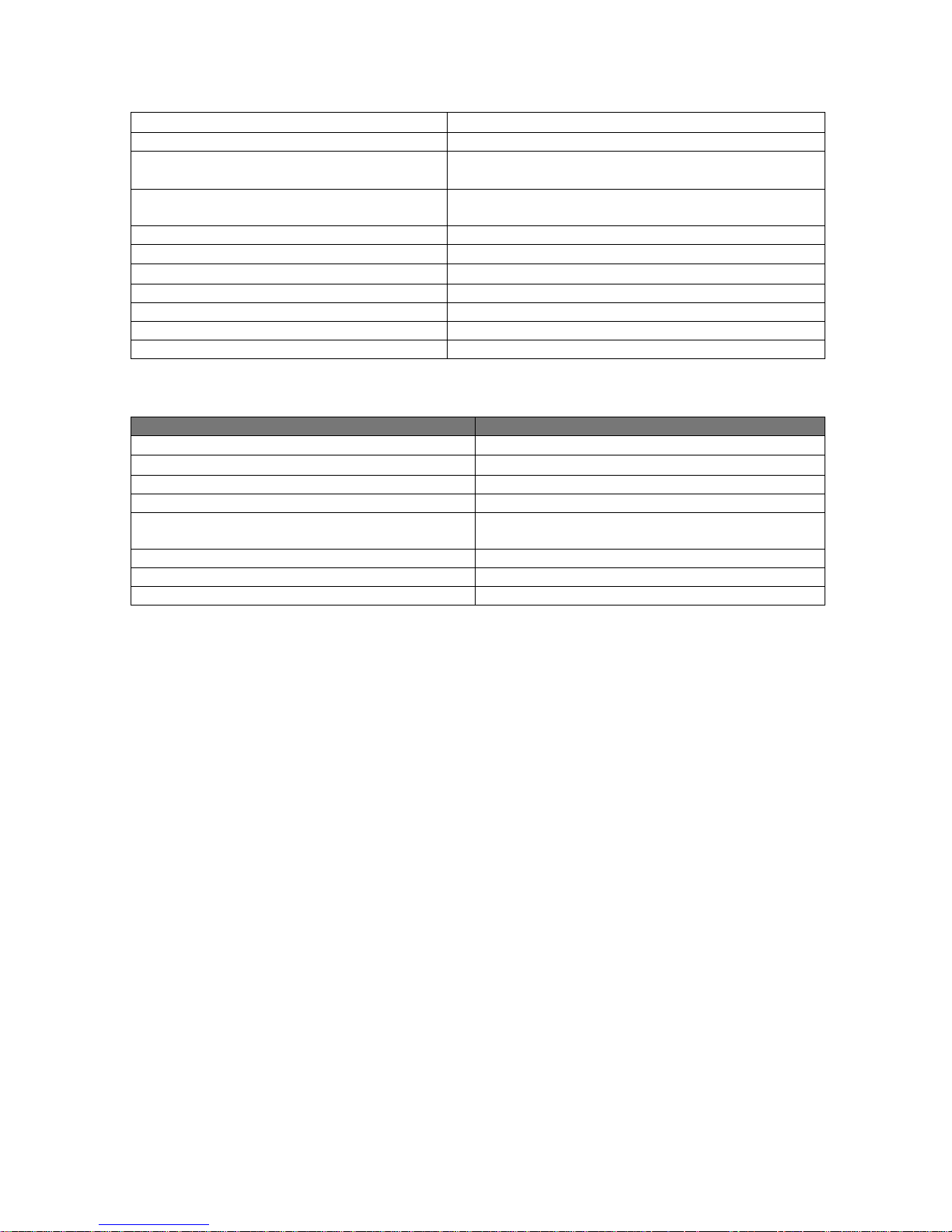
Out of Band Spurious
Input Power -4 dBm
Output Power 100 Watts
Modulation Type AMPS, CDMA, CDMA 2000, TDMA, EDGE, GSM, 1x
Operating Instantaneous Bandwidth 25 MHz
Input Return Loss
Output Return Loss
Output Protection Mismatched Protected
Duty Cycle Continuous
Vd c Input P o wer +2 7 Vd c
Operating Current 24 amps per amplifier
≤
-13 dBm
EV-DO
≥ 15 dB
≥ 15 dB
MAF800-100S Environmental Specifications:
Parameter Specification
Operating Temperature
Storage Temperature
Operating Humidity 5%- 95% Relative Humidity (Non-condensing)
Storage Humidity 5%-95% Relative Humidity (Non-condensing)
RF Input / Output Connector D-Sub, Hybrid, Plug-in Type RF Connector: PKZ
Status / Alarm / Control / DC Input Connector 21 Pin D-Subminiature Combo Connector
Dimensions
Weight
0° C. to 50° C.
-40° C. to + 80° C.
26-0020 series straight plug (Phoenix Co.)
Section 3
Principals of Operati on
3.1 In troduction
This section contains the functional description of the MAF800-100S multi-carrier power amplifier.
3.2 RF Input Signal
The maximum composite input power shall not exceed – 4 dBm. The reference source signal shall not
exceed the base station manufacture minimum requirements for intermodulation distortion. For proper loop
balance, the out of band components of the input signal shall not exceed –40 dBc. The input VSWR should
be 2:1 maximum
3.3 RF Output Load
The load impedance should be equal to or better than 1.5:1 in the operating band for good power transfer to
the load. If the amplifier is operated into a filter, it will maintain its distortion characteristics outside the
signal band even if the VSWR is infinite. Provided the reflected power does not exceed one-watt. A
parasitic signal of less than one-watt incident on the output will not cause distortion at a higher level than
the normal forward distortion
2
Page 6

3.4 Amplifier Functional Description
The MAF800-100S amplifier is a linear, feed-forward power amplifier that operates in the 25 MHz
frequency band from 869 MHz -894 MHz. The amplifier is designed to operate in an instantaneous
bandwidth of 25 MHz. Each amplifier is a self-contained plug in module and is functionally independent of
the other amplifier module. The amplifier modules are designed for parallel operation to achieve high peak
power output, and for redundancy in unmanned remote locations. Each amplifier in the system can
simultaneously transmit multiple carrier frequencies, at an average total power output of 100 Watts, with
better than –13 dBm intermodulation distortion.
All phase and gain corrections are performed on the signal (s) in the individual amplifier module. Each
amplifier module has an alarm board that monitors the amplifier performance. If a failure or fault occurs in
the amplifier module a multi-color LED will change from GREEN to RED. This will be displayed on the
front of the individual amplifier front panel.
3.5 MAF800-100S Amplifier Module
The amplifier module has an average output of 100 Watts power with intermodulation products suppressed
to better than -13 dBm. The amplifier provides an amplified output signal with constant gain and phase by
adding approximately 25 dB of distortion cancellation on the output signal. Continuously comparing active
paths with passive references, and correcting for small variations through RF feedback control maintain
constant gain and phase. The amplifier module is comprised of:
Preamplifiers
Main Amplifiers
Error Amplifier
Two feed-forward loops with phase–shift and gain controls
DC/DC power regulator
Alarm monitoring, control and LED display lamp
3
Page 7

MAF800-100S Block Diagram
4
Page 8

The main amplifier employs class AB amplification for maximum efficiency. The error amplifier and feed
forward loops are employed to correct signal non-linearity introduced by the class AB main amplifier. The
error amplifier operates in class AB mode. The RF input signals are amplified by a preamp and coupled to
an attenuator and phase shifted by 180 degrees and amplified in the pre-main amplifier. The output from
the pre-main amplifier is fed to the class AB main amplifier. The output from the main amplifier is
typically 100 Watts.
The signal output from the main amplifier is sampled using a coupler. The sample signal is combined with
the main input signal and input to the second feed-forward loop. The error signal is attenuated, phase
shifted 180 degrees, then passed to the error amplifier where it is amplified to a level identical to the
sampled output from the main amplifier. The output from the error amplifier is then coupled back and
added to the output from the main amplifier. The control loops continuously make adjustments to cancel
out any distortion in the final output signals.
The primary function of the 1st loop is to provide an error signal for the 2nd loop. The primary function of
the 2nd loop is to amplify the error signal to cancel out spurious products developed in the main amplifier.
The input signal is amplified by a pre-amplifier and fed to a coupler and delay line. The signal from the
coupler is fed to the attenuator and phase shifter in the 1st loop. The 1st loop control section phase shifts the
main input signals by 180 degrees and constantly monitors the output for correct phase and gain.
The 2nd loop control section obtains a sample of the distortion added to the output signals by the main
amplifiers, and then phase shifts the signals by 180 degrees then feeds the signal to the error amplifier.
There it is amplified to the same power level as the input sample and coupled on to the main output signal.
The final output is monitored by the 2nd loop and adjusted to ensure that the signal distortion and IMD on
the final output is cancelled.
3.6 Main Amplifier
The input and output of the amplifier employ two-stage, class AB amplifiers, which provide approximately
25 dB of gain in the 25 MHz frequency band, from 869 MHz to 894 MHz. The amplifier operates on +27
Vdc, and is mounted directly on a heat sink, which is temperature monitored by a thermal sensor. If the
heat sink temperature exceeds 85° C. a high temperature fault occurs. The alarm logic controls the
transistor bias voltage; this shuts down the amplifier if bias voltage is out of range.
5
Page 9

3.7 Error Amplifier
The primary function of the error amplifier is to sample and amplify the signal distortion level generated by
the main amplifier. The error amplifier cancels out the distortion and IMD when the error signal is coupled
onto the main signal at the amplifier output. The matching signal levels from the error amplifier are
injected back into the main amplifier output reducing any distortion and cancellation of IMD. The error
amplifier is a balanced multistage class AB amplifier. It has 75 dB of gain, and produces up to 65 Watt
output. The amplifier operates on +27 Vdc and is mounted directly on a heat sink.
3.8 Amplifier Status Monitoring
In the main and error amplifier stages, all normal variations are automatically compensated for by the feedforward loop control. When large variations occur beyond the adjustment range of the loop control, a loop
fault will occur. The amplifier will be disabled, and the LED will be RED. The alarms will be sent via the
21-pin connector on the rear of the module to the sub-rack summary alarm board.
3.9 Amplifier Module Cooling
Each amplifier module has its own heat sinks. All main amplifier components are mounted to the heat sink.
Forced air-cooling is used to pull air across the heat sinks for operations in the sub-rack. The fans for this
forced air-cooling is located in the sub-rack assembly. The fans are mounted in the rear of the sub-rack
assembly. Air is pulled from the front of the amplifier and exhausted out of the back of the rack.
3.10 DC Power Distribution
Primary Vdc for the system is provided by the host system to the sub-rack assembly. The sub-rack supplies
the +27 Vdc to the amplifier module. The +27 Vdc is supplied directly through the sub-rack power
splitter/combiner board. The amplifier module has a DC/DC converter that converts the +27 Vdc to +12
Vd c , + 5Vd c,
Section 4
4.1 Introduction
This section contains operating instructions for the MAF800-100S Cellular Amplifier System.
4.2 Function of Amplifier Module Controls
Primary +27 Vdc power for the MAF800-100S amplifiers is applied via the 50-amp circuit breaker on the
front panel of the amplifier. A reset switch is located below the LED on the front panel. This switch resets
the amplifier module in the event of a minor alarm. The front panel LED is a multi color LED that changes
from GREEN in normal operation to RED during major or AMBER during minor alarms.
Operating Instructions
6
Page 10

4.3 Alarm Definition
ALARM CATEGORY LED MCPA
MODULE
Over PWR Critical Red Disable High MCPA module output power
Over PWR Critical Red Disable High Input power > - 4 dBm
High TEMP Minor Red Enable Low High temperature detected
High TEMP Critical Red Disable High High temperature detected for longer
VSWR Minor Red Enable Low Reflected power detected at output >7.5
VSWR Critical Red Disable High Reflected power detected at output >26
DC Fail Minor Red Enable Low One of the internal DC voltages
DC Fail Critical Red Disable High Voltage out of range for longer than
DC Fail
(Over
Voltage)
DC Fail
(Over
Voltage)
Loop Fail Minor Red Enabled Low Loop failure detected
Loop Fail Critical Red Disable High Loop failure detected longer than two
Minor Red Disable High +27 Vdc input >28 V detected
Critical Red Disable High +27 Vdc input >28 V. for longer than
MCPA
DISABLE
SIGNAL
CONDITION
> 150 Watts
than two minutes
Watts
Watts
dropped below or exceeded the safe
threshold level
approximately two minutes.
one second after initial detection of
Vd c inpu t > 2 8 V.
minutes.
7
Page 11

4.4 Initial Start-Up and Operating Procedures
To perform initial start-up, proceed as follows:
1. Carefully remove MAF800-100S MCPA series from the shipping carton
2. Place MAF800-100S MCPA into the sub-rack assembly
Caution
When placing MAF800-100S MCPA into sub-rack gently slide MCPA into matting connector. Damage
can occur to matting connector due to abrupt handling of the unit.
Note
All RF connections to the unit will be of 50 ohm. Any changes in impedance will cause severe mismatch
and VSWR to occur. Do not operate the amplifier without a load attached to the output of the sub-rack.
3. Connect all RF input and output cables to the sub-rack.
4. Ensure that source RF power is un-keyed or turned off.
5. Connect +27 Vdc power source to sub-rack
6. Turn ON/OFF switch on the front panel to the ON position.
7. Ensure sub-rack fans are working.
8. Normalize amplifier for 1 minute in ON position. Monitor for alarms on front panel.
9. Before turning on source RF power, verify RF level is set to minimum. High source input level can
damage amplifier.
10. Turn-on 1 channel from source power. Set power level.
Note
•
If operating MAF800-100S MCPA without sub-rack, individual fans, RF attenuation, and
D-Sub connector needs to be assembled for operation. Please contact your representative at
Paradigm Wireless Systems for information.
•
During initial operation of MAF800-100S components of the unit may drift. It is
recommended that a recheck of power levels be done after a 24 hr. period of operation
Section 5
5.1
Introduction
This section contains unpacking, inspection, installation instructions and recommendations for the
MAF800-100S MCPA. It is important that the user perform the following tasks correctly and in good faith.
1. Carefully read all materials in this section prior to equipment unpacking or installation.
2. Also read and review the operating instructions in Section 4 prior to installing the amplifier.
Installation Instructions
8
Page 12

3. If applicable, carefully review the Federal Communications Commission (FCC) rules and
regulation as they apply to your installation.
5.2
El ec trical S er vice Recommendations
Paradigm Wireless Systems recommends that:
•
Proper AC line conditioning and surge suppression be provided on the primary AC input to the +27
Vdc source.
•
All electrical service should be installed in accordance with the National Electrical Code, any
applicable state or local codes, and good engineering practice.
•
Grounding of all equipment should be in accordance to Bellcore standards.
•
Circuit breakers should be thermal type, capable of handling the anticipated in rush current.
5.3 Air Conditioning
Each MAF800-100S MCPA will generate approximately 1900 BTU o f heat. When using more tha n one
amplifier it is recommended that a thermal analysis be performed. Ensuring proper cooling will extend the
Mean Time Before Failure of the unit.
5.3
Unpacking and Inspection
This equipment (as applicable) has been operated, tested, and calibrated at the factory. Carefully open and
remove the MAF800-100S amplifier from the shipping container. Retain all packing material and shipping
container in the event that the unit must be returned to the factory. Please perform the following steps:
9
Page 13

CAUTION
Exercise care in handling equipment during inspection to prevent damage caused by rough or careless
handling.
1. Vis ually inspect the MAF800-100S MCPA for damage that may have occurred duri ng ship ment.
2. Check for evidence of water damage, bent or warped chassis, loose screws, nuts or extraneous
packing material in the connector(s).
CAUTION
Before applying power, make sure that all connectors to the MAF800-100S are secure. Make sure that the
input and output of the amplifier is terminated to 50 ohms. Do not operate the system without a load
attached. Excessive input power may damage the equipment.
If possible, inspect the equipment in the presence of the delivery person.
If the equipment is damaged:
•
The carrier is your first recourse.
•
A claim should be filed with the carrier once the extent of damage is assessed. Careful, immediate
inspection is important if the carrier is suspect of damage.
If the equipment is damaged and must be returned to the factory:
•
Contact your Paradigm Wireless Systems representative.
•
Paradigm Wireless Systems may not accept returns without an RMA.
5.4
Installation Instructions
Model MAF800-100S MCPA is designed for use in a Cellular Radio Base Station. The host enclosure must
permit access to the sub-rack for DC power, RF and alarm cables as well as proper ventilation of sub-rack
the assembly.
WARNING
Verify that all circuit breakers on the MAF800-100S MCPA are in the OFF position before installation in
sub-rack. Turn OFF all external power to the sub-rack before installing MAF800-100S MCPA
1. Install sub-rack into host radio base station and secure it into place using #10 32x1/2 Phillips
screws and #10 flat washers.
2. Connect +27 Vdc using #6 gauge wire. 1- Positive (red) 1- Return/Ground (black).
3. Connect RF IN cable to sub-rack
10
Page 14

4. Connect RF OUT cable to sub-rack.
5. Connect external ALARM interface to external summary alarm board in host radio base station.
6. Before installing the MAF800-100S MCPA into the sub-rack, inspect the 21-pin-D-sub combo
connector on the rear of each amplifier. Verify that all pins are straight, no pins are recessed, and
that the alignment shield is not bent.
WARNING
Do not slam amplifiers into the sub-rack. Forcing the amplifier into the sub-rack at too fast a rate may
cause pins on the 21-pin-D-sub connector of the amplifier to become recessed or broken.
7. Continue installing MAF800-100S amplifiers into sub-rack.
8. Apply +27 Vdc power to sub-rack. Measure with VOM +27 Vdc ± 1.0 Vdc. If the input voltage is
above or below the limits. Check DC power rectifier system.
9. Verify cooling fans on sub-rack is operational.
10. Refer to Section 4 for initial turn-on and checkout procedure.
Section 6
6.1
Introduction
This section contains periodic maintenance and performance test procedures for Paradigm Wireless
Systems MAF800-100S Multi-Carrier Power Amplifier.
Maintenance
NOTE
Check your sales order and equipment warranty before attempting to service or repair the unit. Do not
break the seals on equipment under warranty or the warranty will be voided. Do not return equipment for
warranty or repair service until proper shipping instructions are received from the factory.
6.2
Periodic Maint en an ce
Periodic maintenance is recommended. Table 6-1 lists the intervals at which the task should be performed.
Table 6-1 Periodic Maintenance
Task Interval Action
Inspection
Cables and Connectors 3 months
Inspect signal and power cables for frayed
insulation.
11
Page 15

Check RF connectors ensure
connectors are tight
Performance Tests 12 months
Clean Fans/Heat Sinks 3 months
6.3
Test Equipment Required for Test
Test equipment required to test the amplifier is listed in table 6-2. Equivalent test equipment may be
substituted for any item. Use of a thermistor type power meter is recommended for optimum results.
Annual performance test as outlined in
paragraph 6.4
Inspect for debris. Remove dust with soft
cloth, brush or vacuum cleaner.
NOTE
All RF test equipment must be calibrated and within the calibration date. Any deviation from the nominal
attenuation must be accounted for and factored into all output readings.
12
Page 16

Table 6-2 Test Equipment Required
Nomenclature Manufacturer Model
Network Analyzer Agilent 8753 ET
Spectrum Analyzer Agilent 8560E
Power Meter Agilent E4418B
Power Meter/Sensor Agilent 437B / 8481A
Signal Generator/ESG Agilent E4432B
Directional Coupler Agilent 778D
Attenuator Weinschel Corp 53-30-34
Attenuator Narda 766-20
6.4
Performance Test
Performance test should be performed every 12 months to ensure that the amplifier meets the operational
specifications.
NOTE
The frequencies used in this test are typically within the operating band of 869 MHz to 894 MHz. Select
evenly spaced F1, F2, F3, and F4 frequencies that cover the instantaneous bandwidth of your system.
Figure 6-2
13
Page 17

6.5
Amplifier Performance Test
To perform this test proceed as follows:
Connect test equipment as shown in figure 6-2.
WARNING
DO NOT APPLY ANY RF AT THIS TIME
6.6
Amplifier Spurious Emission Test
Apply +27 Vdc from the power source. Apply 4 RF input signals (CDMA, TDMA, GSM, EDGE) equal to
the total composite operating output power. Setup Spectrum Analyzer for Center Frequency (User
Defined), Start Frequency (User Defined), Stop Frequency (User Defined MHz) Span (User Defined MHz)
RES BW (100 kHz) Video BW (100 kHz) Measure IMD and record data on Table 6-3.
6.7 Gain Test
Disconnect spectrum analyzer from the MAF800-100S. Connect Network Analyzer to MCPA.
Set Network Analyzer as follows:
a. Normalize Network Analyzer for gain and return loss.
b. Set start frequency to 860 MHz. Set stop frequency to 900 MHz. Setup Network Analyzer for 2-
chan ne l mea s ureme n t. Se t ma rke r s to us e r op e ra ting f r e q uency band .
c. Adjust input power of Network Analyzer to measure 50 watts on the Power Meter.
d. Measure and record amplifier gain on Table 6-3.
e. Measure Gain Flatness and record on table 6-3.
f. With Network Analyzer setup for 2-channel operation measure return loss using S11 data Record on.
Table 6-3.
14
Page 18

Table 6-3 MAF800-100S MCPA Test Data Sheet
Date_________________________
Module S/N___________________
TEST CONDITIONS:
Load and Source Impedance: 50 Ohms
VSWR: < 1.2:1
Supply Vol tage: +27 Vdc
Temperature: Room Temperature
TEST SPECIFICATION MIN MAX DATA
Spurious Emission Voltage = +27 Vdc
()
out
P
RF Gain Voltage = +27 Vdc
P
Gain Flatness Voltage = +27 Vdc
P
Input Return Loss Vol tage = +27 Vdc
P
=
()
out
=
()
out
=
()
out
=
57 dB
-15 dB
-57 dBc
±
0.5 dB
PASS FAIL
Tested By: _____________________
15
Page 19

6.1 Field Repl ac em ent of the MAF8 00-100S
The MAF800-100S MCPA can be replaced in the field on the site by a qualified technician with experience
maintaining RF power amplifiers and radio equipment.
To replace a power amplifier module, proceed as follows:
1. Set ON/OFF switch on front of amplifier to OFF position.
2. Loosen the thumbscrews that secure the amplifier to the sub-rack.
3. Slide amplifier out of sub-rack.
CAUTION
When removing amplifier from the sub-rack, it is important to support the amplifier
such that the rear of the module does not suddenly drop when the guide rail
disengages from the rack. A drop such as this could damage the rear of the 21-pin-Dsub connector.
4. Replacement of module is done in the reverse order of removal steps 1-3.
16
Page 20

Section 7
Troubleshooting Shooting
7.1 Introduction
This section contains a list of problems that may occur. Paradigm Wireless Systems has suggested
corrective action that may correct the problem. If the suggested corrective action does not eliminate the
problem, please contact your Paradigm Wireless Systems representative for further instructions.
NOTE
Check your sales order and equipment warranty before attempting to service or repair the unit. Do not
break seals on equipment under warranty or the warranty will be voided. Do not return equipment for
warranty or repair service until proper shipping instructions are received from the factory.
7.2 Troubleshooting
Refer to Table 7-1 for troubleshooting suggestions:
Symptom Suggested Action
Inoperative 1.Check for proper power supply voltage.
2.Verify all RF connections.
3.Contact your Paradigm Wireless Systems representative.
Over Heating Shut Down 1.Check for operation of fans on sub-rack assembly.
2.Check for debris in heat sink
3.Check air conditioning/venting unit for proper operation.
4.Contact your Paradigm Wireless Systems representative.
Over Power Shut Down 1.Verify host system radio output power level.
2.Verify sub-rack input attenuation.
3.Contact your Paradigm Wireless Systems representative.
7.3 Return for Ser vice Pr ocedures
When returning products to Paradigm Wireless Systems, Inc. the following procedures will ensure
response.
7.3. 1 Obtaining an RMA (Ret urn Mat er ial Authorization)
An RMA number must be obtained prior to returning equipment to the factory for
service. Please contact your Paradigm Wireless Systems representative to obtain this
number. Failure to obtain this number may result in delays in receiving repair service.
7.3.2 Repackaging for Shipment
To ensure safe shipment of the amplifier, it is recommended that the packaged designed for the amplifier is
used. The original packaging material is reusable.
17
 Loading...