

Page 1
Operating Instructions
Touch Panel
®
Model No.
TY-TP42P8-S
TY-TP50P8-S
Before connecting, operating or adjusting this product, please read these instructions completely.
Please keep this manual for future reference.
English
TQZW464
Page 2

Table of Contents
Warnings and precautions ........................................................ 3
Warnings ......................................................................... 3
Precautions ..................................................................... 3
Cautions when in use...................................................... 4
Setup location ................................................................. 4
Maintenance ................................................................... 5
If something abnormal happens...................................... 5
Accessories ............................................................................... 6
Touch panel unit ........................................................................ 6
Setup procedure........................................................................ 7
Attachment of the touch panel to the plasma display................ 8
Connection between the computer and plasma display.......... 10
Installation of the USB driver................................................... 11
In case of Windows 98SE ............................................. 12
In case of Windows ME ................................................ 14
In case of Windows 2000 .............................................. 16
In case of Windows XP ................................................. 18
Installation of the Touch Panel Driver ...................................... 21
Uninstallation of the Touch Panel Driver ................................. 22
Setup the program .................................................................. 23
Troubleshooting ...................................................................... 34
Specifications .......................................................................... 35
“Windows” is a registered trademark of Microsoft Corporation (U.S.) in the U.S. and other countries.
(The long title of “Windows” is “Microsoft Windows Operating System”.)
All company and product names are trademarks or registered trademarks of the respective companies.
2
Page 3

Warnings and precautions
Warnings
Do not allow the equipment to get wet.
• If liquid splashes onto the equipment, wipe off with a dry cloth. In the unlikely event that liquid gets inside the
product, unplug the USB cable and contact your dealer. Using the product with liquid still inside may cause a fire,
electric shock or malfunction.
Do not disassemble or modify the equipment.
• Doing so may cause a fire, electric shock or malfunction.
Do not touch the edge of the infrared transmissive filter on the touch panel.
• The edge of the infrared transmissive filter is sharp; you may be injured if you touch it.
Stop using the equipment if anything abnormal occurs.
• In the unlikely event that something abnormal occurs (like the equipment emitting smoke or an odor), unplug the
USB cable and contact your dealer. Using the product in this condition may cause a fire, electric shock or malfunction.
Precautions
When unplugging the USB cable, be sure to grip the connector.
• Unplugging by pulling on the cord may cause cord damage, a fire or electric shock.
Do not place the equipment in a location subject to high humidity or excessive dust.
• Doing so may cause a fire, electric shock or malfunction.
Do not place the equipment in a location where it may be exposed to smoke or steam, or near a stove, kitchen
sink or humidifier.
Do not place the equipment in a location where it may be exposed to direct sunlight.
• Internal temperature may rise and cause a fire.
• This equipment has an optic touch panel that uses infrared rays. Direct sunlight contains infrared rays, and this may
interfere with touch panel operation.
Before moving the equipment, unplug the USB cable.
• Failure to do so may damage the cord, and cause a fire or electric shock.
If the equipment will not be used for a long time, unplug the USB cable.
• To ensure safety, be sure to unplug the USB cable from the socket.
Do not place the equipment on an unstable surface, or in a location subject to heavy vibration.
• If the equipment tips over or falls, it may cause injury or malfunction. In the unlikely event that the equipment is
damaged, unplug the USB cable and contact your dealer. Using the equipment in this condition may cause a fire,
electric shock or malfunction.
Do not lie the touch panel unit face down or place a plasma display on top of it.
• The weight of the plasma display will be applied to the touch panel unit and may cause malfunction.
Do not move the equipment after attaching the touch panel unit to the plasma display.
• The weight of the plasma display will be applied to the touch panel unit and may cause malfunction.
Do not touch components inside the touch panel unit.
• Directly touching components inside the touch panel unit may cause malfunction.
Do not place the equipment in a hot or cold location.
• Using the equipment in an extremely hot or cold location may cause malfunction.
Do not use fluids like benzene, thinner or alcohol to clean the equipment.
• Doing so may cause deformation or ruin the finish by discoloration.
To prevent incorrect operation, do not use other equipment utilizing infrared rays near this equipment.
3
Page 4

Warnings and precautions
Cautions when in use
Always keep the touch panel clean
• This optical touch panel utilizes infrared rays and may operate incorrectly if the infrared transmissive part becomes
soiled. Use a soft dry cloth to clean the infrared transmissive part once every day.
Use a power supply within the rated voltage range
• Be sure that the power supply used conforms to the rated voltage. Use with a power supply exceeding the rating
may cause incorrect operation or malfunction.
Keep the equipment away from locations subject to heavy electrical noise
• Avoid use near equipment that produces excessive electrical noise. Noise may enter the equipment via the power
supply or interface and cause incorrect operation.
Do not touch the infrared transmissive area until starting OS
• After turning on the PC, be sure not to touch the infrared transmissive area on the screen until the PC has completed
the starting of its OS. If this is not observed, device errors may be detected by the PC and subsequently it will not
operate correctly. Should this occur, please restart the PC.
• When connecting or disconnecting the USB cable, be careful not to touch the infrared transmissive area.
Keep foreign matter out of the equipment.
• Do not allow metal objects or combustible material to fall or be inserted into the equipment through openings. Using
the equipment with foreign matter inside may cause problems such as electric shock or malfunction.
Keep away from water
• If water or any other liquid gets inside the equipment it may cause fire, electric shock or malfunction. Do not place
containers that hold liquid (flower vases, fish bowls, cosmetics, chemicals or water) on top of the equipment.
Do not place heavy objects on the equipment.
• The touch panel is made of sheet metal. It is dangerous to place heavy objects on top of it.
Setup location
Before setting up the touch panel, select an optimal location by following the precautions below.
Places where the equipment should not be setup include:
• Locations subject to extremely high or low temperature
• Locations subject to high humidity
• Locations exposed to direct sunlight, and locations near powerful light sources
(This is an optical touch panel, so you should be particularly careful of this point)
• Locations subject to excessive dust
• Locations exposed to shock or vibration
• Locations near emissions of chemicals or steam, or locations where contact may be made with chemicals
• Locations near sources of electrical noise (generators, air conditioners etc.)
4
Page 5

Warnings and precautions
Maintenance
∗Be sure to unplug the USB cable before cleaning the equipment.
Clean the inside of the equipment once a year.
• The equipment is of semi-sealed construction, so dust may eventually accumulate inside. This may cause poor
operation due to a reduction in the level of infrared light available for touch detection. Cleaning frequency will vary
depending on the setup location; if in doubt consult the dealer from whom you purchased the equipment.
• Be careful not to touch the infrared transmissive area on the screen of the plasma display and rub the screen with
excessive force.
Cleaning of the infrared transmissive area
• Once a day, use a soft cloth to wipe off any soiling or debris on the infrared transmissive area. Failure to do so will
cause a malfunction, but on such an occurrence you can restore normal function simply by gently wiping the soiling
off. If soiling is severe, wet a cloth in household detergent diluted in water, wring well, wipe off the soiled part, and
then wipe well with a dry cloth.
• Be aware that if you apply volatile fluids such as thinner, benzene or insecticide, or allow long-term contact with
products containing materials such as rubber or vinyl, the surface of the equipment may discolor or deform. Also, be
careful of wiping with chemically-treated cloths, because such action may cause similar to happen.
If something abnormal happens
If the equipment starts to smoke or emit a strange odor
• It is extremely dangerous to continue using the equipment in such a malfunctioning state.
Immediately unplug the USB cable from the computer, and request the dealer from which you purchased the equipment
for repair.
5
Page 6

Accessories
Check that all accessories are included. Quantities are indicated in parentheses.
Operating Instruction
Books (9)
• English
• French
• German
• Spanish
• Japanese
• Italiano
• Chinese
• Russian
• Ukrainian
USB cable (1)
Length: 2 m
(6.56 ft)
Mounting
brackets [A]
TY-TP42P8-S (4)
TY-TP50P8-S (2)
Mounting
brackets [B]
TY-TP50P8-S (3)
CD-ROM (1)
• USB driver software
• Touch Panel Driver
software
Mounting screws [A]
for Mounting brackets
[A, B]
TY-TP42P8-S (8)
TY-TP50P8-S (10)
Touch panel unit
(Front)
Mounting bracket
for USB cable (1)
Mounting brackets [C]
TY-TP50P8-S (2)
Mounting screws for
USB cable (2)
Mounting screws for
Mounting brackets [C]
TY-TP50P8-S (4)
Left
Right
Light receiver for optional touch pen (TY-TPEN6)
This is for receiving light signals from the special-purpose touch
pen. If this part is obstructed, the equipment will not be able to
correctly receive signals. Note that it protrudes, so be careful
not to hit it.
(touch pen is optional)
(Rear)
6
USB
USB connector
Used to connect to the PC USB connector with
Pen
USB
OFF ON
a USB cable.
Selection switch
ON: Touch pen mode (when using the optional
Pen
OFF ON
touch pen)
OFF: Handwriting mode
Page 7
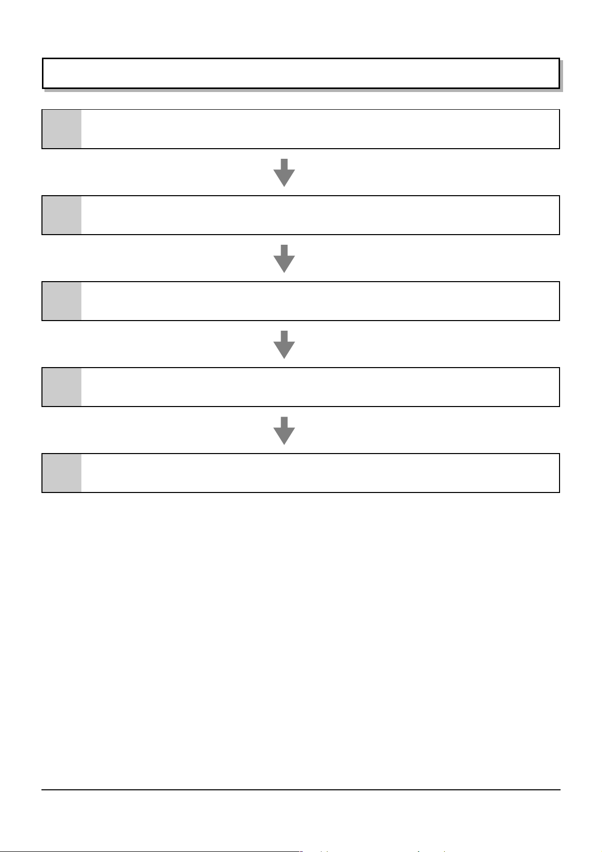
Setup procedure
Attachment of the touch panel to
1
2
the plasma display
Connection between the computer
and the plasma display
................P 8
..............P 10
3 Installation of USB Driver .............. P 11
4 Installation of Touch Panel Driver ..............P 21
5 Setup Program ..............P 23
7
Page 8
Attachment of the touch panel to the plasma display
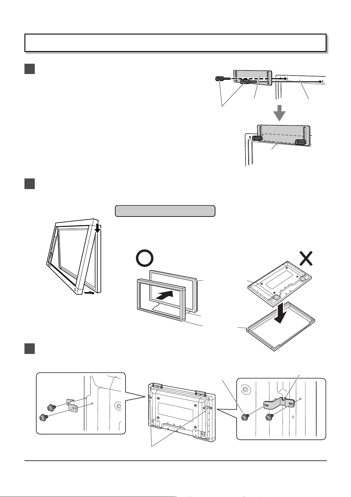
Attach the mounting bracket. [A] (TY-TP42P8-S)
1
(1) Orientate the mounting bracket [A] so that the side lined
with cushion faces the touch panel.
(2) During attachment of the touch panel to the display, lift
the bracket to its highest point so that it does not strike
the display and tentatively fasten to the upper part of 2
points to the left and right.
Attach the mounting bracket. [B] (TY-TP50P8-S)
(1) Orientate the mounting bracket [B] so that the side lined
with tape faces the touch panel.
(2) During attachment of the touch panel to the display, lift
the bracket to its highest point so that it does not strike
the display and tentatively fasten to the upper part of 2
points to the left and right.
Attach the touch panel to the display front surface.
2
Be careful not to strike the touch panel on the display.
Attachment precautions
Mounting
Screw
[A]
Mounting
bracket
[A] or [B]
Pad (Cushion)
To uch panel
(Rear Side)
Never attach a plasma display onto the touch panel by placing the touch panel on
a flat surface. Doing so may damage the infrared sensor on the touch panel.
If you cause a malfunction by attempting attachment in this way, you will be charged
for repairs.
Plasma Display
Stand
Touch Panel
Attach the mounting bracket. [C] (For TY-TP50P8-S Only)
3
Tentatively fasten a fixing screw in the left and right speaker mounting screw holes on the rear of the touch panel
and plasma display to attach the mounting bracket [C].
Screw [C]
Mounting bracket [C]
8
Attach mounting bracket [C]
Page 9
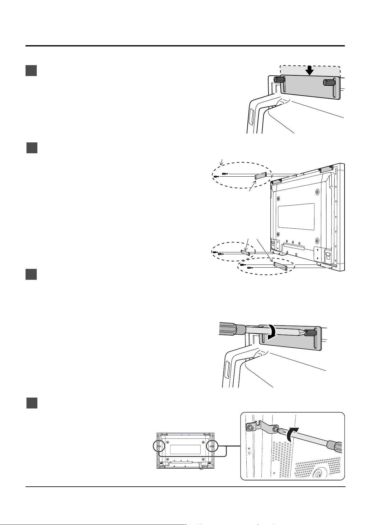
Attachment of the touch panel to the plasma display
Lower the tentatively fastened mounting bracket.
4
Loosen the tentatively fastened bracket mounting screws,
and lower the mounting bracket.
Fasten mounting brackets. [A], [B]
5
Fasten mounting brackets [A], [B] to the display.
•TY-TP42P8-S
Mounting bracket [A] (4 points in total)
TY-TP50P8-S Only
•TY-TP50P8-S
Mounting bracket [A] (2 points in total)
Mounting bracket [B] (3 points in total)
Fasten the touch panel.
6
Fasten the touch panel to the display.
After hand tightening the bracket mounting screws, tighten them further using a flathead screwdriver.
Fasten so there is no large gap between the touch panel and the display front surface.
Be careful not to overtighten the mounting bracket screws as this will cause warping.
Mounting bracket [B]
Mounting bracket [A]
Fasten mounting brackets. [C] (TY-TP50P8-S Only)
7
Secure the mounting bracket [C] by using a Phillips head
screwdriver to tighten the tentatively fastened screw.
9
Page 10

Connection between the computer and plasma display
Connection with computer
1
USB connector
USB
USB cable
Plasma Display (Rear view)
Pen
OFF ON
Computer
Touch Panel
∗ Check that the USB power supply of the computer being used is rated at 500 mA.
(1) Connect the plasma display and computer with the VGA cable.
(2) Turn on power in the following sequence: 1: Plasma Display, 2: Computer.
(3) Switch the plasma display input signal to the computer.
(4) After the computer OS starts up, connect the touch panel and computer with the USB cable.
(5) Insert the CD-ROM containing the USB driver into the CD drive of the computer, start the install wizard, and install
the USB driver software by following the instructions on the screen.
Notes:
• After the computer OS has finished starting up, connect the USB cable.
• If you connect using a USB hub, you must supply power to the USB hub.
• For details on USB driver software setup, see “USB driver setup.” (See below)
• After USB driver setup, you must set up the touch panel driver software. (See page 21)
• If the infrared transmissive part of the screen is accidentally obstructed (such as by your finger) while connecting the
USB, an element defect will be detected. If you use the system in that state, it may respond poorly to touch. If this
happens, remove the USB cable and insert it again. You do not need to restart the computer.
In order to prevent the USB cable from being pulled out, use the
2
following procedure to attach the fixing bracket.
1
Fix the USB cable fixing bracket onto the USB
cable.
Line up the fixing bracket screw hole with the
2
hole on the touch panel.
Fix the bracket in place using the two fixing
3
screws.
Installation of the USB driver
In case of Windows 98 Second Edition (SE) ............ page 12
In case of Windows Millennium Edition (ME) ............ page 14
In case of Windows 2000 .......................................... page 16
In case of Windows XP ............................................. page 18
10
Mounting
bracket for
USB cable
(accessory)
2
1
USB cable
(accessory)
USB
Pen
OFF ON
3
Mounting screws
for USB cable
(accessory)
Page 11

Installation of the USB Driver
Function
The control software provides the following functionality.
• Supplies a software interface for application programs that simulates the output of a mouse. This is achieved by
converting touch panel output data into that which is compatible with the protocol used by the Microsoft serial
mouse input.
This makes it possible to operate existing applications and develop new applications employing the touch panel
as if it were a mouse.
• Enables the changing of touch panel operation settings by using the touch panel setting program.
Operating environment
Personal computer PC/AT compatible machine (DOS/V machine)
Models equipped with a USB port and CD-ROM drive
Compatible OS Windows 98 Second Edition
Windows Millennium Edition
Windows 2000
Windows XP (Service Pack 1 or later recommended)
• The touch panel and control software can be used simultaneously without mutual interference with any pointing
device that does not use the serial port, such as a PS/2 mouse.
• Before installing the control software, the COM port address and interrupts must be set correctly, and the COM
port must be operating correctly.
• You cannot use this software simultaneously with applications that use the COM port (such as hyper terminal).
• If you use this software with applications that require large amounts of CPU time (for example, playing movie
files), problems may be encountered with their operation, such as missing movie frames or delays in mouse
pointer tracking.
11
Page 12

Installation of the USB Driver
Install USB Driver
First, PC is started, and then Windows is started.
The CD-ROM with USB driver software is inserted into the
CD-ROM drive.
Next, touch panel and PC are connected with a USB cable.
(see page 10)
When a USB cable is connected, “Add New Hardware
Wizard” is indicated.
Click on this button.
1
Next, choose this item.
2
In case of Windows 98 SE
Click on this button.
3
Next, choose this CD-ROM drive.
4
Click on this button.
5
The following screen is displayed when the driver file on
the CD-ROM is found and is ready to be copied.
12
Click on this button.
6
Then, the driver file is copied and setup.
Page 13

Installation of the USB Driver
Setup is completed when all the files of the driver are copied.
Click to close this wizard.
7
The new hardware window is displayed again, and the
8
driver for the assumed COM port is installed.
COM port number is confirmed with “Device Manager”
Click on [Start]
1
Double-click on “the system” icon of the control panel,
and open the properties of the system.
The properties of the system are opened.
Then click on the “Device Manager” tab.
2
Double-click “Ports [COM&LPT]”. Confirm that “USB-
3
Serial for Touch Panel V2 (COMx)” is found in “Ports
[COM&LPT]”.
(COMx) is the COM port number for using a touch panel.
As for the COM port number, the setup number varies in
the use environment of the PC.
Next, double-click “Universal Serial Bus controllers”.
4
[Settings]
[Control Panel]
Confirm that “MATSUSHITA USB-Serial Bridge for Touch
5
Panel V2” is found in “Universal Serial Bus controllers”.
Click on this button.
6
The setup of the USB driver is finished.
13
Page 14

Installation of the USB Driver
In case of Windows ME
Install USB Driver
First, PC is started, and then Windows is started.
The CD-ROM with USB driver software is inserted into the
CD-ROM drive.
Next, touch panel and PC are connected with a USB cable.
(see page 10)
When a USB cable is connected, it is recognized as a new
hardware, and a message is indicated.
Choose “Automatic search for a better driver
1
[Recommended]”.
Click on this button.
2
Then, the driver file is copied and setup.
In case of Windows ME
Click to close this wizard.
3
The new hardware window is displayed again, and the
4
driver for the assumed COM port is installed.
14
Page 15

Installation of the USB Driver
COM port number is confirmed with “Device Manager”
Click on [Start]
1
Double-click on “the system” icon of the control panel,
and open the properties of the system.
The properties of the system opens. Next, click on the
2
“Device Manager” tab.
Double-click “Ports [COM&LPT]”.
3
Confirm that “USB-Serial for Touch Panel V2 (COMx)”
is found in “Ports [COM&LPT]”.
(COMx) is the COM port number for using a touch panel.
As for the COM port number, the setup number varies in
the use environment of the PC.
Next, double-click “Universal Serial Bus controllers”.
4
[Settings]
[Control Panel]
Confirm that “MATSUSHITA USB-Serial Bridge for Touch
5
Panel V2” is found in “Universal Serial Bus controllers”.
Click on this button.
6
The setup of the USB driver is finished.
15
Page 16

Installation of the USB Driver
Install USB Driver
First, PC is started, and then Windows is started.
The CD-ROM with USB driver software is inserted into the
CD-ROM drive.
Next, touch panel and PC are connected with a USB cable.
(see page 10)
When a USB cable is connected, it is recognized as a new
hardware, and a message is indicated.
Setup Wizard will start.
Click on this button.
1
In case of Windows 2000
“Install Hardware Device Drivers” is indicated.
Choose this item.
2
Click on this button.
3
“Locate Driver Files” is indicated.
Choose “CD-ROM drives”.
4
16
Click on this button.
5
Page 17

Installation of the USB Driver
“Driver Files Search Results” is indicated.
Click on this button.
6
Driver software is set up, and “Completing the Found New
Hardware Wizard” is indicated.
Click Finish to close this wizard.
7
It is recognized as new hardware once again, and the
8
screen on the left is displayed.
COM port number is confirmed with “Device Manager”
Click on [Start]
1
Double-click on “the system” icon of the control panel,
and open the properties of the system.
The properties of the system opens, click on the
2
“Hardware” tab. Then click on the “Device Manager”
button.
Double-click “Ports [COM&LPT]”.
3
Confirm that “USB-Serial for Touch Panel V2 (COMx)”
is found in “Ports [COM&LPT]”.
[Settings]
[Control Panel]
(COMx) is the COM port number for using a touch panel.
As for the COM port number, the setup number varies in
the use environment of the PC.
The setup of the USB driver is finished.
17
Page 18

Installation of the USB Driver
Install USB Driver
First, PC is started, and then Windows is started.
The CD-ROM with USB driver software is inserted into the
CD-ROM drive.
Next, touch panel and PC are connected with a USB cable.
(see page 10)
When a USB cable is connected, the wizard of the driver
setup starts.
Click on this button.
1
Next, though the following warning message is indicated,
there is no problem.
In case of Windows XP
Click on this button.
2
A driver file is copied and set up.
Setup is completed when all the files of the driver are copied.
18
Click on the “Finish” button to close the wizard.
3
Page 19

Installation of the USB Driver
COM port number is confirmed with “Device Manager”
Click on [Start]
1
Double-click on “the system” icon of the control panel,
and open the properties of the system.
The properties of the system opens. Next click on the
2
“Hardware” tab. Then click on the “Device Manager”
button.
Double-click “Ports [COM&LPT]”. Confirm that “USB-
3
Serial for Touch Panel V2 (COMx)” is found in “Ports
[COM&LPT]”.
(COMx) is the COM port number for using a touch panel.
As for the COM port number, the setup number varies in
the use environment of the PC.
The setup of the USB driver is finished.
[Settings]
[Control Panel]
19
Page 20

Installation of the USB Driver
About the COM port
When it is set up, the USB driver is recognized as a COM port of the PC. Specify this COM number when you don't
use an automatic connection. The setup number varies in the use environment of the PC.
Notes for Installation of USB driver
(Windows 2000/XP)
After the installation of the driver is completed, a new hardware wizard will not be displayed even if a USB cable is
re-connected to the PC.
However, it is recognized as a new hardware, and a setup wizard is indicated when it is connected to a port which
is different from the USB port which did the setup of the driver. In this case, cancel the setup, and connect it to the
USB port, where the driver was setup.
If you unplug and plug USB cable quickly, the PC sometimes does not recognize it.
In that case, please reboot PC.
If running Windows XP, the PC may not automatically recognize hardware on insertion or removal of USB cables.
It is recommended that Windows XP Service Pack 1 (or later) is installed.
20
Page 21

Installation of the Touch Panel Driver
Install Touch Panel Driver
The CD-ROM contains two different types of control
software installers (one for Windows 98SE and Windows
ME, and one for Windows 2000 and Windows XP). Start
the set-up file corresponding to the OS you are using.
Note:
When a previous version driver software has been
installed, first uninstall it and then install the new driver
software.
OS CD-ROM (Installer)
Windows 98SE
Windows ME
Windows 2000
Windows XP
Load the included CD-ROM into a system CD drive. (We
will assume here that this is the D drive.)
(1) Select [Start]
(2) In the [Name] field, input
“D:\English\Win9x_me\setup.exe” or
“D:\English\Win2k_xp\setup.exe”. (Input the
applicable file name for the OS you are using.)
(3) Click the [OK] button.
The setup program will start.
Click this button to continue.
1
Click to start.
2
\English\Win9x_me\setup.exe
\English\Win2k_xp\setup.exe
[Run…].
In the default, it is registered as the startup program.
The driver software will start up automatically the next
time the unit is turned on.
Click to continue.
3
The required file is copied.
Installation ends.
Click to end installation of Touch Panel Driver.
4
Driver software starts when the PC is restarted after
installation is finished.
21
Page 22

Uninstallation of the Touch Panel Driver
Delete “tpdrv” from the “Add/Remove Programs” of the “Control Panel”.
In case of Windows 2000
(1) Click on [Start] [Settings] [Control Panel]
(2) Double-click on [Add or delete applications].
(3) Click on the [Uninstall] tab.
(4) Select “tpdrv” and click on the [Change and delete]
button.
(5) The file delete confirmation screen will be displayed.
Click the [Yes] button.
Uninstall will begin.
Note:
You cannot delete the program using Uninstall if the driver is still running. You must stop the driver program first.
This may be achieved using one of the following two methods.
USB driver software
• Delete the “tpdrv” short cut from the startup folder, and
restart your PC. Then proceed to uninstall the Setup
Program.
• Simultaneously hold down the “Ctrl” + “Alt” + “Delete” keys.
In the confirmation display that appears, select both “tpdrv”
and “tpmenu” and stop them by clicking on “End Task”.
Then proceed to uninstall the Setup Program.
Load the included CD-ROM into the CD-ROM drive, run the program “Un-Installer.exe” on the CD-ROM, and follow
the instructions on the screen to perform uninstall.
22
Page 23

Setup program
The setup program is to set communication ports and various operation modes and to carry out calibration or so on.
Performing setup in the initial state saves the modified contents in “tpdrv.ini” setting file in “C:\Program Files\tpdrv”
folder. Those contents are still valid at the time of the next startup.
Setup of a basic Mode
(see page 24)
Pressing any button displays the setting window
relative to that item to permit changes in set values.
Changes to each item are reflected to the driver
software in operation when closing the window.
Pressing the [Close] button after completion of all
settings records all set values in “tpdrv.ini”.
Adds a Setup Program short
cut onto the task bar.
Cursor Position Fine Adjustment
As the result of carrying out calibration, the mouse
cursor appears at the touched position normally.
If the cursor position is off slightly for some reason,
use these buttons.
Calibration Mode
Target is displayed in the order of upper
left, bottom left and upper right. And
calibration is completed.
Touch a target
(Press any key for cancellation.)
User Setting
(see page 26)
(see page 32)
23
Page 24

Setup program
Setup of basic settings
Communication Port
This sets the COM port of connecting PC.
The port being used for connection with the touch panel is
selected.
Calibration Mode
When “Auto connect” is chosen, driver software detects it
automatically, and it is set up.
If it isn't possible to connect automatically, choose a
connecting port.
Connecting port number will vary depending upon the
environment of PC.
(1) Normal
Please select this mode when you caliblate normally.
(2) Special
Please select this mode if you can not caliblate
normally. (ex:display is zoomed.)
24
Page 25

Palm Touch
Setup of Touch Pen ID
Setup program
(1) Off
Please select this mode in case of touching display
by finger or touch pen.
(2) On
Please select this mode in case of touching display
by plam.
Touch Pen ID indication
ID of the optional touch pen is selected on the touch panel
side.
(1) ID Prohibition
Regardless of the ID number, the signal is accepted.
(2) ID No.1 - 4
Only the signal of the optional touch pen with the
same ID is accepted.
ID of the optional touch pen presently being used is
indicated.
25
Page 26

Setup program
Calibration Mode
Pressing the [Calibration] button on the main window activates the calibration screen to carry out calibration of the
detection of the Touch Panel and PC (in order to place the mouse cursor at the touched position).
Briefly touch the center of the target displayed on the screen in order as they appear.
Target is displayed in the order of upper left, bottom left, and upper right.
To stop calibration, press any key on the keyboard.
Once calibration is carried out, the calibrated value is saved in the setting file. Since the calibrated value is read
from the setting file at the time of the next startup, there is no need to carry out calibration again.
In case of normal setting
Calibration Screen is indicated in order as follows.
∗
To continue the calibration, click on the mouse.
(To terminate, press any key)
26
Touch on the center of the target.
(To terminate, press any key)
Page 27

Calibration Mode
Setup program
Touch on the center of the target.
(To terminate, press any key)
Touch on the center of the target.
(To terminate, press any key)
27
Page 28

Setup program
Calibration Mode
In case of special setting
Calibration Screen is indicated in order as follows.
∗
To continue the calibration, click on the mouse.
(To terminate, press any key)
28
Page 29

Calibration Mode
Setup program
Left click on upper left corner of the display.
(To terminate, press any key)
Left click on lower right corner of the display.
(To terminate, press any key)
29
Page 30

Setup program
Calibration Mode
Can you see three targets within the display area?
Yes Left click
No Right click
(To terminate, press any key)
30
Touch on the center of the target.
(To terminate, press any key)
Page 31

Calibration Mode
Setup program
Touch on the center of the target.
(To terminate, press any key)
Touch on the center of the target.
(To terminate, press any key)
31
Page 32

Setup program
User Setting
The following window is displayed by pushing the user setting button of the Touch Panel setting program menu.
Click Mode (See next page)
Double click Time
Time interval when double-clicking is set up.
Time between the first touch and the second touch is
set. When the second touch is performed within the set
time, it is recognized as double click.
Available time settings are 0.2 to 1.0 seconds within the
interval of 0.2 seconds.
In Windows use “slow” mouse setting when you want to
change this setup.
Double click Area
Sets the effective ranges of double click area. Even if
there is some distance between the first and the second
touches, it can be recognized as double click.
When it is set up “Wide”, it becomes wide, and when it is
set up “Narrow”, it becomes narrow. (When compared
to “Normal” setting.)
Touch Pen Switch
Sets the function switch of the optional touch pen.
(TY-TPEN6)
Right Button
•
By touching a display while pushing the function switch,
it works the same as a right mouse button.
Off
•
The function switch of the touch pen is inoperative.
Right Button Tool
When the operation of the right mouse button is
performed with the touch panel, this tool is displayed.
Touching the tool establishes that only the next touch
corresponds to the pressing operation of the right mouse
button. After that the normal left mouse button operation
is returned.
Left button
operation
Right button
operation
32
Off : No tool is displayed.
Page 33

Setup program
Click Mode
Drag
Touching the touch panel with your finger corresponds to the holding down operation of the left mouse button. Release
of your finger from the touch panel corresponds to the release operation from the left mouse button.
Therefore at the time of releasing the finger from the touch panel, click event occurs.
In addition, when moving the finger, the mouse cursor follows the movement so that the drag operation is made
possible.
Holding the button down
Click on touch
Touching the touch panel corresponds to the single click operation of the left mouse button (ON /OFF of the button).
When touching the touch panel, click event occurs. The cursor does not follow the movement of the finger (i.e. drag
function not available).
Holding the button down
and Releasing the button
Click on Release1
Releasing the finger from the touch panel, click event occurs. While the finger touches the touch panel, no click
event occurs. In addition, the cursor does not follow the movement of the finger (i.e. no drag function is available).
Dragging Releasing the button
No change No change
No change No change Holding the button down
Click on Release2
Releasing the finger from the touch panel, click event occurs. For the dragging function, the cursor does not follow
the movement of the finger. The dragging action will occur only after you release your finger from the touch screen.
Holding the button down No change Releasing the button
and Releasing the button
33
Page 34

Troubleshooting
Before requesting repairs
Symptom
No response at all to
input
Suddenly stops
responding during
operation
Check the USB cable
Check that the USB cable is securely connected.
Check extraneous light
Check whether there is (or might be) any equipment in the surrounding area that
uses a powerful light source or infrared light. The touch panel is an optic type that
uses infrared light. Extraneous light containing infrared radiation may interfere with
operation.
Fluorescent lamps: These are not a problem because they do not produce
Sunlight: This is not a problem if there is no direct exposure.
Incandescent light bulbs: These require caution because they produce the most
Check for incorrect operation due to electrical noise
The microcomputer in the Touch Panel may operate incorrectly if any sources of
electrical noise are close to it. Keep such sources of electrical noise as far away as
possible from the Touch Panel.
Please check the following points.
Check
infrared light.
infrared light. Keep such light sources as far away as
possible from the touch panel.
infrared light.
infrared light. Keep such light sources as far away as
possible from the touch panel.
Response is slow
There are some parts
that do not respond
Check for incorrect operation due to electrical noise
The microcomputer in the Touch Panel may operate incorrectly if any sources of
electrical noise are close to it. Keep such sources of electrical noise as far away as
possible from the Touch Panel.
Check object used for input (not by finger)
Check whether input is being done using an object smaller than a finger.
If input is attempted using an object smaller than 6 mm x 6 mm wide, the coordinates
of the infrared beam may not be detected. Do not attempt to enter data using a
device with dimensions of 2 mm by 2 mm or less.
This may slow detection or result in no detection at all.
Did you touch the infrared transmissive area on the screen before the PC had
completed the starting of its OS?
If so, please restart your PC.
34
Page 35

Specifications
Model Number
Type
Power Source
Voltage
Electric current
Supply system
Touch Panel
Detection system
Panel window (W × H)
Detection range (W × H)
Effective detection range
Resolution (W × H)
Detection pitch
Output system
Number of optic elements (W × H)
Optic element pitch (W × H)
Minimum stylus size (W × H)
Touch pen
USB Interface (USB 1.1)
TY-TP42P8-S TY-TP50P8-S
Optic Touch Panel
DC + 5 V ± 10 %
DC + 5 V Max 400 mA
from USB Bus Power (DC + 5 V Max 500 mA)
Infrared obstruction detection system
945.2 mm × 531.2 mm (37.2 ″ × 20.9 ″) 112 9.2 mm × 645.2 mm (44.4 ″ × 25.4 ″)
920 mm × 516 mm (36.2 ″ × 20.3 ″) 1104 mm × 620 mm (43.4 ″ × 24.4 ″)
Detection range + 1.0 mm (0.04 ″) at the top, bottom, left and right
1,841 × 1,033 ∗1 2,209 × 1,241 ∗1
2.0 mm × 2.0 mm (0.08 ″ × 0.08 ″)
Coordinate output
231 × 130 elements 277 × 156 elements
4.0 mm × 4.0 mm (0.16 ″ × 0.16 ″)
6.0 mm × 6.0 mm (0.24 ″ × 0.24 ″)
Infrared system
Terminal No. and Signal name
(TYPE B)
USB cable length: 2 m (6.56 ft)
-
DATA 2
+DATA
12
43
3
1 Vcc
4 GND
Temperature
Humidity
Resistance to extraneous light
Panel form
External dimensions (W × H × T)
Weight
Extruded material
When operating: 0°C (32°F) to 40°C (104°F) (temperature gradient 25°C (77°F)/hr max.) ∗2
When operating: 20% to 80% (must be no condensation) ∗2
Lateral light: 2,000 lux MIN +20% (angle of incidence: 20°)
Frontal light: 10,000 lux MIN
1,073 mm × 659 mm × 69 mm 1,257 mm × 773 mm × 69 mm
(42.2 ″ × 25.9 ″ × 2.7 ″) (49.5 ″ × 30.4 ″ × 2.7 ″)
(Excluding mounting brackets) (Excluding mounting brackets)
approx. 5.0 kg (11 lbs) Excluding mounting brackets approx. 5.8 kg (12.7 lbs) Excluding mounting brackets
+20%
(angle of incidence: 90°)
Flat panel (Flat type)
Aluminum
Notes:
∗1 When it is used with exclusive driver software.
∗2 This applies to the touch panel alone. When the panel is attached to a device such as a PDP, follow the
environmental conditions for the device being used.
35
Page 36

Specifications
External dimensions
TY-TP42P8-S
Unit: mm (Inch)
External dimensions
TY-TP50P8-S
Unit: mm (Inch)
63.9 (2.5)63.9 (2.5)
659 (25.9)
518 (20.4)
63.9 (2.5)63.9 (2.5)
63.9 (2.5)
63.9 (2.5)
1,073 (42.2)
945.2 (37.2)
797 (31.4)138 (5.4) 138 (5.4)
1,257 (49.5)
1,106 (43.5)
63.9 (2.5)
25.5 (1.0)35.5 (1.4)
63.9 (2.5)
61
(2.4)
8 (0.3)
773 (30.4)
645.2 (25.4)
25.5 (1.0)35.5 (1.4)
61
(2.4)
797 (31.4)230 (9.1) 230 (9.1)
8 (0.3)
Customer’s Record
The model number and serial number of this product can be found on its bottom side. You should note this serial
number in the space provided below and retain this book, plus your purchase receipt, as a permanent record of
your purchase to aid in identification in the event of theft or loss, and for Warranty Service purposes.
Warranty conditions are managed by distributors to meet the standards set by each country. For details, contact
your dealer where you made your purchase.
Model Number Serial Number
Matsushita Electric Industrial Co., Ltd.
Web Site : http://www.panasonic.co.jp/global/
2005 Matsushita Electric Industrial Co., Ltd. All Rights Reserved.
Printed in Japan
M1005T0
 Loading...