

Panasonic TY-SP42PWD3W, TY-CE42PS1, TY-ST42PW1, TY-SP42PM3W, TY-ST42PT3S User Manual
...
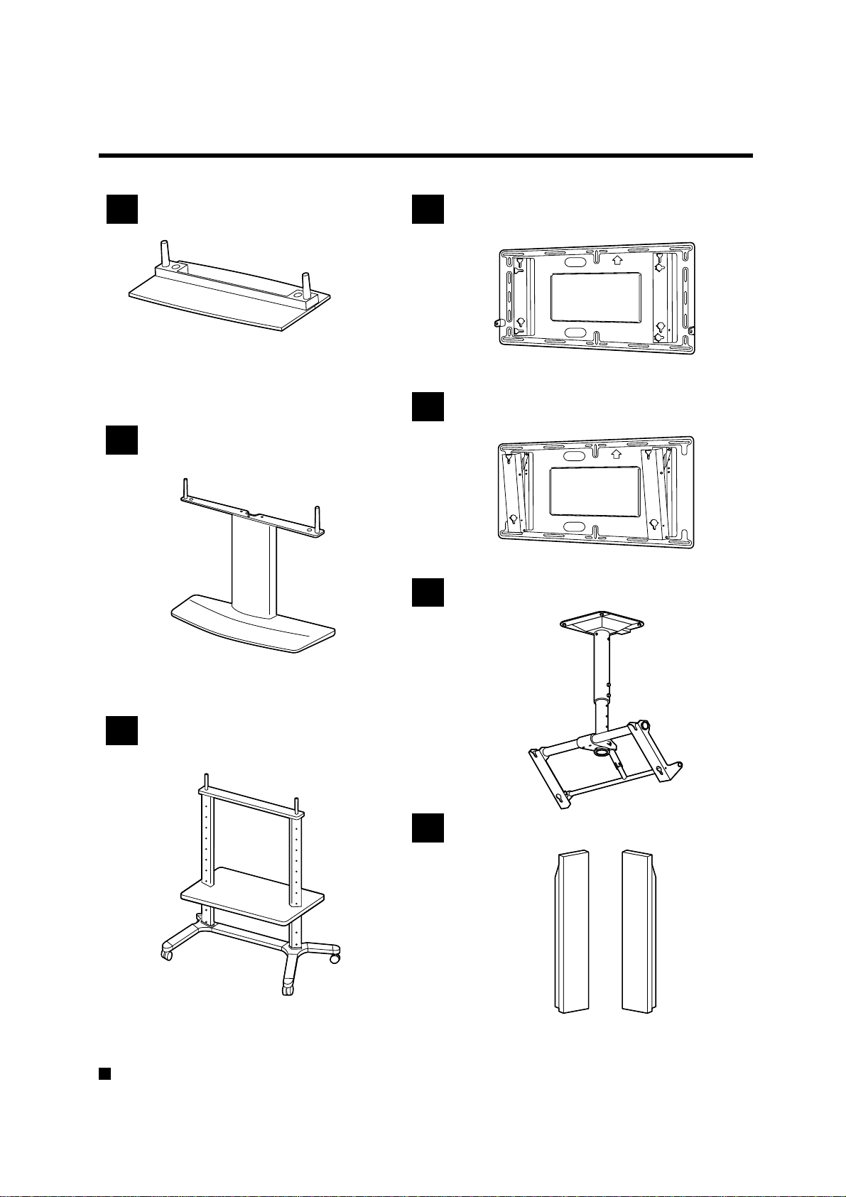
Pedestal
TY-ST42PT3S TY-ST42PT3K
Wall stand
TY-ST42PW1
Mobile stand
TY-ST42PF3
Wall-hanging bracket (vertical)
TY-WK42PV1
Wall-hanging bracket (angled)
TY-WK42PR1
Ceiling unit
TY-CE42PS1
Speakers
TY-SP42PM3W TY-SP42PWD3W

How to use this manual
Some notes on how to read this manual
In this manual, the number such as "1, 2, 3,..." appears to the left of each step.
Go ahead in numerical order.
Indicates a situation where incorrect handling may result in death or serious injury for the person performing the
installation.
Indicates a situation where incorrect handling may result in breakdown or damage to physical objects.
Contains more detailed information than in the steps in the main text. Be sure to read the notes.
Other notes
• More-detailed explanations and supplemental information for the installation procedures are given on the right.
* Be sure to read not just the steps on the left, but the information on the right as well.
• At the very beginning of the installation procedure, there are illustrations for assembling various accessory parts
on the Wide Plasma Display. Refer to them when installing.
• Each installation procedure for accessory parts is preceded by a brief description of the procedure. During the
pro-cedure, refer to the description if necessary.
• Each installation procedure for accessory parts is followed by an explanation of how to remove the Wide Plasma
Display. Refer to this when it is necessary to remove the accessory parts from the Wide Plasma Display and reposition
it.
Before installing
Be sure to read through these instructions before starting the installation.
The installation should be only performed by a professional person.
If any parts are not installed correctly, the display unit may fall, possibly resulting in damage and personal injury.
Failure to follow Warning instructions may result in damage and personal injury.
Make sure that all safety conditions regarding strength at installation are observed.
If the installation strength is insufficient, the display unit may fall and personal injury may result.
Do not install in places which are unable to bear the weight of the display.
If the strength of the floor and wall at the site of installation is insufficient, the display unit may fall, possibly
resulting in damage and personal injury.
A caution indicates special precautions against actions which may result in fire or electric shock.
Do not install in places subject to humidity, dust, oil fumes, condensation or excessive heat.
These factors may adversely affect the Wide Plasma Display, possibly resulting in fire or electric shock.
Do not install the Wide Plasma Display horizontally with the screen facing up, or sideways or upside
down.
Installing the screen other than in the conventional viewing setting may cause heat to build up inside the display
and possibly result in fire.
Two persons are required to install and remove the display unit.
The display unit is heavy and at least two persons are needed to handle it safely. The display unit may drop and
personal injury may result if one person attempts to install it without assistance.
Maintain a space of at least 10 cm respectively at the top, bottom and sides of the display unit and at
least 1.9 cm at the rear of the display unit.
The display unit has air outlet holes at the top and air intake holes at the bottom and rear. These holes must not
be blocked, nor airflow not be obstructed. Otherwise fire may result.
Tools list
The tools in the following tables are necessary for complete assembly.
Before attempting to install the accessories, make sure you have the following tools on hand.
Plus screw driver Clean cloth Drill Measure Level gauge
Pedestal
Wall stand
Mobile stand
Wall-hanging
bracket (vertical)
Wall-hanging
bracket (angled)
Ceiling unit
Optional parts list
Wire or Chain M6 bolt x 6
–––
–––
Pedestal
Wall stand
Mobile stand
Wall-hanging
bracket (vertical)
Wall-hanging
bracket (angled)
Ceiling unit
–
–
–
–
–
–
Accessory list
1
Pedestal
TY-ST42PT3-S
TY-ST42PT3-K
2
Wall stand
4
Wall-hanging bracket (vertical)
TY-WK42PV1
5
Wall-hanging bracket (angled)
3
Mobile stand
TY-ST42PW1
6
Ceiling unit
7
Speakers
TY-WK42PR1
TY-CE42PS1
TY-ST42PF3
For information on the wiring of the Wide Plasma Display after installing accessories, be sure to refer to the
documentation that comes with the Wide Plasma Display.
TY-SP42PM3W
TY-SP42PWD3W
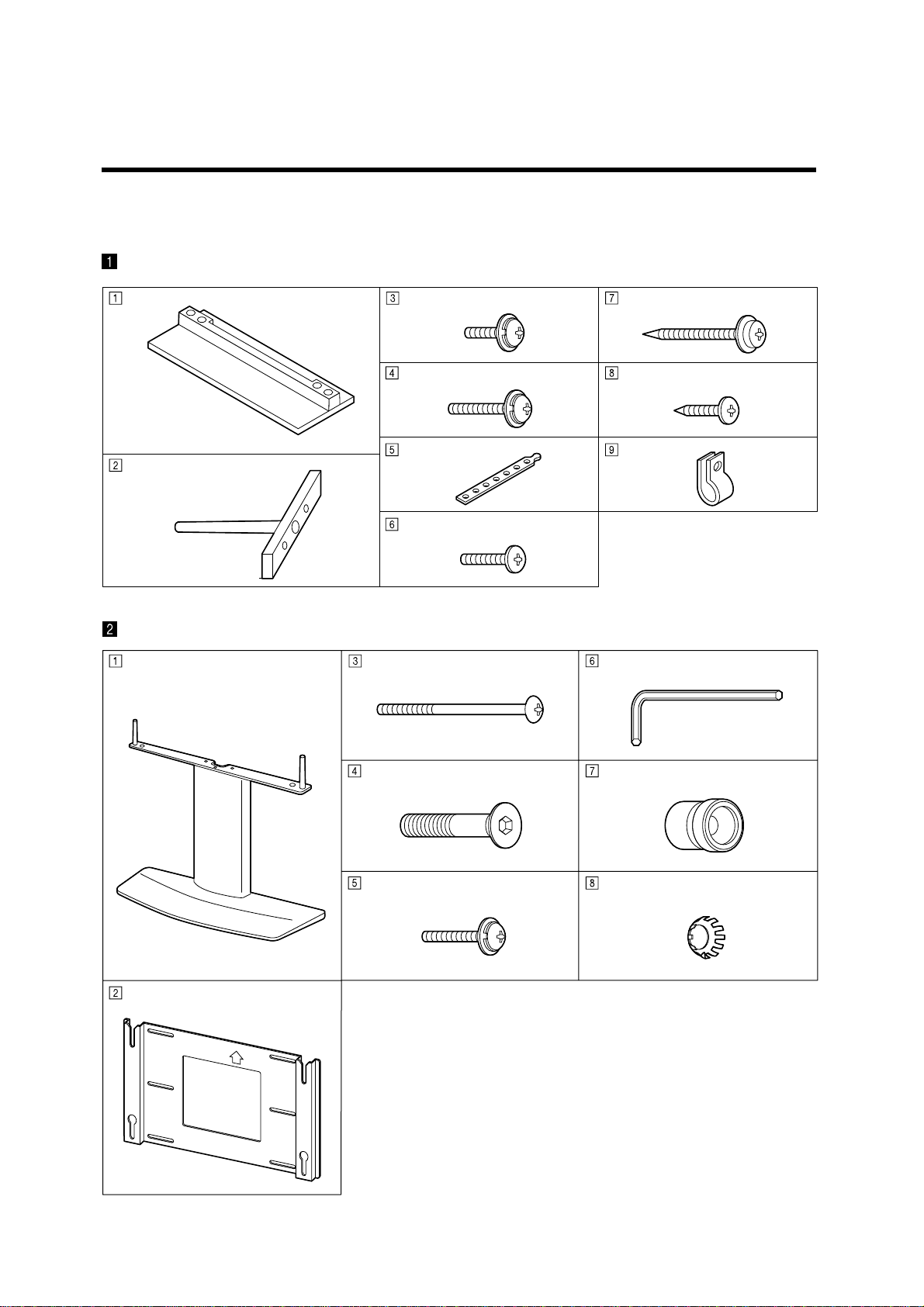
Parts list
Check the part number before performing the installation procedure.
Pedestal
Base Assembly screw(M5-20) x 4
Assembly screw (M5-30) x 4
Band x 2
Pole x 2
Black screw x 2
Wall stand
Wall pedestal
Wood screw x 2
Black screw x 2
Clamp x 4
Allen key (accessory) Fixing screw (M5) x 2
Holding bracket
Pan head bolt with hex socket
(M8-45) x 4
Insulating spacer x 4
Toothed pan washer x 4 Fixing screw (M5) x 2 Assembly
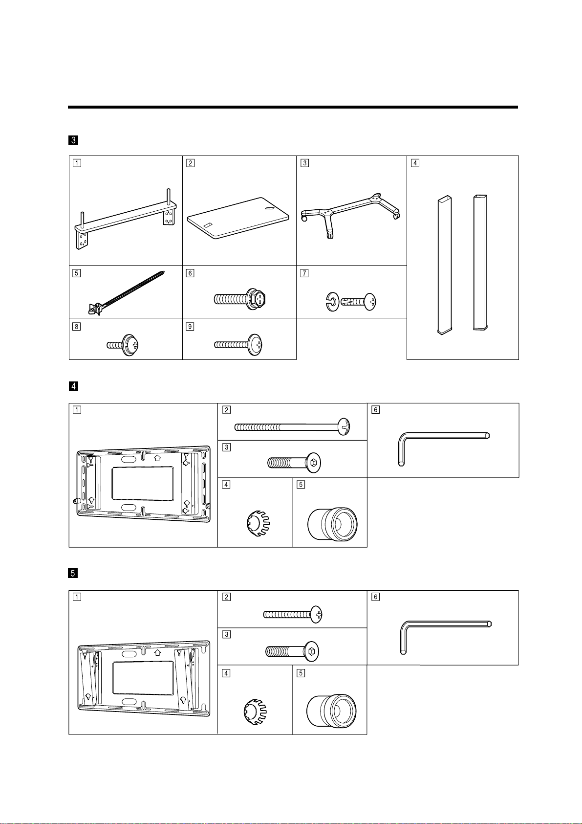
Mobile stand
Holder Shelf Stand base Support x 2
Cable strap x 5 Bolt (M8)x 4
Assembly screw (M5-15) x 4 Assembly screw (M5-30) x 4
Wall-hanging bracket ( vertical )
Wall-hanging bracket unit Fixing screw (M5) x 2
Pan head bolt with hex socket (M8-45) x 4
Tooted pan
washer x 4
Insulating
Assembly screw (M6-16)
and spring washer x 4 each
Allen key (accessory)
spacer x 4
Wall-hanging bracket ( angled )
Wall-hanging bracket unit Fixing screw (M5-35) x 2
Pan head bolt with hex socket (M8-45) x 4
Tooted pan
washer x 4
Insulating
spacer x 4
Allen key (accessory)
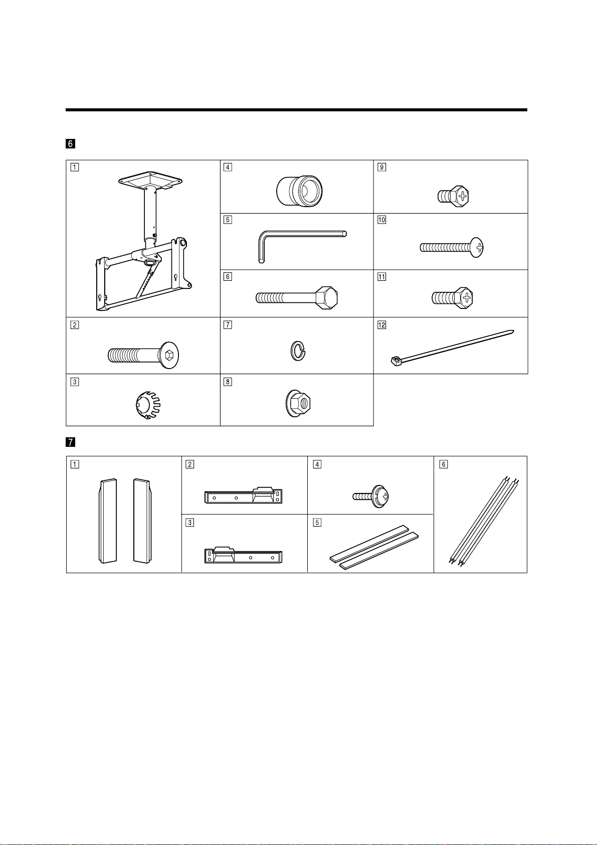
Ceiling unit
Ceiling unit Fixing bolt (M8-12) x 2
(M8-45) x 4
Toothed pan washer x 4
Insulating spacer x 4
Allen key
Fixing bolt (M8-100)
Spring washer
Washer pan nut (M8)
Fixing screw (M5) x 2
Fixing bolt (M8-20) x 2
Cable tie x 2 Pan head bolt with hex socket
Speakers
Speaker x 2
Mounting bracket
(right) x 2
Mounting bracket
(left) x 2
Bracket mounting
Assembly screw (M4-10) x 12
Sponge x 2
Speaker cable
(20 cm) x 2
Points to note during installation
This ceiling unit is for mounting a Wide Plasma Display to a ceiling for viewing purposes.
•
Do not use it for any type of installation other than ceiling mounting.
In order to ensure correct, problem-free operation of the Wide Plasma Display, do not install the Display in any of
•
the following places:
• Next to sprinklers or sensors
• Where it may be subject to vibration or shocks
• Near high-voltage wires or electric motors
• Where it may be in direct contact with air from heaters
When installing this ceiling unit, use a fixing method appropriate to the type of ceiling.
•
Insert the mains plug for the Wide Plasma Display into a mains socket which is close and easily accessible.
•
Provide adequate ventilation so that the temperature around the display does not rise above 40°C (104 F°).
•
If there is insufficient movement of the air inside the displa y, heat may build up inside the display and fire ma y result.
For U.S.A (TH-42PW3 / TH-42PWD3 only)
•
If the connection cable cannot reach the Display when it has been installed to the wall, use the 15 m cable (TYSCP15C03) which is sold separately.
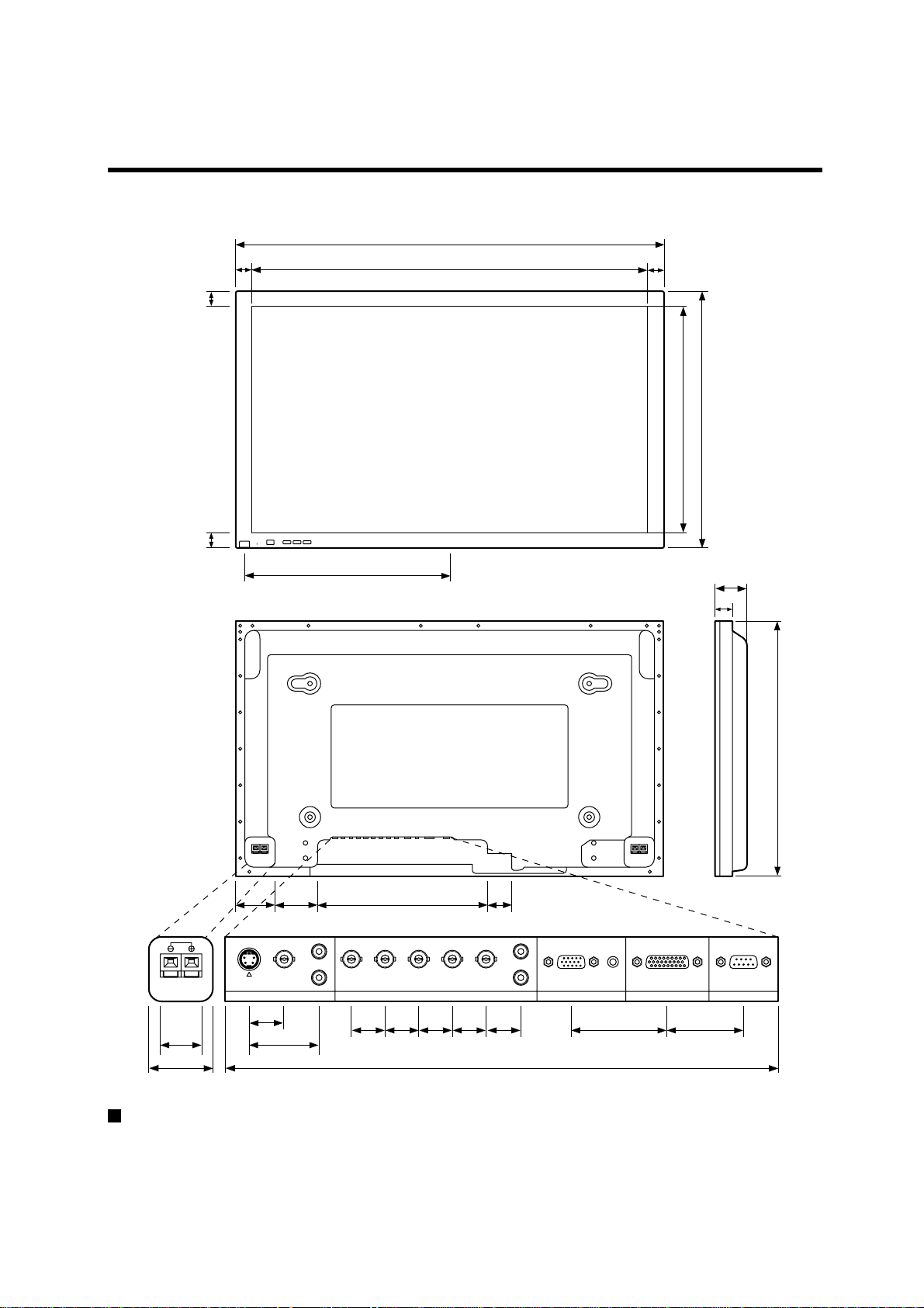
Dimensions of the display unit
Units : mm
1020
50
4646
920
50
518
610
489
98
112.2 65390.9
L
22
S-VIDEO
18.5
AUDIO AUDIO
VIDEO
AV IN
VD HD P
R
18 18 18 18 20 53.86
35.7
R/CR/R PB/CB/B Y/G
70.69 296
89
44
615
L
R
AUDIO
PC INCOMPONENT/RGB IN
SERIALTUNER IN
39.43
To connect the power cord and others, refer to the documentation that comes with the Wide Plasma Display.

Assembly diagram
Pedestal
TY-ST42PT3S
TY-ST42PT3K
CONTENTS
Instruction of the installation...................... 1-2
1.Assembling the pedestal
2.Attaching the pedestal to the display unit
3.Fixing the display unit
.................................... 1-2
.............. 1-2
....................................... 1-3
1-1
Instruction of the installation
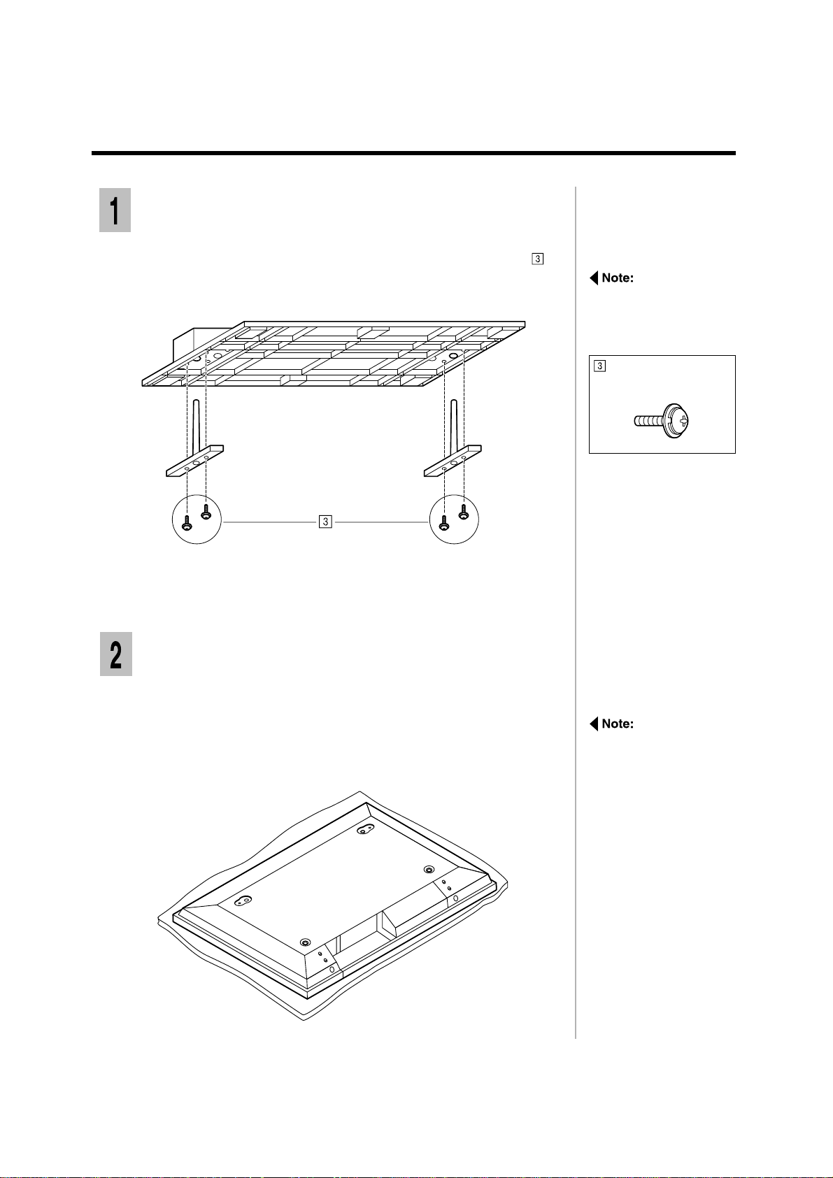
Assembling the pedestal
Put the poles into the outer holes on the base, and fasten the four
1
screws.
Ensure that the poles sit
flush with the bottom of
the base.
Assembly screw
(M5-20) x 4
Attaching the pedestal to the display unit
Spread a clean cloth over a le vel floor or base, and place on it the display
1
unit face down.
Remove the screws and covers.
Keep them in a safe place for possible future use.
Place the display face
down on a cloth clean
and free from other
foregin particles, and
then proceed to the next
step.
1-2
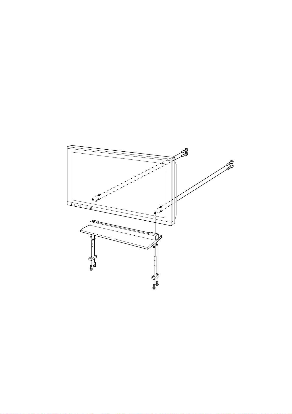
Insert the two poles at the top of the pedestal into the holes in the base
2
of the display unit as shown in the illustration below.
Insert the four screws, two on each side, into the holes in the back
3
of the display unit and screw them into the holes on the inserted poles.
Front
Rear
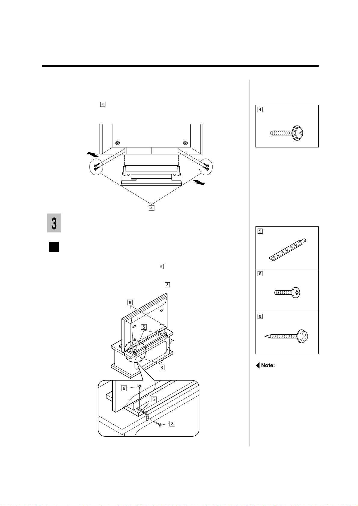
Fixing the display unit
Fixing the display unit to a desk.
Assembly screw
(M5-30) x 4
Band x 2
Screw the bands to the pedestal with screws.
1
Screw the bands to edge of a desk with screws.
2
Black screw x 2
Wood screw x 2
If you are using a
wooden desk, then use
the wood screws.
Use the appropriate
screws for the type of
material of the desk.
1-3
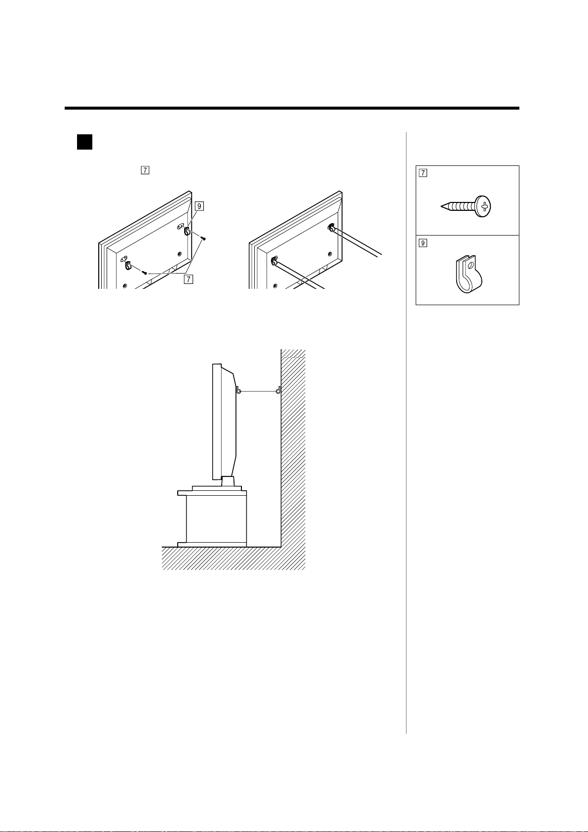
Fixing the display unit to the wall
Insert the screws and clamp into the holes at the back of the display
1
unit.
Use a strong wire or chain commercially available to fix the display unit
2
to a solid area of the wall or pillar.
Black screw x 2
Clamp x 4
1-4
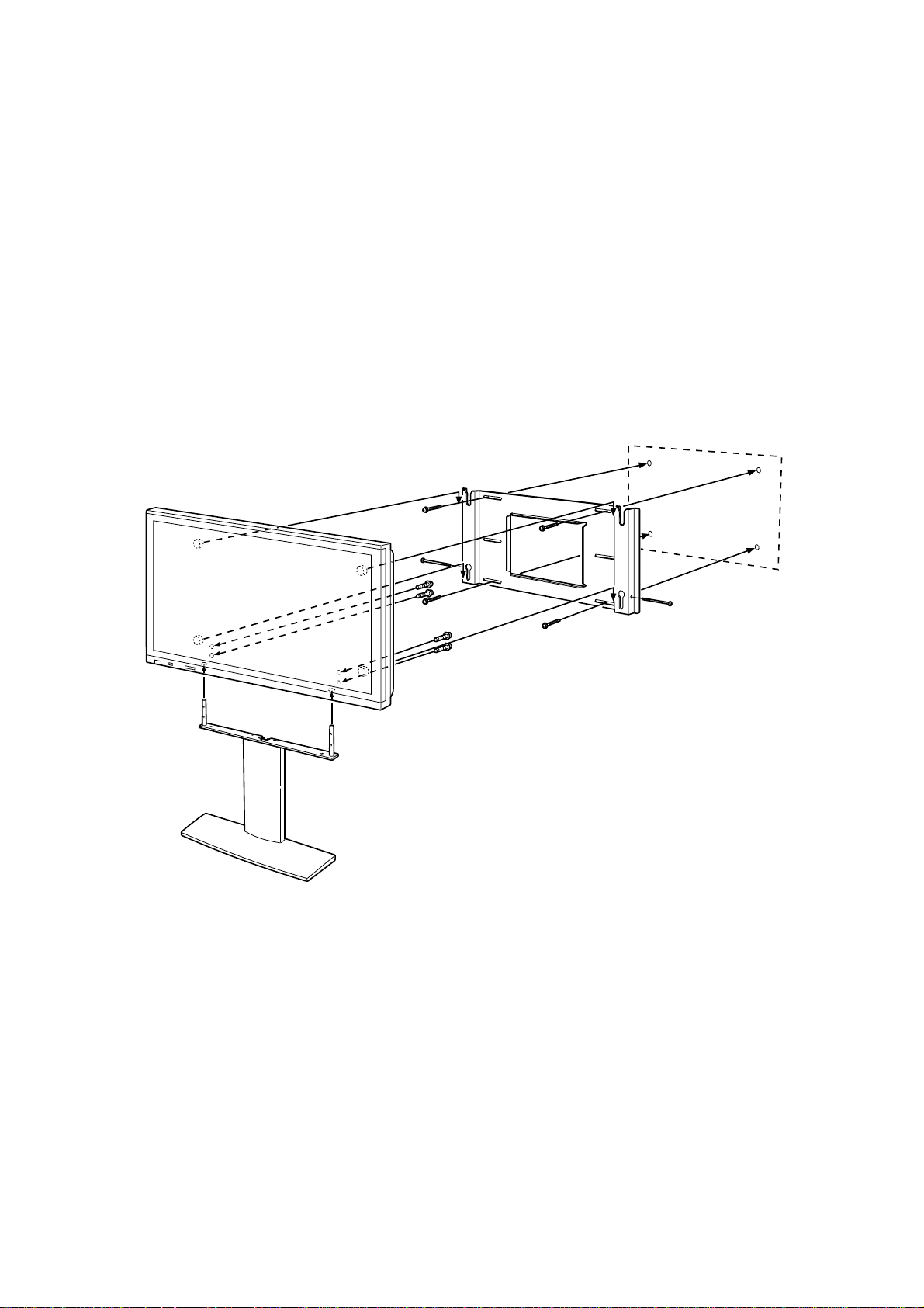
Assembly diagram
Wall stand
TY-ST42PW1
CONTENTS
Description ................................................... 2-2
Instruction of the installation...................... 2-3
1.Assembling the wall stand
2.Fixing the insulating spacers to the display unit
3.Attaching the wall stand to the display unit
4.Fixing the display unit to the wall
Removing the display unit........................... 2-8
.................................. 2-3
...... 2-4
............ 2-6
......................... 2-7
2-1
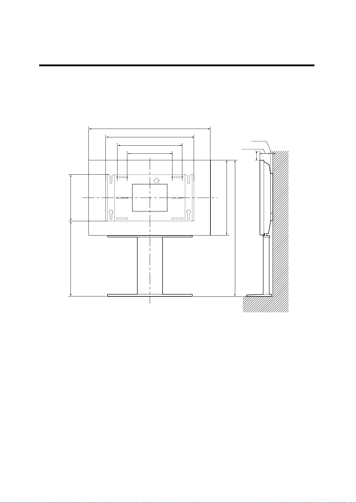
Description
Installation diagram
Units : mm
)
4
/
3
1020 (40
5
744 (2919/64)
560 (22
390 (15
1
/16)
23
/32)
/64)
3
/4)
19 (
89 (333/64)
*100
)
64
/
1
400 (15
)
64
/
5
610 (24
)
64
/
61
1116.5 (43
611.5 (24
* A clearance of at least 100mm at the top of the display unit should be provided.
2-2
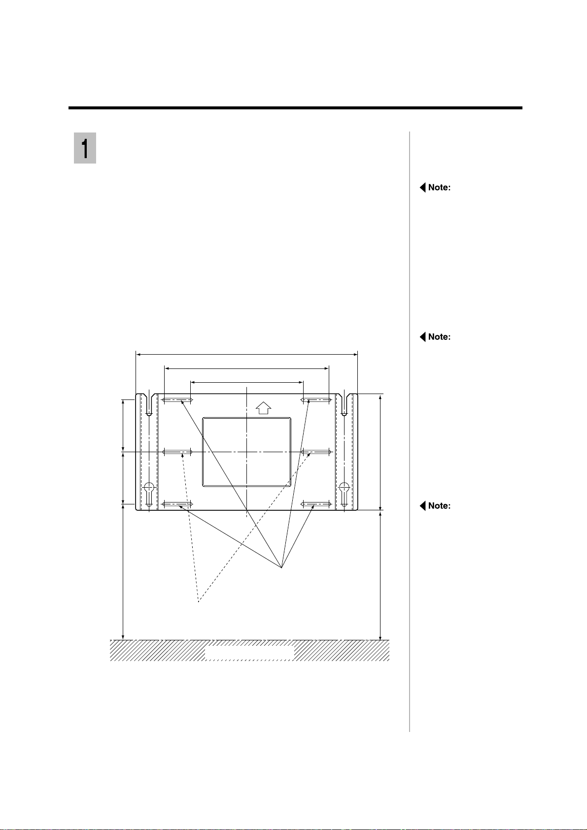
Instruction of the installation
Assembling the wall stand
Check the strength of the installation location.
1
The height measurements marked ** are particularly important. Do not
attempt to set up the pedestal in a location where these dimensions and a
clearance of at least 100 mm at the top of the display unit should be provided.
1) On the wall, measure and mark a height 650 mm above the floor;
2) Measure and mark the location 475 mm horizontally to the right of
the mark you made in 1). Measure and mark points 180 mm and 360
mm above each mark (for a total of six marked locations);
3) Drill a hole at each of the six marked locations on the wall.
Units : mm
744 (2919/64)
560 (22 1/16)
390 (1523/64)
/32)
3
Refer to the holding
bracket installation
measurements in the
drawing left. Ensure that
the wall is able to bear
the weight at each of the
4 upper and lower
installation locations.
Add reinforcement if any
of these locations are
not strong enough.
Ensure an area of at least
650 mm by 1,230 mm in
length at the location
where you plan to install
the holding bracket.
180 (7
/32)
3
180 (7
/8)
7
631.5 (24
**
Wall installation holes
(4 locations)
Spare wall installation holes
(2 locations)
Floor surface
/4)
3
400 (15
/16)
1
611.5 (24
**
The holding bracket has
6 slits through which the
bracket can be fixed to a
wall with screws.
If the wall material does
not allow sufficient
strength by using six
installation holes, use
some of the spare holes.
However, depending on
the construction material
used at the place of
installation, cracks may
develop if the scre ws are
inserted too close to
each other.
2-3
Fix a M6 screw, through any of the slits in the bracket, into the
2
corresponding hole in the wall.
Using a level along the top or bottom edge, ensure that holding bracket is
horizontal.
The holding bracket must always be installed. It prevents the display unit from
falling after installation.
Fix the screws through the slits into the remaining three holes.
3
Provisionally tighten the fixing screws.
4
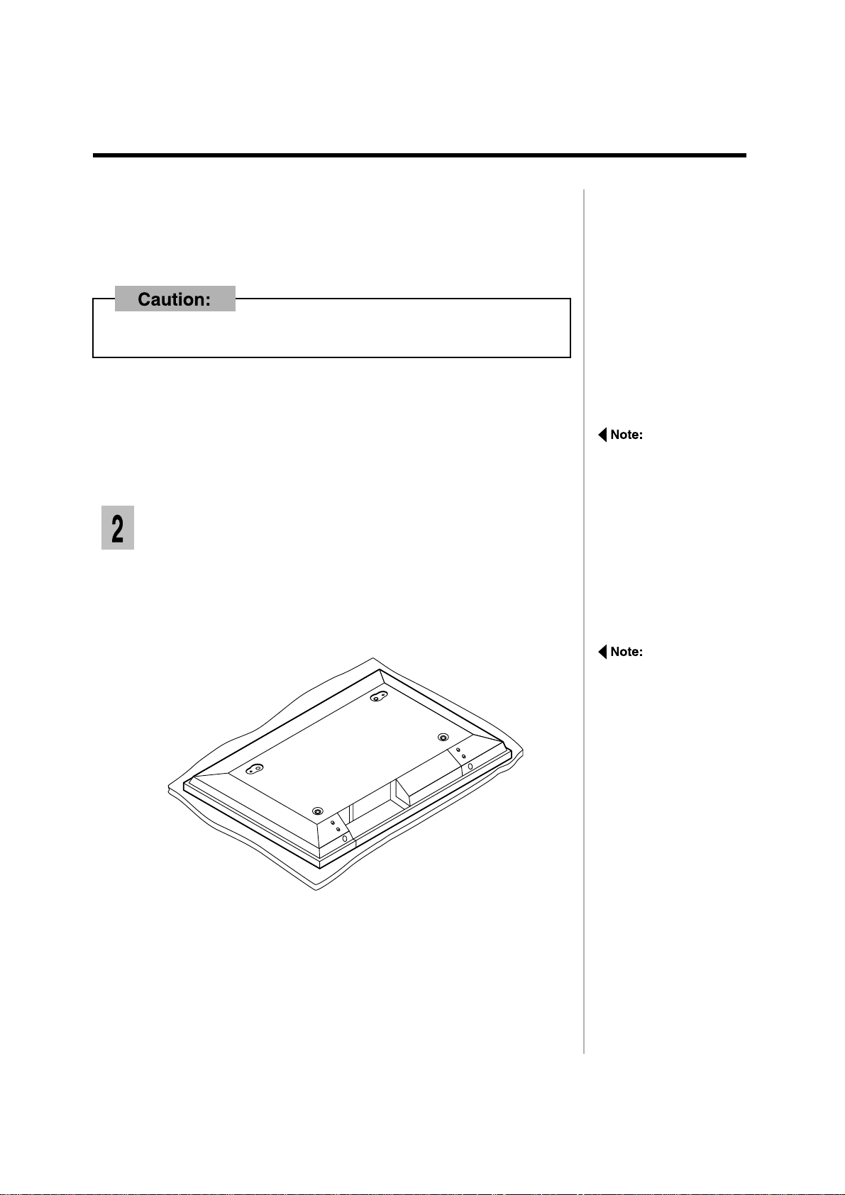
Fixing the insulating spacers to the display
unit
1) Spread a clean cloth over a level floor or base, and place it on the
1
display unit face down.
2) Remove the screws and covers.
Keep them in a safe place for possible future use.
If the screws protrude
more than 5 mm, it will
not be possible to
properly install the
display unit.
Carefully place the Wide
Plasma Display face
down on top of a clean
cloth, which has been
spread over a flat
surface with no other
objects on it, and then
proceed to the next
step.
2-4
 Loading...