

Page 1
Operating instructions
Mode d’emploi
Manual de Instrucciones
Muliti-Scan Colior TFT LCD MONITOR
MODEL TX-D5L31F
TX-D5L31FG
These Operatrng Iristructions ane for units for sale arxf' use in
the United States of America and Canada c«Uy.
Read these Operating Instructions completely before operating this display monitor.
Page 2
IMPORTANT NOTICE CONCERNING POWER CORD SELECTION
The power cord for this unit has been packed separately and has been selected according to the country of
destination and must be used to prevent electric shock. Use the following guidelines if it is necessary to replace
the original cord set.
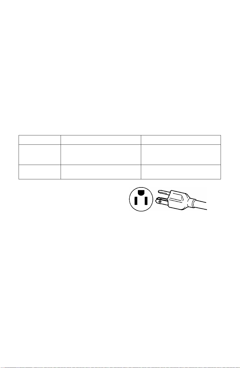
The female receptacle of the cord set must meet CEE-22 requirements and will look like Figure 1:
For the United States and Canada:
In the United States and Canada the male plug is a NEMA 5-15 style (Figure 2) and is UL listed and CSA
labelled. For units which are mounted on a desk or table, type SVT or SJT cord sets may be used. For units
which sit on the floor, only SJT type cord sets may be used. The cord set must be selected according to the
current rating for your unit. Please consult Table A for the selection criteria for power cords used in the United
States and Canada.
For European Countries:
In Europe you must use a cord set which is appropriate for the receptacles in your country. The cord set
Is HAR-CertIfled, and the mark 4 HAR^ will appear on the outer sheath, or on the Insulation of one of the
Inner conductors.
If you have any questions concerning the proper power cord to use, please consult with the dealer where you
purchased your unit.
Table A
Cord Type
SJT 18AWG lOAmps
SVT 18AWG 10 Amps
Size of Conductors In Cord
16AWG 12Amps
14AWG
17AWG 12 Amps
Maximum Current Rating of Unit
12Amps
Figure 1 Figure 2
Federal Communications Commission Requirements
This equipment has been tested and found to comply with the limits for Class B digital devices, pursuant to
Part 15 of the FCC Rules. These limits are designed to provide reasonable protection against harmful
interference in a residential installation. This equipment generates, uses, and can radiate radio frequency
energy and, if not installed and used in accordance with the instructions, may cause harmful interference
to radio communications. However, there is no guarantee that interference will not occur in a particular
installation. If this equipment does cause harmful interference to radio or television reception, which can
be determined by turning the equipment off and on, the user is encouraged to try to correct the
interference by one or more of the following measures:
- Reorient or relocate the receiving antenna.
- Increase the separation between the equipment and receiver.
- Connect the equipment into an outlet on a circuit different from that to which the receiver is
connected.
- Consult the dealer or an experienced radio / TV technician for help.
FCC Warning:
To assure continued FCC compliance, the user must use the provided grounded power supply
cord and shielded interface cable with bonded ferrite cores. Also, any unauthorized changes or
modifications to this monitor would void the useris authority to operate this device.
-1 -
Page 3
CE Conformity
This device complies with the requirements of the EEC directive 89 / 336 / EEC as
amended by 92 / 31 / EEC and 93 / 68 / EEC Art. 5 with regard to “Electromagnetic
C€
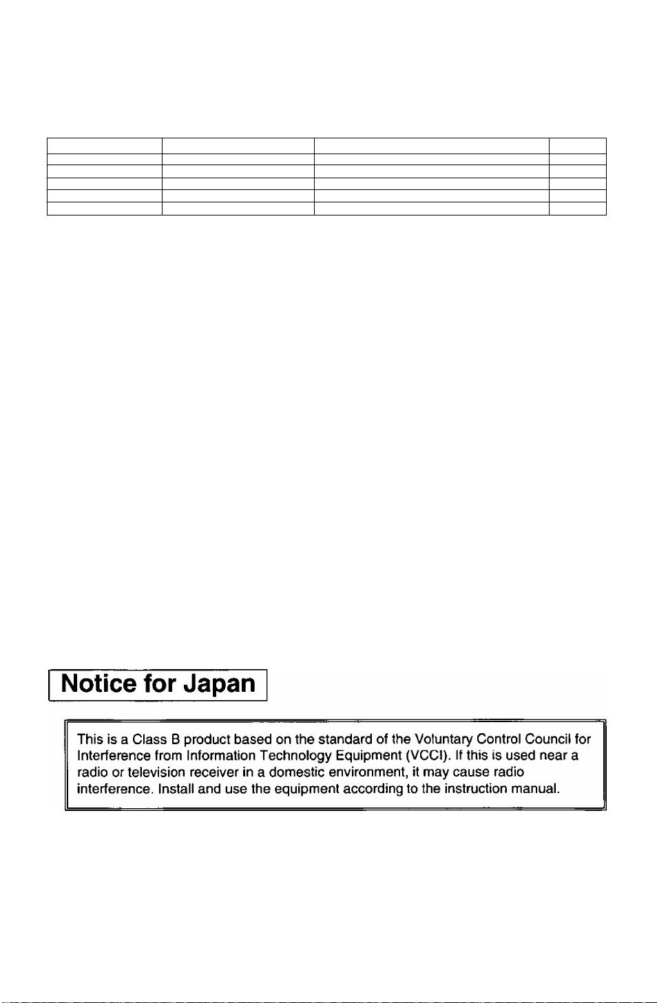
Required item
ESD
RADIATED RF
TRANSIENT F/B #1
LINE HARMONICS
#1 : Satisfies standards with no problems in performance and reliability.
#2 : Effects may appear temporarily on the screen but there will be no problem in reliability.
#3 : There is fear of the product breaking down.
#4 : If a signal cable other than that specified is used, it may be the cause of electromagnetic
Handle correctly in accordance with the instruction manual.
EMI: Electromagnetic Interference ESD : Electrostatic Discharge
RF : Radio Frequency F / B : Fast Burst
As an Energy Star* Partner, Panasonic Computer Peripheral Company has determined that this
product meets the Energy Star® guidelines for energy efficiency.
compatibilité, and 73 / 23 / EEC as amended by 93 / 68 / EEC Art. 13 with regard to "Safety”.
Relative to Standard Value Relative to those Exceeding Standard Value
wave interruption to peripheral devices.
To assure continued CE compliance the user must use the provided 1.5 m shielded
video signal cable with bonded ferrite cores at both ends of the cable.
#1
#2 #3
#1 #3
_
#1
HT
#3
Remarks
#4
Notice for Germany
NOTE:
• For ergonomic reasons, it is recommend not to use blue characters on a dark background. Doing so may
produce insufficient contrast that could lead to eye strain.
German
HINWEIS:
• Aus ergonomischen Gründen wird emfohlen, die Grundfarbe Blau nicht auf dunklem Untergrand zu
venvenden (schlechte Erkennbarkeut, Augenbelastung bei zu geringem Zeichenkontrast wäre die Folge).
Japanese
.iroKBli, (VCCI) ^
UTTii.',,
-2 -
Page 4

I
Danger
To avoid the risk of severe eiectricai shock including death, do not remove covers
(or back) of monitor. No user serviceabie parts are inside. Refer servicing to
qualified service personnel.
Warnings
To prevent risk of eiectric shock and possible fire;
Do not use an extension cord, but aiways piug your monitor's AC iine cord directiy
into a properiy poiarized and grounded socket.
Never piace any object on the AC iine cord or cause the cords to make sharp bends,
or otherwise do anything that can affect the integrity of the cords. Always remove
the line cord from the socket by holding the plug, not the cord.
Do not place anything containing any liquid (even a wet or damp cloth) on the
monitor as the introduction of fluids can create an electrical hazard.
Do not expose the monitor to rain or moisture.
Do not place the monitor with less than the recommended clearance (see
Precautions, 1 Installation Page 4). Do not block the ventilation openings with
anything. Do not insert any objects into the ventilation openings.
Customer’s Record
The serial number of this product is printed on its back cover label.
Note this serial number in the space provided and retain this booklet as a permanent record of
your purchase to aid in identification of the unit in the event of theft or loss.
Model number : TX-D5L31F / TX-D5L31FG
Serial number :
Table of Contents
IMPORTANT NOTICE CONCERNING POWER CORD SELECTION
Federal Communications Commission Requirements
CE Conformity....................................................................................................2
Notice for Germany............................................................................................ 2
Notice for Japan.................................................................................................2
Danger................................................................................................................3
Warnings.............................................................................................................3
Customer’s Record............................................................................................ 3
Table of Contents............................................................................................... 3
Precautions 1) Installation..................................................................................4
Precautions 2) Usage.........................................................................................4
Precautions 3) Product Care..............................................................................4
Features..............................................................................................................5
Specifications................................................................................................... 6
Installation...........................................................................................................7
Connecting USB Devices ..................................................................................9
Pin Assignment.................................................................................................10
External View....................................................................................................10
On-Screen Display (OSD)
Operation Procedure .......................................................................................12
Adjustments .....................................................................................................13
Power Management System............................................................................16
Memories .........................................................................................................16
Timing Specifications........................................................................................17
Trouble Shooting ............................................................................................. 19
Security Port ....................................................................................................20
Technical Support............................................................................................21
Index................................................................................................................21
ALL PRODUCT/BRAND NAMES ARE TRADEMARKS OR REGISTERED TRADEMARKS OF THE RESPECTIVE HOLDERS.
© 1998 MATSUSHITA ELECTRIC INDUSTRIAL Co., Ltd,
...............................................................................
-3 -
......................................
...............
1
1
11
Page 5

I Precautions |
1) Installation
• Install the monitor in a well ventilated place. Avoid exposing to direct sunlight, a
heater, or any other heat source. Heat will adversely affect the cabinets and the
parts inside.
• Position the display unit so that the holes in the cabinet will not be blocked during use.
• Keep the display unit away from the kitchen, bathroom, washing machine, or other
sources of exposed to water, steam or moisture.
• In order to use the display unit safely, use only the supplied AC line cord. The AC line
cord must be used with a properly grounded and polarized power supply socket. The
AC line cord supplied is for the USA (UL) and Canada (CSA) with the display unit.
For use in other countries, make sure the AC line cord meets the safety standards of
the country.
• Place the AC line cord where it will not be subject to stress.
• Use only Panasonic provided accessories or the exact equivalent.
2) Usage
• Pulling on the AC line cord or VGA Signal Cable can damage the display unit
(monitor) and can cause the unit to fall and possibly cause personal Injury.
• Receiving trouble.
If there is a television set or other display unit nearby, keep your display unit as far
away from it as possible. Mutual interference can cause image distortion or noise.
• Long exposure to rubber or vinyl products can stains the cabinet.
• Keep the monitor from physical shock when moving. Be careful of the Active MatrixLiquid Crystal Display (AM-LCD).
• Do not place anything on the monitor.
• Also take good care of the power cable.
Do not place any objects on the power cable. Do not attempt to extend, shorten on tie
it into a knot.
3) Product Care
• Prior to cleaning your display unit, disconnect the VGA Signal Cable from the display
unit.
• Use a clean, soft, dry cloth to clean the outside of the monitor or the AM-LCD surface.
If the monitor or AM-LCD surface is very dirty, wet a clean, soft cloth with neutral
detergent (such as dishwashing detergent) and water, squeeze it tight until almost dry,
wipe the monitor or AM-LCD surface with it, and finish by wiping with a clean dry cloth.
Do not use any solvents.
• Do not rub or strike the AM-LCD with anything hard or harsh as this may scratch, mar
or damage the AM-LCD permanently.
• Do not use a chemical duster or polish-cleaner because it can adversely affect the unit
and peal the paint coat.
-4 -
Page 6

Features
1) Active Matrix-Liquid Crystal Display (*AM-LCD) panel
• The 15 inch (15.0" / 38.1 cm Viewable Image Size) 1024 x 768 pixels (0.297 mm pixel pitch)
AM-LCD pane! with anti-glare hard coating give you a low reflection, anti-static, high-resolution
true color (equivalent of 16.19 million color) and hIgh-contrast display.
2) Easy to use digital controls with on-screen menus
• Digital Brightness and Contrast adjustments are directly accessible form the front panel.
• On-screen menus are available in 5 languages: German, French, English, Italian or Spanish.
• Custom adjustments can be made quickly and easily through the icon-based on-screen menu
utilizing five soft touch buttons on the front panel.
• The on-screen icon-based main menu allows scrolling through the icons with the currently
selected icon being identified on the choice bar located at the bottom of the menu.
3) The LC50S / LC50SG is Windows®95 / 98 Plug & Play compatible
• The LC50S / LC50SG is a Video Electronics Standards Association (VESA) Display Data
Channel (СОС^*^) DDC 1/2B* compatible monitor which meets the Microsoft® / Intel* Plug &
Play Definition. This allows the LC50S / LC50SG to inform a compatible host using Windows 95
/98 of its capabilities.
4) Environmentally Friendly
• LC50S / LC50SG typical power consumption is 50% less than that of a Panasonic CRT color
monitor.
• VESA DPMS (Display Power Management Signaling) computers when used with the LC50S /
LC50SG allows further reduction in power consumption. (See Power Management System
Page 16.)
• The LC50S / LC50SG conforms to the international Energy Star® program standards.
• Meets MPR II and TCO’92 provisions regarding electromagnetic and electrostatic fields.
• Uses less desk space due to the 7.88" (20 cm) depth.
5) Color Temperature control
• There are three color temperatures that may be selected: Normal, 9300K or a User Color.
• User Color allows the white balance of an image to be adjusted by individual control of the
Red (R) and Green (G) and Blue (B) levels. This feature enables color matching of the monitor
colors to the output of a color printer. (See Color selection page 14.)
6) PanaFlat digital multi-scan
• Horizontal frequencies of 30 kHz to 61 kHz and vertical frequencies of 50 Hz to 77 Hz separate
sync can be automatically tracked. The LC50S / LC50SG is suited to VGA. SVGA, XGA and
VESA, timings up to 1024(H) x 768{V) / 75 Hz max. FCC Class B.
• Sixteen user programmable timing memories in addition to the fifteen factory preset timing
selection (Reservations) for image size and position are provided. (See Memories, Page 16
and Timing Specifications, Page 17.)
• Use of a pixel conversion method enables full-screen display of all modes from 640 x 480 /
60 Hz up to 1024 X 768 / 75 Hz separate sync. Full-screen display may not be possible
depending on the input signal timing. (See Auto Size, Page 15 & Timing Specifications, Page 17.)
7) Auto Size & Centering
• Based on the input signal, the adjustments for the H. POSITION / H. SIZE, V. POSITION /
V. SIZE in the 640 x 400 to 832 x 624 modes are performed automatically. H. FINETUNE and
V. FINETUNE are adjusted automatically in the 1024 x 768 mode. Manual adjustment of these
controls may be required when a 1024 x 768 modes is used or depending on the input timing.
8) Self-test menu
• You can test your LC50S / LC50SG by using the MONITOR SELF-TEST menu that is
displayed on the screen. This menu will display if any one five front panel control switches is
pressed and there are no video signals at the input connector of the monitor. (See MONITOR
SELF-TEST, Page 15.)
9) USB Hub in Base
• USB Hub built into tilt base permits the connection of four (4) USB Accessories to a computer
that has hardware and software support of USB. (See Page 9.) One (1) upstream (Type A)
connector & Four USB downstream (Type B) connector provided.
10) Stereo Speakers for High Quality Stereo Sound
• High Quality Sound from bass reflex speakers and Bass-boost circuit technology.
• Stereo speakers (1 W + 1 W).
• External headphone jack is mounted on the front panel of the LC50S / LC50SG monitor.
-5 -
Page 7
Specifications
LCD Screen Size
input signals Video signal
Video Pixel Clock
Viewable image Size Full scan
(H X V, Diagonal)
Connectors Display Signal
Power consumption On 55 Watts (typical)
(VESA DPMS, See Page 16, Stand-by
Power Management System) Suspend < 15 Watts
(No USB peripherals) Off
Controls Right side panel Power Switch (On / Off)
Dimensions (Net) (W x H x D)
Speakers Frequency response
Weight (Net) 7.1 kg (15.7 lbs)
Display Approvals
Standard Signal Cable
Optional Mac Adapter
Operating Temperature
Storage Temperature
Factory Preset Reservation Modes
Windows*95/ 98 Plug & Play
Specifications and design are subject to change without notice.
This product may be subject to export reguiations.
* Number of coiors dispiayed for a given resoiution mode depends on your video source, video memory instaiied and RAMDAC
(Random Access Memory Digitai to Anaiog Converter).
Type TFT Active Matrix Liquid Crystal
Pixel pitch
Coiors*
Response
Contrast Ratio
Viewing angle
Surface
Sync signal (The monitor
cannot be used in the interlaced
mode.)
H-Sync 30 kHz - 61 kHz
V-Sync
Modes 15 Factory Preset (Reservation) Modes (See page 17.)
Resolution (H X V)
Headphone terminal
Audio input terminal
USB terminals
Power supply
Soft Touch Front panel
On screen display
Practical audio output
Power Cable
Other Cables
Tilt Base (Removable) Tilt 0 - 30=
Documentation
Humidity
Humidity 5% to 90% Non-condensing
15" LCD (15.0" / 38,1cm Viewable Image Size)
0.297 mm
Equivalent of 16.19 million colors by error dispersion technology
Fast (23 ms (typical)) Suitable for monitor pictures.
400 : 1 (Typical)
R / L: ± 70 degrees, Up: 55 degrees, Down: 70 degrees (Typical)
Anti-Glare Hard coat
RGB Analog (0.7 Vp-p ~ 1,0 Vp-p, 75 ohms)
H / V separate (TTL), H / V combined,
or Sync-on-Green
50 Hz - 77 Hz
16 User Memories (See page 16.)
80 MHz max.
1024 dots X 768 lines 75Hz N1, FCC Class B, Max.
11.97" X 8.98", 15.0" diagonal 640 x 480 to 1024 x 768
30.4 cm X 22.8 cm, 38.1 cm diagonal 640 x 480 to 1024 x 768
One 15 pin mini D-Sub
3.5 mm diameter stereo mini jack
3.5 mm diameter stereo mini jack
Upstream port x 1
Downstream Port x 4
CEE 22 type 3-pin connector
< 15 Watts
< 5 Watts
Menu key, Left key, Right key, - key, + key, Volume key,
Mute key, Power LED, With direct access to Brightness & Contrast
CONTRAST, BRIGHTNESS, BACKLIGHT, H. POSITION, H. SIZE,
V. FINETUNE**, V. POSITION, V. SIZE, H. FINETUNE**,
COLOR TEMP (Normal color / 9300K / User color), VIDEO LEVEL
ADJ (0.7V-1.0V), DISP. FREQ., LANGUAGE (German, French,
English, Italian, Spanish), AUTO SIZE, RECALL (Factory Settings),
OSD POSITION, PICTURE, VOLUME, MONITOR SELF-TEST
(w / NO SIGNAL Input or SIGNAL ERROR (Out of Range))
**See Page 13 and 14, Menu.
15.16" X 15.39" X 7.88" (385 mm x 391 mm x 200 mm)
80 Hz to 20 kHz
1 W + 1 W (typ)
UL1950, CSA 22.2 No. 950, TUV / GS, NORDIC,
FCC Class B, IC-B, CE / CISPR 22-B, VCCI-B,
MPR II, TCO’92 / NUTEK, IS09241-3 (Ergonomics),
Energy Star®
One 15 pin male mini D-Sub to 15-pin male mini D-Sub (4.92'11.5 meters)
One UL 3 pole (CEE 22 type) (5.91 '/1.8 meters)
USB Cable (5.91 '/1.8 meters), USB DC Cable (0.8' / 0.241 meters)
Audio Cable (5.91 ’/1.8 meters)
operating Instructions & Warranty card
UNIMAC - 82D (Not included)
32 to 95=F (0 to 35=0
5% to 90% Non-condensing
-4to140=F(-20 to 60=0
See Pages 17 and 18.
VESA DDC1/2B (Meets Windows95 / 98 Plug & Play Requirements)
-6-
Page 8
Installation
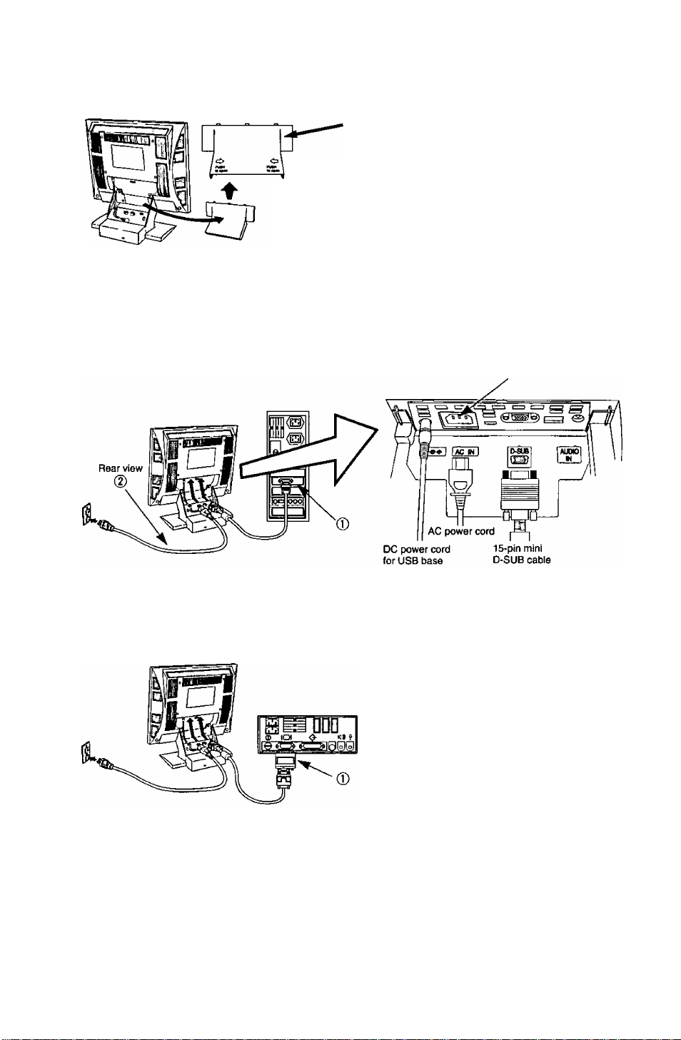
Connection Preparation
Cable storage compartment cover
Connect the signal cable and electrical cord
and then store the cable section that is not
used in this compartment.
Refer to the following figure in advance and remove
the cover of the cable storage compartment.
(Remove the cover while pressing the parts indicated
by the i=>and arrow marks in the figure.)
■ Connecting Procedures
Turn off your computer. Connect the signal and power cables as shown below.
(D Connect the supplied signal cable to the monitor’s port and to the computer video output,
d) Connect one and of the AC power cord to the monitor’s CEE 22 male socket and then the
other end of the AC power cord to a grounded power outlet.
Turn on the monitor, then turn on the computer.
A. IBM PS/2 or PC/AT compatible models
B. Apple computers
(D Use a UNIMAC-82D MAC adapter.
Panasonic MAC adapter
If you need an adapter and one is not provided by your dealer,
call 1-800 PANASYS (1-800-726-2797).
CEE 22 connector
I—Caution:
To prevent the cable from
coming loose, the cable
connectors must be securely
fastened with screws.
----------------
■ Connection of AC Power Supply
If the AC power supply voltage is in the range 100 to 240 V, either 50 Hz or 60 Hz frequency can be
used. There is no AC100 V / 240 V selector switch as selection is automatic.
— Precaution: ----------------------------------------------------------------------------------------------------
• In order to use the display unit safely, use a power cord that is supplied and make sure that it is properly
grounded.
• AC plug cords for the following countries must be used as follows:
For use in other countries, make sure that the AC cord meets the safety standards of each country.
U.S.A
........
UL
Canada....CSA
-7 -
Page 9
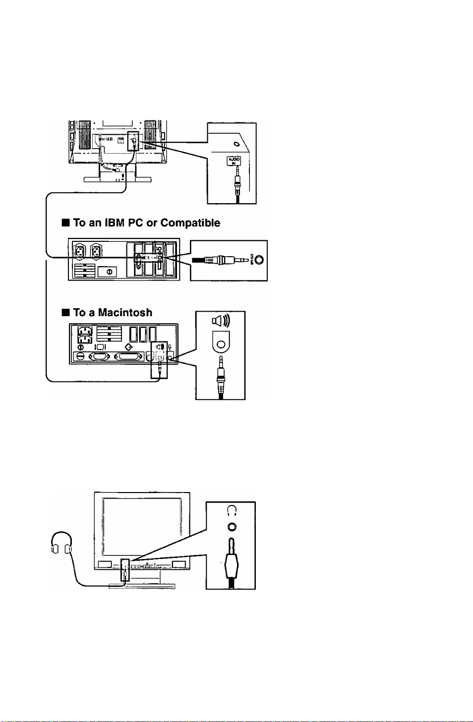
■ Using the Multi-media Functions
Your personal computer must have a audio input / output function.
Always use the accessory cable provided.
Using the Speakers
Prepare the Audio cable (accessory) and connect as shown in the illustration below.
Connect the cable to the AUDIO IN
terminal on the back panel of the main
unit.
Connect the speaker cable to the
AUDIO OUT terminal of the computer.
Connect the speaker cable to the
SPEAKER terminal of the computer.
* The shape of the terminal of your computer may differ from that shown here. In such
case, read the instruction manual for your computer and connect as indicated.
Using Headphones
Prepare the headphones (commercially available) and connect as shown in the illustration
below.
Connect the cable from the head
phones.
Caution:
• If a filter or touch panel is attached to the screen, blocking the speakers, the sound quality
and volume will be affected.
• Volume will vary depending on the headphones, so set the volume as appropriate.
• Interference may occur if the Audio cable is positioned close to the display monitor.
If noise occurs in the speakers or headphones, move the cables away from the monitor.
-8 -
Page 10
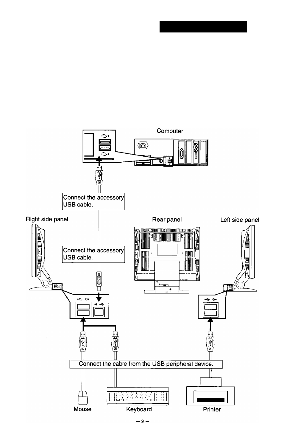
Connecting USB Devices
I Prepare the accessory USB cable provided.
Always use the USB cable that is
enclosed with the unit.
I Connect the USB connector (Type A) to the computer.
I Connect the USB connector (Type B) to the USB UP stream port of the main unit.
I Connect the cable of the USB device being used to the USB DOWN stream port of
the main unit.
USB Cable
e[^)
Type A Connector
Typical Connections
Type B Connector
Page 11

Pin Assignment
Follow the instructions below to connect the LC50S / LC50SG to a computer.
A. Signal connector: 15-pin mini D-sub (PS / 2 or pc / at compatible model)
Connect the signal cable to the 15-pin mini D-sub connector on the display unit.
B. Signal connector: 1 5 -pin D-sub (Apple computer)
Convert a MAC 15-pin D-sub connector to a 15-pin mini D-sub connector using a Panasonic MAC adapter,
and connect it to the 15-pin mini D-sub connector on the display unit.
< REAR PANEL >
Pin assignments of 15-pin mini D-sub connector
Pin number Signal name
1
2
3
4
5
6
7
8
* “VESA”s Display Data Channel (DDC) Standard.
Red signal
Green signal 10
Blue signal
Ground
Open 13
Red signal
ground
Green signal
ground
Blue signal
ground
Pin number Signal name
9
11 Ground
12
14
15
Open
Ground
SDA*
Horizontal
sync, signal
Vertical
sync, signal
SCL*
External View
Dimensions
Width
Height
Depth
385 mm {15.16")
391 mm (15.39")
200 mm (7.88")
Depth w/30 degree tilt angle: 247 mm (9.72")
_j
!
i
1 307.1
C3—^
I
____
_____
H5_
266
_
—ID
___
Tilt range
Down
Up
N-
0 degrees
30 degrees
- ^
- 10 -
H
Page 12
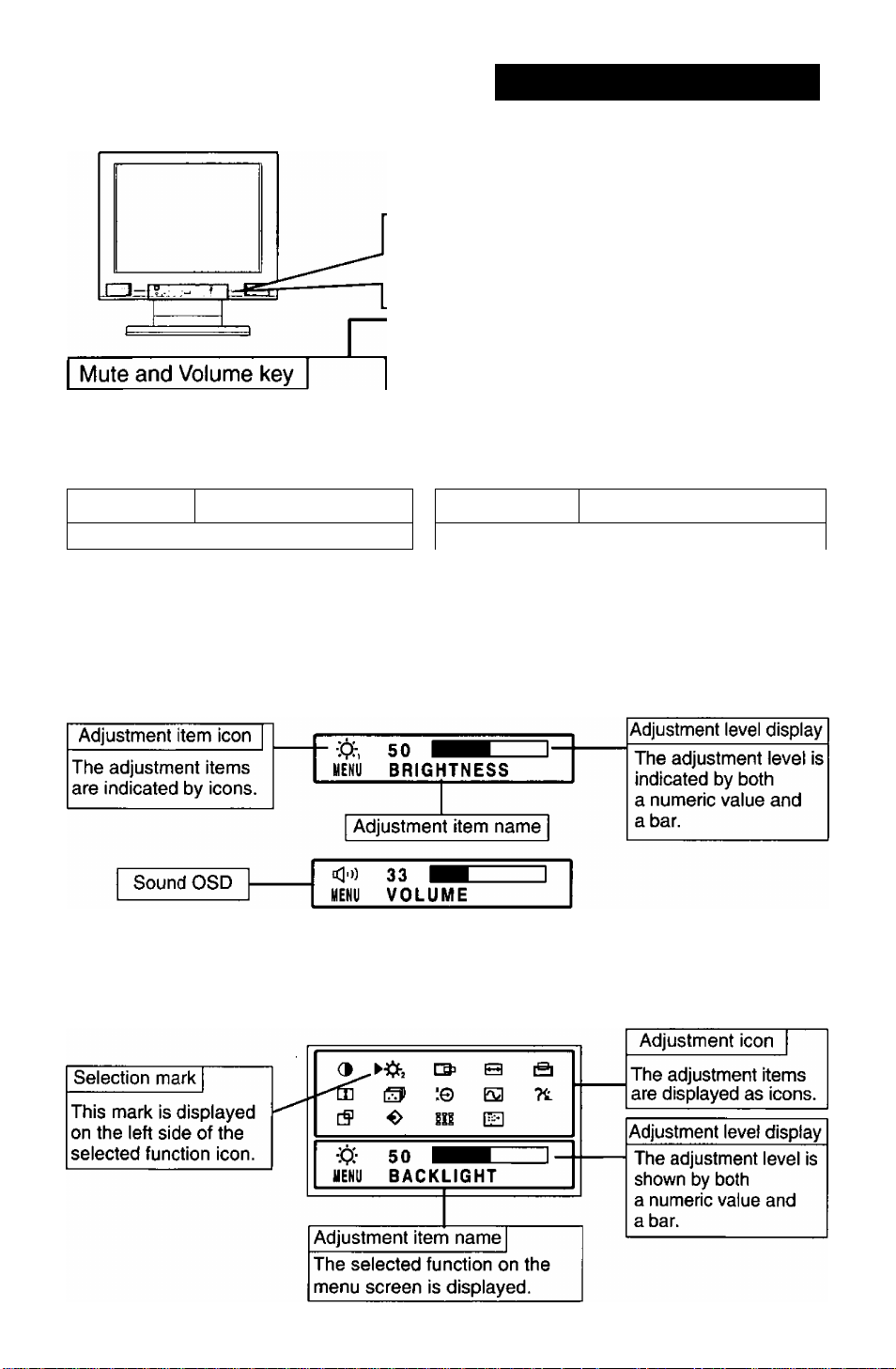
On-Screen Display (OSD)
The meaning of the items displayed in the
on-screen display are described below.
di cd- cd+
MENU
<1
>
O
<3
- and + keys
Adjusts the sound volume for the built-in
speakers and the headphone terminals.
These keys set the level of the adjustment
items. Direct operation: These keys perform
the screen display contrast and other
adjustments.
MENU key <1 and > keys
This key turns the menu screen on and off.
These keys select the adjustment items by shifting
Direct operation: These keys perform the screen
display brightness and other adjustments.
Direct Screen
There are three adjustments, contrast and brightness and mute and volume on the direct screen.
Menu Screen (When the resolution is set from 640 x 400 to 832 x 624)
The menu screen displays icons for the adjustment items of this unit.
However, brightness level 1 cannot be adjusted on the menu screen. (See Page 13
BRIGHTNESS (Black level).)
-11 -
Page 13
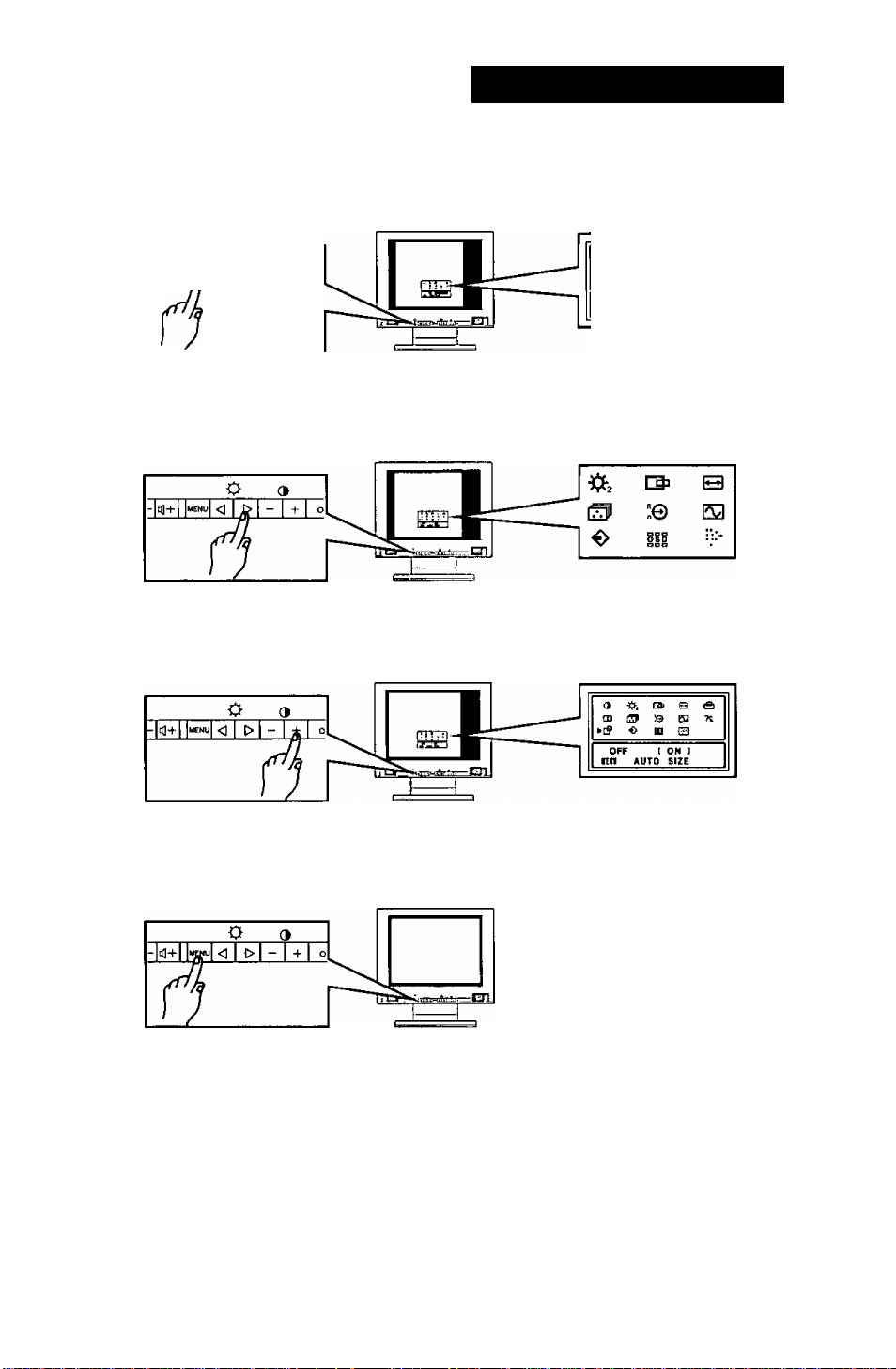
Operation Procedure
Auto size adjustment
1. Press the MENU key to display the main menu.
Refer to the figures below to perform
adjustments in the on-screen display.
O <1
2. Press the menu operation keys {<3 and t>) to shift the “ ► ” mark on the menu
screen to the auto size ((J) adjustment.
3. Use the menu operation key (+ key) to select ON. Auto size adjustment will start
operating.
»9 □» B a
m O n Tt
c? o m E3
4. If the settings on the screen are satisfactory, press the MENU key to record the
settings and exit.
5. If the settings on the screen are not satisfactory, manually re-adjust where necessary.
12 -
Page 14
Adjustments
Menu Screen
Ttie menu screen changes to two different screens according to the screen resolution.
The menu screen is displayed by the MENU key. The adjustment items of this unit are displayed as icons.
Each icon indicates an adjustment item shown in the figure.
When the resolution is 640 x 400 to 832 x 624
100
e?
o
100
üt> B
nt
:© EQ
m
IDI
c>
a
?t
□0 :q E3
[S lU
HEKU CONTRAST
When the resolution is 1024 x 768
►3
5
If
MENU CONTRAST
CONTRAST BACKLIGHT
V. SIZE
AUTO SIZE RECALL
CONTRAST
H. FINETUNE
AUTO SIZE RECALL
COLORTEMP
BACKLIGHT H. POSITION V. FINETUNE
COLOR TEMP
H. POSITION H. SIZE
VIDEO LEVEL
OSD POSmON
VIDEO LEVEL
OSD POSITION PICTURE
DISP. FREQ
PICTURE
DISP. FREQ
Adjustment Item Screen
d CONTRAST (White level)
Adjust the screen contrast. (Standard level = 100)
Press the MENU key to register the setting value.
Direct operation: Even if the menu screen does not appear, the contrast can be adjusted by
pressing the “+” or keys.
V. POSITION
UNGUAGE
V. POSITION
LANGUAGE
BRIGHTNESS (Black level)
Adjust the brightness (low gradation part: black level). (Standard level = 50)
Direct operation: Even if the menu screen does not appear, the contrast can be adjusted by
pressing the “0” or “[>” keys. Press the MENU key to register the setting value.
iCi-2 BACKLIGHT
Adjust the brightness of the backlight (Standard value = 100) by pressing the “+” or keys.
[Ql H. POSITION
The horizontal position of the image can be adjusted by pressing theor keys.
O H. SIZE ‘Adjustment when the resolution is set from 640 x 400 to 832 x 624
The horizontal amplitude of the image can be adjusted.
After aligning the left edge of the image by the horizontal position adjustment, change to the
horizontal size adjustment and perform the adjustment by pressing the or keys.
V. FINETUNE ‘Adjustment when the resolution is 1024 x 768
When the 1024 x 768 screen resolution is used, vertical stripes may be observed depending
on the desktop patterns or applications. If this occurs, perform the following adjustments.
Display a screen which has vertical stripes and align the right side of the screen by the
horizontal position adjustment, then change to the vertical stripe adjustment (V. FINETUNE)
and perform the adjustment using the “+" or keys.
-13-
Page 15

Adjustment Item Screen
iBl V. POSITION
The vertical position of the image can be adjusted by pressing the “+” or keys.
[U V. SIZE ‘Adjustment when the resolution is set from 640 x 400 to 832 x 624
The vertical size of the image can be adjusted.
After aligning the top edge of the image by the vertical position adjustment, change to the
vertical size adjustment and perform the adjustment by the “+" orkey.
However, the optimal adjustment cannot be performed in all operation modes.
^ H. FINETUNE ‘Adjustment when the resolution is 1024 x 768
When the 1024 x 768 screen resolution is used, characters may flicker or horizontal stripes
may appear depending on the desktop patterns or applications. If this occurs, perform the
following adjustments.
Display a screen which has horizontal stripes and align the bottom of the screen by the
vertical position adjustment, then change to the horizontal stripe adjustment (H. FINETUNE)
and perform the adjustment using the “+” or key.
There are more than two optimal points. One dot on the right or left may disappear
depending on the optimal point. If this occurs, shift to the other optimal point and
perform the horizontal position adjustment and the V. FINETUNE adjustment again.
COLOR TEMP
The white in the image can be selected from the three conditions, 1 (Normal color:}, 2 (9300K)
and 3 (User color: ADJ).
Use the “+” or key to select the user's preferred color from 1 (Normal color:}, 2 (9300K}
and 3 (User color: ADJ).
USER COLOR
The white in the video image can be adjusted to the user’s preferred color.
Select USER COLOR: [ < 3 > ADJ ] with the or keys on the COLOR TEMPERATURE
screen.
Select (ADJ) with the “+” key. Use the “0” or “t>” keys to select R (red), G (green) or B (blue).
Use the “+” and keys to adjust the color as desired.
Note: Make a note of the setting values before performing the adjustment because the recall
operation cannot be performed for the user color adjustment. The initial value is set to
normal color.
VIDEO LEVEL ADJ
:e
The video input signal level of your computer is adjusted automatically to 0.7 V -1.0 V.
Automatic adjustment is performed when ON Is selected with the “+” key.
Adjustment time is about 2 sec. - 3 sec.
Note) For this function to operate correctly, a white area about the size of the mouse
cursor is necessary. Correct adjustment is not possible without such a white area.
Q DISP. FREQ.
This displays the screen mode input on the LCD monitor.
The horizontal and vertical synchronization frequency are displayed.
The values for horizontal and vertical synchronization frequency of the video signal that is
currently input for the computer are displayed.
fH: There is an error of approximately 0.2 kHz max. for 30 kHz and 0.4 kHz max. for 61 kHz.
7^ LANGUAGE
Select one of the languages (German, French, English, Italian or Spanish) for the on-screen
display by pressing the “+” orkeys.
DEU: German FRA: French ENG: English
ITA : Italian ESP: Spanish
-14 -
Page 16

Adjustment Item Screen
AUTO SIZE
cf
The following adjustment items are automatically performed for the signal input trom the computer.
The horizontal position adjustment, horizontal size adjustment, vertical position adjustment,
vertical size adjustment, vertical fine adjustment (V. FINETUNE) and horizontal fine
adjustment (H. FINETUNE).
Always operate the unit after the computer has started.
Perform the adjustment after the Windows screen or other similar screen is
displayed in the entire screen.
Do not use this function when the VGA350 mode and DOS prompt mode are used
because the function will not operate correctly. Perform the adjustment manually.
^ RECALL
The initial settings (the settings when the display panel was shipped from the factory)
can be returned for each selection item.
The recall operation for the items to be reset is performed as follows.
The horizontal position adjustment, horizontal size adjustment, vertical position adjustment,
vertical size adjustment, horizontal fine adjustment (H. FINETUNE), vertical fine adjustment
(V. FINETUNE).
Press the “+” [YES] key to set an item and then press the MENU key.
Note: The recall screen display stops if there is no operation within approximately 30 seconds.
Ilg OSD
It is possible to adjust the position that the on-screen panel is to be displayed.
Moves each time the “+" or key is pressed.
POSITION
HFl PICTURE
Image quality can be set to four different modes to match the type of input by pressing the
or keys.
1) OFFICE MODE
Lowers the brightness when the monitor is to be used for an extended time.
2) STANDARD MODE
The factory setting.
3) DYNAMIC MODE
Emphasizes the outlines of images to make them sharper and easier to view.
4) ENTERTAINMENT MODE
Emphasizes the outlines of images even more than the Dynamic mode.
Note: The quality of text deteriorates when the Entertainment or Dynamic Mode is set.
VOLUME
This adjustment is performed directly from the front panel operation key.
C33]key is pressed, the volume is lowered. @Z)key is pressed, the volume is raised.
I Ikey is pressed, the volume is muted.
M6NiTbRSELF=-f^^
This function displays if the main unit is operating correctly.
Figure A or B is displayed if any of the five menu operation keys (MENU, <]; 0, -, +) are
pressed.
1) Figure A is displayed when the input synchronization signal exceeds the specified range.
• The frequency is displayed in red when fH or fV exceed the specified range.
2) Figure B is displayed when the power save mode is set. (This figure is only displayed in
the off state.)
3) Figure B is displayed when there is no input signal.
For example, this occurs when the computer is not connected or the computer power is off.
Figure A Figure B
SIGNAL ERROR
tH: 7B.9kHi fV; 74.6Hz
■mi
___________
NO SIGNAL
-15 -
Page 17
Power Management System
This monitor conforms to the VESA DPMS standard.
This function can reduce power consumption by the display unit.
The computer and video board being used must also conform to the VESA DPMS
standard.
* Consult the Operation Manuals for the hardware being used.
Modes change in response to input signals as indicated in the table below.
АРМ State Screen status
ON STATE
STAND-BY
SUSPEND without display
OFF STATE without display
with display
without display
Power
Indicator
color
green normal
yellow
yellow < 1 Swatts
yellow < Swatts
Power
consumption
< 1 Swatts
пешгп lime
—
<
4sec.
<
4sec. OFF ON
<
Ssec. OFF
Video
ON ON
OFF
* No USB peripherals
АРМ : Advanced Power Management
Procedure:
How to release the system from the power management function
1) Read the Operation Manuals for the hardware you are using.
2) Press one of the MENU-Э В— + keys on the front panel.
The NO SIGNAL screen appears, and the monitor side power management function is
released (only in OFF STATE).
Input signals
Horizontal sync.
OFF
OFF
Vertical sync.
ON
ON
OFF
OFF
Memories
This display has two types of memory to store the data sets that control the on-screen
image. The first type of memory is the Preset Memory which is set by the factory. The
second type is the User Memory which is set by the user. Both memories store the
Horizontal Size, Vertical Size, Horizontal Position, Vertical Position, V. finetune,
H. finetune. Picture and Video signal level adjustments of the displayed image.
Preset Memory
There are 15 reservation timing that are set by the factory. The preset timing will automatically size and center
the image with video boards which use these timing. Please see page 17 tor Timing Specifications.
User Memory
• There are 16 memory locations that allow for user timing. The image size and position are adjusted by the
user. Please see page 17 for recommended timing that the display supports.
• If the User Memory is completely full, and a new set of data is saved, the oldest data set in the User Memory
will be deleted.
• When the user timing is input, the Total line, Horizontal frequencies and sync polarities of the signal are
compared with the previous data stored in memory. The input signal will be stored as a new data set if one of
its parameters is different from the previous stored one.
• The new input signal must have a frequency difference greater than that shown in the table below or a
different sync, polarity from that already stored. If the new timing data includes frequency changes greater
than those shown in the table below or sync, polarity changes, a new user memory setting will be stored. If
the frequency difference is smaller than that of the chart and the sync, polarities are the same, the existing
settings will be retained.
Horizontal frequency
Low 30 kHz ± 0.2 kHz
to
Hi 61 kHz ± 0.4 kHz
Please note if the timing does not meet the display specifications, the size and position adjustment may not
appear as desired. Be sure the horizontal and vertical timing are within the monitor specification range.
See page 17 for Timing Specifications. See pages 17 and 18 for preset, reservation and recommended timing.
Total line
± 4 Line
- 16 -
Page 18
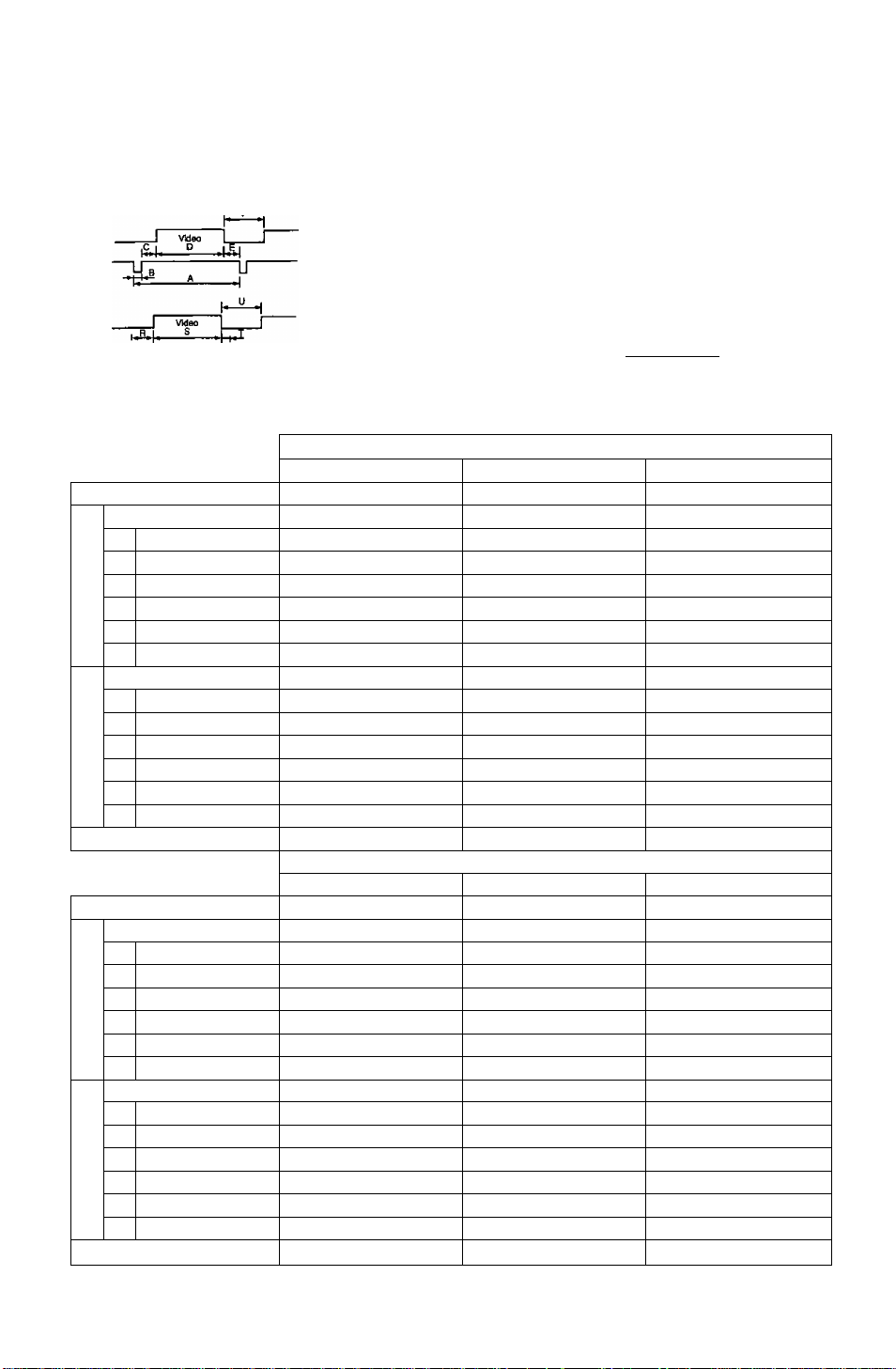
Timing Specifications
Non-interlaced only
Separate Sync.
F
H/V Composite Sync.
I Video I
-------B-------
uinnnn
__
^ L_Q
)^Nn^rL_r
_p
-------------------
VGA 640 x 480 @ 60Hz
DOT CLOCK
fH
A H-Period
S
c
s
•c
o
X
H-Blanking
F
B H-Sync width
H-Back porch
C
D H-Active
H-Front porch
E
fV
P V-Period
u
5
>
V-Sync width
0
R V-Back porch
V-Active
S
V-Blanking
U
«
T V-Front porch
Sync polarity (H / V)
25.1745 MHz
31.4681 kHz
31.778 us(800) Dots
6.355 us{160) Dots
3.813 us( 96) Dots
1.907 us( 48) Dots
25.423 us(640) Dots
0.636 us( 16) Dots
59.9393 Hz
16.684 ms(525) Lines
1.430 ms{ 45) Lines
0.064 ms{ 2) Lines
1,049 ms( 33) Lines
15.254 ms(480) Lines
0.318 ms( 10) Lines
Negative / Negative
VESA 640 x 480 @72 Hz
DOT CLOCK
fH
A
H-Period
s
F H-Btanking
C
o
N
B H-Sync width
•c
o
X
H-Back porch
C
D H-Active
H-Front porch
E
fV
P V-Pehod
U V-Blanking
■ 5
0
c
>
V-Sync width
0
R V-Back porch
S V-Active
T
V-Front porch
Sync polarity (H / V)
Note: All modes are Non-Interlaced.
* Factory Reservation timing have approximate size & centering,
** Requires the use of Optional Mac Adapter UNIMAC-82D.
31.5000 MHz
37.861 kHz
26.413 us(832) Dots 26.667 us(840) Dots
6.096 us(192) Dots
1.270 us{ 40) Dots
4.063 us( 128) Dots
20.317 us{640) Dots 20.317 us(640) Dots
0.762 us( 24) Dots 0.508 us( 16) Dots
72.8088 Hz
13.735 ms{520) Lines
1.057 ms( 40) Lines
0.079 ms( 3) Lines
0.740 ms( 28) Lines 0.427 ms( 16) Lines
12.678 ms(480) Lines
0.238 ms( 9) Lines
Negative / Negative Negative / Negative
- 17 -
Sync, on Green
-------
U"
J
Reservation timing*
VGA 640 X 400 @ 70 HzMac(l3‘) 640 x 480 @67Hz"
25.1745 MHz
31.4681 kHz
31.778 us(800) Dots
6.355 us(160) Dots
3.813 us( 96) Dots
1.907 us( 48) Dots
25.423 us{640) Dots
0.636 us( 16) Dots
70.0849 Hz 66.6689 Hz
14.268 ms(449) Lines
1.557 ms{ 49) Lines
0.064 ms( 2) Lines
1.112 ms{ 35) Lines
12.711 ms(400) Lines
0.381 ms{ 12) Lines
Negative / Positive
Reservation timing*
VESA 640 X 480 @75Hz
31.5000 MHz
37.500 kHz
6.350 us(200) Dots
2.032 us( 64) Dots
3.810 us(120) Dots
75.000 Hz
13.333 ms{500) Lines
0.533 ms( 20) Lines
0.080 ms( 3) Lines
12.800 ms(480) Lines
0.027 ms( 1) Line
-uJ
4-e4
illnm_nnntt"'#rv^
JUB |.■Q„.|.R,1^ s
30.2410 MHz
35.0012 kHz
28.570 us( 864) Dots
7.407 us( 224) Dots
2.083 us( 63) Dots
3.241 us( 98) Dots
21.163 us( 640) Dots
2.083 us( 63) Dots
15.000 ms( 525) Lines
1.286 ms( 45) Lines
0.086 ms( 3) Lines
1.114 ms( 39) Lines
13.714 ms{ 480) Lines
0.086 ms{ 3) Lines
Negative / Negative
VESA 800x600 @56 Hz
36.0000 MHz
35.1562 kHz
28.444 us{1024) Dots
6.222 us{ 224) Dots
2.000 us( 72) Dots
3.556 us( 128) Dots
22.222 us( 800) Dots
0.667 us{ 24) Dots
56.250 Hz
17.778 ms{ 625) Lines
0.711 ms( 25) Lines
0.057 ms( 2) Lines
0.626 ms( 22) Lines
17.067 ms( 600) Lines
0.028 ms( 1) Line
Positive / Positive
1-^
Page 19
Non-interlaced only
VESA 800x600 @60 Hz
DOT CLOCK
fH
A H-Period
H-Blanking
H-Sync width
H-Back porch
H-Active
D
H-Front porch 1.000 us( 40) Dots
fV
P V-Period
U V-Blanking
V-Sync width 0.106 nns( 4) Lines
V-Back porch 0.607 ms( 23) Lines 0.478 ms( 23) Lines 0.448 ms( 21) Lines
V-Active 15.840 ms( 600) Lines 12.480 nns( 600) Lines 12.800 ms( 600) Lines
V-Front porch
Sync polarity (HA/) Positive / Positive
DOT CLOCK
fH
A H-Period
H-Blanking
H-Sync width
H-Back porch
H-Active
H-Front porch
fV
P V-Period
V-Blanking
U
V-Sync width
V-Back porch
V-Active
V-Front porch
Sync polarity (H / V)
DOT CLOCK
fH
A H-Period
H-Blanking
H-Sync width
H-Back porch
H-Active
E H-Front porch
fV
P V-Period
V-Blanking
U
V-Sync width
V-Back porch 0.501 ms{ 29) Lines 0.466 ms( 28) Lines
V-Active
T V-Front porch
Sync polarity {H / V) Negative / Negative
Note: All modes are Non-Interlaced.
* Factory Reservation timing have approximate size & centering.
•• Requires the use of Optionai Mac Adapter UNIMAC-82D, _ i g
40.0000 MHz
37.8788 kHz
26.400 us(1056) Dots 20.800 us(1040) Dots 21.333 us(1056) Dots
6.400 us( 256) Dots
3.200 us( 128) Dots
2.200 us( 88) Dots
20.000 us( 800) Dots
60.3165 Hz
16.579 ms( 628) Lines
0.739 ms( 28) Lines
0.026 ms( 1) Line 0.770 ms( 37) Lines 0.021 ms( 1) Line
Mac{16‘)832 x 624 @ 75Hz”
57.2832 MHz
49.7250 kHz 48.3631 kHz
20.111 us(1152) Dots 20.677 us(1344) Dots
5.587 us( 320) Dots
1.117 us( 64) Dots
3.910 us( 224) Dots
14.524 us( 832) Dots 15.754 us(1024) Dots
0.559 us( 32) Dots
74.5502 Hz
13.414 ms( 667) Lines
0.865 ms( 43) Lines 0.786 ms( 38) Lines
0.060 ms( 3) Lines 0.124 ms( 6) Lines
0.784 ms( 39) Lines
12.549 ms( 624) Lines 15.880 ms( 768) Lines
0.020 ms( 1) Line 0.062 ms( 3) Lines
Negative / Negative
VESA 1024 x 768 @72 Hz
75.0000 MHz
57.8703 kHz
17.280 us(1296) Dots
3.627 us( 272) Dots 3.657 us( 288) Dots
1.920 us( 144) Dots
1.387 us( 104) Dots
13.653 us(1024) Dots
0.320 us( 24) Dots
71.7978 Hz
13.928 ms( 806) Lines
0.657 ms{ 38) Lines
0.104 ms{ 6) Lines 0.050 ms{ 3) Lines
13.271 ms{768) Lines 12.795 ms( 768) Lines
0.052 ms{ 3) Lines
Reservation timing
VESA 800 x 600 @72 Hz
50.0000 , MHz
48.0769 kHz
4.800 us( 240) Dots
2.400 us( 120) Dots
1.280 us( 64) Dots
VESA 800 X 600 @ 75Hz
49.5000 MHz
46.875 kHz
5.171 us{ 256) Dots
1.616 us( 80) Dots
3.232 us( 160) Dots
16.000 us( 800) Dots 16.162 us( 800) Dots
1.120 us( 56) Dots 0.323 us( 16) Dots
72.1876 Hz
75.0000 Hz
13.853 ms( 666) Lines 13.333 ms( 625) Lines
1.373 ms( 66) Lines 0.533 ms( 25) Lines
0.125 ms( 6) Lines 0.064 ms( 3) Lines
Positive / Positive
Reservation timing* *
VESA 1024 x 768 @60 Hz VESA 1024 X768 @ 70 Hz
65.0000 MHz
Positive / Positive
••
75.0000 MHz
56.4759 kHz
17.707 us(1328) Dots
4.923 us{ 320) Dots 4.054 us{ 304) Dots
2.092 us( 136) Dots 1.813 us( 136) Dots
2.462 us{ 160) Dots 1.920 us{ 144) Dots
13.653 us(1024) Dots
0.369 us( 24) Dots 0.320 us( 24) Dots
60.0038 Hz
70.0694 Hz
16.666 ms( 806) Lines 14.272 ms( 806) Lines
0.673 ms( 38) Lines
0.106 ms( 6) Lines
0.600 ms( 29) Lines
0.513 ms( 29) Lines
13.599 ms( 768) Lines
0.053 ms( 3) Lines
Negative / Negative Negative / Negative
Reservation timing
VESA 1024 x 768 @75 Hz
78.7500 MHz
60.0229 kHz
Mac (1901024 x 768 075 Hz"
80.0000 MHz
60.241 kHz
16.660 us(1312) Dots 16.600 us(1328) Dots
3.800 us( 304) Dots
1.219 us( 96) Dots
2.235 us( 176) Dots
13.003 us{1024) Dots
0.203 us{ 16) Dots
75.0286 Hz
13.328 ms( 800) Lines
0.533 ms{ 32) Lines
1.200 us( 96) Dots
2.200 us( 176) Dots
12.800 us(1024) Dots
0.400 us( 32) Dots
74.927 Hz
13.346 ms( 804) Lines
0.597 ms( 36) Lines
0.049 ms( 3) Lines
0.498 ms( 30) Lines
12.749 ms( 768) Lines
0.017 ms{ 1) Line
Positive / Positive
0.049 ms( 3) Lines
Negative / Negative
Page 20

Trouble Shooting
AA
For safety, please observe the following points.
• When trouble occurs, disconnect the power plug
immediately and contact your dealer.
If smoke comes out of this unit or a bad odor or strange noise comes out, continuing
to use the unit can cause a fire or electrical shock. Turn the power OFF immediately,
unplug the power cord from the outlet and contact your dealer.
• Absolutely do not attempt to remove the rear cover.
There are parts at hiqh voltage inside, so touching them can cause an electrical
shock. Leave inspection, adjustment and cleaning of the interior to your dealer.
• Do not allow anything inside the casing.
If liquid or a foreign object should get inside accidentally, immediately turn the power
OFF, unplug the power cord from the outlet and contact your dealer. Continuing to
use the unit can cause a fire, electrical shock or breakdown of the unit.
If trouble occurs with the display unit, perform the following checks and take the indicated action; if the trouble persists, please consult with your dealer.
Symptom Check Action
The LED Power Indicator
does not light (is dark).
There is no image and
LED Power Indicator is
yellow.
The LED Power Indicator
does not go off (dark).
The image is too large or
too small. It is displaced
from the correct position.
Part of the image is
missing.
The color of part of the
screen is changed.
There are vertical or
horizontal stripes in the
image.
There is an after-image in
the image.
Characters cannot be
seen clearly even after an
adjustment is performed.
M
The outlines of text are
sharp.
M
AC Power cord / plug
Power Switch (Right Side)
Signal cable
Computer (The power saving
function might have operated.)
Contrast, Brightness and
Backlight adjustments.
Power Switch
is not the mode registered?
Is the mode guaranteed?
Perform theV. FINETUNE
(Vertical stripe), H. FINETUNE
(Horizontal stripe) adjustments
(In the1024 X 768 mode).
Liquid Crystal panel
H. FINETUNE (Horizontal
stripe) adjustments
Does the video clock frequency
of the image signal exceed the
standard level (80 MHz)?
Has the Office mode been set?
Is the video levei correctly
adjusted?
Is the brightness or contrast
adjustment turned all the way
down?
Has the Dynamic or
Entertainment mode been set?
Plug the AC power cord into a grounded outlet
correctly.
Press the Power Switch.
Connect the Signal Cable correctly.
Release the power saving function
(See "Procedure” Page 16).
Adjust the Contrast, Brightness and Backlight
correctly (See Page 13).
Press the power switch one more time (Right Side)
Use an on-screen function to perform the desired
settings.
Read the computer operation manual and change
the display mode to obtain the specified mode.
When the 1024 x 768 mode is set, perform the
adjustment so the stripe patterns are not
conspicuous.
Change the desktop pattern in modes other than
1024 X 768.
If the same image is displayed on the LCD for a
long period of time, a phenomenon called "burnin“ may occur where slight traces of the burned-in
screen pattern can still be observed when other
screen patterns are displayed.
Do not operate the display for approximately one
day and do not turn the power on.
Perform the necessary adjustment untii the
characters dispiayed on the screen do not fiicker.
Lower the vertical frequency of the image signal to
set the video clock frequency to level below the
standard level (80 MHz).
Set the Standard mode.
Check the video signal level from the computer
and adjust it in the correct direction.
Adjust the brightness, backlight and contrast.
(Refer to the computer operation manual of the
computer that is used for further details.)
Set the Standard mode.
-19 -
Page 21
Symptom Check Action
The image is too dark.
The image scrolls
continuously.
The display color is
abnormal.
The screen size and
position do not change.
The front panel keys fail
to operate.
The sound is not correct.
The headphones do not
operate.
The USB device does not
operate.
SELF-TEST function
Signal cable
Signal cable Connect the signal cable correctly.
Is the input synchronization
signal within the operating
range?
Are 2 or more buttons being
operated at the same time?
AUDIO cable
Computer sound level
Headphone jack
USB cable
USB hub power cable
Press the MENU key to check the SELF-TEST
screen.
Is either one of the numeric values for fH or fV
displayed in red?
The input signal frequency exceeds the range of
the security range of this unit.
Read the operation manual of the computer and
change the display mode.
Check the video output mode from the computer,
and select a mode within the LCD monitor
operating range. (For details, please read the
operation manual of the hardware you are using.)
Operate only one key at a time.
Connect the AUDIO cable correctly. Is the sound
level from the computer restricted?
Please refer to the operation manual for the
hardware you are using for the details.
Connect the headphone jack correctly.
Connect the USB cable correctly.
For details, read the operation manual of the
USB device you are using.
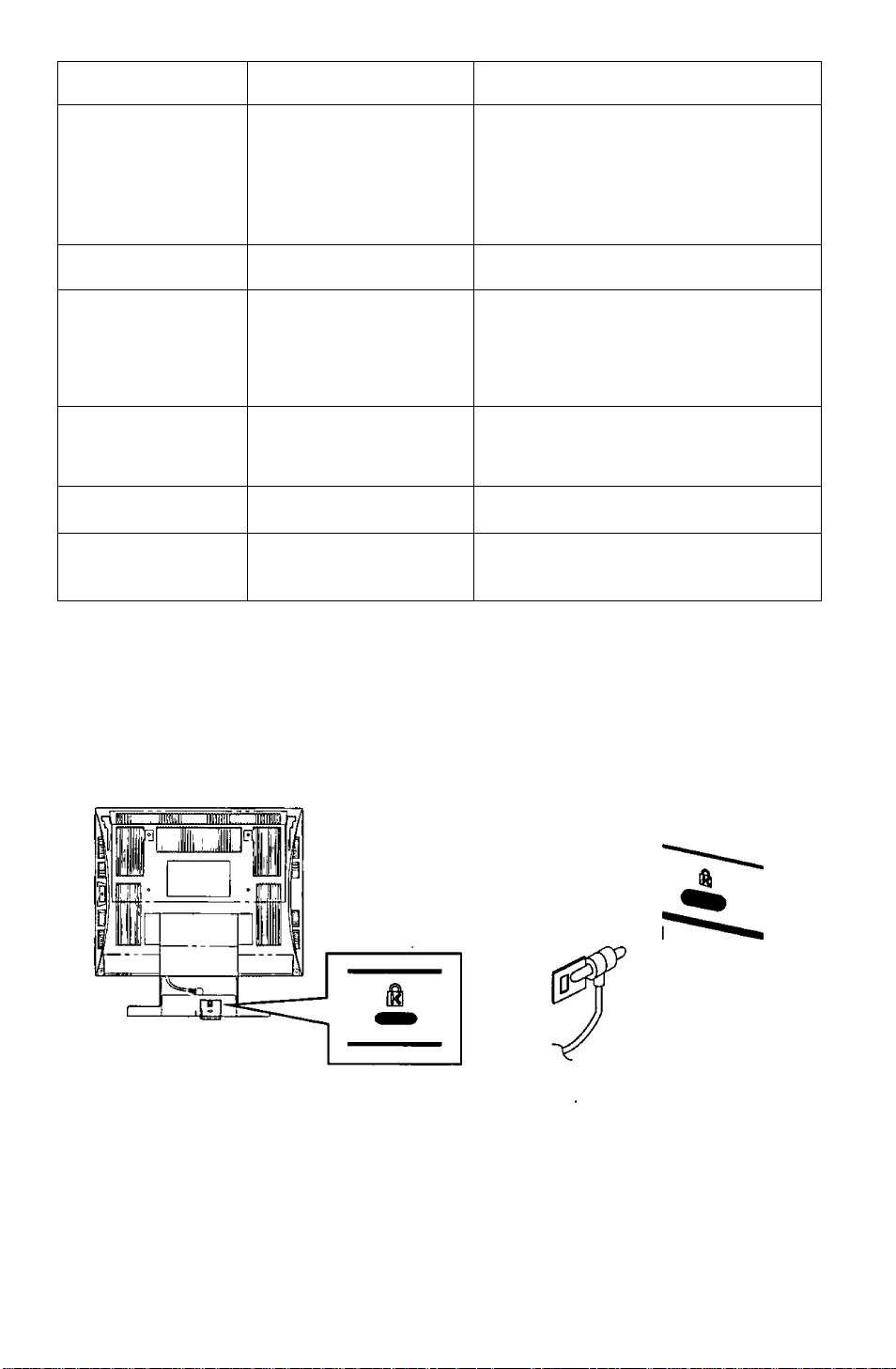
Security Port
A security cable can be installed to prevent theft of the LCD monitor base.
A wire cable manufactured by Kensington can be connected to the security port on the
rear panel of the main unit.
For details, please refer to the Kensington instruction manual
< lnquiries>
Kensington
2855 Campus Drive
San Mateo, CA USA 94403
800-535-4242, x3348
Intri: 415-572-2700, x3348
Fax: 415-572-9675
-20 -
Page 22

Technical Support (USA Only)
If you have read the Operating Instructions
and tried the troubleshooting procedures and
are still having difficulty, please contact the
dealer from whom the unit was purchased.
You may also call the end user Technical
Support telephone number which is
operational twenty four (24) hours a day
seven days a week.
Apple (Apple Computers)
AUTO SIZE
BACKLIGHT
.................................
................................
............
BRIGHTNESS.............................
COLOR TEMP.............................
CONTRAST.................................
CSA
.............................................
DDC
............................................
Dimensions
DISP.FREQ
DPMS
Energy Star®
H. FINETUNE
Horizontal frequency
H. POSITION
.................................
.................................
..........................................
.................................
.............................
...................
..............................
H. SIZE........................................
IBM
..............................................
LANGUAGE
Macintosh
................................
....................................
MONITOR SELF-TEST...............
To contact the Technical Support Group call:
1-800-726-2797 (24 Hours a day)
To locate the Nearest Authorized Panasonic Service
Center call:
1-800-726-2797 (24 Hours a day)
To obtain Operating Instructions and Service Manuals call:
Phone: 1-800-833-9626 or 1-253-395-7343
Fax : 1-800-237-9080
(6:00 AM to 4:30 PM Pacific Time)
To locate the Nearest Sales Dealer call:
1-800-742-8086 (24 Hours a day)
To get the latest Windows 95/98 Panasonic Monitor.
INF files call:
PanaTech BBS (201) 863-7845 (24 Hours a day)
You may also wish to see our world wide web pages at:
http://www.panasonic.com/alive
Index
.............
...........
...........
...........
...........
...........
.............
.............
...........
...........
.............
.............
...........
.............
...........
...........
..................
...........
.............
...........
7
On-Screen Display.........................
15
13
13
14
13
OSD POSITION.............................
Operating frequency range
PICTURE
Pin assignments
.......................................
............................
Power management system
RECALL.........................................
6
............
..........
5 Specifications.................................
10
Tilt range
14 Trouble shooting
5 UL
........................................
............................
..................................................
2 USB................................................
14
13
USER COLOR
V. FINETUNE
6
Vertical frequency
13 V. POSITION
7 V. SIZE...........................................
14 VIDEO LEVEL ADJ
...............................
................................
..........................
.................................
.......................
7 VOLUME........................................
15
........11
........15
..........
........15
........10
........16
........15
..........
.......
10
........19
..........
..........
........14
........13
..........
........14
........14
........14
........15
6
6
6
9
6
-21 -
Page 23

-22 -
Page 24

NOTICE IMPORTANTE CONCERNANT LE CHOIX DU CORDON D’ALIMENTATION
Le cordon d'alimentation conçu pour cette unité a été conditionné dans un emballage distinct et il a été choisi en
ionction du pays de destination. Son utilisation vise à vous prévenir de toute décharge électrique. Si vous devez
remplacer le cordon initial, veuillez suivre les informations d-dessous mentionnées.
Le receptade femelle du cordon doit satisfaire aux normes CEE-22 et comporter les caractéristiques présentées au
Schéma 1.
Etas-Unis et Canada:
Aux Etats-Unis ainsi qu'au Canada, la prise mâle est de type NEMA 5-15 (Schéma 2): elle est mentionnée dans la liste
UL et porte la mention CSA. En ce qui concerne les unités qui sont placées sur une table ou sur un bureau, il est
possible d’utiliser des cordons de type SVT ou SJT. Quant aux unités qui sont placées à même le sol, seuls des
cordons de type SJT peuvent être utilisés. Le choix du cordon doit s’effectuer en fonction de l’ampérage de votre unité.
Veuillez consulter te Tableau A suivant les critères de selection des cordons d’alimentation utilisés aux Etats-Unis et au
Canada. (Le jeu de cordon est marqué du type du cordon.)
Pays européens:
En Europe, vous devez utiliser des cordon appropriés aux prises de votre pays. Les cordons doivent être de
marque 4 HAR ^ et celle-ci doit apparaître sur la gaine plastique externe ou sur la partie isolante d'un des con
ducteurs internes.
Si vous avez des questions concernant le bon cordon à utiliser, vous êtes priés de consulter le concessionnaire chez qui
vous avez acheté votre appareil.
Tableau A
Type de cordon Taille des conducteurs dans le cordon
SJT
SVT
Schéma 1 Schéma 2
18AWG
16AWG 12Amps
14AWG 12Amps
18AWG
17AWG
Ampérage maximum de l’unité
10Amps
lOAmps
12Amps
Conditions imposées par la commission fédérale des communications
L’appareil a été testé et jugé conforme aux limites des appareils numériques de classe B, aux termes de
la section 15 de la Réglementation FCC. Ces limites ont pour but d’assurer une protection raisonnable
contre les interférences parasites dans une installation résidentielle. Cet appareil engendre, utilise et peut
émettre une énergie radioélectrique et, s’il n’est pas installé et utilisé en stricte conformité avec ces
instructions, il peut provoquer des interférences parasites dans les liaisons radiophoniques. Ceci ne
garantit pas pour autant qu’une installation particulière n’émettra aucune interférence. Si l’appareil
engendre des interférences parasites avec la réception radio ou télévision, ce qui pourra être déterminé et
éteignant puis en rallumant l’appareil, il est conseillé à l'utilisateur d’essayer de corriger les interférences
en prenant l’une des mesures ci-dessous:
- Modifer l'orientation ou changer l’emplacement de l’antenne de réception.
- Eloigner davantage l’appareil du récepteur.
- Brancher l’appareil dans une prise d’un circuit différent de celui auquelle le récepteur est raccordé.
- Demander l'aide de son agent ou d’un technicien radio / télévision qualifié.
Avertissement FCC:
Pour garantir une conformité constante à la Réglementation FCC, l'utilisateur devra utiliser un cordon
d'alimentation avec mise à la terre, et le câble d’interface vidéo blindé livré avec l’appareil, avec tiges
de ferrite incorporées. Par ailleurs, toute transformation ou modification non autorisée de l’appareil
retirera à l'utilisateur le droit d’utiliser ce moniteur vidéo.
-23 -
Page 25

Conformité CE
Cet appareil est conforme aux exigences de la directive CEE 89 / 336 / CEE modifiée par la
directive 92/31 / CEE et par l'Article 5 de la directive 93 / 68 / CEE relative à la “compatibilité
C€
Interférence électramagnétiqije
Décharge électrostatique
Emission de radiofréquence
Salve rapide transitoire
Harmoréques de ligne
#1 : Satisfait aux normes sans problème de performance ni de fiabilité.
#2 : Des effets peuvent apparaître temporairement sur l'écran, mais il n’y aura pas de problème de fiabilité.
#3 : Risque de panne.
#4 : Si l’on utilise un câble de signal autre que celui spécifié, il pourra provoquer une interruption d’onde
Pour garantir une conformité CE constante, l’usager devra utiliser le câble de signal vidéo blindé de 1,5
m avec tiges de ferrite aux deux extrémités du câble, qui est livré avec l'appareil.
Manipuler conformément aux instructions.
EMI : Perturbation électromagnétique ESD : Décharge électrostatique
RF : Rediofréquence F/B ; Salve rapide
électromagnétique, et de la directive 73 / 23 / CEE modifiée par l’Article 13 de la directive
93 / 68 / CEE relative à la “Sécurité”.
Article exigé
électromagnétique dans les périphériques.
Par rapport aux valeurs standard Par rapport à ceux dépassant les valeurs standardRemarques
#1 #4
#2 #3
#1 #3
#1 #3
#1
~ —
Ч ' y
Уч
/
_____
\
En sa qualité de partenaire d’ENEROv Star®, Panasonic Computer Peripheral
Company a jugé que ce produit respectait les directives de rendement énergétique
d’ENERGY Star®.
Notice pour rallemagne
REMARQUE:
• Pour des raisons d'ergonomie, il est recommandé de ne pas utiliser la couleur de base bleue sur un fond
sombre. Cela resque de produire une insuffisance de contraste qui pourrait fatiguer les yeux.
Allemand
HINWEIS:
• Aus ergonomischen Gründen wird empfohlen, die Grundfarbe Blau nicht auf dunklem Untergrund zu
verwenden (schlechte Erkennbarkeit, Augenbelastung bei zu geringem Zeichenkontrast wäre die Folge).
Notice pour le Japon
Cet appareil est classé dans la catégorie B, selon les normes définies par le Conseil
de contrôle volontaire sur les interférences (CCVI) de l'équipement pour la
technologie informatique. Utilisé à proximité d’un récepteur de radio ou de télévision
dans les conditions d’un domicile privé, il peut être à l’origine d’interférences des
ondes radio. Installer et utiliser l’appareil conformément aux instructions de la notice
d’emploi.
Japonais
(VCCI)
TIE U иж и =& с г T ¿F Ио
-24 -
Page 26

Danger
Pour éviter tout risque de choc électrique grave ou de mort, ne pas retirer les
couvercles (ni le dos) du moniteur. L’appareil ne renferment aucune pièce qui soit
réparabie par l’utilisateur. Confier toute réparation à un personnel qualifié.
A\ A\ [Avertissements
Pour éviter tout risque de choc électrique et de feu:
Ne pas utiliser de rallonge, mais toujours brancher le cordon d’alimentation secteur du
moniteur directement dans une prise correctement polarisée et mise à la terre.
Ne jamais rien poser sur, le cordon d’alimentation secteur ni le cordon d’alimentation
CC, veiller à ne pas trop plier les cordons, et ne rien faire qui puisse affecter l’intégrité
des cordons. Toujours débrancher le cordon d’alimentation secteur de la prise en tirant
sur la prise et non sur le cordon proprement dit.
Ne pas poser de récipient renfermant des liquides (même un chiffon humidité de liquide)
sur le moniteur car la pénétration de liquides pourrait être source de danger électrique.
Ne pas exposer le moniteur à la pluie ou à l’humidité.
Ne pas installer le moniteur sans respecter le jeu spécifié (voir les Précautions,
1 Installation, Page 26). Ne pas boucher les orifices de ventilation. Ne pas insérer d’objets dans les orifices de ventilation.
Renseignements à relever par le client
En cas de vol ou de perte, il est important de conserver le No. de série dans un dossier afin de
permettre l’identification. Noter le numéro de série dans l'espace prévu et conserver ce manuel à
titre de consignation permanente de l'achat. Il aidera à identifier l'appareil en cas de vol ou de perte.
Numéro de modèle : TX-D5L31F / TX-D5L31FG
Numéro de série
Table des matières
NOTICE IMPORTANTE CONCERNANT LE CHOIX DU CORDON
D’ALIMENTATION..........................................................................................................23
Conditions imposées par la commission federale des communications.........................23
Conformité CE.................................................................................................................24
Notice pour l’allemagne...................................................................................................24
Notice pour le japon........................................................................................................24
Danger.............................................................................................................................25
Avertissements................................................................................................................25
Renseignements à relever par le client...........................................................................25
Table des matières..........................................................................................................25
Précautions 1) Installation...............................................................................................26
Précautions 2) Utilisation................................................................................................26
Précautions 3) Soin du produit........................................................................................26
Caractéristiques..............................................................................................................27
Fiche technique...............................................................................................................28
Installation.......................................................................................................................29
Raccordement d'un périphérarique USB........................................................................31
Affectation des broches...................................................................................................32
Aspect extérieur..............................................................................................................32
Affichage sur écran (OSD)..............................................................................................33
Procédure de fonctionnement.........................................................................................34
Réglages.........................................................................................................................35
Système de gestion d’énergie.........................................................................................38
Mémoire.......................................................................................................................... 38
Spécifications de synchronisation...................................................................................39
En cas d’anomalie..........................................................................................................41
Port de sécurité...............................................................................................................42
Assistance technique......................................................................................................43
Index............................................................................................................................... 43
TOUS LES NOMS DE PRODUIT / MARQUE SONT DES MARQUES DE FABRIQUE OU DES MARQUES DÉPOSÉES DES DÉTENTEURS RESPECTIFS.
© 1998 MATSUSHITA ELECTRIC INDUSTRIAL Co., Ltd.
-25 -
Page 27

Mesures de précaution
1) Installation
• Installer le moniteur dans un endroit suffisamment aéré. Eviter toute exposition en plein
soleil et à des sources de chaleur (appareil de chauffage, etc.). La chaleur aurait des
conséquences néfastes sur les coffrets et sur les pièces internes.
• Placer l’écran de façon que les orifices du coffret ne soient pas obstrués pendant le
fonctionnement.
• Eloigner l’écran des cuisines, salles de bains, lave-linge et autres sources d’eau, de
vapeur et d’humidité.
• Pour utiliser l’écran en toute sécurité, utiliser exclusivement le cordon d’alimentation
fourni. Le cordon d’alimentation secteur devra être branché dans une prise secteur
correctement mise à la terre et polarisée. Le cordon d’alimentation secteur fourni
convient pour un usage aux Etats-Unis (UL) et au Canada (CSA) avec l’écran. Pour les
autres pays, bien utiliser un cordon qui respecte les normes de sécurité du pays en
question.
• Placer le cordon d’alimentation dans un endroit où il ne subira pas de contrainte.
• Utiliser exclusivement les accessoires Panasonic fournis, ou des équivalents exacts.
2) Utilisation
• Ne pas tirer sur le cordon d’alimentation secteur, le cordon d’alimentation CC ni le câble
de signal VGA car cela pourrait endommager l’écran (le moniteur), faire tomber
l’appareil et provoquer des blessures.
• Anomalies de réception
S’il y a un téléviseur ou un autre écran à proximité, éloigner l’écran le plus possible. Les
interférences mutuelles pourraient provoquer une distorsion des images ou des
parasites.
• Un contact prolongé avec des produits en caoutchouc ou en vinyle risque de tacher le
coffret.
• Lors du transport, protéger le moniteur contre les chocs. Faire attention à l’écran à
cristaux liquides à matrice active (AM-LCD).
• Ne rien poser sur le moniteur.
• Toujours faire attention au cordon d’alimentation.
Ne rien poser sur le cordon d’alimentation. Ne pas tenter de le rallonger, de le
raccourcir ni d’y faire des noeuds.
3) Soin du produit
• Avant de nettoyer l’écran, débrancher le cordon d’alimentation CC et le câble de signal
VGA de l’écran.
• Nettoyer l’extérieur du moniteur ou la surface de l’écran AM-LCD à l’aide d’un chiffon
doux et sec. Si le moniteur ou la surface de l’écran AM-LCD sont très sales, humecter
un chiffon doux et propre de détergent neutre (par exemple un produit à vaisselle) et
d’eau, bien te tordre de façon qu’il soit presque sec, essuyer le moniteur ou la surface
de l’écran AM-LCD avec, puis les essuyer à nouveau avec un chiffon propre et sec.
• Ne pas frotter ni heurter l’écran AM-LCD avec quelque chose de dur ou de cassant car
cela pourrait le rayer, l’abîmer ou l’endommager irrémédiablement.
• Les chiffons chimiques ou chiffons à cire peuvent endommager l’appareil et provoquer
un enlèvement de la peinture.
-26 -
Page 28

Caractéristiques
1) Panneau d’affichage à cristaux liquides à matrice active’^ AM-LCD
• L’écran de 15 pouces (surface utile de visionnement 15,0 pouces / 38,1 cm) de 1,024 x 768 pixels
(pas de pixel 0,297 mm) AM-LCD à revêtement dur anti-éblouissement permet une faible réflexion,
une résolution et un contraste élevés, la suppression de l’électricité statique, une vraie couleur
haute résolution (16,19 millions de couleurs) et un fort contraste.
2) Commandes numériques conviviales avec menu sur écran
• Les réglages numériques de la luminosité et du contraste sont accessibles directement sur le
panneau avant.
• Les menus sur écran sont disponibles en 5 langues : allemand, français, anglais, espagnol et
italien.
• Les réglages personnalisés s’effectuent rapidement et en toute facilité grâce au menu sur écran à
base d'icônes qui utilise cinq touches douces sur le panneau avant.
• Le menu principal à base d’icônes permet de faire défiler les icônes, l’icône actuellement
sélectionnée étant identifiée sur la barre de sélection située au bas de l’écran.
3) Le LC50S / LC50SG est compatible Windows® 95 / 98 Plug & Play.
• Le LC50S / LC50SG est un moniteur compatible avec la norme 1/2B* VESA (Video Electronics
Standards Association) (Display Data Channel) qui respecte la définition Microsoft® / Intel*
Plug & Play. Ceci lui permet d’informer un serveur compatible utilisant Windows® 95 / 98 de ses
capacités.
4) Convivialité avec l’environnement
• La consommation type du LC50S / LC50SG est d’environ la moitié ou moins celle d’un moniteur
couleur à tube cathodique de la marque Panasonic.
• La consommation d’énergie de l’écran LCD sera encore réduite si le LC50S / LC50SG est
combiné à un ordinateur conforme aux normes VESA DPMS (Display Power Management
Signalling). (Voir Fonction d'économie d’énergie, page 38)
• Le LC50S / LC50SG est conforme aux normes internationales du programme Energy Star®.
• Conforme aux dispositions relatives au champ électromagnétique et électrostatique des normes
MPR II et TCO’92.
• Grâce à sa faible profondeur de 20 cm, le moniteur prendra peu de place sur le bureau.
5) Commande de température de couleur
• Il existe trois températures de couleur au choix : Couleur normale, 9300K et une couleur
utilisateur.
• La couleur utilisateur permet de régler l’équilibre des blancs de l’image par une commande
individuelle des niveaux du rouge (R), du vert (V) et du bleu (B). Ceci permet d’adapter les
couleurs du moniteur à envoyer à une imprimante couleur. (Voir Sélection de la couleur, page 36.)
6) Multibalayage numérique PanaFlat
• Il est possible d’effectuer un suivi automatique de la synchronisation séparée des fréquences
horizontales de 30 kHz à 61 kHz et des fréquences verticales de 50 Hz à 77 Hz. Le LC50S /
LC50SG accepte les synchronisations VGA, SVGA, XGA et VESA jusqu’à 1.024 (H) x 768 (V)
75 Hz max. FCC Classe B.
• Quinze mémoires de synchronisation programmables par l’utilisateur viennent s’ajouter aux seize
sélections de synchronisation préréglées en usine (réservations) en termes de dimensions d’image
et de positionnement. (Voir Mémoires, Page 38, et Spécifications de synchronisation, page 39.)
• L’utilisation de la méthode de conversion des pixels permet un affichage plein écran de tous les
modes pour une synchronisation séparée comprise entre 640 x 480 60 Hz et 1.024 x 768 75 Hz.
L’affichage plein écran peut ne pas être possible en fonction de la synchronisation du signal
d’entrée. (Voir Taille automatique, Page 37, et Spécifications de synchronisation, page 39.)
7) Taille automatique et centrage
• Les écrans basés sur l’analyse du signal d’entrée pour la position horizontale, la largeur de ligne,
la position verticale et la hauteur d’image dans les modes compris entre 640 x 400 et 832 x 624
s’effectuent automatiquement. Le réglage fin vertical s’effectue automatiquement dans le mode
1.024 X 768. Ces commandes devront peut-être être réglées manuellement avec le mode 1.024 x
768 ou en fonction de la synchronisation d’entrée.
8) Menu de test automatique
• Il est possible de tester le LC50S / LC50SG avec le menu TEST AUTOMATIQUE DU MONITEUR
qui s’affiche sur l’écran. Le menu s’affiche si l’on appuie sur l’une des cinq touches de fonction du
panneau avant et qu’il n’y a pas de signaux vidéo au connecteur d’entrée du moniteur. (Voir TEST
AUTOMATIQUE DU MONITEUR, page 37.)
9) Manchon USB incorporé dans le support.
• Le manchon USB inclus dans le support d’inclinaison permet de connecter quatre (4) accessoires
USB à un ordinateur muni d’un matériel et d’un logiciel à support d’USB. (Voir page 31). Un (1)
connecteur amont (Type A) et quatre (4) connecteurs USB aval (Type B) sont fournis.
10) Haut-parleurs stéréo pour un son stéréophonique de haute qualité
• Un son de haute qualité grâce à des haut-parleurs à baffle reflex et à une technologie de circuit
avec amplification des graves.
• Des haut-parleurs stéréo (1 W -i-1 W).
• Le jack du casque externe est monté sur le panneau avant du moniteur LC50S / LC50SG.
-27 -
Page 29

Fiche technique
Affichage à Taille de l’écran
cristaux Type
Espacement des points
Couleurs*
Réponse Rapide (23 ms(typique)) adaptée pour les images de moniteur
Rapport de contraste
Angle de vision Droite / gauche; ±70 degrés, Vers le haut: 55 degrés, Vers le bas: 70 degrés (typique)
Signaux Signal vidéo
d'emree Synchronisation des signaux
Vidéo Fréquence d’un point 80 MHz max.
Taille utile de l’Image Balayage total
(H X V, Diagonale)
Prises Signal d’écran
Consommation (VESA DPMS, Actif
voir page as, Systems de Attente
Commandes Panneau côté droit
Dimensions (Net) (L x H x P) 385 mm x 391 mm x 200 mm (15,16 x 15,39 x 7,88 pouces)
Haut-parteurs Résponse en fréquence
Poids (Net)
Homologation de l’écran
Accessoires Câble de signal
standard Câble d’alimentation
Adaptateur optionnel pour Mac
Fonctionne- Température
ment Humidité
Stokage Température
Modes de réservation préréglés à l’usine
Windows*95/98 Plug & Play VESA DDC 1/2B (satisfaisant aux exigences Plug & Play de Windows* 95 / 98)
Les spécifications et la conception sont sujettes à changement sans préavis.
Ce produit peut être soumis à une réglementation de contrôle des exportations.
* Le nombre de couleur affiché pour un mode de définition donné dépend de la source vidéo, de la mémoire vidéo installée et du
RAMDAC (Random Accès Memory Digital to Analog Converter — Mémoire à accès direct Convertisseur numérique-
analogique).
Surface
(Lenmeurne pei^ pas être u£isé en mode entrelacé.)
Synchronisation horizontale
Synchronisation verticale
Modes
Résolution (H X V)
Prises de casaue
Prise d'entrée audio
Prises USB
Alimentation
Interruption
InactiT
Façade à touches sensitive
Affichage sur l’écran
Sortie audio réelle
Autres câbles Câble USB (5,91 '/1,8 m.), Câble USB DC (0,8' / 0,241 m.), Câble
Support pivotant (détachable) Inclinaison de 0 à 30 degrés
Documentation
Humidité
15 pouces (Taille utile de l’image 15,0 pouces /38,1 cm)
Écran à cristaux liquide à matrice active TFT.
0,297 mm
Équivalent à 16,19 millions de couleurs par la technologie de répartition des erreurs
400 : 1 (typique)
Revêtement dur antireftet
Analogique RVB (0,7 Vc-c ~ 1.0 Vp-p, 75 ohms)
Séparation H / V (TTL), H / V mérangé (TTL), Synchronisation sur le vert
30 kHz - 61 kHz
50 Hz - 77 Hz
15 modes préréglés à l'usine (réservation) (Voir page 39.)
16 mémoires d’utilisation (Voir page 38.)
1,024 points X 768 lignes max., 75 Hz NI, Classe B FCC
304 mm x 228 mm (11,97 x 8,98 pouces), diagonale de 38,1 cm
30,4 cm X 22,8 cm, diagonale de 35,5 cm, 640 x 480 à 1,024 x 768
Miniprise à 15 broches D-Sub
Mini-iack stéréo de 3,5 mm de diamètre
Mini-jack stéréo de 3,5 mm de diamètre
Port de chaîne USB-UP x i
Port de chaîne USB-DOWN x 4
Prise â 3 broches de type CEE22
55 watts (typique)
< 15 watts
< 15 watts
< 5 watts
Interrupteur général (On / Off)
Touche Menu, Touche gauche, Touche droite, Touche -, Touche +,
Témo, in d’alimentation, Interrupteur d’alimentation (Actif/lnactif) avec
délai Avec accès direct au réglage de la luminosité et du contraste
CONTRASTE, LUMINOSITE, RETROECLAIRAGE,POSIT10N H„
TAILLE H„ FINESSE V.**, POSITION V„ TAILLE V., FINESSE
H.**, TEMPERA. COL. (couleur normale / 9300K / couleur
utilisateur), NIVEAU VIDEO ADJ (0,7 V-1,0 V), FREQUENCE,
LANGUE (Allemand, Français, Anglais, Italien, Espagnol), TAILLE
AUTOMAT., VALEURS USINE (réglage de l'isone), OSD
POSITION, PICTURE, VOLUME, SIGNAL ABSENT (avec SIGNAL
ABSENT ou ERROR DE SIGNAL (hors plage))
** Voir page 35 et 36, Menu.
80 Hz à 20 kHz (typ.)
1 W -1-1 W (typ.)
7,1 kg (15,7 livres)
UL1950, CSA 22.2 No. 950, TUV / GS, NORDIC,
FCC Class B, IC-B, CE / CISPR 22-B, VCCI-B,
MPR II, TCO'92 / NUTEK, IS09241-3 (Ergonomics), Energy Star*
Une miniprise mâle à 15 broches D-Sub sur câble attaché (1,5 m/4,92')
Un câble UL 3 pôles (CEE type 22) (1,8 m / 5,91')
audio (5,91' /1,8 m.)
Notice d’instruction et carte de garantie
UNIMAC - 82D (Non compris)
0 à 35 degrés C (32 à 95 deqrés F)
5% à 90% sans condensation
-20 à 60 degrés C (-4 à 140 degrés F)
5% à 90% sans condensation
Voir pages 39 et 40.
-28 -
Page 30

Installation
Préparation des raccordement
Couvercle du compartiment de rangement du câble
Raccorder le câble de signal et le cordon
électrique et ranger la section du câble qui
n’est pas utilisée dans ce compartiment.
Voir au préalable la figure ci-dessous et retirer le
couvercle du compartiment de rangement du câble.
(Retirer le couvercle tout en appuyant sur les sections
indiquées par les flèches O et <> sur la figure.)
■ Procédures de branchement
Mettre l’ordinateur hors tension.
Raccorder le câbles de signal et d’alimentation comme indiqué ci-dessous.
(D Fixer le câble de signalisation fourni dans l’orifice prévu à cet effet sur le moniteur ainsi
que dans la sortie vidéo de l’ordinateur.
(D Fixer une extrémité du cordon d’alimentation secteur à la prise mâle CEE 22 du moniteur
puis l’autre extrémité à une prise de courant avec mise à la terre.
Mettre le moniteur, puis l’ordinateur sous tension.
A. Modèles compatibles IBM PS/2 ou PC/AT
Ф Utiliser un adaptateur MAC UNIMAC-82D.
Adaptateur MAC Panasonic
Si l’on a besoin d’un adaptateur et qu’il n’en est pas livré,
appeler le 1-800 PANASYS (1-800-726-2797).
Connecteur CEE 22
r—Attention:
Pour éviter que le câble
ne se débranche, fixer
solidement les
connecteurs de câble à
l’aide des vis.
----------
■ Raccordement de ralimentation secteur
Si la tension de l’alimentation secteur est comprise dans la plage de 100 V à 240 V, on pourra utilis
er la fréquence de 50 Hz ou de 60 Hz.
— Mesures de précaution:-------------------------------------------------------------------------------------
• Utiliser un cordon d'alimentation secteur doté d’un fil de terre approprié pour avoir la certitude d’utiliser
le moniteur vidéo en toute sécurité.
• Les cordons d’alimentation secteur sous-mentionnés et destinés aux pays suivants sont placés dans le
même emballage.
Quand l'appareil est appelé à fonctionner dans d’autres pays, il convient de vérifier que le cordon
d’alimentation secteur utilisé est bien conforme aux normes imposées dans chacun des pays.
Etats-Unis
...........
UL Canada
-29 -
...........
CSA
Page 31

■ Utilisation des fonctions multimédia
L’ordinateur personnel devra posséder une fonction d’entrée / sortie sonore.
Toujours utiliser le câble accessoire fourni.
Utilisation des haut-parleurs
Préparer le câble audio (fourni) et le raccorder comme indiqué sur le schéma ci-dessous.
La forme de la prise de l’ordinateur peut différer de celle qui est représentée ici. Dans ce
cas, lire le manuel de l’ordinateur et effectuer le raccordement comme indiqué.
Utilisation du casque
Préparer le casque (vendu dans le commerce) et le raccorder comme indiqué sur le
schéma ci-dessous.
Raccorder le câble du casque.
Précaution:
• Si l’on a fixé un filtre ou un panneau tactile à l’écran, obstruant ainsi les haut-parleurs,
la qualité et le volume du son seront affectés.
• Le volume risque de varier en fonction du casque ; régler le volume en conséquence.
• Des interférences risquent de se produire si le Audio-câble sont placés tout près du
moniteur. S’il se produit du bruit dans les haut-parleurs ou le casque, éloigner les
câbles du moniteur.
-30 -
Page 32

Raccordement d’un périphérique USB
Préparer le câble USB accessoire fourni.
Raccorder le connecteur USB (type A) à l’ordinateur.
Raccorder le connecteur USB (type B) au port de chaîne USB UP de l'appareil principal.
Raccorder le câble du périphérique USB au port de chaîne USB DOWN de l’appareil
principal.
Toujours utiliser le câble
USB livré avec l’appareil.
Câble USB
B
Connecteur de type A
Exemples de raccordement
Connecteur de type B
Page 33

Affectation des broches
Se conformer aux instructions ci-dessous pour effectuer le raccorder le LC50S / LC50SG à un ordinateur.
A. PriS6 dG signal: Mlniprise à 15 broches D-Sub (modèle compatible PS /2 ou PC / AT)
Raccorder le câble de liaison de signal à la miniprise à 15 broches D-Sub au moniteur.
B. Prise de signal: Priseà15 broches D-Sub (Ordinateur Apple)
Convertir une prise à 15 broches D-Sub MAC en mini-prise à 15 broches D-Sub en utilisant un adaptateur
Mac Panasonic, et la raccorder à la miniprise à 15 broches D-Sub du moniteur vidéo.
< PANNEAU DE DOS>
Aspect extérieur
Affectation des broches de la miniprises á 15 broches D-sub
Numéro de broche Nom du signal
11
★ Normes DDC (Display Data Channel) de “VESA"
Dimensions
Largeur
Hauteur
Profondeur
385 mm {15,16") 391 mm (15,39") 200 mm (7,88")
Profondeur avec un angle d’inclinaison de 30 degrés
: 247 mm (9,72").
1
2 Signal vidéo du vert
3
4
5 Détection
6 Masse du signal vidéo du rouge
7 Masse du signal vidéo du vert
8
9 Détection
10 Masse
12 SDA* (Données bi-directionnetles)
13 Signal de synchronisation horizontale
14
15 SCL* (Données d'horloge)
Signal vidéo du rouge
Signal vidéo du bleu
Masse
Masse du signal vidéo du bleu
Masse
Signal de synchronisation verticale
Limites d’angle de balayage
panoramique / d’inclinaison
Vers le bas Vers le haut
0 degré
30'’
-32-
Page 34

Il existe trois réglages, du contraste, de la luminosité et du silencieux / volume, qui
sont possibles directement à l’écran.
Ecran de manu {Quand la résolution est réglée entre 640 x 400 et 832 x 624)
L’écran de menu affiche les icônes des paramètres de réglage du moniteur. Toutefois, le
niveau de luminosité 1 ne pourra pas être réglé sur l’écran de menu. (Voir page 35
LUMINOSITEÉ (niveau de voir).)
-33 -
Page 35

Procédure de fonctionnement
Effectuer les réglages à l’aide du menu sur
écran en se reportant aux figures ci-dessous.
Réglage automatique de la taille
1. Appuyer sur la touche MENU pour afficher le menu principal.
2. Appuyer sur les touches d’opération de menu {<] et [>) pour amener le repère
“ ► ” de l’écran de menu sur le réglage de la largeur de ligne {[ÿ ).
3. Utiliser la touche de fonctionnement du menu (touche -i-) pour sélectionner ON.
Le réglage automatique de la taille entre en service.
4. Si les paramètres de l’écran sont satisfaisants, appuyer sur la touche MENU pour
les enregistrer et quitter le menu.
5. Si les paramètres de l’écran ne sont pas satisfaisants, les corriger manuellement
selon les besoins.
-34 -
Page 36

Réglages
Ecran de menu L’écran de menu affiche deux écrans différents en fonction de la résolution de l'écran.
L’écran de menu s’affiche à l’aide de la touche MENU.
Les paramètres de réglage du moniteur s’affichent sous forme d’icône.
Chaque icône représente le paramètre de réglage affiché sur la figure.
Si la résolution a été réglée entre 640 x 400 et 832 x 624
s
m
ES
UENtl CONTRASTE
C3>
O ;©
Ci
100
Si la résolution a été réglée sur 1024 x 768
O :©
O
100
[5>
in
S
&
tlEKU CONTRASTE
Ecran des paramètres de réglage
Fd
CED
lUI a
E3 7i
GEl
a
n
CONTRASTE RETROECLAIRAGEPOSmON H.
TAILLE V.
TAILLE AUTOMAT. VALEURS USINE
CONTRASTE RETROECLAIRAGEPOSITION H.
RNESSE H.
TAILLE AUTOMAT. VALEURS USINEOSD POSITION
TEMPERA. COL.
TEMPERA. COL NIVEAU VIDEO ADJFREQUENCE
NIVEAU VIDEO ADJ
OSD POSITION
TAILLE H,
FREQUENCE
PICTURE
FINESSE V. POSITION V.
PICTURE
POSITION V.
LANGUE
LANGUE
3 CONTRASTE (Niveau de blanche)
Permet de régler le contraste de l’écran. {Niveau standard = 100)
Appuyer sur la touche MENU pour enregistrer la valeur.
Opération directe : Même si l’écran de menu n’est pas affiché, il est possible de régler le
contraste en appuyant sur la touche "+” ou
LUMINOSITÉ (Niveau de noir)
Permet de régler la luminosité de l’écran. {Section des gradations faibles: niveau de noir).
{Niveau standard = 50)
Opération directe : Même si l’écran de menu n’est pas affiché, il est possible de régler la
luminosité en appuyant sur la touche “0” ou “[>”.
-Ô\ RETROECLAIRAGE
On peut régler la luminosité du rétroéclairage {valeur moyenne = 100) en appuyant sur les
touches " + ” ou “ -
[5: POSITION H.
On peut régler la position horizontale de l'image en appuyant sur les touches “ + ” ou " -
B TAILLE H.
Il est possible de régler la largeur de ligne de l’image.
On peut régler l'amplitude horizontale de l’image.
Aligner tout d’abord le bord gauche de l'image en ajustant la position horizontale, puis passer
à rajustement de la taille horizontale et régler en appuyant sur les touches “ + ” ou “ - ”.
FINESSE V. * Réglage pour une résolution réglée sur 1024 x 768
Avec une résolution d’écran de 1024 x 768, des barres verticales apparaissent parfois en
fonction du motif de bureau ou de l’application.
Dans ce cas, effectuer le réglage de la façon suivante.
Afficher un écran qui renferme des barres verticales et aligner le bord droit de l’écran en
réglant la position horizontale, puis passer au réglage des barres verticales (V. FtNETUNE)
et effectuer le réglage à l'aide de la touche “ + ” ou “ -
* Réglage pour une résolution réglée entre 640 x 400 et 832 x 624
-35 -
Page 37

Ecran des paramètres de réglage
|B| POSITION V.
On peut régler la position verticale de l'image en appuyant sur les touches " + " ou " -
rri TAILLE V. * Réglage pour une résolution réglée entre 640 x 400 et 832 x 624
Il est possible de régler la hauteur de l’image.
Après avoir aligné le bord supérieur de l’image en réglant la position verticale, régler la hauteur
d’image à l'aide de la touche *'+" ou
Toutefois, il ne sera pas possible d'obtenir le réglage optimal avec tous les modes de fonctionnement.
FINESSE H. * Réglage pour une résolution réglée sur 1024 x 768
Avec une résolution d’écran de 1024 x 768, les caractères peuvent scintiller ou des barres
horizontales apparaître en fonction du motif de bureau ou de l’application. Dans ce cas,
effectuer le réglage de la façon suivante.
Afficher un écran qui renferme des barres horizontales et aligner le bas de l’écran en réglant
la position verticale, puis passer au réglage des barres horizontales {H. FINETUNE) et
effectuer le réglage à l’aide de la touche “+" ou
Remarque) Il existe plus de deux points optimum. Un point de droite ou de gauche peut
TEMPERA. COL.
Il est possible de régler le blanc de l’image sur trois paramètres ; 1 (Couleur normale),
2 (9300K) et 3 (Couleur utilisateur : ADJ).
Utiliser la touche “+” ou pour sélectionner la couleur entre 1 (Couleur normale: ),
2 (9300K) et 3 (Couleur utilisateur : ADJ).
disparaître en fonction du point optimal. Dans ce cas, passer à l’autre point optimal,
régler ia position horizontale et recommencer le réglage fin vertical (V. FINETUNE).
Réglage de la couleur utilisateur
Il est possible de régler le blanc de l’image vidéo sur la couleur préférée de l’utilisateur.
Sélectionner USER COLOR: [ < 3 > ADJ ] à l’aide des touches “+" et sur l’écran COLOR
TEMPERATURE.
Sélectionner (ADJ) avec la touche Utiliser les touches "<]’’ et “O” pour sélectionner R (rouge),
G (vert) ou B (bleu). Utiliser les touches et pour régler la couleur selon ses préférences.
Remarque : Noter les valeurs de réglage avant d’effectuer le réglage car il n’est pas possible de
rappeler le réglage de la couleur utilisateur. La valeur initiale est celle de la couleur
normale.
"0 NIVEAU VIDEO ADJ
Le niveau du signal d’entrée vidéo de l’ordinateur se règle automatiquement sur 0,7 V -1,0 V.
Le réglage s’effectue automatiquement lorsqu’on sélectionne ON avec la touche “+".
Le réglage prend environ 2 à 3 secondes.
Remarque) Pour que cette fonction puisse s’effectuer correctement, une surface blanche
d’environ la taille du curseur de la souris est nécessaire. Il n’est pas possible
d’obtenir un ajustement correct sans une surface blanche de cette taille.
Q FREQUENCE
Ce paramètre permet d’afficher le mode d’écran envoyé au moniteur LCD.
Les fréquences de synchronisation horizontale et verticale s’affichent.
Les valeurs de la fréquence de synchronisation horizontale et verticale du signal vidéo
actuellement envoyé pour l’ordinateur s’affichent.
fH : Il y a une marge d'erreur d’environ 0,2 kHz max. pour 30 kHz et d’environ 0,4 kHz max.
pour 61 kHz.
T-Q: LANGUE
Choisir l’une des langues suivantes: allemand, français, anglais, italien, espagnol pour l’affichage
à l’écran en appuyant sur les touches " + ” ou “ - ”.
DEU ; Allemand FRA : Français ENG : Anglais
ITA : Italien ESP : Espagnol
-36 -
Page 38

Ecran des paramètres de réglage
rÿ TAILLE AUTOMAT.
Les paramètres suivants se règlent automatiquement en fonction du signal envoyé par l’ordinateur.
Cette fonction permet de régler la position horizontale, la largeur de ligne, la position verticale, la
hauteur d’image, le réglage fin horizontal (H. FINETUNE) et le réglage fin vertical (V. FINETUNE).”
Effectuer le réglage une fois que l’écran Windows ou tout autre écran similaire s'est affiché
sur la totalité de l'écran.
Ne pas utiliser cette fonction avec le mode VGA350 ou avec l'invite DOS car la fonction ne
s'effectuera pas correctement. Effectuer le réglage manuellement.
VALEURS USINE
O
Il est possible de rappeler les réglages initiaux {tes réglages usine) pour chaque paramètre de réglage.
Le rappel des paramètres à rerégler s’effectue de la façon suivante.
La fonction de rappel active la position horizontale, la largeur de ligne, la position verticale, ta
hauteur d’image, le réglage fin horizontal {H. FINETUNE) et le réglage fin vertical (V. FINETUNE).
Appuyer sur la touche “+” [OUI] pour valider un paramètre, puis sur la touche MENU.
Remarque : L’écran de rappel disparaît si aucune opération n’est effectuée dans les 30 secondes.
¡il OSD POSITION
Il est possible de régler l’endroit où l’affichage sur écran doit apparaître.
Déplace à chaque pression de la touche “+” ou
PICTURE
Il existe quatre modes de qualité de l'image, chacun correspondant à un type d'entrée, et ils sont
obtenus en appuyant sur les touches " + " ou " - ".
1) OFFICE MODE
Réduit la luminosité lorsque le moniteur doit être utilisé pendant longtemps.
2) STANDARD MODE
C’est le réglage usine.
3) DYNAMIC MODE
Accentue les contours de l'image pour les rendre plus nets et plus faciles à voir.
4) ENTERTAINMENT MODE
Accentue les contours de l’image encore davantage que le mode Dynamique.
Remarque : En mode Entertainment ou Dynamic, la qualité du texte diminue.
Toujours allumer le moniteur une fois que l'ordinateur a démarré.
VOLUME.................................................................
Ce réglage s’effectue directement avec les touches du panneau avant.
Quand on appuie sur la touche QZ]. le volume diminue.
Quand on appuie sur la touche [ g] +1. le volume augmente.
Quand on appuie sur la touche СЖ]. le volume est coupé.
......................................
AUTO-DIAGNOSTIC DU MONITEUR (SIGNAL ABSENT)
Cette fonction permet de savoir si le moniteur fonctionne correctement.
La Figure A ou B s’affiche si l’on appuie sur l’une des cinq touches d’opération de menu
(MENU. <].{>,- +).
1) La Figure A s’affiche si le signal de synchronisation d’entrée dépasse la plage spécifiée.
* La fréquence s’affiche en rouge si fH ou fV dépassent la plage spécifiée.
2) La Figure B s’affiche en mode d'économie d’énergie. (Cette figure ne s’affiche qu’en
mode arrêt.)
3) La Figure B s'affiche s’il n’y a pas de signal d’entrée.
Par exemple, ceci s’affiche si l’ordinateur n’est pas raccordé ou s’il est hors tension.
Figure A Figure B
ERREUR DE SIGNAL
(H; 78.9kHz fV: 74.6Hz
WCNÜ
________
-37-
SIGNAL ABSENT
MMU
Page 39

Système de gestion d’énergie
Ce moniteur est conforme à la norme VESA DPMS.
Cette fonction permet de réduire la consommation d’énergie en éteignant l’affichage,
L’ordinateur et la carte vidéo devront également être conformes à la norme VESA DPMS.
Remarque : Pour le fonctionnement, voir les manuels de l’utilisateur du matériel utilisé.
Le mode change en fonction des signaux d’entrée, comme indiqué dans le tableau ci-dessous.
Signaux d'entrée
Etat АРМ
ON
STANDBY Coupure Jaune
SUSPEND
OFF Coupure Jaune < 5 watts
* Pas de périphériques USB
АРМ : Advanced Power Management
Etat d’écran
Actif Ver Normal
Coupure
Couleur de
diode DEL
Jaune < 15 watts
Consommation
< 15 watts
Temps de
rétablissement
—
<
4 sec
<
4 sec
<
5 sec
Vidéo
Marche Marche
Arrêt Arrêt Marche
Arrêt
Arrêt Arrêt Arrêt
SyrKhronisatlon
hotizoriiale
marche
Synchronisalhyi
vQftiCdle
Marche
Arrêt
Attention:
Pour désactiver la fonction d’économie d’énergie
1 ) Lire les manuels de l’utilisateur de l’ordinateur utilisé.
2) Appuyer sur l’une des touches MENU Я, B, -, + du panneau avant.
L’écran d’absence de signal (SIGNAL ABSENT) apparaît, et la fonction d’économie d’énergie sur
le côté moniteur est désactivée (uniquement en état arrêt).
Mémoires
Ce moniteur vidéo possède deux sortes de mémoire de stockage de groupe de données.
Le premier type de mémoire est une mémoire de préréglage qui est préchargée en usine.
Le deuxiè me type de mémoire est une mémoire utilisateur qui est préchargée par
l’utilisateur. Les deux mémoires contrôlent les réglages de largeur de ligne, hauteur
d’image, position horizontale, position verticale, reglage fin horizontale, reglage fin
verticale, qualité de l’image, et niveau du signal d’entrée de l’image affichée.
Mémoire de préréglage
Il existe 15 synchronisations de réservation qui ont été préchargées en usine. Le préréglage ajuste
automatiquement la taille et le centrage avec les cartes vidéo utilisant ce type de synchronisation.
Se reporter à la page 39 en ce qui concerne les caractéristiques de synchronisation.
Mémoire utilisateur
• Il existe 16 emplacements de mémoire permettant à l’utilisateur d’introduire des synchronisations de son
choix. Se reporter à la page 39 en ce qui concerne les synchronisations recommandées que le moniteur
vidéo accepte.
• Si la mémoire utilisateur est entièrement utilisée et que de nouvelles synchronisations sont enregistrées, les
anciennes données de synchronisation antérieurement enregistrées dans la mémoire utilisateur seront
automatiqueemnt supprimées.
• Lorsque c'est le réglage utilisateur qui est entré, la définition totale, les fréquences horizontales et les
polarités de synchronisation du signal sont comparées aux précédentes données en mémoire. Le signal
d’entrée sera mis en mémoire comme un ensemble de nouvelles données si l’un de ses paramètres est
différent du précédent signal mis en mémoire.
• Le nouveau signal d’entrée doit avoir une différence de fréquence supérieure à celte qui est indiquée sur le
tableau ci-dessous ou une polarité de synchronisation différente de celle qui a été précédemment mise en
mémoire. Si les données du nouveau réglage comprennent des modifications de fréquence plus
importantes que celles qui sont indiquées sur le tableau ci-dessous, ou si la polarité de synchronisation est
modifiée, une nouvelle position de la mémoire utilisateur sera stockée. Si la différence de fréquence est
inférieure à celle du tableau et que les polarités de synchronisation sont les mêmes, tes positions actuelles
resteront.
Fréquence horizontale
Basse 30 kHz ± 0,2 kHz
Veuillez noter que si
la synchronisation n’est pas conforme aux spécifications du moniteur vidéo, ii se peut
que les réglages de taille et de position ne puissent pas être effectués comme voulu.
Vérifier que les synchronisations horizontale et verticale qui sont décrites dans la fiche technique sont
conformes aux spécifications du moniteur vidéo. Se reporter à la page 39 en ce qui concerne les
spécifications de synchronisation. Pour le préréglage, la réservation et la synchronisation recommandée, voir
pages 39 et 40.
Haute 61 kHz ± 0,4 kHz
à
-38 -
Définition totale
± 4 lignes
Page 40

Spécifications de synchronisation
Mode non entrelacé uniquement
Synchronisation
séparée
Synchronisation
horizontale / verticale
composite
Video
0
4Í.
"LT
___
_ Vi|ec ^
ТЛПЛЛЛ-
-tuS 1-2-Ч . I
VGA 640 X 480 à 60 Hz VGA 640 X 400 à 70 Hz
HORLOGE DE POINT
fH
A Période-H
Ф
F
я
c
O
N
'C
0
1
Ф
я
ü
'€
Ф
>
Polarisation de synchronisation (H / V)Négative / Négative
Ф
я
c
O
N
C
O
X
Ф
Я
O
tr
Ф
>
Polarisation de synchronisation (H /V)
Remarque: Tous les modes sont non entrelacés.
* Les synchronisations des réservations usine ont une dimension et un centrage approximatifs.
" Nécessite l'utilisation d’un adaptateur Mac en option UN1MAC-82D,
Durée de suppression-H
B Durée de synchronisation-H
C Palier arrière-H
D
Active-H
E Palier avant-H
fV 59,9393 Hz 70,0849 Hz
P
Période-V
U
Durée de suppression-V
0 Durée de synchronisation-V
R Palier arrière-V
Active-V
S
T Palier avant-V
HORLOGE DE POINT
fH
A Période-H
F
Durée de suppression-H
B Durée de synchronisatior-H
Palier arrière-H
C
D
Active-H
E Palier avant-H
fV
P Période-V
U Durée de suppression-V
0 Durée de synchronisatior-V
R
Palier arrière-V
S Active-V
T Palier avant-V
25.1745 MHz 25,1745 MHz
31,4681 kHz 31,4681 kHz
31.778 us(800) Points
6,355 us(160) Points
3,813 us{ 96) Points
1,907 us{ 48) Points
25,423 us(640) Points
0,636 us( 16) Points
16,684 ms(525) Lignes
1,430 nns( 45) Lignes
0,064 nns( 2) Lignes
1,049 ms( 33) Lignes
15,254 ms(480) Lignes
0,318 ms{ 10) Lignes
VESA 640 x 480 à 72 Hz
31,5000 MHz
37,861 kHz
26,413 us(832) Points
6,096 us{192) Points
1,270 us{ 40) Points
4,063 us( 128) Points
20,317 us(640) Points
0,762 us( 24) Points
72,8088 Hz
13,735 ms{520) Lignes
1,057 ms{ 40) Lignes
0,079 ms{ 3) Lignes
0,740 ms( 28) Lignes
12,678 ms(480) Lignes
0,238 ms( 9) Lignes
Négative / Négative
-39 -
-t
Synchronisation de réservation*
31,778 us(800) Points
6,355 us(160) Points 7,407 us{ 224) Points
3,813 us{ 96) Points
1,907 us( 48) Points
25,423 us(640) Points
0,636 us( 16) Points
14,268 ms(449) Lignes
1,557 ms{ 49) Lignes
0,064 ms{ 2) Lignes
1,112 ms{ 35) Lignes
12,711 ms(400) Lignes
0,381 ms( 12) Lignes
Négative / Positive
Synchronisation de réservation*
VESA640 x 480 à75Hz VESA 800 x 600 à 56 Hz
31,5000 MHz 36,0000 MHz
37,500 kHz
26,667 us(840) Points
6,350 us(200) Points
2,032 us( 64) Points 2,000 us( 72) Points
3,810 us{120) Points
20,317 us{640) Points 22,222 us( 800) Points
0,508 us( 16) Points 0,667 us{ 24) Points
75,000 Hz 56,250 Hz
13,333 ms(500) Lignes 17,778 ms{ 625) Lignes
0,533 ms( 20) Lignes
0,080 ms( 3) Lignes
0,427 ms{ 16) Lignes 0,626 ms( 22) Lignes
12,800 ms{480) Lignes
0,027 ms( 1 ) Ligne
Négative / Négative
-6*4^4-
i-
тИЛллп_nnntt'"iiyWf:ï-
JUB |.Q.|.ñ.|, s .[.T,|
Synchronisation
sur le vert
Mac (13") 640 X 480 à 67Hz‘*
30,2410 MHz
35,0012 kHz
28,570 us( 864) Points
2,083 us{ 63)points
3,241 us( 98) Points
21,163 us( 640) Points
2,083 us( 63) Points
66,6689 Hz
15,000 ms( 525) Lignes
1,286 ms( 45) Lignes
0,086 ms( 3) Lignes
1,114 ms( 39) Lignes
13,714 ms( 480) Lignes
0,086 ms{ 3) Lignes
Négative / Négative
35,1562 kHz
28,444 us(1024) Points
6,222 us( 224) Points
3,556 us( 128) Points
0,711 ms( 25) Lignes
0,057 ms( 2) Lignes
17,067 ms( 600) Lignes
0,028 ms( 1) Ligne
Positive / Positive
Page 41

Mode non entrelacé
uniquement
HORLOGE DE POINT
fH
Période-H
A
<D
Ш
c
O
N
•C
O
X
Ф
rt
ü
tu
Ф
>
Polarisation de synchronisation (HN)
Durée de suppression-H
F
Durée de synchronisaîion-H
B
Palier arrière-H
C
Active-H
D
Palier avant-H
E
fV
Période-V
P
Durée de suppression-V
U
Durée de synchronisation-V
0
R Palier arrière-V
Active-V
S
Palier avant-V
T
VESA 800 X 600 à 60 Hz
40,0000 MHz
37,8788 kHz
26,400 us(1056) Points
6,400 us( 256) Points
3,200 us{ 128) Points
2,200 us( 88) Points
20,000 us( 800) Points
1,000 us( 40) Points
60,3165 Hz
16,579 ms( 628) Lignes
0,739 ms( 28) Lignes
0,106 ms( 4) Lignes
0,607 ms( 23) Lignes
15,840 nns{ 600) Lignes
0,026 ms( 1) Ligne
Positive / Positive
Synchronisation de réservation*
VESA 800 x 600 à 72 Hz
50,0000 MHz
48,0769 kHz 46,875 kHz
20,800 us(1040) Points
4,800 us( 240) Points 5,171 us{ 256) Points
2,400 us( 120) Points
1,280 us( 64) Points 3,232 us{ 160) Points
16,000 us( 800) Points 16,162 us( 800) Points
1,120 us( 56) Points
72,1876 Hz 75,0000 Hz
13,853 nns( 666) Lignes 13,333 ms( 625) Lines
1,373 ms( 66) Lignes 0,533 ms( 25) Lines
0,125 ms( 6) Lignes
0,478 nrts( 23) Lignes
12,480 ms( 600) Lignes 12,800 ms( 600) Lines
0,770 ms{ 37) Lignes 6,021 ms( 1)Line
Positive / Positive Positive / Positive
Synchronisation de réservation*
Mac(16')832x 624 à75Hz'*
HORLOGE DE POINT
fH
Ф
cd
c
O
hj
X
Durée de suppression-H
F
Durée de synchronisation-H
B
Palier arrière-H
C
Active-H
D
Palier avant-H
E
Période-H
A
fV
Période-V
P
Durée de suppression-V
U
Ф
«
U
'■С
Ф
>
Durée de synchronisa6on-V
0
Palier arrière-V
R
Active-V
S
Palier avant-V
T
Polarisation de synchronisation (K/V)
57,2832 MHz 65.0000 MHz
49,7250 kHz
20,111 us(1152) Points
5,587 us( 320) Points
1,117 us( 64) Points
3,910 us( 224) Points
14,524 us( 832) Points
0,559 us( 32) Points
74,5502 Hz 60,0038 Hz
13,414 nns( 667) Lignes
0,865 nns( 43) Lignes 0,786 ms( 38) Lignes 0,673 ms( 38) Lignes
0,060 nns{ 3) Lignes
0,784 ms{ 39) Lignes
12,549 ms{ 624) Lignes
0,020 ms{ 1) Ligne
Négative / Négative
VESA 1024x768 à 60 Hz
48.3631 kHz 56.4759 kHz
20,677 us(1344) Points 17,707 us(1328) Points
4,923 us{ 320) Points 4,054 us( 304) Points
2,092 us( 136) Points
2,462 us( 160) Points 1,920 us( 144) Points
15,754 us(1024) Points
0,369 us( 24) Points
16,666 ms( 806) Lignes
0,124 ms( 6) Lignes 0,106 nns{ 6) Lignes
0,600 ms( 29) Lignes 0,513 ms{ 29) Lignes
15,880 ms( 768) Lignes 13,599 ms{ 768) Lignes
0,062 nns( 3) Lignes 0,053 ms{ 3) Lignes
Négative / Négative Négative / Négative
Synchronisation de réservation*
VESA 1024 x 768 à 72 HzVESA 1024 x 768 à 75 Hz
HORLOGE DE POINT
fH
A
Ф
Л
c
O
N
I D
Période-H
Durée de suppression-H
F
Durée de synchronisation-H
B
Palier arrière-H
C
Active-H
E Palier avant-H
fV
P Période-V
Durée de suppression-V
U
Ф
Durée de synchronisatkxi-V0,104 ms( 6) Lignes
O
s
•c
Ф
>
Palier arrière-V
R
Active-V
S
Palier avant-V
T
Polarisation de synchronisation (H / V)
* Les synchronisations des réservations usina ont une dimension et un centrage approximatifs.
*' Nécessite l'utilisation d’un adaptateur Mac en option UNIMAC-82D.
75,0000 MHz
57,8703 kHz
17,280 us(1296) Points
3,627 us( 272) Points
1,920 us{ 144) Points
1,387 us( 104) Points
13,653 us(1024) Points
0,320 us( 24) Points
71,7978 Hz
13,928 ms( 806) Lignes
0,657 ms( 38) Lignes
0,501 ms( 29) Lignes
13,271 ms( 768) Lignes
0,052 ms( 3) Lignes
Négative / Négative
-40 -
78,7500 MHz 80,0000 MHz
60,0229 kHz
16,660 us(1312) Points 16,600 us(1328) Points
3,657 us( 288) Points 3,800 us( 304) Points
1,219 us{ 96) Points 1,200 us( 96) Points
2,235 us( 176) Points
13,003 us{1024) Points 12,800 us{1024) Points
0,203 us{ 16) Points 0,400 us{ 32) Points
75,0286 Hz 74,927 Hz
13,328 ms( 800) Lignes 13,346 ms( 804) Lignes
0,533 ms( 32) Lignes
0,050 ms( 3) Lignes 0,049 ms( 3) Lignes
0,466 nns( 28) Lignes 0,498 ms( 30) Lignes
12,795 ms( 768) Lignes 12,749 ms'( 768) Lignes
0,017 ms( 1) Ligne
Positive / Positive Négative / Négative
VESA 800 X 600 a 75Hz
49,5000 MHz
21,333 us(1056) Points
1,616 us( 80) Points
0,323 us( 16) Points
0,064 ms( 3) Lines
0,448 ms( 21) Lines
VESA 1024 x768 à 70 HZ
75.0000 MHz
1,813 us( 136) Points
13,653 us(1024) Points
0,320 us( 24) Points
70,0694 Hz
14,272 ms( 806) Lignes
Mac(19^1024 x 768 à75Hz*”
60,241 kHz
2,200 us( 176) Points
0,597 ms( 36) Lignes
0,049 ms( 3) Lignes
Page 42

En cas d’anomalie
AA
A des fins de sécurité, observer les points suivants.
• Quand une anomalie se produit, débrancher la fiche
d’alimentation et contacter immédiatement son revendeur.
Si de la fumée sort de l'appareil, qu’il dégage une mauvaise odeur ou qu’il fait un diâle de
bruit, on risque de provoquer un feu ou un choc électrique si l’on continue à utiliser
l’appareil. Mettre immédiatement l’appareil hors tension, débrancher le cordon
d'alimentation de la prise secteur et contacter son agent.
• Ne tenter sous aucun prétexte de retirer ie couvercle arrière.
L'appareil renferme des pièces sous haute tension, et l'on risque de s'électrocuter si on
les touche. Confier toute opération d'inspection, réglage et nettoyage de l’intérieur du
coffret à son agent.
• Ne rien Insérer à l'intérieur du coffret.
Si un liquide ou un corps étranger venaient à pénétrer accidentellement à l’intérieur de
l'appareil, mettre immédiatement l'appareil hors tension, débrancher le cordon d’alimentation
de la prise secteur et contacter son agent. Si l'on continue à utiliser l'appareil, on
risque de provoquer un feu, un choc électrique ou une panne.
S'il se produit une anomalie avec le moniteur, effectuer les vérifications suivantes et les
corrections indiquées ; si l’anomalie persiste, consulter son revendeur.
______
Symptôme
L’indicateur d'alimentation DEL
ne s’allume pas
(est sombre).
Il n’y a pas d’image et l’indicateur
d'alimentation DÈ^L est jaune.
L'indicateur d’alimentation DEL ne
s’éteint pas (sombre).
L’image est trop grande ou trop petite.
Elle est décalée par rapport à la
position correcte.
Une partie de l’écran manque.
La couleur d’une partie de l’écran a
changé.
□
Il y a des barres verticales ou
horizontales sur l’écran.
Il y a une image rémanente sur
écran.
Impossible de voir
clairement les caractères, même
après un réglage.
Les contours du texte sont
accentués.
Vérification Remède
Cordon / fiche d’alimentation
Interrupteur d’alimentation
(Latéral Droit)
Câble de signal
Ordinateur (La fonction
d'économie d’énergie est
peut-être entrée en service.)
Contraste, luminosité et
rétro-éclairage, interrupteur
d’alimentation
Interrupteur d'alimentation
Le mode n’a-til pas été
sauvegardé?
Le mode est-il réservé?
Effectuer un réglage fin
vertical (barres verticales) ou
un réglage fin horizontal
(barres horizontales) (En
mode 1024 x 768)
Ecran à cristaux liquides
Effectuer un réglage fin
horizontal (barres horizontales),
La fréquence d'hortoge vidéo du
signal d’image dépasse-t-elle le
niveau standard (80 MHz) ?
Le mode Office est-il active ?
Le niveau du signal vidéo est-il
correctement réglé ?
La luminosité ou le contraste
sont-ils réglés au minimum ?
Le mode Dynamic ou
Entertainment est-il activé ?
Brancher correctement le condon
d'alimentation dans la prise secteur.
Appuyer sur l’interrupteur d’alimentation.
Brancher le câble de signal correctement.
Libérer la fonction d’économie d’énergie
(Se reporter é la "Attention" page 38).
Régler le contraste, 1a luminosité et le
rétroéclairage correctement (Se reporter â
la page 35).
Appuyer à nouveau sur l'interrupteur
d’alimentation.
Effectuer les réglages à l’aide de l’affichage
sur écran.
Lire le manuel de l’utilisateur de l'ordinateur
et changer le mode d’affichage pour obtenir
le mode spécifié.
Si le moniteur a été réglé au mode 1024 x
768, effectuer le réglage de façon que les
barres ne se voient pas.
Changer le motif du bureau dans les
modes autres que 1024 x 768.
Si le même écran reste affiché pendant
longtemps sur un écran à cristaux liquides,
il peut se produire un phénomène de
“brûlure" en vertu duquel de petites traces
de l’image brûlée restent visibles
lorsqu’une autre image s’affiche.
Ne pas actionner le moniteur pendant
environ un jour et ne pas l'allumer.
Effectuer les réglages nécessaires jusqu’à ce
ue les caractères affichés ne scintillent plus.
S
éduire la fréquence verticale du signal de l’im
age pour régler la fréquence d'horloge vidéo à
un niveau inférieur au niveau standard (60 MHz).
Activer le mode Standard.
Vérifier le niveau du signal vidéo de
l’ordinateur et le régler dans la bonne direction.
Régler la luminosité, le contraste et le
rétroéclairape.
(Pour les détails, voir le manuel de l’utilisateur de
l’ordinateur utilisé.)
Activer le mode Standard.
__________
-41 -
Page 43

Symptôme Vérification
L’image est trop sombre.
L’image défile continuellement.
La couleur de l’écran est anor
male.
Impossible de modifier la taille
et la position de l’écran.
Les touches du panneau avant
ne fonctionnent pas.
Le son n’est pas correct.
Le casque ne fonctionne pas.
Le périphérique USB ne
fonctionne pas.
Fonction d’auto-diagnostic
Câble de signal
Câble de signal
Le signal de synchronisa
tion a entrée est-il compris
dans la plage de fonction
nement ?
Deux touches ou plus ontelles été actionnées en
même temps ?
Câble audio
Niveau sonore de
l’ordinateur
Prise de casque Raccorder la prise de casque
Câble USB
Câble d'alimentation du
plot USB
Remède
Appuyer sur la touche MENU pour afficher
l’écran d’auto-diagnostic.
L’une des valeurs fH ou fV est-elle rouge ?
La fréquence du signal d’entrée dépasse
la plage de sécurité du moniteur.
Lire le manuel de l’utilisateur de
l’ordinateur pour changer le mode
d’affichage.
Brancher le câble de signal correctement.
Vérifier le mode de sortie vidéo de
l’ordinateur et sélectionner un mode dans
la Dlage de fonctionnement du moniteur
LCD. (Pour les détails, voir le manuel de
l'utilisateur du matériel utilisé.)
Actionner une seule touche à la fois.
Raccorder le câble audio correctement.
Le niveau sonore de l’ordinateur est-il
restreint ? Pour les détails, voir le manuel
de l’appareil utilisé.
correctement.
Raccorder le câble USB correctement.
Pour les détails, voir le manuel du
périphérique USB utilisé.
Port de sécurité
Il est possible d’installer un port de sécurité pour prévenir le vol du moniteur et de l'appareil principal.
Le câble de la marque Kensington se raccorde au port de sécurité du panneau arrière de l’appareil.
Pour les détails, voir le mode d’emploi Kensington.
< Renseignements >
Kensington
2855 Campus Drive
San Mateo, CA USA 94403
800-535-4242, x3348
intri : 415-572-2700, x3348
Télécopie : 415-572-9675
-42 -
Page 44

Assistance technique (E-U uniquement)
Si vous avez tu cette notice et esayé de
suivre les recommandations du guide de
dépannage et que cela n’a pas permis
d'obtenir ie résuitat escompté et que vous
êtes toujours en difficuité, veuillez prendre
contact avec le revendeur chez qui vous avez
fait l’achat de l’appareil.
Vous avez également la possibilité d’appeler
l'assistance technique utilisateur, qui est à
votre disposition 24 heures sur 24, sept jours
par semaine.
(page)
Affectation des broches........................32
Affichage sur écran...............................33
Apple (ordinateurs Apple).....................29
AUTO-DIAGNSTIC DU MONITEUR...37
CONTRASTE
Couleur utilisateur
CSA
......................................................
.......................................
................................
DDC......................................................27
Dimensions...........................................32
DPMS
...................................................
Energy Star®
Fiche technique
.....................................
....................................
FINESSE H...........................................36
FINESSE V...........................................35
FREQUENCE.......................................36
Fréquence horizontale
.........................
Fréquence verticale..............................28
En cas d’anomalie
IBM
.......................................................
TAILLER
...............................................
...............................
Pour vous mettre en rapport avec le groupe
d'assistance technique, adressez-vous à:
1-800-726-2797 (24 heures sur 24)
Pour trouver le centre de dépannage Panasonic agréé le
plus proche de votre domicile, adressez-vous à:
1-800-726-2797 (24 heures sur 24)
Pour obtenir le mode d’emploi et le manuel d’entretien,
appelez:
Téléphone: 1-800-833-9626 ou 1-253-395-7343
Télécopie : 1-800-237-9080
(de 6h00 à 16h30, heures du Pacifique)
Pour connaître le représentant le plus proche, appelez:
1-800-742-8086 (24 heures sur 24)
Pour obtenir les tout derniers fichiers INF du moniteur
Panasonic Windows 95, appelez :
PANATECH BBS (201) 863-7845 (24 heures sur 24)
ou sur Internet: http://www.panasocic.com/alive
Index
35
36
28
27
24
28
28
41
29
35
LANGUE
Limites d’angle de balayage
LUMINOSITÉ........................................35
Macintosh..............................................29
NIVEAU VIDEO ADJ
OSD POSITION
PICTURE
Plage de fréquence d’utilisation
POSITION H
POSITION V
RETROECLAIRAGE
Système de gestion d’energie
TAILLE AUTOMAT
TAILLE V...............................................36
TEMPERA. COL
UL .28
USB......................................................31
VALEURS USINE
VOLUME...............................................37
...............................................
.................
............................
....................................
..............................................
.............
.........................................
.........................................
............................
..............
...............................
...................................
.................................
36
32
36
37
37
35
36
35
38
37
36
37
28
-43 -
Page 45

-44 -
Page 46

AVISO IMPORTANTE RESPECTO A LA SELECCION DEL CABLE DE SUMINISTRO ELECTRICO
Et cable de suministro eléctrico de esta unidad ha sido empacado en forma separada, ha sido seleccionado de
acuerdo ai país de destino y debe ser usado para prevenir sobrecargas eléctricas. Use las guías descritas a
continuación, si es necesario reemplazar el cable original.
El receptáculo hembra del cable debe cumplir los requerimientos CEE-22 y se verá como aparece en la Figura 1.
Para Los Estados Unidos Y Canadá:
En los Estados Unidos y en Canadá el conector macho es estilo NEMA 5-15 (Figura 2), está listado UL y
etiquetado CSA. Para tas unidades que están montadas sobre un escritorio o sobre una mesa, debe usarse el
cable tipo SVT o SJT. Para unidades que están sobre el piso, sólo se debe usar el cable tipo SJT. El cable debe
ser seleccionado de acuerdo al tipo de voltaje de su unidad. Consulte en la Tabla A los criterios de selección de
los cables de suministro eléctrico usados en los Estados Unidos y en Canadá. (El juego de cables está marcads
con su tipo de cables.)
Para Los Países Europeos:
En Europa debe usar el cable apropiado al receptáculo usado en su país. El cable es HAR Certificado y la
marca 4 HAR k aparecerá en el forro externo o en la cubierta aislante de uno de los conductores
internos.
Si tiene dudas acerca del cable apropiado que se debe usar, consulte la tienda donde adquirió su unidad.
Tabla A
Tipo de cabie
SJT 18AWG 10Amps
SVT 18AWG lOAmps
Tamaño de ios conductores del cable Máximo voltaje de acuerdo a la unidad
16AWG 12Amps
14AWG 12Amps
17AWG 12Amps
Figura 1 Figura 2
Requisitos de la Comisión Federal de Comunicaciones
Este equipo ha sido probado y se ha encontrado que cumple con los límites para dispositivos digitales de
Clase B, de acuerdo con la Parte 15 de las normas de la FCC. Estos límites han sido diseñados para
proporcionar una protección razonable contra interferencias perjudiciales en una instalación residencial.
Este equipo genera, utiliza, y puede radiar energía de radiofrecuencia y, si no se instala y utiliza de acuer
do con las instrucciones, puede causar interferencias perjudiciales en las radiocomunicaciones. Sin
embargo, no existe ninguna garantía de que tales interferencias no se produzcan en una instalación par
ticular. Si este equipo causa interferencias perjudiciales, lo que podrá determinarse desconectando y
volviendo a conectar su alimentación, se ruega que el usuario corrija las interferencias tomando una o
más de las medidas siguientes:
- Reorientación o reubicación de la antena receptora.
- Aumento de la separación entre el equipo y el receptor.
- Conexión del equipo a un tomacorriente diferente del utilizado por el receptor.
- Solicitud de ayuda al proveedor o a un técnico de radio / televisión experimentado.
Advertencia de la FCC:
Para estar en todo momento de acuerdo con las normas de la FCC, el usuario deberá conectar a tierra el
cable de alimentación de CA y el cable de interfaz apantallado con núcleos de ferrita instalados. Además,
cualquier cambio o modificación de este monitor no autorizado puede invalidar la autorización para utilizar
este dispositivo.
-45 -
Page 47

Conformidad con la CEE
Este dispositivo está de acuerdo con los requisitos de la directriz 89 / 336 / EEC de la CEE
enmendada por 92 / 31 / EEC y 93 / 68 / EEC Art. 5 en relación con la “Compatibilidad
C€
Interferencias etectromaqnéticas
Descargas electrostáticas
Radiofrecuencia radiada #1
Ráfaaas ráoidas transitorias
Armónicos de línea #1
#1: Cumple las normas sin problemas en cuanto a rendimiento y fiabilidad.
#2: Es posible que en la pantalla aparezcan efectos temporales, pero no supondrán ningún problenoa en cuanto a
fiabilidad.
#3: Es posible que el producto esté averiado.
#4; Si utiliza un cable de señal diferente al especificado, causará la interrupción de ondas electromagnéticas de los
dispositivos periféricos.
Para asegurar la conformidad con las normas de la CEE, el usuario beberá utilizar el cable de señal de vídeo
apantallado de 1,5 m con núcleos de ferrita fijados en ambos extremos suministrado.
Maneje correctamente de acuerdo con el manual de instnjcciones.
EMI: Interferencias electromagnéticas ESD: Descargas electrostáticas
RF : Radiofrecuencia F/B: Ráfagas rápidas
Como miembro de Energy Star® partner, Panasonic Computer Peripheral Company se
ha propuesto que este producto cumpla con ias normas de Energy Star® para e! uso
eficiente de la energía.
electromagnética", y 73 / 23 / EEC enmendada por 93 / 68 / EEC Art. 13 en relación con la “Seguridad”.
ítem requerido
En relación con los valores estándar
#1
#2
#1
En relación con los valores que sobrepasen los estándar
--------------------——
■
#3
#3
#3
-------------------
Observaciones
V
X \
#4
Aviso para Alemania
Nota:
#Por razones ergonómicas, se recomienda no utilizar caracteres azules sobre un fondo obscuro. Si lo
hiciese, se produciría insuficiente contraste que podría dañar la vista.
Alemán
HINWEIS:
• Aus ergonomischen Gründen wird empfohlen, die Grundfarbe Blau nicht auf dunklem Untergrund zu
verwenden (schlechte Erkennbarkeut, Augenbelastung bei zu geringem Zeichenkontrast wäre die Folge).
Aviso para Japón
Éste es un producto de Clase B basado en las normas del Consejo de Control
Voluntario para Interferencias de Equipos de Tecnología de Información (VCC). Si
se utiliza cerca de un receptor de radio o de televisión en un ambiente doméstico
puede causar interferencias radioeléctricas. Instálelo y utilícelo de acuerdo conn el
manual de instrucciones.
Japonés
(vcci)0)«mizs-:5<^
Sbatto
-46 -
Page 48

АД I Peligro
Рага evitar el riesgo de descargas peligrosas, que podrían conducir a la muerte, no
quite las cubiertas (tapa posterior) del monitor. En el interior del mismo no existen
piezas que el usuario pueda reparar.
I Advertencias
Para evitar el riesgo de descargas eléctricas y la posibilidad de incendios:
No utilice cables prolongadores. Utilice siempre el cable de alimentación de su monitor
y conéctelo directamente en un tomacorriente polarizado y con conexión a tierra.
Para desconectar el cable de alimentación, tire del enchufe, no tire nunca del propio
cable.
No coloque nada que contenga líquidos (Incluyendo paños húmedos) sobre el monitor,
ya que la introducción de líquidos podría crear el riesgo de descargas eléctricas. No
exponga el monitor a la lluvia ni a ta humedad.
No coloque el monitor sin dejar el espacio recomendado (consulte Precauciones, 1
Instalación, de la página 48). No bloquee las aberturas de ventilación. No inserte
ningún objeto en las aberturas de ventilación.
Anotaciones del cliente
El número de serie de este producto está ubicado en su tapa trasera. Asegúrese de anotar el
número de serie de este aparato en el espacio correspondiente y guarde este folleto como un
registro permanente de su adquisición para ayudar la su identificación en el caso de robo o de
pérdida.
Modelo de número : TX-D5L31F/TX-D5L31FG
Número de serie
Indice
AVISO IMPORTANTE RESPECTO A LA SELECTION DEL CABLE DE SUMINISTRO ELECTRICO
Requisitos de la Comisión Federal de Comunicaciones....................................45
Conformidad con la CEE
Aviso para Alemania...........................................................................................46
Aviso para Japón................................................................................................ 46
Peligro.................................................................................................................47
Advertencias....................................................................................................... 47
Anotaciones del cliente.......................................................................................47
índice...................................................................................................................47
Precauciones 1) Instalación
Precauciones 2) Utilización................................................................................48
Precauciones 3) Cuidado del producto
Características....................................................................................................49
Especificaciones................................................................................................. 50
Instalación..........................................................................................................51
Conexión de dispositivos compatibles con USB
Asignación de patillas.........................................................................................54
Vista exterior.......................................................................................................54
Visualización en pantalla (OSD).........................................................................55
Procedimiento de operación...............................................................................56
Ajustes.................................................................................................................57
Sistema de control de energía............................................................................60
Memorias............................................................................................................ 60
Especificaciones de sincronización
En caso de problemas........................................................................................63
Puerto de seguridad............................................................................................64
Apoyo técnico..................................................................................................... 65
índice alfabético..................................................................................................65
....................................................................................
...............................................................................
..............................................................
................................................
...................................................................
46
48
48
53
61
TODOS LOS NOMBRES DE PRODUCTOS&FABRICANTES SON MARCAS COMERCIALES O REGISTRADAS
DE LOS FABRICANTES RESPECTIVOS.
O 1998 MATSUSHITA ELECTRIC INDUSTRIAL CO„ LTD.
-47 -
Page 49

Precauciones
1) Instalación
• Instale el monitor en un lugar bien ventilado. Evite exponerlo a la luz solar directa,
aparatos de calefacción, o cualquier otra fuente de calor. El calor dañaría la caja y los
componentes internos.
• Coloque el monitor de forma que los orificios de su caja no queden bloqueados
cuando lo utilice.
• Mantenga el monitor alejado de la cocina, el baño, la lavadora, y demás lugares que
puedan estar expuestos al agua, la vapor, y la humedad.
• Para utilizar con seguridad el monitor, use solamente el cable de alimentación de CA
suministrado. El cable de alimentación de CA deberá utilizarse en un tomacorriente
polarizado adecuadamente conectado a tierra. El cable de alimentación suministrado
con este monitor es para EE.UU. (UL) y Canadá (CSA). En otros países, cerciórese de
que dicho cable de alimentación satisfaga las normas de seguridad de! país.
• Coloque el cable de alimentación de forma que no pueda quedar sometido a
esfuerzos.
• Utilice solamente accesorios suministrados por Panasonic u otros exactamente
equivalentes.
2) Utilización
• Si empujase el cable de alimentación de CA o el cable de señal VGA podría dañar el
monitor y hacer que la unidad se cayese, o incluso causar heridas.
• Problemas de recepción
Si hay un televisor u otro monitor cerca de esta unidad, aléjela lo más posible. Las
interferencias mutuas podrían causar distorsión de las imágenes o ruido.
• La exposición prolongada a productos de caucho o vinilo podría manchar la caja.
• Proteja el monitor contra golpes cuando lo traslade. Tenga cuidado con el cristal
líquido de matriz activa (AM-LCD).
• No coloque nada sobre el monitor.
• Cuide también el cable de alimentación.
No coloque ningún objeto sobre el cable de alimentación. No intente acortar ni atarlo.
3) Cuidado del producto
• Antes de limpiar el monitor, desconecte el cable de señal del monitor.
• Para limpiar el exterior de la unidad o la superficie del AM-LCD, utilice un paño suave
y seco. Si el monitor o la superficie del AM-LCD están muy sucios, humedezca un
paño limpio en una solución poco concentrada de detergente (p. ej., detergente para
vajilla), estrújelo hasta que quede prácticamente seco, frote la pantalla o la superficie
del AM-LCD, y por último frótelo con un paño seco. No utilice disolventes.
• No frote ni golpee el AM-LCD con objetos duros ya que podría rayarlo o dañarlo
permanentemente.
• No utilice disolventes ni ceras porque podría dañar la unidad y despegar el
revestimiento de pintura.
-48 -
Page 50

Características
1) Panel visualizador de cristal líquido de matriz activa (*AM-LCD)
• El panel visualizador de cristal líquido de matriz activa (AM-LCD) de 15 pulgadas (tamaño de imagen
visible de 15,0“ / 38,1 cm) con 1024 x 768 pixeles (paso entre pixeles de 0,297 mm), con revestimiento
duro antirreflector es antiestético y ofrece colores reales de alta resolución (equivalente a 16,19 millones
de colores) y una visualización de alto contraste.
2) Controles digitales fáciles de utilizar con menús en pantalla
• Los ajustes digitales de brillo y contraste podrán realizarse fácilmente desde el panel frontal.
• Los menús en pantalla está disponibles en 5 idiomas: alemán, francés, inglés, italiano, o español.
• Los ajustes personales podrán efectuarse rápidamente a través de un menú en pantalla basado en iconos
utilizando cinco botones de toque suave del panel frontal.
• El menú en pantalla principal basado en iconos le permitirá desplazarse por lo iconos, y el icono
actualmente seleccionado se identificará en la barra de selección situada en la parte inferior del menú.
3) El LC50S / LC50SG es compatible con Plug & Play de Windows®95 / 98.
• El LC50S / LC50SG es un monitor compatible con DDC 1/2B* (DDC^”) del canal de datos de visualización
de la Asociación de Normas Electrónicas de Vídeo (VESA) que satisface la resolución de Plug & Play de
WÍndows*95 / 98 de Microsoft*/ Intel*. Esto le permitirá hacer que el LC50S / LC50SG notifique sus
posibilidades a un PC principal compatible utilizando Windows 95 / 98.
4) Consciente del medio ambiente
• El consumo típico del LC50S / LC50SG es un 50% inferior al de un monitor en color con tubo de rayos
catódicos Panasonic.
• Los PC VESA DPMS (Señalización para administración de energía de visualizadores) si utilizan el LC50S /
LC50SG podrán reducir más el consumo de energía. (Consulte Sistema de administración de energía de
la página 60.)
• El LC50S / LC50SG cumple tas normas del programa interrnacional Energy Star*.
(Satisface las provisiones MPR II y TCO ’92 relativas a campos electromagnéticos y electrostáticos.
• Utiliza menos espacio de escritorio debido al fondo de 7,88" (20 cm).
5) Control de temperatura de color
• Usted podrá entre tres temperaturas de color, normal, 9300K, o color de usuario.
• El color de usuario le permitirá ajustar el equilibrio del blanco de una imagen controlando individualmente
los niveles del rojo (R), del verde (G), y del azul (B). Esta función le permitirá hacer coincidir los colores
del monitor con la salida de una impresora en colores. (Consulte Selección de colores de la página 58.)
6) Multiexploración digital PanaFIat
• Las frecuencias de sincronización separadas horizontales de 30 kHz a 61 kHz y verticales de 50 Hz a 77
Hz podrán seguirse automáticamente. El LC50S / LC50SG puede utilizar VGA, SVGA, XGA, y VESA con
temporizaciones de hasta 1024 (H) x 768 (V) / 75 Hz como máximo. Clase B de la FCC.
• Selección de dieciséis memorias de temporización programadles además de quince ajustadas en fábrica
(reservas) para el tamaño y la ubicación de la imagen. (Consulte Memorias de la página 60 y
Especificaciones de temporización de la página 61.)
• El método de conversión de pixeles le permitirá la visualización de pantalla completa de todos los modos
desde sincronización separada de 640 x 480 / 60 Hz hasta 1024 x 768 / 75 Hz. La visualización de
pantalla completa puede no ser disponible dependiendo de la temporización de la señal de entrada.
(Consulte Tamaño automático de la página 59 y Especificaciones de temporización de la página 61).
7) Tamaño y centrado automáticos
• Basándose en la señal de entrada, los ajustes para H. POSITION / H. SIZE, V. POSITION / V. SIZE en los
modos de 640 x 400 a 832 x 624 se realizan automáticamente. H, FINETUNE y V. FINETUNE se ajustan
automáticamente en el modo de 1024 x 768. El ajuste manual de estos controles puede resultar necesario
cuando se utilice el modo de 1024 x 768 o dependiendo de la temporización de entrada.
8) Menú de prueba automática
• Usted podrá probar su LC50S / LC50SG utilizando el menú MONITOR SELF-TEST que se visualiza en la
pantalla. Este menú se visualizará si presiona uno de tos cinco botones de control del panel frontal y no
hay señales de vídeo en el conector de entrada del monitor. (Consulte MONITOR SELF-TEST,
página 59.)
9) Centro HSB en la base
• El centro USB incorporado en la base permite la conexión de cuatro (4) accesorios USB a un PC que
posea hardware y software que soporten USB.(Consulte página 53.) Existen un (1) conector ascendente
(tipo A) y cuatro conectores descendentes (tipo B).
10) Altavoces estéreo para sonido estéreo de gran calidad
• Sonido de gran calidad con tecnología de altavoces reflectores de graves y circuito de refuerzo de graves.
• Altavoces estéreo (1 W + 1 W).
• Toma para auriculares en el panel frontal del monitor LC50S / LC50SG.
-49 -
Page 51

Especificaciones
Pantalla de Tamaño de la pantalla
cristal líquido Tipo
Paso entre pixeles
Colores* Equivalente a 16,19 millones de colores mediante la tecnología de dispersión de errores
Respuesta
Relación de contraste
Ángulo de visión
Superficie
Señales de entrada Señal de vídeo
Tamaño de la imagen visible Exploración completa
(H X V, diagonal)
Conectores Señal de visualización
Consumo ÍVESA DPMS, consulte Conectado
la página 16, Sistema de Espera
administración de energía) Suspendido
(Sin periféricos USB) Desconectado
Dimensiones (Netas) (An x Al x Prf)
Altavoces Respuestra en frecuencia
Peso (Neto)
Aprobaciones de visualización
Adaptador para Mac opcional
Modos de reserva preajustados en fábrica
Plug & Play de Windows*95 / 98
Las especificaciones y el diseño están sujetos a cambio sin previo aviso.
Este producto puede estar sujeto a las normas de control de exportación.
* El número de colores visualizados parra un dmodo de resolución dado dependerá de la fuente de vídeo, la memoria de
vídeo instalada, y la RAMDAC (Convertidor digital-analógico da la memoria de acceso aleatorio).
Operación Temperatura
Almacenamiento Temperatura
Señal de sincronización
(El monitor no puede utilizarse en
el nrxxlo de entrelace.)
Sincronización horizontal
Sincronización vertical
Modos
Vídeo Reloj de pixeles
Resolución (H x V) 1024 puntos X 768 líneas, 76 Hz, NI, Clase B de la FCC, como máx.
Toma para auriculares
Terminal de entrada de audio
Terminales de USB
Fuente de alimentación
Controles Panel lateral derecho
Panel frontal de toque
suave
Indicaciones en
pantalla
Salida práctica de audio 1 W + 1 W (típica)
Normas Cable de señal
Cable de alimentación
Otros cables
Base inclinable (Extraíble)
Documentación
Humedad
Humedad
15" (tamaño de imagen visible de 15,0" / 38,1 cm)
Cristal líquido de matriz activa con TFT
0,297 mm
Rápida (23 ms(Típíca)), adecuada para imágenes de monitor
400: 1 (Típica)
Oerecha 1 izquierda: ±70 grados, Hacia arriba: 55 grados, Hacia abajo: 70 grados (típico)
Revestimiento duro antirreflector
RGB analógica (0,7 Vp-p -1,0 Vp-p, 75 ohmios)
H / V separada (TTL), H / V combinada, o sincronización con el
verde
30 kHz - 61 kHz
50 Hz - 77 Hz
15 modos preajustados en fábrica (reservas) (Consulte la página 61.)
16 memorias de usuario (Consulte la página 60.)
80 MHz como máximo
11,97" X 8,98", 15,0" en diagonal, 640 x 768 a 1024 x 768
30,4 cm X 22,8 cm, 38,1 cm en diagonal, 640 x 480 a 1024 x 768
Un miniconector D-Sub de 15 contactos
Minitoma estéreo de 3,5 mm de diámetro
Minitoma estéreo de 3,5 mm de diámetro
Puerto de flujo descendente de USB (USB-DOWN) x 1
Puerto de fluio ascendente de USB ÍUSB-UP) x 4
Conector de 3 contactos tipo CEE 22
55 vatios (típido)
<15 vatios
<15 vatios
< 5 vatios
Interruptor de alimentación (Conexión / desconexión)
Tecla de menú, tecla de desplazamiento a la izquierda, tecla de
desplazamiento a la derecha, tecla -, tecla -i-, tecla de volumen,
tecla de silenciamiento, LED de alimentación. Con acceso
directo a brillo y contraste
CONTRASTE, BRILLO, LUMINOSIDAD, POSICION H., TAMAÑO H„ AJUSTE
FINO V.**, POSICION V., TAMAÑO V„ AJUSTE FINO H.*', TEMP. DE COLOR
(color normal / 9300K / color de usuario), NIVEL VIDEO ADJ (0,7 V~1,0 V),
V1SUAUZ.FREQ, LENGUAJE (Alemán, Francés,lngls, Italiano, Español), AUTOFORW\T, REPETIR(A|ustes de fábrica), OSD POSICION, PICTURE, VOLUMEN,
SIN SÉNAL (con entrada NO SIGNAL o SIGNAL ERROR (fuera de margen))
‘‘Consulte las páginas 13 y 14, Mewnú.
15,16" X 15,39" X 7,88" (385 mm x 391 mm x 200 mm)
80 Hz a 20 kHz (típica)
7,1 kg/15,7 libras)
UL1950, CSA 22.2 No. 950, TUV / GS, NORDIC, FCC Class B, IC-B, CE 1CISPR
22-B, VCCl-B, MPRII TCO'92 / NUTEK, IS09241-3 (Ergonomics), Ene rg y Star*
Uno con moniconector macho D-Sub de 15 contactos a
miniconector macho D-Sub de 15 terminales (4,92' /1,5 metros)
Uno UL con 3 polos (tipo CEE 22) (5,91 VI ,8 metros)
Cable USB (6,9171.8 metros), Cable USB DC (0,870,241 metros)
Cable de audio (5,9171,8 metros)
Inclinación de 0 - 30°
Manual de instrucciones y Tarjeta de qarantia
UNIMAC - 82D (No incluido)
32 a 95°F (0 a 35°C)
5 a 90%, sin condensación
-4a140“F (-20a60°C)
5 a 90%, sin condensación
Consulte las páginas 61 y 62.
VESA DCC1 / 2B (Satisface los requisitos de Plug & Play de V\íindovre*95 / 98)
-50 -
Page 52

Instalación
Preparativos para la conexión
Cubierta del compartimiento de almacenamiento de cables
Conecte el cable de señal y el cable de
alimentación y después guarde la sección del
cable que no utilice en este compartimiento.
Consulte la figura de la izquierda y quite la cubierta
del compartimiento de almacenamiento de cables.
{Quite la cubierta presionando las partes indicadas
mediante las marcas de flecha O y <í=i de la figura.)
■ Procedimientos de conexión
Desconecte la alimentación de su PC. Conecte los conectores de señal y de alimentación como
se muestra a continuación.
® Conecte el cable de señal suministrado al puerto del monitor y a la salida de vídeo del PC.
d) Conecte un extremo del cable de alimentación de CA al enchufe macho CEE 22 del monitor,
y el otro extremo del mismo a un tomacorriente con puesta a masa.
Conecte la alimentación del monitor y después la de su PC.
A. Modelos compatibles con IBM PS/2 o PC/AT conector cee22
B. Computadora Apple
® utilice un adaptador para MAC UNIMAC-82D.
Adaptador Panasonic para MAC
Si necesita un adaptador, y su proveedor no lo tiene,
llame a 1-800 PANASYS (1-800-726-2797).
r—Precaución:
Para evitar que el cable se
afloje, los conectores de
dichos cables deberán estar
bien fijados con tornillos.
------------
■ Conexión del cable de alimentación de CA
Si la tensión de alimentación está dentro del margen de 100 a 240 V, podrá utilizar la frecuencia de
50 o 60 Hz. No existe selector de tensión de 100 / 240 V CA.
----
Precaución: ----------------------------------------------------------------------------------------------------
Para utilizar con segundad este monitor, use un cable con conexión adecuada a tierra.
Los cables de alimentación de CA para los países siguientes se suministran en el mismo paquete.
Para otros países, cerciórese de que el cable de alimentación cumpla las normas de seguridad de los mismos.
EE.UU................UL
Canadá
.............
CSA
-51-
Page 53

■ utilización de las funciones multimedia
Su PC deberá poseer una función de entrada / salida.
Utilice siempre el cable accesorio suministrado.
Utilización de los altavoces
Prepare el cable de audio (accesorio) y conéctelo como se muestra en la ilustración
siguiente.
Conecte el cable al terminal AUDIO
IN del panel posterior de la unidad
principal.
En caso de conexión a una computadora persona IBM o compatible
^ЩЦ!!! Ijj]
Conecte el cable de audio al terminal
AUDIO OUT del PC.
En caso de conexión a una Macintosh
Ф IO
* La forma del terminal de su PC puede ser diferente al mostrado aquí. En tal caso, lea el manual
de instrucciones de su PC y realice la conexión en la forma indicada.
[L
Conecte el cable de audio al terminal
SPEAKER del PC.
Utilización de auriculares
Prepare unos auriculares (adquiridos en un establecimiento del ramo) y conéctelos como
se muestra en la ilustración siguiente.
Conecte el cable de los auriculares.
Precauciones:
• Sí la pantalla tiene fijado un filtro o un panel sensible al tacto que bloquee los altavoces,
la calidad y el volumen del sonido se verán afectados.
• El volumen variará dependiendo de los auriculares, motivo por el que tendrá que ajustarlo
apropiadamente.
• Si coloca el cable de Audio y conéctelo cerca del monitor, pueden producirse
interferencias. Si se produce ruido en los altavoces o los auriculares, aleje los cables del
monitor.
-52 -
Page 54

Conexión de dispositivos compatibies con USB
u| Prepare el cable de USB accesorio suministrado.
Q Conecte el conector USB {tipo A) al PC.
Utilice siempre el cable de
USB incluido con la unidad.
Q Conecte el conector USB (tipo B) ai puerto de flujo ascendente de USB UP de la unidad principal.
Q Conecte el cble del dispositivo compatible con USB que vaya a utilizar al puerto de
flujo descendente de USB DOWN de la unidad principal.
■ Cable USB
Conector tipo A
Conexiones típicas
Conector tipo B
Page 55

Asignación de patilias
Рага conectar el LC50S / LC50SG a una computadora, siga las instrucciones indicadas a continuación.
A. Conector de señal: Miniconector D-Sub de 15 contactos (modelo compatible con PS / 2 o PC/AT)
Conecte el cable de señal al miniconector D-Sub de 15 contactos del monitor.
B. Conector de señal: D-Sub de 15 contactos (Computadora Apple)
Convierta un conector D-Sub de 15 contactos Mac en un miniconector D-Sub de 15 terminales utilizando un
adaptador MAC de Panasonic, y conéctelo al miniconector D-Sub de 15 contactos del monitor.
< PANEL POSTERIOR >
Asignación de los contactos de miniconector D-Sub de 15 contactos
Número de contacto
1
2
3
4
5 Masa*
6
7 Masa de la señal del verde
8 Masa de la señal del azul
9 Abierto
10 Masa
11
12
13
14
15
*: Normas de canal de catos de visualización (DDC) de VESA
Nombre de la señal
Señal de) ro/o
Señal del verde
Señal del azul
Masa
Masa de la señal del rojo
Masa
SDA*
Señal de sincronización horizontal
Señal de sincronización vertical
SCL*
Vista exterior
Dimensiones
Anchura
Altura
Fondo
385 mm (15,16“) 391 mm (15,39")
200 mm (7,88") Profundidad con ángulo de inclinación de 30 grados: 247 mm (9,72")
Margen de giro / inclinación
hacia abajo : 0 grados
hacia arriba : 30 grados
-54 -
Page 56

Visualización en pantalla (OSD)
A continuación se indica el significado de
los ítems visualizados en pantalla.
Pantalla directa
En la pantalla directa existen tres ajustes: contraste y brillo, silenciamiento, y volumen.
Pantalla del menú (Cuando la definición esté ajustada de 640 x 400 a 832 x 624)
La pantalla del menú visualizará los ¡conos para los ítemes de ajuste de esta unidad. Sin
embargo, el nivel de brillo 1 no podrá ajustarse en la pantalla del menú. (Consulte la
página 57 BRILLO (Nivel del negro).)
-55 -
Page 57

Procedimiento de operación
Para realizar los ajustes con la visuaitzación
en pantalla, consulte las figuras siguientes.
Ajuste automático del tamaño
1. Presione la tecla MENU para hacer que se visualice el menú principal.
2. Presione las teclas de operación del menú (<l y 0) para desplazar la marca
por la pantalla del menú hasta el ajuste de tamaño horizontal ([J ).
3. Utilice la tecla de operación del menú (tecla +) para seleccionar ON. Comenzará
a funcionar el ajuste automático del tamaño.
4. Si los ajustes de la pantalla son satisfactorios, presione la tecla MENU para
registrarlos y salir.
5. Si los ajustes de la pantalla no son satisfactorios, reajuste manualmente en la forma
necesaria.
-56 -
Page 58

Ajustes
Pantalla del menú La pantalla del menú cambiará a dos pantallas diferentes de acuerdo con la definición de la pantalla.
La pantalla del menú se visualizará mediante la tecla MENU.
Los ítemes de ajuste de esta unidad se visualizarán como iconos.
Cada icono indica un ítem de ajuste mostrado en la figura.
Cuando la definición sea de 640 x 400 a 832 x 624
m
[f ❖
HENU CONTRASTE
:©
m m
too
at>
a
?t
CONTRASTE LUMINOSIDAD POSICION H. TAMAÑO H. POSICION V.
TAMAÑO V.
AUTO-FORMATO
TEMP DE COLOR
REPETIR
NIVEL VIDEO ADJ
OSO POSICION
Cuando la definición sea de 1024 x 768
o
100
C3>
;©
►3
3
& O in
MENU CONTRASTE
IDI
a
n
[El
CONTRASTE
AJUSTE FINO H. TEMP DE COLOR NIVEL VIDEO ADJ
AUTO-FORMATO REPETIR OSD PO SICION PICTURE
LUMINOSIDAD
POSICION H.
Pantalla de ítemes de ajuste
CONTRASTE (Nivel blanco)
3
Ajuste del contraste de la pantalla. (Nivel estándar = 100)
Presione la tecla MENU para registrar el valor de ajuste.
Operación directa: Aunque no aparezca la pantalla del menú, e! contraste podrá ajustarse
presionando la tecla “+" o
BRILLO (Nivel negro)
■jpÁ
Ajuste del brillo (parte de gradación baja: nivel del negro). (Nivel estándar = 50)
Operación directa: Aunque no aparezca la pantalla del menú, el contraste podrá ajustarse
presionando la tecla “0” o
Presione la tecla MENU para registrar el valor de ajuste.
VISUALIZ, FREC
PICTURE
AJUSTE FINO V, POSICION V.
VISUALIZ. FREC LENGUAJE
LENGUAJE
-jÓt-2 LUMINOSIDAD
Ajuste el brillo de la iluminación de fondo (valor estándar = 100) presionando la tecla “+" o
[a POSICIÓN H
La posición horizontal de la imagen podrá ajustarse presionando la tecla “+” o
B TAMAÑO H. *Ajuste cuando la definición esté ajustada de 640 x 400 a 832 x 624
La amplitud horizontal de la imagen podrá ajustarse.
Usted podrá ajustar la amplitud horizontal de la imagen.
Después de haber alineado el borde izquierdo de la imagen con el ajuste de la posición
horizontal, cambie al ajuste del tamaño horizontal y realice el ajuste presionando la tecla
o
AJUSTE FINO V. 'Ajuste cuando la definición sea de 1024 x 768
Cuando utilice la definición de pantalla de 1024 x 768, es posible que observe franjas
verticales dependiendo de los patrones de pantalla o de las aplicaciones.
Cuando ocurra esto, realice los ajustes siguientes.
Haga que se visualice una pantalla que posea franjas verticales y alinee la parte derecha de
la pantalla con et ajuste de la posición horizontal, y después cambie al ajuste de tas franja
verticales (AJUSTE FINO V.) y realice el ajuste utilizando la tecla “+” o
-57 -
Page 59

Pantalla de ítemes de ajuste
|B] POSICION V.
La posición vertical de la imagen podrá ajustarse presionando la tecla “+” o
IXI TAMAÑO y. ‘Ajuste cuando la definición esté ajustada de 640 x 400 a 832 x 4624
El tamaño vertical de la imagen podrá ajustarse.
Después de haber alineado el borde de la imagen mediante el ajuste de la posición vertical,
cambie al ajuste del tamaño vertical y realice el ajuste utilizando la tecla o
Sin embargo, el ajuste óptimo no podrá realizarse en todos los modos de operación.
^ AJUSTE FINO H. ‘Ajuste cuando la definición sea de 1024 x 768
Cuando utilice la definición de pantalla de 1024 x 768, los caracteres pueden parpadear o es
posible que aparezcan franjas horizontales dependiendo de los patrones de pantalla o de las
aplicaciones.
Cuando ocurra esto, realice los ajustes siguientes.
Haga que se visualice una pantalla que posea franjas horizontales y alinee la parte inferior
de la pantalla con el ajuste de la posición vertical, y después cambie al ajuste de las franja
horizontales {AJUSTE FINO H.) y realice el ajuste utilizando la tecla “+” o
Nota: Existen más de dos puntos óptimos. Esposible que, dependiendo del punto
óptimo, desaparezca un punto de la derecha o de la izquierda. Cuando ocurra
esto, desplace el otro punto óptimo y vuelva a realizar el ajuste de la posición
horizoontal y de AJUSTE FINO V.
gi TEMP DE COLOR
El blanco de la imagen podrá seleccionarse entre tres condiciones, 1 (color normal),
2 {9300K), y 3 (color de usuario: ADJ).
Utilice la tecla “+” o para seleccionar el color deseado entre 1 (color normal: ),
2 (9300K), y 3 (color de usuario: ADJ).
Ajuste del color del usuario
El blanco de la imagen podrá ajustarse de acuerdo con los gustos del usuario.
Seleccione COLOR DE USUARIO: [ < 3 > ADJ ] con la tecla "+” o en la pantalla TEMP
DE COLOR.
Seleccione (ADJ) con la tecla “+”. Utilice la tecla “0” o “1>” para seleccionar R (rojo), G
(verde), o B (azul). Utilice las teclas “+” y para ajustar el color en la forma deseada.
Nota: Anote los valores de ajuste antes de realizar el ajuste porque la operación de
invocación no podrá realizarse con el ajuste del color de usuario. El valor inicial ha
sido ajustado a color normal.
’"0 NIVEL VlbÉÓ ADJ
El nivel de la señal de entrada de vídeo de su PC se ajustará automáticamente a 0,7 V - 1,0 V.
El ajuste automático se realizará cuando se haya seleccionado ON con la tecla “+".
El tiempo de ajuste es de aproximadamente 2-3 seg.
Nota: Para que esta función trabaje correctamente, será necesaria un área de
aproximadamente el mismo tamaño que el cursor del ratón (mouse). Sin tal área en
blanco no será posible realizar el ajuste correcto.
.....................................................................................
Q VISUALIZ. FREC
Aquí se indicará la entrada del modo de pantalla al monitor de pantalla de cristal líquido.
Se visualizarán los valores de frecuencia de sincronización horizontal y vertical.
Se visualizarán los valores para la frecuencia para sincronización horizontal y vertical de la
señal de vídeo actualmente introducida para la computadora.
fH: Existe un error de aproximadamente 0,2 kHz como máximo para 30 kHz y 0,4 kHz como
máximo para 61 kHz.
LANGUAJE
Seleccione el idioma (alemán, francés, inglés, italiano, o español) para las indicaciones en
pantalla presionando la tecla La posición honzontal de la imagen podrá ajustarse
presionando la tecla “+" o
DEU: Alemán FRA: Francés ENG: Ingis
ITA : Italiano ESP: Español
-58 -
Page 60

Pantalla de ítemes de ajuste
AUTO-FORMATO
г?
Los ítemes de ajuste siguientes se ejecutarán automáticamente para la introducción de la
señal a través de la computadora.
El ajuste de la posición horizontal, el ajuste del tamaño horizontal, el ajuste de la posición
vertical, el ajuste del tamaño vertical, el ajuste fino horizontal (AJUSTE FINO H.) y el ajuste
fino vertical (AJUSTE FINO V.).
• Utilice siempre la unidad después de haber puesto en funcionamiento la
computadora.
• Realice el ajuste después de que se haya visualizado la pantalla de Windows u otra
pantalla similar.
• No utilice esta función en el modo VGA350 ni en el de señalizador del DOS porque
no trabajará correctamente. Realice el ajuste manualmente.
RPEPETIR
о
Los ajustes iniciales (ajustes de fábrica del monitor) podrán devolverse a su valor inicial.
La operación de invocación para los ítemes a reajustarse se realiza de la forma siguiente.
Si presiona la tecla “+" para seleccionar el ajuste de la posición horizontal, el ajuste del
tamaño horizontal, el ajuste de la posición vertical, el ajuste del tamaño horizontal, el ajuste
fino horizontal (AJUSTE FINO H.) y el ajuste fino vertical (AJUSTE FINO V.), se activará la
función de invocación.
Nota: La visualización de la pantalla de invocación se parará si no realiza ninguna
operación durante unos 30 segundos.
oso
OSD POSICION
Usted podrá ajustar la posición de visualización de los menús en la pantalla.
Cada vez que presione la tecla V o se moverá el número.
PICTURE
La calidad de las imágenes podrá ajustarse a cuatro modos diferentes de acuerdo con el tipo
de entrada presionando la tecla La posición horizontal de la imagen podrá ajustarse
presionando la tecla “+” o
1) MODO DE OFICINA
Reducirá el brillo cuando el monitor vaya a utilizarse durante mucho tiempo.
2) MODO ESTÁNDAR
Éste es el ajuste de fábrica.
3) MODO DINÁMICO
Acentuará los contornos de las imágenes para hacer que para que resulten más nítidas y
Hp wpr
4) MODO DE ENTRETENIMIENTO
Acentuará los contornos de las imágenes todavía más que en el modo dinámico.
Nota: La calidad del texto se deteriorará cuando active el modo de entretenimiento o el dinámico.
VOLUMEN
Este ajuste se realiza directamente utilizando las teclas del panel de operación del panel frontal.
Al presionar la tecla , el volumen se reducirá.
Al presionar la tecla , el volumen aumentará.
Al presionar la tecla ГЖП, el volumen se silenciará.
'ÁÜTOCÓ’mPROBÁcVÓN M ....................................
Esta función visualizará si la unidad está funcionando correctamente.
Si presiona cualquiera de las cinco teclas de operación del menú (MENU, <], E>, o +), se
visualizará la figura A o B.
1) Cuando la señal de sincronización sobrepase el margen especificado, se visualizará la
figura A.
•La frecuencia se visualizará en rojo cuando fH o fV sobrepase el margen especificado.
2) Cuando haya activado el modo de ahorro de energía, se visualizará la figura B.
3) Si no hay señal de entrada se visualizará la figura B.
Por ejemplo, cuando ocurra esto, la computadora no se conectará, o su alimentación se
desconectará.
Figura A Figura В
ERROR EN SEÑAL
fH: 7B.9kHi fV: 74,6Н/
-59 -
SIN SEÑAL
Page 61

Sistema de control de energia
Este monitor está de acuerdo con las normas VESA DPMS.
Esta función puede suprimir el consumo de energía de la unidad de visualización.
La computadora y la tarjeta de vídeo que estén utilizándose deberán estar también de acuerdo con las
normas VESA DPMS.
Nota: Con respecto a la operación, consulte los manuales de instrucciones del hardware que esté utilizando.
Los modos cambiarán en respuesta a las señales de entrada como se indica en la tabla siguiente.
Estado de АРМ
ON
STANDBY
SUSPEND
OFF
* Sin periféricos USB
АРМ: Advanced Power Management (Control de energía avanzado)
Estacfo de la
pantalla
Activo
Extinción
Extinción
Extinción
Color del
LED
Vende
Amarillo
Amarillo
Amarillo
Consumo
de energía
Normal
<15 vatios
<15 vatios
< 5 vatios
Tiempo da
retomo
—
< 4 seg.
< 4 seg.
< 5 seg.
Vídeo
ON
OFF
OFF
OFF
Señales de entrada
Horizontal
ON ON
OFF ON
ON OFF
OFF OFF
Vertical
Precaución:
Forma de desactivar la función de control de energía
1) Consulte los manuales de instrucciones del hardware que esté utilizando.
2) Presione una de las teclas MENU, Э, B, y + del panel frontal. Aparecerá la pantalla SIN SEÑAL, y se desactivará la función de control de energía del lado de! monitor (solamente en OFF).
Memorias
Este monitor posee dos tipos de memoria para almacenar los juegos de datos que controlan la
imagen de la pantalla. El primer tipo de memoria es la memoria preajustada en fábrica. El segundo
tipo es la memoria de usuario, que él puede ajustar. Ambas memorias almacenan los ajustes de
tamaño horizontal, tamaño vertical, posición horizontal, posición vertical, adjuste fino horizontal.
Picture y Nivel video adjuste.
Memoria preajustada
Existen 15 temporizaciones de reserva que han sido preajustadas en la fábrica. La sincronización proajustada ajustará el tamaño de la imagen y la centrará automáticamente con tarjetas de vídeo que utilicen esta sin
cronización. Con respecto a las especificaciones de sincronización, consulte la página 61.
Memoria de usuario
• Para la sincronización de usuario existen 16 ubicaciones de mernoria. El usuario podrá ajustar el
tamaño, la posición, y de distorsión geométrica de la imagen. Con respecto a las sincronizaciones
recomendadas que permite el monitor, consulte la página 61.
• Si la memoria de usuario está completamente llena y almacena nuevos datos, los más antiguos se
borrarán de dicha memoria.
• Cuando se introduzca la temporización de usuario, las frecuencias de línea total, horizontal, y las
polaridades de sincronización de la señal se compararán con los datos previamente almacenados
en la memoria. La señal de entrada se almacenará como un nuevo juego de datos si uno de sus
parámetros es diferente al de los datos previamente almacenados.
• La nueva señal de entrada deberá poseer una diferencia de frecuencia superior a la mostrada en la tabla
siguiente o una polaridad de sincronización diferente a las que estén almacenadas. Si los nuevos datos
de temporización incluyen cambios de frecuencia superiores a los mostrados en la tabla siguiente, o si
cambia la polarización de la señal, se almacenará un nuevo ajuste en la memoria de usuario. Si al
diferencia de frecuencia es menor que la de la tabla y la polaridad de sincronización es igual, sa
conservarán los ajustes existentes.
Frecuencia horizontal
Baja 30 kHz ± 0,2 kHz
Alta 61 kHz ± 0,4 kHz
Tenga en cuenta que si el valor de sincronización no cumple las especificaciones del monitor, el ajuste
del tamaño y la posición pueden no aparecer en la forma deseada. Cerciórese de que la sin
cronización horizontal y la vertical estén dentro del margen de especificación del monitor. Con respec
to a la especificaciones sobre sincronización, consulte la página 61. Con respecto a las sincroniza
ciones preajustadas, reservadas, y recomendadas, consulte las páginas 61 y 62.
Línea total
± 4 línea
-60 -
Page 62

Especificaciones de sincronización
Sin entrelace solamente
Sincronización
separada
Sincronización
compuesta H / V
“i_r
~LT
тп^п __пп4пг^--'~1тг1
[^-0-4
VGA 640 X 480 @ 60 Hz
Reloj de puntos
fH
H-Período
A
H'Supresión
F
C
H-Ancliura de sincronización
В
O
■c
H-Umbral posterior
C
o
X
D H-Activación 25,423 us(640) Puntos
H-Umbral frontal
E
25,1745 MHz 25,1745 MHz 30,2410 MHz
31,4681 kHz 31,4681 kHz 35,0012 kHz
31,778 us(800) Puntos
6,355 us{160) Puntos
3,813 us( 96) Puntos
1,907 us( 48) Puntos
0,636 us( 16) Puntos
fV 59,9393 Hz
V-Período
P
V-Supresión
U
Л
V-Anchura de sincronización
0
o
t;
Ф
R V-Umbral posterior
>
V-Activación
S
T V-Umbral frontal
Polaridad de sincronización (H/V)
16,684 ms(525) Líneas
1,430 ms{ 45) Líneas
0,064 ms{ 2) Líneas
1,049 ms( 33) Líneas
15,254 ms(480) Líneas
0,318 ms( 10) Líneas
Negativa / Negativa Negativa / Positiva
VESA 640 X 480 @ 72 Hz
Reloj de puntos
fH
H-Período
A
H-Supresíón 6,096 us{192) Puntos
F
C
В H'Anchura de sincronización1,270 us{ 40) Puntos
O
H-Umbra! posterior
C
O
D H-Activación
H-Umbral frontal
E
31,5000 MHz 31,5000 MHz
37,861 kHz 37,500 kHz
26,413 us(832) Puntos
4,063 us(128) Puntos
20,317 us(640) Puntos 20,317 us(640) Puntos
0,762 us( 24) Puntos 0,508 us( 16) Puntos
fV 72,8088 Hz 75,000 Hz
P V-Período 13,735 ms(520) Líneas
V-Supresión
U
os
V-Anchura de sincronización
0
Ü
Q>
R V-Umbral posterior
>
S V-Activación
T
V-Umbral frontal
Polaridad de sincronización (H/V)
Nota: Todos los modos son sin entro laza miento.
' La reserva de fábrica posee tamaño y centrado aprorcimados.
" Requiere la utilización de un adaptador para MAC UNIMAC-820.
1,057 ms( 40) Líneas 0,533 ms{ 20) Líneas
0,079 ms{ 3) Líneas
0,740 ms{ 28) Líneas
12,678 ms(480) Líneas
0,238 ms( 9) Líneas 0,027 ms{ 1) Línea
Negativa / Negativa Negativa / Negativa
video
P
"LT
___________
Sincronización de reserva*
VGA 640 X 400 @ 70 Hz
31,778 us(800) Puntos
6,355 us(160) Puntos 7,407 us( 224) Puntos
3,813us{ 96) Puntos 2,083 us( 63) Puntos
1,907 us{ 48) Puntos 3,241 us( 98) Puntos
25,423 us(640) Puntos 21,163 us( 640) Puntos
0,636 us( 16) Puntos
70.0849 Hz 66,6689 Hz
14,268 ms(449) Líneas
1,557 ms( 49) Líneas
0,064 ms( 2) Líneas
1,112ms{ 35) Líneas 1,114 ms{ 39) Líneas
12,711 ms{400) Líneas 13,714 ms{480) Líneas
0,381 ms( 12) Líneas 0,086 ms{ 3) Líneas
Sincronización de reserva*
VESA 640 X 480 @75Hz VESA800 x 600 @ 56Hz
26,667 us{840) Puntos
6,350 us{200) Puntos
2,032 us{ 64) Puntos
3,810 us(120) Puntos
13,333 ms(500) Líneas
0,080 ms( 3) Líneas
0,427 ms( 16) Líneas
12,800 ms{480) Líneas
-61 -
г jus
Sincronización
en el verde
■ 4-24-
-Q-4.R.I. s .I.T^
Mac (13') 640 x 480 @67Hz"
28,570 us( 864) Puntos
2,083 us{ 63) Puntos
15,000 ms(525) Líneas
1,286 ms( 45) Líneas
0,086 ms( 3) Líneas
Negativa / Negativa
36,0000 MHz
35,1562 kHz
28,444 us(1024) Puntos
6,222 us( 224) Puntos
2,000 us( 72) Puntos
3,556 us( 128) Puntos
22,222 us( 800) Puntos
0,667 us( 24) Puntos
56,250 Hz
17,778 ms( 625) Líneas
0,711 ms( 25) Líneas
0,057 ms( 2) Líneas
0,626 ms( 22) Líneas
17,067 ms( 600) Líneas
0,028 ms{ 1) Línea
Positiva / Positiva
Page 63

Non-interlaced only
VESA 800 x 600 @60 Hz
Reloj de puntos
fH
A H-Período
H-Supresión
H'Anchura de sincronización
H-Umbral posterior 2,200 us( 88) Puntos
H-Activación
E H-Umbrai frontal
fV
P V-Período
V-Supresión
U
V-Anchura de sincronización0,106 ms( 4) Líneas
V-Unnbral posterior
V-Activación
T V-Umbral frontal
Polaridad de sincronización (HA/)
26,400 us(1056) Puntos
6,400 us{ 256) Puntos
3,200 us( 128) Puntos
20,000 us( 800) Puntos16,000 us( 800) Puntos 16,162 us{ 800) Puntos
1,000 us( 40) Puntos
16,579 ms{ 628) Líneas
0,739 ms( 28) Líneas
0,607 ms( 23) Líneas
15,840 ms( 600) Líneas
0,026 ms( 1) Línea
Positiva / Positiva
40,0000 MHz
37,8788 kHz
60,3165 Hz
Sincronización de resen/a*
VESA 800x600 @72 Hz
50,0000 MHz
48,0769 kHz
VESA 800 X 600 @ 75Hz
49,5000 MHz
46,875 kHz
20,800 us{1040) Puntos21,333 us(1056) Puntos
4,800 us( 240) Puntos
2,400 us{ 120) Puntos
1,280 us( 64) Puntos
5,171 us( 256) Puntos
1,616 us( 80) Puntos
3,232 us( 160) Puntos
1,120 us{ 56) Puntos 0,323 us( 16) Puntos
72,1876 Hz
75,0000 Hz
13,853 ms( 666) Líneas 13,333 ms( 625) Líneas
1,373 ms( 66) Líneas 0,533 ms( 25) Líneas
0,125 ms( 6) Líneas 0,064 ms( 3) Líneas
0,478 ms( 23) Líneas 0,448 ms( 21 ) Líneas
12,480 ms( 600) Líneas 12,800 ms( 600) Líneas
0,770 ms( 37) Líneas
0,021 ms( 1) Línea
Positiva / Positiva Positiva / Positiva
Sincronización de reserva*
Mac(16')832x624@75Hz** VESA 1024 X 768 @ 60 Hz VESA 1024 x768 @ 70 Hz
Reloj de puntos
fH
A H-Período
H-Supresión
H-Arvcíiura de sincronización
H-Umbral posterior
H-Activación
57,28732 MHz
49,7250 kHz
65,0000 MHz
48,3631 kHz
20,111 us{1152) Puntos 20,677 us(1344) Puntos 17,707 us(1328) Puntos
5,587 us( 320) Puntos
1,117 us( 64) Puntos
3,910 us( 224) Puntos
4,923 us( 320) Puntos
2,092 us( 136) Puntos
2,462 us( 160) Puntos
14,524 us( 832) Puntos 15,754 us(1024) Puntos 13,653 us(1024) Puntos
75,0000 MHz
56,4759 kHz
4,054 us( 304) Puntos
1,813 us{ 136) Puntos
1,920 us{ 144) Puntos
H-Umbral frontal 0,559 us( 32) Puntos 0,369 us( 24) Puntos 0,320 us( 24) Puntos
fV
P V-Período
V-Supresión
U
74,5502 Hz
13,414 ms( 667) Líneas
0,865 ms( 43) Líneas 0,786 ms( 38) Líneas
V-Ancriura de sincronización0,060 ms( 3) Líneas
60,0038 Hz
16,666 ms{ 806) Líneas
0,124 ms( 6) Líneas
V-Umbral posterior 0,784 ms( 39) Líneas 0,600 ms{ 29) Líneas
V-Activación
12,549 ms( 624) Líneas 15,880 ms( 768) Líneas 13,599 ms( 768) Líneas
70,0694 Hz
14,272 ms( 806) Líneas
0,673 ms( 38) Líneas
0,106 ms( 6) Líneas
0,513 ms( 29) Líneas
V-Umbral frontal 0,020 ms( 1 ) Línea 0,062 ms( 3) Líneas 0,053 ms( 3) Líneas
Polaridad de sincronización (H/V)Negativa / Negativa Negativa / Negativa Negativa / Negativa
Sincronización de reserva
VESA 1024 x 768 ® 72 Hz VESA 1024 x 768 @ 75 Hz Mac(19^1024 x 768 @75Hz"
Reloj de puntos
fH
A H-Período
H-Supresión
H-Anchura de sincronización
H-Umbral posterior
D H-Activación
H-Umbral frontal
fV
P V-Período
U V-Supresión
V-Anchura de sincronización 0,104 ms( 6) Líneas
V-Umbral posterior
V-Activación
V-Umbral frontal
Polaridad de sincronización (H/V)
Nota: Todos los modos son sin entrelazamiento.
' La reserva de fábrica posee tamaño y centrado aproximados,
*' Requiere la utilización de un adaptador para MACÍ UNIMAC-eZD.
75,0000 MHz
57,8703 kHz
17,280 us(1296) Puntos
3,627 us{ 272) Puntos
1,920 us{ 144) Puntos
1,387 us( 104) Puntos
13,653 us{1024) Puntos
0,320 us( 24) Puntos
71,7978 Hz
13,928 ms{ 806) Líneas
0,657 ms( 38) Líneas
0,501 ms{ 29) Líneas
13,271 ms( 768) Líneas
0,052 ms( 3) Líneas
Negativa / Negativa Positiva / Positiva
____
78,7500 MHz
60,0229 kHz
16,660 us{1312) Puntos
3,657 us( 288) Puntos
1,219 us( 96) Puntos
2,235 us( 176) Puntos
13,003 us(1024) Puntos
0,203 us{ 16) Puntos
75,0286 Hz
13,328 ms( 800) Líneas
0,533 ms{ 32) Líneas
0,050 ms( 3) Líneas
0,466 ms( 28) Líneas
12,795 ms( 768) Líneas
0,017 ms( 1) Línea
g2
80,0000 MHz
60,241 kHz
16,600 us(1328) Puntos
3,800 us( 304) Puntos
1,200 us( 96) Puntos
2,200 us( 176) Puntos
12,800 us(1024) Puntos
0,400 us{ 32) Puntos
74,927 Hz
13,346 ms( 804) Líneas
0,597 ms( 36) Líneas
0,049 ms( 3) Líneas
0,498 ms( 30) Líneas
12,749 ms( 768) Líneas
0,049 ms( 3) Líneas
Negativa / Negativa
Page 64

En caso de problemas
Por motivos de seguridad, tenga en cuenta los puntos
AA
Cuando ocurra algún problema, desconecte inmediatamente la
alimentación y póngase en contacto con su proveedor.
Si sale humo o mal olor de esta unidad, o si produce ruidos extraños, el continuar
utilizándola podría causar un incendio o descargas eléctricas. Desconecte Inmediatamente
la alimentación, desenchute el cable de alimentación del tomacorriente, y póngase en con
tacto con su proveedor.
No extraiga nunca la cubierta posterior.
En el intenor existen partes con alta tensión, y sí las tocase recibiría una descarga eléctrica.
Encargue la Inspección, el ajuste, y la limpieza del Interior a su proveedor.
No inserte nada en el interior.
Si algún líquido u objeto extraño entra accidentalmente en el interior, desconecte
Inmediatamente la alimentación, desenchufe el cable de alimentación del tomacorriente, y
póngase en contacto con su proveedor. El continuar utilizando la unidad podría causar un
incendio, descargas eléctricas, o averias en la misma.
Si occurre algún problema con el monitor, realice las comprobaciones siguientes, y tome las
medidas indicadas. Si el problema persiste, póngase en contacto con su proveedor.
siguientes.
Síntoma
El LED indicador de
alimentación no se
enciende (está obscuro).
No hay imagen y el LED
indicador de alimentación
está
encendido
en amarillo.
El LED indicador de alimentación
no se apaga (obscuro).
La imagen es demasiado
grande o demasiado pequeña,
o está desplazada de la
posición correcta.
Parte de la pantalla está perdida.
El color de parte de la
pantalla está cambiado.
Comprobación
Cable de alimentación /
enchufe
Interruptor de alimentación
(Lateral Derecho)
Cable de señal
Computadora (La función de
ahorro de energía es posible
que no esté activada.)
Contraste, brillo, y ajuste de la
iluminación de fondo.
Interruptor de alimentación
¿Está registrado el modo?
¿Está garantizado el modo?
□
En la pantalla aparecen
franjas verticales u
horizontales.
En la pantalla hay
persistencia de la imagen.
Los caracteres no pueden
verse claramente después
de haber realizado el ajuste.
El contorno del texto es
nítido.
Realice el ajuste fino vertical y
el ajuste fino horizontal.
(En el modo de 1024 x 768.)
Monitor de pantalla de cristal
líquido
Realice el ajuste fino horizontal.
¿Sobrepasa la frecuencia del reloj
de vídeo de la señal de imagen el
nivel estándar (80 MHz)?
¿Ha establecido el modo de
oficina?
¿Está correctamente ajustado el
nivel de la señal de imagen?
¿Está el brillo o el contraste
ajustado al mínimo?
¿Ha establecido el modo
dinámico o el de entretenimiento?
Solución
Enchufe el cable de alimentación correctamente en
el tomacorriente.
Presione el interruptor de alimentación.
Conecte correctamente el cable de señal.
Desactive la función de ahorro de energía
(Consulte las Precaución páginas 60).
Ajuste correctamente el contraste, el brillo, y la ilu
minación de fondo (Consulte tas páginas 57).
Vuelva a presionar el interruptor de
alimentación (hasta que se apague e) LED).
Utilice la función de visualización en pantalla para
realizar los ajustes deseados.
Lea el manual de instrucciones de la computadora
y cambíe el modo de visualización al especificado.
Cuando haya ajustado el modo de 1024 x 768,
realice el ajuste de forma que los patrones de fran
jas no se noten.
Cambie el patrón de la pantalla a un modo que no
sea el de 1024 x 768.
Si en la pantalla de cristal líquido se visualiza lo
mismo durante mucho tiempo, es posible que se
produzca un fenómeno denominado “imagen rema
nente" que persistirá cuando se visualicen otros
patrones de pantalla. No utilice la pantalla durante
aproximadamente un día, ni conecte la ali
mentación.
Realíce los ajustes necesarios hasta que los carac
teres visualizados en la pantalla dejen de
parpadear.
Reduzca la frecuencia vertical de la señal de ima
gen para ajustar la frecuencia del reloj de vídeo a
un nivel inferior al estándar (80 MHz),
Establezca el modo estándar.
Compruebe el nivel de la señal de vídeo desde la
computadora y ajústelo en el sentido correcto.
Ajuste el brillo, la iluminación de fondo, y el con
traste. (Para más detalles, consulte el manual de
instrucciones de la computadora.)
Establezca el modo estándar.
-63 -
Page 65

Síntoma Comprobación
La imagen es demasiado
obscura.
La imagen se desplaza
continuamente.
Función de autocomprobación
Cable de señal
Solución
Presione la tecla MENU para comprobar la
pantalla con la función de autocomprobación.
¿Se visualiza alguno de tos valores numéricos
siguientes para fH o fV en rojo? La frecuencia de la
señal de entrada sobrepasa la gama de seguridad para
esta unidad, Lea el manual de instrucciones de la com
putadora y cambie el modo de visuallzación.
Conecte correctamente el cable de seguridad.
Los colores visualizados
son anormales.
El tamaño y la posición de
la pantalla no cambian.
Las teclas del panel frontal
no funcionan.
El sonido no es correcto.
Los auriculares no
funcionan.
El dispositivo de USB no
funciona.
Cable de señal
¿Esta la señal de
sincronización de entrada
dentro del margen de
operación?
¿Está utilizando al mismo
tiempo dos o más teclas?
Cable AUDIO.
Nivel de sonido del PC
Clavija de los auriculares
Cable de USB
Cable de alimentación de USB
Conecte correctamente el cable de seguridad.
Compruebe el modo de salida de vídeo de la
computadora y seleccione un modo situado dentro del
margen de operación del monitor de pantalla de cristal
líquido. (Con respecto a los detalles, lea el manual de
instrucciones del hardware que esté utilizando.)
Accione solamente una tecla cada vez.
Conecte el cable AUDIO correctamente. ¿Está
restiinoido el nivel del sonido procedente del PC?
Consulte el manual de instrucciones del hardware
que esté utilizando para enterarse de los detalles.
Conecte correctamente la clavija de los auriculares.
Conecte correctamente el cable de USB.
Con respecto a los detalles, consulte el manual de
instrucciones del dispositivo de USB que vaya a uti
lizar.
Puerto de seguridad
Para evitar que le roben el monitor de cristal líquido y la unidad principal, podrá instalar un
puerto de seguridad.
Usted podrá conectar un cable de acero fabricado por Kensington al puerto de seguridad
del panel posterior de la unidad principal.
Con respecto a los detalles, consulte el manual de instrucciones de Kensington.
<Pedidos>
Kensington
2855 Campus Drive
San Mateo, CA USA 94403
800-535-4242,X3348
IntrI: 415-572-2700, x3348
FAX: 415-572-9675
-64 -
Page 66

Apoyo técnico (ЕЕ. UU. solamente)
Sí después de haber leído este manual y de
haber intentado tos procedimientos de solu
ción de problemas, sigue teniendo dificul
tades, póngase en contacto con el establec
imiento de adquisición de este producto.
También puede llamar al número de teléfono
de apoyo técnico al usuario, que está las vein
ticuatro (24) horas del día, y los siete días de
la semana a su disposición.
w
Para ponerse en contacto con el grupo de apoyo
técnico, llamea:
1-800-726-2797 (24 horas al día)
Para localizar al centro de reparaciones autorizado
por Panasonic más cercano, llame a:
1-800-726-2797 (24 horas al día)
Para obtener los manuales de instrucciones y de
servicio, llame a:
Phone : 1 -800-833-9626 o 1 -253-395-7343
Facsímil: 1-800-237-9080
(6:00 AM a 4:30 PM, hora del Pacífico)
Para localizar a un proveedor cercano, llame a:
1-800-742-8086 (24 horas al día)
Para obtener los últimos archivos para monitores de
Panasonic para Windows 95/98, llame a:
PANATECH BBS (201) 863-7845 (24 horas al día)
o a Internet: http://www.panasonic.com/alive
(Página)
Ajuste de color de usuario
AJUSTE FINO H
AJUSTE FINOV
...............
................
......................
...............................
...............................
58
58
57
Apple (Computadora Apple).........................51
Asignación de patillas..
...............................
54
LANGUAJE
LUMINOSIDAD.
Macintosh
Margen de frecuencias permisible {H+V)...50
NIVEL VIDEO ADJ
........
..............
AUTOCOMPROBACIÓN DEL OSD POSICION
MONITOR...................... .........................59
AUTO-FORMATO
BRILLO
..........................
CONTRASTE ....................
CSA
........................................
DDC
.......................................
Dimensiones
DPMS....................................
En caso de problemas.
Energy Star®
Especificaciones
Frecuencia horizontal..
Frecuencia vertical
IBM
................................
.........
......................
........................
...............
........
.........................59
.........................57
...............................
...............................
...............................
...............................
...............................
...............................
...............................
...............................
57
50
49
54 TAMAÑO V
49
63
46
50
.........................50 VISUALIZ. FREC.....................................58
.........................50
.........................51
PICTURE
POSICION H. ...
POSICION V. ...
RPEPETIR
Sistema de control de energía
TAMAÑO H...........
TEMP DE COLOR
UL
USB
Visualización en pantalla (OSD)
VOLUMEN
...........
...........
...........
.............................
.........................
.........
...................................
58
....................................57
.............................................
..................................
.............................................
...................................
...................................
...................................
.............................................
.....................
.............................................
.............................................
............................................
.............................................
.............................................
.................
51
58
59
59
57
58
59
60
57
58
58
50
53
55
....................................59
-65 -
Page 67

Panasonic Computer Peripheral Company
Division of Panasonic Communications & System Company
A Unit of Matsushita Electric Corporation of America
Two Panasonic Way. Secaucus, New Jersey 07094
TQBE0273-1
S9205KO [M
 Loading...