

Panasonic SVSD-100-VEB, SVSD-100-VGC, SVSD-100-VEG, SVSD-100-VGK, SVSD-100-VGN Service manual
...
V
A
V
V
V
A
SD Audio Player
SV-SD100VEB
SV-SD100VEG
SV-SD100VGC
SV-SD100VGK
SV-SD100VGN
SV-SD100VPP
Colour
(S)................... Silver Type
AD0503028CE
A1
Specifications
Supported sampling
frequency:
Decoding/ Encoding: AUDIO
No. of channels: Stereo, 2 channels (AUDIO, TUNER)
Frequency response: 20Hz to 20,000Hz (+0dB, -7dB) (AUDIO)
Mic: Mono
Radio Frequency range
(FM):
Output level 3.3mW+ 3.3mW (16Ω, M3 jack)
Power supply: DC1.2V (one rechargeable battery)
Approximate play
*1
time
:
AUDIO: 32kHz, 44.1kHz, and 48kHz
OICE: 8kHz
AC, WMA and MP3
OICE: G.726
Mono, 1 channel (VOICE Rec/ Play,
TUNER Rec/ Play)
20Hz to 3,000Hz (+0dB, -7dB) (VOICE)
EB,EG
GC,GK
GN areas :
PP area: 87.90MHz to
SD audio continuous playback:
87.50MHz to 108.00MHz
(50kHz steps)
107.90MHz(200kHz steps)
87.50MHz to
108.00MHz(50/100kHz
steps)
14hours 30minutes
TUNER: 7hours 30minutes
OICE: 11hou rs
Approximate recording
*1
times
:
Maximum dimensions
(WxHxD):
Cabinet dimensions
(WxHxD):
Mass: 39.9g (1.407oz.) with battery
AC adaptor input:
Recording Media: SD Memory Card
· Specifications are subject to change without notice.
· The play times shown depend on operating conditions.
· Mass and dimensions are approximate.
· Useable capacity will be less.
· This unit is compatible with Windows Media Audio 9 (WMA9),
though not with WMA9 Professional/Lossless/Voice and MBR
*1
When the supplied rechargeable battery is fully charged.
*2
Multiple Bit Rate: A file that contains the same content encoded at
several differe nt bit rates.
TUNER REC: 4hours
OICE REC: 6hours
42.9x 43.2 x 17.5mm
11
(1
/16”x111/16”x11/16”)
42.0 x 42.0 x 17.5mm
21
(1
/32”x121/32”x11/16”)
27.4g (0.967oz.)without battery
C110V - 240V 50Hz/60Hz
(card capacities between 8MB and 1GB)
*2
.
© 2005 Matsushita Electric Industrial Co., Ltd. All
rights reserved. Unauthorized copying and
distribution is a violation of law.
SV-SD100VEB / SV-SD100VEG / SV-SD100VGC / SV-SD100VGK / SV-SD100VGN / SV-SD100VPP
CONTENTS
Page Page
1 Accessories 2
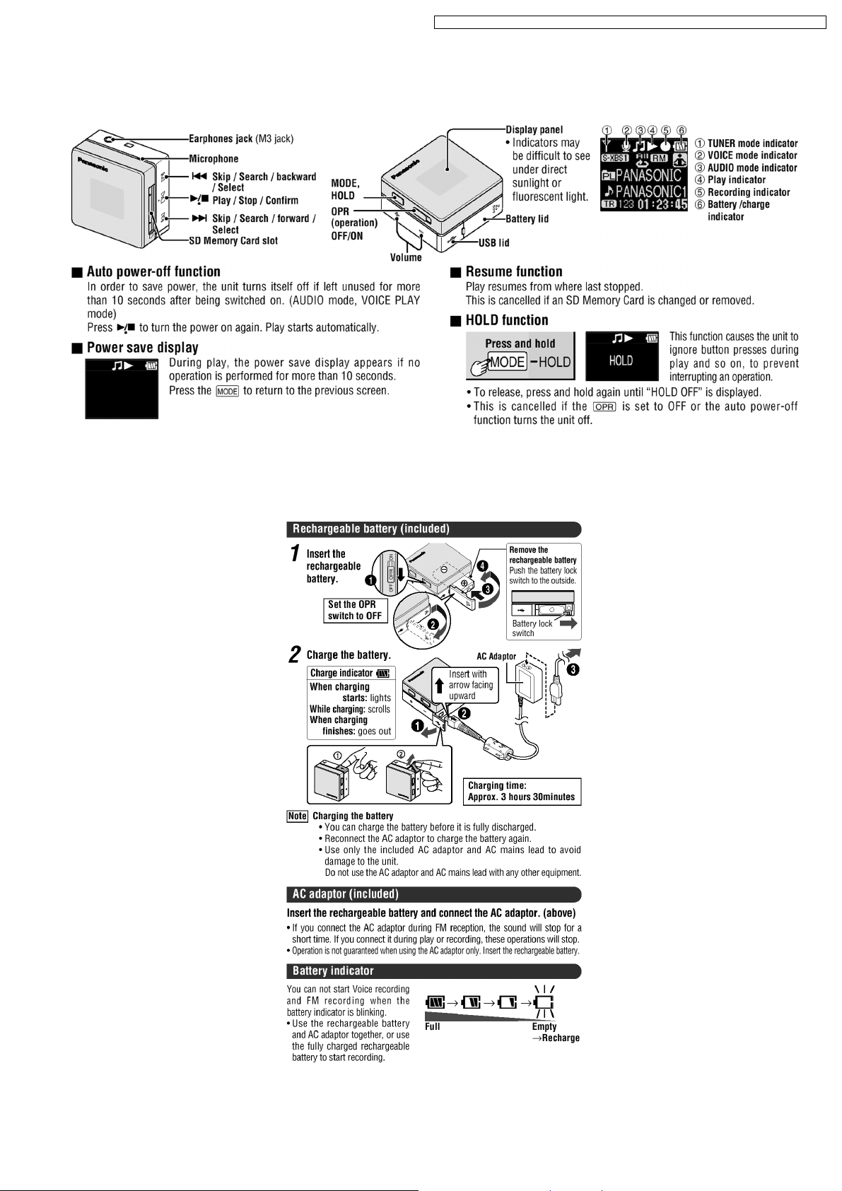
2 Location of Controls
3 Power Supply Preparations
4 Caution for AC mains lead
5 Disassembly Instructions
5.1. Removal of the rear cabinet, front cabinet and middle
cabinet
5.2. Removal of the Sub1 P.C.B., Sub2 P.C.B. and Main
P.C.B.
5.3. Removal of the EL
6 SERVICE POSITION
6.1. Extension cable and P.C.B.
6.2. Service Position
7 Precautions When Executing The Main PCB Replacement
Service
8 Service Mode
8.1. Before Entering The Service Mode
8.2. Entering The Service Mode
8.3. SERVICE 1: EL Display Mode Switching
8.4. SERVICE 2: Device Key Serial Number. Display
8.5. SERVICE 3: Control Button Operation Check & Remaining
Battery Capacity Display Check
8.6. SERVICE 4: Model & Region Display
8.7. SERVICE 5: Settings Initialization (all settings)
10
11
11
12
12
13
3
3
4
5
5
6
7
8
8
8
9
9
9
8.8. SERVICE 6: Settings Readout 13
8.9. SERVICE 7: Default Settings Writing
8.10. SERVICE 8: Card Recognition Operation Check
8.11. SERVICE 9: Audio Playback Check
8.12. SERVICE 10: Voice Playback Check
8.13. SERVICE 11: Voice Recording Check
8.14. SERVICE 12: FM Recording Check
8.15. SERVICE 13: Device Check
8.16. Error Code Table
9 Type Illustration of ICs, Transistors and Diodes
10 Schematic Diagram Notes
11 Schematic Diagram
12 Printed Circuit Board Diagram
13 Block Diagram
14 Terminal Function of ICs
14.1. IC3 (MNPH930FLDR): Microcomputer
15 Caution in use of Rechargeable Battery
16 Caution for Rechargeable Battery
17 Replacement Parts List
18 Cabinet Parts Location
19 Packaging
19.1. SV-SD100VEB/EG/GC/GK/GN
19.2. SV-SD100VPP
13
13
14
14
15
16
17
17
23
23
25
31
33
35
35
36
36
37
41
42
42
43
1 Accessories
· Stereo earphones....................................................... 1pc.
(L0BAB0000192)
· Rechargeable battery with case.......................... ..... 1pc.
(EB, EG, GC, GK, GN: RFKFHAZ10EM1)
(PP: RFKFHAZ10PM1)
· AC adaptor...................... ................. ................. ..... 1pc.
(EB, EG, GN: RFA2694)
(GC, GK: RFA2695)
(PP: RFA2693)
· AC mains lead............................................................. 1 pc.
(EB: RJA0053-3X)
(EG, GC: VJA0664)
(GK: K2CA2CA00020)
(GN: K2CJ2DA00008)
· CD-ROM (SD-Jukebox Ver.5.0LE)...........................1pc.
Supply of CD-ROM, in accordance with license protection,
is allowable as replacement parts only for customers who
accidentally damaged or lost their own.
(EB, EG, GN, PP: VFF0268-S)
(GC, GK: VFF0269-S)
· USB Cable......................................... ................. ...1pc.
(K1HA08CD0004)
· Neck lanyard...................... ................. ................. ........1pc.
(VFC4028)
2
2 Location of Controls
SV-SD100VEB / SV-SD100VEG / SV-SD100VGC / SV-SD100VGK / SV-SD100VGN / SV-SD100VPP
3 Power Supply Preparations
3
SV-SD100VEB / SV-SD100VEG / SV-SD100VGC / SV-SD100VGK / SV-SD100VGN / SV-SD100VPP
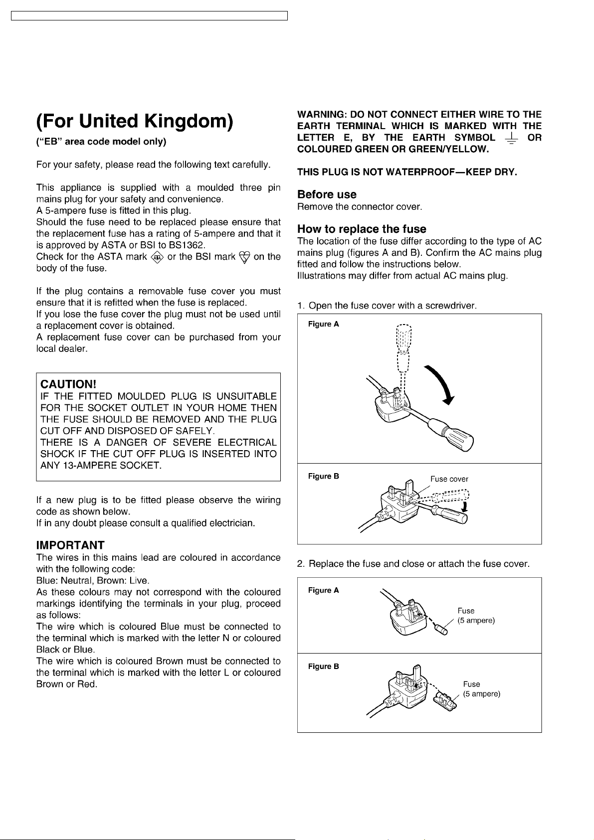
4 Caution for AC mains lead
4
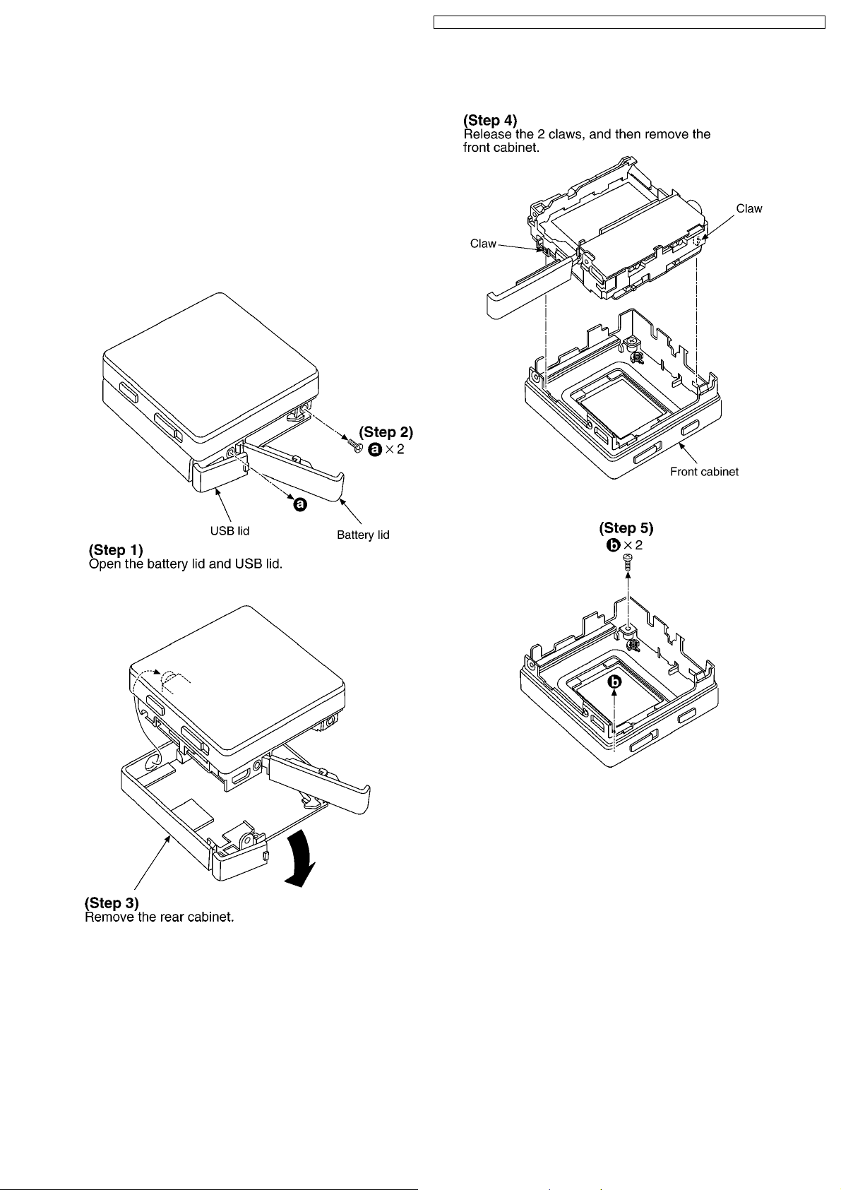
5 Disassembly Instructions
· This section describes procedures for replacing the main
components.
· For reassembly after operation checks or replacement,
reverse the respective procedures. Special reassembly
procedures are described only when required.
5.1. Removal of the rear cabinet,
front cabinet and middle
cabinet
SV-SD100VEB / SV-SD100VEG / SV-SD100VGC / SV-SD100VGK / SV-SD100VGN / SV-SD100VPP
5
SV-SD100VEB / SV-SD100VEG / SV-SD100VGC / SV-SD100VGK / SV-SD100VGN / SV-SD100VPP
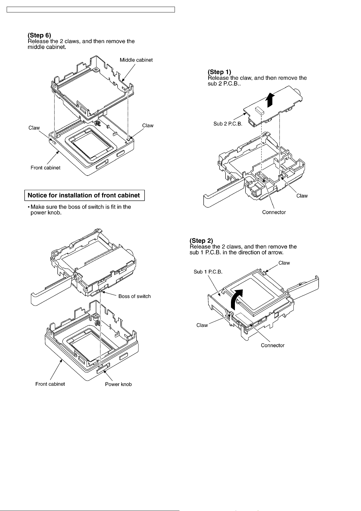
5.2. Removal of the Sub1 P.C.B.,
Sub2 P.C.B. and Main P.C.B.
· Follow the (Step 1) - (Step 4) of item 5.1.
6
SV-SD100VEB / SV-SD100VEG / SV-SD100VGC / SV-SD100VGK / SV-SD100VGN / SV-SD100VPP
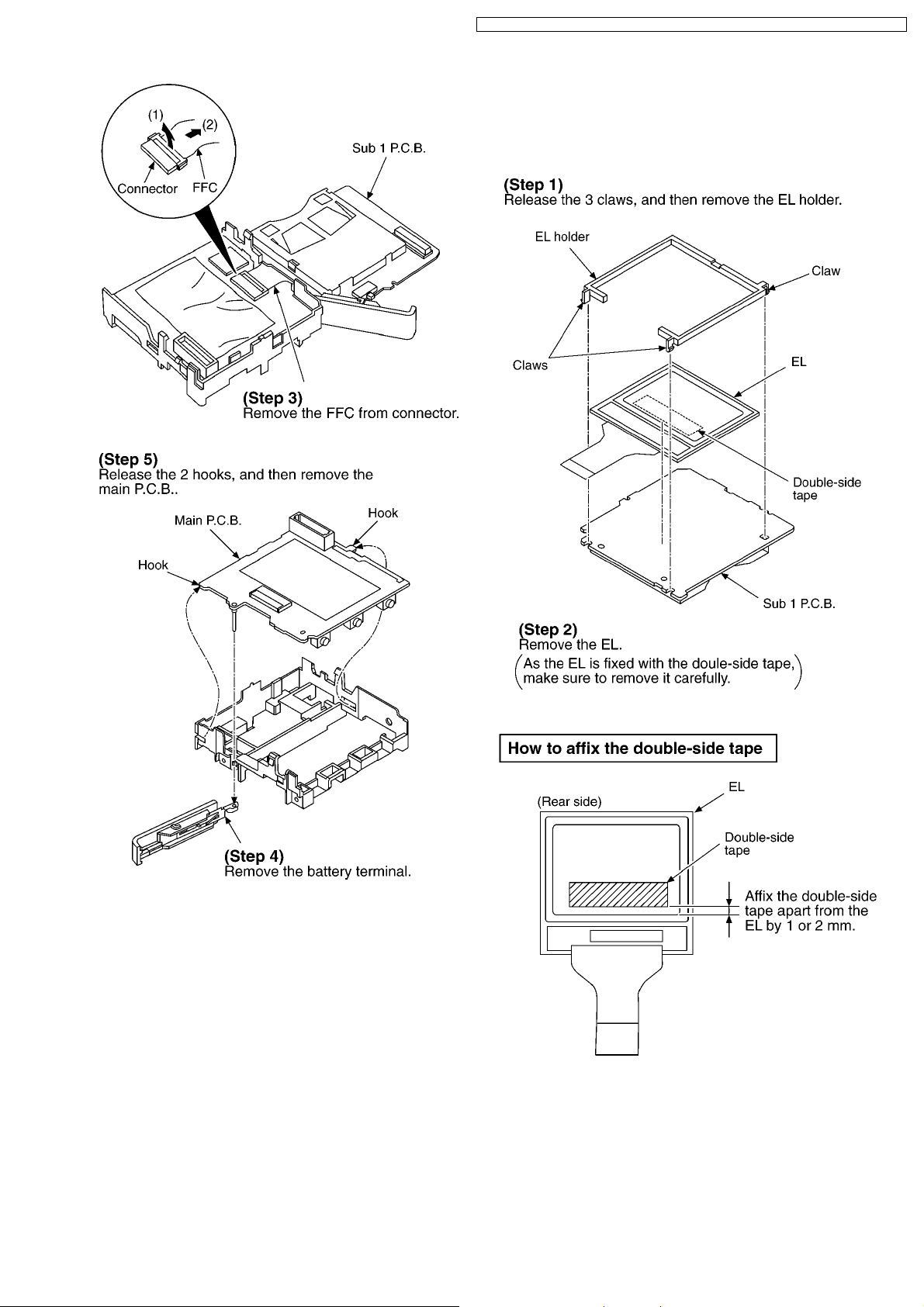
5.3. Removal of the EL
· Follow the (Step 1) - (Step 4) of item 5.1.
· Follow the (Step 2) - (Step 3) of item 5.2.
7
SV-SD100VEB / SV-SD100VEG / SV-SD100VGC / SV-SD100VGK / SV-SD100VGN / SV-SD100VPP
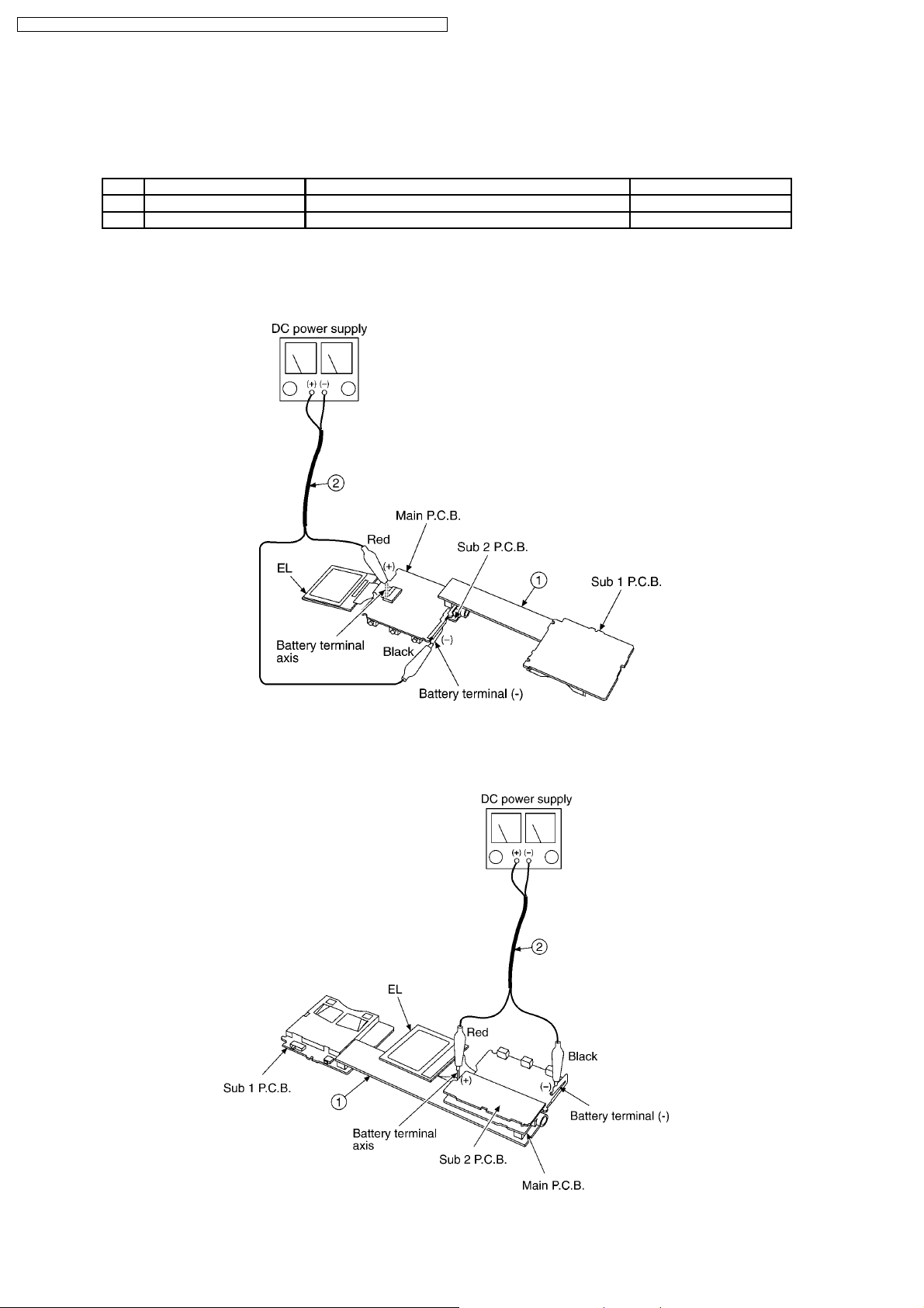
6 SERVICE POSITION
This Service Position is used for checking and replacing parts. Use the following Extension cable and P.C.B. for servicing.
6.1. Extension cable and P.C.B.
No. Parts No. Connection Form
1 RFZK0299 Main P.C.B. ~ Sub 1 P.C.B. 40 Pin Connector P.C.B.
2 VFK1576X0250 BATTERY TERMINAL (MAIN) - DC POWER SUPPLY 2PIN LEAD WITH CLIP
6.2. Service Position
Checking for the main P.C.B.(A side) and Sub 1 P.C.B.(A side).
Checking for the main P.C.B.(B side), Sub 1 P.C.B.(B side) and Sub 2 P.C.B.
Remove Sub 2 P.C.B. to check the main P.C.B.
8

SV-SD100VEB / SV-SD100VEG / SV-SD100VGC / SV-SD1 00VGK / SV-SD100VGN / SV- SD100VPP
7 Precautions When
Executing The Main PCB
Replacement Service
8 Service Mode
This mode is used to check unit operation and the condition of
the PCB, and to verify that record/playback operations are
occurring normally.
Always set the audio player to the service mode when replacing
the PCB or IC. The service mode is also used for initializing and
writing setting data.
8.1. Before Entering The Service
Mode
Preparations
The following items are required in order to perform an
operation check
· Rechargeable battery (accessory item) (must be fully
charged)
· One SD card (service mode card)
· One SD card with 8MB space available (for recording
check)
· Accessory USB cable
· Personal computer with accessory SD-Jukebox Ver.5.0
installed
8.1.1. Preparing The Service Mode SDCard
Preparation procedure for SD card
1. Connect the audio player to the personal computer
where the accessory SD-Jukebox Ver.5.0 software is
installed.
2. Insert the SD-card.
3. Use SD-Jukebox Ver.5.0 to write a music file to the SDcard.
4. End SD-Jukebox Ver.5.0 operation.
5. Download the necessary files (SD100TST.SDA and
FLASH_WR.BIN) from TSN-WEB (Support Information
From NWBG- PAVC).
6. Copy the files (SD100TST.SDA and FLASH_W R.BIN)
into the SD-card´s root directory.(The personal
computer recognizes the audio player as a removable
disk.)
7. Disconnect the audio player from the personal
computer.
8. Perform a voice recording to the SD-card at the audio
player.
Note:
If you may not be able to complete a downloding from
the TSN-WEB page, Please order a jig SD card
(RFKZ0294) or obtain the files (SD100TST.SDA and
FLASH_WR.BIN) through your local Panasonic Service
Organization.
The supplied device key loaded PCB (REP3902A-M) does not
contain the regional default settings file.
That file must be written to the audio player by the procedure
shown below.
1. Execute the "8.9. SERVICE 7: Default Settings Writing"
procedure".
Preparation procedure for jig SD card
1. Connect the audio player to the personal computer
where the accessory SD-Jukebox Ver.5.0 software is
installed.
2. Insert the jig SD-card (RFKZ0294).
3. Open the jig SD-card from the personal computer. (The
personal computer recognizes the audio player as a
removable disk.)
· The SD-card´s root directory contains the
SD100TST.SDA service mode file, and
FLASH_WR_XXXXXXXX.BIN
settings file.
* "XXXXXXXX" denotes the region and model
names.
4. Change the file name of the desired region´s
FLASH_WR_XXXXXXXX.BIN to "FLASH_WR.BIN".
5. Use SD-Jukebox Ver.5.0 to write a music file to the SDcard.
6. End SD-Jukebox Ver.5.0 operation.
7. Disconnect the audio player from the personal
computer.
8. Perform a voice recording to the SD-card at the audio
player.
* Use the service mode´s "audio playback check" and
"voice playback check" functions for audio files and voice
files.
Because the time required for this operation is determined
by the length of the file, the file should be as short as
possible.
*
regional default
8.1.2. Preparing The Recording Check
SD-Card
1. Connect the audio player to the personal computer where
the accessory SD-Jukebox Ver.5.0 software is installed.
2. Format an 8MB SD-card at SD-Jukebox Ver.5.0.
3. Disconnect the audio player from the personal computer.
* This card will be used for the "voice recording check"
and "FM recording check" functions. The time required for
this operation depends on the SD-card capacity.
When using an 8MB SD-card, one "SD-card formatting, full
recording and playback" cycle takes approximately 1 hour.
9
SV-SD100VEB / SV-SD100VEG / SV-SD100VGC / SV-SD1 00VGK / SV-SD100VGN / SV- SD100VPP
8.2. Entering The Service Mode
1. Place a fully charged battery in the audio player and turn
the power ON.
2. Select the audio mode.
3. Insert the service mode SD-card in the audio player.
· A playback operation begins.
4. Press the [STOP] button to stop the playback.
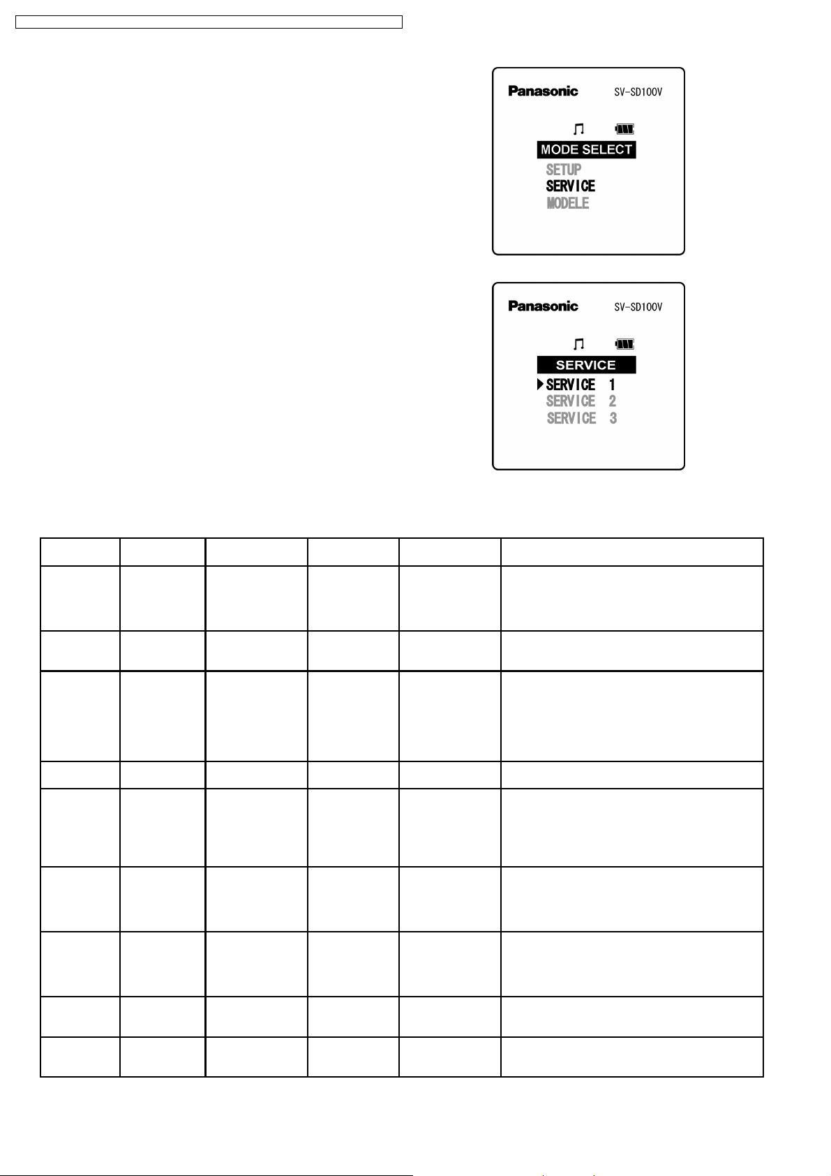
5. Press the [MODE] button one time to display the mode
selection screen (Fig.S1).
6. Use the [FWD-Skip] and [REW-Skip ] buttons to select the
desired SERVICE item, then press the [PLAY/STOP] button
to display the service mode menu (Fig.S2).
7. At the service mode menu, use the [FWD-Skip] and [REWSkip] buttons to select the desired menu item, then press
the [PLAY/STOP] button to execute that menu.
Note:
Menus other than SERVICE 1 cannot be executed in a
continuous manner.
Fig.S1
8.2.1. Service Mode Function & Canceling The Service Mode
Menu Item Service Mode
Description
SERVICE 1 Switches the EL
display mode.
SERVICE 2 Device key
serial number
display.
SERVICE 3 Control button
operation
checks and
remaining
battery capacity
display check
SERVICE 4 Model & region
display
SERVICE 5 Initializes
settings (all
settings)
SERVICE 6 Reads out the
settings
information.
SERVICE 7 Writes the
default settings.
SERVICE 8 Card
recognition
check
SERVICE 9 Checks the
audio playback
operation.
Operation After
Menu Selection
Returns to standard
screen
Service mode is
executed.
Service mode is
executed.
Service mode is
executed.
Service mode is
executed.
Service mode is
executed.
Service mode is
executed.
Service mode is
executed.
Service mode is
executed.
Buttons Used Canceling The
[FWD-Skip],
[REW-Skip],
[PLAY/STOP]
(menu operation
only)
None Turn power OFF. Verifies that the device key is written without error to
[FWD-Skip],
[REW-Skip],
[MODE], [VOL+],
[VOL-] (AD value
measurement)
None Turn power OFF. Displays the model and region information. This
[FWD-Skip],
[REW-Skip],
[PLAY/STOP]
(menu operation
only)
None Turn power OFF
None Turn power OFF
None Open the battery
None Open the battery
Service Mode
Turn power OFF, or
switch back to EL
display mode.
Turn power OFF. Displays the rechargeable battery voltage, and the
Turn power OFF
(power is
automatically
turned OFF when
processing ends).
(power is
automatically
turned OFF when
processing ends).
(power is
automatically
turned OFF when
processing ends).
cover.
cover.
Because the display content must be checked
during service mode execution, the EL display is
always ON at this menu .
the main PCB´s IC4 (Flash ROM).
KEY IN voltage´s AD conversion values
(hexadecimal) at the [FWD-Skip], [REW-Skip],
[MODE], [VOL+], [VOL-] key operations.
The AD conversion value is used for button
operation checks and for the remaining battery
capacity display.
content cannot be changed.
Initializes model & region settings, and initializes
resume information and the tuner´s preset
frequency.
* This differs from the standard mode´s setting menu
initialization in that the tuner´s preset is also
initialized.
Verifies that the settings information is written to IC4
(Flash ROM) without error.
Writes the service mode SD-card´s default setting
file (FLASH_WR.BIN) content to IC4 (Flash
ROM).The model & region settings are written as a
set.
Verifies that the SD-card (where audio file is saved)
can be recognized.
Performs repeat playba ck and checks for audio
playback errors.
Fig.S2
Service Mode Function
10
SV-SD100VEB / SV-SD100VEG / SV-SD100VGC / SV-SD1 00VGK / SV-SD100VGN / SV- SD100VPP
Menu Item Service Mode
Description
SERVICE 10 Checks the
voice playback
operation.
SERVICE 11 Checks the
voice recording
operation.
SERVICE 12 Checks the FM
recording
operation.
SERVICE 13 Performs a
device check.
Operation After
Menu Selection
Service mode is
executed.
Service mode is
executed.
After tuner tuning,
Service mode is
executed.
Service mode is
executed.
Buttons Used Canceling The
None Open the battery
None Open the battery
[FWD-Skip],
[REW-Skip],
[PLAY/STOP]
(during tuner
tuning only)
None Open the battery
Service Mode
cover.
cover.
Open the battery
cover.
cover.
Service Mode Function
Performs repeat playback and checks for voice
playback errors.
Repeats the "SD-card formatting, full recording
(recording until card´s capacity is completely used),
and playback" procedure, and checks for voice
recording errors.
Performs "FM radio reception, repeats the "SD-card
formatting, full recording (recording until card´s
capacity is completely used), recording, and
playback" procedure, and checks for FM recording
errors.
Checks for malfunctions at the main PCB´s IC8 and
IC4, and peripheral circuitry.
* Auto power OFF in operation check modes
Although the audio player is equipped with an auto power OFF function, this function is disabled when executing all operation
check mode menu functions except SERVICE 1.
An automatic power OFF which is unrelated to the auto power OFF function occurs at the completion of SERVICE 5, 6, 7.
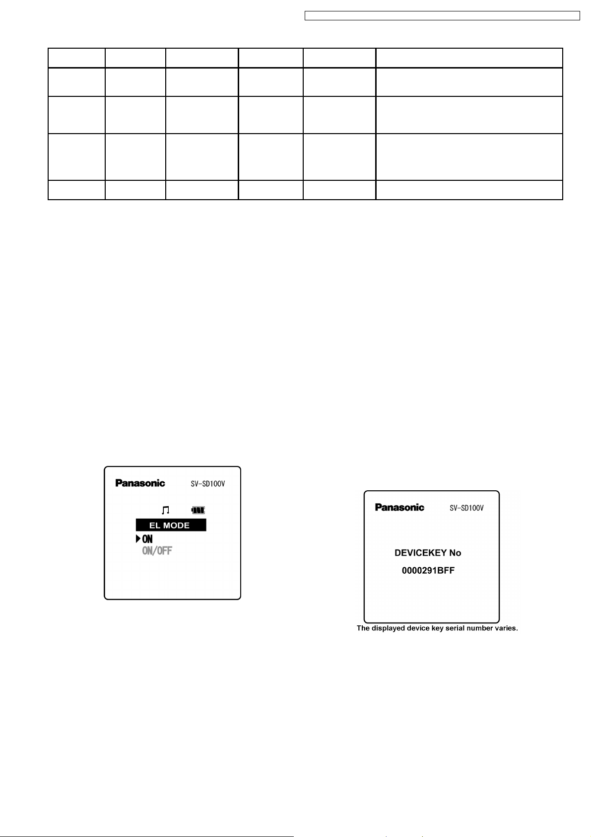
8.3. SERVICE 1: EL Display Mode
Switching
Because the display content must be checked during service
mode execution, the EL display is always ON at this menu.
1. Execute the SERVICE 1 menu as described in section 8.2
(Entering The Service Mode), and display the EL display
mode switching screen (Fig.S3).
2. Use the [FWD-Skip] and [REW-Skip] buttons to select
"ON", and then press the [PLAY/STO P] button to execute
display mode switching.
Note:
Another SERVICE mode should be executed within 15
seconds after switching is performed. If the auto power OFF
function is activated, the system returns to the "display
ON/OFF control enabled" mode.
8.4. SERVICE 2: Device Key Serial
Number. Display
This display is used to verify that the device key is written to the
main PCB´s IC4 (Flash ROM) without error.
If the device key serial number fails to display, there is a
problem with the IC4 (Flash ROM). As the IC4 (Flash ROM)
cannot be replaced independently, replace the main PCB with
a device key loaded PCB (REP3902A-M).
Note: Main PCB replacement should be performed with
reference to section 7 (Precautions When Executing The
Main PCB Replacement Service).
1. Execute the "8.3 SERVICE 1: EL Display Mode Switching"
procedure so that EL is always ON.
2. Execute the SERVICE 2 menu as described in section 8.2
(Entering The Service Mode), in order to display 5 bytes of
the device key serial number. (Fig.S4).
3. Turn the power OFF to complete the procedure.
Fig.S3
Fig.S4
11
SV-SD100VEB / SV-SD100VEG / SV-SD100VGC / SV-SD1 00VGK / SV-SD100VGN / SV- SD100VPP
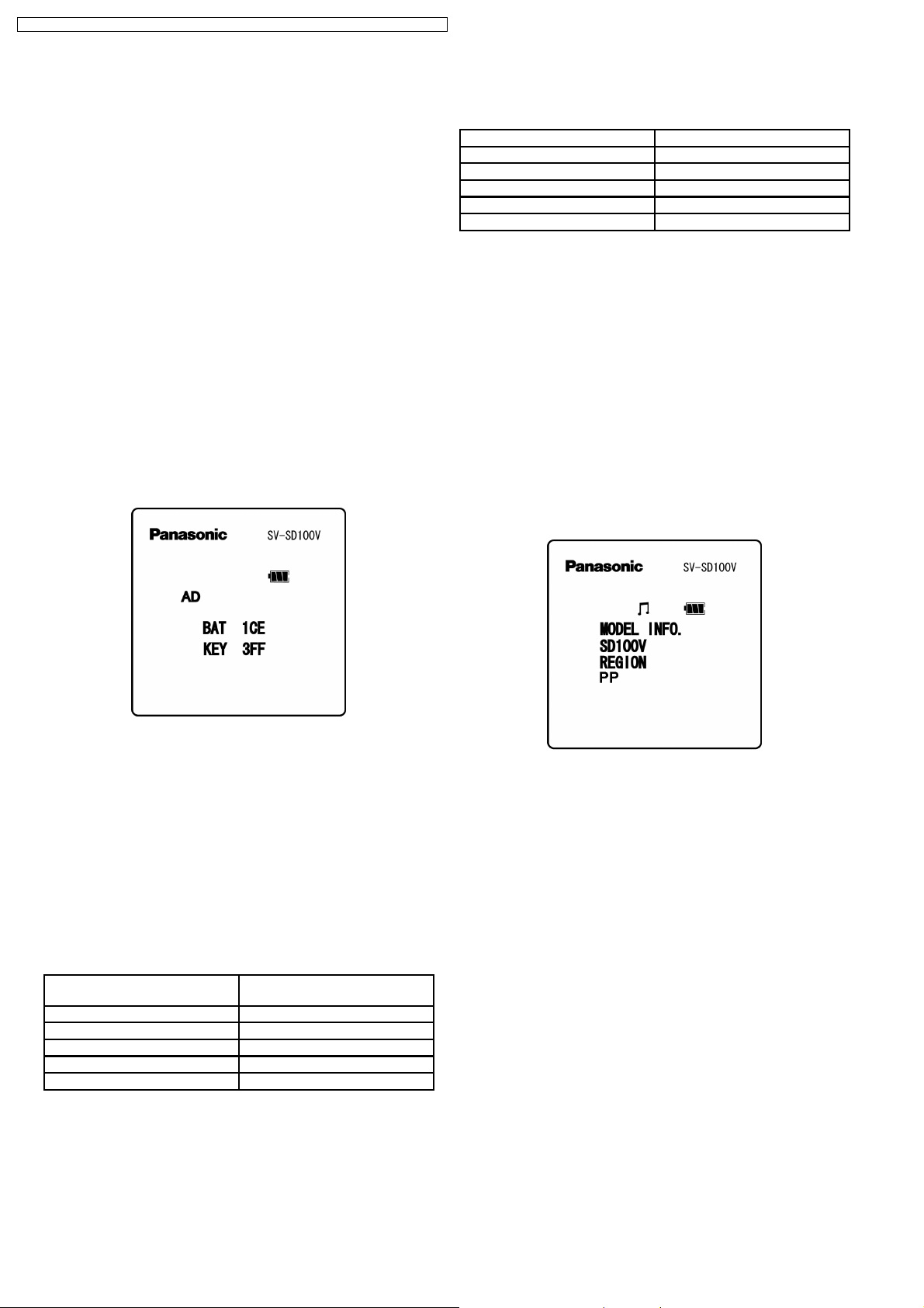
8.5. SERVICE 3: Control Button
Operation Check & Remaining
Battery Capacity Display
Check
Displays the rechargeable battery voltage, and the KEY IN
voltage AD conversion values (hexadecimal) at the [FWDSkip], [REW-Skip ], [MODE], [VOL+], [VOL-] key operations.
The AD conversion value is used for button operation checks
and for the remaining battery capacity display.
1. Execute the "8.3 SERVICE 1: EL Display Mode Switching"
procedure so that EL is always ON.
2. Execute the SERVICE 3 menu as described in section 8.2
(Entering The Service Mode), in order to display the AD
conversion values (hexadecimal) (Fig.S5).
3. Check the BAT´s AD conversion value and the remaining
battery capacity display.
4. Press each of the [FWD-Skip], [REW-Skip], [MODE],
[VOL+], [VOL-] buttons and verify the changes in the KEY´s
AD conversion value.
5. Turn the power OFF to complete the procedure.
8.5.1.2. KEY (Control Button´s AD Value)
Displays the AD value judgment for the button operation.
Button Operation AD Conversion Value
MODE 000 ~ 0CA
F-SKIP 151 ~ 1CE
R-SKIP 1CF ~ 259
Vol+ 25A ~ 2CB
Vol- 2CC ~ 34E
If the AD conversion value displayed at the button operation is
outside the range shown in the table, this may indicate a
hardware malfunction.
8.6. SERVICE 4: Model & Region
Display
Displays the model and region information. This content cannot
be changed.
1. Execute the "8.3 SERVICE 1: EL Display Mode Switching"
procedure so that EL is always ON.
2. Execute the SERVICE 4 menu as described in section 8.2
(Entering The Service Mode), in order to display the model
and region information (Fig.S6).
3. Turn the power OFF to complete the procedure.
Fig.S5
8.5.1. AD Conversion Values
8.5.1.1. BAT (Remaining Battery Capacity
AD Value)
The BAT display (hexadecimal) indicates the voltage of the
internal rechargeable battery.
The internal rechargeable battery voltage = 2.9 (V) x [BAT
display content] / 1024.
[Ex] When the BAT value is "1CC" ("460" as decimal value):
Internal rechargeable battery voltage = 2.9 x 460 / 1024 =
1.3027....= 1.303 (V)
Remaining Battery Voltage
Display
3 battery marks 1C3 < Batt
2 battery marks 1B3 < Batt < or = 1C3
1 battery mark 19B < Batt < or = 1B3
Blinking battery mark 161 < Batt < or = 19B
Low battery voltage Batt < or = 161
AD Conversion Value
Fig.S6
12
SV-SD100VEB / SV-SD100VEG / SV-SD100VGC / SV-SD1 00VGK / SV-SD100VGN / SV- SD100VPP
8.7. SERVICE 5: Settings
Initialization (all settings)
Initializes the model & region settings, as well as resume
information, and the tuner´s preset frequency.
* Unlike the initialization item at the standard mode´s setting
menu, the tuner preset information is also initialized to the
factory settings.
1. Execute the SERVICE 5 menu as described in section 8.2
(Entering The Service Mode).
· After settings are initialized, the power is automatically
turned OFF.
8.8. SERVICE 6: Settings Readout
Verifies that settings information has been written to the IC4
(Flash ROM) without error.
1. Execute the SERVICE 6 menu as described in section 8.2
(Entering The Service Mode).
· Reads out the IC4 (Flash ROM) settings information,
and writes it to the SD-card.
· The power is then automatically turned OFF.
2. Use the accessory USB cable to connect the audio player
to the personal computer.
3. From the personal computer, verify that the default settings
file (FLASH_RD.BIN) has been written to the SD-card.
* The presence of the FLASH_RD.BIN file on the SD-card
indicates that the settings information has been written to the
IC4 (Flash ROM) without error.
If the FLASH_RD.BIN file is not present on the SD-card,
execute the "8.9. SERVICE 7: Default Settings Writing"
procedure.
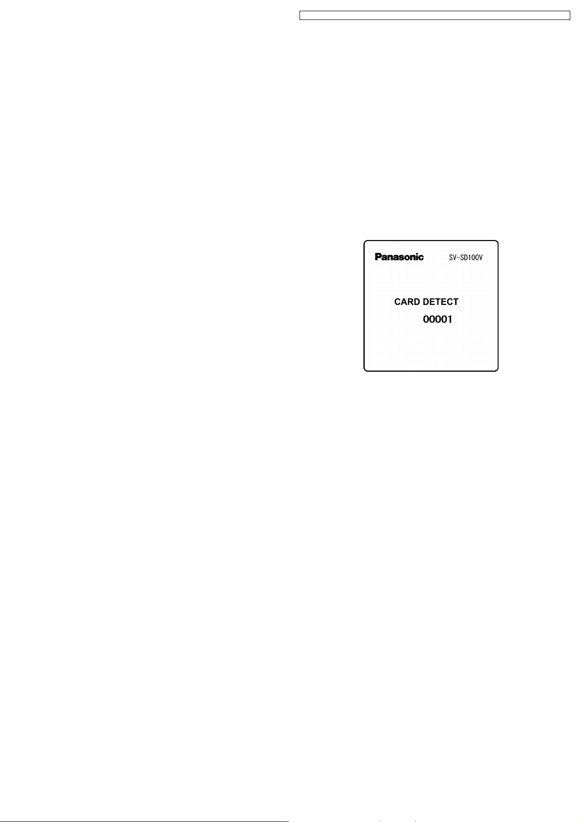
8.10. SERVICE 8: Card Recognition
Operation Check
Verifies that the SD-card (where audio file is saved) can be
recognized.
1. Execute the "8.3 SERVICE 1: EL Display Mode Switching"
procedure so that EL is always ON.
2. Execute the SERVICE 8 menu as described in section 8.2
(Entering The Service Mode), in order to display the card´s
detection count screen (Fig.S7).
3. Remove the service mode SD-card, then insert it again.
· The count value increases by 1 (1 card insertion) after
the microcomputer reads the default data from the SDcard.
4. Open the battery cover to complete the procedure.
Fig.S7
8.9. SERVICE 7: Default Settings
Writing
Writes the service mode SD-card´s default settings file
(FLASH_RD.BIN) to the IC4 (Flash ROM).
The model & region settings are written to the audio player by
this procedure.
1. Execute the SERVICE 7 menu as described in section 8.2
(Entering The Service Mode).
· Writes the default settings to the IC4 (Flash ROM), and
the power is then automatically turned OFF.
2. Execute the "SERVICE 6: Settings Readout" procedure to
verify that the default settings have been written to the IC4
(Flash ROM).
* If the "SERVICE 6: Settings Readout" procedure reveals that
the FLASH_RD.BIN file has not been written to the SD-card,
this indicates a problem with the IC4 (Flash ROM). As the IC4
(Flash ROM) cannot be replaced independently, replace the
main PCB with a device key loaded PCB (REP3902A-M).
Note: Main PCB replacement should be performed with
reference to section 7 (Precautions When Executing The
Main PCB Replacement Service).
13
 Loading...