

Panasonic SCZT2 Operating Instructions
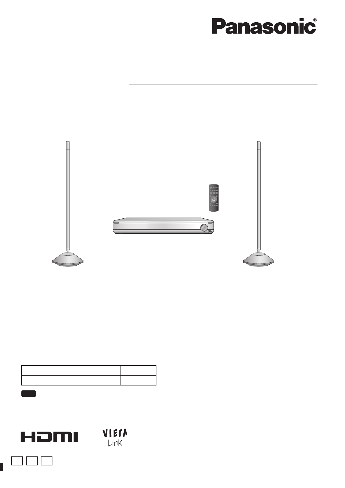
Operating Instructions
Home Theater Audio System
Model No. SC-ZT2
Dear customer
Thank you for purchasing this product.
For optimum performance and safety, please read these instructions carefully.
Before connecting, operating or adjusting this product, please read the instructions completely.
Please keep this manual for future reference.
SC-ZT2 Components
Main unit (Control box) SU-ZT2
Speakers SB-ZT2
Note
“E”, “GN” and “GS” are indicated on the packaging box.
E GN GS
VQT2R71
Caution for AC Mains Lead
Safety precautions
(For the United Kingdom, Republic of Ireland, Saudi Arabia, Kuwait,
Malaysia and Hong Kong)
For your safety, please read the following text carefully.
This appliance is supplied with a moulded three pin mains plug for
your safety and convenience.
A 5-ampere fuse is fi tted in this plug.
Before use
Should the fuse need to be replaced please ensure that the
replacement fuse has a rating of 5-ampere and that it is approved by
ASTA or BSI to BS1362.
Check for the ASTA mark
fuse.
If the plug contains a removable fuse cover you must ensure that it is
refi tted when the fuse is replaced.
If you lose the fuse cover the plug must not be used until a
replacement cover is obtained.
A replacement fuse cover can be purchased from your local dealer.
CAUTION!
IF THE FITTED MOULDED PLUG IS UNSUITABLE FOR THE
SOCKET OUTLET IN YOUR HOME THEN THE FUSE SHOULD
BE REMOVED AND THE PLUG CUT OFF AND DISPOSED OF
SAFELY.
THERE IS A DANGER OF SEVERE ELECTRICAL SHOCK IF THE
CUT OFF PLUG IS INSERTED INTO ANY 13-AMPERE SOCKET.
If a new plug is to be fi tted please observe the wiring code as stated
below.
If in any doubt please consult a qualifi ed electrician.
IMPORTANT
The wires in this mains lead are coloured in accordance with the
following code:
Caution for AC Mains Lead/Safety precautions
Blue: Neutral, Brown: Live.
As these colours may not correspond with the coloured markings
identifying the terminals in your plug, proceed as follows:
The wire which is coloured Blue must be connected to the terminal
which is marked with the letter N or coloured Black or Blue.
The wire which is coloured Brown must be connected to the terminal
which is marked with the letter L or coloured Brown or Red.
WARNING: DO NOT CONNECT EITHER WIRE TO THE EARTH
TERMINAL WHICH IS MARKED WITH THE LETTER E, BY THE
EARTH SYMBOL
THIS PLUG IS NOT WATERPROOF–KEEP DRY.
Before use
Remove the connector cover.
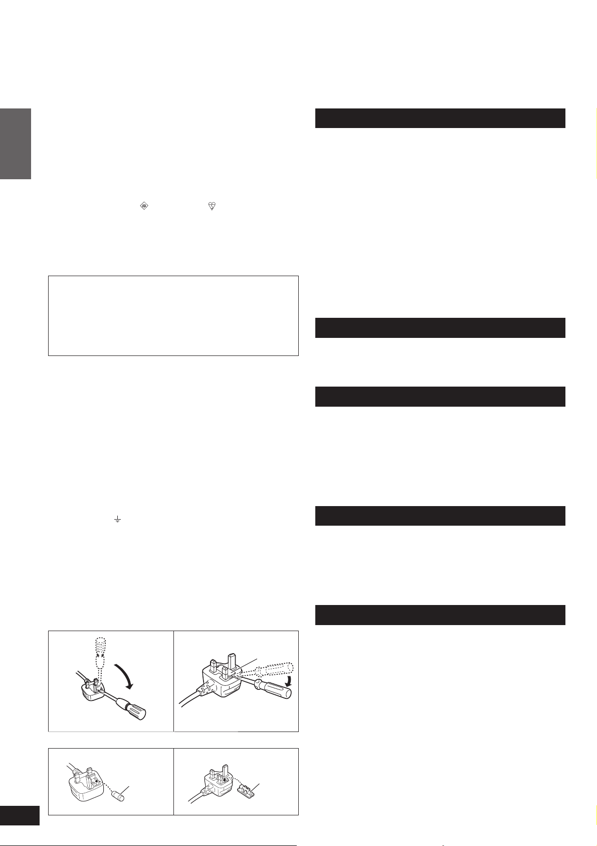
How to replace the fuse
The location of the fuse differ according to the type of AC mains plug
(fi gures A and B). Confi rm the AC mains plug fi tted and follow the
instructions below.
Illustrations may differ from actual AC mains plug.
1. Open the fuse cover with a screwdriver.
Figure A Figure B
or the BSI mark on the body of the
OR COLOURED GREEN OR GREEN/YELLOW.
Fuse cover
Placement
Set the system up on an even surface away from direct sunlight, high
temperatures, high humidity, and excessive vibration. These conditions
can damage the system and other components, thereby shortening
the system’s service life.
Do not hang from or climb on the system. This may result in serious
injury.
Do not use this device in hospitals and other places where electric
medical devices are installed.
Do not use this device near automatic doors, fi re alarms and other
automatically controlled apparatuses.
Do not hold the speaker with one hand.
Before attaching the leg cushion on the base parts to prevent tilt or
rattle on the fl oor, make sure there are no people in the surrounding
area.
Do not insert your hand or foot into the opening of side surface of base
part.
Do not turn on the speakers with foot or vacuum cleaner carelessly.
Do not use this device as a plaything.
Voltage
Do not use high voltage power sources. This can overload the system
and cause a fi re.
Do not use a DC power source. Check the source carefully when
setting the system up on a ship or other place where DC is used.
AC mains lead protection
Ensure the AC mains lead is connected correctly and not damaged.
Poor connection and lead damage can cause fi re or electric shock. Do
not pull, bend, or place the system on the lead.
Grasp the plug fi rmly when unplugging the lead. Do not move the
system if AC mains lead is still connected to socket outlet. Pulling the
AC mains lead can cause electric shock.
Do not handle the plug with wet hands. This can cause electric shock.
Remove AC mains plug from socket outlet when not using for a long
period.
Foreign matter
Do not let metal objects fall inside the system. This can cause electric
shock or malfunction.
Do not let liquids get into the system. This can cause electric shock or
malfunction. If this occurs, immediately disconnect the system from the
AC mains lead and contact your dealer.
Do not spray insecticides onto or into the system. They contain
fl ammable gases which can ignite if sprayed into the system.
Service
Do not attempt to repair this unit by yourself. If sound is interrupted,
indicators fail to light, smoke appears, or any other problem that is
not covered in these instructions occurs, disconnect the AC mains
lead and contact your dealer or an authorized service centre. Electric
shock or damage to the system can occur if the system is repaired,
disassembled or reconstructed by unqualifi ed persons.
Extend operating life by disconnecting the system from the AC mains if
it is not to be used for a long time.
2
VQT2R71
2. Replace the fuse and close or attach the fuse cover.
Figure A Figure B
Fuse
(5 ampere)
Fuse
(5 ampere)
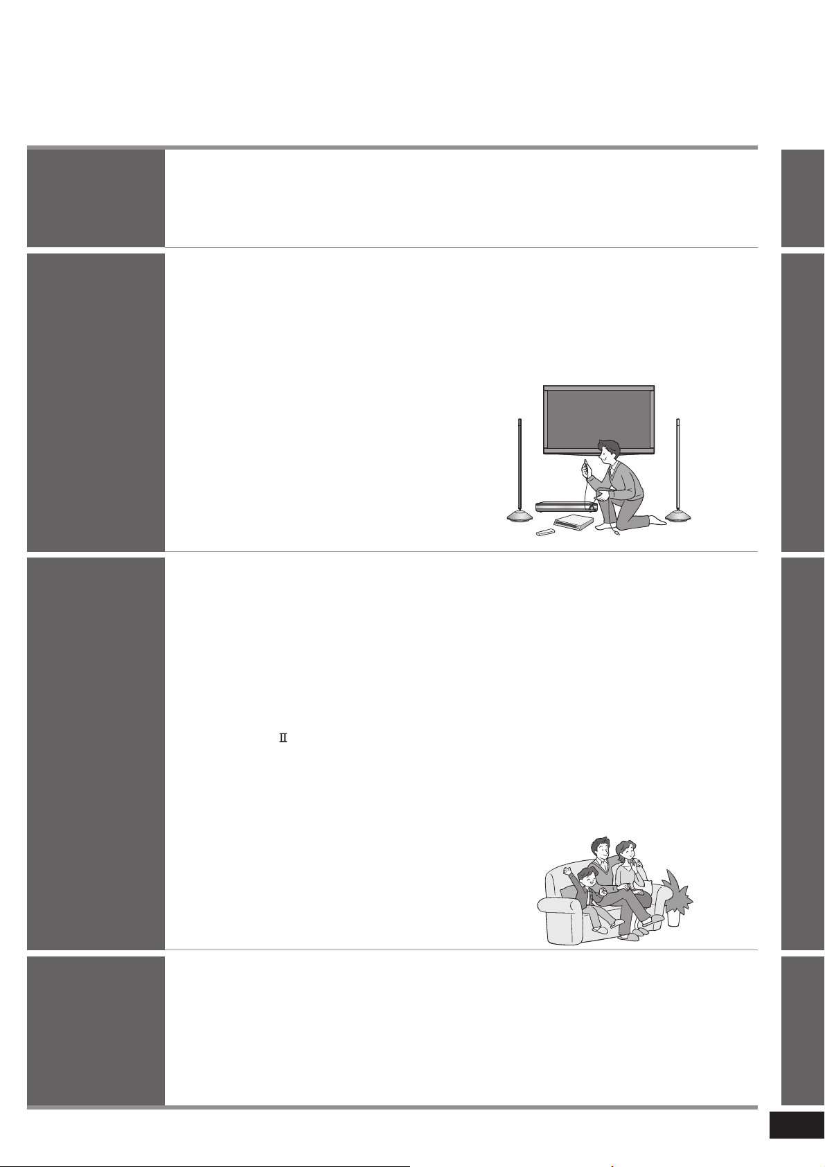
Table of contents
Before use
Connection
Play
Caution for AC Mains Lead ...........2
Safety precautions ........................2
Setting up your Home
Theater system ..............................4
Installation ....................... 9
Wireless functions ...........................................9
Home Theater connections
... 10
Basic connections ........................ 10
Connecting equipment with HDMI terminal
(TV, DVD recorder, etc.)
Connecting STB etc. .....................................11
Setting for automatically switching the input source to STB
Connecting cables to audio terminals (DVD player, etc.)
.................................... 10
.....11
.... 11
Connecting equipment without HDMI
terminal (DVD player, VCR, etc.)
........ 12
Other connections ........................ 13
To connect a second set of equipment that supports HDMI
To connect audio equipment (CD player, etc.)
To connect a subwoofer (not supplied) .........13
.....13
.....13
AC mains lead connection ............... 14
Enjoying movies and
music ............................. 18
Enjoying sound fi eld effects ............ 19
Dolby Virtual Speaker ................................... 19
SFC (Sound Field Control) ............................19
Cancelling sound fi eld effects .......................19
When connecting the surround speakers .....19
Surround playback ........................................19
SFC (Sound Field Control) ............................19
Dolby Pro Logic .......................................... 19
Using the VIERA Link
“HDAVI Control™” ....................... 20
What you can do with VIERA Link
“HDAVI Control” ............................................. 20
Functions and settings ............... 22
Using “WHISPER-MODE SURROUND” ....... 22
Using “GAME” ...............................................22
Muting ...........................................................22
Adjusting the bass (woofer part) output ........ 22
Adjusting the surround speaker output ......... 22
Adjusting the surround speaker output
using the test signal ...................................... 23
Supplied accessories ....................5
Control guide ................................. 6
Remote control preparation .........8
Speaker setting .............15
Setting the speakers ..................... 15
Checking the speaker setting ...... 16
Installing surround speakers ....... 16
Setting surround speakers .......... 17
Changing the number of speakers to 4 .........17
Setup menu items .........................................23
Adjusting sound quality .................................23
Adjusting the volume balance of front speakers ...
Setting distances ...........................................24
Setting 7.1-channel virtual surround ............. 24
Reducing standby power consumption
(In standby condition (HDMI off mode)) ........24
VIERA Link “HDAVI Control” setting .............. 25
Adjusting the time lag between audio and
video by delaying audio output ......................25
Switching between dual sounds ....................25
Clear audio at low volume .............................25
Switching the attenuator ...............................25
Switching the input signal detection setting
Reset (factory settings) .................................26
When other equipment (mini component system,
AV amp, etc.) manufactured by Panasonic operates
with the remote control operations of this system
23
......26
. ....26
Before use
ConnectionPlay
Error messages ...........................27
Using with headphones .............. 27
Troubleshooting
and other
information
Specifi cations .............................. 27
Troubleshooting guide ................ 28
Digital audio signals supported
by this system .............................. 29
Maintenance .................................29
Glossary ....................................... 30
other information
Troubleshooting and
3
VQT2R71
Setting up your Home Theater system
Step
1
Installing the speakers
You can make your preferred setting because speaker
cords are not required.
• Make sure to place the speakers on a flat, stable surface so there is no
Before use
Step
danger of them falling over.
• AC mains lead (supplied) is necessary for each speaker.
Connecting the television and DVD recorder
2
Setting up your Home Theater system
(Peripheral equipment and cables are not supplied unless otherwise mentioned.)
Install and connect the main unit and other equipment.
Connecting TV
Necessary cable:
(For images and audio)
Connecting recorder
Necessary cable:
(For images and audio)
HDMI cable: 1 (not supplied)
HDMI cable: 1 (not supplied)
(➜ page 9)
(➜ page 10)
I need 2 HDMI
cables for
connections.
4
VQT2R71
Step
3
Step
4
• Connect with an HDMI cable for high-quality audio and video.
• This connection requires HDMI terminals on both the television and the DVD recorder.
Setting the speakers
(➜ page 15)
Use the remote control for speaker setting.
• Make sure to set the speakers when using for the first time after purchase.
Enjoying movies and music
(➜ page 18)
Enjoy surround sound with DVDs, TV, and other
sources.
• Audio is transmitted wirelessly.
You can enjoy more dynamic surround playback with this
system by installing Panasonic surround speakers
SB-ZT2. (➜ page 16)
This system supports 3D images.
By connecting with 3D compatible television or recorder etc., you can
enjoy dynamic visions of commercially available 3D image software or
3D broadcasting programs with the effect of sense of being in the actual
scene.
㨪ۭ
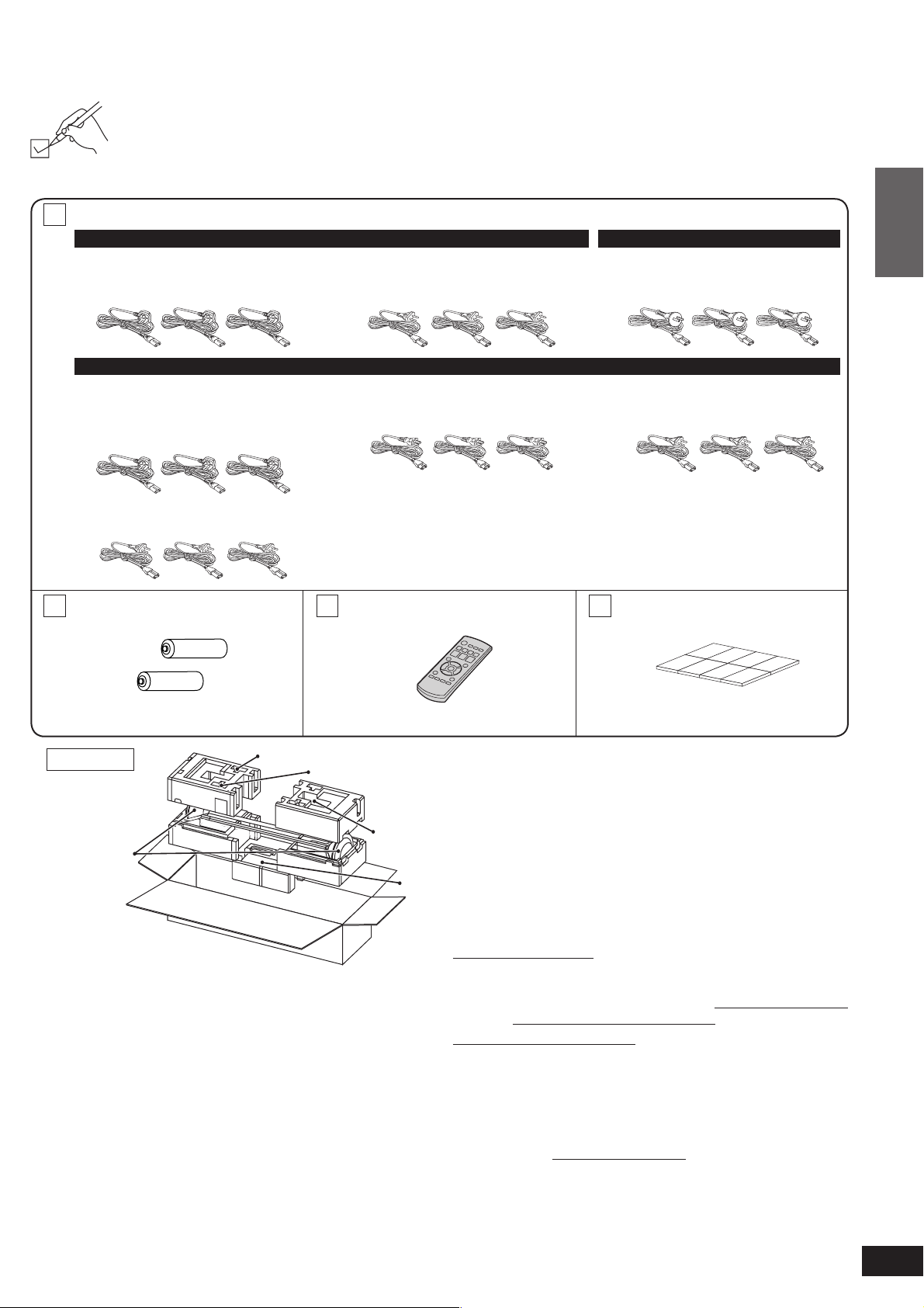
Supplied accessories
Please check and identify the supplied accessories.
Use numbers indicated in parentheses when asking for replacement parts.
(Product numbers correct as of February 2010. These may be subject to change.)
Supplied accessories differ depending on the symbols (E, GN, GS) indicated on the packaging box.
Use correct accessories according to the region for use.
3 AC mains leads
For E
(For the United Kingdom and
Republic of Ireland)
(K2CZ3YY00005)
For GS
(For Saudi Arabia, Kuwait,
Malaysia and Hong Kong)
(K2CZ3YY00005)
(220 to 240 V)
(For continental Europe)
(K2CQ2CA00007)
(For Saudi Arabia)
(K2CA2CA00031)
(110 to 127 V)
For GN
(For Australia and New Zealand)
(K2CJ2DA00010)
(For Thailand)
(K2CP2CA00001)
Before use
Supplied accessories
(For others)
(K2CQ2CA00007)
2 Batteries
(R6, AA)
Packing plan
Speakers
Remote control
Batteries
1 Remote control
(N2QAYB000417)
AC mains
leads
Main unit
Sales and Support Information
(For the United Kingdom and Republic of Ireland customers)
Customer Care Centre
• For customers within the UK: 0844 844 3852
• For customers within the Republic of Ireland: 01 289 8333
• Visit our website for product information www.panasonic.co.uk
• E-mail: customer.care@panasonic.co.uk
Direct Sales at Panasonic UK
• For customers: 0844 844 3856
•
• Or go on line through our Internet Accessory ordering
• Most major credit and debit cards accepted.
• All enquiries transactions and distribution facilities are
• It couldn’t be simpler!
• Also available through our Internet is direct shopping for a
Leg cushion (1 sheet: 8 pieces)
(RFA3045-2)
Keep the leg cushion out of reach
of children to prevent swallowing.
• When taking out speakers, hold the pole and base parts
(➜ page 7).
Order accessory and consumable items for your product with ease
and confidence by phoning our Customer Care Centre
Monday-Thursday 9:00am-5:30pm,
Friday 9:30am-5:30pm (Excluding public holidays).
application at www.pas-europe.com.
provided directly by Panasonic UK Ltd.
wide range of finished products, take a browse on our website
for further details.
5
VQT2R71
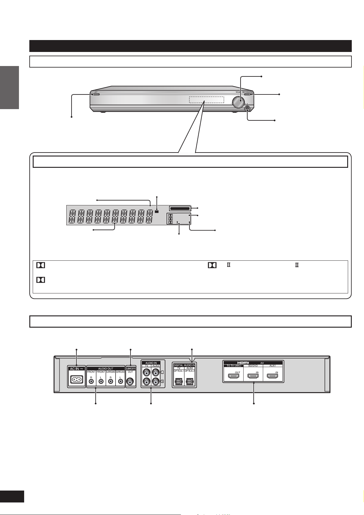
Control guide
Main unit (Control box)
Front view
Before use
For adjusting volume
(➜ page 18)
[INPUT SELECTOR]
switch (➜ page 18)
Standby/on switch (8) (➜ pages 15, 18)
Press to switch the unit from on to standby mode
or vice versa. In standby mode, the unit is still
consuming a small amount of power.
Control guide
Display
When PCM signal is being input
or the input signal setting is fi xed
to PCM (➜ page 26)
General display
DIGITAL : Dolby Digital sources
DTS : DTS sources
VS : When Dolby Virtual Speaker is working
SFC : When SFC mode is being used
Wireless Link display
(Displayed when wireless speakers are properly operating.)
(➜ page 16)
PCM
W
DIGITAL INPUT
DIGITAL DTS
VS
SFC
MIX
PL
When input signal is digital
When the input signal setting is fi xed to DTS
(➜ page 26)
Digital surround signal/Sound fi eld
(➜ below, page 19)
PL : When Dolby Pro Logic decoder is being
For connecting
headphones (➜ page 27)
When the sound fi eld effect is off by
pressing [–SETUP, OFF] (➜ page 19) or
when using headphones (➜ page 27)
used (When using Dolby Virtual Speaker
for 2-channel stereo source)
6
VQT2R71
Rear view
AC input terminal
(➜ page 14)
Audio output terminal
(➜ below)
• The audio output terminals can be used when you do not use the wireless function and play back on other speakers via an
external amplifier. Use commercially available monaural audio cables (monaural mini plug/pin plug) to connect to audio input
terminals of an external amplifier channel by channel.
Subwoofer output
terminal (➜ page 13)
(➜ pages 10 to 13)
Digital audio input terminal (➜ pages 10 to 12, 21)
HDMI terminal (➜ pages 10, 11, 13, 21)Audio input terminal
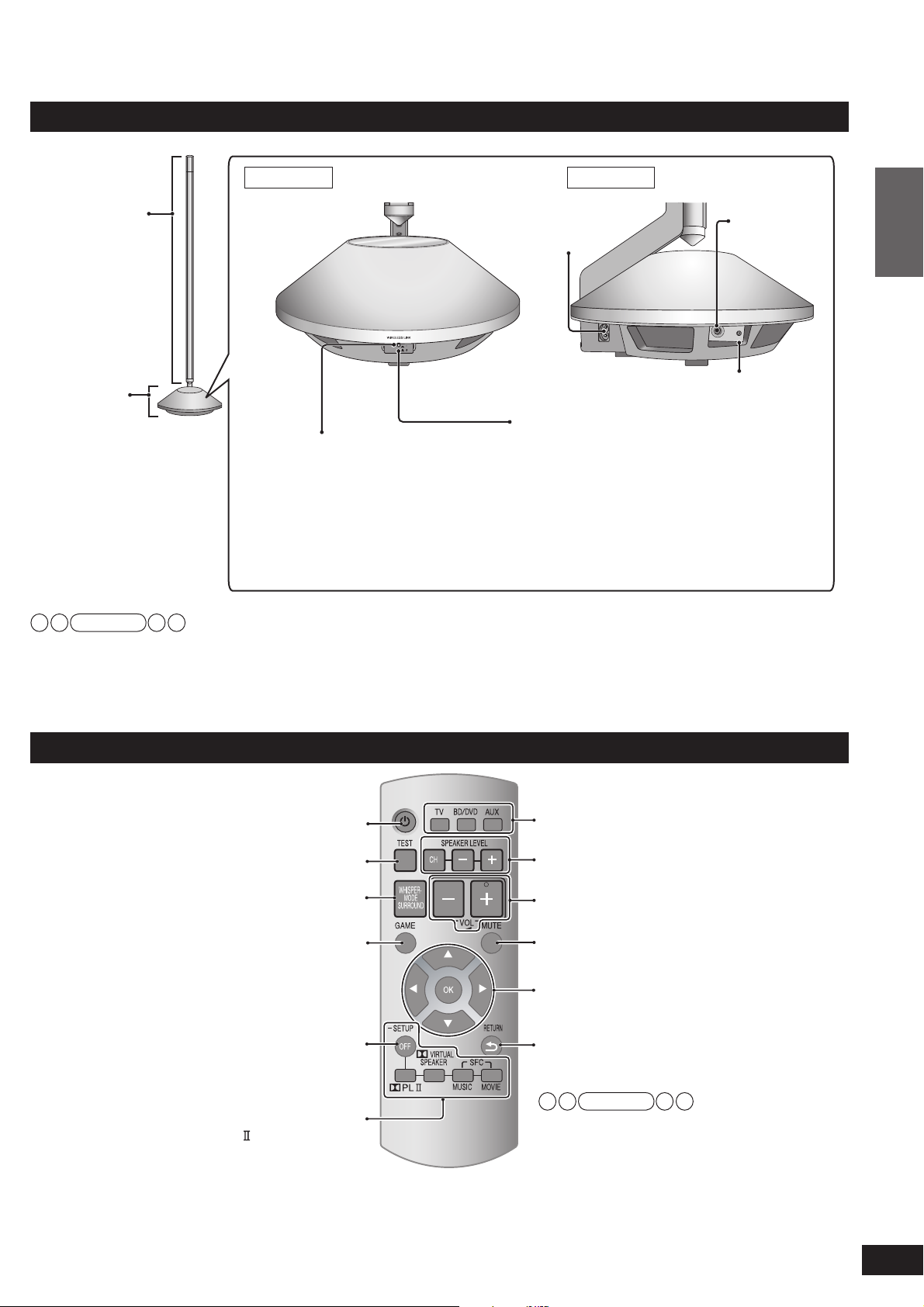
Speaker (with built-in amplifi er)
Front view Side view
Pole
(mid-high part)
AC input terminal
(➜ page 14)
AC IN
㨪
TEST
TEST
terminal
Before use
ID
Base
(woofer part)
ID switch
Unit on/off button (k I l ^) (➜ page 15)
[WIRELESS LINK] indicator
(➜ page 15)
When the unit is connected to the
AC mains supply, this indicator
lights red in standby mode and
lights green when the unit is turned
Use this button to turn the unit on and off.
(off): The unit is in standby mode.
l
(on): The unit is on.
k
The unit is still using a small amount of
power in the standby. Standby uses less
power.
on.
Note
TEST terminal: This is used to check the product operation status. Only used in factory. Do not insert a foreign object.
ID switch: This is used to check the product operation status and not used regularly.
Remote control
Standby/on button (➜ page 18)
Input selector (➜ pages 18, 26)
Control guide
Test signal output (➜ pages 16, 23)
For using “WHISPER-MODE SURROUND”
(➜ page 22)
For using “GAME” (➜ page 22)
For entering setup mode
(➜ pages 11, 17, 22 to 26)
For selecting or cancelling
Dolby Virtual Speaker,
Dolby Pro Logic and SFC mode
(➜ page 19)
For adjusting speaker output
(➜ pages 22, 23)
For adjusting the volume (➜ page 18)
Muting (➜ page 22)
For adjusting/activating settings
(➜ pages 11, 17, 22 to 26)
For returning to the previous menu
(➜ pages 11, 17, 22 to 26)
Note
For remote control buttons used for speaker
setting, see pages 15 to 17.
7
VQT2R71
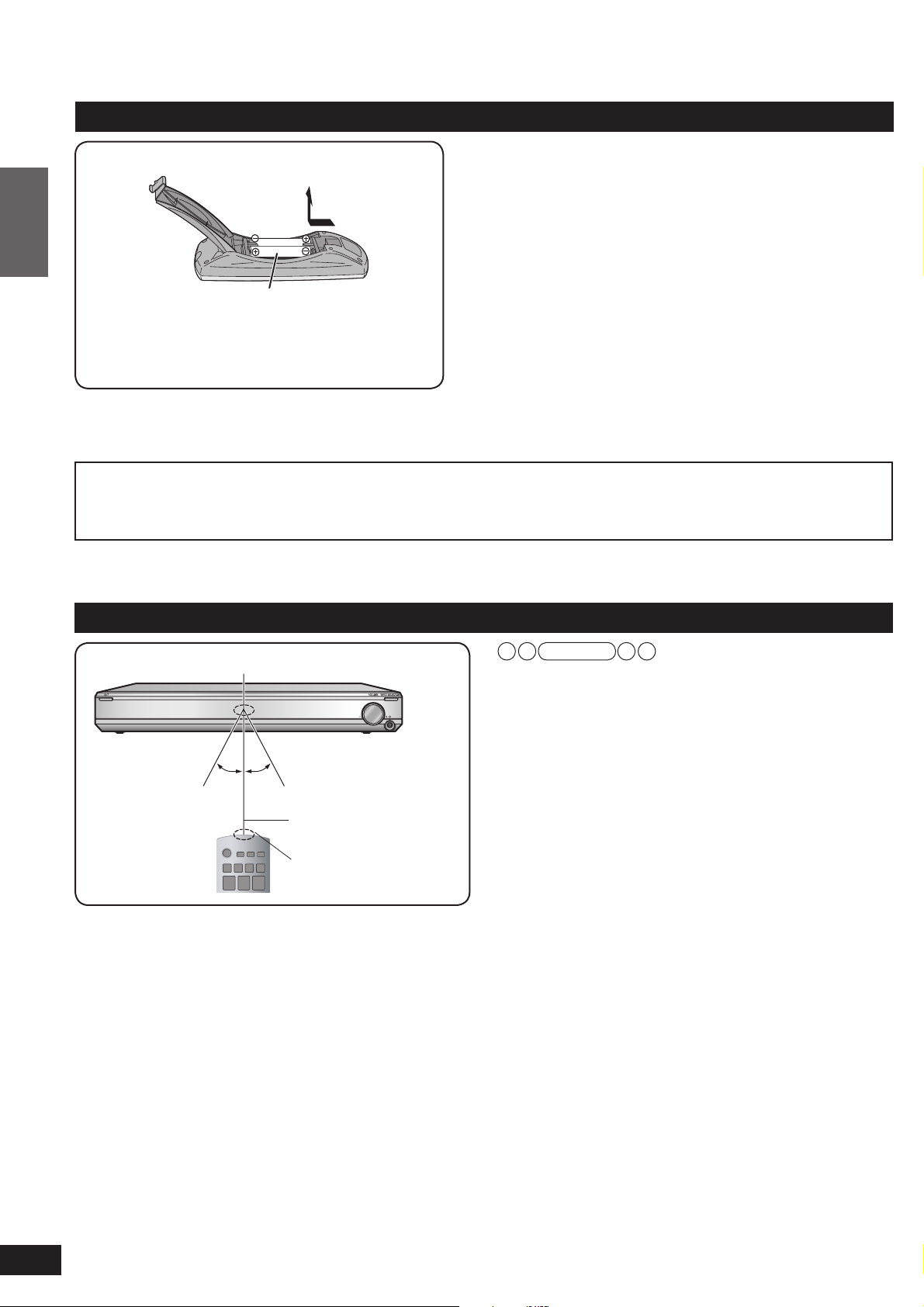
Remote control preparation
Inserting the batteries
Press on the tab to open.
Before use
(R6/LR6, AA)
Insert so the poles (( and )) match those in the
remote control.
Use manganese batteries or alkaline batteries.
CAUTION
Remote control preparation
Danger of explosion if battery is incorrectly replaced. Replace only with the same or equivalent type recommended by
the manufacturer. Dispose of used batteries according to the manufacturer’s instructions.
• Do not mix old and new batteries.
• Do not use different types of batteries at the same time.
• Do not take apart or short circuit.
• Do not attempt to recharge alkaline or manganese batteries.
• Do not use batteries if the covering has been peeled off.
• Do not heat or expose to fl ame.
• Do not leave the batteries in an automobile exposed to direct
sunlight for a long period of time with doors and windows
closed.
Mishandling of batteries can cause electrolyte leakage which
can severely damage the remote control.
Remove the batteries if the remote control is not going to be
used for a long period of time. Store them in a cool, dark place.
Using the remote control
Main unit
Remote control signal sensor
Within approx. 7 meters
Approx.
Approx.
30º
at the front (The
30º
remote controlling
range varies according
to the angles.)
Transmission
window
Note
• Do not place an object between the signal sensor and
the remote control.
• Do not expose the signal sensor to the direct sunlight or
the strong light of a fl uorescent lamp.
• Keep the transmission window and the system’s sensor
free from dust.
8
VQT2R71
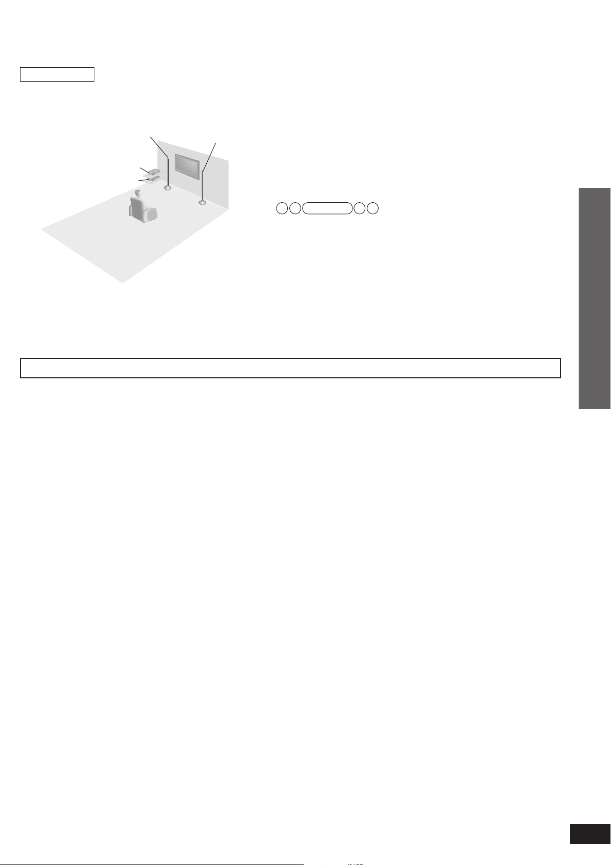
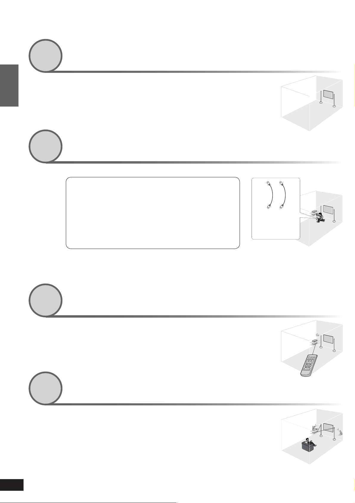
Installation
Setup example
• Aim the front face (with Panasonic logo) of each
speaker at the listening-viewing position for setting.
Front speaker
(left)
Connected equipment
Main unit
Front speaker
(right)
There is no positional distinction for each speaker
before setting.
Make sure to place the speakers on a fl at, stable
surface so there is no danger of them falling over.
When carrying speakers, hold the pole and base
parts (➜ page 7).
The speakers of this system are not magnetically
shielded.
Do not install this system near a CRT-based
television.
Note
• Make sure the base parts are not covered by cloth such as a
curtain.
• Before attaching the leg cushion (supplied) on the base parts
to prevent tilt or rattle on the fl oor, make sure there are no
people in the surrounding area.
• If the main unit is placed at the height of 50 cm or below from
the fl oor, the radio waves reach smaller range.
• Do not install other equipment directly on or under the main
unit.
• “Installing surround speakers” (➜ page 16).
Connection
Wireless functions
As this system uses a frequency band of 2.4 GHz, the radio waves may be interrupted by an obstacle. Depending on the surrounding
environment (i.e. radio wave interruption from outside, etc.) or the building structure where this system is used (i.e. wall that easily
refl ects radio waves, etc.), sounds may be cut or noise may occur.
Install this system properly paying attention to the following descriptions.
Equipment certifi cation
As this system received Technical Conditions compliance certifi cation based on the Radio Law, the wireless station license is not
required. However, if you do the following actions to this system, you may be punished by law.
• Disassemble or refurbish
Restrictions for use
• Domestic use only.
• Use this system in the same room.
Do not place an obstacle between the main unit and speakers. Do not put things on the main unit.
Radio waves from this system reach maximum range of 15 m in the same room. If there is an obstacle between the main unit and
speakers or the main unit is placed at the height of 50 cm or below from the fl oor, the radio waves reach smaller range.
Keep this system away from equipment that generates radio wave interference.
If the following equipment is located near the system, install this system away from such equipment.
• Bluetooth, OA devices, telephone, etc.: approx. 3 m or more
• Microwave oven, wireless LAN compatible devices: approx. 3 m or more
This system is designed to automatically avoid radio wave interference with such household equipment. If radio wave interference
occurs, the Wireless Link display (➜ page 16) may blink, the sounds from speakers may be interrupted or noise may occur.
These phenomena occur when this system selects a proper frequency. These are not malfunctions.
Keep this system away from metal objects that tend to refl ect radio waves.
If there are metal objects or furniture in the room where this system is installed, radio waves tend to be refl ected. Depending on the
listening-viewing position, sounds may be interrupted or noise may occur. These symptoms may be remedied by slightly moving this
system’s position.
Note that radio waves tend to be refl ected also when this system is installed in rooms with a lot of activity.
Installation
9
VQT2R71
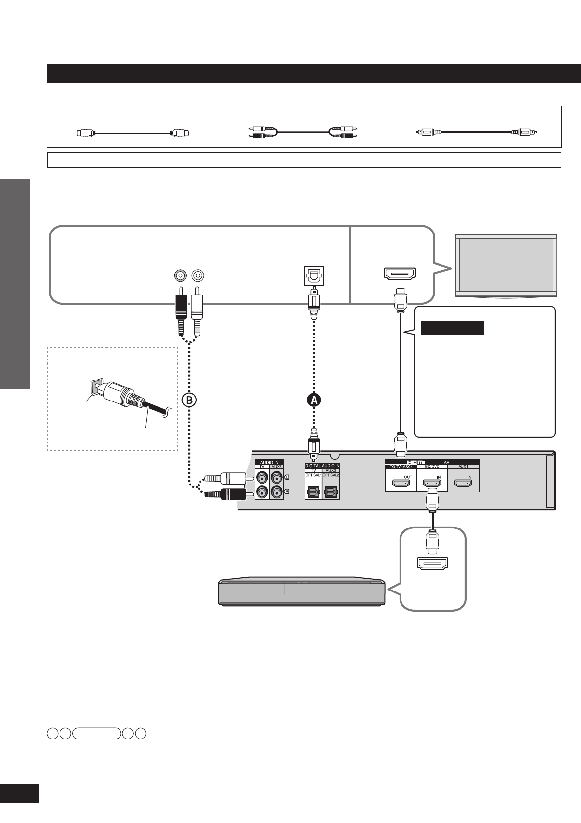
Home Theater connections
Basic connections
Connection cable
HDMI cable (not supplied) Stereo phono cable (not supplied) Optical fi bre cable (not supplied)
Connecting equipment with HDMI terminal (TV, DVD recorder, etc.)
Easy connection using ARC (Audio Return Channel) (➜ below): The conventional setting has required 2 cables
to connect this system and a TV: HDMI cable and optical fi bre or stereo phono cable. Now, with the ARC
technology, all you need is 1 HDMI cable to connect to an ARC compatible TV.
The recommended HDMI cable is ARC compatible.
This connection is
necessary to connect
with TV incompatible
with ARC.
In order to enjoy TV
sounds.
Audio out
R L
Digital audio
out (optical)
HDMI
input
TV
Connection
Connecting the optical
fi bre cable
Insert the cable
so its shape fi ts
correctly into
the terminal.
ARC (Audio Return Channel)
This function was added to HDMI
Ver.1.4.
Home Theater connections
This sends digital audio signals
from the HDMI input terminal of
the TV, etc. to the HDMI output
terminal of this system.
• For ARC compatibility of the
connected TV, see operating
instructions of the TV.
Do not bend!
If connection A
is not possible,
make connection
. When both are
B
already connected,
connection A
takes priority over
connection B.
Blu-ray Disc player/
DVD recorder, STB, etc.
Make sure to connect to
TO TV (ARC) .
When connecting with the ARC
compatible TV, connect the
[TO TV (ARC)] terminal of this
system and the HDMI input
terminal (ARC compatible) of TV.
(If the TV has ARC compatible
and incompatible terminals,
connect to the ARC compatible
HDMI input terminal.)
Main unit
HDMI
Video/Audio
out
10
VQT2R71
HDMI cable notes
• It is recommended that you use Panasonic’s HDMI cables.
• Please use High Speed HDMI Cables that have the HDMI logo (as shown on the cover).
• Using the High Speed HDMI cable is recommended for viewing HD picture (1080p).
Enjoying only with TV speaker
• When image equipment such as TV and Blu-ray Disc player/DVD recorder, etc. is connected to HDMI terminal (➜ above, page 13)
of this system, images/audio signals from the Blu-ray Disc player/DVD recorder, etc. go through this system and are transmitted to
TV even if this system is turned off using the standby/on button of this system. (Standby through function) This is convenient to
enjoy only with TV speaker.
Note
When you turn this system off using the standby/on button of this system, the audio/video signals from equipment connected to
HDMI input are output through the television, even if you have set input on this system to anything other than HDMI input (“BD/DVD ”
or “AUX 1 ”) before turning off this system. (The selector returns to the previous setting when you turn this system on again.)
When equipment is connected to both BD/DVD IN terminal and AUX1 IN terminal, images/audio signals of equipment whose input is
lastly selected are output.
 Loading...