

Page 1
I
RMS
10%
1
1
100
Total
Total
half
Input
TV,
S/N
BD/DVD,
Input
TV,
Tone
BASS
TREBLE
Digital
Optical
Coaxial
HDMI
HDMI
This
I
Home Theater Audio System
SC-HTR310P
Colour
(K)... Black Type
ORDER NO. MD0808009CE
A6
Specification
Amplifier Section
output power of each channel driven
total harmonic distortion
kHz Front CH 70 W per channel (4 Ω)
kHz Center CH 70 W per channel (4 Ω)
Hz Subwoofer CH 90 W per channel (3 Ω)
RMS output power 300 W
harmonic distortion
power at 1kHz (Front CH) 0.5 % (4 Ω )
sensitivity
AUX 3 450 mV, IHF’66
at rated power (4 Ω)
TV, AUX 1, AUX 2 80 dB
impedance
AUX 3 47 kΩ
controls
50Hz,+6dBto-6dB
20 kHz, +6 dB to -6 dB
input
Input 1
Output 1
system supports “HDAVI Control 1” function.
General
Power supply AC 120V, 60 Hz
Power consumption
Main set 68 W
Standby (HDMI ON) 0.7 W
Standby (HDMI OFF) 0.3 W
I Rack System
INCLUDING SPEAKER
Dimensions (W x H x D) 1300 mm x 444 mm x 458 mm
Mass approx. 50 kg
* Mass is a Completed (AMP, Speaker Unit inc)
Maximum Loading Weight 80 kg
I Speaker System
FRONT (L/R) 1-Way 1 Speaker System
6.5 cm Cone Type Full Range x1
CENTER 1-Way 1 Speaker System
2
SUBWOOFER 1-Way 2 Speaker System
1
Notes :
1. Specifications are subject to change without notice.
2. Total harmonic distortion is measured by the digital spectrum
analyser.
6.5 cm Cone Type Full Range x1
13 cm Cone Type Woofer x2
(Bass Reflect)
(Bass Reflect)
(Bass Reflect)
© 2008 Matsushita Electric Industrial Co. Ltd.. All
rights reserved. Unauthorized copying and
distribution is a violation of law.
Page 2
SC-HTR310P
CONTENTS
Page Page
1 Safety Precaution s 3
2 Prevention of Electro Static Discharge (ESD) to
Electrostatically Sensitive (ES) Devices
3 Handling the Lead free Solder
4 Operating Procedures
5 Self Diagnosis Display Function
6 HDMI Checking Method
7 Assembling and Disassembling
8 Service Position
9 Voltage Measurement & Waveform Chart
10 Wiring Connection Diagram 103
11 Block Diagram
6
12 Notes Of Schematic Diagram
7
13 Schematic Diagram
14 Printed Circuit Board Diagrams
8
25
15 Illustration of IC’s, Transistors and Diodes
29
16 Terminal Function of IC’s
17 Exploded Views
31
84
18 Replacement Parts List
92
105
109
111
127
135
136
137
141
2
Page 3
SC-HTR310P
1 Safety Precautions
1.1. General Guidelines
1. When servicing, observe the original lead dress. If a short circuit is found, replace all parts which have been overheated or
damaged by the short circuit.
2. After servicing, ensure that all the protective devices such as insulation barriers, insulation papers shields are properly installed.
3. After servicing, check for leakage current checks to prevent from being exposed to shock hazards.
(This “Safety Precaution” is applied only in U.S.A.)
1. Before servicing, unplug the power cord to prevent an electric shock.
2. When replacing parts, use only manufacturer’s recommended components for safety.
3. Check the condition of the power cord. Replace if wear or damage is evident.
4. After servicing, be sure to restore the lead dress, insulation barriers, insulation papers, shields, etc.
5. Before returning the serviced equipment to the customer, be sure to make the following insulation resistance test to prevent the
customer from being exposed to a shock hazard.
1.1.1. Leakage Current Cold Check
1. Unplug the AC cord and connect a jumper between the two prongs on the plug.
2. Using an ohmmeter measure the resistance value, between the jumpered AC plug and each expose d metallic cabine t part on
the equipment such as screwheads, connectors, control shafts, etc. When the exposed metallic part has a return path to the
chassis, the reading should be between 1MΩ and 5.2Ω.
When the exposed metal does not have a return path to the chassis, the reading must be
.
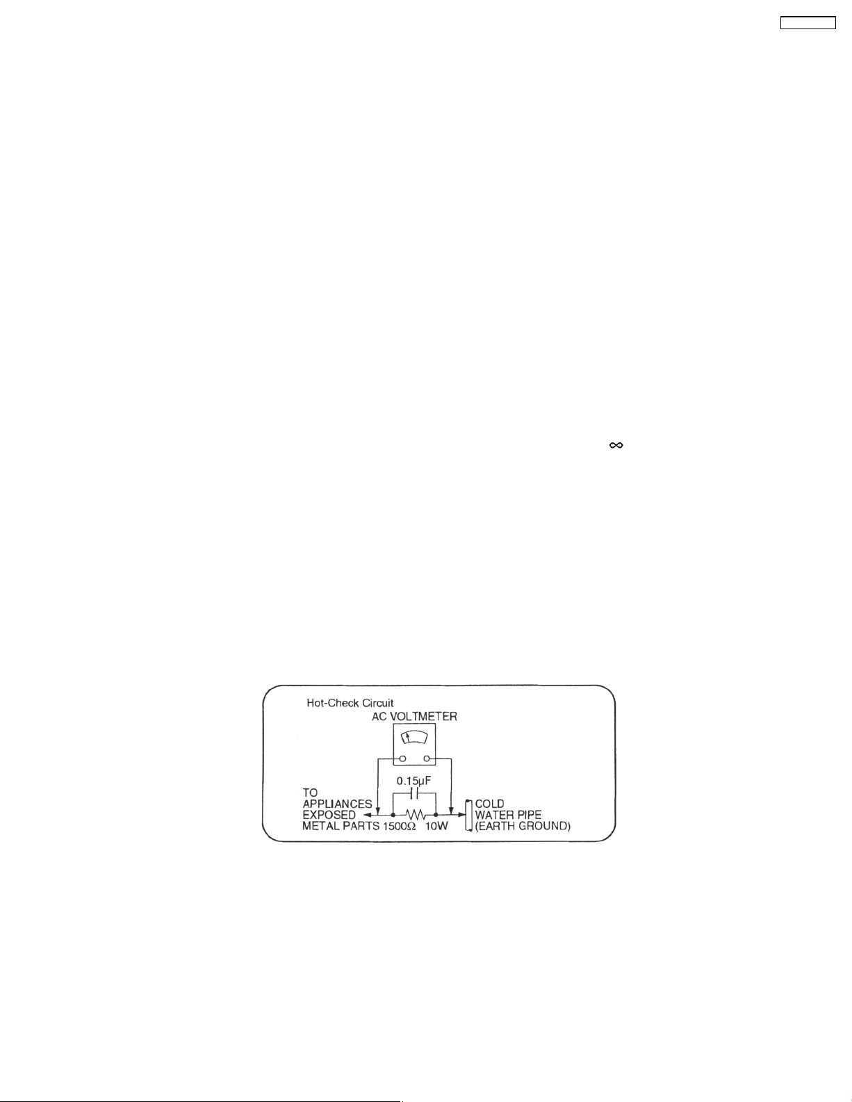
1.1.2. Leakage Current Hot Check
1. Plug the AC cord directly into the AC outlet. Do not use an isolatio n transformer for this check.
2. Connect a 1.5kΩ, 10 watts resistor, in parallel with a 0.15µF capacitors, between each exposed metallic part on the set and a
good earth ground such as a water pipe, as shown in Figure 1.
3. Use an AC voltmeter, with 1000 ohms/volt or more sensitivity, to measure the potential across the resistor.
4. Check each exposed metallic part, and measure the voltage at each point.
5. Reverse the AC plug in the AC outlet and repeat each of the above measurements.
6. The potential at any point should not exceed 0.75 volts RMS. A leakage current tester (Simpson Model 229 or equivalent) may
be used to make the hot checks, leakage current must not exceed 1/2 milliamp. should the measurement is outside of the limits
specified, there is a possibility of a shock hazard, and the equipment should be repaired and re-checked before it is returned
to the customer.
Fig. 1
3
Page 4
SC-HTR310P
1.2. Before Repair and Adjustment
Disconnect AC power, discharge ac capacitors C5712, C5808, C5805, C5813, C5816, C5824, C5517 , C5516, C5508, C5509,
C5510, C5511, C5512 and C5513 through a 10Ω, 1W resistor to ground.
DO NOT SHORT-CIRCUIT DIRECTLY (with a screwdriver blade, for instance), as this may destroy solid state devices.
After repairs are completed, restore power gradually using a variac, to avoid overcurrent.
• Current consumption at AC 120 V, 60 Hz in NO SIGNAL mode (at volume minimum) should be 200 ~ 800 mA.
1.3. Protection Circuitry
The protection circuitry may have operated if either of the following conditions are noticed:
• No sound is heard when the power is turned on.
• Sound stops during a performance.
The function of this circuitry is to prevent circuitry damage if, for example, the positive and negative speaker connec tion wires are
"shorted", or if speaker systems with an impedance less than the indicated rated impedance of the amplifier are used.
If this occurs, follow the procedure outlines below:
1. Turn off the power.
2. Determine the cause of the problem and correct it.
3. Turn on the power once again after one minute.
Note:
When the protection circuitry functions, the unit will not operate unless the power is first turned off and then on again.
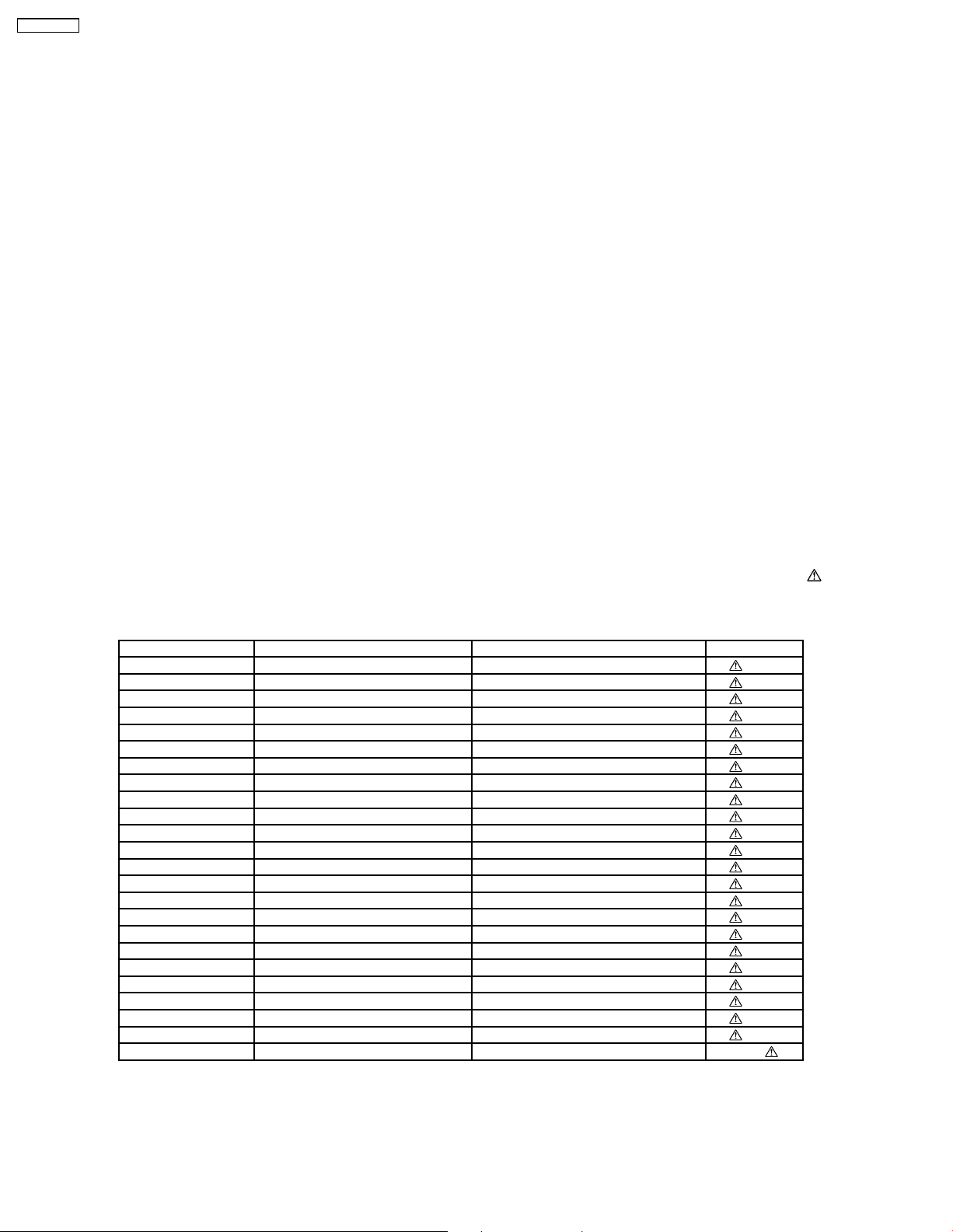
1.4. Safety Part Information
Safety Parts List:
There are special components used in this equipment which are important for safety.These parts are marked by
Schematic Diagrams & Replacement Parts List. It is essential that these critical parts should be replaced with manufacturer’s
specified parts to prevent shock, fire or other hazards. Do not modify the original design without permission of manufacturer.
Table 1
Reference No. Part No. Part Name & Description Remarks
8 REXX0640-J BLACK WIRE [M]
9 REXX0641-J RED WIRE [M]
14 RKMX0141B-S1 TOP CABINET [M]
15 RGR0383D-C REAR PANEL [M]
A2 K2CB2CB00021 AC CORD [M]
A6 RFA2903 TOP GLASS ACCESSORY [M]
A8 RXQ1607 PREPARED GLASS DOOR ASSY L [M]
A9 RXQ1608 PREPARED GLASS DOOR ASSY R [M]
DZ5701 ERZV10V511CS ZENER [M]
L5701 ELF15N035AN LINE FILTER [M]
L5702 ELF22V020A LINE FILTER [M]
T701 G4D1A0000117 SW TRANSFORMER [M]
T5701 ETS42BM1A1AC TRANSFO RMER [M]
T5751 ETS19AB281AG BACKUP TRANSFORMER [M]
PC5701 B3PBA0000402 PHOTO COUPLER [M]
PC5720 B3PBA0000402 PHOTO COUPLER [M]
PC5799 B3PBA0000402 PHOTO COUPLER [M]
F1 K5D802APA008 FUSE [M]
IP701 K5H5012A0010 IC PROTECTOR [M]
IP702 K5H302100004 IC PROTECTOR [M]
TH5701 D4CAA2R20001 THERMISTOR [M]
TH5860 D4CC11040013 THERMISTOR [M]
P5701 K2AB2B000011 AC INLET [M]
PCB5 REPX0676N SMPS P.C.B. / AC INLET P.C.B. [M] (RTL)
in the
4
Page 5

1.5. Caution for fuse replacement
SC-HTR310P
5
Page 6

SC-HTR310P
2 Prevention of Electro Static Discharge (ESD) to
Electrostatically Sensitive (ES) Devices
Some semiconductor (solid state) devices can be damaged easily by electricity. Such components commonly are called
Electrostatically Sensitive (ES) Devices. Examples of typical ES devices are integrated circuits and some field-effect transistors and
semiconductor “chip” components. The following techniques should be used to help reduce the incidence of component damage
caused by electro static discharge (ESD).
1. Immediately before handlin g any semiconducto r component or semiconductor-equiped assembly, drain off any ESD on your
body by touching a known earth ground. Alternatively, obtain and wear a commercially available discharging ESD wrist strap,
which should be removed for potential shock reasons prior to applying power to the unit under test.
2. After removing an electrical assembly equiped with ES devices, place the assembly on a conductive surface such as aluminium
foil, to prevent electrostatic charge build up or exposure of the assembly.
3. Use only a grounded-tip soldering iron to solder or unsolder ES devices.
4. Use only an anti-static solder remover device. Some solder removal devices not classified as “anti-static (ESD protected)” can
generate electrical charge to damage ES devices.
5. Do not use freon-propelled chemicals. These can generate electrical charges sufficie nt to damage ES devices.
6. Do not remove a replacement ES device from its protective package until immediately before you are ready to install it. (Most
replacement ES devices are packaged with leads electrically shorted together by conductive foam, aluminium foil or
comparable conduc tive material).
7. Immediately before removing the protective material from the leads of a replacement ES device, touch the protective material
to the chassis or circuit assembly into which the device will be installe d.
Caution
Be sure no power is applied to the chassis or circuit, and observe all other safety precautions.
8. Minimize body motions when handling unpackaged replacement ES devices. (Otherwise harmless motion such as the brushing
together of your clothes fabric or the lifting of your foot from a carpeted floor can generate static electricity (ESD) sufficie nt to
damage an ES device).
6
Page 7
SC-HTR310P
3 Handling the Lead free Solder
3.1. General description about Lead Free Solder (PbF)
The lead free solder has been used in the mounting process of all electrical components on the printed circuit boards used for this
equipment in considering the globally environmental conservation.
The normal solder is the alloy of tin (Sn) and lead (Pb). On the other hand, the lead free solder is the alloy mainly consists of tin
(Sn), silver (Ag) and Copper (Cu), and the melting point of the lead free solder is higher approx.30 degrees C (86°F) more than that
of the normal solder.
Definition of PCB Lead Free Solder being used
The letter of “PbF” is printed either foil side or component s side on the PCB using the lead free solder.
(See right figure)
Service caution for repair work using Lead Free Solder (PbF)
• The lead free solder has to be used when repairing the equipment for which the lead free solder is used.
(Definition: The letter of “PbF” is printed on the PCB using the lead free solder.)
• To put lead free solder, it should be well molten and mixed with the original lead free solder.
• Remove the remaining lead free solder on the PCB cleanly for soldering of the new IC.
• Since the melting point of the lead free solder is higher than that of the normal lead solder, it takes the longer time to melt
the lead free solder.
• Use the soldering iron (more than 70W) equipped with the temperature control after setting the temperature at 350±30
degrees C (662±86°F).
Recommended Lead Free Solder (Service Parts Route.)
• The following 3 types of lead free solder are available through the service parts route.
RFKZ03D01K-----------(0.3mm 100g Reel)
RFKZ06D01K-----------(0.6mm 100g Reel)
RFKZ10D01K-----------(1.0mm 100g Reel)
Note
* Ingredient: Tin (Sn), 96.5%, Silver (Ag) 3.0%, Copper (Cu) 0.5%, Cobalt (Co) / Germanium (Ge) 0.1 to 0.3%
7
Page 8
SC-HTR310P
4 Operating Procedures
4.1. Control guide
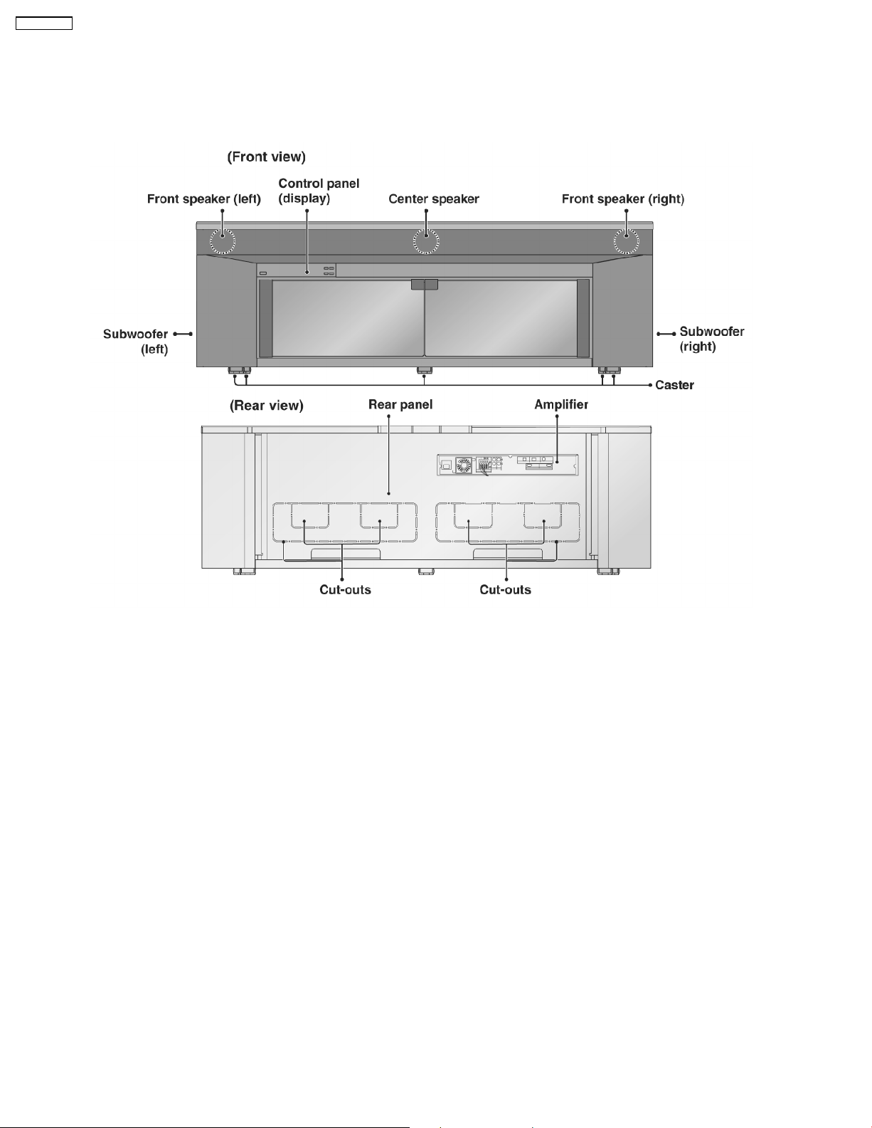
4.1.1. This system
8
Page 9
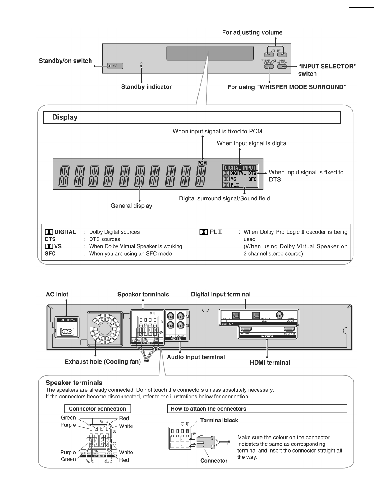
4.1.2. Control panel
SC-HTR310P
4.1.3. Amplifier
9
Page 10
SC-HTR310P
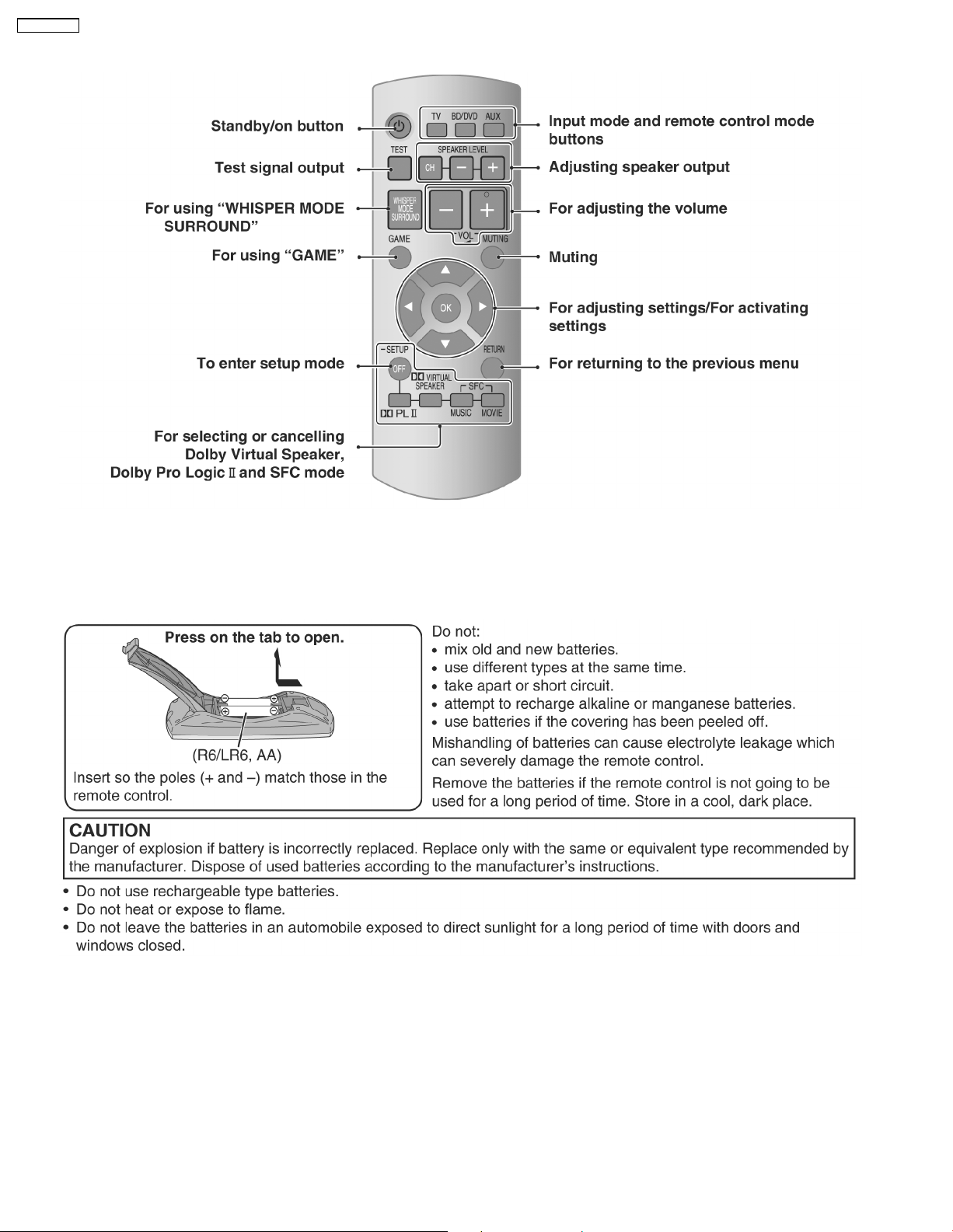
4.1.4. Remote control
4.2. Remote control preparation
4.2.1. Inserting the batteries
10
Page 11
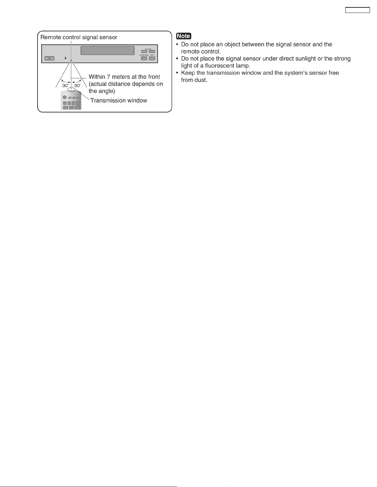
4.2.2. Using the remote control
SC-HTR310P
11
Page 12
SC-HTR310P
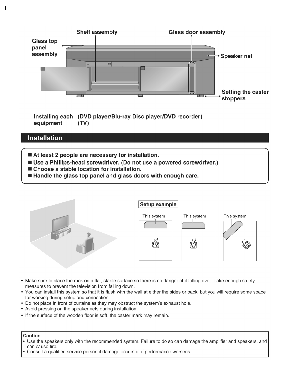
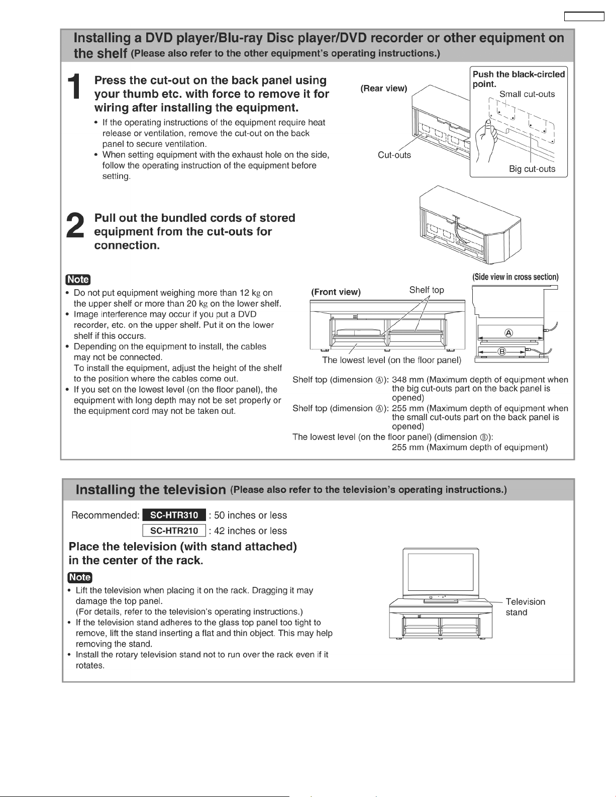
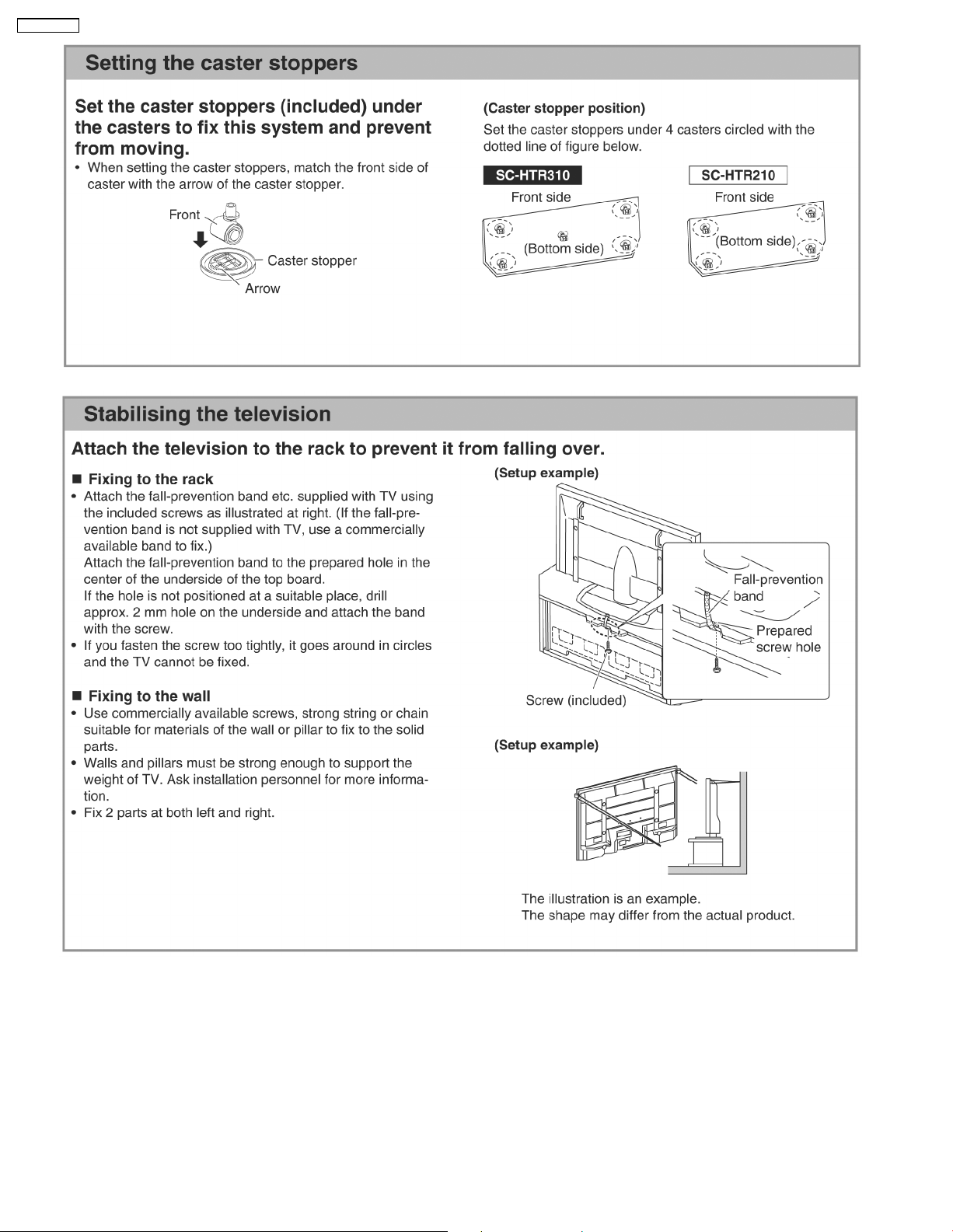
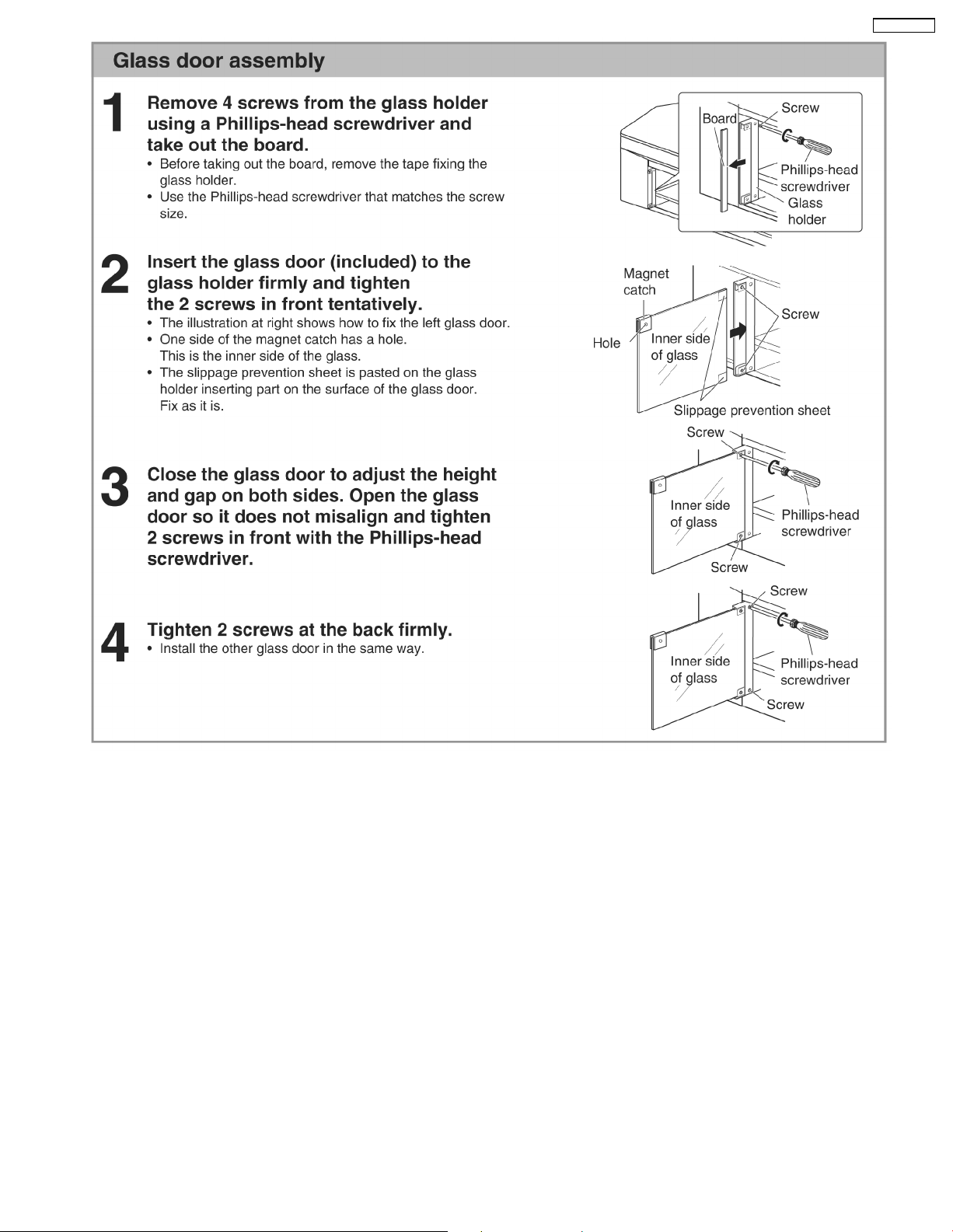
4.3. Installing and assembling the rack
12
Page 13
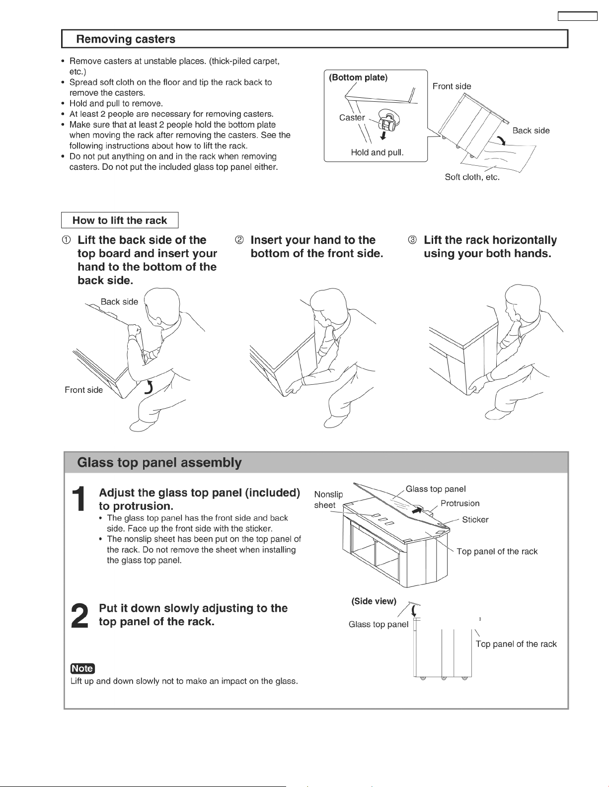
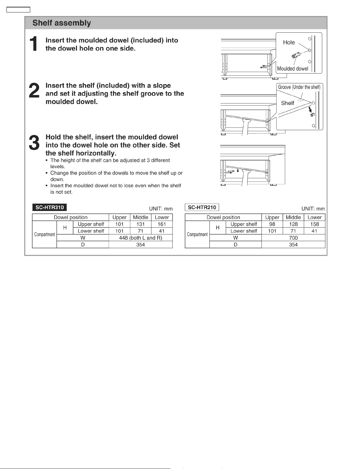
SC-HTR310P
13
Page 14
SC-HTR310P
14
Page 15
SC-HTR310P
15
Page 16
SC-HTR310P
16
Page 17
SC-HTR310P
17
Page 18
SC-HTR310P
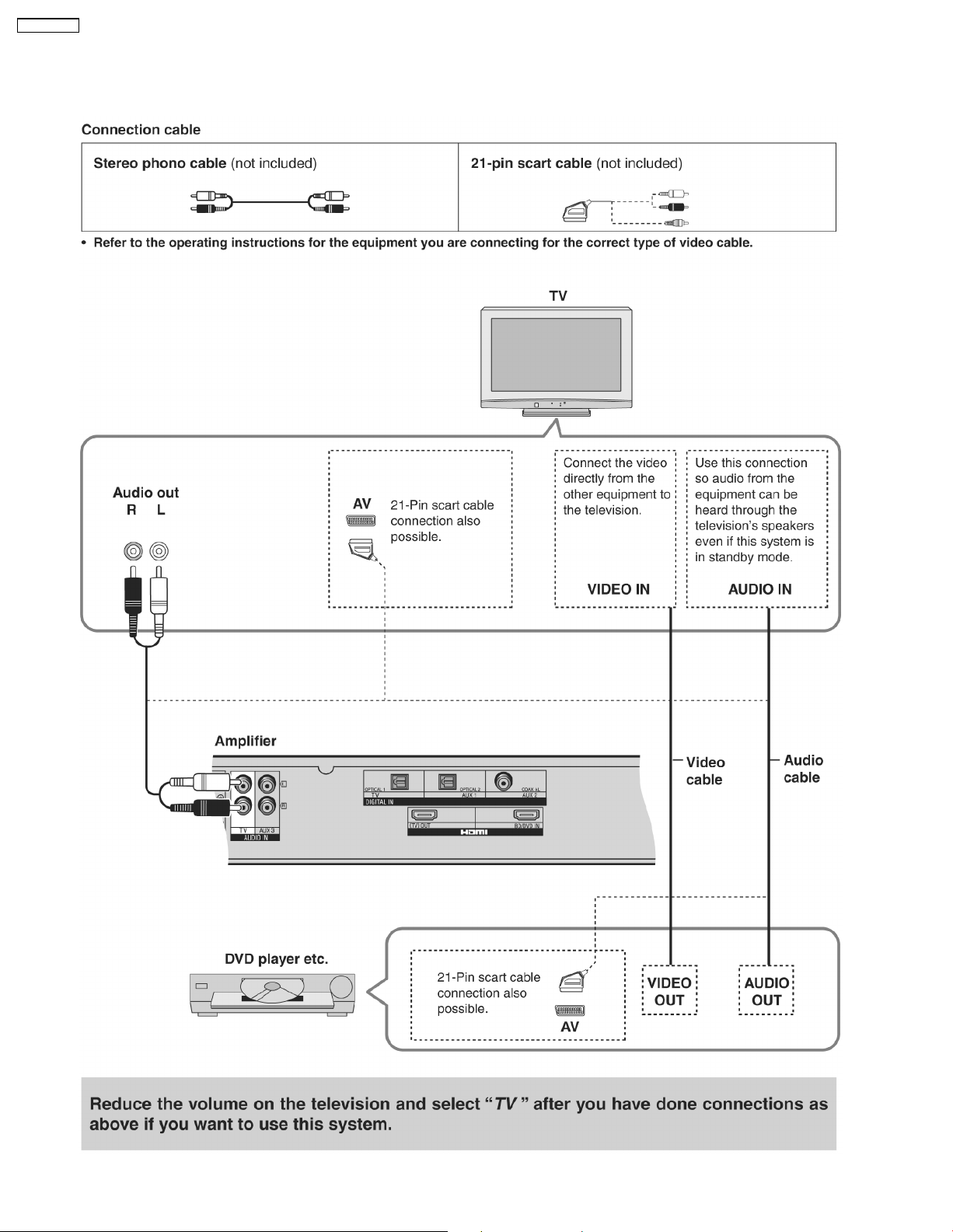
4.4. Home Theater connections
4.4.1. Basic connections
18
Page 19
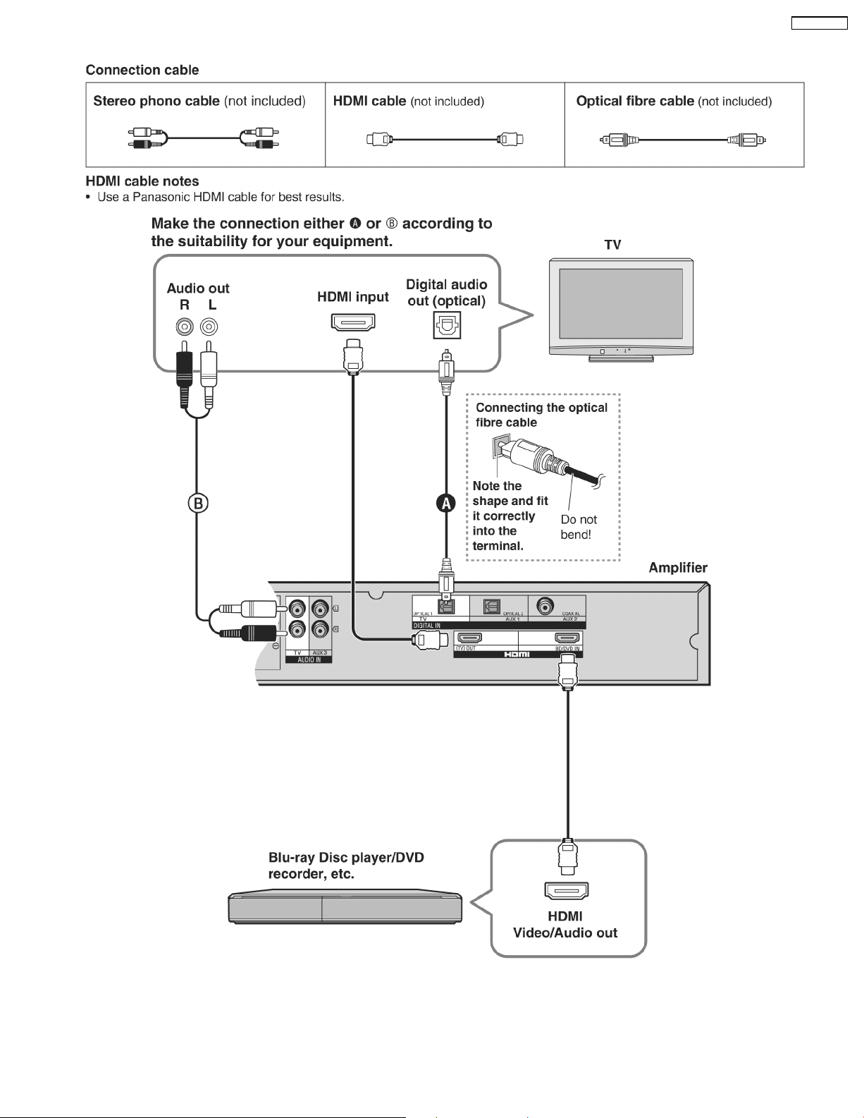
4.4.2. Connecting equipment with HDMI terminal (TV, DVD recorder, etc.)
SC-HTR310P
19
Page 20
SC-HTR310P
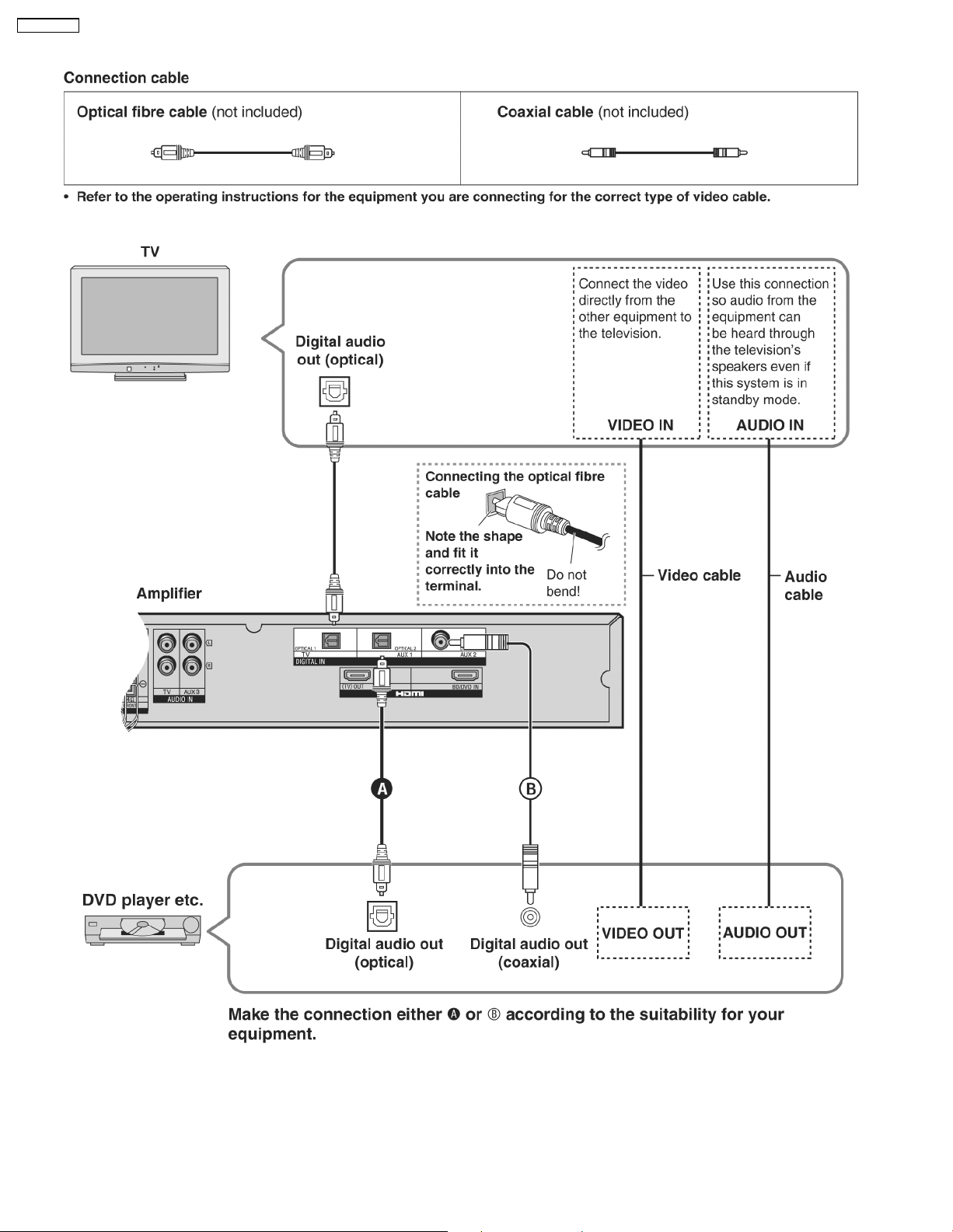
4.4.3. Connecting with digital terminal-mouted equipment
20
Page 21
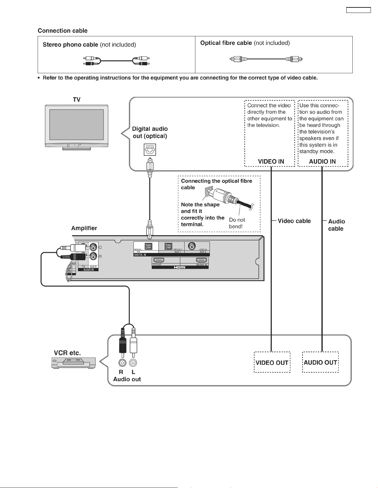
4.4.4. Connecting with VCR
SC-HTR310P
21
Page 22
SC-HTR310P
4.5. Other connections
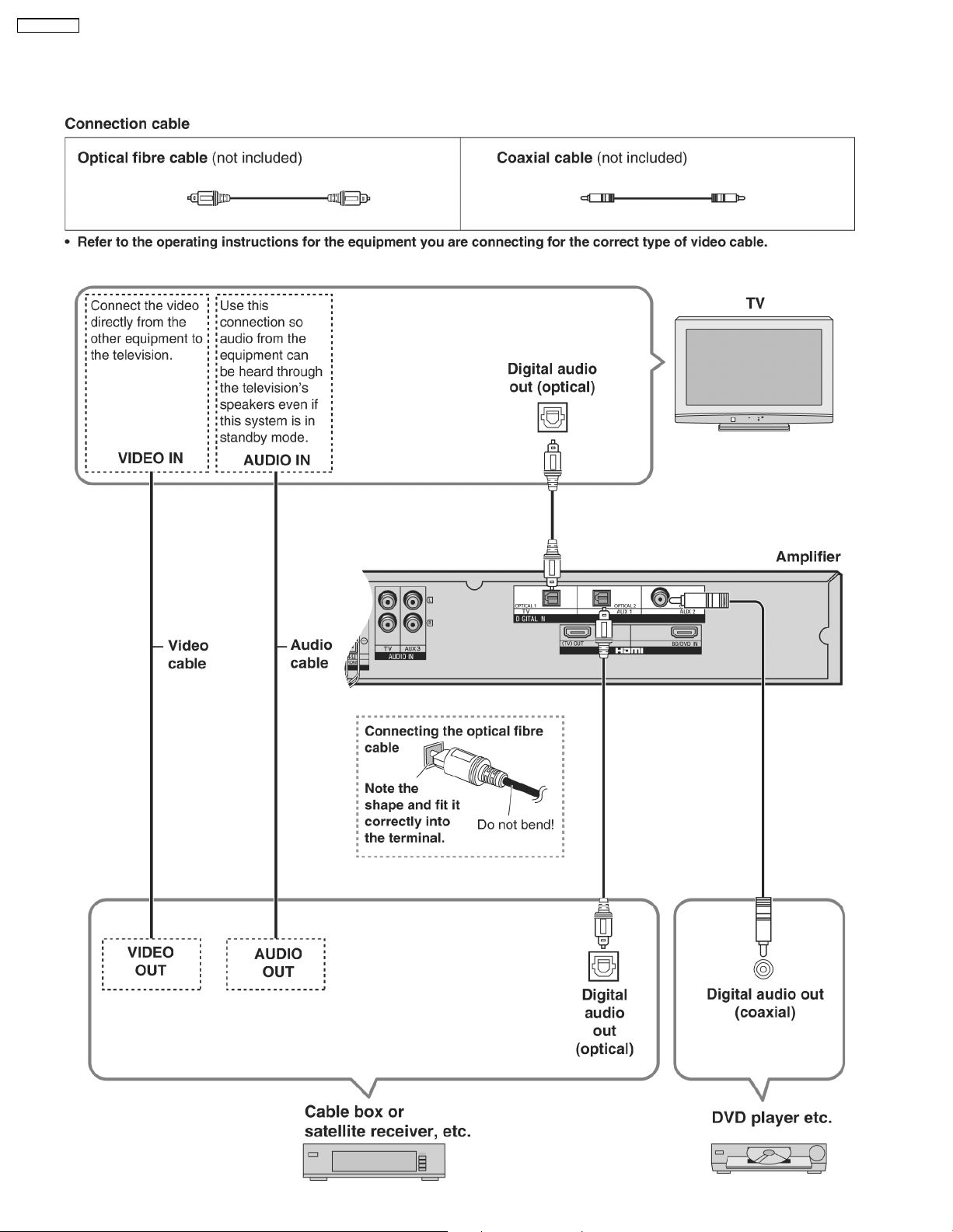
4.5.1. Connecting a set top box (cable or satellite)
22
Page 23
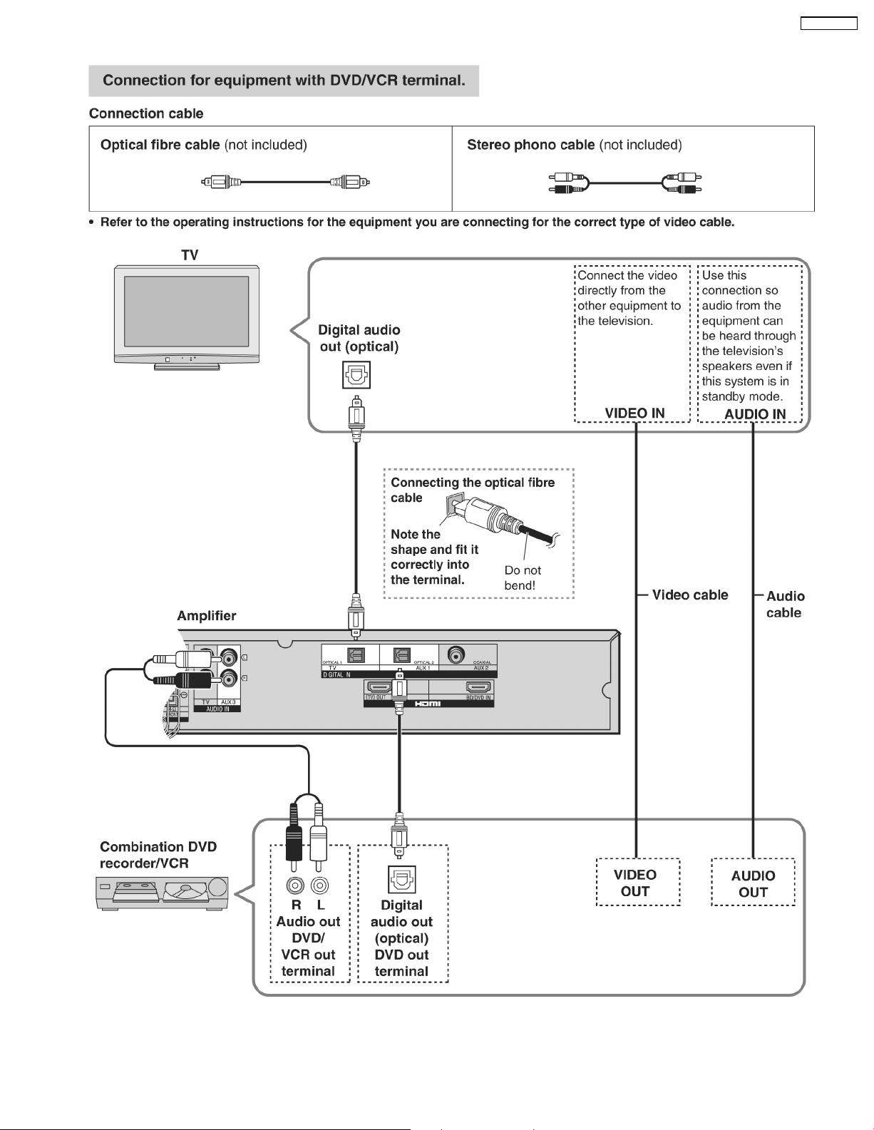
4.5.2. Connecting a combination DVD recorder/VCR
SC-HTR310P
23
Page 24
SC-HTR310P
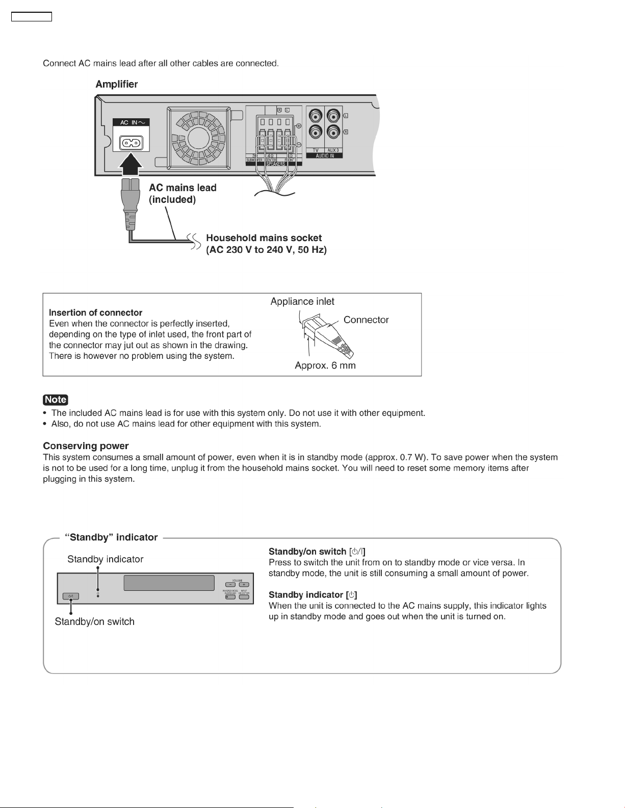
4.6. AC mains supply connection
24
Page 25
5 Self Diagnosis Display Function
SC-HTR310P
This unit is equipped with the self diagnosis display function,
during servicing.
which alarms faulty operation with error code. Use this function
5.1. Automatically Displayed Error Codes
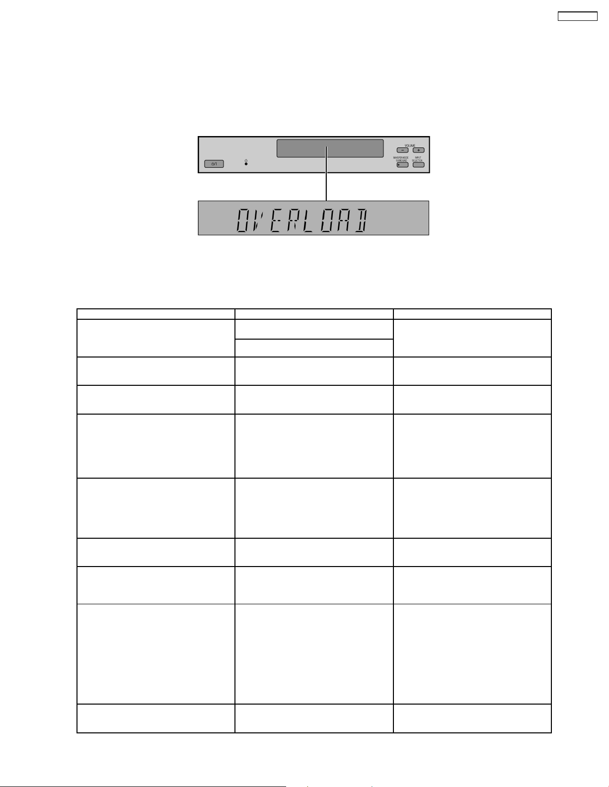
An error code automatically appears on the display (LCD) when faulty operation is detected. Refer to Fig. 5.1.
Fig. 5.1
5.2. Display Details
Refer to the following table.
LCD display Symptom Cause and Remedy
OVERLOAD Speaker short, amplifier failure, electrical
FANLOCK Fan stopped Failure fan and fan control circuits. Check
F70 Communication error between sub micro-
F76 When the power is turned on, the unit
Remote 2
Remote 1
U70-1-1 — The equipment connected by the HDMI
U70-1-2 — The system is receiving video signals that
U70-3 — A problem has occurred with the HDMI
NOT POSSIBLE FOR THIS INPUT
SOURCE
(Scrolling)
overload etc.
Humidity protection activated
processor and its peripheral LSI
power automatically turns off; the power
cannot be turned on.
— Set the same remote control code for this
— You cannot use Dolby Virtual Speaker,
Speaker short and failure in power
amplifier, pre-amplifier circuits. Check for
faulty parts and replace with new parts if
necessary.
for faulty parts and replace with new parts
if necessary.
Failure sub-micro processor and its
peripherals LSI. Check for faulty parts and
replace with new parts if necessary.
Failure in the power circuit system of the
unit. This may happen when the direct
current electricity is supplied to speaker
terminals. Check that the speaker wires
are not shorted (bare wire touching each
other) or that the unit is in a hot
enviroment without proper ventillation.
system and remote control.
• If “REMOTE 2” is displayed, set remote
control code to “2”.
• If “REMOTE 1” is displayed, set remote
control code to “1”.
cable is not compatible with this system’s
copyright protection technology.
are incompatible with it through HDMI
connection. Check the settings of the
connected equipment.
connection. Try the following to correct the
problem. Consult your dealer if the error
code remains on the display.
• Turn the connected equipment off and
on again.
• Disconnect the HDMI cable then
reconnect it.
• Do not connect more than 2 equipment
in series to the output of this system.
Dolby Pro Logic II and SFC for dual
sounds.
25
Page 26

SC-HTR310P
LCD display Symptom Cause and Remedy
NOT POSSIBLE FOR THIS PCM
SOURCE
(Scrolling)
— You cannot use Dolby Virtual Speaker,
Dolby Pro Logic and SFC effect with PCM
signals with sampling frequency over 48
kHz.
SFC is not available for multi-channel
LPCM signal.
26
Page 27
SC-HTR310P
5.3. Activating Self Diagnosis Function (Servicing Mode)
This mode can be used during servicing.
1. Plug the AC adapter to the power source. Press and hold down the [VOL +] button and the [VOL -] button, and then press the
[POWER] button at the same time.
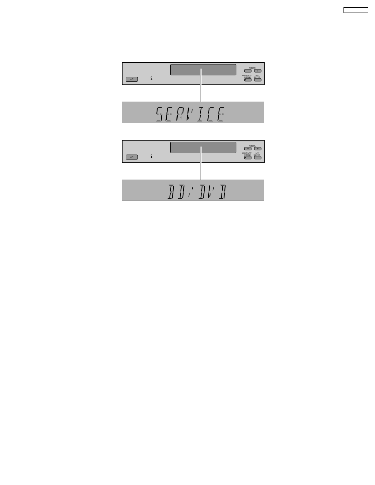
2. The message, [SERVICE] appears on the display for three seconds, and then it will display the following. Refer to Fig. 5.2.
Fig. 5.2
3. To confirm the µP software version: When [VOL +] button is pressed, [M--- ****] is display ed [---] is current main micon version;
[****] is current checksum. If no ROM correction, [NO] is display ed.
When [VOL -] is pressed, display [H***], [***] is current version of HDMI micon.
27
Page 28
SC-HTR310P
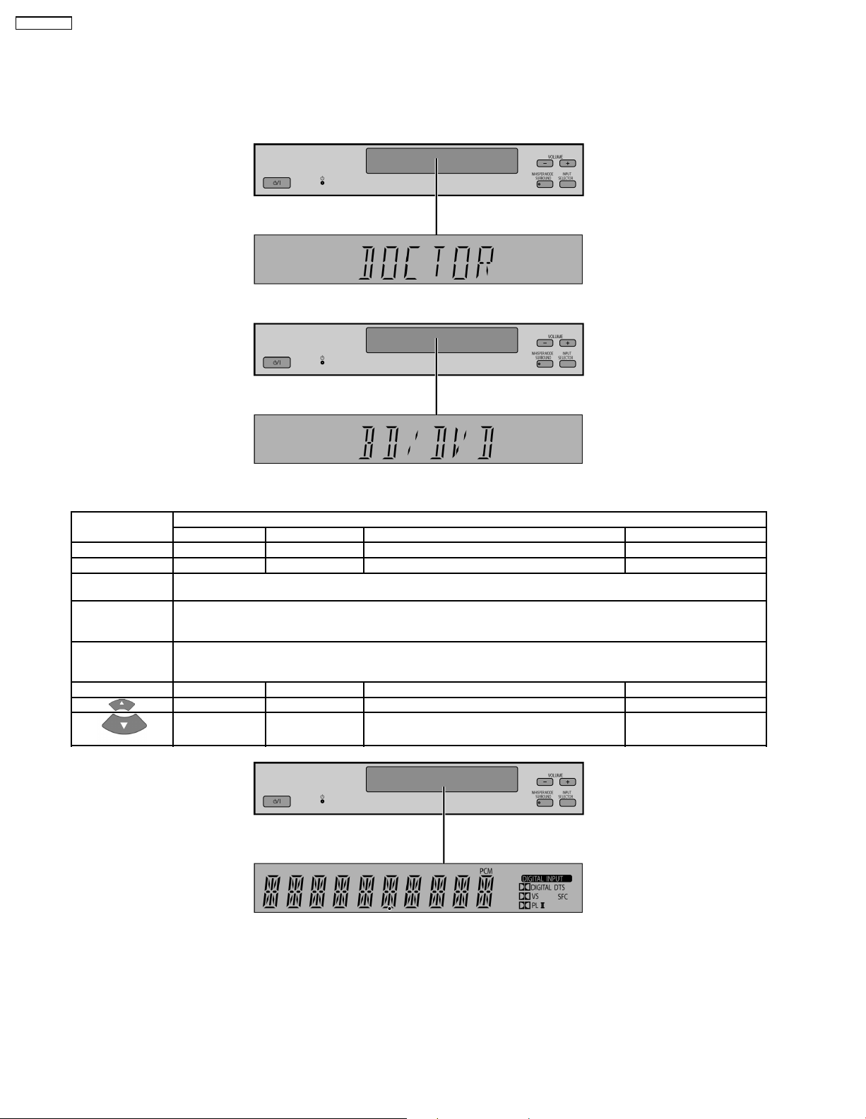
5.4. Activating Self Diagnosis Function (Doctor Mode)
This mode can be used during servicing.
1. Plug the AC adapter to the power source. Press and hold down the [INPUT SELECTOR] button and the [VOL +] button, and
then press the [POWER] button at the same time.
2. The message, “_DOCTOR_” appears on the display for three seconds, and then it will display the following. Refer to Fig. 5.3.
Fig. 5.3
3. Doctor mode function at some remote control codes as below table.
Remote Control Test Mode Function and settings
Selector Sound Mode other settings Vol/Tone
OK TV STEREO Digital (OPT 1 ) -48dB/0dB
SFC MUSIC AUX 1 STEREO Digital (OPT 2 ) -48dB/0dB
MUTING All indicators of FL are displayed. All LED are off. Refer to Fig. 5.4.
Volume Up Check Main µP software version.
Volume Down Check HDMI uP software Version.
TEST AUX2 (Analog) - All CH Output Mode -18dB/0dB
Note : After this setting, only ‘POWER’ button or ‘Checker Command’ code by the remote control can be entered.
Display [M---- ****], [----] is current version; **** is current checksum. If no ROM correction, [NO] is displayed.
Volume is still increased but not displayed.
Display [H---- ^^^^^], [----] is current version.
Volume is still increased but not displayed.
TV STEREO Balance is set to leftmost. -18dB/0dB
TV STEREO Balance is set to rightmost. -18dB/0dB
5.5. Returning to Normal Display
Press the [POWER] button on the unit to exit the function. The
power is turned off.
Fig. 5.4
28
Page 29
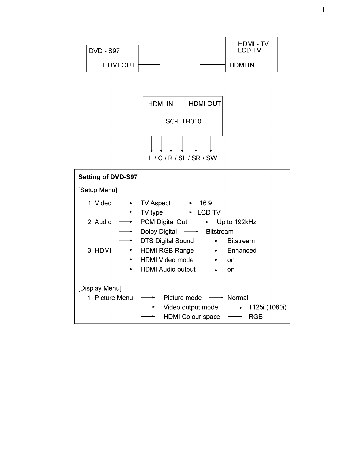
6 HDMI Checking Method
1. Connection of HDMI system
SC-HTR310P
2. Check of HDMI Sound
a. Using the [DVD AUDIO TEST DISC V-612] and DVD-VIDEO disc with Dolby Digital signal.
b. [DVD AUDIO TEST DISC V-612] - Track No. 92 (96kHz, 5.1ch). Track No. 40 (Zero) Check the Level and Noise, output from
L / C / R / SL / SR / SW / speaker or pin.
c. [DVD AUDIO TEST DISC V-612] - Track No. 7 (192kHz, 2ch)
if this source can be reproduced, it is OK.
3. Check of HDMI Picture
a. The picture quality of TV is checked by watching that using [DVD TEST DISK S-20] or DVD disc with the colour bar signal.
b. [DVD TEST DISK S-20] - Track No. 2 (Flag of the rising sun)
[Colour bar disc] - Colour bar signal.
c. Make on DVD Setup Picture
Comfirmed that there are neither distortion nor a noise on the screen.
• If it is a picture quality equal when DVD was connec ted directly to TV, it is OK
29
Page 30

SC-HTR310P
1. Connect directly DVD player to TV.
2. Connect DVD player to set then connect it to TV.
3. Do the comparison for (1) and (2) if same, it is OK.
30
Page 31

SC-HTR310P
7 Assembling and Disassembling
7.1. Caution
“ATTENTION SERVICER”
Be careful when disassembling and servicing.
Some chassis components may have sharp edges.
Special Note:
1. This section describes the disassembly procedures for all the major printed circuit boards and main components.
2. Before the disassembly process was carried out, do take special note that all safety precautions are to be carried out.
(Ensure that no AC power supply is connected during disassembling.)
3. For assembly after operation checks or replacement, reverse the respective procedures.
Special reassembly procedures are described only when required.
4. Do take note of the locators on each printed circuit board during reassembling procedures.
5. The Switch Regulator IC may have high temperature after prolonged use.
6. Use caution when removing the top cabinet and avoid touching heat sinks located in the unit.
7. Select items from the following index when checks or replacement are required.
• Disassembly of Front Net Frame
• Disassembly of Front ornament (L)
• Disassembly of Side Board Assy (L)
• Disassembly of Sub Woofer Left (SP2)
• Disassembly of Front ornament (R)
• Disassembly of Side Board Assy (R)
• Disassembly of Sub Woofer Right (SP2)
• Disassembly of Centre speaker (SP1)
• Disassembly of Front Left speaker (SP1)
• Disassembly of Front Right speaker (SP1)
• Disassembly of Front Baffle Assembly
• Disassembly of Panel P.C.B.
• Disassembly of Amplifier Unit
• Disassembly of Glass Ornament (L)
• Disassembly of Glass Ornament (R)
• Disassembly of Top Cabinet
• Disassembly of Rear Cabinet
• Disassembly of Front Cabinet
• Disassembly of AC Inlet P.C.B.
• Disassembly of Main P.C.B.
• Disassembly of D-Amp P.C.B.
• Replacement of Audio Digital Power Amp IC (IC5000)
• Replacement of Audio Digital Power Amp IC (IC5300)
• Disassembly of SMPS P.C.B.
• Replacement of Switching Regulator IC (IC5701)
• Replacement of Diode (D5702)
• Replacement of Diode (D5801)
31
Page 32

SC-HTR310P
• Replacement of Diode (D5802)
• Replacement of Diode (D5803)
• Disassembly of HDMI P.C.B.
• Disassembly of DSP P.C.B.
32
Page 33

SC-HTR310P
7.2. Disassembly flow chart
The following chart is the procedure for disassembling the casing and inside parts for internal inspection when carrying out the
servicing.
To assemble the unit, reverse the steps shown in the chart below.
33
Page 34

SC-HTR310P
7.3. Main Parts Location Diagram (Amplifier unit)
34
Page 35

7.4. Main Parts Location Diagram (Rack Cabinet)
SC-HTR310P
35
Page 36

SC-HTR310P
7.5. Disassembly of Front Net Frame
Step 1 : Insert Steel Rule in between Front Net Frame and Rack Cabinet as arrow shown.
Step 2 : Slightly push the Steel Rule as arrow shown to push out the Front Net Frame.
Step 3 : Apply light force to remove the Front Net Frame in order of sequences (from 1 to 9).
36
Page 37

7.6. Disassembly of Front ornament (L)
• Follow the (Step 1) - (Step 3) of item 7.5.
SC-HTR310P
Step 1 : Remove 1 screw.
Step 2 : Insert the screwdriver with Cloth in between the Rack Cabinet and the Front Ornament (L), and slightly push the
screwdriver as arrow shown to release the Bosses in order of sequence.
Caution : Wrap the screwdriver with a cloth.
Step 3 : Remove the Front Ornament (L) as arrow shown.
37
Page 38

SC-HTR310P
7.7. Disassembly of Side Board Assy (L)
• Follow the (Step 1) - (Step 3) of item 7.5.
• Follow the (Step 1) - (Step 3) of item 7.6.
Step 1 : Pull the Side Board Assy (L) to release the bosses as arrow shown.
Step 2 : Remove the Side Board Assy (L) as arrow shown.
Caution : Take extra care for the guide holes on the cabinet during removal and assembly of the side board assy (L).
38
Page 39

7.8. Disassembly of Sub Woofer Left (SP2)
• Follow the (Step 1) - (Step 3) of item 7.5.
• Follow the (Step 1) - (Step 3) of item 7.6.
• Follow the (Step 1) - (Step 2) of item 7.7.
Step 1 : Remove 2 screws and remove Catch Holder.
SC-HTR310P
Step 2 : Remove 4 screws.
Step 3 : Detach the Black (+) and Red (-) speaker wires.
Step 4 : Remove the Sub Woofer Left (SP2) as arrow shown.
39
Page 40

SC-HTR310P
7.9. Disassembly of Front ornament (R)
• Follow the (Step 1) - (Step 3) of item 7.5.
Step 1 : Remove 1 screw.
Step 2 : Insert the screwdriver with Cloth in between the Rack Cabinet and the Front Ornament (R), and slightly push the
screwdriver as arrow shown to release the Bosses in order of sequence.
Caution : Wrap the screwdriver with a cloth.
Step 3 : Remove the Front Ornament (R) as arrow shown.
40
Page 41

7.10. Disassembly of Side Board Assy (R)
• Follow the (Step 1) - (Step 3) of item 7.5.
• Follow the (Step 1) - (Step 3) of item 7.9.
Step 1 : Pull the Side Board Assy (R) to release the Bosses as arrow shown.
SC-HTR310P
Step 2 : Remove the Side Board Assy (R) as arrow shown.
Caution : Take extra care for the guide holes on the cabinet during removal and assembly of the side board assy (R).
41
Page 42

SC-HTR310P
7.11. Disassembly of Sub Woofer Right (SP2)
• Follow the (Step 1) - (Step 3) of item 7.5.
• Follow the (Step 1) - (Step 3) of item 7.9.
• Follow the (Step 1) - (Step 2) of item 7.10.
Step 1 : Remove 2 screws and remove Catch Holder.
Step 2 : Remove 4 screws.
Step 3 : Detach the Black (+) and Red (-) speaker wires.
Step 4 : Remove the Sub Woofer Right (SP2) as arrow shown.
42
Page 43

7.12. Disassembly of Centre speaker (SP1)
• Follow the (Step 1) - (Step 3) of item 7.5.
Step 1 : Remove 3 screws.
SC-HTR310P
Step 2 : Prepare a Box.
Step 3 : Remove the Centre speaker unit and place on the box.
Step 4 : Pull out the Eva Cushio n partially.
43
Page 44

SC-HTR310P
Step 5 : Remove 6 screws.
Step 6 : Remove the Centre speaker panel as arrow shown.
Step 7 : Detach the White (+) and Blue (-) speaker wires.
Step 8 : Remove 4 screws.
Step 9 : Remove the Centre speaker (SP1) as arrow shown.
44
Page 45

Caution : During reassembling procedures, ensure the cable are properly dresse d.
SC-HTR310P
45
Page 46

SC-HTR310P
7.13. Disassembly of Front Left speaker (SP1)
• Follow the (Step 1) - (Step 3) of item 7.5.
• Follow the (Step 1) - (Step 3) of item 7.6.
Step 1 : Remove 3 screws.
Step 2 : Prepare a Box.
Step 3 : Remove the front Speaker unit and place on the box.
Step 4 : Remove 4 screws.
Step 5 : Remove the Front speaker panel as arrow shown.
46
Page 47

Step 6 : Detach the Yellow (+) and Black (-) speaker wires.
Step 7 : Remove 4 screws.
Step 8 : Remove the Front Left speaker (SP1) as arrow shown.
Caution : During reassembling procedures, ensure the cable are properly dresse d.
SC-HTR310P
47
Page 48

SC-HTR310P
7.14. Disassembly of Front Right speaker (SP1)
• Follow the (Step 1) - (Step 3) of item 7.5.
• Follow the (Step 1) - (Step 3) of item 7.9.
Step 1 : Remove 3 screws.
Step 2 : Prepare a Box.
Step 3 : Remove the Front speaker unit and place on the box.
Step 4 : Remove 4 scews.
48
Page 49

Step 5 : Remove the Front speaker panel as arrow shown.
Step 6 : Detach the Grey (+) and Blue (-) speaker wires.
SC-HTR310P
Step 7 : Remove 4 screws.
Step 8 : Remove the Front Right speaker (SP1) as arrow shown.
Caution : During reassembling procedures, ensure the cable are properly dresse d.
49
Page 50

SC-HTR310P
7.15. Disassembly of Front Baffle Assembly
• Follow the (Step 1) - (Step 3) of item 7.5.
Step 1 : Push the Glass door holder.
Step 2 : Open the Glass door as arrow shown.
Step 3 : Tilt the Shelf board (R) up slightly and remove it as arrow shown.
Note : Repeat the same step for the Shelf board (L).
50
Page 51

Step 4 : Detach cable at connector (CN601 and CN602) on Panel P.C.B..
SC-HTR310P
Step 5 : Remove 8 screws.
51
Page 52

SC-HTR310P
Step 6 : Prepare a Box.
Step 7 : Remove the Front Baffle Assembly as arrow shown and place it on the Box.
52
Page 53

7.16. Disassembly of Panel P.C.B.
• Follow the (Step 1) - (Step 3) of item 7.5.
• Follow the (Step 1) - (Step 7) of item 7.15.
Step 1 : Remove 2 screws.
SC-HTR310P
Step 2 : Remove 2 screws.
Step 3 : Remove the Front Panel as arrow shown.
Step 4 : Remove 2 screws.
Step 5 : Release 2 catches.
53
Page 54

SC-HTR310P
Caution : Take extra care for the locator on the Panel P.C.B. during removal and assembly of the Panel P.C.B..
Step 6 : Remove the Panel P.C.B. as arrow shown.
54
Page 55

7.17. Disassembly of Amplifier Unit
• Follow the (Step 1) - (Step 3) of item 7.5.
• Follow the (Step 1) - (Step 5) of item 7.15.
SC-HTR310P
Step 1 : Remove 2 screws.
Step 2 : Prepare a Box.
Step 3 : Remove the Front Baffle Assembly as arrow shown and place it on the Box.
55
Page 56

SC-HTR310P
Step 4 : Remove 4 screws.
Step 5 : Lift up the Main Set a bit and remove the Amp Fixtures as arrow shown.
56
Page 57

SC-HTR310P
Step 6 : Remove the main set as arrow shown.
Caution : During reassembling procedures, ensure the cable are properly dresse d.
57
Page 58

SC-HTR310P
7.18. Disassembly of Glass Ornament (L)
• Follow the (Step 1) - (Step 3) of item 7.5.
• Follow the (Step 1) - (Step 7) of item 7.15.
Step 1 : Loosen the Screws for removing the Glass door.
Step 2 : Remove the Glass door as arrow shown.
Step 3 : Remove 2 screws.
58
Page 59

SC-HTR310P
Step 4 : Remove the Glass ornament (L) as arrow shown.
Caution : Be careful of losing the Pivot holder as it may fall off when the Hinge angle (L) removed from the Glass ornament
(L).
59
Page 60

SC-HTR310P
7.19. Disassembly of Glass Ornament (R)
• Follow the (Step 1) - (Step 3) of item 7.5.
• Follow the (Step 1) - (Step 7) of item 7.15.
Step 1 : Loosen the Screws for removing the Glass door.
Step 2 : Remove the Glass door as arrow shown.
Step 3 : Remove 2 screws.
60
Page 61

SC-HTR310P
Step 4 : Remove the Glass ornament (R) as arrow shown.
Caution : Be careful of losing the Pivot holder as it may fall off when the Hinge angle (R) removed from the Glass ornament
(R).
61
Page 62

SC-HTR310P
7.20. Disassembly of Top Cabinet
Step 1 : Remove 4 screws.
7.21. Disassembly of Rear Cabinet
• Follow the (Step 1) - (Step 3) of item 7.20.
Step 1 : Remove 9 screws.
Step 2 : Remove 2 screws.
Step 2 : Remove 6 screws.
Step 3 : Lift up the back part of the Top Cabinet and remove it
as arrow shown.
Step 3 : Remove the Wire Clamper to detach the fan unit
connector (CN5501) on D-Amp P.C.B..
62
Page 63

Step 4 : Detach FFC cable at the connector (CN106) on Main
P.C.B..
Step 5 : Detach FFC cable at the connector (CN2001) on
HDMI P.C.B..
SC-HTR310P
Step 7 : Lift up and remove the HDMI P.C.B. with the chassis
from the Rear Cabinet as arrow shown.
Caution : Take extra care for the catches on the Rear
Cabinet during removal and assembly of the HDMI P.C.B.
(with chassis).
Step 6 : Remove one side of the Rear Cabinet as arrow shown.
Be careful both side guides when removing the rear cabinet.
Step 8 : Remove the Rear Cabinet as arrow shown.
63
Page 64

SC-HTR310P
7.22. Disassembly of Front Cabinet
• Follow the (Step 1) - (Step 3) of item 7.20.
Step 1 : Remove 2 screws.
Step 2 : Remove 1 screw.
Step 3 : Remove the Front Cabinet as arrow shown. Be careful
both side guides and three guides at the bottom when
removing the Front Cabine t.
Caution : Do not exert too much force when releasing the
guides.
64
Page 65

7.23. Disassembly of AC Inlet P.C.B.
• Follow the (Step 1) - (Step 3) of item 7.20.
SC-HTR310P
Step 3 : Remove Bracket as arrow shown.
Step 1 : Remove 1 screw.
Step 2 : Remove 1 screw.
Step 4 : Release the one side of the Rear Cabine t as arrow
shown. Be careful Guide when removing the Rear Cabinet.
65
Page 66

SC-HTR310P
Step 5 : Flip over the AC Inlet P.C.B..
Step 6 : Desolder Black and Red wires.
7.24. Disassembly of Main P.C.B.
• Follow the (Step 1) - (Step 3) of item 7.20.
• Follow the (Step 1) - (Step 3) of item 7.22.
Step 1 : Remove 4 screws.
Caution : Take extra care for the locator on the AC Inlet
P.C.B. during removal and assembly of the AC Inlet P.C.B..
Step 2 : Remove 2 screws.
Step 3 : Detach FFC cable at the connector (CN106, CN222
and CN200) on Main P.C.B..
Step 4 : Detach cable at the connector (CNA781) on HDMI
P.C.B..
Caution : Attach wire to Main P.C.B. with Wire Clamper
during assembly. (Replace a new Wire Clamper after
service)
66
Page 67

Step 5 : Lift up Main P.C.B. and remove it forward as arrow
shown in sequences (from 1-2).
SC-HTR310P
During reassembling procedures, ensure the P.C.B. is
seated properly at the locators.
Step 6 : Detach FFC cable at the connector (CN2201) on
HDMI P.C.B..
Step 7 : Detach cable at the connector (CN5802) on SMPS
P.C.B..
67
Page 68

SC-HTR310P
7.25. Disassembly of D-Amp P.C.B.
• Follow the (Step 1) - (Step 3) of item 7.20.
• Follow the (Step 1) - (Step 3) of item 7.22.
• Follow the (Step 1) - (Step 3) of item 7.23.
• Follow the (Step 1) - (Step 2) of item 7.24.
Step 1 : Detach FFC cable at the connector (CN200) on Main
P.C.B..
Caution : Attach wire to Main P.C.B. with Wire Clamper
during assembly. (Replace a new Wire Clamper after
service)
Step 3 : Remove 2 screws.
Step 4 : Detach cable at the connector (CN5500) on D-Amp
P.C.B..
Step 5 : Remove 3 screws.
Step 2 : Lift up Main P.C.B. and shift over the Heat Sink.
68
Page 69

SC-HTR310P
During reassembling procedures, ensure the P.C.B. is
seated properly at the locators.
Step 6 : Remove the wire clamper to detach the fan unit
connector (CN5501) on D-Amp P.C.B..
Step 7 : Open one side of the Rear Cabinet slightly as arrow
shown. Be careful guide when removing the Rear Cabinet.
Step 8 : Remove D-Amp P.C.B. as arrow shown. Be careful
with the guide.
69
Page 70

SC-HTR310P
7.26. Replacement of Audio Digital
Power Amp IC (IC5000)
• Follow the (Step 1) - (Step 3) of item 7.20.
Step 1 : Cut the 5 connecting points as indicated in the
diagram.
Step 2 : Remove the marked portion from the bottom chassis.
Step 4 : Remove 1 screw.
Step 5 : Remove the TR spring as arrow shown.
Step 6 : Remove the Audio Digital Power Amp IC (IC5000)
from the heat sink unit A.
Step 3 : Desolder pins of the Audio Digital Power Amp IC
(IC5000) on the reverse side of D-Amp P.C.B.
70
Page 71

• Assembly of the Audio Digital Power Amp IC (IC5000)
SC-HTR310P
Step 1 : Fix the Audio Digital Power Amp IC (IC5000) to the
heat sink unit A.
Step 2 : Fix the TR spring as arrow shown.
Step 3 : Screw 1 screw at digital amp IC (IC5000) to the heat
sink unit A.
Step 5 : Position the bottom chassis portion into the curves
according to the diagram shown. (Rotate the part at 180
degrees as compared to its original position.)
Step 6 : Screw 1 screw at the Chassis Portion.
Step 4 : Solder pins of the digital amp IC (IC5000) on the
reverse side of D-Amp P.C.B.
Caution : Ensure pins of the digital amp IC (IC5000) are
properly seated and soldered on D-Amp P.C.B.
71
Page 72

SC-HTR310P
7.27. Replacement of Audio Digital
Power Amp IC (IC5300)
• Follow the (Step 1) - (Step 3) of item 7.20.
Step 1 : Cut the 5 connecting points as indicated in the
diagram.
Step 2 : Remove the marked portion from the bottom chassis.
Step 4 : Remove 1 screw.
Step 5 : Remove the TR spring as arrow shown.
Step 6 : Remove the Audio Digital Power Amp IC (IC5300)
from the heat sink unit A.
Step 3 : Desolder pins of the Audio Digital Power Amp IC
(IC5300) on the reverse side of D-Amp P.C.B.
72
Page 73

• Assembly of the Audio Digital Power Amp IC (IC5300)
SC-HTR310P
Step 1 : Fix the Audio Digital Power Amp IC (IC5300) to the
heat sink unit A.
Step 2 : Fix the TR spring as arrow shown.
Step 3 : Screw 1 screw at digital amp IC (IC5300) to the heat
sink unit A.
Step 5 : Position the bottom chassis portion into the curves
according to the diagram shown. (Rotate the part at 180
degrees as compared to its original position.)
Step 6 : Screw 1 screw at the Chassis Portion.
Step 4 : Solder pins of the digital amp IC (IC5300) on the
reverse side of D-Amp P.C.B.
Caution : Ensure pins of the digital amp IC (IC5300) are
properly seated and soldered on D-Amp P.C.B.
73
Page 74

SC-HTR310P
7.28. Disassembly of SMPS P.C.B.
• Follow the (Step 1) - (Step 3) of item 7.20.
• Follow the (Step 1) - (Step 3) of item 7.22.
• Follow the (Step 1) - (Step 2) of item 7.24.
Step 1 : Detach FFC cable at the connector (CN200) on Main
P.C.B..
Caution : Move Main P.C.B. until creat a gap between the
Rear Cabinet.
Step 3 : Remove 4 screws.
Step 4 : Detach FFC cable at the connector (CN5500) on D-
Amp P.C.B..
Step 5 : Detach FFC cable at the connector (CN5802) on
SMPS P.C.B..
Step 2 : Lift up Main P.C.B. and shift over the heatsink.
Step 6 : Remove SMPS P.C.B. as arrow shown. Be careful
with the guide.
74
Page 75

Step 7 : Flip over the SMPS P.C.B..
Step 8 : Desolder Black and Red wires.
SC-HTR310P
7.29. Replacement of Switching
Regulator IC (IC5701)
• Follow the (Step 1) - (Step 3) of item 7.20.
• Follow the (Step 1) - (Step 3) of item 7.22.
• Follow the (Step 1) - (Step 2) of item 7.24.
• Follow the (Step 1) - (Step 6) of item 7.28.
Caution : During reassembling procedures, ensure the
P.C.B.is seated properly at the locators.
Step 1 : Desolder pins of Switching Regulator IC (IC5701) on
the reverse side of SMPS P.C.B..
Step 2 : Remove 1 screw from the switch regulator IC
(IC5701).
Step 3 : Remove the switch regulator IC (IC5701) from the
Heatsink Unit B.
Caution : Handle the heatsink unit B with caution due to its
high temprature after prolonged use. Touching it may lead
to injuries.
75
Page 76

SC-HTR310P
• Assembly of the Switching Regulator IC (IC5701)
Step 1 : Fix the switching regulator IC (IC5701) to the Heatsink
Unit B.
Step 2 : Screw 1 screw at switching regulator IC (IC5701) to
the Heatsink Unit B.
7.30. Replacement of Diode (D5702)
• Follow the (Step 1) - (Step 3) of item 7.20.
• Follow the (Step 1) - (Step 3) of item 7.22.
• Follow the (Step 1) - (Step 2) of item 7.24.
• Follow the (Step 1) - (Step 6) of item 7.28.
Step 3 : Solder pins of the switching regulator IC (IC5701) on
the reverse side of SMPS P.C.B..
Caution : Ensure pins of the switching regulator IC
(IC5701) are properly seated and soldered on SMPS P.C.B.
Step 1 : Desolder pins of the switch regulator diode (D5702) on
the reverse side of SMPS P.C.B..
Step 2 : Desolder pins of the Heatsink Unit B.
Step 3 : Remove 1 screw from the Heatsink Unit B.
76
Page 77

Step 4 : Release the Heatsink Unit B as arrow shown.
Step 5 : Remove 1 screw from Diode (D5702).
Step 6 : Remove the Diode (D5702) from the Heatsink Unit B.
Caution : Handle the Heatsink Unit B with caution due to its
high temprature after prolonged use. Touching it may lead
to injuries.
SC-HTR310P
• Assembly of the Diode (D5702)
Step 1 : Fix the Diode (D5702) from the Heatsink Unit B.
Step 2 : Screw 1 screw at Diode (D5702).
Step 3 : Fix the Heatsink Unit B as arrow shown.
Step 4 : Solder pins of the Diode (D5702) on the reverse side
of SMPS P.C.B..
Step 5 : Solder pins of the Heatsink Unit B.
Caution : Ensure pins of the Diode (D5702) are properly
seated and soldered on SMPS P.C.B.
77
Page 78

SC-HTR310P
7.31. Replacement of Diode (D5801)
• Follow the (Step 1) - (Step 3) of item 7.20.
• Follow the (Step 1) - (Step 3) of item 7.22.
• Follow the (Step 1) - (Step 2) of item 7.24.
• Follow the (Step 1) - (Step 6) of item 7.28.
• Assembly of the Diode (D5801)
Step 1 : Fix the Diode (D5801) from the Heatsink Unit C.
Step 2 : Screw 1 screw at the Diode (D5801).
Step 1 : Desolder pins of the Diode (D5801) on the reverse
side of SMPS P.C.B..
Step 2 : Remove 1 screw from the Diode (D5801).
Step 3 : Remove the Diode (D5801) from the Heatsink Unit C.
Caution : Handle the Heatsink Unit C with caution due to its
high temprature after prolonged use. Touching it may lead
to injuries.
Step 3 : Solder pins of the Diode (D5801) on the reverse side
of SMPS P.C.B..
Caution : Ensure pins of the Diode (D5801)are properly
seated and soldered on SMPS P.C.B.
78
Page 79

7.32. Replacement of Diode (D5802)
• Follow the (Step 1) - (Step 3) of item 7.20.
• Follow the (Step 1) - (Step 3) of item 7.22.
• Follow the (Step 1) - (Step 2) of item 7.24.
• Follow the (Step 1) - (Step 6) of item 7.28.
SC-HTR310P
• Assembly of the Diode (D5802)
Step 1 : Fix the Diode (D5802) from the Heatsink Unit C.
Step 2 : Screw 1 screw at the Diode (D5802).
Step 1 : Desolder pins of the Diode (D5802) on the reverse
side of SMPS P.C.B..
Step 2 : Remove 1 screw from the Diode (D5802).
Step 3 : Remove the Diode (D5802) from the Heatsink Unit C.
Step 3 : Solder pins of the Diode (D5802) on the reverse side
of SMPS P.C.B.
Caution : Ensure pins of the Diode (D5802) are properly
seated and soldered on SMPS P.C.B.
79
Page 80

SC-HTR310P
7.33. Replacement of Diode (D5803)
• Follow the (Step 1) - (Step 3) of item 7.20.
• Follow the (Step 1) - (Step 3) of item 7.22.
• Follow the (Step 1) - (Step 2) of item 7.24.
• Follow the (Step 1) - (Step 6) of item 7.28.
• Assembly of the Diode (D5803)
Step 1 : Fix the Diode (D5803) from the Heatsink Unit C.
Step 2 : Screw 1 screw at the Diode (D5803).
Step 1 : Desolder pins of the Diode (D5803) on the reverse
side of SMPS P.C.B..
Step 2 : Remove 1 screw from the Diode (D5803).
Step 3 : Remove the Diode (D5803) from the Heatsink Unit C.
Caution : Handle the Heatsink Unit C with caution due to its
high temprature after prolonged use. Touching it may lead
to injuries.
Step 3 : Solder pins of the Diode (D5803) on the reverse side
of SMPS P.C.B..
Caution : Ensure pins of the Diode (D5803)are properly
seated and soldered on SMPS P.C.B.
80
Page 81

7.34. Disassembly of HDMI P.C.B.
• Follow the (Step 1) - (Step 3) of item 7.20.
• Follow the (Step 1) - (Step 3) of item 7.22.
• Follow the (Step 1) - (Step 2) of item 7.24.
SC-HTR310P
Step 1 : Remove 2 screws.
Step 2 : Detach FFC cable at the connector (CN106) on Main
P.C.B..
Step 3 : Detach FFC cable at the connector (CN222) on Main
P.C.B..
Step 4 : Detach FFC cable at the connector (CNA781) on
HDMI P.C.B..
Caution : Attach wire to Main P.C.B. with Wire Clamper
during assembly. (Replace a new Wire Clamper after
service)
Step 5 : Detach FFC cable at the connector (CN2001) on
HDMI P.C.B..
Step 6 : Lift up Main P.C.B.as arrow shown.
Step 7 : Detach FFC cable at the connector (CN2201) on
HDMI P.C.B..
Step 8 : Lift up and remove the HDMI P.C.B. with the chassis
from the rear cabinet as arrow shown.
81
Page 82

SC-HTR310P
Step 9 : Remove 2 screws.
Step 10 : Remove the tape.
Step 11 : Remove the HDMI P.C.B. as arrow shown.
• Assembly of HDMI P.C.B.
Step 1 : Place back a tape after disassembly as a diagram
shown.
Caution : During reassembling procedures, ensure the
HDMI P.C.B.is seated properly at the locators.
82
Page 83

7.35. Disassembly of DSP P.C.B.
• Follow the (Step 1) - (Step 3) of item 7.20.
• Follow the (Step 1) - (Step 3) of item 7.22.
• Follow the (Step 1) - (Step 2) of item 7.24.
Step 1 : Detach FFC cable at the connector (CN1002) on DSP
P.C.B..
SC-HTR310P
Step 2 : Release the claws of the P.C.B. Suppo rt together with
the connectors (CN101 and CN103) on a reverse side of DSP
P.C.B. (Side B) to detach the DSP P.C.B..
83
Page 84

SC-HTR310P
8 Service Position
Note : For description of the disassembly procedures, see the section 7
8.1. Checking & Repairing Main
P.C.B
Step 1 : Remove the top cabinet
8.2. Checking & Repairing D-Amp
P.C.B
Step 1 : Remove the Top Cabine t
Step 2 : Remove the Front Cabinet
Step 3 : Remove 3 screws.
Step 2 : Connect 9P cable at the connectors (CN602) on Panel
P.C.B..
Step 3 : Connect 8P cable at the connectors (CN601) on Panel
P.C.B..
Step 4 : Main P.C.B. can be checked at its original position.
Step 4 : Remove 2 screws.
Step 5 : Detach 15P FFC cable at the connec tor (CN222) on
Main P.C.B..
Step 6 : Detach 10P FFC cable at the connec tor (CN200) on
Main P.C.B..
Caution : Attach wire to main P.C.B. with cable tie during
assembly. (Replace a new cable tie after service)
84
Page 85

Step 7 : Slightly lift up Main P.C.B. and shift forward Main
P.C.B. as arrow shown in sequences (from 1-2).
SC-HTR310P
Step 8 : Ensure there is a gap between Heat sink on the Main
P.C.B. and P.C.B. Support when moving of the Main P.C.B..
Step 9 : Remove 2 screws.
Step 10 : Detach 17P FFC cable at the connector (CN5050) on
D-Amp P.C.B..
Step 11 : Detach 8P FFC cable at the connec tor (CN5500) on
D-Amp P.C.B..
Step 12 : Remove 3 screws.
85
Page 86

SC-HTR310P
Step 16 : Remove Bracket as arrow shown.
Step 13 : Remove the wire clamper to detach the fan unit
connector (CN5501) on D-Amp P.C.B..
Step 14 : Open one side of the rear cabinet slightly as arrow
shown. Be careful guide when removing the rear panel.
Step 17 : Remove D-Amp P.C.B. as arrow shown. Be careful
with the guide.
Step 15 : Remove 1 screw.
86
Page 87

Step 18 : Remove 2 screws.
Step 19 : Releas e the catches and remove the fan unit.
SC-HTR310P
Amp P.C.B..
Caution : Ensure the cable is attached properly.
Step 26 : Position Fan unit and D-Amp P.C.B. with the object
support according to the diagram shown.
Step 27 : Check & repair D-Amp P.C.B. according to the
diagram shown.
Step 20 : Connect 3P cable at the connector (CN5501) on DAmp P.C.B..
Step 21 : Connect 8P cable at the connector (CN601) on Panel
P.C.B..
Step 22 : Connect 9P cable at the connector (CN602) on Panel
P.C.B..
Step 23 : Connect 15P FFC cable at the connector (CN222) on
Main P.C.B..
Step 24 : Connect 10P FFC cable at the connector (CN200) on
Main P.C.B..
Step 25 : Connect 8P cable at the connector (CN5500) on D-
87
Page 88

SC-HTR310P
8.3. Checking & Repairing SMPS
P.C.B
• Follow the (Step 1) - (Step 8) of item 8.2.
Step 1 : Remove 4 screws.
Step 2 : Detach 8P FFC cable at the connector (CN5500) on D-
Amp P.C.B.
Step 3 : Detach 11P FFC cable at the connec tor (CN5802) on
SMPS P.C.B.
Step 5 : Connect 8P cable at the connector (CN601) on Panel
P.C.B..
Step 6 : Connect 9P cable at the connector (CN602) on Panel
P.C.B..
Step 7 : Connect 8P cable at the connec tor (CN5500) on DAmp P.C.B..
Step 8 : Connect 11P cable at the connector (CN5802) on
SMPS P.C.B..
Step 9 : Check & repair SMPS P.C.B. according to the diagram
shown.
Step 4 : Remove SMPS P.C.B. as arrow shown. Be careful
with the guide.
88
Page 89

8.4. Checking & Repairing HDMI
P.C.B
• Follow the (Step 1) - (Step 4) of item 8.2.
SC-HTR310P
Step 6 : Detach 12P FFC cable at the connec tor (CN2201) on
HDMI P.C.B..
Step 1 : Detach 10P FFC cable at the connec tor (CN106) on
Main P.C.B..
Step 2 : Detach 15P FFC cable at the connec tor (CN222) on
Main P.C.B..
Step 3 : Detach 5P cable at the connector (CNA781) on HDMI
P.C.B..
Caution : Attach wire to main P.C.B. with cable tie during
assembly. (Replace a new cable tie after service)
Step 7 : Lift up and remove the HDMI P.C.B. with the chassis
from the rear cabinet as arrow shown.
Caution : Take extra care for the catches on the rear panel
during removal and assembly of the HDMI P.C.B. (with
chassis).
Step 4 : Lift up Main P.C.B..
Step 5 : Detach 10P FFC cable at the connec tor (CN2001) on
HDMI P.C.B..
89
Page 90

SC-HTR310P
Step 8 : Connect 8P cable at the connector (CN601) on Panel
P.C.B..
Step 9 : Connect 9P cable at the connector (CN602) on Panel
P.C.B..
Step 10 : Connect 15P FFC cable at the connector (CN222) on
Main P.C.B..
Step 11 : Connect 5P cable at the connector (CNA781) on
HDMI P.C.B..
Step 12 : Connect 12P FFC cable at the connector (CN2201)
on HDMI P.C.B..
Step 13 : Check & repair HDMI P.C.B. according to the
diagram shown.
8.5. Checking & Repairing DSP
P.C.B
• Follow the (Step 1) - (Step 12) of item 8.4.
Step 1 : Check & repair DSP P.C.B. according to the diagram
shown.
90
Page 91

8.6. Checking & Repairing Panel
P.C.B
Step 1 : Connect 8P cable at the connector (CN601) on Panel
P.C.B..
Step 2 : Connect 9P cable at the connector (CN602) on Panel
P.C.B..
Step 3 : Check & repair Panel P.C.B. according to the diagram
shown.
SC-HTR310P
91
Page 92

REF NO.
MODE 1 2 3 4 5 6 7 8 9 10 11 12 13 14 15 16 17 18 19 20
CD PLAY 2.5 0.1 0.1 2.9 0 -29.3 -29.3 29.3 11 -0.1 -29.5 -17.3 -29.5 -0.1 11 29.3 -29.3 -29.3 0 29
STANDBY 2.5 0.1 0.1 2.9 0 -29.3 -21 29.3 11 -0.1 -29.5 -17.3 -29.5 -0.1 11 29.3 -29.3 -29.2 0 29
REF NO.
MODE 21 22 23
CD PLAY -0.1 -0.1 2.5
STANDBY -0.1 -0.1 2.5
REF NO.
MODE 1 2 3 4 5 6 7 8 9 10 11 12 13 14 15 16 17 18 19 20
CD PLAY 2.5 -0.1 -0.1 29 0 -29.3 -29.3 29.3 11 -0.1 -29.5 -17.3 -29.5 -0.1 11 29.3 -29.3 -29.3 0 29
STANDBY 2.5 -0.1 -0.1 29 0 -29.3 -29.3 29.3 11 -0.1 -29.5 -17.3 -29.5 -0.1 11 29.3 -29.3 -29.3 0 29
REF NO.
MODE 21 22 23
CD PLAY -0.1 -0.1 2.5
STANDBY -0.1 -0.1 2.5
REF NO.
MODE 1 2 3 4 5 6 7 8 9 10 11 12 13 14
CD PLAY 0 5.2 5 0 2.7 2.2 0 2.5 2.6 2.6 2.5 0 5.2 5.2
STANDBY 0 5.2 5 0 2.7 2.2 0 2.5 2.6 2.6 2.5 0 5.2 5.2
REF NO.
MODE 1 2 3 4 5 6 7 8 9 10 11 12 13 14
CD PLAY 2.5 2.6 2.5 0 2.6 0 0 0 0 0 0 0 5.2 5.2
STANDBY 2.5 2.6 2.5 0 2.6 0 0 0 0 0 0 0 5.2 5.2
REF NO.
MODE E C B
EC B EC B E CB
ECB
CD PLAY 0 5.2 0
0 5.2 0 0 0 0.7
5.2 5.1 4.4 0 0 0.7
STANDBY 0 5.2 0
0 5.2 0 0 0 0.7
5.2 5.1 4.5 0 0 0.7
REF NO.
MODE
ECB EC B EC B E CB
CD PLAY
6.9 16.4 7.4 0 5.2 0 0 0
0.7 0 3.7 0
STANDBY
6.9 16.4 7.4 0 5.2 0 0 0
0.7 0 3.7 0
IC5000
IC5000
IC5300
IC5300
IC5500
IC5501
Q5101 Q5102 Q5601 Q5603 Q5604
!"#$%&'()*+,#-.*+*/"/0/
Q5640 Q5641 Q5642 Q5644
SC-HTR310P
9 Voltage Measurement & Waveform Chart
Note:
• Indicated voltage values are the standard values for the unit measured by the DC electronic circuit tester (high-impedance)
with the chassis taken as standard.
Therefore, there may exist some errors in the voltage values, depending on the internal impedance of the DC circuit tester.
• Circuit voltage and waveform described herein shall be regarded as reference information when probing defect point
because it may differ from actual measuring value due to difference of Measuring instrument and its measuring condition
and product itself.
9.1. Voltage Measurement
9.1.1. D-AMP P.C.B.
92
Page 93

9.1.2. DSP P.C.B.
Ref No.
MODE 123 4567891011121314151617181920
CD PLA
Y
3.7 3.7 3.7 3.7
3.2 3.7 3.7 0 3.7 3.7 1.8 3.7 3.7 0 1.7 0.8 0.9 0 1.6
STANDB
Y
0.9 0.9 0.9 0 0.9
00.90011011000000
Ref No.
MODE 21 22 23 24 25 26 27 28 29 30 31 32 33 34 35 36 37 38 39 40
CD PLA
Y
3.3 1.8 3.6 3.6 0 3.6 3.6 3.7 3.6 3.6 0 1.8 1.8 0 1.8 3.7 3.7 0 0 1.7
STANDB
Y
003.33.30.93.300.10000000.90.10.1110
Ref No.
MODE 41 42 43 44 45 46 47 48 49 50 51 52 53 54 55 56 57 58 59 60
CD PLA
Y
0 1.7 0 1.7 0 1.7 0 1.3 0 3.3 1.7 1.7 0 1.8 1.8 0 3.3 3.3 3.3 3.3
STANDB
Y
0.1 0 0.8 0.8 0 0.7 0.8 0.1 0 0.1 0.1 0 0 0 0.9 0.8 0.7 0.7 0.7 0.8
Ref No.
MODE 61 62 63 64 65 66 67 68 69 70 71 72 73 74 75 76 77 78 79 80
CD PLA
Y
3.3 3.3 3.3 3.3 3.3 3.3 0 3.3 3.3 3.3 3.3 3.3 3.3 3.3 3.3 0 3.3 3.3 3.3 1.9
STANDB
Y
0.7 0 1 0.9 0.7 0.7 0 0.7 1 0.7 0.7 0.7 0 0.7 0.7 0 0.7 0.7 0.7 1
Ref No.
MODE 81 82 83 84 85 86 87 88 89 90 91 92 93 94 95 96 97 98 99 100
CD PLA
Y
3.33.31.80 00003.300003.31.800003.3
STANDB
Y
110 0 0011011011011010
Ref No.
MODE 101 102 103 104 105 106 107 108 109 110 111 112 113 114 115 116 117 118 119 120
CD PLA
Y
000 0 003.33.33.33.301.8000003.33.33.3
STANDB
Y
1 0.9 1 0.6 0 0.6 0 0.6 0.7 0.7 0.7 0 0.7 0.7 0 0.7 0.7 0.7 0.7 0
Ref No.
MODE 121 122 123 124 125 126 127 128
CD PLA
Y
3.2 0 0.4 3.6 1.8 0.5 0 3.3
STANDB
Y
000 0 0000
Ref No.
MODE 123 4567891011121314151617181920
CD PLA
Y
1.7 1.6
1.7 3.3 0 3.3 0 0 0.4 1.9 0 3.3 2.6 2.6 2.6 2.6 2.7 4.6 0 0
STANDB
Y
0.1 0
00.100.10000000.10.10.10.10.10.200
Ref No.
MODE 21 22 23 24 25 26 27 28 29 30 31 32 33 34 35 36 37 38 39 40
CD PLA
Y
00
0 4.8 0 2.6 2.7 2.6 2.6 0 2.6 2.7 2.7 2.7 2.7 2.7 2.7 4.8 0 0
STANDB
Y
00
00.100.20.20.20.200000.20.20.20.20.100
Ref No.
MODE 41 42 43 44 45 46 47 48 49 50 51 52 53 54 55 56 57 58 59 60
CD PLA
Y
4.8 0.4
0.1 0 0 2.4 2.4 1.8 2.4 0 3.4 0 3.3 0 1.6 0 0 0 1.6 1.6
STANDB
Y
0.1 0.1
0.100.10.10.10.10.100.1000.1000000.1
Ref No.
MODE 61 62 63 64
CD PLA
Y
1.7 0
00
STANDB
Y
00.1
0.1 0
Ref No.
MODE 123
CD PLA
Y
3.3 0
1.8
STANDB
Y
00
0
Ref No.
MODE 123
CD PLA
Y
4.8 0
3.3
STANDB
Y
00
0
Ref No.
MODE 123 45678
CD PLA
Y
1.6 1.6
00001.63.3
STANDB
Y
00
0 0 0000
IC1000
IC1000
IC1000
IC1000
IC1000
IC1000
IC1000
IC1001
IC1003
IC1004
SC-HTR310P DSP P.C.B.
IC1001
IC1001
IC1001
IC1002
SC-HTR310P
93
Page 94

Ref No.
MODE 123 4 567891011121314151617181920
CD PLA
Y
0.91.910.800.10.1000000.100000 0 0
STANDB
Y
0 0 0 0 3.3 3.3 3.3 0 0.1 0 3.3 0 3.3 0.8 0 3.3 0.4 0 3.3 0.4
Ref No.
MODE 21 22 23 24 25 26 27 28 29 30 31 32 33 34 35 36 37 38 39 40
CD PLA
Y
000 00.1000.10000000000-0.2-0.2
STANDB
Y
0 1.8 1.8 0 0 3.3 0 2.2 3 3 3.3 3.3 0.8 0 1.8 0 3.3 3.3 1.3 1.3
Ref No.
MODE 41 42 43 44 45 46 47 48 49 50 51 52 53 54 55 56 57 58 59 60
CD PLA
Y
0 0 -0.2 -0.2 0 0 -0.2 -0.2 0 0 -0.1 -0.1 0.1 0 0 0.1 0 0.1 -0.2 -0.2
STANDB
Y
0 3.3 1.3 1.3 0 3.3 1.3 1.3 0 3.3 1.3 1.3 0 0 3.3 1.4 3.3 1.4 1.4 0
Ref No.
MODE 61 62 63 64 65 66 67 68 69 70 71 72 73 74 75 76 77 78 79 80
CD PLA
Y
00-0.2-0.10-0.2-0.200.10.10.1000001.70.80.10
STANDB
Y
3.3 1.3 1.3 0 3.3 1.3 1.3 0 3.3 1.3 1.3 0 0 1.8 0 3.3 0 0 1.8 0
Ref No.
MODE 81 82 83 84 85 86 87 88 89 90 91 92 93 94 95 96 97 98 99 100
CD PLA
Y
10.90.90.80.80.80.800000000000.10 0
STANDB
Y
3.13.13.13.100003.3001.80.30.31.801.61.63.30.1
Ref No.
MODE 101 102 103 104 105 106 107 108 109 110 111 112 113 114 115 116 117 118 119 120
CD PLA
Y
0 0.1 0.6 0.7 0.7 0 0.5 0 0 1.8 0.9 0.9 0.9 0 0 1.5 1.7 1.4 1.4 0
STANDB
Y
03.303.31.80003.30001.800000 0 0
Ref No.
MODE 121 122 123 124 125 126 127 128 129 130 131 132 133 134 135 136 137 138 139 140
CD PLA
Y
1.8 0 1.8 1.8 1.8 1.8 0 0 1.8 1.8 1.8 1.8 1.8 0.1 0 1.8 1.8 0 0 1.8
STANDB
Y
03.30 0 0001.8000003.300001.80
Ref No.
MODE 141 142 143 144
CD PLA
Y
1.8 1.8 1.8 0
STANDB
Y
000 0
Ref No.
MODE 123 4 567891011121314151617181920
CD PLA
Y
1.81.50 01.91.91.91.91.91.91.91.900000.10 0 0
STANDB
Y
0 0 0 1.8 3.3 3.3 1.8 1.3 1.3 1.3 0 0 3.3 0 0 1.8 3.3 0 1.5 1.5
Ref No.
MODE 21 22 23 24 25 26 27 28 29 30 31 32 33 34 35 36 37 38 39 40
CD PLA
Y
0 0 0 0 0 2.6 2.6 0 2.6 2.6 0 2.6 2.6 0.1 2.6 21.6 0 0.1 0 0
STANDB
Y
0 0 3.3 3.3 0 0.5 0.4 3.3 1.3 1.3 0 0.9 0.9 3.3 1.2 1.2 0 3.3 0 0
Ref No.
MODE 41 42 43 44 45 46 47 48 49 50 51 52 53 54 55 56 57 58 59 60
CD PLA
Y
000 0 00001.81.81.81.81.81.81.31.31.31.30 0
STANDB
Y
000 0 00001.8000000000 0 0
Ref No.
MODE 61 62 63 64 65 66 67 68 69 70 71 72 73 74 75 76 77 78 79 80
CD PLA
Y
1.81.80.90.81.71.20.90.90.90.9000001.31.31.31.31.3
STANDB
Y
000 0 0000003.3001.80000 0 0
IC2001
IC2001
IC2001
IC2001
IC2001
IC2001
IC2001
IC2001
IC2002
IC2002
IC2002
IC2002
SC-HTR310P
9.1.3. HDMI P.C.B.
94
Page 95

Ref No.
MODE 123 4 567891011121314151617181920
CD PLA
Y
002.503.12.8000003.31.601.63.33.30.60.10.5
STANDB
Y
000.40 00.40.400003.301.61.63.33.303.33.3
Ref No.
MODE 21 22 23 24 25 26 27 28 29 30 31 32 33 34 35 36 37 38 39 40
CD PLA
Y
3.33.30 0 00002.72.700000.10.100 0 0
STANDB
Y
3.33.30 0 00003300002.42.203.33.30
Ref No.
MODE 41 42 43 44 45 46 47 48 49 50 51 52 53 54 55 56 57 58 59 60
CD PLA
Y
000 0 000003.33.30000000 0 0
STANDB
Y
03.300.8000003.300000000 0 0
Ref No.
MODE 61 62 63 64 65 66 67 68 69 70 71 72 73 74 75 76 77 78 79 80
CD PLA
Y
3.300 0 003.2000.7000.600000 0 0
STANDB
Y
03.30 0 00001.51.50.50000000 0 0
Ref No.
MODE 81 82 83 84 85 86 87 88 89 90 91 92 93 94 95 96 97 98 99 100
CD PLA
Y
000 0 00000000002.4003.33.33.3
STANDB
Y
000 0 00000000002.6003.33.30
Ref No.
MODE 12345
CD PLA
Y
0.1 0 - 0 0
STANDB
Y
3.3 3.3 - 0 0
Ref No.
MODE 123 4 567891011121314151617181920
CD PLA
Y
0.100.10 0000.100.100000.10.100.60.10.1
STANDB
Y
000 0 0003.303.3003.300000 0 0
Ref No.
MODE 21 22 23 24 25 26 27 28 29 30 31 32 33 34 35 36 37 38 39 40
CD PLA
Y
000.10.10.10.10.10000000000.100 0
STANDB
Y
3.303.30 00003.33.30.62.42.20003.30 0 0
Ref No.
MODE 41 42 43 44 45 46 47 48
CD PLA
Y
00.70 0 0000
STANDB
Y
000 0 0000
Ref No.
MODE 123 4 5678
CD PLA
Y
12.40 0 0101
STANDB
Y
1.2 0 1.2 0 0 1.2 0 2.5
Ref No.
MODE 123 4 567891011121314
CD PLA
Y
0.1 0 0.7 0.1 0.6 0.6 0 0.1 0.7 0.7 0.7 0 0.7 0.1
STANDB
Y
3.300 0 0000000003.3
Ref No.
MODE 123 4 5678
CD PLA
Y
0 3.3 3.3 3.3 0.1 0.1 0.1 0.1
STANDB
Y
0 3.3 3.3 0.2 3.3 3.3 3.3 3.3
Ref No.
MODE 123 4 567891011121314151617181920
CD PLA
Y
2.31.31.41.11.31.101001.11.211.61.11.611.73.30.1
STANDB
Y
0.303.303.30030003.32.802.802.800.33.3
IC2003
IC2003
IC2003
IC2003
IC2003
IC2004
IC2005
IC2005
IC2005
IC2006
IC2007
IC2008
IC2009
SC-HTR310P
95
Page 96

Y
Y
Y
Y
Y
Y
Y
Y
Y
Y
Y
Y
Y
Y
Y
Y
SC-HTR310P
Ref No.
MODE 123 4 5678
CD PLA
STANDB
Ref No.
MODE 123 4 5678
CD PLA
STANDB
Ref No.
MODE 12345
CD PLA
STANDB
Ref No.
MODE 123 4 567891011121314151617181920
CD PLA
STANDB
Ref No.
MODE ECB ECB ECB ECB EC B
CD PLA
STANDB
Ref No.
MODE ECB ECB ECB ECB EC B
CD PLA
STANDB
Ref No.
MODE ECB ECB ECB ECB EC B
CD PLA
STANDB
Ref No.
MODE ECB ECB ECB
CD PLA
STANDB
0 0 3.3 0 3.3 0 0 3.3
0 0 3.3 0 3.3 3.3 0 3.3
0 0.1 0 0 2.4 2.4 0 1.1
0 0 0 0 0 2.5 0.1 1.2
00 - 0 0
3.3 3.3 - 0 0
0 0 0 1.5 1.5 0 2.4 0 2.3 0 0 2.5 0 2.3 0.1 1.4 0.1 1.4 0 0
3.303.303.30000003.303.33.33.33.33.303.3
Q2001 Q2002 Q2005 Q2006 Q2007
0 2.3 0 0 2.3 0 0.1 5 0.1 0 5 0.1 2.7 2.4 3.3
3 2.5 3.3 3 2.5 3.3 1.5 1.5 3.3 1.5 1.5 3.3 3 2.6 3.3
Q2008 Q2009 Q2010 Q2011
2.7 2.4 3.3 0 0 3.3 0 0 3.3 3 3 3 0 2.6 0
3 2.6 3.3 2.2 2.2 3.3 2.2 2.2 3.3 3 3 3 0 2.6 0
Q2016 Q2017 Q2018 QR2021 QR2022
0 0.6 -0.6 0 3.3 0 0 0 0.6 0 3.3 0 0 3.8 0
0 3.5 -1.1 0 3.3 0 0 0 0.6 0 3.3 0 0 0 2.8
QR2023 QR2024 QR2025
03.20 0 03.3 0 03.3
003.3 003.3 003.3
IC2010
IC2011
IC2012
IC2016
Q2012
SC-HTR310P HDMI P.C.B.
96
Page 97

9.1.4. MAIN P.C.B.
Ref No.
MODE 123 4 567891011121314151617181920
CD PLA
Y
0000.160.150000000.410.040.04000000
STANDB
Y
00.010.010 00.020.01000.010.010.430.040.04000000
Ref No.
MODE 21 22 23 24 25 26 27 28 29 30 31 32 33 34 35 36 37 38 39 40
CD PLA
Y
0 0 0 0 0 0.15 0.37 0 0 0 0.11 0.11 0.39 0.38 0 0.1 0 0 0.29 0.29
STANDB
Y
000 0 000.390000000000000
Ref No.
MODE 41 42 43 44 45 46 47 48 49 50 51 52 53 54 55 56
CD PLA
Y
0.36 0.35 0 0.01 0.01 0 0.37 0.36 0.35 0.35 0 0 0.38 0.38 0.38 0.38
STANDB
Y
0 0.17 0 0.01 0.01 0 0.19 0.19 0.19 0.19 0 0.01 0.4 0.4 0.4 0.4
Ref No.
MODE 123 4 5678
CD PLA
Y
0.1 0.1 0.1 0 0.1 0.03 0.03 0.27
STANDB
Y
0.1 0.1 0.1 0 0.1 0.04 0.04 0.26
Ref No.
MODE 123 4 5678
CD PLA
Y
0 0.03 0.1 0 0 0.1 0 0.26
STANDB
Y
0.04 0.04 0.1 0 0.1 0.1 0 0.26
Ref No.
MODE 123 4 5678
CD PLA
Y
0.4 0 0 0 0 0 0.4 0.37
STANDB
Y
0.3600 0 0000
Ref No.
MODE 123 4 5678
CD PLA
Y
0.33 0 0.33 0.41 0 0 0.31 0.37
STANDB
Y
0.31 0.1 0.1 0 0.3 0.3 0.3 0.4
Ref No.
MODE 123 4
CD PLA
Y
0 0.39 0.26 0.39
STANDB
Y
0 0.39 0.26 0.39
Ref No.
MODE 123
CD PLA
Y
4.01 0 5.88
STANDB
Y
4 0 5.88
Ref No.
MODE 123 4 5678
CD PLA
Y
0000.410000
STANDB
Y
0000.430000
Ref No.
MODE 123 4 5678
CD PLA
Y
0.06 0 0.06 0.41 0 0 0.06 0.37
STANDB
Y
0.06 0.06 0.07 0.43 0.01 0 0.07 0
Ref No.
MODE 123 4 5678
CD PLA
Y
0000.420000
STANDB
Y
000.060.430000
IC101
IC101
IC101
IC103
IC104
IC105
IC106
IC109
IC110
IC202
IC204
IC205
SC-HTR310P
97
Page 98

Ref No.
MODE 123 4 567891011121314151617181920
CD PLA
Y
03.283.280 00000003.341.6601.563.373.3603.333.34
STANDB
Y
003.330 00000003.311.6501.593.353.3403.313.32
Ref No.
MODE 21 22 23 24 25 26 27 28 29 30 31 32 33 34 35 36 37 38 39 40
CD PLA
Y
03.350 0 00003.753.760000000000
STANDB
Y
03.330 0 00003.7500000000000
Ref No.
MODE 41 42 43 44 45 46 47 48 49 50 51 52 53 54 55 56 57 58 59 60
CD PLA
Y
000 0 00.0200.043.333.360000000000
STANDB
Y
000 0 00.0200.043.333.360000000000
Ref No.
MODE 61 62 63 64 65 66 67 68 69 70 71 72 73 74 75 76 77 78 79 80
CD PLA
Y
03.360 0 0000000000000003.33
STANDB
Y
03.350 0 0000000000000003.33
Ref No.
MODE 81 82 83 84 85 86 87 88 89 90 91 92 93 94 95 96 97 98 99 100
CD PLA
Y
3.333.333.333.33000000000.020.710.6601.343.343.360
STANDB
Y
3.333.333.333.33000000000.020.720.6601.343.333.350
Ref No.
MODE 123 4 5678
CD PLA
Y
3.74 3.73 0 0 3.74 3.73 0 3.24
STANDB
Y
3.75 3.74 0 0 0.74 3.74 0 3.75
Ref No.
MODE 12345
CD PLA
Y
3.31 3.34 0 0 1.81
STANDB
Y
3.31 3.35 0 0 1.81
Ref No.
MODE 12345
CD PLA
Y
0.57 0.15 0 0.05 0
STANDB
Y
0.57 0.15 0 0.05 0
Ref No.
MODE 12345
CD PLA
Y
5.88 3.35 0 1.21 2.19
STANDB
Y
5.88 3.35 0 1.21 2.19
Ref No.
MODE 12345
CD PLA
Y
0.57 0 0 0 0
STANDB
Y
0.57 0 0 0 0
Ref No.
MODE 12345
CD PLA
Y
5.88 0 3.34 5.88 5.34
STANDB
Y
5.88 0 3.34 5.88 5.34
Ref No.
MODE 123 4 56 123456 ECB
CD PLA
Y
000 00.670 00000.640 5.875.875.18
STANDB
Y
000 00.670 00000.640 5.885.875.18
Ref No.
MODE ECB ECB ECB ECB ECB
CD PLA
Y
0 0 0 0.42 0.12 0.12 0 0.12 0.39 0.37 0 0 0 2.2 0.01
STANDB
Y
0 0 0 0.43 0.15 0.15 0 0.15 0.41 0.4 0 0 0 2.2 0
Ref No.
MODE ECB ECB ECB ECB ECB
CD PLA
Y
0 0.01 3.34 4 3.98 4 0 4 0 4.01 0 0.59 4.01 3.98 0.59
STANDB
Y
0 0 3.34 4 3.98 4 0 4 0 0 3.98 0.59 4 0 0.59
Ref No.
MODE ECB ECB ECB ECB
CD PLA
Y
3.98 3.98 0.02 0 0.02 2.79 0 0.66 0.4 0 0.66 0
STANDB
Y
3.98 3.98 0.02 0 0.02 2.8 0 0.66 0.42 0 0.66 0
IC301
IC301
IC301
IC301
IC301
IC302
IC303
IC704
IC722
IC774
IC793
Q221 Q222 Q311
Q707
QR109 QR221 QR222 QR223 QR224
Q701 Q704 Q705 Q706
SC-HTR310P MAIN P.C.B.
QR225 QR226 QR271 QR701
SC-HTR310P
98
Page 99

9.1.5. PANEL P.C.B.
Y
Y
Y
Y
Y
Y
Y
Y
REF NO.
MODE 1234567
CD PLAY 162 0 0 19.3 0.1 1.4 0.5
STANDBY 162 0 0 19.3 0.1 1.4 0.5
REF NO.
MODE 12345678
CD PLAY 6.0 1.6 1.8 20.3 162.2 - 0 0
STANDBY 6.0 1.6 2.0 20.3 163.0 - 0 0
REF NO.
MODE 1 2 3
CD PLAY -2.2 -29.5 -26.8
STANDBY -2.2 -29.5 -26.8
REF NO.
MODE 1 2 3
CD PLAY 4.2 0 2.5
STANDBY 4.2 0 2.5
REF NO.
MODE E C B
ECB ECB
ECB
ECB
CD PLAY 5.9 6.5 5.6
19.9 19.9 19.2 0 17.0 0.1
-21.9 -2.2 -22
1.3 0
0.7
STANDBY 5.9 6.6 5.6
19.9 19.9 19.2 0 16.8 0.1
-21.8 -2.2 -22
1.3 0
0.7
REF NO.
MODE
EC B ECB
ECB
ECB ECB
CD PLAY 0 0 0.7
05.20
05.00
04.50 00.15
STANDBY 0 0 0.7
05.20
05.00
1.51.50 005
Q5802
IC5701
IC5799
IC5801
IC5899
SC-HTR310P SMPS P.C.B.
Q5860
Q5861 Q5862 QR5801 QR5802 QR5810
Q5720 Q5721 Q5722
SC-HTR310P
Ref No.
MODE 123 4 567891011121314151617181920
CD PLA
STANDB
Ref No.
MODE 21 22 23 24 25 26 27 28 29 30 31 32 33 34 35 36 37 38 39 40
CD PLA
STANDB
Ref No.
MODE 41 42 43 44
CD PLA
STANDB
Ref No.
MODE ECB ECB ECB ECB
CD PLA
STANDB
0 0 0 0 2.6 1.5 2.5 2.6 0 1.5 1.5 0 3.3 -18 -22 -13 -22 -18 -22 -18
0 0 0 0 0 0.4 0.4 0 0 0.4 0.4 0 0.4 0 -19 -18 -18 -18 -18 -18
-22 -22 -18 -22.3 -22 -18 -18 -22 -22 -23 -17 -23 -23 -23 -23 -23 -23 -23 -18 -18
-18 -18 -18 -18 -18 -18 -18 -18 -18 -18 -18 -18 -18 -18 -18 -18 -18 -18 -18 -18
-18 -18 3.3 0
-18 -18 0.6 0
QR402 QR601 QR603 QR604
0 2.5 0 3.3 0.6 2.5 -24 1.5 -22 3.3 -21 1.4
0 3.2 0 3.3 3.1 1.1 -20 0.6 -20 0.6 -19 0.6
IC601
IC601
IC601
SC-HTR310P PANEL P.C.B.
9.1.6. SMPS P.C.B.
99
Page 100

CN222 PIN 6
CD PLAY
3.40Vp-p (1msec.div)
CN222 PIN 7
CD PLAY
3.40mVp-p (50msec.div)
CN222 PIN 10
CD PLAY
3.44Vp-p (50msec.div)
JW602 PIN 4
CD PLAY
3.44Vp-p (10msec.div)
JW602 PIN 5
CD PLAY
3.44Vp-p (10msec.div)
JW602 PIN 6
CD PLAY
3.48Vp-p (10msec.div)
CN103 PIN 1
CD PLAY
3.48Vp-p (500usec.div)
CN103 PIN 7
CD PLAY
3.40Vp-p (500usec.div)
CN103 PIN 9
CD PLAY
3.44Vp-p (10msec.div)
CN103 PIN 12
CD PLAY
3.48Vp-p (1msec.div)
CN701 PIN 11
CD PLAY
18.8mVp-p (10usec.div)
CN222 PIN 8
CD PLAY
3.44mVp-p (25msec.div)
IC101 PIN 8
CD PLAY
724mVp-p (50usec.div)
IC101 PIN 9
CD PLAY
720mVp-p (50usec.div)
IC101 PIN 13
CD PLAY
720mVp-p (500usec.div)
IC101 PIN 14
CD PLAY
728mVp-p (50usec.div)
IC101 PIN 16
CD PLAY
278mVp-p (500usec.div)
IC101 PIN 17
CD PLAY
282mVp-p (500usec.div)
IC101 PIN 45
CD PLAY
556mVp-p (500usec.div)
IC101 PIN 46
CD PLAY
556mVp-p (500usec.div)
SC-HTR310P
9.2. Waveform Chart
100
 Loading...