

Panasonic SC-HT885W User Manual
AC IN
Advanced
progressive scan
Provides a smoother and sharper image.
page
7
Digital Transmitter
and Receiver
Set your surround sound free.
page
9
Compatible with a variety
of media formats
DVD-RAM, DVD-Audio, DVD-Video, DivX and more.
page
11
High performance
sound effect
Sound field control (SFC), Bass sound enhancement and more.
page
24
The illustration shows the model for Continental Europe.
Operating Instructions
DVD Home Theater Sound System
Model No. SC-HT885W
Region number
The player plays DVD-Video marked with labels containing the region
number or “ALL”.
Region Number
Continental Europe, the Middle East,
South Africa, Saudi Arabia and Kuwait
Southeast Asia 3
Example: [Continental[Europe]\
2 ALL
Dear customer
Thank you for purchasing this product. For optimum performance
and safety, please read these instructions carefully.
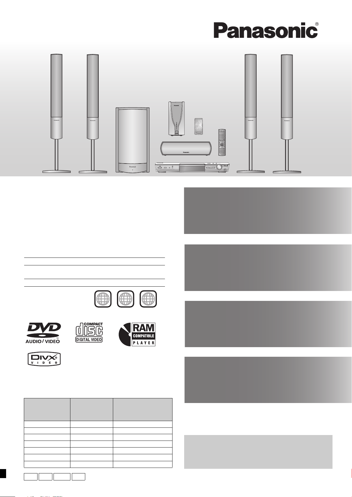
System SC-HT885W
Main unit SA-HT885W SA-HT885W
Front speakers SB-FS930 SB-FS881
Center speaker SB-PC930 SB-PC880
Surround speakers SB-FS880 SB-FS881
Active subwoofer SB-WA885 SB-WA885
Digital transmitter SH-FX50T SH-FX50T
Digital receiver SE-FX50 SE-FX50
[Continental[Europe]
[the[Middle[East,[South[Africa,]
2
2
3
5
SC-HT885W
[Southeast[Asia,]
[Saudi[Arabia[and[Kuwait]
Before connecting, operating or adjusting this product,
please read the instructions completely.
Please keep this manual for future reference.
≥Unless otherwise indicated, illustrations in these operating
instructions are for Continental Europe.
≥Operations in these instructions are described mainly with
the remote control, but you can perform the operations on the
main unit if the controls are the same.
EG GC GCS GS
RQT8221-2B
CAUTION!
(Back of product)
(Inside of product)
(Produktets innside)
(Tuotteen sisällä)
THIS PRODUCT UTILIZES A LASER.
USE OF CONTROLS OR ADJUSTMENTS OR PERFORMANCE
OF PROCEDURES OTHER THAN THOSE SPECIFIED HEREIN
MAY RESULT IN HAZARDOUS RADIATION EXPOSURE.
DO NOT OPEN COVERS AND DO NOT REPAIR YOURSELF.
REFER SERVICING TO QUALIFIED PERSONNEL.
WARNING:
TO REDUCE THE RISK OF FIRE, ELECTRIC SHOCK OR
PRODUCT DAMAGE, DO NOT EXPOSE THIS APPARATUS TO
RAIN, MOISTURE, DRIPPING OR SPLASHING AND THAT NO
OBJECTS FILLED WITH LIQUIDS, SUCH AS VASES, SHALL
BE PLACED ON THE APPARATUS.
SUOMI
VAROI TUS !
LAITTEEN KÄYTTÄMINEN MUULLA KUIN TÄSSÄ
KÄYTTÖOHJEESSA MAINITULLA TAVALLA SAATTAA
ALTISTAA KÄYTTÄJÄN TURVALLISUUSLUOKAN 1
YLITTÄVÄLLE NÄKYMÄTTÖMÄLLE LASERSÄTEILYLLE.
VAROI TUS :
TULIPALO-, SÄHKÖISKUVAARAN TAI TUOTETTA
KOHTAAVAN MUUN VAHINGON VÄHENTÄMISEKSI EI
LAITETTA SAA ALTISTAA SATEELLE, KOSTEUDELLE,
VESIPISAROILLE TAI ROISKEELLE, EIKÄ NESTETTÄ
SISÄLTÄVIÄ ESINEITÄ, KUTEN ESIMERKIKSI MALJAKOITA,
SAA ASETTAA LAITTEEN PÄÄLLE.
CAUTION!
≥DO NOT INSTALL OR PLACE THIS UNIT IN A BOOKCASE,
BUILT-IN CABINET OR IN ANOTHER CONFINED SPACE.
ENSURE THE UNIT IS WELL VENTILATED. TO PREVENT
RISK OF ELECTRIC SHOCK OR FIRE HAZARD DUE TO
OVERHEATING, ENSURE THAT CURTAINS AND ANY
OTHER MATERIALS DO NOT OBSTRUCT THE
VENTILATION VENTS.
≥DO NOT OBSTRUCT THE UNIT’S VENTILATION OPENINGS
WITH NEWSPAPERS, TABLECLOTHS, CURTAINS, AND
SIMILAR ITEMS.
≥DO NOT PLACE SOURCES OF NAKED FLAMES, SUCH AS
LIGHTED CANDLES, ON THE UNIT.
≥DISPOSE OF BATTERIES IN AN ENVIRONMENTALLY
FRIENDLY MANNER.
This product may receive radio interference caused by mobile
telephones during use. If such interference is apparent, please
increase separation between the product and the mobile telephone.
The socket outlet shall be installed near the equipment and easily
accessible or the mains plug or an appliance coupler shall remain
readily operable.
For Continental Europe
THIS UNIT IS INTENDED FOR USE IN MODERATE CLIMATES.
For Southeast Asia, the Middle East, South Africa,
Saudi Arabia and Kuwait
THIS UNIT IS INTENDED FOR USE IN TROPICAL CLIMATES.
For Southeast Asia, the Middle East, South Africa,
Saudi Arabia and Kuwait
CAUTION:
The AC voltage is different according to the area.
Be sure to set the proper voltage in your area before use.
(For details, please refer to page 8.)
For the digital receiver only
Although the AC power switch is in the “OFF” position, the unit is not
completely disconnected from the mains. Remove the plug from the
main electrical outlet if you will not be using the unit for an extended
period of time. Place the unit so the plug can be easily removed.
VAROI TUS !
≥ÄLÄ ASENNA TAI LAITA TÄTÄ LAITETTA
KABINETTITYYPPISEEN KIRJAKAAPPIIN TAI MUUHUN
SULJETTUUN TILAAN, JOTTA TUULETUS ONNISTUISI.
VARMISTA, ETTÄ VERHO TAI MIKÄÄN MUU MATERIAALI
EI HUONONNA TUULETUSTA, JOTTA VÄLTETTÄISIIN
YLIKUUMENEMISESTA JOHTUVA SÄHKÖISKU- TAI
TULIPALOVAARA.
≥ÄLÄ PEITÄ LAITTEEN TUULETUSAUKKOJA
SANOMALEHDELLÄ, PÖYTÄLIINALLA, VERHOLLA TAI
MUULLA VASTAAVALLA ESINEELLÄ.
≥ÄLÄ ASETA PALAVAA KYNTTILÄÄ TAI MUUTA AVOTULEN
LÄHDETTÄ LAITTEEN PÄÄLLE.
≥HÄVITÄ PARISTOT LUONTOA VAHINGOITTAMATTOMALLA
TAVALLA.
TÄMÄ LAITE ON TARKOITETTU KÄYTETTÄVÄKSI LEUDOSSA
ILMASTOSSA.
Laite tulee asettaa lähelle verkkopistorasiaa ja pistokkeen täytyy
olla sellaisessa asennossa, että siihen on helppo tarttua
ongelman sattuessa.
Koskee ainoastaan digitaalivastaanotinta
Vaikka virtakytkin on ”OFF”-asennossa, laite ei ole kokonaan irti
verkkovirrasta. Irrota virtajohto pistorasiasta, jos laitetta ei aiota
käyttää pitkään aikaan. Sijoita laite siten, että virtajohto on
helposti irrotettavissa.
NORSK
ADVARSEL!
DETTE PRODUKTET ANVENDER EN LASER.
BETJENING AV KONTROLLER, JUSTERINGER ELLER
ANDRE INNGREP ENN DE SOM ER BESKREVET I DENNE
BRUKSANVISNING, KAN FØRE TIL FARLIG BESTRÅLING.
DEKSLER MÅ IKKE ÅPNES, OG FORSØK ALDRI Å
REPARERE APPARATET PÅ EGENHÅND. ALT SERVICE OG
REPARASJONSARBEID MÅ UTFØRES AV KVALIFISERT
PERSONELL.
ADVARSEL:
FOR Å REDUSERE FAREN FOR BRANN, ELEKTRISK STØT
ELLER SKADER PÅ PRODUKTET, MÅ DETTE APPARATET
IKKE UTSETTES FOR REGN, FUKTIGHET, VANNDRÅPER
ELLER VANNSPRUT. DET MÅ HELLER IKKE PLASSERES
GJENSTANDER FYLT MED VANN, SLIK SOM
BLOMSTERVASER, OPPÅ APPARATET.
RQT8221
2
CLASS 1
LASER PRODUCT
LUOKAN 1 LASERLAITE
KLASS 1 LASER APPARAT
ADVARSEL!
≥APPARATET MÅ IKKE PLASSERES I EN BOKHYLLE, ET
INNEBYGGET KABINETT ELLER ET ANNET LUKKET
STED HVOR VENTILASJONSFORHOLDENE ER
UTILSTREKKELIGE. SØRG FOR AT GARDINER ELLER
LIGNENDE IKKE FORVERRER
VENTILASJONSFORHOLDENE, SÅ RISIKO FOR
ELEKTRISK SJOKK ELLER BRANN FORÅRSAKET AV
OVERHETING UNNGÅS.
≥APPARATETS VENTILASJONSÅPNINGER MÅ IKKE
DEKKES TIL MED AVISER, BORDDUKER , GARDINER OG
LIGNENDE.
≥PLASSER IKKE ÅPEN ILD, SLIK SOM LEVENDE LYS,
OPPÅ APPARATET.
≥BRUKTE BATTERIER MÅ KASSERES UTEN FARE FOR
MILJØET.
DETTE APPARATET ER BEREGNET TIL BRUK UNDER
MODERATE KLIMAFORHOLD.
Utstyret bør plasseres i nærheten av AC-stikkontakten, og
støpslet må være lett tilgjengelig hvis det skulle oppstå
problemer.
Bare for digital mottaker
Selv om av/på-bryteren er i „OFF” (av)-stilling, er ikke enheten
helt frakoblet strømnettet. Trekk ut støpselet fra stikkontakten
hvis du ikke kommer til å bruke enheten igjen på en stund.
Plasser enheten slik at det er lett å trekke ut støpselet.

Caution for AC Mains Lead
Table of contents
(For Saudi Arabia and Kuwait)
(“GS” area code models only)
For your safety, please read the following text carefully.
This appliance is supplied with a moulded three pin mains plug for
your safety and convenience.
A 5-ampere fuse is fitted in this plug.
Should the fuse need to be replaced please ensure that the
replacement fuse has a rating of 5-ampere and that it is approved by
ASTA or BSI to BS1362.
Check for the ASTA mark Ï or the BSI mark Ì on the body of the fuse.
If the plug contains a removable fuse cover you must ensure that it is
refitted when the fuse is replaced.
If you lose the fuse cover the plug must not be used until a
replacement cover is obtained.
A replacement fuse cover can be purchased from your local dealer.
CAUTION!
IF THE FITTED MOULDED PLUG IS UNSUITABLE FOR THE
SOCKET OUTLET IN YOUR HOME THEN THE FUSE SHOULD
BE REMOVED AND THE PLUG CUT OFF AND DISPOSED OF
SAFELY.
THERE IS A DANGER OF SEVERE ELECTRICAL SHOCK IF THE
CUT OFF PLUG IS INSERTED INTO ANY 13-AMPERE SOCKET.
If a new plug is to be fitted please observe the wiring code as stated
below.
If in any doubt please consult a qualified electrician.
IMPORTANT
The wires in this mains lead are coloured in accordance with the
following code:
Blue: Neutral, Brown: Live.
As these colours may not correspond with the coloured markings
identifying the terminals in your plug, proceed as follows:
The wire which is coloured Blue must be connected to the terminal
which is marked with the letter N or coloured Black or Blue.
The wire which is coloured Brown must be connected to the terminal
which is marked with the letter L or coloured Brown or Red.
WARNING: DO NOT CONNECT EITHER WIRE TO THE
EARTH TERMINAL WHICH IS MARKED WITH THE
LETTER E, BY THE EARTH SYMBOL Ó OR COLOURED
GREEN OR GREEN/YELLOW.
THIS PLUG IS NOT WATERPROOF—KEEP DRY.
Before use
Remove the connector cover.
How to replace the fuse
The location of the fuse differ according to the type of AC mains plug (figures
A and B). Confirm the AC mains plug fitted and follow the instructions below.
Illustrations may differ from actual AC mains plug.
1. Open the fuse cover with a screwdriver.
Figure A
2. Replace the fuse and close or attach the fuse cover.
Figure A
Fuse
(5 ampere)
Figure B
Fuse cover
Figure B
Fuse
(5 ampere)
Getting started
Caution for AC Mains Lead . . . . . . . . . . . . . . . . . . . . . . . 3
Accessories. . . . . . . . . . . . . . . . . . . . . . . . . . . . . . . . . . . . 3
Simple setup
STEP 1 Front and surround speaker assembly . . . . 4
STEP 2 Positioning . . . . . . . . . . . . . . . . . . . . . . . . . . . 5
STEP 3 Connecting speakers with the subwoofer
and the digital receiver . . . . . . . . . . . . . . . . 6
STEP 4 Video connections. . . . . . . . . . . . . . . . . . . . . 7
STEP 5 The digital transmitter, radio and
system connections . . . . . . . . . . . . . . . . . 8
STEP 6 The remote control . . . . . . . . . . . . . . . . . . . . 8
STEP 7 QUICK SETUP . . . . . . . . . . . . . . . . . . . . . . . . 9
STEP 8 Turning on the digital receiver . . . . . . . . . . . 9
Control reference guide . . . . . . . . . . . . . . . . . . . . . . . . . 10
Discs that can be played . . . . . . . . . . . . . . . . . . . . . . . . 11
Disc operations
Basic play . . . . . . . . . . . . . . . . . . . . . . . . . . . . . . . . . 12
Using the main unit/Using the remote control
Convenient functions . . . . . . . . . . . . . . . . . . . . . . . . . . . 14
Displaying current playback condition (QUICK OSD)/
Reviewing titles to play (ADVANCED DISC REVIEW)/
Quick replay/Skipping 30 seconds forward/
Changing the zoom ratio/Changing soundtracks/
Changing subtitles/Angle selection and Still picture rotation/
advance/Changing play speed/
Repeat play/All group, Program and Random play
Using navigation menus . . . . . . . . . . . . . . . . . . . . . . . . 16
Playing data discs/Playing from the selected track in the CD/
Playing HighMATTM discs/Playing RAM/DVD-RW (DVD-VR) discs
Using on-screen menus . . . . . . . . . . . . . . . . . . . . . . . . . 18
Main menu/Other Settings
Changing the player settings. . . . . . . . . . . . . . . . . . . . . 20
Changing the delay time (Speaker Settings)
Other operations
The radio . . . . . . . . . . . . . . . . . . . . . . . . . . . . . . . . . . . . . 22
Automatic presetting/Selecting the preset channels/
Manual tuning/RDS broadcasting/
Optional antenna connections
Sound field and sound quality. . . . . . . . . . . . . . . . . . . . 24
Sound Field Control/Super Surround/Center Focus/
Dolby Pro Logic II/Down-mixing/Enhancing the bass sound/
Subwoofer level/Speaker level adjustments
Operating other equipment . . . . . . . . . . . . . . . . . . . . . . 26
Operating the television and the video cassette recorder/
Operating the tape deck
Other useful functions . . . . . . . . . . . . . . . . . . . . . . . . . . 28
Sleep timer/Muting/Using headphones/Enjoying Karaoke
Reference
Other speaker setup options . . . . . . . . . . . . . . . . . . . . . 29
About DivX VOD content . . . . . . . . . . . . . . . . . . . . . . . . 30
Disc handling . . . . . . . . . . . . . . . . . . . . . . . . . . . . . . . . . 30
Glossary. . . . . . . . . . . . . . . . . . . . . . . . . . . . . . . . . . . . . . 30
Maintenance . . . . . . . . . . . . . . . . . . . . . . . . . . . . . . . . . . 30
Safety precautions . . . . . . . . . . . . . . . . . . . . . . . . . . . . . 31
Language code list . . . . . . . . . . . . . . . . . . . . . . . . . . . . . 31
Specifications . . . . . . . . . . . . . . . . . . . . . . . . . . . . . . . . . 32
Troubleshooting guide. . . . . . . . . . . . . . . . . . . . . . . 33–35
Caution for AC Mains Lead / Table of Contents / Accessories
Accessories
Please check and identify the
supplied accessories.
∏ 1 Remote control
(EUR7722XC0)
∏ 2 Remote control
batteries
∏ 1 AM loop antenna
∏ 1 FM indoor antenna
∏ AC mains leads
[Continental[Europe,\
[Southeast[Asia,]
[the[Middle[East,[South[Africa,[
[Saudi[Ara bia[and[Kuwa it[
[Saudi[Ara bia[and[Kuwa it]
∏ 1 Video cable
∏ 1 System cable
∏ 1 Speaker cable
∏ 1 Sheet of speaker-
cable stickers
∏ 8 Long screws
∏ 8 Short screws
∏ 4Pipes
2kpipes with short cable
k
pipes with long cable
2
∏ 4 Bases
RQT8221
3
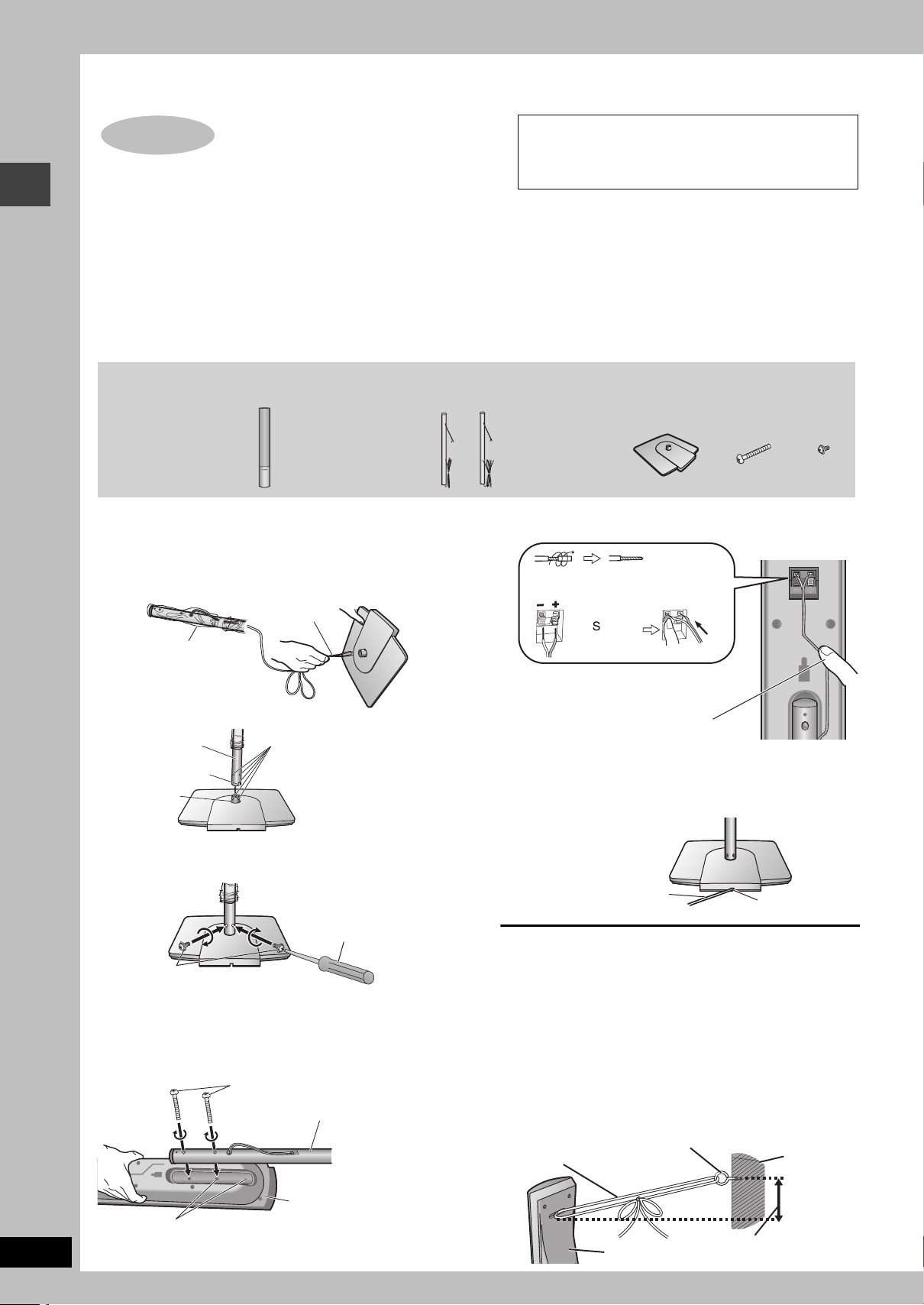
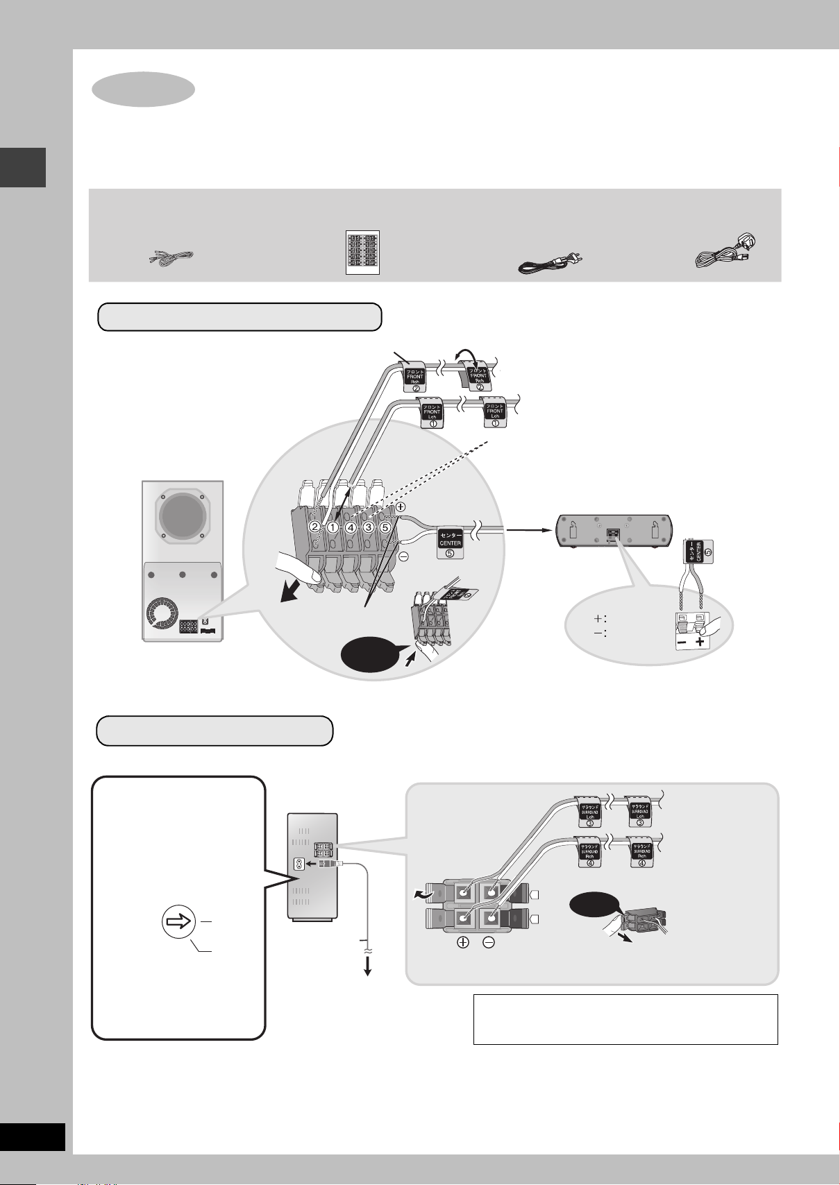
Simple setup
STEP
1
Front and surround
speaker assembly
The supplied stands are specially designed for
attachment to Panasonic SB-FS930 front speakers,
SB-FS880 surround speakers, or SB-FS881 front or
surround speakers. Use only as indicated in this setup.
[Continental[Europe\
2 Front and
2 Surround speakers
[Southeast[Asia,]
[the[Middle[East,[South[Africa,[
[Saudi[Arabia[and[Kuwait[
4 Front/Surround
speakers
4 Bases
8Long
screws
8Short
screws
Pipes
≥2kpipes with short cable: For front speakers
≥2kpipes with long cable: For surround speakers
Cable
Base
Leave the excess speaker
cable for connecting later.
Plastic wrap
Insert the pipe while gently
pulling on the speaker cable.
Match the groove and these
holes with the base when you
insert the pipe.
Pipe support
Pipe
Base
Groove
Short screws
Phillips-head
screwdriver (not included)
Before proceeding to the next step, please remove the plastic
wrap from the pipe.
Speaker
Long screws
Pipe
Twist off the vinyl ends of the
speaker cables.
§
Rear of the speaker
_: Copper
`:
Silver
Push!
If there is any excess speaker cable, thread the speaker cable
into the opening near the top of the pipe while pulling the speaker
cable from the bottom of the base.
Press the speaker cable into the
groove.
§
If the speaker cables do not have vinyl
tips, directly connect them to the
terminals.
Rear side
of base
Press the speaker cable into
the base cover groove as far
as possible.
Cable
Groove
String (not included)
Wall
Screw eye (not included)
Rear of the speaker
Approx. 150 mm
Preparation
≥To prevent damage or scratches, lay down a soft cloth and perform assembly on it.
≥For assembly, use a Phillips-head screwdriver.
≥Make sure you have all the indicated components before starting assembly, setup, and connection.
≥There is no difference between the right and left speakers and pipes.
[Note]
≥To prevent the speaker cables from being pulled out of the pipes, leave the plastic wrap on the pipes while assembling the speaker stands.
≥[Continental[Europe\
The front and surround speaker pairs as well as the pipe pairs are different.
–Check the label on the rear of the speaker before attaching the pipe (➜ page 5).
–The pipe with the shorter cable is for the front speaker.
Front and surround speaker assembly
1 Assemble the speaker stands.
1 Thread the speaker cable through the base.
For quicker threading, loosely fold the cable in half (do not
crease), pass the folded portion through the hole, and then pull
the rest of the cable through the base.
2 Insert the pipe.
3 Secure the pipe to the base.
Ensure the screws are securely fastened.
2 Attach the stands to the speakers.
Ensure the stand is fastened on straight by gradually tightening the
top and bottom screws alternately until fully tightened.
RQT8221
4
You can also attach to the lower rear of the speaker.
The height of the speaker can be changed when attaching the
stand to the upper rear or lower rear of the speaker.
3 Connect the speaker cables.
4 Secure the speaker cables to the bases.
∫ Preventing the speakers from falling over
Preparation
Attach screw eyes (not included) to secure the speakers to the wall
(➜ diagram below).
≥You will need to obtain the appropriate screw eyes to match the
walls or pillars to which they are going to be fastened.
≥Consult a qualified housing contractor concerning the
appropriate procedure when attaching to a concrete wall or a
surface that may not have strong enough support. Improper
attachment may result in damage to the wall or speakers.
1 Thread the string (not included) through the slot on the
rear of the speaker to prevent it from falling over.
2 Loop the string through the screw eye and tie tightly.
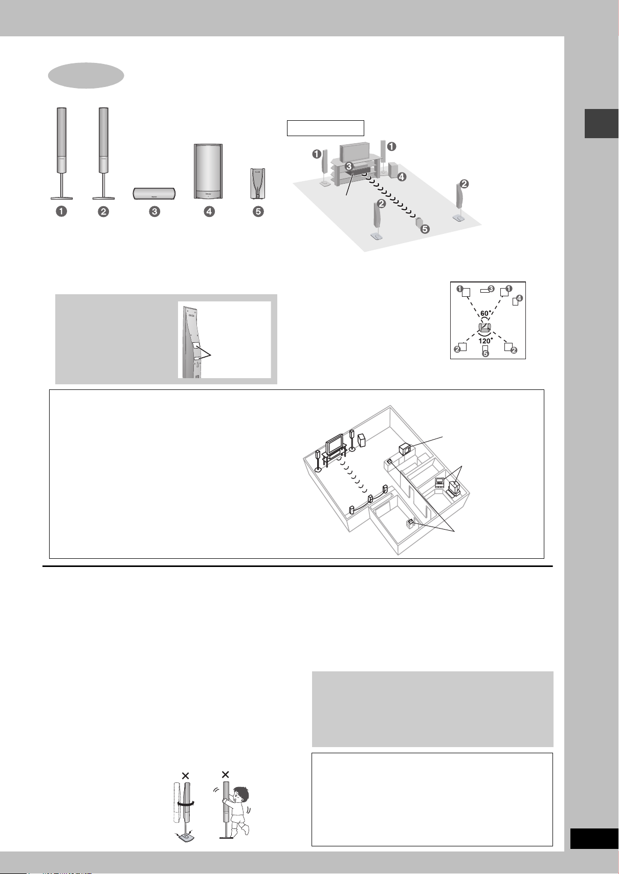
STEP
2
Positioning
The subwoofer illustration shows
the model for Continental Europe.
Setup example
FRONT
(L, R)
SURROUND
(L, R)
CENTER
ACTIVE
SUBWOOFER
[Continental[Europe\
Do not use a front
speaker as a surround
speaker or vice versa.
Verify the type of speaker
with the label on the rear
of the front speaker.
Speaker labels
DIGITAL
RECEIVER
How you set up your speakers can affect the bass and the sound field. Note the following
points:
≥Place speakers on flat secure bases.
≥Placing speakers too close to floors, walls, and corners can result in excessive bass.
Cover walls and windows with thick curtains.
Other speaker setup options
(➜ page 29)
≥
Place the digital receiver within approximately 10 m from the main unit.
≥
Do not place the main unit or receiver in a metal cabinet or bookshelf.
Main unit
Place the front, center, and
surround speakers at
approximately the same
distance from the seating
position. The angles in the
diagram are approximate.
Additional information for wireless setup
This product uses the same radio frequencies as other devices § that
may be present in your home. To help avoid any interference these
other devices may cause during the operation of this product, do not
place them near or in between the transmitter and receiver unit.
This product will automatically seek a clear channel if any of these
other devices interfere with its communication. When this happens
you may notice the blue light on the receiver unit or “ [W] ” (the
wireless indicator) in the main unit’s display flashes, and a brief
interruption in audio coming from the surround speakers. This is
the normal operation of the product working to assure the best
possible performance of your Home Theater System. If the
interference persists, try moving the other devices to another
location outside the range of this product.
§
These other devices include some cordless phones and wireless
computer LAN devices operating in the 2.4GHz band, as well as
microwave ovens.
cordless phone
personal computer
with wireless LAN
microwave oven
e.g.
[Continental[Europe\
The left and right speakers are the same with respect to the
front and surround speaker pairs.
[Southeast[Asia,[the[Middle[East,[South[Africa,[Saudi[Arabia[and[Kuwait[
The left and right front, and left and right surround speakers are all identical.
AC IN
Positioning
≥Use only supplied speakers
Using other speakers can damage the unit, and sound quality will
be negatively affected.
≥Set the speakers up on an even surface to prevent them from
falling. Take proper precautions to prevent the speakers from
falling if you cannot set them up on an even surface.
Main unit
[Note]
Keep your speakers at least 10 mm away from the system for
proper ventilation.
Center speaker
≥Vibration caused by the center speaker can disrupt the picture if it
is placed directly on the television. Put the center speaker on a
rack or shelf.
≥To prevent the speakers from falling, do not place directly on top
of the television.
Active subwoofer
Place to the right or left of the television, on the floor or a sturdy shelf
so that it won’t cause vibration. Leave about 30 cm from the television,
and 10 cm at the rear for ventilation.
Caution
Do not stand on the base and
shake the speaker.
Be cautious when children are
near.
Notes on speaker use
≥You can damage your speakers and shorten their useful life if you
play sound at high levels over extended periods.
≥Reduce the volume in the following cases to avoid damage:
– When playing distorted sound.
– When the speakers are reverberating due to a record player, a
microphone (except [Continental[Europe]), noise from FM
broadcasts, continuous signals from an oscillator, test disc, or
electronic instrument.
– When adjusting the sound quality.
– When turning the unit on or off.
If irregular coloring occurs on your television
The supplied speakers are designed to be used close to a
television, but the picture may be affected with some televisions
and setup combinations.
If this occurs, turn the television off for about 30 minutes.
The television’s demagnetizing function should correct the
problem. If it persists, move the speakers farther away from the
television.
Caution
≥The active subwoofer, supplied speakers and digital
receiver are to be used only as indicated in this setup.
Failure to do so may lead to damage to the amplifier, the
speakers and/or digital receiver, and may result in the risk
of fire. Consult a qualified service person if damage has
occurred or if you experience a sudden change in
performance.
≥Do not attempt to attach these speakers to walls using
methods other than those described in this manual.
RQT8221
5
≥Attach the speaker-cable stickers to make connection easier.
STEP
3
Connecting speakers with the subwoofer and the
digital receiver
Click!
Sheet of speaker-cable stickers
Speaker-cable sticker
2 FRONT (R)
1 FRONT (L)
5 CENTER
ACTIVE
SUBWOOFER
Insert the wire fully.
Click!
Speaker cable
(For center speaker)
Copper
Silver
AC mains lead
[Continental]Europe,]Southeast[Asia,]
[the[Middle[East,[South[Africa,]
[Saudi[Arabia[and[Kuwait]
Front and center speaker connection
Connect the surround speaker cables here only if you do
not intend to use the digital receiver (➜ below).
4 SURROUND (R), 3 SURROUND (L)
[Saudi[Arabia[and[Kuwait]
The illustration shows the model for Continental Europe.
VOLT
ADJ
110127V
220240V
Click!
i: Copper
j: Silver
≥Connect the AC mains lead after speaker cable connections are complete.
To household
mains socket
AC mains lead
DIGITAL
RECEIVER
4 SURROUND (R)
3 SURROUND (L)
Surround speaker connection
The illustration shows the model for Continental Europe.
[Southeast[Asia,[the[Middle[East,]
[South[Africa,[Saudi[Arabia]
[and[Kuwait]
Before connecting the
AC mains lead
Set the voltage.
Use a flat-head screwdriver to
turn the voltage selector on the
back of the receiver to the
appropriate position for the area
in which this system is used.
[Saudi[Arabia]and[Kuwait]
BE SURE TO READ THE CAUTION FOR THE AC
MAINS LEAD ON PAGE 3 BEFORE CONNECTION.
≥The terminals of the subwoofer and the digital receiver have high output power. Carefully connect the speaker wires.
Connecting speakers with the subwoofer and the digital receiver
VOLTVOLT
ADJADJ
220-220-
240V240V
110-110-
127V127V
AC IN~
.
4
RQT8221
6
[Note]
≥Never short-circuit positive (i) and negative (j) speaker wires.
≥Be sure to connect only positive (copper) wires to positive (i) terminals and negative (silver) wires to negative (j) terminals. Incorrect
connection can damage the speakers.
≥Do not use more than one pair of surround speakers when using this wireless system.
≥Do not connect through the video cassette recorder.
STEP
4
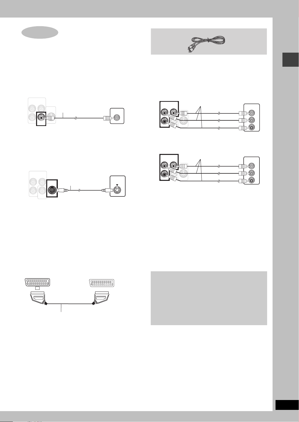
Video connections
COMPONENT VIDEO OUT
S-V IDEO
OUT
VID EO
OUT
(PROGRES SIVE/INTERL ACE)
Back of the
main unit
Video cable
(included)
Television
(not included)
S-V IDEO
OUT
Television
(not included)
S-video cable
(not included)
Back of the
main unit
Television
(not included)
Scart cable
(not included)
Back of the
main unit
Video cable
(PROGRES SIVE/INTERL ACE)
(NTSC: 4 80p/480i, P AL: 576p/57 6i)
Television
(not included)
Video cables
(not included)
Back of the
main unit
[Continental[Europe]
Television
(not included)
Video cables
(not included)
Back of the
main unit
[Southeast[Asia,[the[Middle[East,[South[Africa,[Saudi[Arabia[and[Kuwait[
Due to copy guard protection, the picture may not be displayed
properly.
≥Turn the television off before connecting, and refer to the
television’s operating instructions.
∫ Television with a VIDEO IN terminal
COMPONENT VIDEO OUT
(PROGRESSIVE/INTERLACE)
P
B
Y
S-VIDEO
OUT
P
R
VIDEO
OUT
VIDEO IN
∫ Television with an S-VIDEO IN terminal
COMPONENT VIDEO OUT
(PROGRESSIVE/INTERLACE)
P
B
Y
S-VIDEO
OUT
S-VIDEO
IN
∫
Television with COMPONENT VIDEO IN terminals
COMPONENT VIDEO OUT
(PROGRESSIVE/INTERLACE)
P
B
Y
S-VIDEO
OUT
P
R
VIDEO
OUT
COMPONENT VIDEO OUT
(NTSC: 480p/480i, PAL: 576p/576i)
P
B
Y
S-VIDEO
OUT
P
R
VIDEO
OUT
COMPONENT
VIDEO IN
COMPONENT
VIDEO IN
Y
PB
PR
Y
PB
PR
Video connections
P
R
VIDEO
OUT
S-VIDEO OUT terminal
The S-VIDEO OUT terminal achieves a more vivid picture than the
VIDEO OUT terminal by separating the chrominance (C) and
luminance (Y) signals. (Actual results depend on the television.)
[Continental[Europe]
∫ Television with SCART terminal
AV
AV
SCART (AV) terminal
To improve picture quality, you can change the video signal output
from the SCART (AV) terminal from “Video” to either “S-Video” or
“RGB” to suit the type of television you are using. Select “S-Video/
YPbPr” or “RGB/No Output” from QUICK SETUP (➜ page 9).
COMPONENT VIDEO OUT terminals
These terminals can be used for either interlace or progressive
output and provide a purer picture than the S-VIDEO OUT
terminal. Connection using these terminals outputs the color
difference signals (P
B/PR) and luminance signal (Y) separately in
order to achieve high fidelity in reproducing colors.
≥The description of the component video input terminals depends
on the television or monitor (e.g. Y/P
B/PR, Y/B-Y/R-Y, Y/CB/CR).
Connect to terminals of the same color.
[Continental[Europe]
≥When making this connection, select “Video/YPbPr” or “S-Video/
YPbPr” from QUICK SETUP (➜ page 9). If “RGB/No Output” is
selected, the RGB signal is output from the SCART (AV) terminal,
but no signal is output from the component video output
terminals.
To enjoy progressive video
≥Connect to the component video input terminals on a 625p
(or 576p) or 525p
(or 480p) compatible television. (Video will
not be displayed correctly if connected to an incompatible
television.)
[Continental[Europe]
≥Panasonic televisions with 625 (576)/50i·50p, 525 (480)/
60i·60p input terminals are progressive compatible. Consult
the manufacturer if you have another brand of television.
RQT8221
7
STEP
5
The digital transmitter, radio and system connections
TV
AUDIO
IN
VCR
VCR
AUDIOAUDIO
ININ
FM ANTFM ANT
AM ANTAM ANT
(75(75≠
)
LOOPLOO P
EXTEXT
COMPONENT VIDEO OUTCOMPONENT VIDEO OUT
(PROGRESSIV(PROGRESSIVE/INE/INTERLACE)TERLACE)
P
B
Y
P
R
L
R
S-VIDEOS-VIDEO
OUTO UT
VIDEOVIDEO
OUTOUT
A
AUXAUX
DIGITAL
TRANSMITTER
1
2
VOLT ADJ
127 V 110 V 220 V-230 V 240 V
Active subwoofer
Adhesive tape
System cable
Catch up
To disconnect
Press the catch
and pull out.
To disconnect
Press the catch
and pull out.
AC mains
lead
Main unit
≥Connect the AC mains lead after all other connections are complete.
≥Optional antenna connections (➜ page 23).
The illustration shows the model for Continental Europe.
AM loop antenna
Stand the antenna up on its base.
Place the antenna where reception is best.
Keep loose antenna cable away from other
wires and cables.
Catch up
Click!
System cable
AM loop
antenna
FM indoor
antenna
FM indoor antenna
Affix this end of the antenna
where reception is best.
To household
mains socket
Conserving power
The main unit consumes a small amount of power, even when it is turned off
(For Continental Europe: approx. 0.7 W or for Southeast Asia, the Middle East,
South Africa, Saudi Arabia and Kuwait: approx. 0.9 W). To save power when the
unit is not to be used for a long time, unplug it from the household mains socket.
You will need to reset some memory items after plugging in the unit.
[Note]
The included AC mains lead is for use with this unit only. Do not use it with other equipment.
Digital
transmitter
Digital transmitter
Insert fully until you
hear a click.
Do not insert or remove
while the main unit is on.
AC mains lead
[Continental]Europe,]Southeast[Asia,[the[Middle[East,]
[South[Africa,[Saudi[Arabia[and[Kuwait]
[Saudi[Arabia[
[and[Kuwait]
[Southeast[Asia,[the[Middle[East,[
[South[Africa,[Saudi[Arabia[and[Kuwait]
Before connecting the AC mains lead
Set the voltage.
Use a flat-head screwdriver to turn the voltage selector
on the back of the subwoofer to the appropriate position
for the area in which this system is used.
If the power supply in your area is 115 V or 120 V,
please set the voltage selector as follows:
≥For 115 V: Set to 110 V.
≥For 120 V: Set to 127 V.
[Saudi[Arabia]and[Kuwait]
BE SURE TO READ THE CAUTION FOR
THE AC MAINS LEAD ON PAGE 3 BEFORE
CONNECTION.
STEP
6
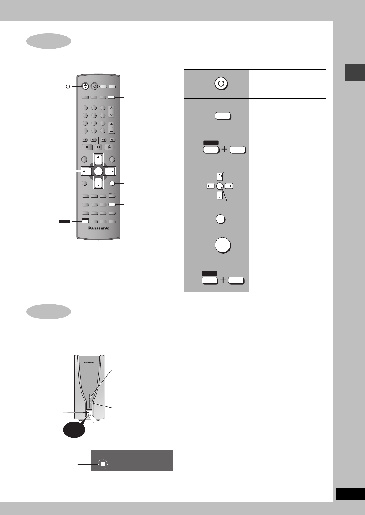
The remote control
R6/LR6, AA, UM-3
1
3
2
≥Do not use
rechargeable type
batteries.
Remote control Batteries
Insert so the poles (i and j) match those in the
remote control.
The digital transmitter, radio and system connections/The remote control
RQT8221
8
Do not:
≥mix old and new batteries.
≥use different types at the same time.
≥heat or expose to flame.
≥take apart or short circuit.
≥attempt to recharge alkaline or manganese batteries.
≥use batteries if the covering has been peeled off.
Mishandling of batteries can cause electrolyte leakage which can
damage items the fluid contacts and may cause a fire.
Remove if the remote control is not going to be used for a long
period of time. Store in a cool, dark place.
∫ Use
Aim at the remote control signal sensor (➜ page 10), avoiding
obstacles, at a maximum range of 7 m directly in front of the unit.
The QUICK SETUP screen assists you to make necessary settings.
STEP
7
QUICK SETUP
Register
Select
STEP
8
Turning on the digital receiver
Press!
Power indicator
This indicator lights
when the unit is
turned on.
Wireless link indicator
This indicator lights
when the signal strength
is adequate for proper
operation.
Power on/off
button
“ [W] ” lights up in the
display on the main unit.
(“ [W] ” is flashing ➜ page 35, Unit displays)
Turn on the television and select the appropriate video input on the television.
3, 4, 2, 1
ENTER
SHIFT
AV SYSTEM
AUX
TV/AV
12
45
7
CANCEL
SKIP
TOP MENU
DIRECT
NAVIGATOR
FUNCTIONS
SUBWOOFER
SUPER SRND
LEVEL
H.BASS
SLEEP
MANUAL SKIP
QUICK OSD
ANGLE/PAGE
FL DISPLAY REPEAT
GROUP
ADVANCED
SHIFT
DISC REVIEW
8
0
ENTER
ZOOM
TV
DVD/CD
TUNER/BAND
3
6
VOLUME
9
-/--
S10
SLOW/SEARCH
C.FOCUS
SFC
SUBTITLE
AUDIO
PLAY SPEED
QUICK REPLAY
VCR
CH
MENU
PLAY
LIST
RETURN
TV VOLTV VOL
MIX 2CH
PL
SETUP
MUTING
PLAY MODE
TEST
CH SELECT
DVD/CD
RETURN
SETUP
To change these settings later
Select “QUICK SETUP” in the “Others” tab (➜ page 21).
1
2
3
4
5
DVD/CD
SHIFT
RETURN
ENTER
ENTER
SETUP
MUTING
Turn on the main unit.
Select “DVD/CD”.
Show the QUICK
SETUP screen.
Follow the messages
and make the settings.
QUICK SETUP/Turning on the digital receiver
Press to finish QUICK
SETUP.
1 Turn on the main unit. (➜ above)
2 Turn on the digital receiver.
6
SHIFT
SETUP
MUTING
Press to exit.
[Note]
To save power when your home theater system is not being used,
first turn off the digital receiver followed by the main unit.
W
RQT8221
9
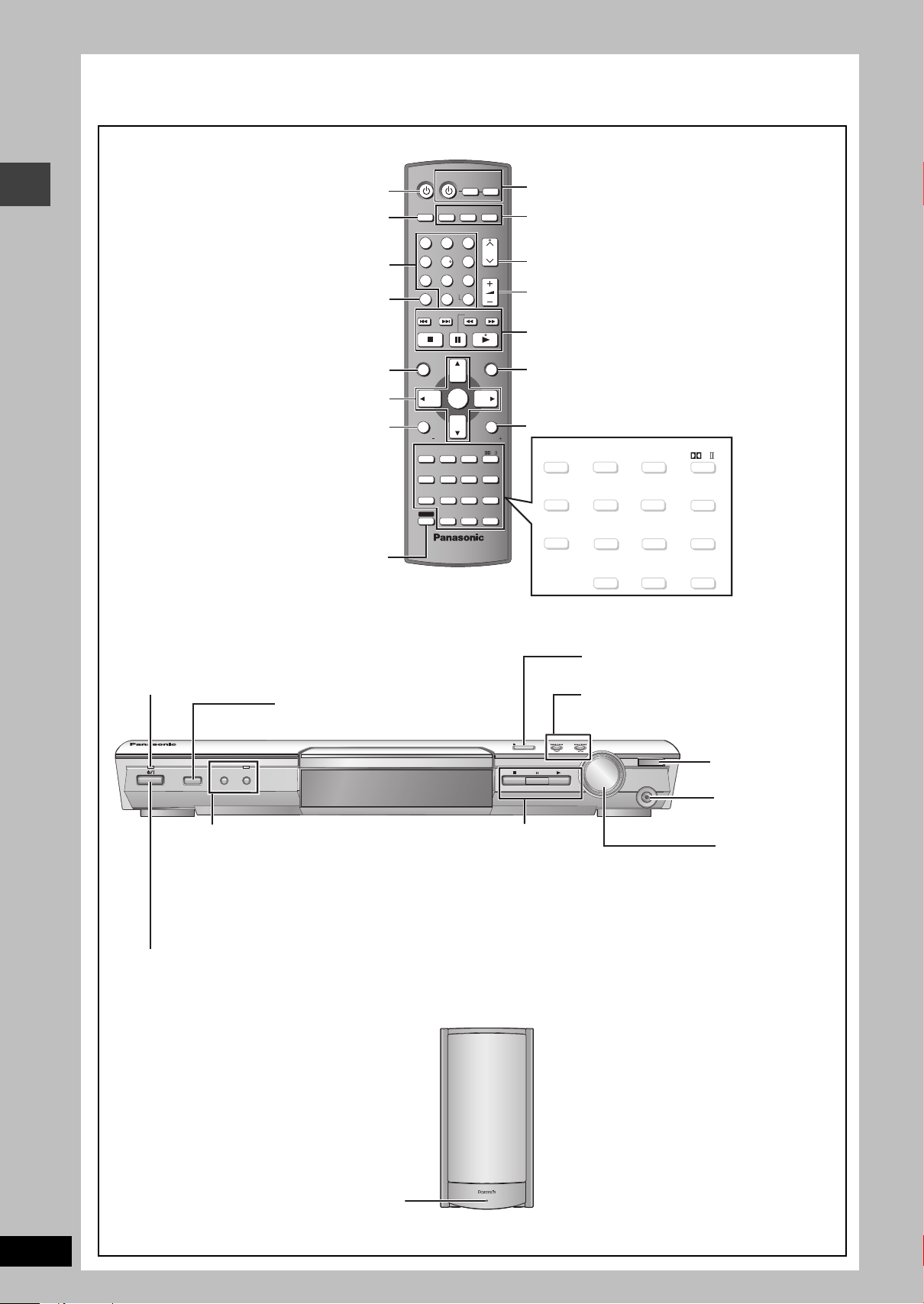
Control reference guide
VOLUME
CH
SKIP
SLOW/SEARCH
MENU
DIRECT
NAVIGATOR
TOP MENU
RETURN
FUNCTIONS
VCR
AUX
TV
TUNER/BAND
SUBWOOFER
LEVEL
SUPER SRND
H.BASS
C.FOCUS
SFC
PLAY MODE
TEST
CH SELECT
SETUP
MUTING
MIX 2CH
PL
ZOOM
MANUAL SKIP
SUBTITLE
AUDIO
PLAY SPEED
QUICK REPLAY
ADVANCED
DISC REVIEW
FL DISPLAY REPEAT
SHIFT
ANGLE/PAGE
GROUP
AV SYSTEM
DVD/CD
PLAY
LIST
TV VOLTV VOL
ENTER
12
6
9
45
7
8
CANCEL
0
S10
3
-/--
SLEEP
QUICK OSD
TV/AV
(25)
(24, 25)
(24) (24)
(14)
(14, 15) (20, 28)
(13) (
13, 15
)
(14, 15)
(
15
)
(15)
(14) (25)
SUBWOOFER
LEVEL
SUPER SRND
H.BASS
C.FOCUS
SFC
PLAY MODE
TEST
CH SELECT
SETUP
MUTING
MIX 2CH
PL
ZOOM
MANUAL SKIP
SUBTITLE
AUDI O
PLAY SPEED
QUICK REPLAY
SLEEP
QUICK OSD
ADVANCED
DISC REVIEW
FL DISPLAY REPEAT
ANGLE/PAGE
GROUP
(
14, 28
)
AC supply indicator [AC IN]
This indicator lights when the unit is connected to the
AC mains supply.
Standby/on indicator
When the unit is connected to the AC mains supply, this
indicator lights up in standby mode and goes out when
the unit is turned on.
INPUT SELECTOR (22)
DVD /CD#FM#AM#TV#VCR#
AUX#Return to DVD/CD
Remote control
signal sensor
<OPEN/CLOSE
Open/Close the disc tray (12)
PHONES
Connect
headphones (28)
VOLUME
Turn up/down
the volume (12)
PROGRESSIVE
Enjoy progressive video (12)
RDS ([Continental[Europe] only)
Display RDS text data (23)
H.BASS
Turn the bass sound enhancement
on/off (25)
H.BASS indicator
4, 5/X TUNING W
Skipping or slow-search play (12)/
Select the radio stations (22)
Standby/on switch [Í/I]
Press to switch the unit from on to standby mode or vice versa.
In standby mode, the unit is still consuming a small amount of power. (12)
∫/TUNE MODE
Stop playing (12)/
Select the tuning mode (22)
;/FM MODE
Pause (12)/Adjust the FM
reception condition (22)
1/MEMORY
Play discs (12)/Memorize the
receiving radio stations (22)
Select television channels and disc’s
title numbers etc./Enter numbers (13)
To use functions labeled in orange:
While pressing [SHIFT],
press the corresponding button.
Basic operations for play (12, 13)
Show a disc top menu (16) or
program list (17)
Select or register menu items on the
television screen, Frame-by-frame (13)
Show on-screen menu (18),
Display RDS text data ([Continental[Europe] only) (23)
or television volume down (27)
Channel select (22, 27)
Show a disc menu (16) or play list (17)
Return to previous screen (13) or
television volume up (27)
Switch the television’s video
input mode (27)
Adjust the volume (13)
Cancel (13)
Turn the unit on/off (9)
Television and Video cassette
recorder operations (27)
Select the source
AUX (27),TUNER/BAND (22),
DVD /CD (9)
The illustration shows the model for Continental Europe.
See reference pages in brackets.
Control reference guide
INPUT SELECTOR PROGRESSIVE
H.BASS
RDS
TUNE MODE FM MODE MEMORY
OPENCLOSE
TUNING
VOLUME
PHONES
DOWN
UP
RQT8221
10
AC IN
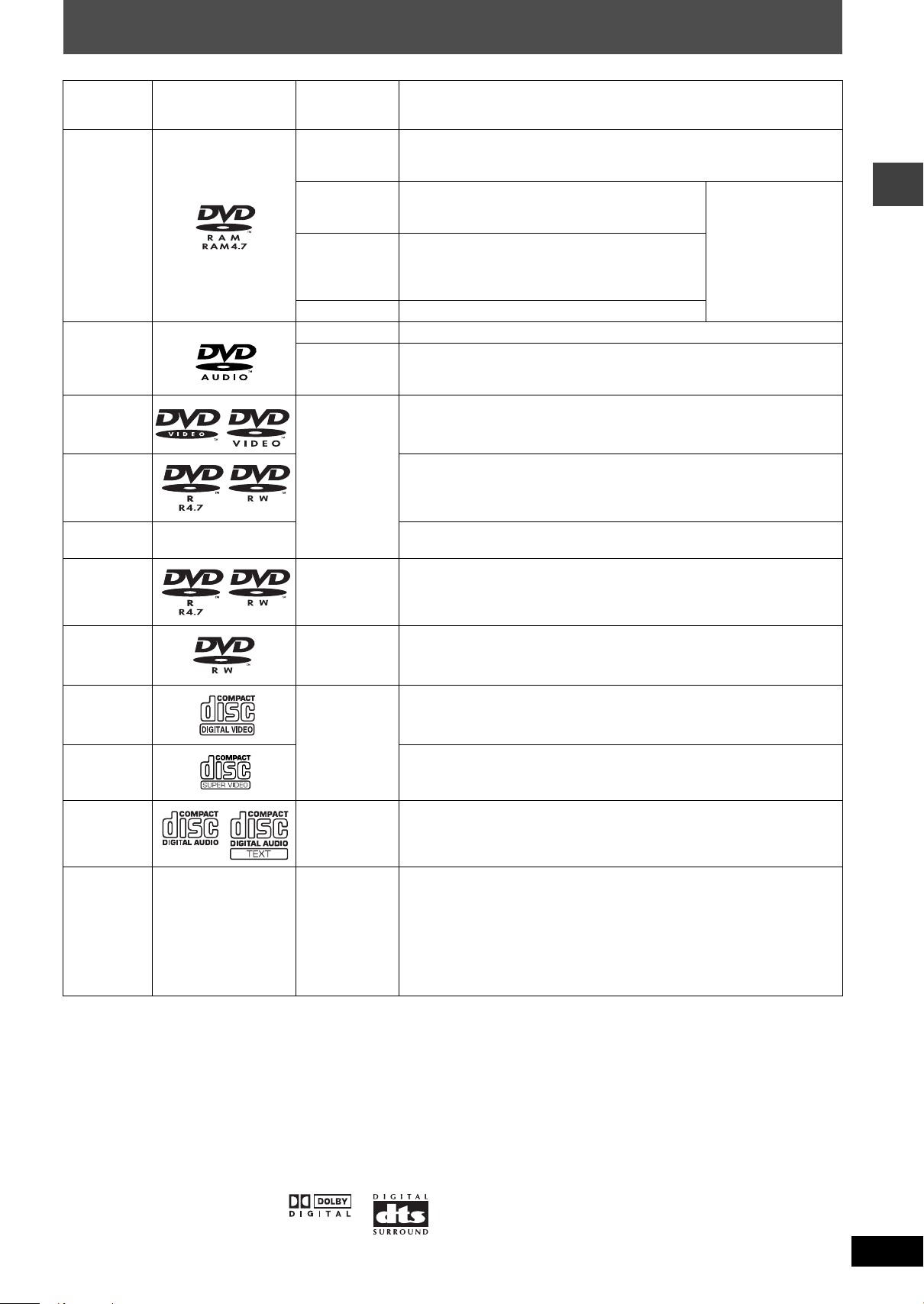
Discs that can be played
Indication in
Disc Logo
DVD-RAM
DVD-Audio
DVD-Video
these operating
instructions
[RAM]
[JPEG]
[MPEG4]
§1
[DivX]
[DVD-A] —
[DVD-V]
Remarks
Recorded with devices using Version 1.1 of the Video Recording Format (a
unified video recording standard), such as DVD video recorders, DVD video
cameras, personal computers, etc.
Recorded
video recorders
File system) Standard Version 1.0.
Recorded with Panasonic SD multi cameras or DVD
video recorders [conforming to SD VIDEO
specifications (ASF standard)/MPEG4 (Simple Profile)
video system/G.726 audio system].
—
Some DVD-Audio discs contain DVD-Video content.
To play DVD-Video content, select “Play as DVD-Video” in Other Menu
(➜ page 19).
—
with Panasonic SD multi cameras or DVD
using the DCF (Design rule for Camera
≥To play JPEG,
MPEG4 or DivX video
contents, select “Play
as Data Disc” in Other
Menu (➜ page 19).
Discs that can be played
DVD-R
(DVD-Video)/
[DVD-V]
Discs recorded and finalized
§2
on DVD video recorders or DVD video cameras.
DVD-RW
(DVD-Video)
iR (Video)/
iRW (Video)
DVD-R
(DivX Video)/
DVD-RW
—
§1
[DivX]
Discs recorded and finalized§2 on DVD video recorders or DVD video cameras.
§2
Finalize
the disc after recording.
(DivX Video)
DVD-RW
(DVD-VR)
[DVD-RW[‹VR›]
Discs recorded and finalized
using Version 1.1 of the Video Recording Format (a unified video recording
standard).
§2
on DVD video recorders or DVD video cameras
—
Video CD
[VCD]
Conforming to IEC62107
SVCD
This unit is compatible with HDCD, but does not support the Peak Extend
CD [CD]
function (a function which expands the dynamic range of high level signals).
HDCD-encoded CD’s sound better because they are encoded with 20 bits, as
compared with 16 bits for all other CD’s.
[WMA]
[MP3]
CD-R
CD-RW
—
[JPEG]
[CD]
[MPEG4]
[DivX]
§1
[VCD]
§1
Created using DivX ver.3.11, 4.x, 5.x [DivX video system/MP3, Dolby Digital or MPEG audio system].
§2
A process that allows play on compatible equipment.
≥This unit can play CD-R/RW (audio recording disc) recorded with the formats
on the left. Close the sessions or finalize
§2
the disc after recording.
≥HighMAT discs
WMA, MP3 or JPEG files only.
To play without using the HighMAT function, select “Play as Data Disc” in Other
Menu (➜ page 19).
≥[WMA] This unit does not support Multiple Bit Rate (MBR: a file that contains the
same content encoded at several different bit rates).
≥It may not be possible to play the above discs in all cases due to the type of discs, the condition of the recording, the recording method and how
the files were created (➜ page 17, Tips for making data discs).
∫ Discs that cannot be played
Version 1.0 of DVD-RW, DVD-ROM, CD-ROM, CDV, CD-G, SACD
and Photo CD, DVD-RAM that cannot be removed from their
cartridge, 2.6-GB and 5.2-GB DVD-RAM and “Chaoji VCD” available
on the market including CVD, DVCD and SVCD that do not conform
to IEC62107.
∫ Audio format of DVD’s
This unit automatically recognizes
and decodes discs with these
symbols.
∫ Video systems
– This unit can play PAL and NTSC, but your television must match
the system used on the disc.
– PAL discs cannot be correctly viewed on an NTSC television.
– This unit can convert NTSC signals to PAL 60 for viewing on a PAL
television (➜ page 21, “NTSC Disc Output” in “Video” tab).
RQT8221
11
 Loading...