

Panasonic SC-HT880W User Manual
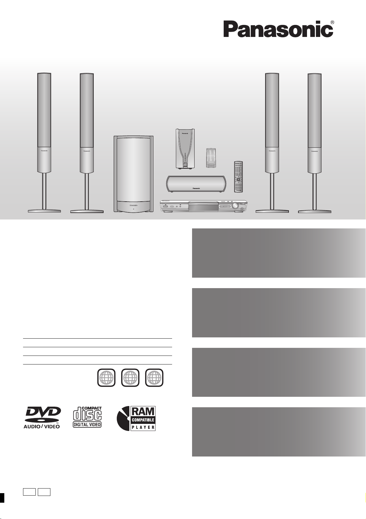
The illustration shows the model for Australia and N.Z.
AC IN
Operating Instructions
DVD Home Theater Sound System
Model No. SC-HT880W
Advanced
progressive scan
Provides a smoother and sharper image.
page
7
Region number
The player plays DVD-Video marked with labels containing the region
number or “ALL”.
Region Number
The United Kingdom 2
Australia and N.Z. 4
Example: ]Australia[and\N.Z.\
4 ALL
Before connecting, operating or adjusting this product,
please read the instructions completely.
Please keep this manual for future reference.
2
4
5
Digital Transmitter
page
and Receiver
Set your surround sound free.
9
Compatible with a variety
11
of media formats
DVD-RAM, DVD-Audio, DVD-Video and more.
page
High performance
page
sound effects
Sound field control (SFC), Bass sound enhancement and more.
[Note[
“EB” on the packaging indicates the United Kingdom.
24
GN
EB
RQT7991-2B
Dear customer
Thank you for purchasing this product. For optimum performance
and safety, please read these instructions carefully.
≥These operating instructions are applicable to models for
a variety of regions.
≥Unless otherwise indicated, illustrations in these
operating instructions are of the model for Australia and
N.Z.
≥Operations in these instructions are described mainly
with the remote control, but you can perform the
operations on the main unit if the controls are the same.
System SC-HT880W
Main unit SA-HT880W
Front speakers SB-FS930
Center speaker SB-PC930
Surround speakers SB-FS880
Active subwoofer SB-WA880
Digital transmitter SH-FX50T
Digital receiver SE-FX50
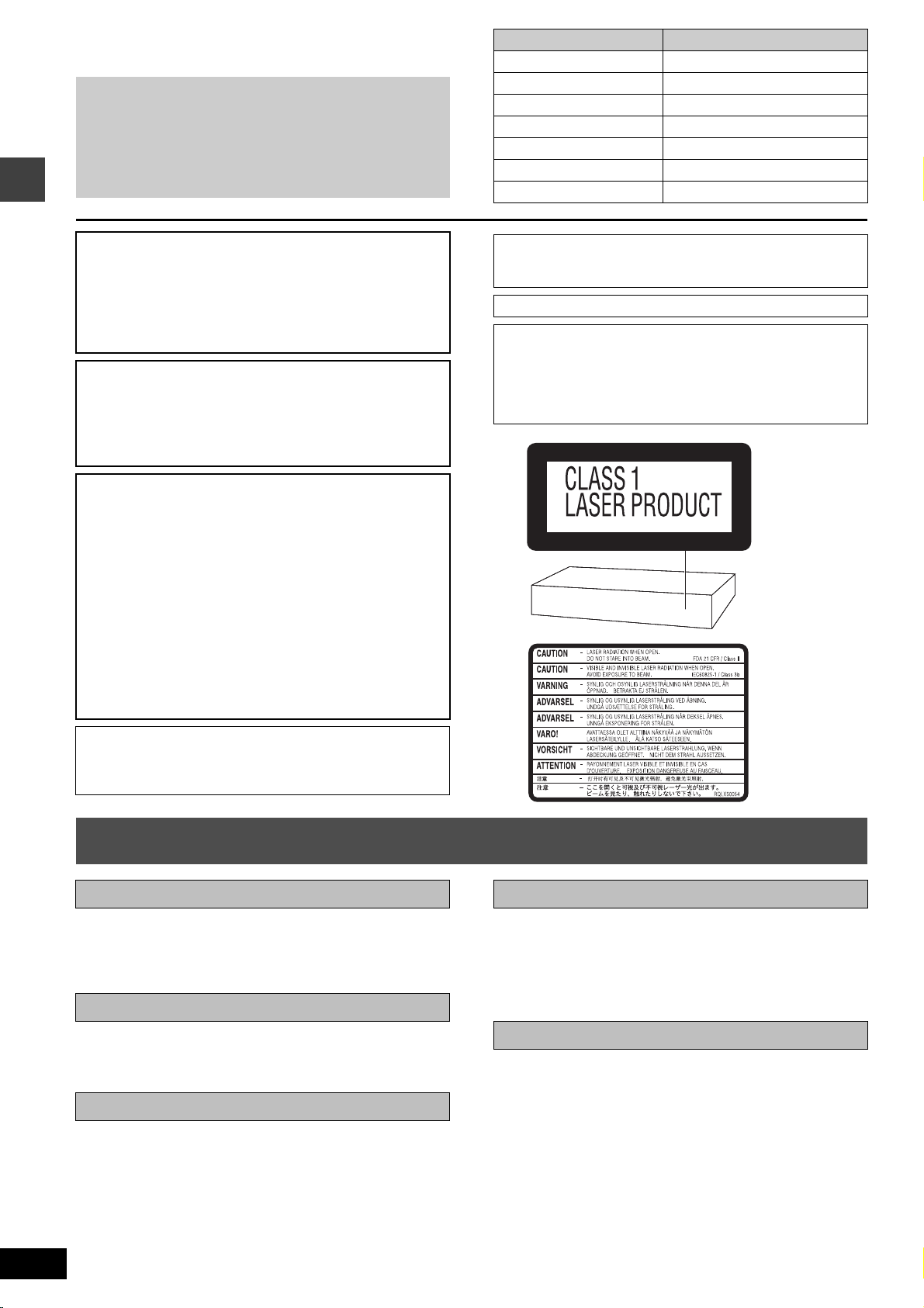
Safety precautions
CAUTION!
THIS PRODUCT UTILIZES A LASER.
USE OF CONTROLS OR ADJUSTMENTS OR PERFORMANCE
OF PROCEDURES OTHER THAN THOSE SPECIFIED HEREIN
MAY RESULT IN HAZARDOUS RADIATION EXPOSURE.
DO NOT OPEN COVERS AND DO NOT REPAIR YOURSELF.
REFER SERVICING TO QUALIFIED PERSONNEL.
WARNING:
TO REDUCE THE RISK OF FIRE, ELECTRIC SHOCK OR
PRODUCT DAMAGE, DO NOT EXPOSE THIS APPARATUS
TO RAIN, MOISTURE, DRIPPING OR SPLASHING AND THAT
NO OBJECTS FILLED WITH LIQUIDS, SUCH AS VASES,
SHALL BE PLACED ON THE APPARATUS.
CAUTION!
≥DO NOT INSTALL OR PLACE THIS UNIT IN A BOOKCASE,
BUILT-IN CABINET OR IN ANOTHER CONFINED SPACE.
ENSURE THE UNIT IS WELL VENTILATED. TO PREVENT
RISK OF ELECTRIC SHOCK OR FIRE HAZARD DUE TO
OVERHEATING, ENSURE THAT CURTAINS AND ANY
OTHER MATERIALS DO NOT OBSTRUCT THE
VENTILATION VENTS.
≥DO NOT OBSTRUCT THE UNIT’S VENTILATION OPENINGS
WITH NEWSPAPERS, TABLECLOTHS, CURTAINS, AND
SIMILAR ITEMS.
≥DO NOT PLACE SOURCES OF NAKED FLAMES, SUCH AS
LIGHTED CANDLES, ON THE UNIT.
≥DISPOSE OF BATTERIES IN AN ENVIRONMENTALLY
FRIENDLY MANNER.
The socket outlet shall be installed near the equipment and
easily accessible or the mains plug or an appliance coupler shall
remain readily operable.
THIS UNIT IS INTENDED FOR USE IN MODERATE CLIMATES.
For the digital receiver only
Although the AC power switch is in the “OFF” position, the unit is
not completely disconnected from the mains. Remove the plug
from the main electrical outlet if you will not be using the unit for
an extended period of time. Place the unit so the plug can be
easily removed.
(Back of product)
RQT7991
2
This product may receive radio interference caused by mobile
telephones during use. If such interference is apparent, please
increase separation between the product and the mobile
telephone.
Safety precautions
Placement
Set the unit up on an even surface away from direct sunlight, high
temperatures, high humidity, and excessive vibration. These
conditions can damage the cabinet and other components, thereby
shortening the unit’s service life.
Do not place heavy items on the unit.
Volt age
Do not use high voltage power sources. This can overload the unit
and cause a fire.
Do not use a DC power source. Check the source carefully when
setting the unit up on a ship or other places where DC is used.
AC mains lead protection
Ensure the AC mains lead is connected correctly and not
damaged. Poor connection and lead damage can cause fire or
electric shock. Do not pull, bend, or place heavy items on the lead.
Grasp the plug firmly when unplugging the lead. Pulling the AC
mains lead can cause electric shock.
Do not handle the plug with wet hands. This can cause electric
shock.
(Inside of product)
Foreign matter
Do not let metal objects fall inside the unit. This can cause electric
shock or malfunction.
Do not let liquids get into the unit. This can cause electric shock or
malfunction. If this occurs, immediately disconnect the unit from the
power supply and contact your dealer.
Do not spray insecticides onto or into the unit. They contain
flammable gases which can ignite if sprayed into the unit.
Service
Do not attempt to repair this unit by yourself. If sound is
interrupted, indicators fail to light, smoke appears, or any other
problem that is not covered in these instructions occurs, disconnect
the AC mains lead and contact your dealer or an authorized service
center. Electric shock or damage to the unit can occur if the unit is
repaired, disassembled or reconstructed by unqualified persons.
Extend operating life by disconnecting the unit from the power
source if it is not to be used for a long time.
Caution for AC Mains Lead
(For United Kingdom)
(“EB” area code model only)
For your safety, please read the following text carefully.
This appliance is supplied with a moulded three pin mains plug for
your safety and convenience.
A 5-ampere fuse is fitted in this plug.
Should the fuse need to be replaced please ensure that the
replacement fuse has a rating of 5-ampere and that it is approved by
ASTA or BSI to BS1362.
Check for the ASTA mark Ï or the BSI mark Ì on the body of the
fuse.
If the plug contains a removable fuse cover you must ensure that it is
refitted when the fuse is replaced.
If you lose the fuse cover the plug must not be used until a
replacement cover is obtained.
A replacement fuse cover can be purchased from your local dealer.
CAUTION!
IF THE FITTED MOULDED PLUG IS UNSUITABLE FOR THE
SOCKET OUTLET IN YOUR HOME THEN THE FUSE SHOULD
BE REMOVED AND THE PLUG CUT OFF AND DISPOSED OF
SAFELY.
THERE IS A DANGER OF SEVERE ELECTRICAL SHOCK IF
THE CUT OFF PLUG IS INSERTED INTO ANY 13-AMPERE
SOCKET.
If a new plug is to be fitted please observe the wiring code as stated
below.
If in any doubt please consult a qualified electrician.
IMPORTANT
The wires in this mains lead are coloured in accordance with the
following code:
Blue: Neutral, Brown: Live.
As these colours may not correspond with the coloured markings
identifying the terminals in your plug, proceed as follows:
The wire which is coloured Blue must be connected to the terminal
which is marked with the letter N or coloured Black or Blue.
The wire which is coloured Brown must be connected to the terminal
which is marked with the letter L or coloured Brown or Red.
WARNING: DO NOT CONNECT EITHER WIRE TO THE
EARTH TERMINAL WHICH IS MARKED WITH THE
LETTER E, BY THE EARTH SYMBOL Ó OR COLOURED
GREEN OR GREEN/YELLOW.
THIS PLUG IS NOT WATERPROOF—KEEP DRY.
Before use
Remove the connector cover.
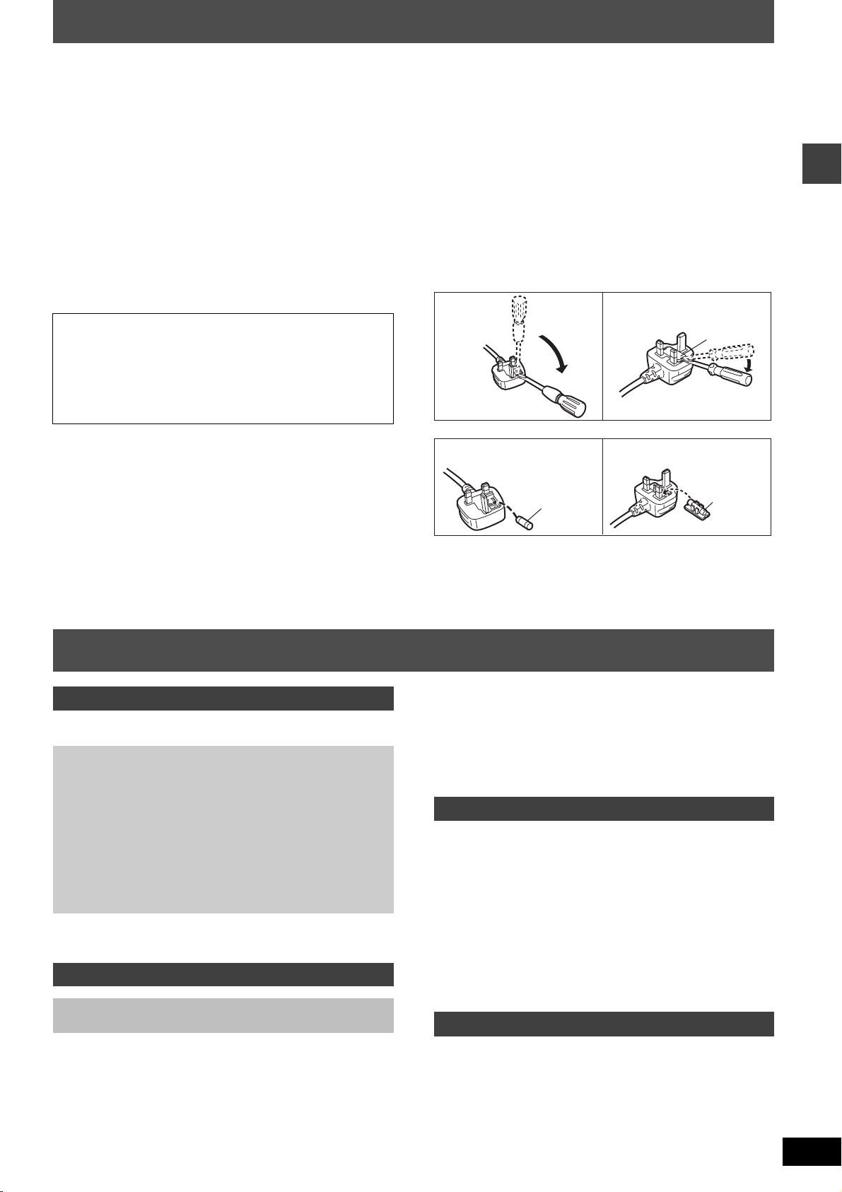
How to replace the fuse
The location of the fuse differ according to the type of AC mains plug
(figures A and B). Confirm the AC mains plug fitted and follow the
instructions below.
Illustrations may differ from actual AC mains plug.
1. Open the fuse cover with a screwdriver.
Figure A
Figure B
Fuse cover
2. Replace the fuse and close or attach the fuse cover.
Figure A
Fuse
(5 ampere)
Figure B
Fuse
(5 ampere)
Caution for AC Mains Lead/Table of contents
Table of contents
Getting started
Safety precautions . . . . . . . . . . . . . . . . . . . . . . . . . . . . . . .2
Caution for AC Mains Lead . . . . . . . . . . . . . . . . . . . . . . . .3
Simple setup
STEP 1 Front and surround speaker assembly . . . . 4
STEP 2 Positioning . . . . . . . . . . . . . . . . . . . . . . . . . . . 5
STEP 3 Connecting speakers with the subwoofer
and the digital receiver. . . . . . . . . . . . . . . . 6
STEP 4 Video connections. . . . . . . . . . . . . . . . . . . . . 7
STEP 5 The digital transmitter, radio and system
connections . . . . . . . . . . . . . . . . . . . . . . . . . 8
STEP 6 The remote control . . . . . . . . . . . . . . . . . . . . 8
STEP 7 QUICK SETUP . . . . . . . . . . . . . . . . . . . . . . . . 9
STEP 8 Turning on the digital receiver . . . . . . . . . . . 9
Control reference guide . . . . . . . . . . . . . . . . . . . . . . . . . .10
Discs that can be played . . . . . . . . . . . . . . . . . . . . . . . . .11
Disc handling . . . . . . . . . . . . . . . . . . . . . . . . . . . . . . . . . .11
Disc operations
Basic play . . . . . . . . . . . . . . . . . . . . . . . . . . . . . . . . . 12
Using the main unit/Using the remote control
Convenient functions. . . . . . . . . . . . . . . . . . . . . . . . . . . .14
Displaying current playback condition (QUICK OSD)/
Reviewing titles to play (ADVANCED DISC REVIEW)/
Quick replay/Skipping 30 seconds forward/
Changing the zoom ratio/Changing soundtracks/
Changing subtitles/Angle selection and Still picture rotation/
advance/Changing play speed/
Repeat play/All group, Program and Random play
Using navigation menus . . . . . . . . . . . . . . . . . . . . . . . . 16
Playing data discs/Playing from the selected track in the CD/
Playing HighMAT
TM
discs/Playing RAM discs
Using on-screen menus . . . . . . . . . . . . . . . . . . . . . . . . . 18
Main menu/Other Settings
Changing the player settings. . . . . . . . . . . . . . . . . . . . . 20
Changing the delay time (Speaker Settings)
Other operations
The radio . . . . . . . . . . . . . . . . . . . . . . . . . . . . . . . . . . . . . 22
Automatic presetting/Selecting the preset channels/
Manual tuning/RDS broadcasting/
Optional antenna connections
Sound field and sound quality. . . . . . . . . . . . . . . . . . . . 24
Sound Field Control/Super Surround/Center Focus/
Dolby Pro Logic II/Down-mixing/Enhancing the bass sound/
Subwoofer level/Speaker level adjustments
Operating other equipment . . . . . . . . . . . . . . . . . . . . . . 26
Operating the television and the video cassette recorder/
Operating the tape deck
Other useful functions . . . . . . . . . . . . . . . . . . . . . . . . . . 28
Sleep timer/Muting/Using headphones
Reference
Other speaker setup options . . . . . . . . . . . . . . . . . . . . . 29
Glossary. . . . . . . . . . . . . . . . . . . . . . . . . . . . . . . . . . . . . . 30
Maintenance . . . . . . . . . . . . . . . . . . . . . . . . . . . . . . . . . . 30
Language code list . . . . . . . . . . . . . . . . . . . . . . . . . . . . . 31
Specifications . . . . . . . . . . . . . . . . . . . . . . . . . . . . . . . . . 32
Troubleshooting guide. . . . . . . . . . . . . . . . . . . . . . . . . . 34
Accessories. . . . . . . . . . . . . . . . . . . . . . . . . . . . Back cover
RQT7991
3
Simple setup
The supplied stands are specially designed for
STEP
1
Front and surround
speaker assembly
Preparation
≥To prevent damage or scratches, lay down a soft cloth and perform assembly on it.
≥For assembly, use a Phillips-head screwdriver.
≥Make sure you have all the indicated components before starting assembly, setup, and connection.
≥There is no difference between the right and left speakers and pipes.
[Note]
≥To prevent the speaker cables from being pulled out of the pipes, leave the plastic wrap on the pipes while assembling the speaker stands.
≥The front and surround speaker pairs as well as the pipe pairs are different.
–Check the label on the rear of the speaker before attaching the pipe (➜ page 5).
–The pipe with the shorter cable is for the front speaker.
attachment to Panasonic SB-FS930 front speakers
or SB-FS880 surround speakers. Use only as
indicated in this setup.
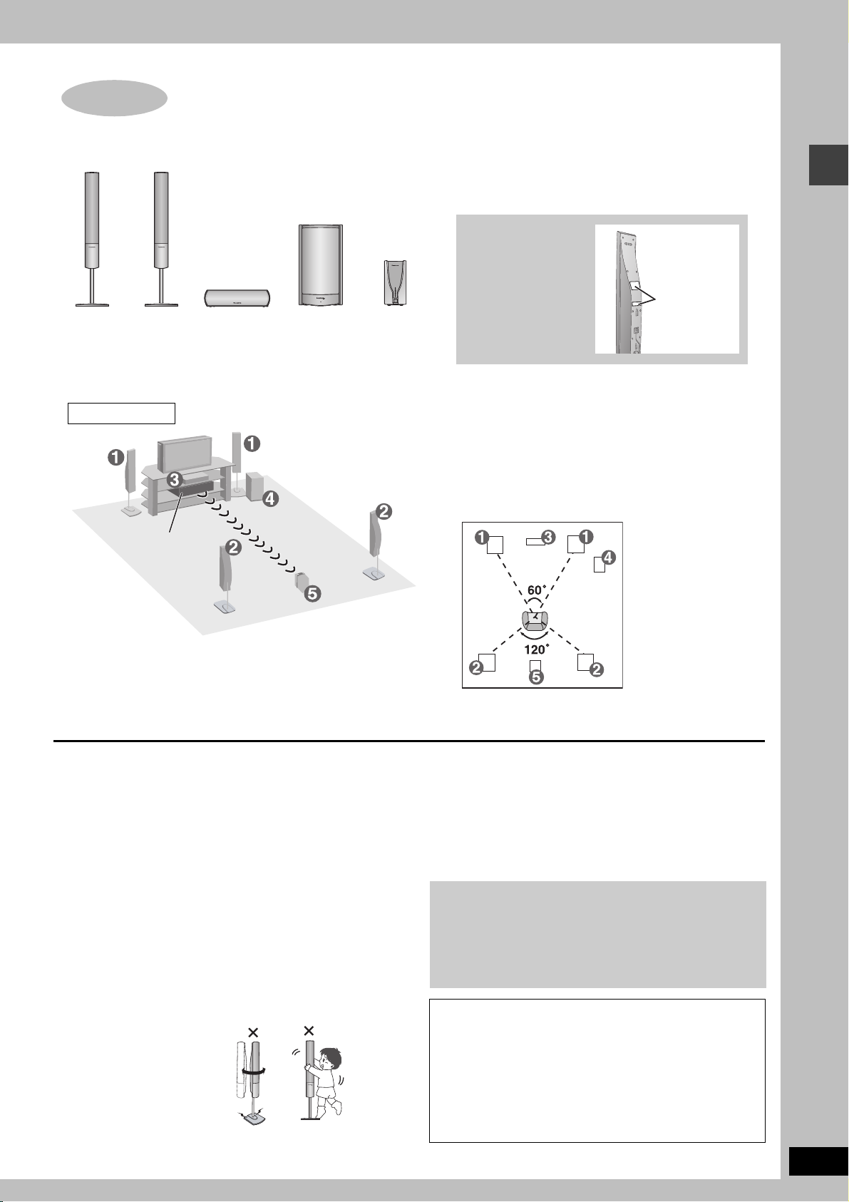
2 Front and 2 Surround
speakers
Pipes
≥2kpipes with short cable: For front speakers
≥2kpipes with long cable: For surround speakers
4 Bases
8 Long screws
8 Short screws
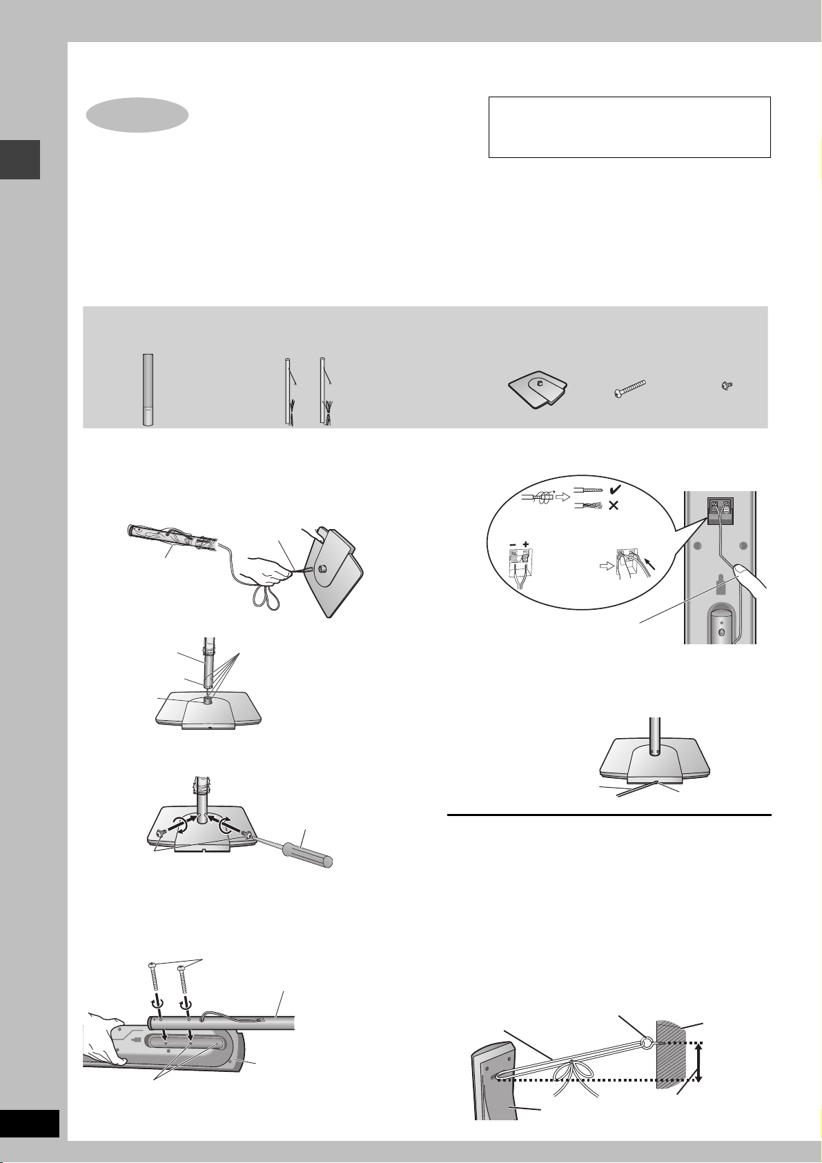
Front and surround speaker assembly
1 Assemble the speaker stands.
1 Thread the speaker cable through the base.
For quicker threading, loosely fold the cable in half (do not
crease), pass the folded portion through the hole, and then pull
the rest of the cable through the base.
Cable
3 Connect the speaker cables.
Rear of the speaker
Twist off the vinyl ends of the
speaker cables.
_: Copper
Plastic wrap
Leave the excess speaker
cable for connecting later.
Base
2 Insert the pipe.
Pipe
Groove
Pipe support
Base
Match the groove and these
holes with the base when you
insert the pipe.
Insert the pipe while gently
pulling on the speaker cable.
3 Secure the pipe to the base.
Ensure the screws are securely fastened.
Phillips-head
screwdriver (not included)
Short screws
Before proceeding to the next step, please remove the plastic
wrap from the pipe.
2 Attach the stands to the speakers.
Ensure the stand is fastened on straight by gradually tightening the
top and bottom screws alternately until fully tightened.
Long screws
Pipe
Press the speaker cable into the
groove.
If there is any excess speaker cable, thread the speaker cable
into the opening near the top of the pipe while pulling the speaker
cable from the bottom of the base.
4 Secure the speaker cables to the bases.
Press the speaker cable into
the base cover groove as far
as possible.
∫ Preventing the speakers from falling over
Preparation
Attach screw eyes (not included) to secure the speakers to the wall
(➜ diagram below).
≥You will need to obtain the appropriate screw eyes to match the
walls or pillars to which they are going to be fastened.
≥Consult a qualified housing contractor concerning the
appropriate procedure when attaching to a concrete wall or a
surface that may not have strong enough support. Improper
attachment may result in damage to the wall or speakers.
1 Thread the string (not included) through the slot on the
rear of the speaker to prevent it from falling over.
2 Loop the string through the screw eye and tie tightly.
String (not included)
`: Silver
Push!
Cable
Screw eye (not included)
Rear side
of base
Groove
Wall
RQT7991
4
Speaker
You can also attach to the lower rear of the speaker.
The height of the speaker can be changed when attaching the
stand to the upper rear or lower rear of the speaker.
Rear of the speaker
Approx. 150 mm
STEP
)
2
1
FRONT
(L, R)
Setup example
SURROUND
Positioning
The left and right speakers are the same
with respect to the front and surround
speaker pairs.
2
(L, R)
3
CENTER
How you set up your speakers can affect the bass and the sound field. Note the following
points:
≥Place speakers on flat secure bases.
≥Placing speakers too close to floors, walls, and corners can result in excessive bass.
Cover walls and windows with thick curtains.
Do not use a front
speaker as a
surround speaker
or vice versa. Verify
AC IN
45
ACTIVE
SUBWOOFER
DIGITAL
RECEIVER
the type of speaker
with the label on
the rear of the front
speaker.
Place the front, center, and surround speakers at
approximately the same distance from the seating position.
The angles in the diagram are approximate.
Speaker labels
Positioning
Main unit
≥Place the digital receiver within approximately 10 m from the main unit.
≥Do not use this wireless system near a microwave oven.
≥Do not place the main unit or receiver in a metal cabinet or bookshelf.
≥Use only supplied speakers
Using other speakers can damage the unit, and sound quality will
be negatively affected.
≥Set the speakers up on an even surface to prevent them from
falling. Take proper precautions to prevent the speakers from
falling if you cannot set them up on an even surface.
Main unit
[Note]
Keep your speakers at least 10 mm away from the system for
proper ventilation.
Center speaker
≥Vibration caused by the center speaker can disrupt the picture if it
is placed directly on the television. Put the center speaker on a
rack or shelf.
≥To prevent the speakers from falling, do not place directly on top
of the television.
Active subwoofer
Place to the right or left of the television, on the floor or a sturdy
shelf so that it won’t cause vibration. Leave 10 cm at the rear for
ventilation.
Caution
Do not stand on the base and
shake the speaker.
Be cautious when children are
near.
Other speaker setup options (➜ page 29
Notes on speaker use
≥You can damage your speakers and shorten their useful life if you
play sound at high levels over extended periods.
≥Reduce the volume in the following cases to avoid damage:
– When playing distorted sound.
– When the speakers are reverberating due to a record player,
noise from FM broadcasts, continuous signals from an
oscillator, test disc, or electronic instrument.
– When adjusting the sound quality.
– When turning the unit on or off.
If irregular coloring occurs on your television
The supplied speakers are designed to be used close to a
television, but the picture may be affected with some televisions
and setup combinations.
If this occurs, turn the television off for about 30 minutes.
The television’s demagnetizing function should correct the
problem. If it persists, move the speakers farther away from the
television.
Caution
≥The active subwoofer, supplied speakers and digital
receiver are to be used only as indicated in this setup.
Failure to do so may lead to damage to the amplifier, the
speakers and/or digital receiver, and may result in the
risk of fire. Consult a qualified service person if damage
has occurred or if you experience a sudden change in
performance.
≥Do not attempt to attach these speakers to walls using
methods other than those described in this manual.
RQT7991
5
STEP
3
Connecting speakers with the subwoofer and the
digital receiver
≥Attach the speaker-cable stickers to make connection easier.
≥The terminals of the subwoofer and the digital receiver have high output power. Carefully connect the speaker wires.
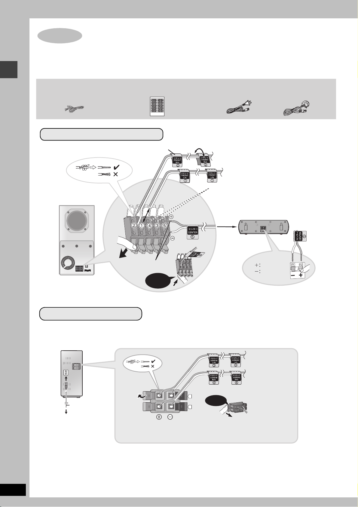
Speaker cable
(For center speaker)
Sheet of speaker-cable stickers
Front and center speaker connection
Speaker-cable sticker
ACTIVE
SUBWOOFER
Click!
AC mains lead
[Australia\and\N.Z.]
2 FRONT (R)
1 FRONT (L)
Connect the surround speaker cables here only if you do
not intend to use the digital receiver (➜ below).
4 SURROUND (R), 3 SURROUND (L)
5 CENTER
[The\United\Kingdom]
Connecting speakers with the subwoofer and the digital receiver
Insert the wire fully.
Click!
Copper
Silver
Surround speaker connection
≥Connect the AC mains lead after speaker cable connections are complete.
DIGITAL
RECEIVER
3 SURROUND (L)
AC IN~
AC mains lead
To household
mains socket
i: Copper
j: Silver
.
4
Click!
4 SURROUND (R)
RQT7991
6
[Note]
≥Never short-circuit positive (i) and negative (j) speaker wires.
≥Be sure to connect only positive (copper) wires to positive (i) terminals and negative (silver) wires to negative (j) terminals. Incorrect
connection can damage the speakers.
≥Do not use more than one pair of surround speakers when using this wireless system.
STEP
COMPONENT VIDEO OUT
S-V IDEO
OUT
VID EO
OUT
(NTSC: 4 80p/480i, P AL: 576p/57 6i)
S-V IDEO
OUT
(NTSC: 4 80p/480i, P AL: 576p/57 6i)
(NTSC: 4 80p/480i, P AL: 576p/57 6i)
(PROGRES SIVE/INTERL ACE)
4
Video connections
≥Do not connect through the video cassette recorder.
Due to copy guard protection, the picture may not be displayed
properly.
≥Turn the television off before connecting, and refer to the
television’s operating instructions.
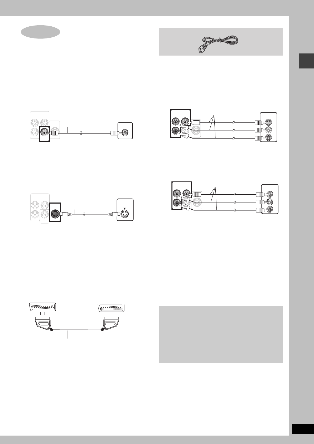
∫ Television with a VIDEO IN terminal
Back of the
main unit
COMPONENT VIDEO OUT
(NTSC: 480p/480i, PAL: 576p/576i)
P
B
Y
S-VIDEO
OUT
P
R
VIDEO
OUT
Video cable
(included)
Television
(not included)
VIDEO IN
Video cable
∫
Television with COMPONENT VIDEO IN terminals
[Australia\and\N.Z.]
Back of the
main unit
COMPONENT VIDEO OUT
(NTSC: 480p/480i, PAL: 576p/576i)
P
B
Y
S-VIDEO
P
R
VIDEO
OUT
Video cables
(not included)
OUT
Television
(not included)
COMPONENT
VIDEO IN
Y
PB
PR
Video connections
∫ Television with an S-VIDEO IN terminal
Back of the
main unit
COMPONENT VIDEO OUT
(NTSC: 480p/480i, PAL: 576p/576i)
P
B
Y
S-VIDEO
P
R
VIDEO
OUT
OUT
S-video cable
(not included)
S-VIDEO OUT terminal
The S-VIDEO OUT terminal achieves a more vivid picture than the
VIDEO OUT terminal by separating the chrominance (C) and
luminance (Y) signals. (Actual results depend on the television.)
[The\United\Kingdom\
Television
(not included)
S-VIDEO
IN
∫ Television with SCART terminal
Back of the
main unit
AV
Scart cable
(not included)
Television
(not included)
AV
[The\United\Kingdom\
Back of the
main unit
COMPONENT VIDEO OUT
(PROGRESSIVE/INTERLACE)
P
B
P
R
VIDEO
OUT
Y
S-VIDEO
Video cables
(not included)
OUT
Television
(not included)
COMPONENT
VIDEO IN
Y
PB
PR
COMPONENT VIDEO OUT terminals
These terminals can be used for either interlace or progressive
output and provide a purer picture than the S-VIDEO OUT
terminal. Connection using these terminals outputs the color
difference signals (P
B/PR) and luminance signal (Y) separately in
order to achieve high fidelity in reproducing colors.
≥The description of the component video input terminals depends
on the television or monitor (e.g. Y/P
B/PR, Y/B-Y/R-Y, Y/CB/CR).
Connect to terminals of the same color.
[The\United\Kingdom]
≥When making this connection, select “Video/YPbPr” or “S-Video/
YPbPr” from QUICK SETUP (➜ page 9). If “RGB/No Output” is
selected, the RGB signal is output from the SCART (AV) terminal,
but no signal is output from the component video output
terminals.
To enjoy progressive video
≥Connect to the component video input terminals on a 576p
(or 625p) or 480p (or 525p) compatible television. (Video will
not be displayed correctly if connected to an incompatible
television.)
[The\United\Kingdom]
≥Panasonic televisions with 625 (576)/50i·50p, 525 (480)/
60i·60p input terminals are progressive compatible. Consult
the manufacturer if you have another brand of television.
SCART (AV) terminal
To improve picture quality, you can change the video signal output
from the SCART (AV) terminal from “Video” to either “S-Video” or
“RGB” to suit the type of television you are using. Select “S-Video/
YPbPr” or “RGB/No Output” from QUICK SETUP (➜ page 9).
RQT7991
7
STEP
VCR
AUDIO
IN
FM ANT
AM ANT
(75
LOO P
EXT
COMPONENT VIDEO OUT
(PROGRESSIV
E/IN
TERLACE)
S-VIDEO
OUT
VIDEO
OUT
AUX
5
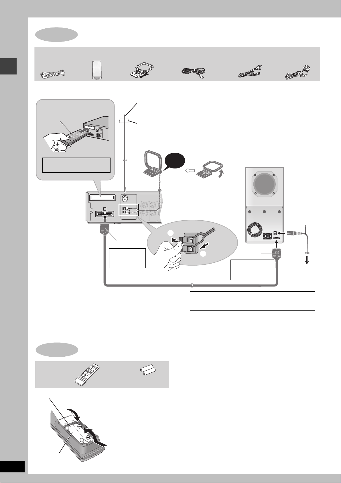
The digital transmitter, radio and system connections
System cable
Digital transmitter
AM loop antenna
FM indoor antenna
≥Connect the AC mains lead after all other connections are complete.
≥Optional antenna connections (➜ page 23).
FM indoor antenna
Digital transmitter
Insert fully until you
Affix this end of the antenna where
reception is best.
hear a click.
Adhesive tape
Do not insert or remove
Click!
while the main unit is on.
COMPONENT VIDEO OUT
(PROGRESSIV
E/IN
P
B
P
R
Main unit
DIGITAL
TRANSMITTER
FM ANT
(75
≠
)
AM ANT
A
LOOP
EXT
L
R
TV
VCR
AUX
AUDIO
AUDIO
IN
IN
AC mains lead
[Australia\and\N.Z.]
AM loop antenna
Stand the antenna up on its base. Place the
antenna where reception is best.
Keep loose antenna cable away from other wires
and cables.
Active subwoofer
TERLACE)
Y
S-VIDEO
OUT
VIDEO
OUT
[The\United\Kingdom]
AC mains lead
The digital transmitter, radio and system connections/The remote control
RQT7991
8
1
Catch up
To disconnect
Press the catch
and pull out.
System cable
Conserving power
The main unit consumes a small amount of power, even when it is turned
off (approx. 0.7 W). To save power when the unit is not to be used for a
long time, unplug it from the household mains socket.
You will need to reset some memory items after plugging in the unit.
[Note]
The included AC mains lead is for use with this unit only. Do not use it with other equipment.
STEP
Remote control Batteries
2
R6/LR6, AA, UM-3
6
Insert so the poles (i and j) match those in the
remote control.
The remote control
3
1
≥Do not use
rechargeable type
batteries.
2
[The\United\Kingdom]
BE SURE TO READ THE CAUTION FOR THE AC
MAINS LEAD ON PAGE 3 BEFORE CONNECTION.
Do not:
≥mix old and new batteries.
≥use different types at the same time.
≥heat or expose to flame.
≥take apart or short circuit.
≥attempt to recharge alkaline or manganese batteries.
≥use batteries if the covering has been peeled off.
Mishandling of batteries can cause electrolyte leakage which can
damage items the fluid contacts and may cause a fire.
Remove if the remote control is not going to be used for a long
period of time. Store in a cool, dark place.
∫ Use
Aim at the remote control signal sensor (➜ page 10), avoiding
obstacles, at a maximum range of 7 m directly in front of the unit.
Catch up
To disconnect
Press the catch
and pull out.
To household
mains socket
STEP
7
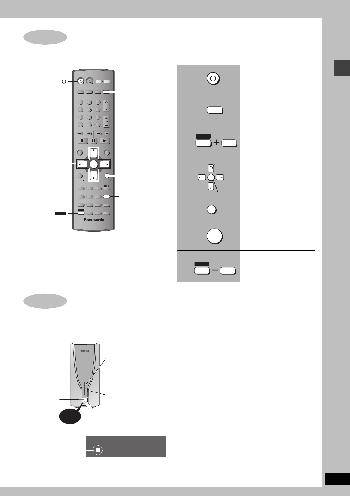
QUICK SETUP
The QUICK SETUP screen assists you to make necessary settings.
Turn on the television and select the appropriate video input on the television.
3, 4, 2, 1
ENTER
SHIFT
AV SYSTEM
TV/AV
12
45
7
CANCEL
SKIP
TOP MENU
DIRECT
NAVIGATOR
FUNCTIONS
SUBWOOFER
SUPER SRND
LEVEL
SLEEP
MANUAL SKIP
QUICK OSD
ANGLE/PAGE
FL DISPLAY REPEAT
ADVANCED
SHIFT
DISC REVIEW
AUX
8
0
ENTER
H.BASS
ZOOM
GROUP
TV
TUNER/BAND
3
6
VOLUME
9
-/--
S10
SLOW/SEARCH
C.FOCUS
SFC
SUBTITLE
AUDIO
PLAY SPEED
QUICK REPLAY
VCR
DVD/ CD
CH
MENU
PLAY
LIST
RETURN
TV VOLTV VOL
MIX 2CH
PL
SETUP
MUTING
PLAY MODE
TEST
CH SELECT
DVD/ CD
RETURN
SETUP
To change these settings later
Select “QUICK SETUP” in the “Others” tab (➜ page 21).
1
2
3
4
5
DVD /CD
SHIFT
ENTER
RETURN
Select
Register
ENTER
SETUP
MUTING
Turn on the main unit.
Select “DVD/CD”.
Show the QUICK
SETUP screen.
Follow the messages
and make the settings.
QUICK SETUP/Turning on the digital receiver
Press to finish QUICK
SETUP.
STEP
8
Turning on the digital receiver
1 Turn on the main unit. (➜ above)
2 Turn on the digital receiver.
Wireless link indicator
This indicator lights
when the signal strength
is adequate for proper
operation.
Power on/off
button
Press!
Power indicator
This indicator lights
when the unit is
turned on.
6
SHIFT
SETUP
MUTING
Press to exit.
[Note]
To save power when your home theater system is not being used,
first turn off the digital receiver followed by the main unit.
“ [W] ” lights up in the
W
display on the main unit.
(“ [W] ” is flashing ➜ page 35, Unit displays)
RQT7991
9
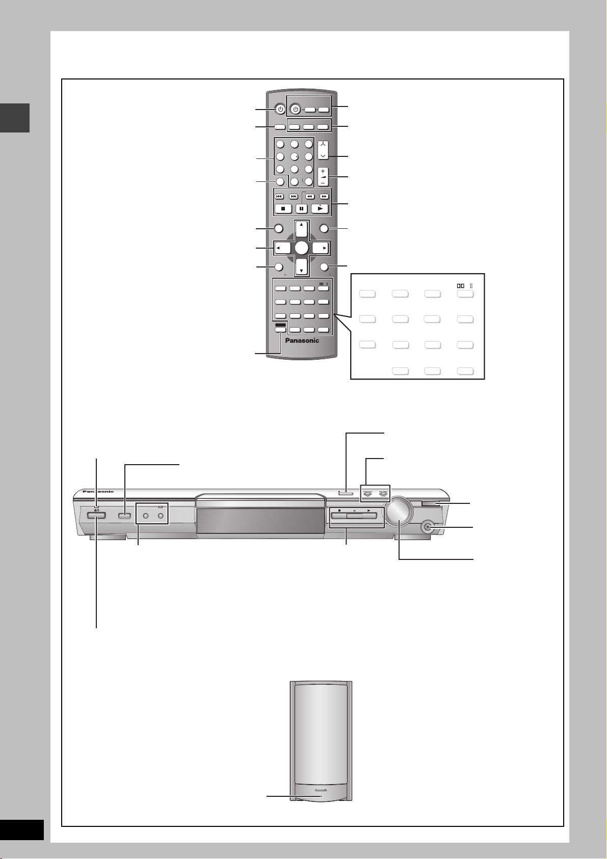
Control reference guide
See reference pages in brackets.
Control reference guide
Turn the unit on/off (9)
Switch the television’s video
input mode (27)
Select television channels and disc’s
title numbers etc./Enter numbers (13)
Cancel (13)
Show a disc top menu (16) or
program list (17)
Select or register menu items on the
television screen, Frame-by-frame (13)
Show on-screen menu (18),
Display RDS text data ([The\United\Kingdom] only) (23)
or television volume down (27)
To use functions labeled in orange:
While pressing [SHIFT],
press the corresponding button.
AV SYSTEM
AUX
TV/AV
12
45
8
7
CANCEL
0
SKIP
TOP MENU
DIRECT
NAVIGATOR
ENTER
FUNCTIONS
SUBWOOFER
SUPER SRND
LEVEL
H.BASS
SLEEP
ZOOM
QUICK OSD
MANUAL SKIP
ANGLE/PAGE
FL DISPLAY REPEAT
GROUP
ADVANCED
SHIFT
DISC REVIEW
TV
TUNER/BAND
3
6
9
-/--
S10
SLOW/SEARCH
C.FOCUS
SFC
SUBTITLE
AUDIO
PLAY SPEED
QUICK REPLAY
VCR
DVD/ CD
CH
VOLUME
MENU
PLAY
LIST
RETURN
TV VOLTV VOL
MIX 2CH
PL
SETUP
MUTING
PLAY MODE
TEST
CH SELECT
Television and Video cassette
recorder operations (27)
Select the source
AUX (27),TUNER/BAND (22),
DVD /CD (9)
Channel select (22, 27)
Adjust the volume (13)
Basic operations for play (12, 13)
Show a disc menu (16) or play list (17)
Return to previous screen (13) or
television volume up (27)
SUBWOOFER
QUICK OSD
(
FL DISPLAY REPEAT
LEVEL
(25)
SLEEP
14, 28
)
(13) (
SUPER SRND
(24, 25)
MANUAL SKIP
ANGLE/PAGE
ADVANCED
DISC REVIEW
C.FOCUS
H.BASS
SFC
(24) (24)
ZOOM
SUBTITLE
AUDI O
(14, 15) (20, 28)
(14)
GROUP
13, 15
)
PLAY SPEED
QUICK REPLAY
(14) (25)
(14, 15)
PLAY MODE
15
)
(
CH SELECT
MIX 2CH
PL
SETUP
MUTING
(15)
TEST
Standby/on indicator
When the unit is connected to the AC mains supply, this
indicator lights up in standby mode and goes out when
the unit is turned on.
INPUT SELECTOR (22)
DVD /CD#FM#AM#TV#VCR#
AUX#Return to DVD/CD
OPENCLOSE
INPUT SELECTOR PROGRESSIVE
Standby/on switch [Í/I]
H.BASS
RDS
PROGRESSIVE
Enjoy progressive video (12)
RDS ([The\United\Kingdom] only)
Display RDS text data (23)
H.BASS
Turn the bass sound enhancement
on/off (25)
H.BASS indicator
TUNE MODE FM MODE MEMORY
∫/TUNE MODE
Stop playing (12)/
Select the tuning mode (22)
;/FM MODE
Pause (12)/Adjust the FM
reception condition (22)
1/MEMORY
Play discs (12)/Memorize the
receiving radio stations (22)
Press to switch the unit from on to standby mode or vice versa.
In standby mode, the unit is still consuming a small amount of power. (12)
<OPEN/CLOSE
Open/Close the disc tray (12)
4, 5/X TUNING W
Skipping or slow-search play (12)/
Select the radio stations (22)
TUNING
VOLUME
PHONES
DOWN
UP
The main unit illustration shows the
model for the United Kingdom.
Remote control
signal sensor
PHONES
Connect
headphones (28)
VOLUM E
Turn up/down
the volume (12)
RQT7991
10
AC supply indicator [AC IN]
AC IN
This indicator lights when the unit is connected to the
AC mains supply.
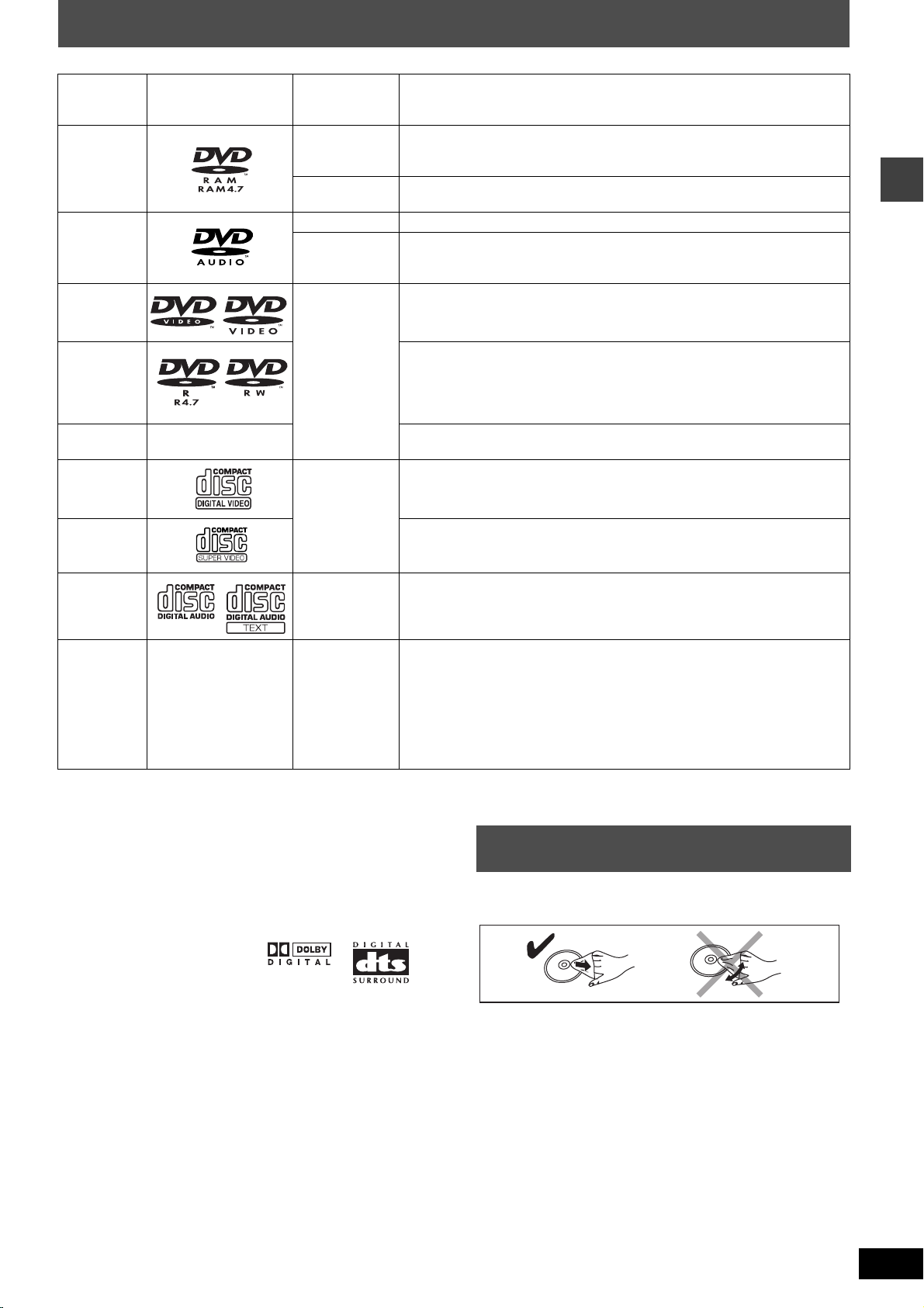
Discs that can be played
Indication in
Disc Logo
DVD-RAM
DVD-Audio
DVD-V ideo
these operating
instructions
[RAM]
[JPEG]
[DVD-A] —
[DVD-V]
Remarks
Recorded with devices using Version 1.1 of the Video Recording Format (a
unified video recording standard), such as DVD video recorders, DVD video
cameras, personal computers, etc.
Recorded using the DCF (Design rule for Camera File system) standard Version 1.0.
≥To play JPEG files, select “Play as Data Disc” in Other Menu (➜ page 19).
Some DVD-Audio discs contain DVD-Video content.
To play DVD-Video content, select “Play as DVD-Video” in Other Menu
(➜ page 19).
—
DVD-R
(DVD-Video)/
DVD-RW
(DVD-Video)
iR (Video)/
iRW (Video)
Video CD
SVCD
CD [CD]
CD-R
CD-RW
§
A process that allows play on compatible equipment.
≥It may not be possible to play the above discs in all cases due to the type of disc or condition of the recording.
—
—
[DVD-V]
[VCD]
[WMA]
[MP3]
[JPEG]
[CD]
[VCD]
Discs recorded and finalized
Discs recorded and finalized§ on DVD video recorders or DVD video cameras.
—
Conforming to IEC62107
This unit is compatible with HDCD, but does not support the Peak Extend
function (a function which expands the dynamic range of high level signals).
HDCD-encoded CD’s sound better because they are encoded with 20 bits, as
compared with 16 bits for all other CD’s.
≥This unit can play CD-R/RW (audio recording disc) recorded with the formats
on the left. Close the sessions or finalize
≥HighMAT discs
WMA, MP3 or JPEG files only.
To play without using the HighMAT function, select “Play as Data Disc” in Other
Menu (➜ page 19).
≥[WMA] This unit does not support Multiple Bit Rate (MBR: a file that contains the
same content encoded at several different bit rates).
§
on DVD video recorders or DVD video cameras.
§
the disc after recording.
Discs that can be played/Disc handling
∫ Discs that cannot be played
DVD-ROM, CD-ROM, CDV, CD-G, SACD, DivX Video Discs and
Photo CD, DVD-RAM that cannot be removed from their cartridge,
2.6-GB and 5.2-GB DVD-RAM and “Chaoji VCD” available on the
market including CVD, DVCD and SVCD that do not conform to
IEC62107.
∫ Audio format of DVD’s
This unit automatically recognizes
and decodes discs with these
symbols.
∫ Video systems
– This unit can play PAL and NTSC, but your television must match
the system used on the disc.
– PAL discs cannot be correctly viewed on an NTSC television.
– This unit can convert NTSC signals to PAL 60 for viewing on a PAL
television (➜ page 21, “NTSC Disc Output” in “Video” tab).
Disc handling
∫ To clean discs
Wipe with a damp cloth and then wipe dry.
∫ Disc handling precautions
≥Do not attach labels or stickers to discs (This may cause disc
warping, rendering it unusable).
≥Do not write on the label side with a ball-point pen or other writing
instrument.
≥Do not use record cleaning sprays, benzine, thinner, static
electricity prevention liquids or any other solvent.
≥Do not use scratch-proof protectors or covers.
≥Do not use the following discs:
– Discs with exposed adhesive from removed stickers or labels
(rented discs, etc.).
– Discs that are badly warped or cracked.
– Irregularly shaped discs, such as heart shapes.
RQT7991
11
 Loading...