

Panasonic SC-HT650P User Manual
R
AV SYSTEM
TV VCR
TV/VIDEO
TUNER/BANDDVD/CD
AUX
DISC
123
DISC 1 DISC 2
DISC 3
PAGE
GROUP
456
DISC 4 DISC 5
DISC
MANAGER
7809
REPEAT
FL DISPLAY
S
10/-/--
PLAY MODE
CANCEL
SKIP
SLOW/SEARCH
CH
TOP MENU
MENU
DIRECT
PLAY LIST
NAVIGATOR
ENTER
DISPLAY
RETURN
TV VOL
s
TV VOL
r
VOLUME
SUBWOOFER
S.POSITION
C.FOCUS
MIX 2CH
LEVEL
SFC
S.SRND
PL
ZOOM
POSITION
SETUP
TIMER
AUDIO
MUTING
MEMORY
TEST
SHIFT
CH SELECT
SUBTITLE
QUICK REPLAY
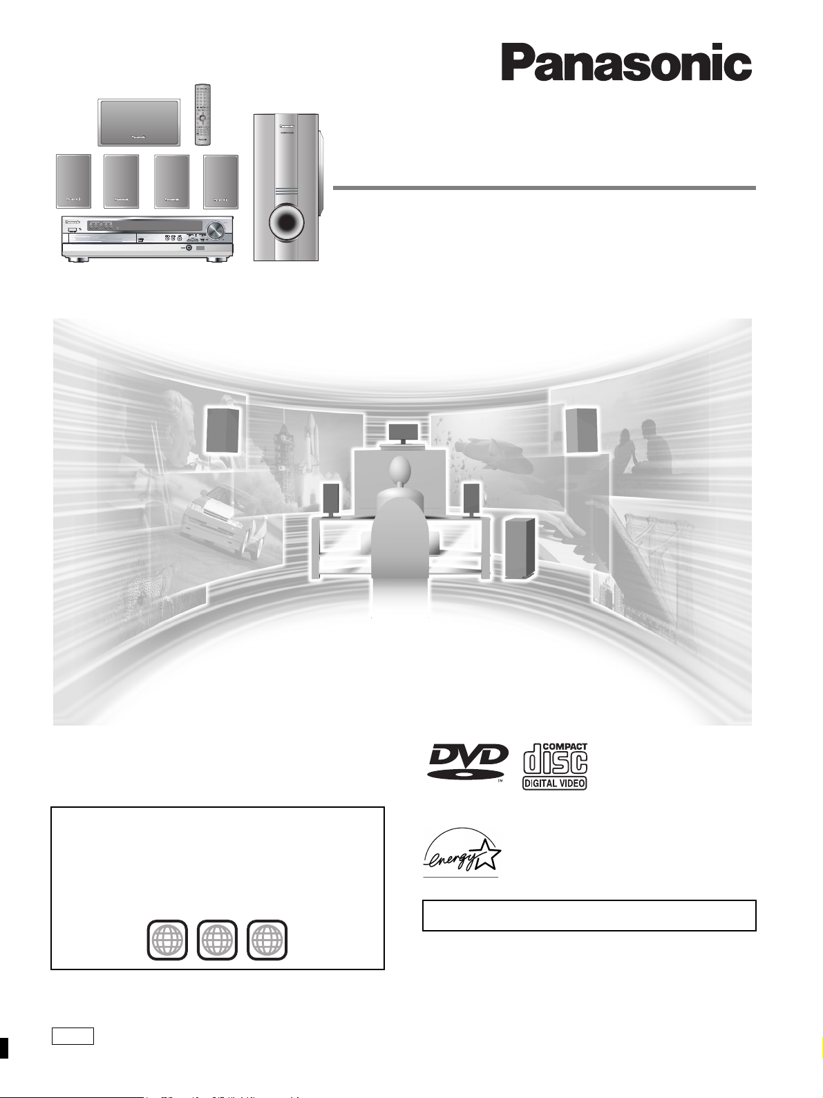
DVD Home Theater Sound System
Operating Instructions
SUBWOOFER LEVEL
TUNING
SFC
SELECTOR
DISCSKIP
Model No. SC-HT650
Before connecting, operating or adjusting this product,
please read these instructions completely.
Please keep this manual for future reference.
Region number supported by this player
Region numbers are allocated to DVD players and software
according to where they are sold.
≥The region number of this player is “1”.
≥The player will play DVD-Video marked with labels containing
“1” or “ALL”.
Example:
1
1 ALL
2
4
P
AUDIO/VIDEO
As an ENERGY STA R® Partner, Panasonic has
determined that this product meets the
TA R® guidelines for energy efficiency.
S
ENERGY
The warranty can be found on page 39.
RQT7089-3P
Dear customer
Thank you for purchasing this product.
For optimum performance and safety, please read these instructions
carefully.
Operations in these instructions are described mainly with
the remote control, but you can do the operations on the
main unit if the controls are the same.
CAUTION!
THIS PRODUCT UTILIZES A LASER.
USE OF CONTROLS OR ADJUSTMENTS OR
PERFORMANCE OF PROCEDURES OTHER THAN THOSE
SPECIFIED HEREIN MAY RESULT IN HAZARDOUS
RADIATION EXPOSURE.
DO NOT OPEN COVERS AND DO NOT REPAIR YOURSELF.
Getting started
REFER SERVICING TO QUALIFIED PERSONNEL.
WARNING:
TO REDUCE THE RISK OF FIRE, ELECTRIC
SHOCK OR PRODUCT DAMAGE, DO NOT
EXPOSE THIS APPARATUS TO RAIN,
MOISTURE, DRIPPING OR SPLASHING AND
THAT NO OBJECTS FILLED WITH LIQUIDS,
SUCH AS VASES, SHALL BE PLACED ON THE
APPARATUS.
CAUTION!
DO NOT INSTALL OR PLACE THIS UNIT IN A BOOKCASE,
BUILT-IN CABINET OR IN ANOTHER CONFINED SPACE.
ENSURE THE UNIT IS WELL VENTILATED. TO PREVENT
RISK OF ELECTRIC SHOCK OR FIRE HAZARD DUE TO
OVERHEATING, ENSURE THAT CURTAINS AND ANY
OTHER MATERIALS DO NOT OBSTRUCT THE
VENTILATION VENTS.
CAUTION
RISK OF ELECTRIC SHOCK
DO NOT OPEN
CAUTION: TO REDUCE THE RISK OF ELECTRIC
SHOCK, DO NOT REMOVE SCREWS.
NO USER-SERVICEABLE PARTS
INSIDE.
REFER SERVICING TO QUALIFIED
SERVICE PERSONNEL.
System SC-HT650
Main unit SA-HT650
Front and Surround
speakers
Center speaker SB-PC650
Subwoofer SB-W650
SB-AFC650
(Inside of product)
CAUTION:
This equipment has been tested and found to comply with the
limits for a Class B digital device, pursuant to Part 15 of the FCC
Rules.
These limits are designed to provide reasonable protection
against harmful interference in a residential installation. This
equipment generates, uses and can radiate radio frequency
energy and, if not installed and used in accordance with the
instructions, may cause harmful interference to radio
communications. However, there is no guarantee that
interference will not occur in a particular installation. If this
equipment does cause harmful interference to radio or
television reception, which can be determined by turning the
equipment off and on, the user is encouraged to try to correct
the interference by one or more of the following measures:
≥Reorient or relocate the receiving antenna.
≥Increase the separation between the equipment and receiver.
≥Connect the equipment into an outlet on a circuit different from
that to which the receiver is connected.
≥Consult the dealer or an experienced radio/TV technician for
help.
Any unauthorized changes or modifications to this equipment
would void the user’s authority to operate this device.
This device complies with Part 15 of the FCC Rules. Operation
is subject to the following two conditions: (1) This device may
not cause harmful interference, and (2) this device must accept
any interference received, including interference that may cause
undesired operation.
RQT7089
2
The lightning flash with arrowhead symbol, within
an equilateral triangle, is intended to alert the user
to the presence of uninsulated “dangerous voltage”
within the product’s enclosure that may be of sufficient magnitude to constitute a risk of electric shock
to persons.
The exclamation point within an equilateral triangle
is intended to alert the user to the presence of
important operating and maintenance (servicing)
instructions in the literature accompanying the appliance.
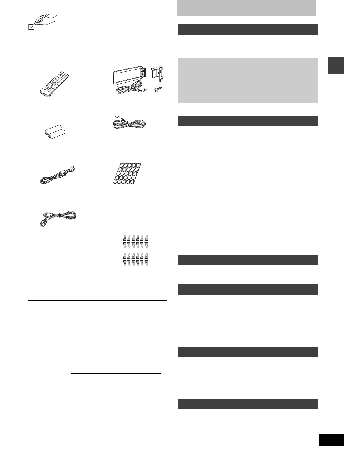
Accessories
Please check and identify the supplied accessories.
Use numbers indicated in parentheses when asking
for replacement parts.
To order accessories contact 1-800-332-5368 or
the website (http://www.panasonic.com).
∏ 1 Remote control
(EUR7623XD0)
∏ 2 Batteries
for remote control
∏ 1 AC power supply cord
(RJA0065-1D)
∏ 1 Video cable
(RJL1P016B15A)
[Note]
The included AC power supply cord is for use with this unit only. Do
not use it with other equipment.
User memo:
DATE OF PURCHASE ______________________________
DEALER NAME ___________________________________
DEALER ADDRESS ________________________________
_________________________________________________
TELEPHONE NUMBER _____________________________
The model number and serial number of this product can be
found on either the back or the bottom of the unit.
Please note them in the space provided below and keep for
future reference.
MODEL NUMBER
SERIAL NUMBER
∏ 1 AM loop antenna set
(RSA0012-L)
∏ 1 FM indoor antenna
(RSA0006-J)
∏ 1 Sheet of speaker feet
(RFA0631A-K)
Replacements sold in
sets of 4.
∏ 1 Sheet of speaker-cord
stickers
(12 stickers)
One set is extra.
The sheet cannot be
purchased separately.
6
SUBWOOFER
CENTER
SUBWOOFER
5
6
6
SUBWOOFER
CENTER
SUBWOOFER
5
6
FRONT L
FRONT R
SURROUND L
SURROUND R
CENTER
FRONT L
FRONT R
SURROUND L
SURROUND R
1
2
3
4
1
2
3
4
5
FRONT L
FRONT R
SURROUND L
SURROUND R
CENTER
FRONT L
FRONT R
SURROUND L
SURROUND R
1
2
3
4
1
2
3
4
5
SC-HT650
Table of contents
Getting started
Accessories . . . . . . . . . . . . . . . . . . . . . . . . . . . . . . . . . . . . 3
IMPORTANT SAFETY INSTRUCTIONS . . . . . . . . . . . . . . 4
Disc information . . . . . . . . . . . . . . . . . . . . . . . . . . . . . . . . 5
Simple setup
STEP1 Locating. . . . . . . . . . . . . . . . . . . . . . . . . . . . . 6
STEP2 Speakers . . . . . . . . . . . . . . . . . . . . . . . . . . . . 7
STEP3 Television . . . . . . . . . . . . . . . . . . . . . . . . . . . 8
STEP4 Antennas and AC power supply cord. . . . . 9
STEP5 The remote control . . . . . . . . . . . . . . . . . . . . 9
STEP6 QUICK SETUP . . . . . . . . . . . . . . . . . . . . . . . 10
Control reference guide . . . . . . . . . . . . . . . . . . . . . . . . . 11
Disc operations
Discs—Basic play . . . . . . . . . . . . . . . . . . . . . . . . . . . . . . 12
Using the disc manager/Position Memory function . . . . . . . . . .13
Replaying a scene—QUICK REPLAY . . . . . . . . . . . . . . . . . . . . 14
Starting play from a selected item . . . . . . . . . . . . . . . . . . . . . . .14
Selecting still pictures—Page Skip . . . . . . . . . . . . . . . . . . . . . .14
Skipping items/Fast forward and rewind—SEARCH . . . . . . . . . 14
Slow-motion play/Frame-by-frame viewing . . . . . . . . . . . . . . . .14
Discs—Convenient functions. . . . . . . . . . . . . . . . . . . . . 15
Selecting groups to play. . . . . . . . . . . . . . . . . . . . . . . . . . . . . . .15
Repeat play/A-B repeat play . . . . . . . . . . . . . . . . . . . . . . . . . . .15
Soundtracks/Subtitles . . . . . . . . . . . . . . . . . . . . . . . . . . . . . . . . 16
All group play/Program play/Random play. . . . . . . . . . . . . . . . .17
Marking places to play again . . . . . . . . . . . . . . . . . . . . . . . . . . .18
Variable Zoom function . . . . . . . . . . . . . . . . . . . . . . . . . . . . . . .18
Playing the programs or play lists on DVD-RAM . . . . . 19
Selecting a program to play—DIRECT NAVIGATOR . . . . . . . . 19
Using the play list menu. . . . . . . . . . . . . . . . . . . . . . . . . . . . . . . 19
WMA/MP3, CD text and JPEG navigation menus . . . . . 20
Playing HighMAT discs . . . . . . . . . . . . . . . . . . . . . . . . . . . . . . . 21
Using On-Screen Menu Icons. . . . . . . . . . . . . . . . . . . . . 22
Common procedures/Progress indicator . . . . . . . . . . . . . . . . . .22
Disc information/Unit information . . . . . . . . . . . . . . . . . . . . . . . .23
Radio operations
The radio. . . . . . . . . . . . . . . . . . . . . . . . . . . . . . . . . . . . . . 25
Manual tuning/Preset tuning . . . . . . . . . . . . . . . . . . . . . . . . . . . 25
Sound field/sound quality operations
Sound field . . . . . . . . . . . . . . . . . . . . . . . . . . . . . . . . . . . . 26
Dolby Digital and DTS/Dolby Pro Logic . . . . . . . . . . . . . . . . . . . 26
Speaker level adjustments . . . . . . . . . . . . . . . . . . . . . . . . . . . . . 26
Super Surround/Sound Field Control . . . . . . . . . . . . . . . . . . . . .27
Center Focus/Seat Position . . . . . . . . . . . . . . . . . . . . . . . . . . . .27
Sound quality. . . . . . . . . . . . . . . . . . . . . . . . . . . . . . . . . . 28
Adjusting the bass . . . . . . . . . . . . . . . . . . . . . . . . . . . . . . . . . . .28
Double re-master—Enjoying more natural sound . . . . . . . . . . .28
Other functions
Convenient functions . . . . . . . . . . . . . . . . . . . . . . . . . . . 29
Muting the volume/Turning off the display . . . . . . . . . . . . . . . . . 29
Timer functions/Using headphones . . . . . . . . . . . . . . . . . . . . . .29
Operating other equipment. . . . . . . . . . . . . . . . . . . . . . . 30
Changing settings . . . . . . . . . . . . . . . . . . . . . . . . . . . . . . 32
Optional antenna connections. . . . . . . . . . . . . . . . . . . . 34
Getting started
Reference
Glossary . . . . . . . . . . . . . . . . . . . . . . . . . . . . . . . . . . . . . . 35
Maintenance. . . . . . . . . . . . . . . . . . . . . . . . . . . . . . . . . . . 35
Specifications . . . . . . . . . . . . . . . . . . . . . . . . . . . . . . . . . 36
Troubleshooting guide . . . . . . . . . . . . . . . . . . . . . . . . . . 37
Limited Warranty . . . . . . . . . . . . . . . . . . . . . . . . . . . . . . . 39
Product Service . . . . . . . . . . . . . . . . . . . . . . . . Back cover
RQT7089
3
IMPORTANT SAFETY INSTRUCTIONS
Read these operating instructions carefully before using the unit. Follow the safety instructions on the unit and the safety precautions listed below.
Keep these operating instructions handy for future reference.
Getting started
RQT7089
4
Safety
1. Power source—Connect the unit to a power source of the type
described in these instructions or as marked on the unit.
2. Polarization—The unit is equipped with a polarized power plug
where one blade is wider than the other. This safety feature
ensures that the plug fits into your household AC outlet only one
way. If the plug doesn’t fit one way, try reversing it. If the plug still
doesn’t fit, contact an electrician to replace the obsolete outlet.
Do not attempt to defeat the safety purpose of the plug.
3. Power cord protection—Route the AC power supply cord so
that it will not be walked on or pinched by items placed on or
against it. Never take hold of the plug or cord with wet hands.
Always grasp the plug body firmly when connecting and
disconnecting it.
4. Overloading—When connecting the AC power supply cord, be
careful not to overload the household AC outlet, extension cord,
or outlet from any other device as this can result in fire or electric
shock.
5. Nonuse periods—Turn the unit off when it is not in use. Unplug
the unit from the household AC outlet if it is not to be used for a
long time. Unplug the unit during lightning storms.
6. Attachments and accessories—Use only the attachments and
accessories recommended in these operating instructions.
Installation
Placement
1. Ventilation—Situate the unit so that it receives proper
ventilation. Do not install in a confined space such as a bookcase
or cabinet. Allow at least 10 cm (4 inches) clearance from the
rear of the unit. To prevent the risk of electric shock or fire due to
overheating ensure curtains and other materials do not obstruct
the unit’s ventilation.
2. Foreign material—Ensure objects and liquids do not get into the
unit. Avoid exposing the unit to excessive smoke, dust,
mechanical vibration, and shock.
3. Magnetism—Situate the unit away from equipment and devices
that generate strong magnetic fields.
4. Stacking—Do not place heavy objects on top of this unit.
5. Surface—Place the unit on a flat, level surface.
6. Carts and stands—Use the unit only with carts
and stands recommended by the manufacturer.
Move carts with care. Sudden stops, excessive
force, and uneven surfaces can cause carts to
overturn.
7. Wall and ceiling mounting—Do not mount the
unit on walls or ceilings unless specified in the instructions.
Environment
1. Water and moisture—Do not use the unit near water, such as
near a bathtub or swimming pool. Avoid damp basements.
2. Heat—Situate the unit away from heat sources, such as
radiators.
Do not situate where temperatures fall below 5oC (41oF) or rise
above 35oC (95oF).
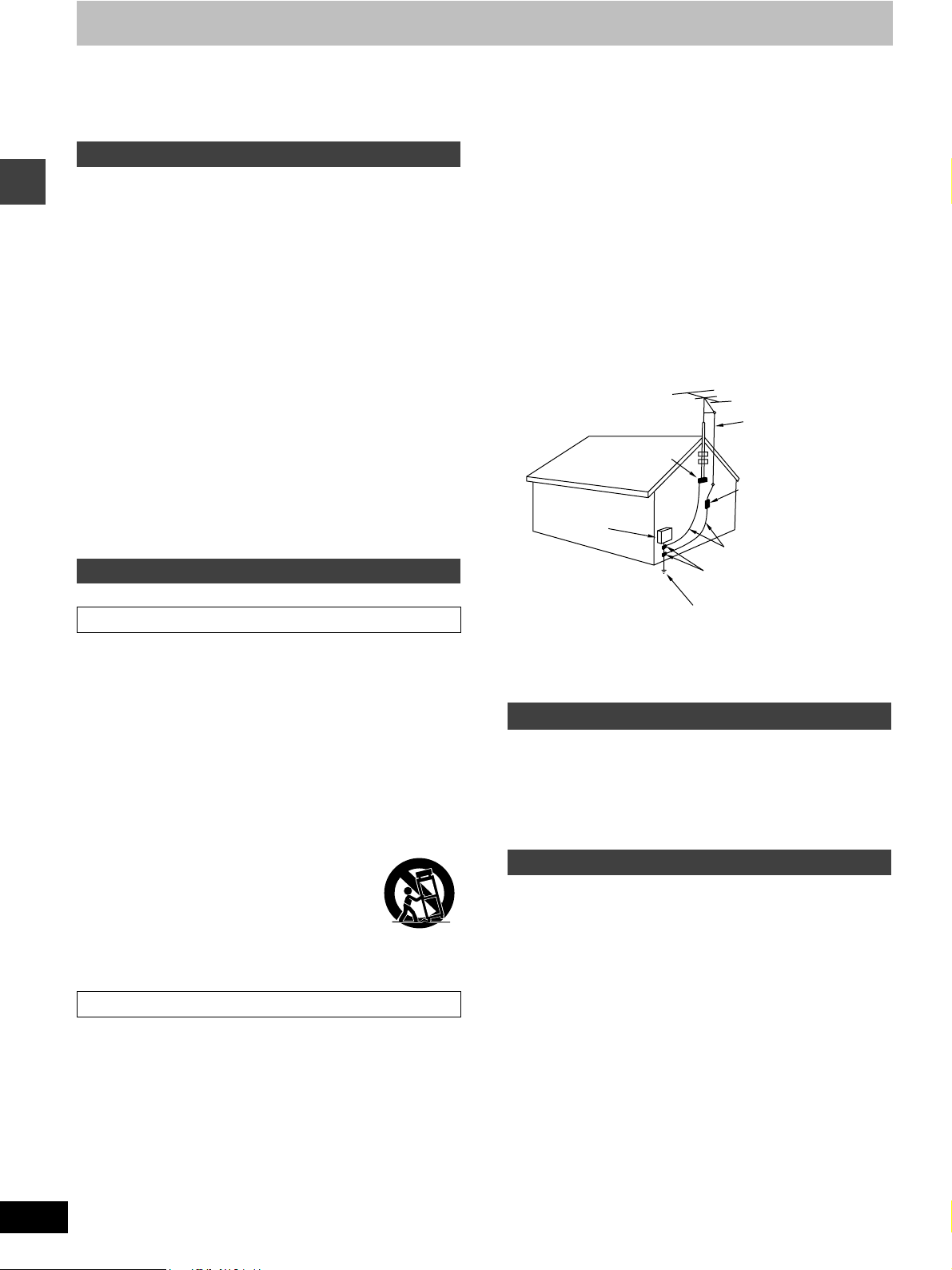
3. Power lines—Take care when setting up an outdoor antenna
that it is not near overhead power lines, electric lights, or
electrical circuits, and that there is no danger of the antenna
falling on power lines, electric lights, or electrical circuits. When
installing an outdoor antenna, take extreme care not to touch
such power lines or circuits, as contact with them can be fatal.
4. Outdoor antenna grounding—If you connect an outdoor
antenna, ground the antenna system to protect against voltage
surges and built-up static charges. Section 810 of the National
Electrical Code, ANSI/NFPA No. 70-1990, provides information
about grounding of the mast and supporting structure, grounding
of the lead-in wire to an antenna discharge unit, size of grounding
conductors, location of antenna-discharge unit, connection to
grounding electrodes, and requirements for the grounding
electrode. Refer to this diagram.
ANTENNA
LEAD IN
GROUND
CLAMP
ELECTRIC
SERVICE
EQUIPMENT
POWER SERVICE GROUNDING
ELECTRODE SYSTEM
(NEC ART 250, PART H)
WIRE
ANTENNA
DISCHARGE UNIT
(NEC SECTION 810-20)
GROUNDING CONDUCTORS
(NEC SECTION 810-21)
GROUND CLAMPS
NEC—NATIONAL ELECTRICAL CODE
Maintenance
(See page 35 for details.)
Unplug the unit from the household AC outlet before cleaning.
Clean with a damp cloth.
Do not use abrasive pads, scouring powders, or solvents.
Service
1. Damage requiring service—The unit should be serviced by
qualified service personnel if:
(a)The AC power supply cord or the plug has been damaged; or
(b)Objects or liquids have gotten into the unit; or
(c)The unit has been exposed to rain; or
(d)The unit does not operate normally or exhibits a marked
change in performance; or
(e)The unit has been dropped or the cabinet damaged.
2. Servicing—Do not attempt to service the unit beyond that
described in these operating instructions. Refer all other
servicing to authorized servicing personnel.
3. Replacement parts—When parts need replacing ensure the
servicer uses parts specified by the manufacturer or parts that
have the same characteristics as the original parts. Unauthorized
substitutes may result in fire, electric shock, or other hazards.
4. Safety check—After repairs or service, ask the servicer to
perform safety checks to confirm that the unit is in proper working
condition.
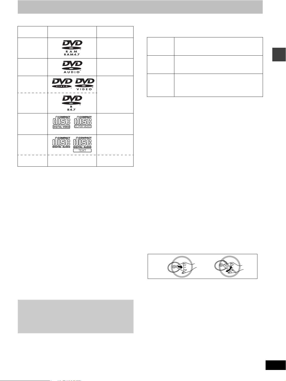
Disc information
∫ Discs that can be played
Disc type Logo Indication used
DVD-RAM [RAM]
DVD-Audio [DVD-A]
DVD-Video [DVD-V]
DVD-R
Video CD [VCD]
CD [CD]
CD-R/RW — [WMA] [MP3]
≥Use discs with the above logos and that conform to specifications.
The unit cannot play other discs correctly.
≥Do not use irregularly shaped discs (e.g. heart-shaped), as these
can damage the unit.
in instructions
Including SVCD
(Confirming to
IEC62107)
Including CD text
[JPEG]
∫ Discs that cannot be played
PAL discs (except DVD-Audio), DVD-ROM, CD-ROM, CDV, CD-G,
iRW, DVD-RW, SACD, Divx Video Discs, Photo CD and “Chaoji
VCD” available on the market including CVD, DVCD and SVCD that
do not conform to IEC62107.
∫ Disc structure
Disc structure and the labels given to the items on discs depend on
the disc type.
Track: the smallest division on DVD-Audio, CDs and Video CDs,
Chapter: the smallest division on DVD-Video.
Group: collections of tracks on DVD-Audio and equivalent to
Title:
Program: the division on DVD-RAM equivalent to a single
Picture: a single JPEG file.
Play list: the largest grouping on a HighMAT disc, or a group of
Scene: DVD-RAM program sections specified and grouped into
Content: covers tracks and pictures on HighMAT discs.
or a single WMA/MP3 file.
folders or albums on data discs.
the largest division on DVD-Video, usually an entire movie.
recording.
scenes on DVD-RAM.
play lists on a DVD video recorder.
Playing DVDs and Video CDs
The producer of these discs can control how they are played so
you may not always be able to control play as described in these
operating instructions (for example if the play time is not
displayed or if a Video CD has menus). Read the disc’s
instructions carefully.
∫ DVD-RAM discs
DVD-RAM discs must meet the following conditions for this unit to be
able to play them.
Ty p e ≥Non-cartridge discs
≥Discs that can be removed from their
cartridges (TYPE 2 and 4)
Capacity ≥12 cm (5q) 9.4 GB (double-sided) and 4.7 GB
Recording
format
≥Remove TYPE 2 and 4 discs from their cartridges before use, then
return them when you are finished. Read the instructions for the
disc carefully.
≥Do not allow the disc to become dirty or scratched. Store discs in
their cartridges and ensure the disc label and cartridge label face
the same way.
≥Some parts of the disc, for example where one program ends and
another begins, may not play smoothly.
(single-sided)
≥8 cm (3q) 2.8 GB (double-sided)
Discs recorded with DVD video recorders, DVD
video cameras, personal computers, etc., using
Version 1.1 of the Video Recording Format (a
unified video recording standard).
∫ DVD-R discs
Panasonic DVD-R recorded and finalized on a Panasonic DVD video
recorder are played as DVD-Video on this unit.
∫ CD-R and CD-RW discs
This unit can play CD-R/RW (audio recording disc) recorded with
CD-DA, video CD, SVCD (conforming to IEC62107), WMA, MP3 or
JPEG. Close the sessions or finalize the disc after recording.
∫ HighMAT discs
This unit is compatible with HighMAT discs containing WMA, MP3,
and/or JPEG files.
[Note]
It may not be possible to play CD-R, CD-RW, DVD-R and DVD-RAM
in all cases due to the type of disc or condition of the recording.
∫ Playing PAL system DVD-Audio
This unit converts PAL to NTSC for play. The picture is compressed
to show it in its entirety, but this may cause it to be stretched
vertically.
∫ To clean discs
DVD-Audio, DVD-Video, Video CD, CD
Wipe with a damp cloth and then wipe dry.
DVD-RAM, DVD-R
≥Clean with an optional DVD-RAM/PD disc cleaner (LF-K200DCA1,
where available).
≥Never use cloths or cleaners for CDs etc.
∫ Handling precautions
≥Do not write on the label side with a ball-point pen or other writing
instrument.
≥Do not use record cleaning sprays, benzine, thinner, static
electricity prevention liquids or any other solvent.
≥Do not attach labels or stickers to discs. (Do not use discs with
exposed adhesive from tape or left over peeled-off stickers.)
≥Do not use scratch-proof protectors or covers.
≥Do not use discs printed with label printers available on the market.
Getting started
RQT7089
5
Simple setup
Sheet of speaker feet
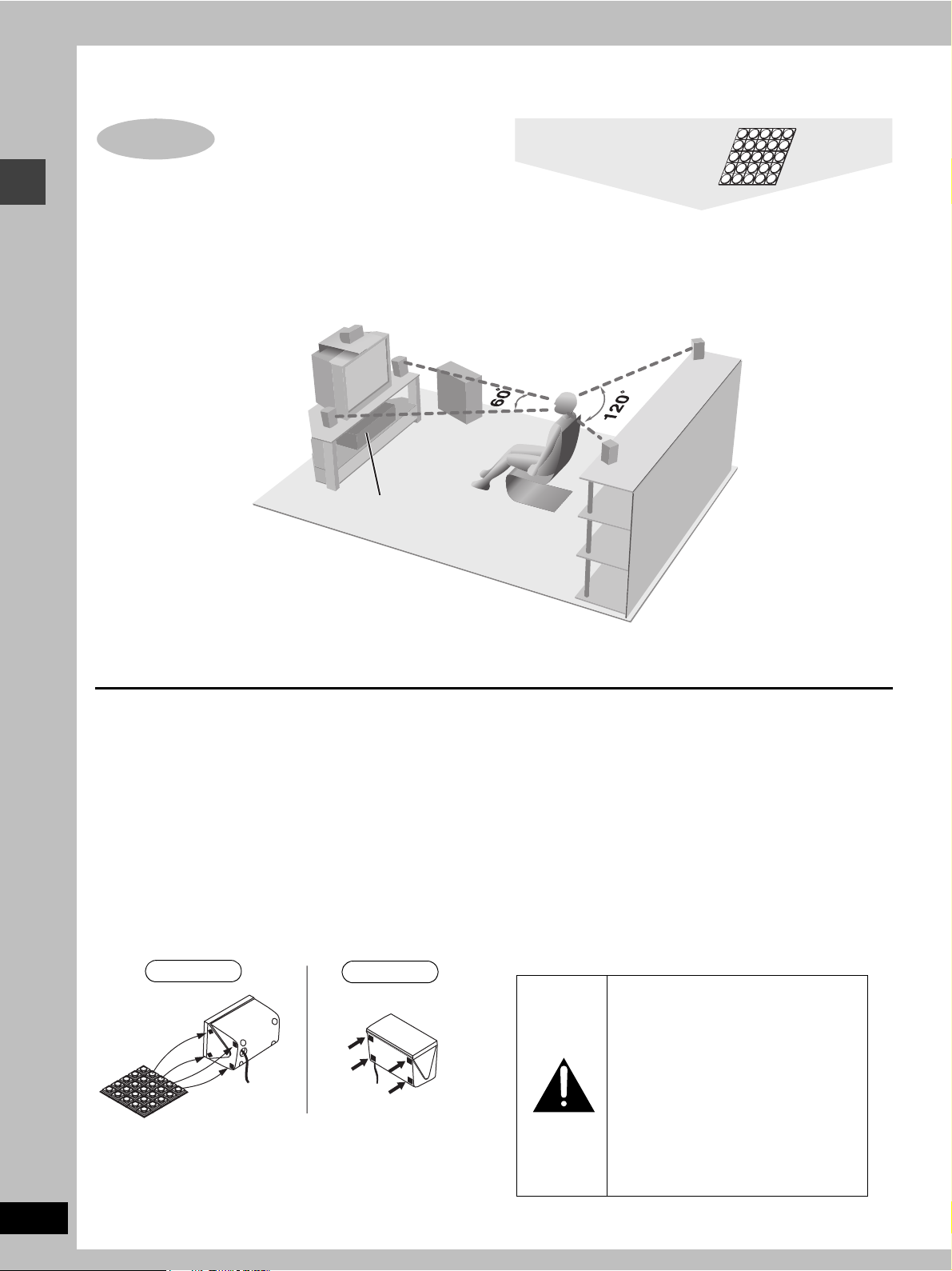
STEP1 Locating
Use only supplied speakers
Using other speakers can damage the unit and sound quality will be negatively affected.
Set the speakers up on an even surface to prevent them from falling. Take proper precautions to prevent the speakers from falling if you cannot
set them up on an even surface.
Setup example
(L)
CENTER
FRONT
Main unit
(R)
SUBWOOFER
SURROUND
(R)
SURROUND
(L)
Simple setup
FRONT
RQT7089
6
≥The front and surround speakers are the same. The left and right speakers are the same.
≥Place the front, center, and surround speakers at approximately the same distance from the seating position. The angles in the diagram are
approximate.
Main unit
Note
Keep your speakers at least 10 mm (
for proper ventilation.
13
/32q) away from the system
Center speaker
≥You can also put this speaker directly under the television.
≥Vibration caused by the center speaker can disrupt the picture if it
is placed directly on the television. Put the center speaker on a
rack or shelf.
Subwoofer
Place to the right of the television, on the floor or a sturdy shelf so
that it won’t cause vibration.
Leave 10 cm (4q) on the right for the woofer to be effective. Leave
10 cm (4q) at the rear for ventilation.
Attaching the speaker feet
Attach these speaker feet to prevent vibration causing the
speakers to move or fall over.
Standing
Front and Surround
speakers
Laying down
Center speaker
Positioning for best effect
How you set up your speakers can affect the bass and the sound
field. Note the following points.
≥Place speakers on flat secure bases.
≥Placing speakers too close to floors, walls, and corners can result
in excessive bass. Cover walls and windows with thick curtain.
Notes on speaker use
≥You can damage your speakers and shorten their useful life if you
play sound at high levels over extended periods.
≥Reduce the volume in the following cases to avoid damage.
–When playing distorted sound.
–When the speakers are receiving howling from a record player,
noise from FM broadcasts, or continuous signals from an
oscillator, test disc, or electronic instrument.
–When adjusting the sound quality.
–When turning the unit on or off.
If irregular coloring occurs on your television
These speakers are designed to be used close to a television, but
the picture may be affected with some televisions and setup
combinations.
If this occurs, turn the television off for about 30 minutes.
The television’s demagnetizing function should correct the problem.
If it persists, move the speakers further away from the television.
Caution
≥Use the speakers only with the
recommended system. Failure to do
so may lead to damage to the
amplifier and/or the speakers, and
may result in the risk of fire. Consult
a qualified service person if damage
has occurred or if you experience a
sudden change in performance.
≥Do not attempt to attach these
speakers to walls using methods
other than those described in this
manual.
6
C
)
A
w
SUBWOOFER
CENTER
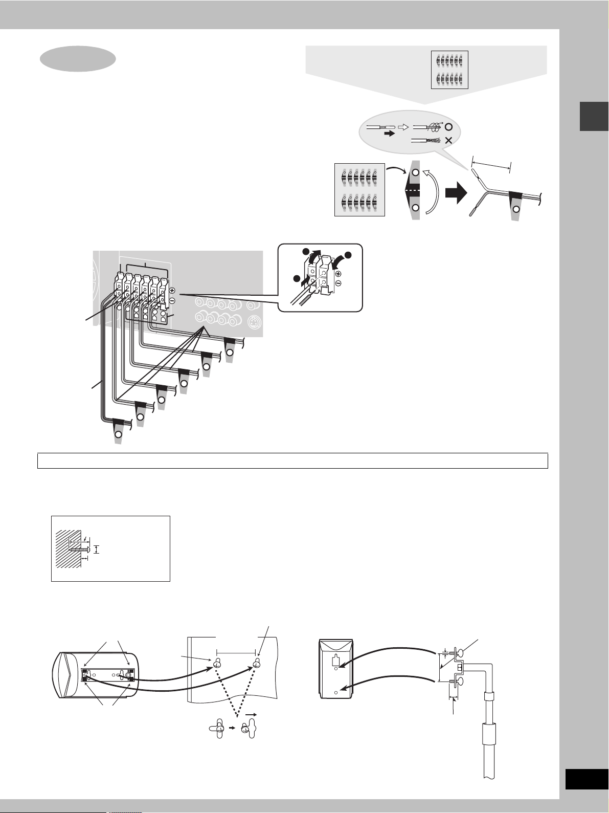
STEP2 Speakers
Sheet of speaker-cord
stickers
SUBWOOFER
6
6
SUBWOOFER
CENTER
SUBWOOFER
6
[1] Attaching the stickers to the speaker cords
Attach the stickers to the speaker cords.
Attach the numbered stickers to the end of the speaker cords so the
numbers match the positions of the speakers shown in the diagram.
FRONT L
1
FRONT L
1
SUBWOOFER
SUBWOOFER
1
2
3
4
5
6
1
2
3
4
5
6
FRONT L
FRONT R
SURROUND L
SURROUND R
CENTER
SUBWOOFER
FRONT L
FRONT R
SURROUND L
SURROUND R
CENTER
1
2
3
4
5
6
1
2
3
4
5
6
FRONT L
FRONT R
SURROUND L
SURROUND R
CENTER
SUBWOOFER
FRONT L
FRONT R
SURROUND L
SURROUND R
CENTER
[2] Connecting the speakers
Connect the cords to the terminals of same color so the numbers on the stickers match the numbers under the terminals.
Black
+ Red
- Black
Red
6
5
4
R
CENTER
SUBWOOFER
C
S
U
B
W
O
O
F
E
R
6
SUBWOOFER
Gray
3
L
SU
R
R
O
U
N
E
N
T
E
R
5
CENTER
2
Blue
1
R
L
D
FRONT
S
U
R
R
O
U
N
3
S
U
R
R
O
U
N
D
R
4
SURROUND (R)
+ Gray (no stripe)
- Gray with blue stripe
F
R
O
N
T
L
1
F
R
O
N
T
R
2
D
L
FRONT (L)
FRONT (R)
SURROUND (L)
1
2
3
After you have completed setup and connection, wind the
excess cord and keep together with string.
[Note]
≥Never short-circuit positive (i) and negative (j) speaker
wires.
≥Be sure to connect only positive (red or gray) wires to
positive (i) terminals and negative (black or gray with blue
stripe) wires to negative (j) terminals.
Incorrect connection can damage the speakers.
1
2
3
4
5
FRONT L
FRONT R
SURROUND L
SURROUND R
CENTER
FRONT L
FRONT R
SURROUND L
SURROUND R
1
2
3
4
5
1
2
3
4
5
FRONT L
FRONT R
SURROUND L
SURROUND R
CENTER
FRONT L
FRONT R
SURROUND L
SURROUND R
1
2
3
4
5
About 10 cm (4")
FRONT L
1
Simple setup
Other speaker setup options
∫ Attaching to a wall
Attach four speaker feet to each speaker, ensuring they do not
cover hole.
1 Screw a screw (not included) into the wall.
30–35 mm
3
(1
/16q–13/8q)
‰7.5–9.5 mm
19
/64q–3/8q)
(
7-9 mm
9
(
/32q–23/64q)
2 Fit the speaker securely onto the screw with the hole or holes.
enter speaker (SB-PC650
Speaker feet
(included)
Screw
(not
included)
Speaker feet
(included)
Front and Surround speakers (SB-AFC650)
The method for attaching speakers to a wall is the same except
that there is only one bracket.
Screw
(not included)
106 mm
11
/64q)
(4
[Note]
The wall or pillar on which the speakers are to be attached should
be capable of supporting 10 kg (22 Ib.) for SB-PC650 and 5 kg
(11 lb.) for SB-AFC650 per screw.
∫ Fitting speaker stands (optional)
Preparation
Ensure the stands meet these conditions before purchasing them.
≥Observe the diameter and length of the screws and the distance
between screws as shown in the diagram.
≥The stands must be able to support over 10 kg (22 lb.) for SB-PC
650 and 5 kg (11 lb.) for SB-AFC650.
≥The stands must be stable even if the speakers are in a high
position.
5 mm (13/64q),
ttach the stands
ith these holes.
pitch 0.8 mm
1
(
/32q)
Plate thickness plus 7 to
10 mm (plus
9
/32q to 25/64q)
Speaker stand
(not included)
60 mm (2
23
/64q)
RQT7089
7
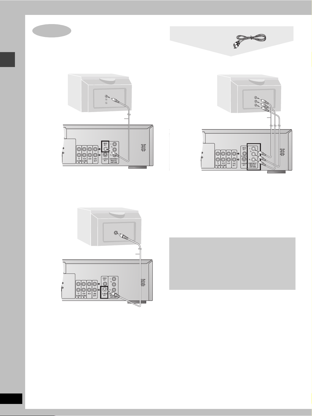
STEP3 Television
Video cable
∫ Connecting a television with a VIDEO IN
terminal
∫ Connecting a television with COMPONENT
VIDEO IN terminals
Television
(not included)
VIDEO
IN
Simple setup
Video cable
(included)
COMPONENT
VIDEO IN
Y
R
P
B
P
Video cables
(not included)
Connect directly to your television
Do not connect the unit through a video cassette recorder,
because the picture may not be played correctly due to the copy
guard.
∫ Connecting a television with an S-VIDEO IN
terminal
COMPONENT VIDEO OUT terminals
These terminals can be used for either interlace or progressive
output and provide a purer picture than the S-VIDEO OUT
terminal. Connection using these terminals outputs the color
difference signals (P
B/PR) and luminance signal (Y) separately in
order to achieve high fidelity in reproducing colors.
≥The description of the component video input terminals depends
on the television or monitor (e.g. Y/P
B/PR, Y/B-Y/R-Y, Y/CB/CR).
Connect to terminals of the same color.
S-VIDEO
IN
≥After making this connection, change the black level for a better
picture (➡ page 32, Video—Black Level Control).
RQT7089
8
S-video cable (not included)
S-VIDEO OUT terminal
The S video terminal achieves a more vivid picture than the VIDEO
OUT terminal by separating the chrominance (C) and luminance
(Y) signals. (Actual results depend on the television.)
To enjoy progressive video
≥Connect to the component video (480P) input terminals on a
television compatible with this unit’s copy guard system.
(Video will not be displayed correctly if connected to an
incompatible television.)
≥Press [PROGRESSIVE OUT] on the main unit so
“PROGRESSIVE” appears on the display (➡ page 12).
≥All televisions manufactured by Panasonic and that have 480P
input connectors are compatible. Consult the manufacturer if
you have another brand of television.
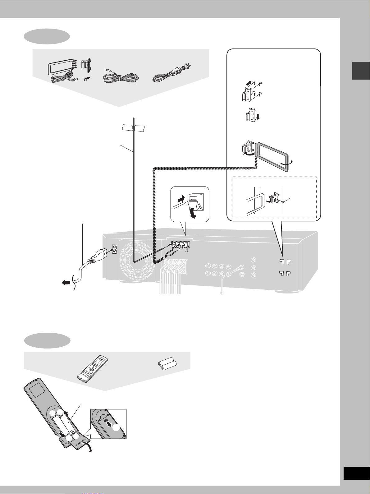
STEP4 Antennas and AC power supply cord
5
AM loop antenna set AC power supply cordFM indoor antenna
Plug in the AC power supply cord after
making all connections.
FM indoor antenna
Fix the other end of the antenna
where reception is best.
AC power supply cord
(included)
Adhesive tape
2
1
AM loop antenna
Keep loose antenna cord away from
other wires and cords.
1
AM loop antenna
holder (included)
2
3
To attach to a wall or other surface
Turn the antenna to the
angle of best reception
and least interference
Screw
(included)
Simple setup
AC IN~
To household
AC outlet
Conserving power
The unit consumes power (approx. 0.5 W) even when it is turned
off with [Í]. To save power when the unit is not to be used for a
long time, unplug it from the household AC outlet.
STEP
Remote control
The remote control
Batteries
R6/LR6, AA, UM-3
+
3
-
3
-
+
≥Insert so the poles (i and
j) match those in the
1
remote control.
≥Do not use rechargeable
type batteries.
2
FM ANT
75
AM ANT
LOOP
GND
EXT
LOOP ANT
HOLDER
Remember to reset the radio stations and any other memory items
before using the unit again.
Information you enter into the unit’s memory remains intact for up
to 1 week after the AC power supply cord is disconnected.
Do not;
≥mix old and new batteries.
≥use different types at the same time.
≥heat or expose to flame.
≥take apart or short circuit.
≥attempt to recharge alkaline or manganese batteries.
≥use batteries if the covering has been peeled off.
Mishandling of batteries can cause electrolyte leakage which
can damage items the fluid contacts and may cause a fire.
Remove if the remote control is not going to be used for a long
period of time. Store in a cool, dark place.
∫ Use
Aim at the sensor, avoiding obstacles, at a maximum range of
7 m (23 feet) directly in front of the unit.
RQT7089
9
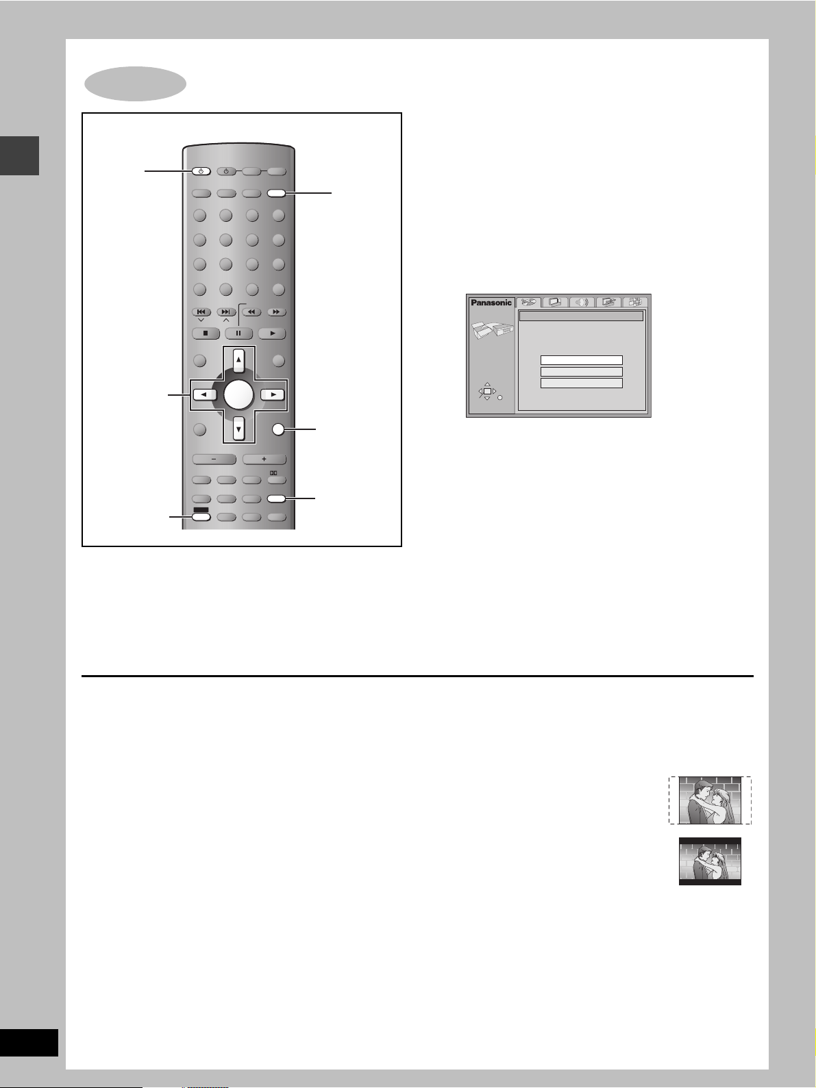
STEP6 QUICK SETUP
Preparation
Turn on the television and select the appropriate video input on the
television to suit the connections for the unit.
AV SYSTEM
1
Simple setup
TV/VIDEO
DISC
PAGE
GROUP
DISC
MANAGER
REPEAT
PLAY MODE
TOP MENU
DIRECT
NAVIGATOR
4–7
DISPLAY
s
TV VOL
SUBWOOFER
LEVEL
TIMER
SHIFT
3, 7
TV VCR
AUX
TUNER/BAND DVD/CD
123
DISC 1 DISC 2
456
DISC 4 DISC 5
7809
FL DISPLAY
CANCEL
SKIP
SLOW/SEARCH
CH
ENTER
VOLUME
C.FOCUS
S.POSITION
SFC
S.SRND
POSITION
ZOOM
MEMORY
AUDIO
TEST
QUICK
CH SELECT
REPLAY
DISC 3
S10/ENTER
MENU
PLAY LIST
RETURN
TV VOL
MIX 2CH
PL
SETUP
MUTING
SUBTITLE
r
2
RETURN
3, 7
1 Press [Í] to turn on the unit.
2 Press [DVD/CD] to select “DVD/CD”
as the source.
3 Press [SHIFT]i[SETUP] to show the
QUICK SETUP screen.
SETUP
SELECT
ENTER RETURN
QUICK SETUP
Select the menu language.
English
Français
Español
4 Press [3, 4] to select the menu
language and press [ENTER].
5 Press [3, 4] to select “Yes” to
continue and press [ENTER].
6 Press [3, 4] to select the item and
The QUICK SETUP screen appears when you press [SHIFT]i
[SETUP] the first time after purchase and assists you to make
necessary settings. You can access this screen again later if you
need to (➡ page 32, Others —QUICK SETUP).
press [ENTER].
≥Audio Language (➡ page 32)
≥Subtitle Language (➡ page 32)
≥TV Type (➡ below)
≥TV Aspect (➡ below)
7 Press [ENTER] and then [SHIFT]i
[SETUP] to end the settings.
RQT7089
10
To return to the previous screen
Press [RETURN].
∫ TV Type
Select to suit the type of television.
≥Standard (Direct View TV) (factory preset)
≥CRT Projector
≥LCD TV/Projector
≥Projection TV
≥Plasma TV
∫ TV Aspect
Select “4:3” (regular) or “16:9” (widescreen) to suit your
television.
If you have a regular 4:3 television, you can also select how video
on some discs is shown (➡ page 32, Video—TV Aspect).
≥4:3 Pan&Scan (factory preset)
Widescreen software is expanded to fill the
screen of a 4:3 aspect television (unless
prohibited by the producer of the disc).
≥4:3 Letterbox
Widescreen software is shown in the
letterbox style on a 4:3 aspect television.
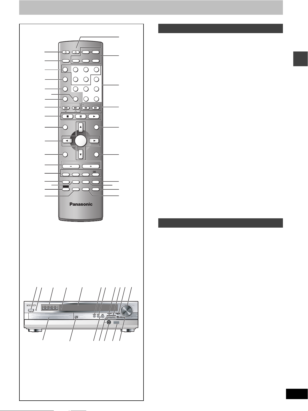
Control reference guide
AV SYSTEM
1
2
3
4
5
7
8
9
:
;
<
=
>
?
A
B
6
@
TV/VIDEO
DISC
PAGE
GROUP
DISC
MANAGER
REPEAT
PLAY MODE
SKIP
TOP MENU
DIRECT
NAVIGATOR
DISPLAY
TV VOL
s
SUBWOOFER
LEVEL
TIMER
SHIFT
TV VCR
TUNER/BAND DVD/CD
AUX
123
DISC 1 DISC 2
456
DISC 4 DISC 5
7809
FL DISPLAY
CANCEL
CH
S.POSITION
SFC
POSITION
MEMORY
TEST
CH SELECT
ENTER
VOLUME
C.FOCUS
S10/ENTER
SLOW/SEARCH
S.SRND
ZOOM
AUDIO
QUICK
REPLAY
PLAY LIST
TV VOL
MIX 2CH
MUTING
SUBTITLE
DISC 3
MENU
RETURN
r
PL
SETUP
J
C
D
E
F
G
H
I
K
L
Remote control
1 Standby/on switch [Í]. . . . . . . . . . . . . . . . . . . . . . . . . . . . . . 10
2 TV/VIDEO button [TV/VIDEO]. . . . . . . . . . . . . . . . . . . . . . . . . 30
3 Disc select button [DISC], Disc buttons [DISC1]–[DISC5] . . 12
4 Group, Page button [GROUP, PAGE]. . . . . . . . . . . . . . . . 14, 15
5 Disc manager button [DISC MANAGER]. . . . . . . . . . . . . . . . 13
6 Cancel, FL display button [CANCEL, FL DISPLAY] . . . . 17, 29
Play mode, Repeat button [PLAY MODE, REPEAT]
7
8 Skip, Preset channel, TV channel button
[: 9, SKIP, X CH W] . . . . . . . . . . . . . . . . . . . . . 14, 25, 30
9 Basic operation buttons. . . . . . . . . . . . . . . . . . . . . . . . . . . . . 12
: Top menu, Direct navigator button
[TOP MENU, DIRECT NAVIGATOR] . . . . . . . . . . . . . . . . . 12, 19
; Cursor buttons [3, 4, 2, 1], Enter button [ENTER] . . . . . 10
Display, TV volume down button [DISPLAY, TV VOLs]
<
= Volume buttons [s, r, VOLUME]. . . . . . . . . . . . . . . . . . . . . . 12
> Sound field, sound quality buttons. . . . . . . . . . . . . . . . . 26–28
Timer button [TIMER]
?
. . . . . . . . . . . . . . . . . . . . . . . . . . . . . . . 29
@ Position memory button [POSITION MEMORY]. . . . . . . . . . 13
A Shift button [SHIFT]
To use functions labeled in orange:
While pressing [SHIFT], press the corresponding button.
B Channel select, Test button [CH SELECT, TEST] . . . . . . . . 26
C AV system standby/on button [Í, AV SYSTEM] . . . . . . . . . 30
D Source select buttons
Face towards this unit to change the source.
Press [TV] or [VCR] first to operate a Panasonic television or
video cassette recorder (➡ pages 30, 31).
E Numbered buttons [1–9, 0, S10/ENTER] . . . . . . . . . . . . . . . 14
F Slow/search button [6, 5 SLOW/SEARCH] . . . . . . . . . 14
G Menu, Play list button [MENU, PLAY LIST]. . . . . . . . . . . 12, 19
H Return, TV volume up button [RETURN, TV VOLr] . . . 10, 30
I Muting, Setup button [MUTING, SETUP] . . . . . . . . . . . . 10, 29
J Audio, Zoom button [AUDIO, ZOOM] . . . . . . . . . . . . . . . 16, 18
K Subtitle button [SUBTITLE] . . . . . . . . . . . . . . . . . . . . . . . . . . 16
L Quick replay button [QUICK REPLAY] . . . . . . . . . . . . . . . . . 14
. . . . . 15, 17
. . 22, 30
Getting started
1
M
W
N
O
X
P
Y
Main unit
1 Standby/on switch [POWER Í/I]. . . . . . . . . . . . . . . . . . . . . . 10
Press to switch the unit from on to standby mode or vice versa.
In standby mode, the unit is still consuming a small amount of power.
M AC supply indicator [AC IN]
This indicator lights when the unit is connected to the AC mains
supply.
N Disc select buttons/indicators [DISC 1–5] . . . . . . . . . . . . . . 12
O Wake timer indicator [WAKE] . . . . . . . . . . . . . . . . . . . . . . . . 29
P Display
Q Stop, Tune mode button [∫, TUNE MODE]. . . . . . . . . . . 12, 25
Q
TUNING
SELECTOR
Z
[
R
T
SUBWOOFER LEVEL
SFC
DISCSKIP
\
]
V
U
S
R Pause, FM mode button [;, FM MODE] . . . . . . . . . . . . . 12, 25
S Progressive out button [PROGRESSIVE OUT] . . . . . . . . . . 12
T Sound field control button [SFC] . . . . . . . . . . . . . . . . . . . . . 27
U Subwoofer level button [SUBWOOFER LEVEL] . . . . . . . . . 28
V Volume control [VOLUME, DOWN, UP]. . . . . . . . . . . . . . . . . 12
W Disc tray. . . . . . . . . . . . . . . . . . . . . . . . . . . . . . . . . . . . . . . . . . 12
X Open/close button [<, OPEN/CLOSE] . . . . . . . . . . . . . . . . . 12
Y Play, Memory button [1, MEMORY] . . . . . . . . . . . . . . . . 12, 25
Z Skip/search, Tuning buttons
[:/6, 5/9, X TUNING W] . . . . . . . . . . . . . . . . . 14, 25
[ Headphone jack [PHONES] . . . . . . . . . . . . . . . . . . . . . . . . . . 29
\ Remote control signal sensor
] Source select button [SELECTOR] . . . . . . . . . . . . . . . . . . . . 25
RQT7089
11
Disc operations
RQT7089
12
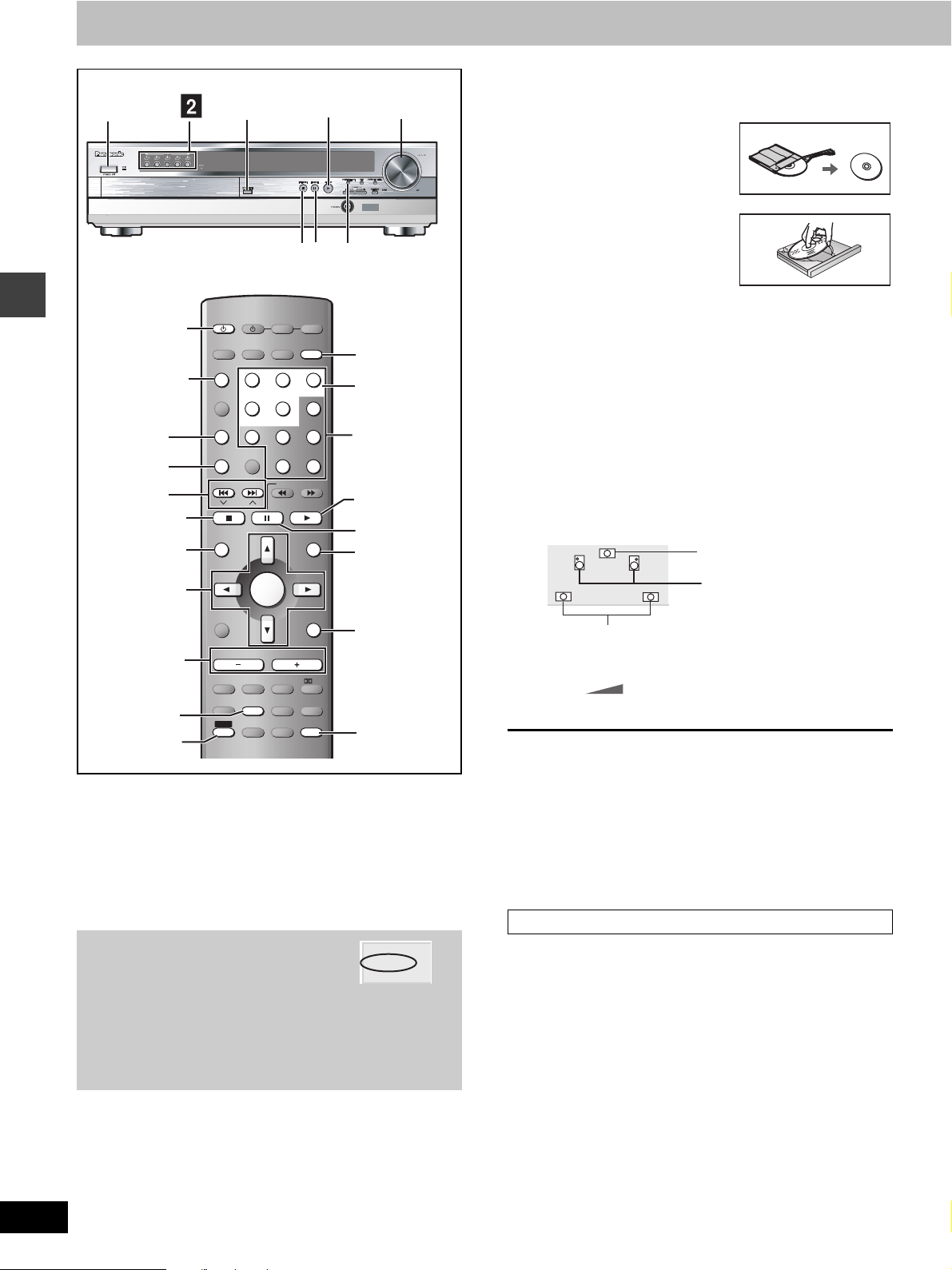
Discs—Basic play
TUNING
∫;
TV VCR
DISC 3
S10/ENTER
%
SELECTOR
PROGRESSIVE OUT
POWER Í/I
DISC
MANAGER
Í
@
#, $
AV SYSTEM
AUX
TV/VIDEO
DISC
123
DISC 1 DISC 2
PAGE
GROUP
456
DISC 4 DISC 5
DISC
MANAGER
7809
FL DISPLAY
REPEAT
PLAY MODE
CANCEL
TUNER/BAND DVD/CD
REPEAT
SKIP
: 9
SKIP
SLOW/SEARCH
CH
∫
C.FOCUS
S.SRND
ZOOM
AUDIO
QUICK
REPLAY
MENU
PLAY LIST
RETURN
TV VOL
MIX 2CH
PL
SETUP
MUTING
SUBTITLE
r
TOP MENU
342 1
ENTER
^
POSITION
MEMORY
TOP MENU
DIRECT
NAVIGATOR
DISPLAY
s
TV VOL
SUBWOOFER
LEVEL
TIMER
SHIFT
ENTER
VOLUME
S.POSITION
SFC
POSITION
MEMORY
TEST
CH SELECT
SHIFT
[RAM] [DVD-A] [DVD-V] [VCD] [CD] [WMA] [MP3] [JPEG]
Preparation
≥Press [Í] to turn on the unit.
≥Turn on the television and select the appropriate video input on the
television to suit the connections for the unit.
SUBWOOFER LEVEL
SFC
DISCSKIP
!
@
Numbered
buttons
%
;
MENU
RETURN
SUBTITLE
^
[1] Press [DVD/CD] to select “DVD/CD” as
the source.
To enjoy progressive video
Press [PROGRESSIVE OUT].
The television will be disrupted for a
moment but this is normal.
≥Output from this unit is interlace if you have connected to the
television through the VIDEO OUT or S-VIDEO OUT or
playing PAL discs, even if “PROGRESSIVE” is on the display.
≥When progressive output is on, closed captions will not be
displayed.
PROGRESSIVE
[2] Press [DISC] and then ([DISC 1]–
[DISC 5]).
The indicator on the main unit lights.
Play starts if a disc is in the tray.
Main unit: Press [DISC 1]–[DISC 5].
[3] Press [<] to open the disc tray and
place the disc.
≥Remove TYPE 2 and 4 discs
from their cartridges before
use. [RAM]
≥Label-up (With double-sided
discs, load so the label for the
side you want to play is facing
up.)
[4] Press [<] to close
the disc tray.
If the disc contains both audio data (WMA and MP3) and
JPEG, check “Mixed Disc—Audio & Stills” setting in the
SETUP menu (➡ page 32). Select “Stills (JPEG)” or “Audio
(MP3/WMA)”.
[5] Press [1] (play).
Play begins.
[WMA] [MP3] [CD] (CD text only)
Group and track names are displayed on the television.
≥Press [SUBTITLE] to turn the display on or off.
≥You can also use the navigation menus to control play
(➡ page 20).
Center speaker
Front speakers
Surround speakers
[6] Adjust the volume.
– – dB
(Minimum) (Maximum)
∫ To pause play
Press [;] during play.
Press [1] (play) to restart play.
∫ To stop play
Press [∫] (➡ page 13, Resume function).
[Note]
≥If “$” appears on the television
The operation is prohibited by the unit or disc.
≥It may take some time for play to start but this is normal.
When a menu appears on the television
[DVD-A] [DVD-V] [VCD]
Press the numbered buttons to select an
item.
To select a 2-digit number
Example: To select item 23, press [S10] ➡ [2] ➡ [3].
≥When playing DVDs, you can also use [3, 4, 2, 1] to select
items. Press [ENTER] to confirm your selection.
To return to the menu screen
[DVD-A] [DVD-V] [TOP MENU]: Shows the first menu screen.
[DVD-V] [MENU]: Shows the menu screen.
[VCD] [RETURN]: Shows the menu screen.
[Note]
The disc continues to rotate while the menu is displayed even after
you finish playing an item. Press [∫] when you finish to preserve the
unit’s motor and your television screen.
0 dB
 Loading...