

Page 1

Home Theater Audio System
Operating Instructions
Model No. SC-HT400
Dear customer
Thank you for purchasing this product.
Before connecting, operating or adjusting this product, please read
these instructions completely.
Please keep this manual for future reference.
RQT6361-P
P
Page 2
2
RQT6361
IMPORTANT SAFETY INSTRUCTIONS
Safety
1. Power source—Connect the unit to a power source of the type
described in these instructions or as marked on the unit.
2. Polarization—The unit is equipped with a polarized power plug
where one blade is wider than the other. This safety feature
ensures that the plug fits into your household AC outlet only one
way. If the plug doesn’t fit one way, try reversing it. If the plug
still doesn’t fit, contact an electrician to replace the obsolete
outlet. Do not attempt to defeat the safety purpose of the plug.
3. Power cord protection—Route the AC power supply cord so
that it will not be walked on or pinched by items placed on or
against it. Never take hold of the plug or cord with wet hands.
Always grasp the plug body firmly when connecting and
disconnecting it.
4. Overloading—When connecting the AC power supply cord, be
careful not to overload the household AC outlet, extension cord,
or outlet from any other device as this can result in fire or electric
shock.
5. Nonuse periods—Turn the unit off when it is not in use. Unplug
the unit from the household AC outlet if it is not to be used for a
long time. Unplug the unit during lightning storms.
6. Attachments and accessories—Use only the attachments and
accessories recommended in these operating instructions.
Read these operating instructions carefully before using the unit. Follow the safety instructions on the unit and the safety precautions listed
below. Keep these operating instructions handy for future reference.
Installation
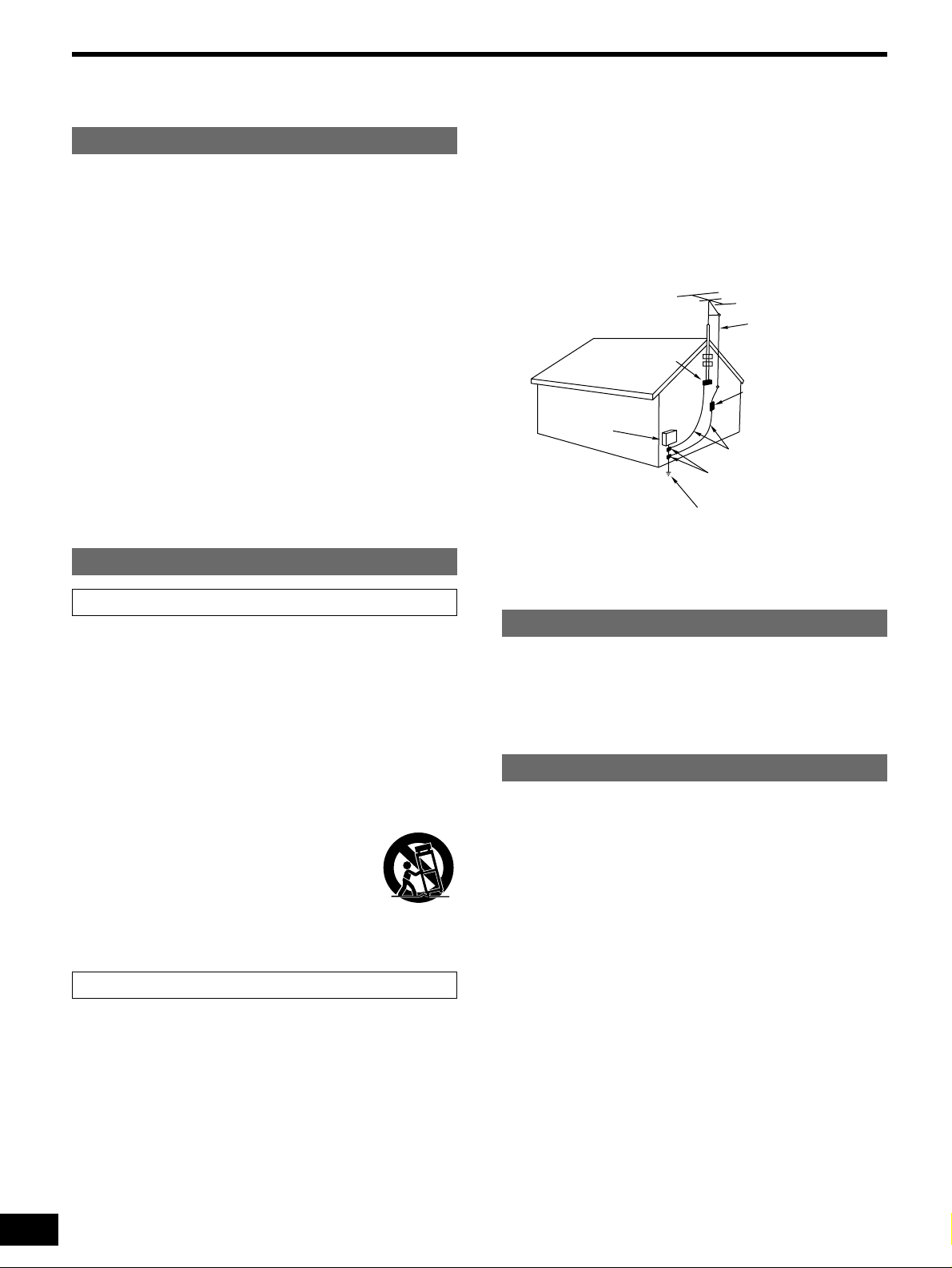
4. Outdoor antenna grounding—If you connect an outdoor
antenna, ground the antenna system to protect against voltage
surges and built-up static charges. Section 810 of the National
Electrical Code, ANSI/NFPA No. 70-1990, provides information
about grounding of the mast and supporting structure, grounding
of the lead-in wire to an antenna discharge unit, size of
grounding conductors, location of antenna-discharge unit,
connection to grounding electrodes, and requirements for the
grounding electrode. Refer to this diagram.
Environment
ELECTRIC
SERVICE
EQUIPMENT
GROUND
CLAMP
ANTENNA
LEAD IN
WIRE
ANTENNA
DISCHARGE UNIT
(NEC SECTION 810-20)
GROUNDING CONDUCTORS
(NEC SECTION 810-21)
GROUND CLAMPS
POWER SERVICE GROUNDING
ELECTRODE SYSTEM
(NEC ART 250, PART H)
NEC—NATIONAL ELECTRICAL CODE
1. Water and moisture—Do not use the unit near water, such as
near a bathtub or swimming pool. Avoid damp basements.
2. Heat—Situate the unit away from heat sources, such as
radiators.
Do not situate where temperatures fall below 5°C (41°F) or rise
above 35°C (95°F).
3. Power lines—Take care when setting up an outdoor antenna
that it is not near overhead power lines, electric lights, or
electrical circuits, and that there is no danger of the antenna
falling on power lines, electric lights, or electrical circuits. When
installing an outdoor antenna, take extreme care not to touch
such power lines or circuits, as contact with them can be fatal.
Placement
1. Ventilation—Situate the unit so that it receives proper
ventilation. Do not install in a confined space such as a
bookcase or cabinet. Allow at least 10 cm (4 inches) clearance
from the rear of the unit. To prevent the risk of electric shock or
fire due to overheating ensure curtains and other materials do
not obstruct the unit’s ventilation.
2. Foreign material—Ensure objects and liquids do not get into
the unit. Avoid exposing the unit to excessive smoke, dust,
mechanical vibration, and shock.
3. Magnetism—Situate the unit away from equipment and devices
that generate strong magnetic fields.
4. Stacking—Do not place heavy objects on top of this unit.
5. Surface—Place the unit on a flat, level surface.
6. Carts and stands—Use the unit only with carts
and stands recommended by the manufacturer.
Move carts with care. Sudden stops, excessive
force, and uneven surfaces can cause carts to
overturn.
7. Wall and ceiling mounting—Do not mount the unit on walls or
ceilings unless specified in the instructions.
Maintenance
(See page 16 for details.)
Unplug the unit from the household AC outlet before cleaning.
Clean with a damp cloth.
Do not use abrasive pads, scouring powders, or solvents.
Service
1. Damage requiring service—The unit should be serviced by
qualified service personnel if:
(a) The AC power supply cord or the plug has been damaged; or
(b) Objects or liquids have gotten into the unit; or
(c) The unit has been exposed to rain; or
(d) The unit does not operate normally or exhibits a marked
change in performance; or
(e) The unit has been dropped or the cabinet damaged.
2. Servicing—Do not attempt to service the unit beyond that
described in these operating instructions. Refer all other
servicing to authorized servicing personnel.
3. Replacement parts—When parts need replacing ensure the
servicer uses parts specified by the manufacturer or parts that
have the same characteristics as the original parts.
Unauthorized substitutes may result in fire, electric shock, or
other hazards.
4. Safety check—After repairs or service, ask the servicer to
perform safety checks to confirm that the unit is in proper
working condition.
Page 3
3
RQT6361
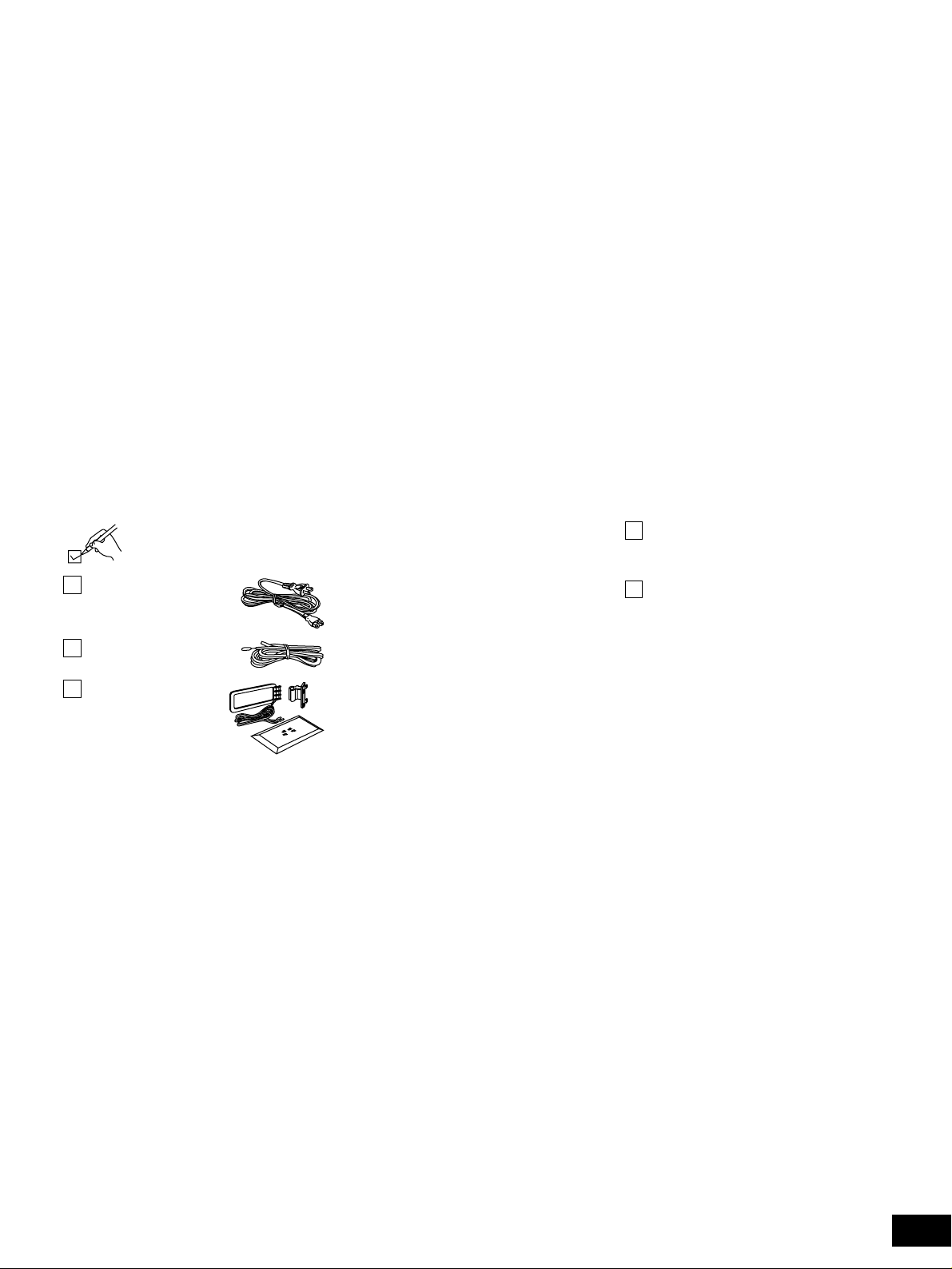
Please check and identify
the supplied accessories.
1 AC power supply cord
(RJA0065-A)
1 AM loop antenna set
(N1DAEYA00006)
(AM loop antenna,
antenna holder,
stand)
Use the numbers indicated in parentheses when asking for
replacement parts.
1 FM indoor antenna
(RSA0006-L)
2 Batteries
1 Remote control
(EUR7702KE0)
Page 4
4
RQT6361
Speaker connections
Step
1
2 3 4
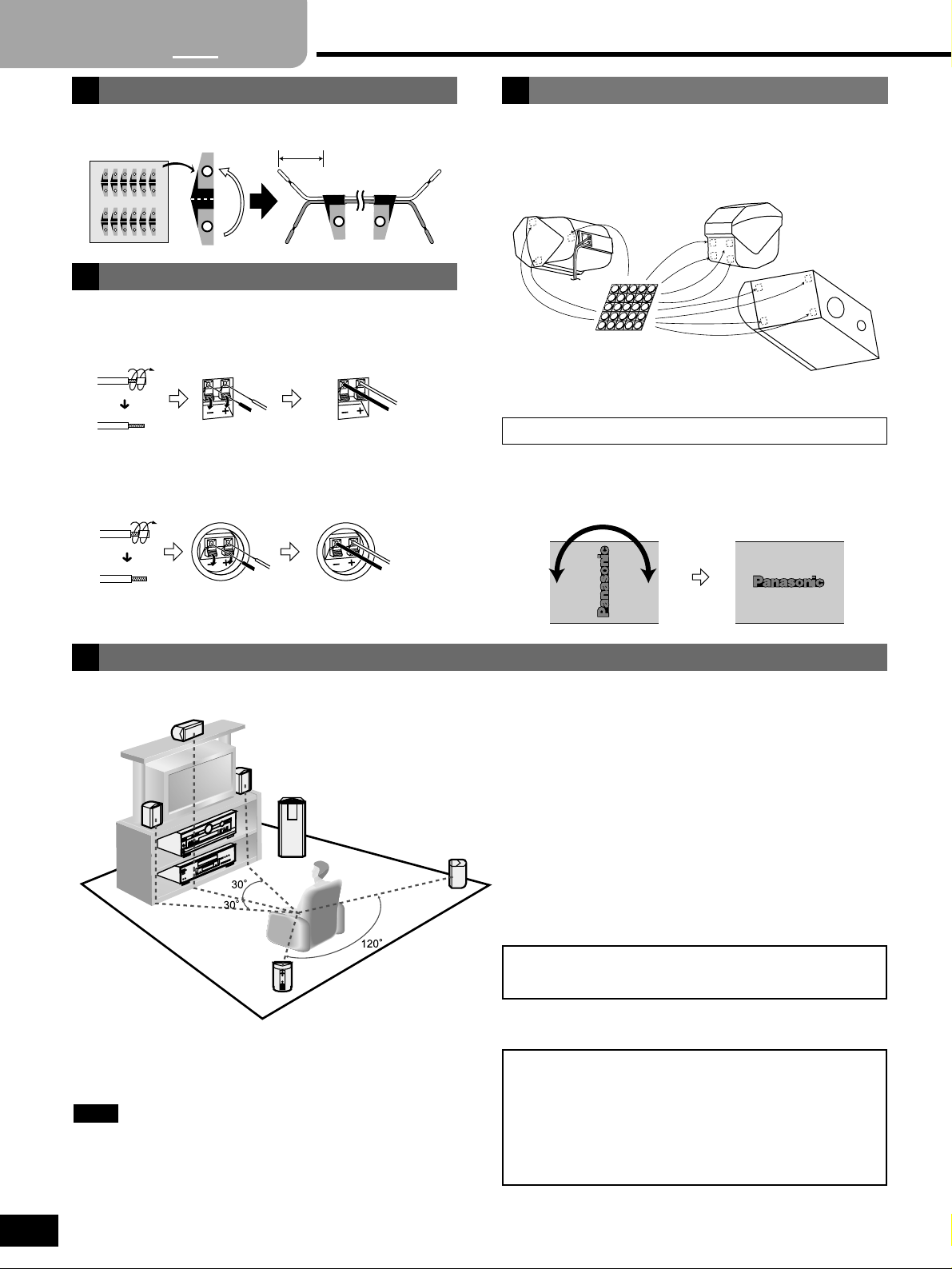
Attach the stickers to the speaker cords
Placement of speakers
Front speakers (1 left 2 right)
Place on the left and right of the TV at seated ear height.
Center speaker (3)
Place underneath or above the center of the TV.
Surround speakers (4 left 5 right)
Place slightly behind the seating area, about one meter (3 feet)
higher than ear level.
Subwoofer (6)
The subwoofer can be placed in any position as long as it is at a
reasonable distance from the TV.
The front, center, and surround speakers should be placed at
approximately the same distance from the seating area. The
angles in the diagram are approximate.
About 10 cm (4")
The 6 speaker cords are all the same.
Connecting speakers and speaker cords
Rear panel of small speakers (The 5 small speakers are the same.)
Rear panel of large speaker
Connect the cable with sticker 6 attached to the large speaker:
subwoofer.
Set-up the speakers so the numbers on the attached stickers correspond to the positions shown in the diagram.
Attach the rubber feet to the speaker
Small speaker
Standing
Lying down
Large
speaker
If irregular coloring occurs on your television
These speakers are designed to be used close to a television, but
the picture may be affected with some televisions and set-up
combinations.
If this occur, turn the television off for about 30 minutes.
The television’s demagnetizing function should correct the
problem. If it persists, move the speakers further away from the
television.
Moving the brand plate
You can turn the brand plate if you want to set up the small
speakers laying on their sides.
Ensure the plate doesn’t get caught on the net when you turn it.
The speaker nets cannot be removed.
1
F
RO
N
T
L
1
1
FRONT L
FRONT L
1
1
FRONT L
FRONT L
2
2
FRONT R
FRONT R
3
3
CENTER
CENTER
4
4
SURROUND L
SURROUND L
5
5
SURROUND R
SURROUND R
6
6
SUBWOOFER
SUBWOOFER
1
1
FRONT L
FRONT L
2
2
FRONT R
FRONT R
3
3
CENTER
CENTER
4
4
SURROUND L
SURROUND L
5
5
SURROUND R
SURROUND R
6
6
SUBWOOFER
SUBWOOFER
1
F
R
O
N
T
L
Connect the cables with stickers 1 to 5 attached to the small
speakers: 2 x front, 2 x surround, and 1 x center.
1
2
3
4
5
6
One sheet of 25 rubber feet is included. Use 3 or 4 feet per
speaker.
Positioning for best effect
How you set up your speakers can affect the bass and the sound
field.
¡Place speakers on flat secure bases.
¡Placing speakers too close to floors, walls, and corners can result
in excessive bass. Cover walls and windows with thick curtain.
¡Keep your speakers at least 10 mm (13/32") away from the
system for proper ventilation.
Note
1
2
3
4
Attach these rubber feet to prevent vibration causing the speakers
to move or fall over. The five small speakers can be set-up either
standing or lying down.
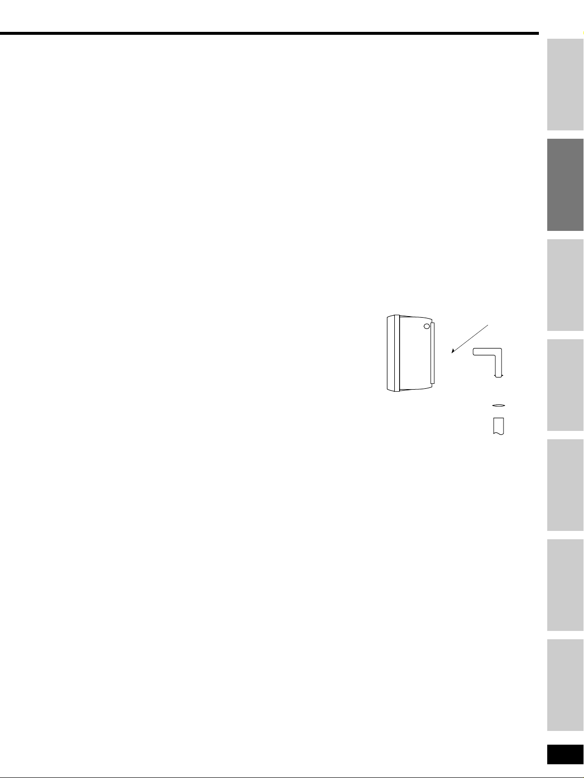
See page 5 if you would prefer to hang the speakers on a wall or
use speaker stands.
Connect the red cord to the red terminal (+) and the black cord to
the black terminal (–).
Page 5
5
RQT6361
Step 1
Step 2
Step 3
Before use
Step 4
Others
Reference
Page 6
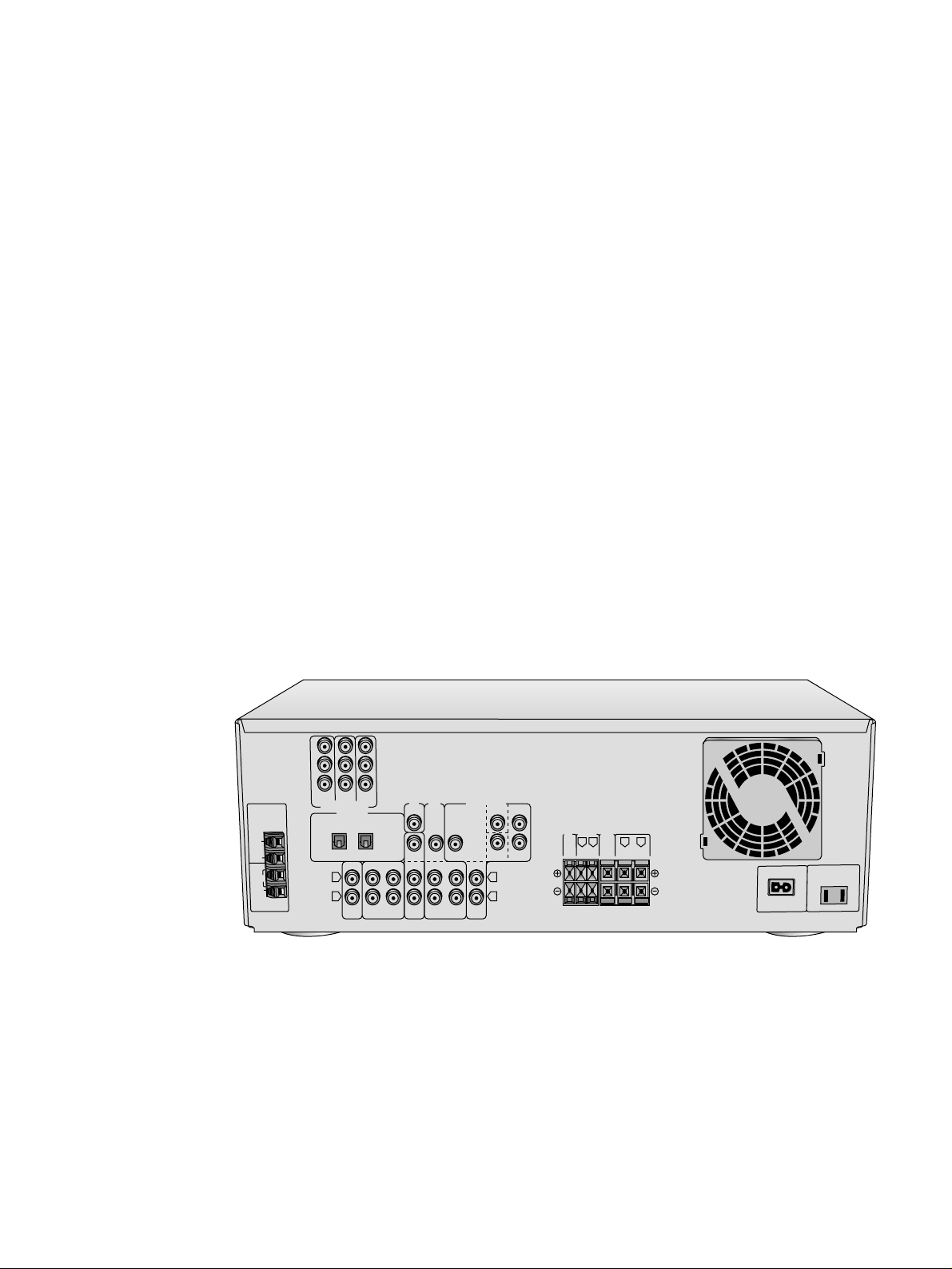
L
R
L
R
FM
ANT
AM
ANT
GND
LOOP
EXT
75Ω
AC IN
∼
AC
OUTLET
R L
R L
Y
P
B
P
R
COMPONENT VIDEO
DIGITAL IN
TV VCR DVD/DVD 6CH
CD TAPE TV
FRONT
TV
Page 7
L
R
L
R
FM
ANT
AM
ANT
GND
LOOP
EXT
75Ω
AC IN
∼
AC
O
U
TLET
R L
R L
Y
P
B
P
R
COMPONENT VIDEO
DIGITAL IN
TV VCR DVD/DVD 6CH
CD TAPE TV
FRONT
TV
MONITOR OUT
OPTICAL1
(TV)
OPTICAL2
(DVD)
REC
(OUT)
PLAY
(IN)
OUT IN
COAXIAL
DVDINTV
IN
MONITOR
OUT
MONITOR
OUT
CENTER
SURROUND
IN
IN
L
R
IN
SUBWOOFER
IN
IN
IN
S-VIDEO
TV TV VCR DVD
SPEAKERS
HAUT-PARLEURS
SURROUND
FRONT
CENTERSUB-
WOOFER
6-8Ω/EACH SPEAKER
6-8Ω/CHAQUE
6 5 4 3 2 1
7
RQT6361
L
R
L
R
FM
ANT
AM
ANT
GND
LOOP
EXT
75Ω
R L
R L
Y
P
B
P
R
COMPONENT VIDEO
DIGITAL IN
TV VCR DVD/DVD 6CH
CD TAPE TV
FRONT
TV
MONITOR OUT
OPTICAL1
(TV)
OPTICAL2
(DVD)
REC
(OUT)
PLAY
(IN)
OUT IN
COAXIAL
DVDINTV
IN
MONITOR
OUT
MONITOR
OUT
CENTER
SURROUND
IN
IN
L
R
IN
SUBWOOFER
IN
IN
IN
S-VIDEO
TV TV VCR DVD
SPEAKERS
HAUT-PARLEURS
SURROUND
FRONT
CENTERSUB-
WOOFER
6-8Ω/EACH SPEAKER
6-8Ω/CHAQUE
6 5 4 3 2 1
AC IN
∼
AC
OUTLET
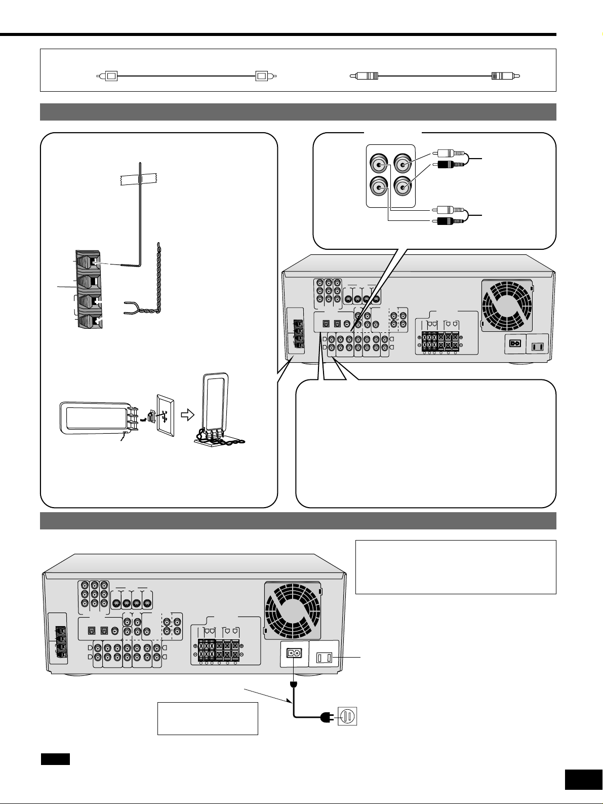
Optical fiber cable Coaxial cable
CD, Tape deck and antennas
CAUTION:
TO PREVENT ELECTRIC SHOCK
MATCH WIDE BLADE OF PLUG TO
WIDE SLOT, FULLY INSERT.
The included AC power supply cord is for use with
this unit only. Do not use it with other equipment.
Note
Conserving power
The unit consumes 1 W even when it is turned off with [POWER, ^/l]. To
save power when the unit is not to be used for a long time, unplug it from the
household AC outlet.
If the unit is left unplugged for longer than a few weeks, all settings will revert
to the factory settings. Do the settings again if this occurs.
Household AC outlet
(AC 120 V/60 Hz)
Connect this cord after
all other cables and
cords are connected.
AC power supply cord
(included)
“SWITCHED” AC outlet
Power to the outlet is controlled by the power switch
of this unit. Audio equipment rated up to a maximum
of 80 W can be connected here. If equipment
exceeding this rating is connected, the outlet may be
rendered inoperable. Consult your dealer to replace
the fuse.
Connecting the AC power supply cord and other information
TAPE
REC
(OUT)
PLAY
(IN)
PLAY (OUT)
REC (IN)
If you have a graphic equalizer, connect it to the TAPE
terminals.
Tape deck
DIGITAL OUT
Fix the other end of the antenna
where reception is best.
Adhesive tape
FM indoor antenna (included)
AM loop antenna (included)
FM
ANT
AM
ANT
GND
LOOP
EXT
75Ω
Page 8
8
RQT6361
Step
1 2
3
4
Settings
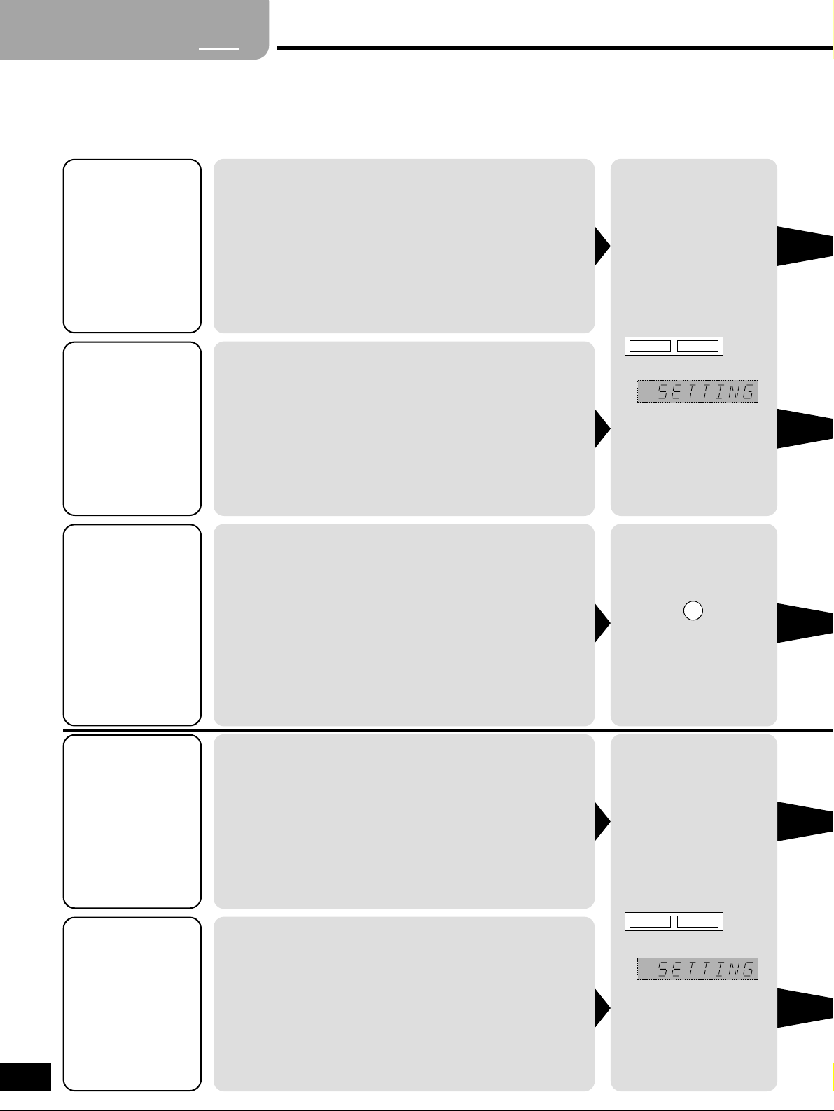
Change the settings to suit your equipment to the environment in which you are using it. Before making any changes, read the descriptions of
the settings, note the factory settings and ranges, and refer to the equipment’s instructions.
SFC MODE
wq
Press at the same
time to enter the
setting mode.
SIZE
Set the size to suit
your speakers
DISTANCE
Enter the distance of
the front, center and
surround speakers
from the seating
position
FILTER
Change the cut-off
for bass output from
the front speakers
Change the distance so that the sound from all the speakers (except for
the subwoofer) reaches you at the same time.
You can select distances between 3 and 30 feet at one-foot intervals.
The factory settings are: FRONT and CENTER: 10 FEET
SURROUND: 5 FEET
Adjusting
speaker output
level
Turn SPEAKERS
on.
Adjust the level of the other speakers based on the output of the front
speakers. (Adjust the volume of the front speakers with [VOLUME].)
C (center), SR (surround right), and SL (surround left) can be adjusted
between –10 dB and +10 dB, with 0 being the level of the front speakers.
Adjust center and surround output to the same apparent level of the front
speakers.
For SW (subwoofer), you can select “---” so there is no output, “MIN” for
minimum output, a level between 1 and 19, or “MAX” for maximum output.
Adjust subwoofer output so it is balanced with the front speakers.
Subwoofer output is easily influenced by the source. You can also change
its level while playing something to achieve a better effect (\page 13).
D-INPUT
Digital input
Change these settings to suit the connections you have made to the three
digital input terminals, COAX, OPT1 and OPT2, so that the correct source
is selected when you turn [INPUT SELECTOR].
The factory settings are: CD: COAX
DVD:OPT 2
TV: OPT 1
Press at the same
time to enter the
setting mode.
Change these settings only if you replace the included speakers.
LARGE:For speakers that can reproduce a full sound range, particularly
the bass range below 100 Hz.
SMALL:This is the factory setting and the optimum setting for the included
speakers. This setting is sufficient for most speakers if you are
using a subwoofer.
NONE: For speakers you haven’t connected (center or surround).
The factory settings are: FRONT, CENTER and SURROUND: SMALL
If you disconnect the subwoofer (SUB-WFR), select NO. Otherwise, leave
the setting as YES.
Change this setting only if you replace the included speakers. You can
change the cut-off for the bass output from the front speakers.
You can raise the cut-off from 100 Hz to either 150 Hz or 200 Hz.
The optimum setting for these speakers is 150 Hz.
SPEAKERS
wq
SFC MODE
Page 9
9
RQT6361
Step 1
Step 2
Step 3
Before use
Step 4
Others
Reference
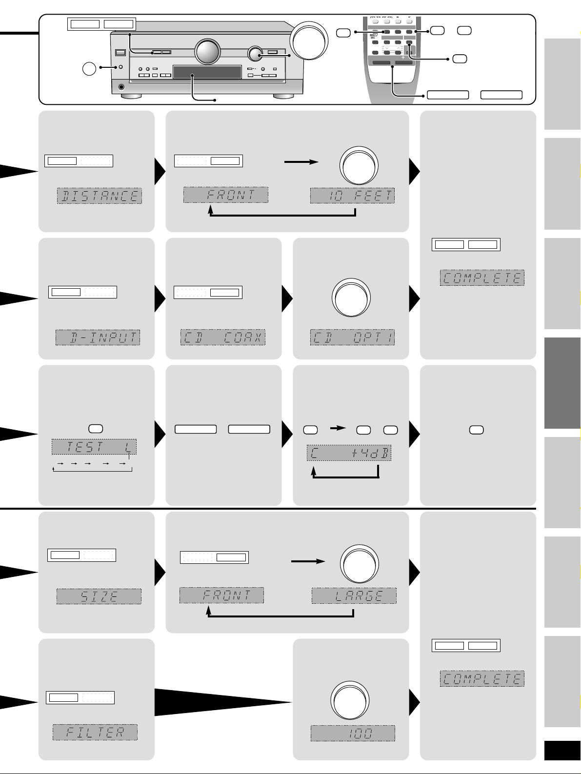
Select “SIZE”. Select the speaker. Change the
setting.
Press at the same
time to exit the
setting mode.
SFC MODE
w q
SFC MODE
wq
Select
“DISTANCE”.
Select “FILTER”.
Select the speaker. Change the
setting.
Change the
setting.
SFC MODE
w q
INPUT SELECTOR
Stop the test
signal.
Adjust the level.
Press [LEVEL] to select the
speaker channel, then press
[–] or [+].
VOLUME
+–
Adjust the main
volume.
TEST
Output the signal.
The speakers output a signal
in order for about two seconds
each.
LCRSRSLSW
SFC MODE
w q
SFC MODE
w q
INPUT SELECTOR
SFC MODE
w q
INPUT SELECTOR
Select “D-INPUT”. Select the input
position.
Change the
setting.
SFC MODE
w q
SFC MODE
w q
INPUT SELECTOR
wq
//
Repeat for each speaker channel.
Repeat for each speaker channel.
Speakers set as “NONE” or
“NO” are skipped.
LEVEL
Repeat for each
speaker channel.
Press at the same
time to exit the
setting mode.
SFC MODE
wq
POWER
SPEAKERS
SPEAKERS
PHONES
8
SFC MODE
- BAND
- HELP
– FM MODE
– RESET
MEMORY
DSP
SOUND MODE
TUNING
PRESET
2wq1
INPUT SELECTOR
VOLUME
SFC MODE
DOWN UP
DOLBY
PRO LOGIC 2
INPUT SELECTOR
BASS/TREBLE
BALANCE L R
DIGITAL INPUT
DVD 6CH INPUTSUBWOOFERTAPE MONITOR
34
LEVEL
EFFECT LEVEL
DISC
/
SOUND MODE
DECK 1/2
TV/VIDEO
VOLUME
+–
SFC
TEST
MUTING
CH
+–
+
–
TEST
–
VOLUME
+
DISPLAY
+–
TEST
Page 10
10
RQT6361
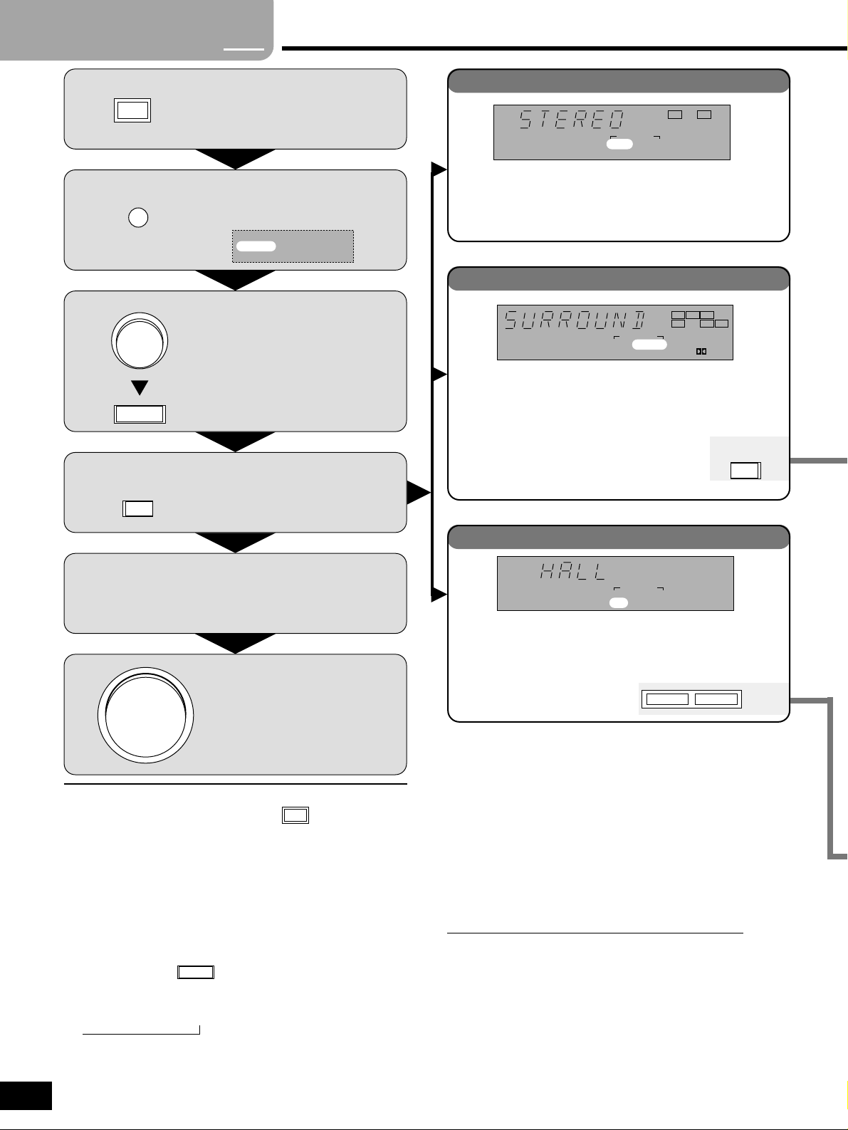
When you finish listening
Be sure to reduce the volume and press [ ] to switch the unit
to standby.
For your reference
In rare cases, the unit may have trouble recognizing the digital
signals on discs.
¡With the PCM signals on CDs, this may cause the beginning of a
track to be cut off. Engage the PCM FIX mode if this occurs.
¡With DTS, the signals may not be recognized at all. Engage the
DTS FIX mode if this occurs.
While the input source is selected and digital input is engaged:
Press and hold [ ].
The current mode is displayed. Press again to change the mode.
Each time you press the button:
AUTO / PCM FIX / DTS FIX
↑
When a FIX mode is on, the unit cannot process other signals. This
may cause noise to be output. Select “AUTO”if this occurs.
The selected mode is stored for each input source even if the unit is
turned off.
DIGITAL INPUT
POWER
8
Notes on using the Digital Signal Processor
The digital signal processor (DSP) in this unit can decode Dolby
Digital and DTS digital signals. It automatically determines the type
of signal, PCM, Dolby Digital, or DTS, and processes it accordingly.
¡This unit cannot process other digital signal formats, such as
PCM signals with sampling frequencies of 96 kHz and 192 kHz
and MPEG.
¡This unit cannot decode Dolby Digital RF (radio frequency)
signals from a laser disc player.
Use this mode to play digital or analog stereo sources or to play
surround sources through two speakers. When surround sources
are played in this mode, the sounds intended for the other
speaker channels are played through the front speakers.
Select this mode when you are playing a digital surround source
(Dolby Digital or DTS).
Also select this mode when playing analog or digital stereo
sources. The Dolby Pro Logic 2 processor works
not only on sources recorded with Dolby
Surround, but also on any stereo source. The
following modes are available when using Dolby
Pro Logic 2.
Enjoy an enhanced sound experience with greater presence and
spread by using these SFC (sound field control) modes with PCM
or analog stereo sources.
The SFC modes cannot be used if the input signal is Dolby
Digital or DTS.
Choose from the following modes.
Switch on.
POWER
8
Turn
SPEAKERS on.
SPEAKERS
Select input.
TUNER ↔ CD ↔ DVD
TAPE ↔ VCR ↔ TV
INPUT SELECTOR
DIGITAL INPUT
Select the DSP
sound mode.
Start play of the
source.
Adjust the
volume.
DOWN UP
VOLUME
1
2
3
4
5
6
DSP
SOUND MODE
SURROUND mode
STEREO mode
SFC modes
↔
↔
For CD, DVD, TV
Select digital or analog input.
Basic operations
Step
1 2 3
4
SPEAKERS
SOUND MODE
STEREO
LR
SPEAKERS
LCR
SL
SPEAKERS
SOUND MODE
SURROUND
SR LFE
DIGITAL
DOLBY
PRO LOGIC 2
SPEAKERS
SOUND MODE
SFC
wq
SFC MODE
Page 11
11
RQT6361
Step 1
Step 2
Step 3
Before use
Step 4
Others
Reference
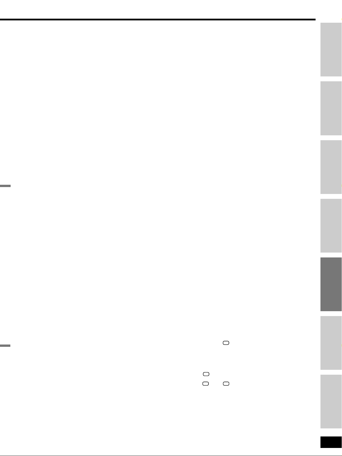
You can adjust the sound field by adjusting the level of the
speakers and the delay time of the surround speakers. These
adjustments can be made for each SFC mode.
To adjust the speaker level
11
Press [ ] to select the speaker channel.
Each time you press the button:
C / SR / SL / SW
↑
Speakers set as “NONE” or “NO” are skipped.
22
Press [ ] or [ ] to adjust the level.
C, SR, and SL: –10 dB to +10 dB
SW: --- (off) ,/ MIN ,/ 1 – 19 ,/ MAX
To adjust the delay time
11
Press [ ].
22
Press [ ] or [ ] to change the delay time.
Delay time can be set at 10-millisecond (ms) intervals between
10 and 100 ms.
The factory setting is 50 ms for each mode.
+
–
EFFECT
+
Page 12
12
RQT6361
POWER
SPEAKERS
SFC MODE
DOWN
PHONES
- HELP
– RESET
- BAND
– FM MODE
MEMORY
TUNING
PRESET
DSP
SOUND MODE
DOLBY
PRO LOGIC 2
8
2
wq
1
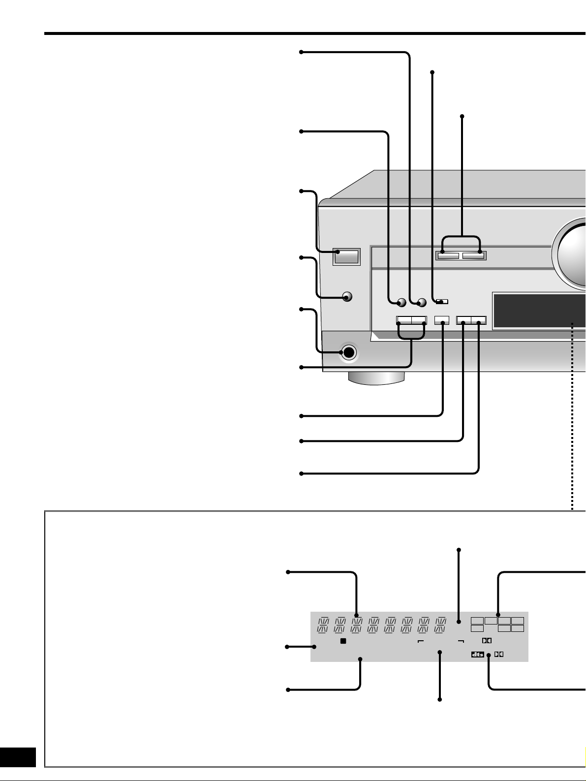
Standby/on button [POWER, 8]
Press to switch the unit from on to standby mode or vice versa.
In standby mode, the unit is still consuming a small amount of power.
Speaker on/off button [SPEAKERS]
Turning the speakers off automatically engages the STEREO mode
(when listening through headphones, for example).
Help/reset button [-HELP, –RESET]
Press if an error message appears. A message offering a possible
solution scrolls across the display.
To reinitiate the unit’s settings, press and hold until “RESET” appears.
Memory button [MEMORY]
For presetting radio stations.
SFC mode select buttons
[SFC MODE, w, q]
For selecting the SFC mode
Headphone jack [PHONES]
Plug type: 6.3 mm (1/4") stereo
Avoid listening for prolonged periods of time to prevent hearing
damage.
Tuning buttons [TUNING, 2, 1]
For tuning the radio and selecting preset stations.
Press and hold until the frequency starts scrolling to start automatic
tuning. Tuning stops when a station is found.
Tuning intervals: FM–0.2 MHz, AM–10 kHz
Preset channel button [PRESET]
Press to allow preset station selection with [TUNING, 2, 1].
Band select/FM mode select button
[-BAND, –FM MODE]
For switching between AM and FM.
If reception is poor in FM, press and hold until “MONO” appears to
switch to monaural mode.
DSP sound mode select button [DSP SOUND MODE]
For selecting “STEREO”, “SURROUND” or “SFC”
TUNED
STEREO
MONOSPEAKERS
kHz
MHz
PRO LOGIC 2
DIGITAL
SOUND MODE
STEREO SURROUND
SFC
LCRSLS
SR LFE
PCM
FIX
M
DSP sound mode indicators
[SOUND MODE, STEREO, SURROUND, SFC]
Show the current DSP sound mode.
Frequency unit indicators [kHz, MHz]
kHz: AM, MHz: FM
The display
Dolby Pro Logic 22mode select button
[DOLBY PRO LOGIC 22]
Use when “% PRO LOGIC 2” lights in the SURROUND mode.
Speaker indicator [SPEAKERS]
Lights when the speakers are on.
General display
Shows the input mode, radio frequency, and other general
information.
Radio indicators [TUNED, MONO, STEREO, ˜]
TUNED: A station is tuned.
MONO: You have switched to monaural mode with [-BAND, –FM
MODE] to improve reception.
STEREO: A stereo FM broadcast is tuned.
˜:Lights during presetting.
Control guide
Page 13
13
RQT6361
Step 1
Step 2
Step 3
Before use
Step 4
Others
Reference
UP
VOLUME
INPUT SELECTOR
DVD 6CH INPUTSUBWOOFERTAPE MONITOR
BASS/TREBLE
34
BALANCE L R
DIGITAL INPUT
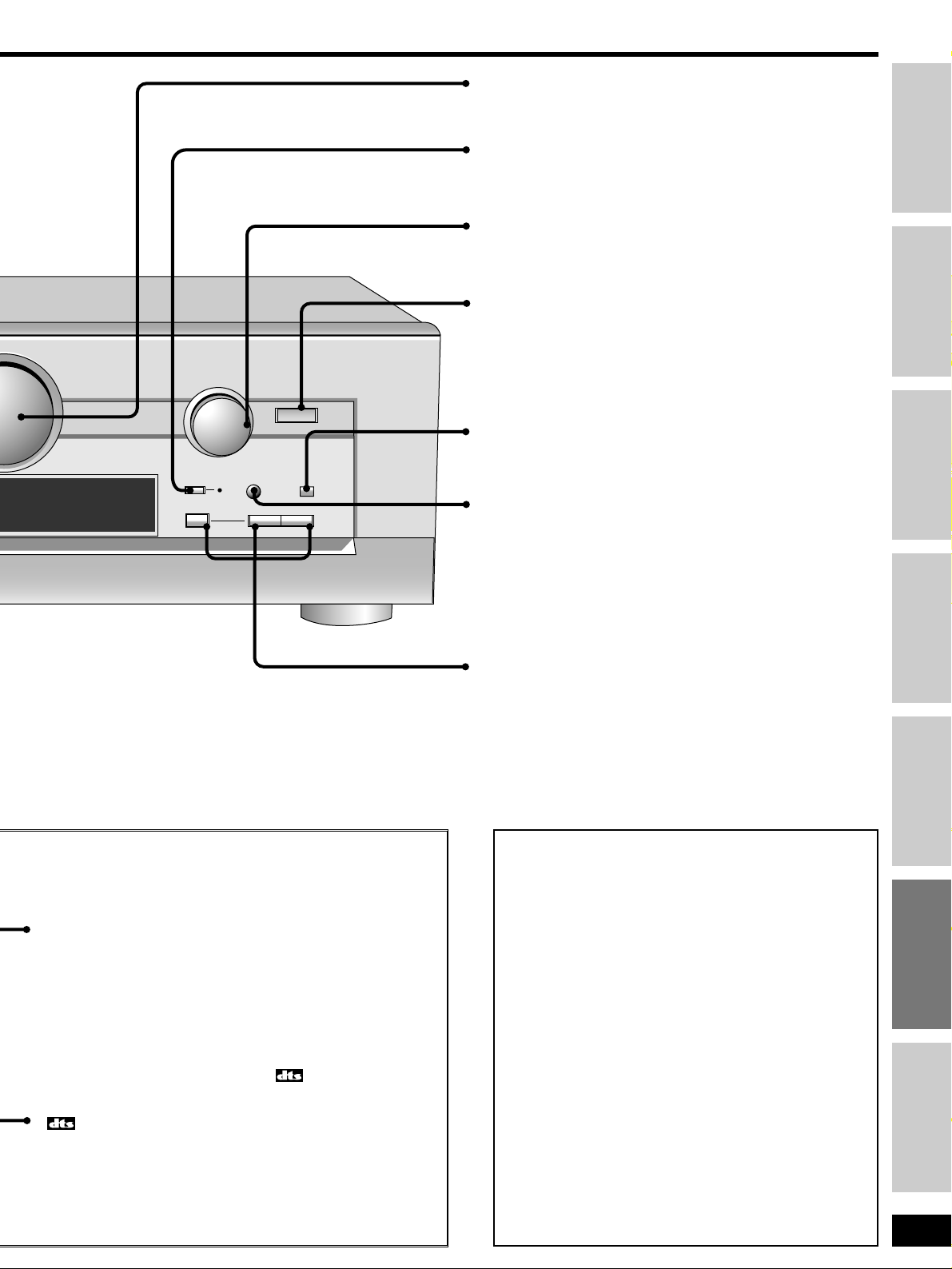
Input selector [INPUT SELECTOR]
Digital/analog input select button/indicator
[DIGITAL INPUT]
For switching between analog and digital input when you have
selected TV, CD, or DVD. The button lights when digital is selected.
Subwoofer level button [SUBWOOFER]
Adjust the level in 5 steps
SW MIN, SW 5, SW 10, SW 15, and SW MAX.
Select SW --- to stop output.
DVD 6ch/2ch input select button [DVD 6CH INPUT]
For switching between 6-channel and 2-channel DVD input.
Tape monitor button/indicator [TAPE MONITOR]
For monitoring sound when recording to a 3-head cassette deck.
Also used when you have connected a graphic equalizer to the TAPE
terminals.
Tone/balance adjust buttons
[BASS/TREBLE, BALANCE, –, +, L, R]
For adjusting the tone and balance.
First select BASS, TREBLE, or BALANCE, then press [–, L] or [+, R]
to adjust.
Program format indicators
[L, C, R, S, SL, SR, LFE]
Show the channels contained in the digital input signal. They do not
light when input is analog.
L: Front channel (left)
C: Center channel
R: Front channel (right)
S: If the surround channel is monaural.
SL: Surround channel (left)
SR: Surround channel (right)
LFE (Low Frequency Effect): Deep-bass effect.
Signal format indicators
[FIX, % PRO LOGIC 22, PCM, , % DIGITAL]
Light depending on the source you are playing.
% DIGITAL: Dolby Digital sources
: DTS sources
% PRO LOGIC 22: Analog sources in SURROUND mode
Digital sources with 2-channel signals in
SURROUND mode
FIX: PCM FIX or DTS FIX mode
PCM: PCM FIX mode
For your reference
¡When playing videotapes
The picture remains on the screen even if you select TAPE,
CD, or TUNER.
¡Once you have set a mode (DSP, digital/analog input, or
2-channel/6-channel input) for an input source
That mode is engaged whenever you reselect the input source.
¡When DVD 6CH input is on
Speaker settings are ineffective. Change the settings on the
DVD player if necessary.
¡When input is DIGITAL
The tape monitor cannot be used.
¡When using a graphic equalizer
Some distortion may occur, depending on the equalizer’s
settings.
¡To adjust the tone
The STEREO DSP mode must be on and input must be either
analog or PCM signals. You cannot adjust the tone while the
DSP is defeated or if DVD 6CH INPUT is selected.
¡When using the subwoofer
You cannot adjust subwoofer level while the DSP is defeated
or if DVD 6CH INPUT is selected.
Sound can be distorted if you raise the volume while subwoofer
level is high. Reduce subwoofer level if this occurs.
Volume control [VOLUME]
Page 14
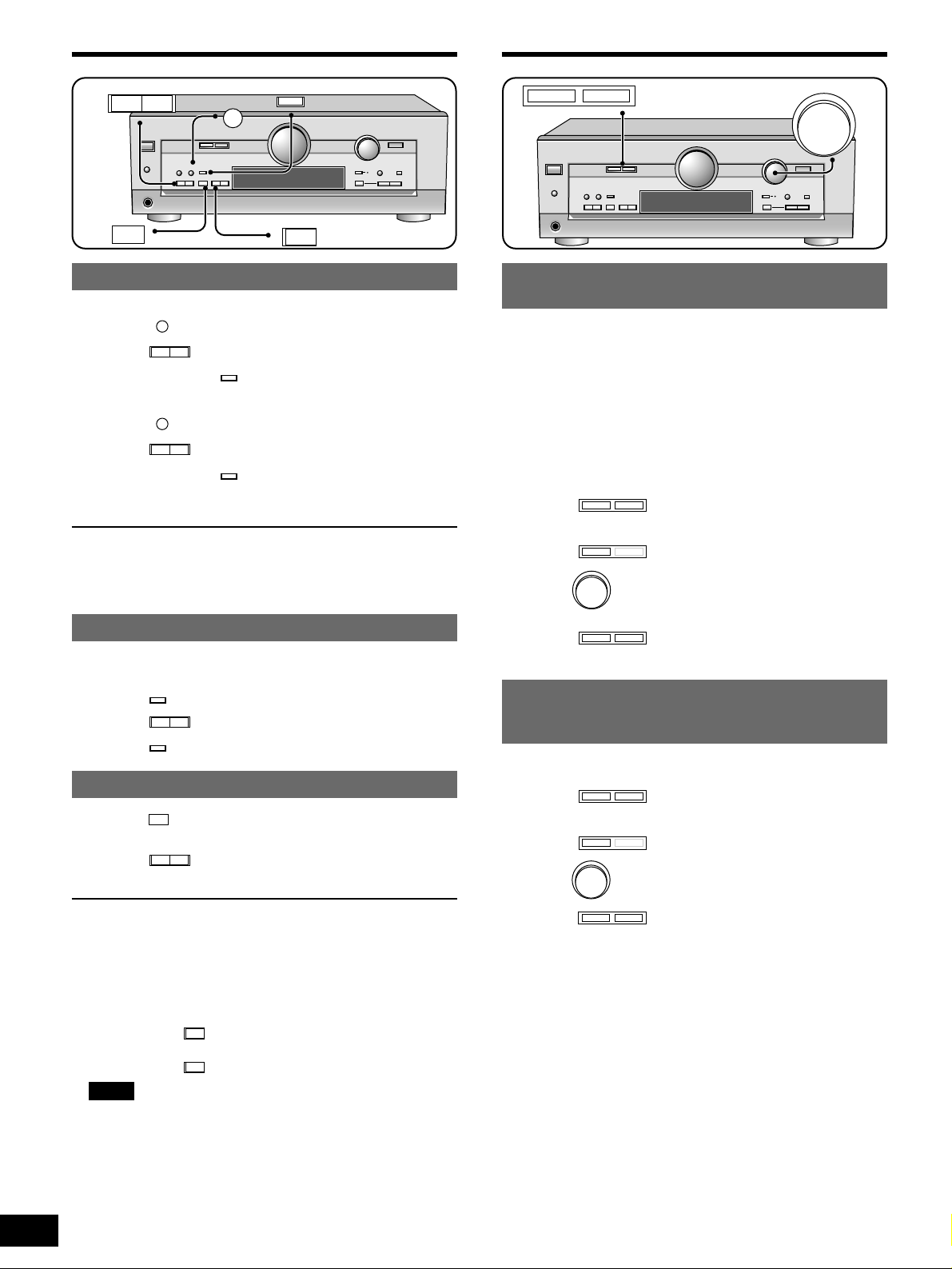
14
RQT6361
Change this setting to listen to software recorded with Dolby Digital
at low volume (such as late at night) and maintain audio clarity. It
reduces the peak level in loud scenes without affecting the sound
field.
OFF: The software is played with the original dynamic range
(factory setting).
STANDARD: The level recommended by the producer of the
software for household viewing.
MAX: The maximum allowable compression (recommended for
night viewing).
11
Press [ ] at the same time to enter
the setting mode.
22
Press [ ] to select “DR-COMP”.
33
Turn [ ] to select “OFF”, “STANDARD” or
“MAX”.
44
Press [ ] at the same time to exit
the setting mode.
SFC MODE
wq
INPUT SELECTOR
SFC MODE
w q
SFC MODE
wq
The factory setting is OFF (normal brightness).
11
Press [ ] at the same time to enter
the setting mode.
22
Press [ ] to select “DIMMER”.
33
Turn [ ] to select “OFF” or “ON”.
44
Press [ ] at the same time to exit
the setting mode.
SFC MODE
wq
INPUT SELECTOR
SFC MODE
w q
SFC MODE
wq
Preset the stations one at a time.
11
Tune to the station.
22
Press [ ].
33
Press [ ] to select a channel.
44
Press [ ].
MEMORY
TUNING
21
MEMORY
11
Press [ ] to select “FM”.
22
Press [ ] to tune to “FM 87.9 MHz”.
33
Press and hold [ ].
The FM stations the unit can receive are preset in channels 1 to 30.
44
Press [ ] to select “AM”.
55
Press [ ] to tune to “AM 530 kHz”.
66
Press and hold [ ].
The AM stations the unit can receive are preset in channels 21 to 30.
(FM stations are replaced if any were preset in these channels.)
During automatic presetting, the memory indicator (˜) flashes and
the frequency scrolls. The memory indicator and channel numbers
are displayed for a second when a station is preset.
The last station to be preset is displayed when presetting finishes.
MEMORY
TUNING
21
- BAND
– FM MODE
MEMORY
TUNING
21
- BAND
– FM MODE
11
Press [ ].
The channel number flashes for about 5 seconds.
22
Press [ ].
Hold down the buttons to change channels faster.
For your reference
Even if the power supply cord is disconnected from the household
AC outlet, the stations remain in memory for approximately one
month.
Improving reception
¡ DSP DEFEAT
Press and hold [ ] until “DEFEAT” appears.
Press and hold [ ] again to turn the DSP on.
While the DSP is defeated, you cannot:
– Select DSP sound modes,
– Adjust the tone,
– Output a test signal,
– Adjust individual speaker output, or
– Use digital input.
¡For your reference
DVD players can interfere with radio reception. Turn the DVD
player off or move it further away from the antennas if this occurs.
Note
DSP
SOUND MODE
DSP
SOUND MODE
TUNING
21
PRESET
Presetting Other settings
DR COMP –
Dynamic range compression
DIMMER –
Dim the unit’s display for better viewing in a
darkened room
Automatic presetting
Manual presetting
Selecting channels
POWER
SPEAKERS
SFC MODE
DOWN UP
VOLUME
INPUT SELECTOR
DVD 6CH INPUTSUBWOOFERTAPE MONITOR
BASS/TREBLE
34
BALANCE L R
DIGITAL INPUT
PHONES
- HELP
– RESET
- BAND
– FM MODE
MEMORY
TUNING
PRESET
DSP
SOUND MODE
DOLBY
PRO LOGIC 2
8
2wq1
DSP
SOUND MODE
TUNING
MEMORY
PRESET
21
- BAND
– FM MODE
POWER
SPEAKERS
SFC MODE
DOWN UP
VOLUME
INPUT SELECTOR
DVD 6CH INPUTSUBWOOFERTAPE MONITOR
BASS/TREBLE
34
BALANCE L R
DIGITAL INPUT
PHONES
- HELP
– RESET
- BAND
– FM MODE
MEMORY
TUNING
PRESET
DSP
SOUND MODE
DOLBY
PRO LOGIC 2
8
2wq1
INPUT SELECTOR
SFC MODE
wq
Page 15
15
RQT6361
L
R
L
R
FM
ANT
AM
ANT
GND
LOOP
EXT
75Ω
R L
Y
P
B
P
R
COMPONENT VIDEO
DIGITAL IN
TV VCR DVD/DVD 6CH
CD TAPE TV
FRONT
TV
MONITOR OUT
OPTICAL1
(TV)
OPTICAL2
(DVD)
REC
(OUT)
PLAY
(IN)
OUT IN
COAXIAL
DVDINTV
IN
MONITOR
OUT
MONITOR
OUT
CENTER
SURROUND
IN
IN
L
R
IN
SUBWOOFER
IN
IN
IN
S-VIDEO
TV TV VCR DVD
SURROUNDSUB
WOOFER
6 5 4
5–12 m
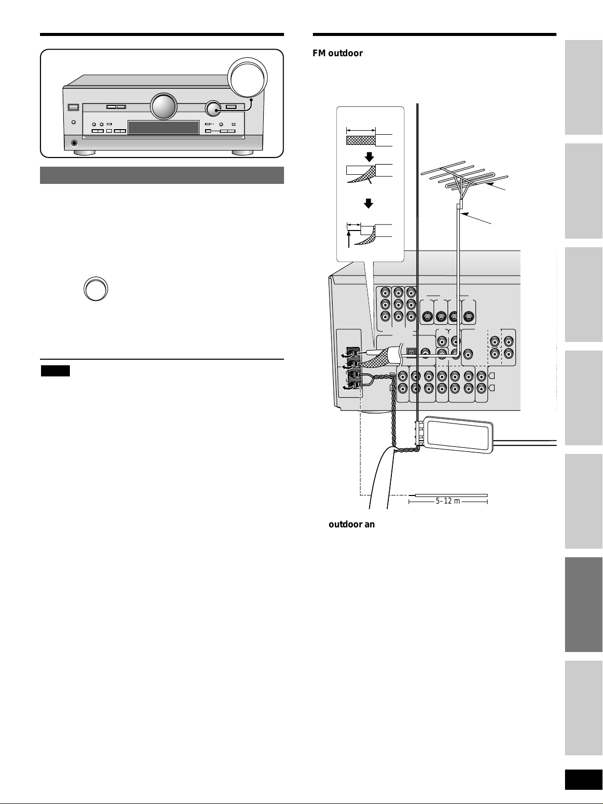
FM outdoor antenna
¡Disconnect the FM indoor antenna.
¡The antenna should be installed by a competent technician.
¡Twist the coaxial cable’s shield braid firmly and connect it to the
GND terminal.
AM outdoor antenna
¡Run a piece of vinyl wire horizontally across a window or other
convenient location.
¡Leave the loop antenna connected.
¡Disconnect the antenna when the unit is not in use. Do not use
the antenna during an electrical storm.
20 mm (25/32")
10 mm (3/8")
Shield braid
Core wire
FM outdoor antenna
75 Ω coaxial cable
You can record to a tape deck connected to TAPE REC (OUT) or to
a VCR connected to VCR OUT.
See the recording unit’s operating instructions for details on how to
prepare it for recording.
When recording with a tape deck, you can record any source
except TAPE.
When recording with a VCR, you can record any source except
TAPE or VCR.
11
Turn [ ] to select the source to be recorded.
22
Begin recording.
Follow your recording unit’s operating instructions.
33
Start the source to be recorded.
Follow your equipment’s operating instructions.
¡You cannot record a source connected through a digital terminal.
When recording CD, DVD, or TV, ensure the source is connected
through the corresponding analog terminals and “ANALOG” input
is selected.
¡When you select DVD 6CH INPUT mode, only sound from the
front left and right channels is recorded.
Note
INPUT SELECTOR
Recording on a tape deck or VCR
Making a recording Using outdoor antennas
Vinyl-covered wire
(16–40 ft)
Step 1
Step 2
Step 3
Before use
POWER
SPEAKERS
SFC MODE
DOWN UP
VOLUME
INPUT SELECTOR
DVD 6CH INPUTSUBWOOFERTAPE MONITOR
BASS/TREBLE
34
BALANCE L R
DIGITAL INPUT
PHONES
- HELP
– RESET
- BAND
– FM MODE
MEMORY
TUNING
PRESET
DSP
SOUND MODE
DOLBY
PRO LOGIC 2
8
2wq1
INPUT SELECTOR
AM loop antenna (included)
Step 4
Others
Reference
Page 16
16
RQT6361
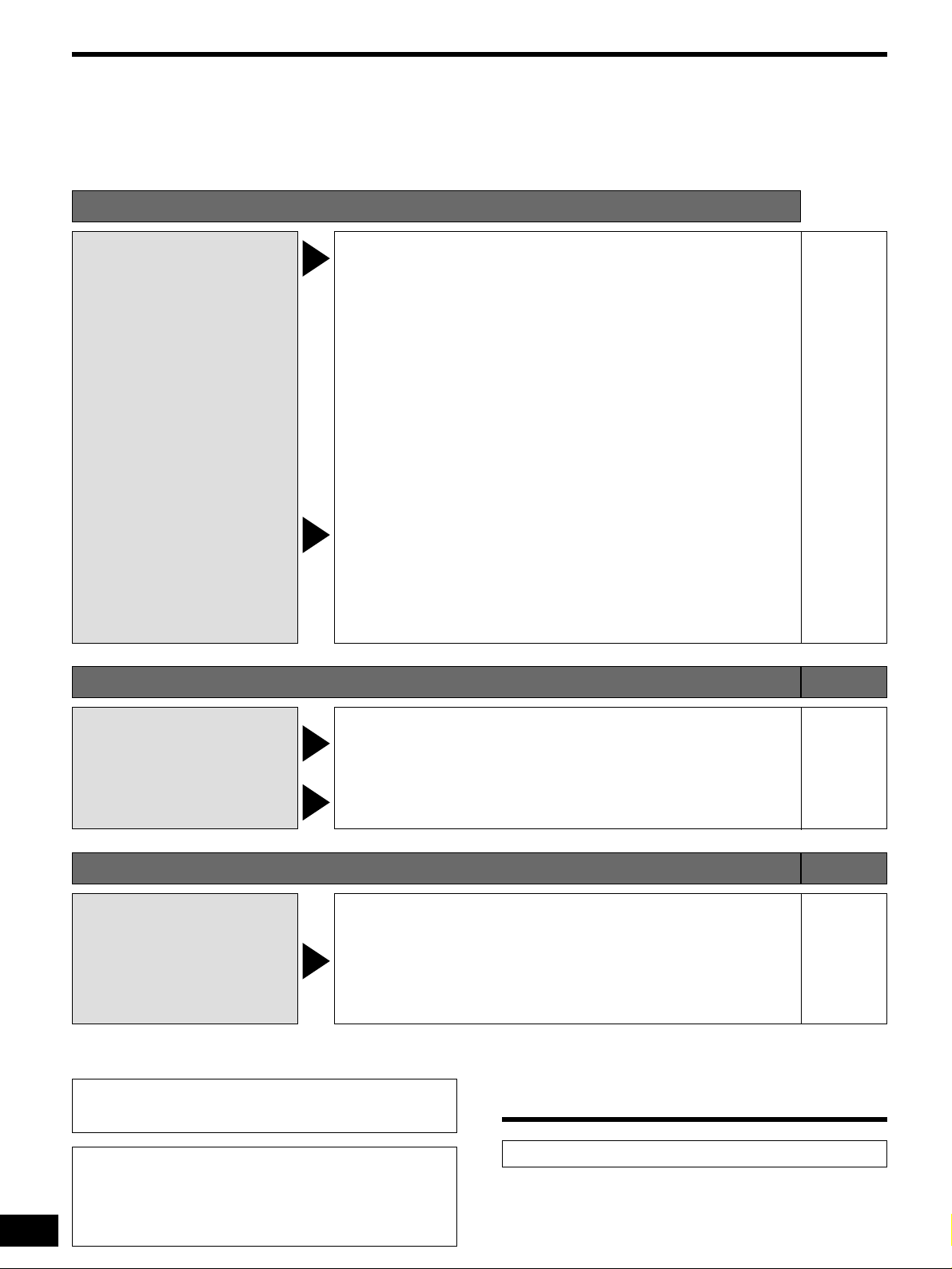
Troubleshooting guide
Before requesting service, make the below checks. If you are in doubt about some of the check points, or if the remedies indicated in
the chart do not solve the problem:
In the U.S.A., contact the Panasonic Customer Call Center at 1-800-211-7262, or e-mail [email protected], or web site
(http://www.panasonic.com).
In Canada, contact Panasonic Canada Inc. Customer Care Centre at 905-624-5505, or web site (www.panasonic.ca), or an authorized
Servicentre closest to you.
¡Connect the appropriate antenna. (You may need an outdoor antenna or one
with more elements.)
¡Adjust the position of the FM or AM antenna.
¡Reduce the treble.
¡Select “DSP DEFEAT”.
¡Turn off nearby televisions, video decks, DVD players, and satellite receivers.
¡Separate the antenna from other cables, leads, and appliances.
The radio cannot be tuned in or
there is a lot of noise and
interference.
7, 15
7
13
14
–
–
¡Ensure the SIZE settings for your speakers are correct.
¡Check the DSP sound mode.
¡Cancel “DSP DEFEAT”.
Sound is not heard from the
center, surround, or subwoofer
speakers.
8–9
10
14
¡Cancel “DSP DEFEAT”.
¡Turn DVD 6CH INPUT off.
DSP sound modes cannot be
selected.
14
13
To clean this unit, wipe with a soft, dry cloth.
¡Never use alcohol, paint thinner or benzine to clean this unit.
¡Before using chemically treated cloth, read the instructions that
came with the cloth carefully.
If the surfaces are dirty
Maintenance
Manufactured under license from Dolby Laboratories.
“Dolby”, “Pro Logic” and the double-D symbol are trademarks of
Dolby Laboratories.
Manufactured under license from Digital Theater Systems, Inc.
US Pat. No. 5,451,942, 5,956,674, 5,974,380, 5,978,762 and
other world-wide patents issued and pending. “DTS” and “DTS
Digital Surround” are registered trademarks of Digital Theater
Systems, Inc. c 1996, 2000 Digital Theater Systems, Inc. All
rights reserved.
DSP sound modes
Pages
Radio
Pages
Common problems
¡Ensure the power cord is connected.
No power.
¡Switch off the unit, determine and correct the cause, then switch the unit on.
Causes include:
–Shorting (bare wires touching) of positive and negative speaker wires.
–
Page 17
17
RQT6361
Specifications
(IHF’78)
■ AMPLIFIER SECTION
Rated minimum sine wave RMS power output
40 Hz–20 kHz both channels driven
0.9 % total harmonic distortion 100 W per channel (6 Ω)
1 kHz continuous power output both channels driven
0.05 % total harmonic distortion 105 W per channel (6 Ω)
Total harmonic distortion
rated power at 40 Hz–20 kHz 0.9 % (6 Ω)
half power at 1 kHz 0.07 % (6 Ω)
Power output at 1kHz each channel driven
0.9 % total harmonic distortion
Front 2 x 100 W (6 Ω)
Center 100 W (6 Ω)
Surround 2 x 100 W (6 Ω)
Subwoofer (f=100 Hz) 100 W (6 Ω)
Low frequency damping factor 30 (6 Ω)
Load impedance
Front 6–8 Ω
Center 6–8 Ω
Surround 6–8 Ω
Subwoofer 6–8 Ω
Dynamic headroom 2 dB (6 Ω)
Frequency response
CD, TAPE, DVD, TV, VCR 10 Hz–70 kHz, ±3 dB
Input sensitivity
CD, TAPE, DVD, TV, VCR 27 mV (200 mV, IHF ’66)
S/N (IHF A)
CD, TAPE, DVD, TV, VCR 75 dB (85 dB, IHF ’66)
Input impedance
CD, TAPE, DVD, TV, VCR 22 kΩ
Tone controls
BASS 50 Hz, +10 to –10 dB
TREBLE 20 kHz, +10 to –10 dB
Subwoofer frequency response (–6 dB) 7–200 Hz
Digital input
Optical 2
Coaxial 1
■ FM TUNER SECTION
Frequency range 87.9–107.9 MHz
Sensitivity 11.2 dBf (2 µV, IHF ’58)
50 dB quieting sensitivity
MONO 18.3 dBf (4.5 µV, IHF ’58)
STEREO 38.3 dBf (45 µV, IHF ’58)
Total harmonic distortion
MONO 0.2 %
STEREO 0.3 %
S/N
MONO 73 dB
STEREO 67 dB
Frequency response 20 Hz–15 kHz, +1 dB, –2 dB
Alternate channel selectivity 65 dB
Capture ratio 1.5 dB
Image rejection at 98 MHz 40 dB
Spurious response rejection at 98 MHz 75 dB
AM suppression 50 dB
Stereo separation
1 kHz 40 dB
10 kHz 30 dB
Antenna terminal 75 Ω (unbalanced)
■ AM TUNER SECTION
Frequency range 530–1710 kHz
Sensitivity 20 µV, 330 µV/m
Selectivity 55 dB
IF rejection at 1000 kHz 50 dB
■ VIDEO SECTION
Output voltage at 1 V input (unbalanced) 1±0.1 Vp-p
Maximum input voltage 1.5 Vp-p
Input/output impedance 75 Ω
■ GENERAL
Power supply AC 120 V, 60 Hz
Power consumption 450 VA, 350 W
Dimensions (W x H x D) 430 x 158 x 370 mm
(16-15/16'' x 6-7/32'' x 14-19/32'')
Mass 10.5 kg (23.1 lb.)
Power consumption in standby mode: 1 W
Step 1
Step 2
Step 3
Before use
Receiver
■ Front, center, and surround speakers (SB-AFC280)
Type 2 way 2 speaker Bass-ref.
Speaker unit
Woofer 10 cm cone type
Tweeter 6 cm cone type
Impedance 8 Ω
Input power
MUSIC 200 W
DIN 100 W
Sound pressure level 81 dB/W (1.0 m)
Crossover frequency 3.5 kHz
Frequency range 65 Hz–22 kHz (–16 dB)
95 Hz–20 kHz (–10 dB)
Dimensions (W x H x D) 120 x 208 x 163 mm
(4-3/4'' x 8-3/16'' x 6-7/16'')
Mass 1.8 kg (4.0 lb.)
■ Subwoofer (SB-W280)
Type 1 way 2 speaker Bass-ref.
Speaker unit
Woofer 14 cm cone type x 2
Impedance 8 Ω
Input power
MUSIC 200 W
DIN 100 W
Sound pressure level 80 dB/W (1.0 m)
Frequency range 39 Hz–1.9 kHz (–16 dB)
42 Hz–1.7 kHz (–10 dB)
Dimensions (W x H x D) 200 x 450 x 350 mm
(7-7/8'' x 17-23/32'' x 13-25/32'')
Mass 6.9 kg (15.2 lb.)
Notes:
1. Specifications are subject to change without notice.
Mass and dimensions are approximate.
2. Total harmonic distortion is measured by the digital spectrum
analyzer.
Speakers
Step 4
Others
Reference
Page 18
18
RQT6361
Warranty (U.S.A.)
Panasonic Consumer Electronics Company,
Division of Matsushita Electric Corporation of America
One Panasonic Way Secaucus, New Jersey 07094
Panasonic/Technics Audio Products
Limited Warranty
Panasonic Consumer Electronics Company or Panasonic Sales Company
(collectively referred to as “the Warrantor”) will repair or replace this product
with new or refurbished parts or equivalent product, free of charge in the
U.S.A. or Puerto Rico, in the event of a defect in materials or workmanship
as follows (all time periods commerce from the date of original purchase):
AUDIO PRODUCTS
–labor and parts for one (1) year.
ALL AUDIO RACKS (cabinets)
–parts only 30 days.
TECHNICS STAND ALONE SPEAKERS, SUBWOOFER SPEAKERS
–
labor and parts for three (3) years.
USB READER-WRITER, PERSONAL COMPUTER CARD ADAPTERS
–
(when applicable)–exchange defective unit with a new or refurbished one
for one (1) year.
ACCESSORIES–HEADPHONES, CARTRIDGES, MICROPHONES,
ADAPTERS
–labor and parts for ninety (90) days.
RECHARGEABLE BATTERIES
–(when applicable)–exchange defective
item for new one for ten (10) days. Non-rechargeable batteries are not
warranted.
SD MEMORY CARDS, RECHARGEABLE BATTERY PACK
–(when
applicable)–exchange defective item for new one for ninety (90) days. Nonrechargeable battery packs are not warranted.
Carry-in or mail-in service in the U.S.A. can be obtained during the
warranty period by contacting a Panasonic Services Company (PASC)
Factory Servicenter listed in the Servicenter Directory. Or call toll free,
1-800-211-7262 to locate a PASC authorized Servicenter. Carry-in or mail-in
service in Puerto Rico can be obtained during the warranty period by calling
the Panasonic Sales Company telephone number listed in the Servicenter
Directory.
This warranty is extended only to the original purchaser. A purchase
receipt or other proof of date of original purchase will be required before
warranty service is rendered.
This warranty only covers failures due to defects in materials and
workmanship which occur during normal use and does not cover normal
wear to the stylus (when applicable) or a dealer installed cartridge or stylus.
The warranty does not cover damages which occur in shipment or failures
which are caused by products not supplied by the warrantor, or failures
which result from accident, misuse, abuse, neglect, mishandling, faulty
installation, misapplication, set-up adjustments, maladjustment of consumer
controls, improper operation or maintenance, improper antenna, inadequate
signal reception or pick-up, alteration, modification, power line surge,
improper voltage supply, lightning damage, commercial use, such as; hotel,
office, restaurant, or other business or rental use of the product, or service
by anyone other than a PASC Factory Servicenter or a PASC authorized
Servicenter, or damage that is attributable to acts of God.
LIMITS AND EXCLUSIONS
There are no express warranties except as listed above.
THE WARRANTOR SHALL NOT BE LIABLE FOR INCIDENTAL OR
CONSEQUENTIAL DAMAGES RESULTING FROM THE USE OF THIS
PRODUCT, OR ARISING OUT OF ANY BREACH OF THIS WARRANTY,
INCLUDING WITHOUT LIMITATION, DAMAGE TO TAPES, RECORDS
OR DISCS. ALL EXPRESS AND IMPLIED WARRANTIES, INCLUDING
THE WARRANTIES OF MERCHANTABILITY, AND FITNESS FOR A
PARTICULAR PURPOSE, ARE LIMITED TO THE APPLICABLE
WARRANTY PERIOD SET FORTH ABOVE. Some states do not allow the
exclusion or limitation of incidental or consequential damages, or limitations
on how long an implied warranty lasts, so the above exclusions or
limitations may not apply to you.
This warranty gives you specific legal rights and you may also have other
rights which vary from state to state.
If a problem with this product develops during or after the warranty
period, you may contact your dealer or Servicenter. If the problem is not
handled to your satisfaction, then write to the Consumer Affairs Department
at the company address indicated above.
Panasonic Sales Company, Division of Matsushita Electric
of Puerto Rico, Inc.
Ave. 65 de Infantería, Km. 9.5
San Gabriel Industrial Park, Carolina, Puerto Rico 00985
If you ship the product
Carefully pack and send it prepaid, adequately insured and preferably in the original carton.
Attach a postage-affixed letter, detailing the complaint, to the outside of the carton.
Do NOT send the product to the Executive or Regional Sales offices. They are NOT equipped to make repairs.
For product information or assistance with product operation:
In the U.S.A., contact the Panasonic Customer Call Center at 1800-211-7262, or e-mail [email protected], or
web site (http://www.panasonic.com).
In Canada, contact Panasonic Canada Inc. Customer Care Centre
at 905-624-5505, web site (www.panasonic.ca), or an authorized
Servicentre closest to you.
Product information
1. Damage requiring service — The unit should be serviced by
qualified service personnel if:
(a) The AC power supply cord or the plug has been damaged; or
(b) Objects or liquids have gotten into the unit; or
(c) The unit has been exposed to rain; or
(d) The unit does not operate normally or exhibits a marked
change in performance; or
(e) The unit has been dropped or the cabinet damaged.
2. Servicing — Do not attempt to service the unit beyond that
described in these operating instructions. Refer all other
servicing to authorized servicing personnel.
3. Replacement parts — When parts need replacing ensure the
servicer uses parts specified by the manufacturer or parts that
have the same characteristics as the original parts.
Unauthorized substitutes may result in fire, electric shock, or
other hazards.
4. Safety check — After repairs or service, ask the servicer to
perform safety checks to confirm that the unit is in proper
working condition.
Product Service
Page 19
19
RQT6361
Servicenter List (U.S.A.)
Step 1
Step 2
Step 3
Before use
Step 4
Others
Reference
Page 20
Panasonic Consumer Electronics
Company, Division of Matsushita
Electric Corporation of America
One Panasonic Way Secaucus,
New Jersey 07094
http://www.panasonic.com
Panasonic Sales Company,
Division of Matsushita Electric of
Puerto Rico, Inc. (“PSC”)
Ave. 65 de Infantería, Km. 9.5
San Gabriel Industrial Park, Carolina,
Puerto Rico 00985
Panasonic Canada Inc.
5770 Ambler Drive
Mississauga, Ontario
L4W 2T3
www.panasonic.ca
En
2002 Matsushita Electric Industrial Co., Ltd.
Printed in Malaysia
RQT6361-P
H0102RF0
As an ENERGY STAR®Partner, Panasonic
has determined that this product meets the
ENERGY STAR
®
guidelines for energy
efficiency.
The model number and serial number of this product can be
found on either the back or the bottom of the unit.
Please note them in the space provided below and keep for
future reference.
MODEL NUMBER SERIAL NUMBER
Receiver: ___________________ ___________________
Front, center, surround speakers:
___________________ ___________________
Subwoofer:
___________________ ___________________
DATE OF PURCHASE __________________________
DEALER NAME _______________________________
DEALER ADDRESS ____________________________
_____________________________________________
TELEPHONE NUMBER _________________________
User memo:
SA-HT400
CAUTION:
This equipment has been tested and found to comply with the
limits for a Class B digital device, pursuant to Part 15 of the
FCC Rules.
 Loading...