

Panasonic SC-BT737, SC-BT337, SC-BT230 Operating Instructions Manual
Operating Instructions
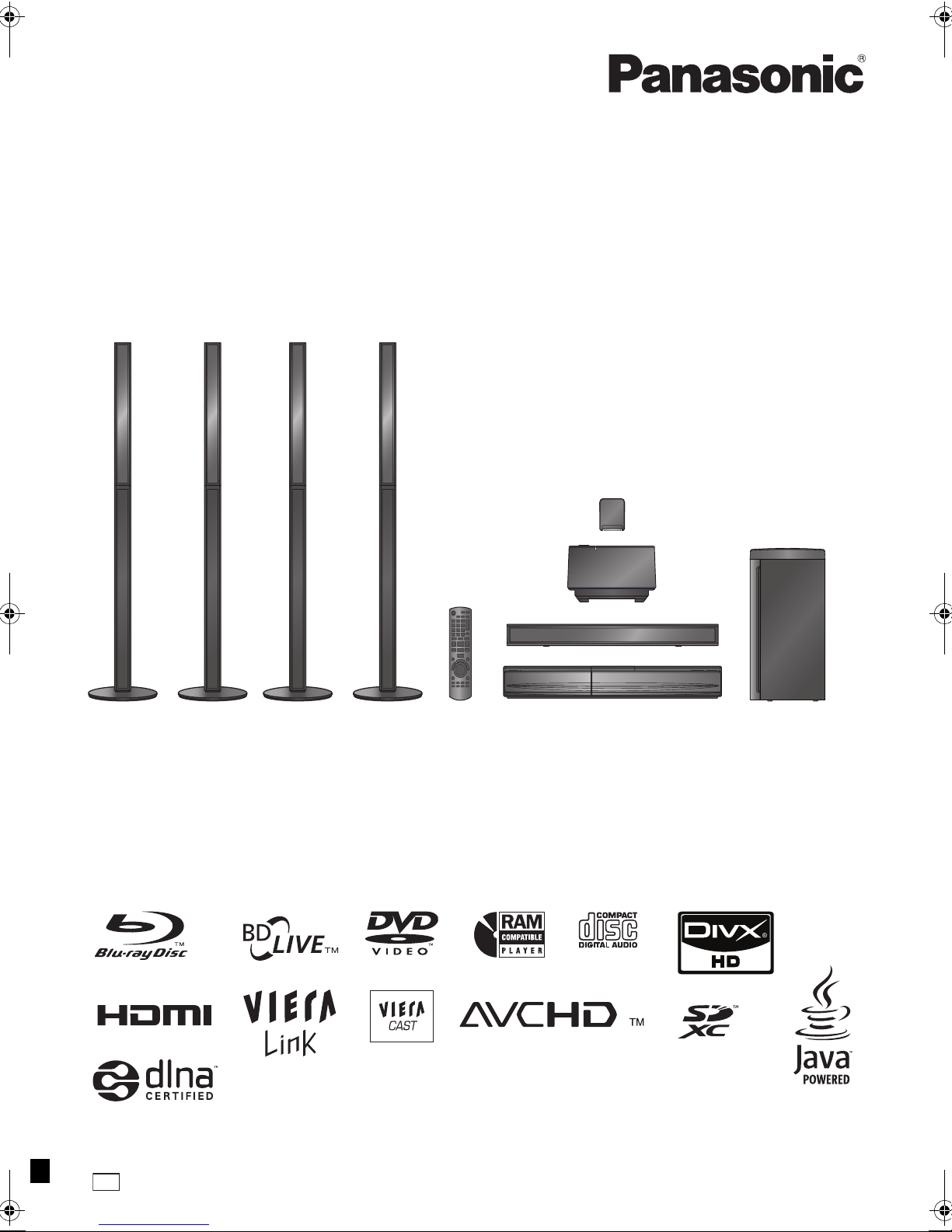
Blu-ray Disc Home Theater Sound System
Model No. SC-BT737
SC-BT337
SC-BT230
The illustration shows the image of the unit SC-BT737.
Dear customer
Thank you for purchasing this product.
For optimum performance and safety, please read these instructions carefully.
Before connecting, operating or adjusting this product, please read the instructions completely.
Please keep this manual for future reference.
GN
VQT2Q55
Getting started
CAUTION!
THIS PRODUCT UTILIZES A LASER.
USE OF CONTROLS OR ADJUSTMENTS OR
PERFORMANCE OF PROCEDURES OTHER THAN
THOSE SPECIFIED HEREIN MAY RESULT IN
HAZARDOUS RADIATION EXPOSURE.
DO NOT OPEN COVERS AND DO NOT REPAIR
YOURSELF. REFER SERVICING TO QUALIFIED
PERSONNEL.
CAUTION!
≥ DO NOT INSTALL OR PLACE THIS UNIT IN A
BOOKCASE, BUILT-IN CABINET OR IN ANOTHER
CONFINED SPACE. ENSURE THE UNIT IS WELL
VENTILATED. TO PREVENT RISK OF ELECTRIC
SHOCK OR FIRE HAZARD DUE TO OVERHEATING,
ENSURE THAT CURTAINS AND ANY OTHER
MATERIALS DO NOT OBSTRUCT THE VENTILATION
VENTS.
≥ DO NOT OBSTRUCT THE UNIT’S VENTILATION
OPENINGS WITH NEWSPAPERS, TABLECLOTHS,
CURTAINS, AND SIMILAR ITEMS.
≥ DO NOT PLACE SOURCES OF NAKED FLAMES,
SUCH AS LIGHTED CANDLES, ON THE UNIT.
≥ DISPOSE OF BATTERIES IN AN ENVIRONMENTALLY
FRIENDLY MANNER.
WARNING:
TO REDUCE THE RISK OF FIRE, ELECTRIC SHOCK OR
PRODUCT DAMAGE,
≥ DO NOT EXPOSE THIS APPARATUS TO RAIN,
MOISTURE, DRIPPING OR SPLASHING AND THAT
NO OBJECTS FILLED WITH LIQUIDS, SUCH AS
VASES, SHALL BE PLACED ON THE APPARATUS.
≥ USE ONLY THE RECOMMENDED ACCESSORIES.
≥ DO NOT REMOVE THE COVER (OR BACK); THERE
ARE NO USER SERVICEABLE PARTS INSIDE.
REFER SERVICING TO QUALIFIED SERVICE
PERSONNEL.
THIS UNIT IS INTENDED FOR USE IN MODERATE
CLIMATES.
This product may receive radio interference caused by
mobile telephones during use. If such interference is
apparent, please increase separation between the product
and the mobile telephone.
[BT737] [BT337]
For wireless system
Product Identification Marking is located on the bottom of
wireless system.
Safety precautions
Placement
Set the unit up on an even surface away from direct sunlight,
high temperatures, high humidity, and excessive vibration.
These conditions can damage the cabinet and other
components, thereby shortening the unit’s service life. Do not
place heavy items on the unit.
Voltage
Do not use high voltage power sources. This can overload the
unit and cause a fire. Do not use a DC power source. Check
the source carefully when setting the unit up on a ship or other
place where DC is used.
AC mains lead protection
Ensure the AC mains lead is connected correctly and not
damaged. Poor connection and lead damage can cause fire or
electric shock. Do not pull, bend, or place heavy items on the
lead.
Grasp the plug firmly when unplugging the lead. Pulling the AC
mains lead can cause electric shock. Do not handle the plug
with wet hands. This can cause electric shock.
Foreign matter
Do not let metal objects fall inside the unit. This can cause
electric shock or malfunction.
Do not let liquids get into the unit. This can cause electric
shock or malfunction. If this occurs, immediately disconnect
the unit from the power supply and contact your dealer.
Do not spray insecticides onto or into the unit. They contain
flammable gases which can ignite if sprayed into the unit.
Service
Do not attempt to repair this unit by yourself. If sound is
interrupted, indicators fail to light, smoke appears, or any other
problem that is not covered in these instructions occurs,
disconnect the AC mains lead and contact your dealer or an
authorized service centre. Electric shock or damage to the unit
can occur if the unit is repaired, disassembled or reconstructed
by unqualified persons.
Extend operating life by disconnecting the unit from the power
source if it is not to be used for a long time.
VQT2Q55
2
Unit and media care
R6/LR6, AA
(Alkaline or manganese
batteries)
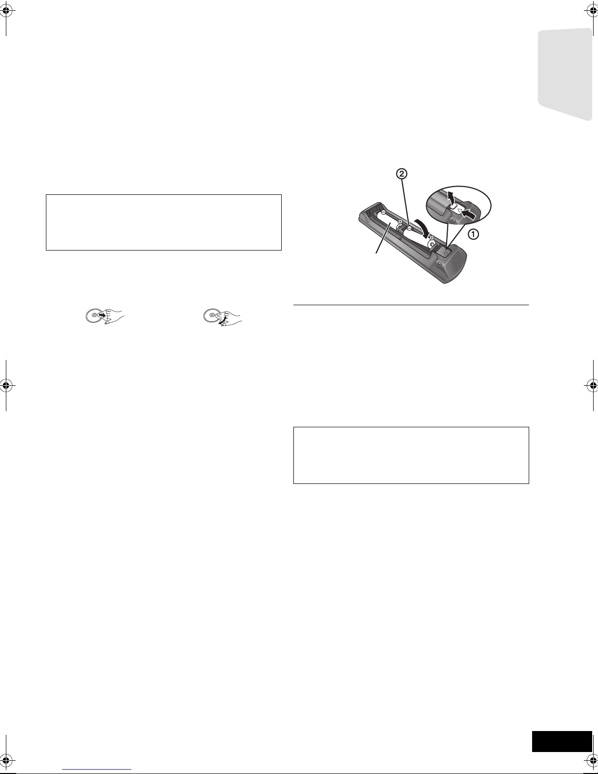
Using the remote
Getting started
∫ Clean this unit with a soft, dry cloth
≥ Never use alcohol, paint thinner or benzine to clean this unit.
≥ Before using chemically treated cloth, carefully read the
instructions that came with the cloth.
∫ Clean the lens with the lens cleaner
Lens cleaner: RP-CL720E
≥ This lens cleaner may not be for sale depending on the
region.
≥ This lens cleaner is primarily for use on Panasonic DVD
recorders (DIGA), but it is also suitable for use on this unit.
∫ Clean discs
DO DO NOT
Wipe with a damp cloth and then wipe dry.
∫ Disc and card handling precautions
≥ Handle discs by the edges to avoid inadvertent scratches or
fingerprints on the disc.
≥ Do not attach labels or stickers to discs.
≥ Do not use record cleaning sprays, benzine, thinner, static
electricity prevention liquids or any other solvent.
≥ Clean any dust, water, or foreign matter from the terminals
on the rear side of the card.
≥ Do not use the following discs:
jDiscs with exposed adhesive from removed stickers or
labels (rented discs etc).
jDiscs that are badly warped or cracked.
jIrregularly shaped discs, such as heart shapes.
control
Insert so the poles (i and j) match those in the remote
control.
Point it at remote control signal sensor on this unit. (> 7)
Mishandling of batteries can cause electrolyte leakage which can damage
items the fluid contacts and may cause a fire.
≥ Do not mix old and new batteries or different types at the same time.
≥ Do not heat or expose to flame.
≥ Do not leave the battery(ies) in an automobile exposed to direct sunlight for
a long period of time with doors and windows closed.
≥ Do not take apart or short circuit.
≥ Do not attempt to recharge alkaline or manganese batteries.
≥ Do not use batteries if the covering has been peeled off.
Remove batteries if the remote control is not going to be used for a long
period of time. Store in a cool, dark place.
CAUTION
Danger of explosion if battery is incorrectly replaced.
Replace only with the same or equivalent type
recommended by the manufacturer. Dispose of used
batteries according to the manufacturer’s instructions.
∫ To dispose or transfer this unit
The unit may keep the user settings information in the unit. If
you discard this unit either by disposal or transfer, then follow
the procedure to return all the settings to the factory presets to
delete the user settings. (> 43, “To return to the factory
preset.”)
≥ The operation history may be recorded in the memory of this
unit.
VQT2Q55
3
Getting started
≥ These operating instructions are applicable to models
SC-BT737, SC-BT337 and SC-BT230. Unless otherwise
indicated, illustrations in these operating instructions
Indicates features applicable to:
[BT737]:
[BT337]
[BT230]:
SC-BT737only
: SC-BT337 only
SC-BT230 only
are of SC-BT737.
≥ Operations in these instructions are described mainly
with the remote control, but you can perform the
operations on the main unit if the controls are the
same.
System SC-BT737 SC-BT337 SC-BT230
Main unit SA-BT737 SA-BT337 SA-BT230
Speaker system Front speakers SB-HF730 SB-HF330 SB-HF230
Centre speaker SB-HC730 SB-HC230 SB-HC230
Surround speakers SB-HS735 SB-HS230 SB-HS230
Subwoofer SB-HW330 SB-HW330 SB-HW480
Wireless system (with a digital transmitter) SH-FX71 SH-FX71 —
≥Some models may not be on sale in certain regions.
≥Some accessories and external devices mentioned in these operating instructions that are not included with this
product may not be on sale in certain regions.
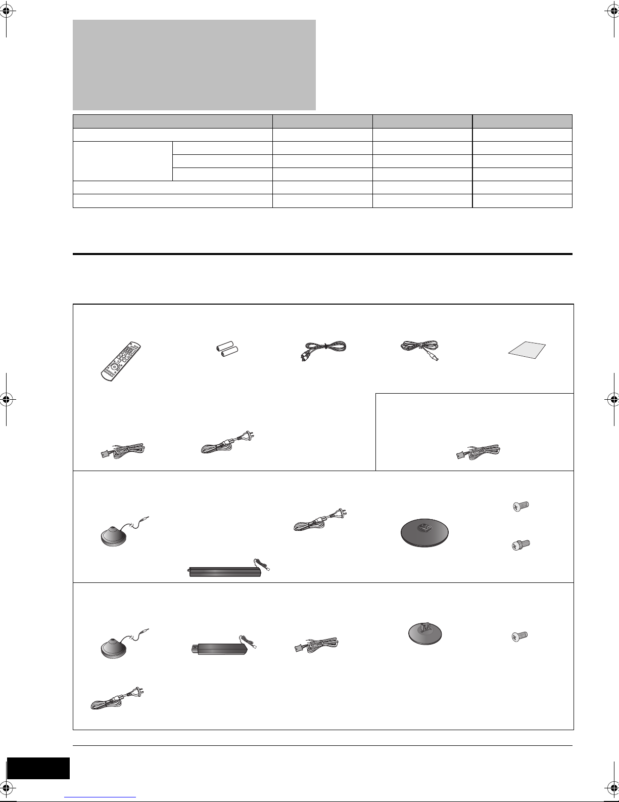
Accessory
Check the supplied accessories before using this unit.
[BT737] [BT337] [BT230]
∏ 1 Remote control
(N2QAKB000090)
∏ Speaker cable
≥ with green
connector(centre)
[BT737]
∏ 1 Auto speaker setup
microphone
[BT337]
∏ 1 Auto speaker setup
microphone
∏ 2Batteries for
remote control
∏ 1 AC mains lead
∏ 4 Speaker stands
(with cable)
≥ with red/white
connector (front)
≥ with grey/blue
connector
(surround)
∏ 2 Speaker stands
(with cable)
≥ with red/white
connector (front)
∏ 1 Video cable ∏ 1 FM indoor antenna ∏ 1 Sheet of speaker
cable stickers
[BT230]
∏ Speaker cables
≥ with red/white connector (front)
≥ with grey/blue connector (surround)
∏ 1 AC mains lead
For the wireless system
∏ Speaker cables
with grey/blue
≥
connector (surround)
∏ 4 Bases ∏ 8 Screws
4 Screws
∏ 2 Bases ∏ 8 Screws
∏ 1 AC mains lead
For the wireless system
VQT2Q55
≥ Product numbers correct as of February 2010. These may be subject to change.
4
≥ Do not use AC mains lead with other equipment.
Table of contents
Safety precautions ............................................. 2
Getting started
Unit and media care .......................................... 3
Using the remote control ................................... 3
Accessory .......................................................... 4
Control reference guide ..................................... 6
•Remote control .................................................................6
•Main unit (Front) ...............................................................7
•Main unit (Rear) ................................................................7
Playable discs/Cards/USB devices ................... 8
STEP 1: Preparing the speakers ..................... 10
•Assembling the speakers ...............................................10
•Speaker assembly option ...............................................11
STEP 2: Positioning ........................................ 12
STEP 3: Connections ...................................... 13
•Speaker cable connection ..............................................13
•Connection to a TV .........................................................14
•Radio antenna connection ..............................................16
•[BT737] [BT337] Digital Transmitter connection .................16
•Connection to a broadband network ...............................17
STEP 4 : AC mains lead connection ............... 18
STEP 5: [BT737] [BT337]
Preparing the wireless system ......................... 18
STEP 6: Smart setup / Easy setup .................. 19
•Network Easy Setting ....................................................20
•Firmware updating ..........................................................21
STEP 7:
Reprogramming the remote control ................. 22
TV
Enjoying TV with unit’s speakers .....................30
•Surround sound effects .................................................. 30
•Sound modes ................................................................. 30
•Making settings for digital audio input ............................ 30
Linked operations with the TV
(VIERA Link “HDAVI Control
•Setting the audio link ...................................................... 31
•Easy control only with VIERA remote control ................ 32
TM
”) ...................... 31
Other devices
Using the iPod/iPhone ..................................... 32
•iPod/iPhone Connection ................................................ 32
•iPod/iPhone Playback .................................................... 33
Advanced operations
Enjoying VIERA CAST ..................................... 34
Playback menu ................................................ 34
DLNA feature ................................................... 36
Setup menu .....................................................37
•Speaker settings ............................................................ 41
Optional speaker settings
Getting started TV Radio PlaybackOther devices
Inserting or removing a media ......................... 22
START menu ................................................... 23
Enjoying sound effects from all speakers ........ 24
•Enjoying surround sound effects ....................................24
Playback
Playing video contents .................................... 25
•Other operations during play ..........................................25
•Useful functions ..............................................................26
•Enjoying BD-Live or BONUSVIEW in BD-Video .............26
•Regarding DivX ..............................................................27
Playing music .................................................. 27
Playing still pictures ......................................... 28
•Useful functions ..............................................................28
Radio
Listening to the Radio ...................................... 29
•Presetting stations automatically ....................................29
•Presetting stations manually ...........................................29
•Listening/confirming the preset channels .......................29
Speaker installation option ............................... 42
Reference
Troubleshooting guide ..................................... 43
Messages ........................................................45
About MP3/JPEG/DivX/
AVCHD/MPEG2 files ....................................... 46
Supplemental information ................................ 47
Glossary ........................................................... 49
Specifications ...................................................50
Index ................................................. Back Cover
Advanced operations
settings
Optional speaker
Reference
VQT2Q55
5
Control reference guide
CANCEL
PIP
RETURN
VOL
STOP
1 2 3
4 5 6
7 809
VOL
TV
AV
SEARCH
SKIP
SLOW
SKIP
PLAY
PAUSE
SEARCH
OK
BD/SD
iPod
EXT-IN
MUTE
RADIO
P
O
P
-
U
P
M
E
N
U
T
O
P
M
E
N
U
EXIT
STATUS
OPTION
-
SLEEP
-
CH SELECT
SOUND
SURROUND
DISPLAY
AUDIO
abc
def
jkl
mno
tuv
ghi
qrs
p
xyz
w
D
I
R
E
C
T
N
A
V
I
G
A
T
O
R
19
8
21
22
24
13
15
20
1
4
18
2
23
14
16
17
3
5
6
7
9
10
11
12
S
T
A
R
T
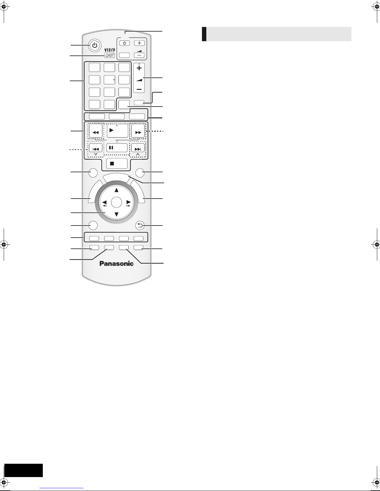
Remote control
1 Turn the unit on and off (> 19)
2 Display the Home screen of VIERA CAST (> 34)
3 Select title numbers, etc./Enter numbers or characters
(> 34)
[CANCEL] : Cancel
4 Basic playback control buttons (> 25)
5 Select preset radio stations (> 29)
6 Show status messages (> 25)
7 Show Top Menu/DIRECT NAVIGATOR (> 25)
8[3, 4, 2, 1]: Menu selection
[OK]: Selection
[2, 1]: Select preset radio station (> 29)
[2] (2;), [1] (;1): Frame-by-frame (> 25)
9 Show OPTION menu (> 26)
10 Coloured buttons (red, green yellow, blue)
These buttons are used when;
≥ Operating a BD-Video disc that includes Java
applications (BD-J).
≥ Displaying “Title View” and “Album View” screens.
(> 28)
≥ Operating contents of VIERA CAST (> 34)
11 Set the sound mode (> 24)/Select speaker channel
(> 24)
12 Select surround sound effects (> 24)
13 TV operation buttons
You can operate the TV through the unit’s remote control.
[Í]: Turn the television on and off
[AV]: Switch the input select
[ijVOL] : Adjust the volume
14 Adjust the volume of the main unit
15 Mute the sound
≥ “MUTE” flashes on the unit’s display, while the function is
on.
≥ To cancel, press the button again or adjust the volume.
≥ Muting is cancelled if the unit is turned off.
16 Switch on/off Secondary Video (Picture-in-picture) (> 26)
17 Select the source
[BD/SD]: Select disc drive or SD card drive (> 23)
[iPod]: Select iPod/iPhone as the source (> 23, 33)
[RADIO/EXT-IN]: Select FM tuner, USB or external audio
as the source (> 23, 29, 30)
18 Select radio stations manually (> 29)
19 Exit the menu screen
20 Show START menu (> 23)
21 Show Pop-up menu (> 25)
22 Return to previous screen
23 Select audio (> 25)
24 Show Playback menu (> 34)/Set the sleep timer
1 Press and hold [jSLEEP].
2 While “SLEEP ££” is displayed, press [jSLEEP]
several times to select the time (in minutes).
≥ Timer selection is up to 120 minutes.
≥ Select “OFF” when cancelling the setting.
≥ To confirm the remaining time
Press and hold the button again.
TM
VQT2Q55
6
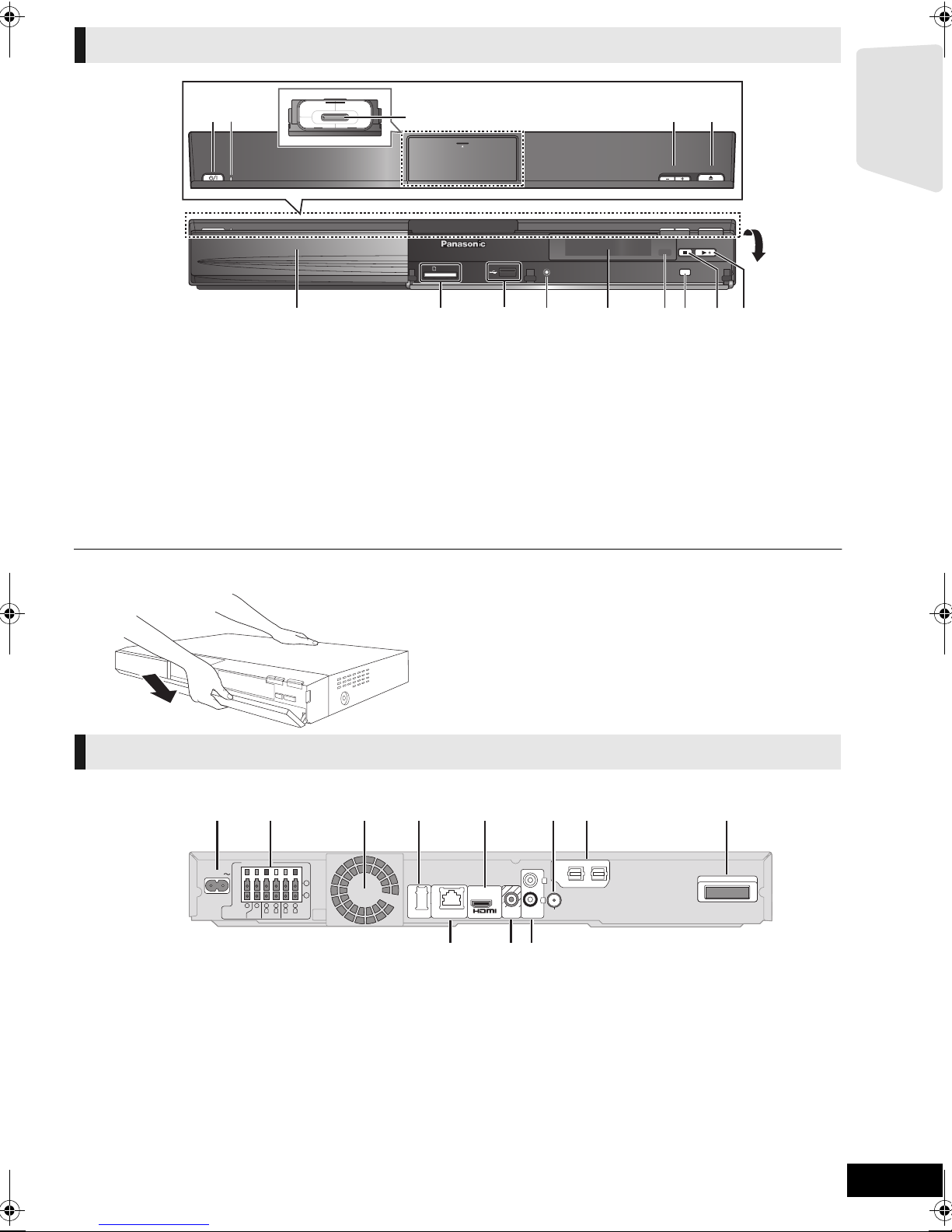
Main unit (Front)
OPEN/CLOSEVOLUME
iPod
SELECTOR
SD CARD
SETUP MIC
1 2
3
45
6 7 8 9 10 11 12 13
14
Pull open.
e.g., [BT737]
2
DIGITAL AUDIO IN
DIGITAL TRANSMITTER
VIDEO
OUT
AUX
LAN
WIRELESS
FM ANT
L
R
5
2
1
3Ω6Ω6
Ω
FRONT
CENTER
SUBWOOFER
R L
6
4
3
3
Ω
SURROUND
R L
(75Ω)
OPTICAL
2
DIGITAL AUDIO IN
DIGITAL TRANSMITTER
1
LAN
(
10BASE-T/
100BASE-TX
)
AC IN
(ARC)
AV
OUT
1 2 3 4 5 6 7 8
109 11
Getting started
1 Standby/on switch (Í/I) (> 19)
Press to switch the unit from on to standby mode or vice
versa. In standby mode, the unit is still consuming a small
amount of power.
2 Power indicator
The indicator lights when this unit is turned on.
3 Connect iPod/iPhone (> 32)
4 Adjust the volume of the main unit
5 Open or close the disc tray (> 22)
6 Disc tray
7 SD card slot (> 22)
∫ If the front cover comes off
Main unit (Rear)
8 USB port (> 22)
9 [BT737] [BT337] Connect Auto speaker setup microphone
10 Display (FL display)
≥ “SRD” (SURROUND) lights when sound is output to the
surround speakers.
11 Remote control signal sensor
Distance: within approx. 7 m.
Angle: Approx. 20e up and down, 30e left and right
12 Select the source (> 23)
13 Stop (> 25)
14 Start play (> 25)
1 Hold rear side of main unit by one hand and match up left
or right side protruding hook on the cover first with the
corresponding slot on the unit.
2 Push the hook firmly towards the unit until it clicks into
place. Then push the succeeding hooks one by one until
all have clicked into place.
3 Check that the cover now moves correctly.
≥ If it does not, remove it and repeat the above procedure.
1 AC IN terminal (> 18)
2 Speaker terminals (> 13)
3 Cooling fan
4 USB port for optional wireless adaptor (> 17)
5 HDMI AV OUT terminal (> 15)
6 FM radio antenna terminal (> 16)
8 Digital transmitter dock (> 12)
9LAN port (> 17)
10 VIDEO OUT terminal (> 14)
11 AUX terminal (> 14)
7 DIGITAL AUDIO IN terminals (> 14 , 15)
Terminal 1 is designated for connection with the TV.
Terminal 2 can be used with equipment other than the
STB.
Connect a digital transmitter when using an optional
wireless system.
VQT2Q55
7
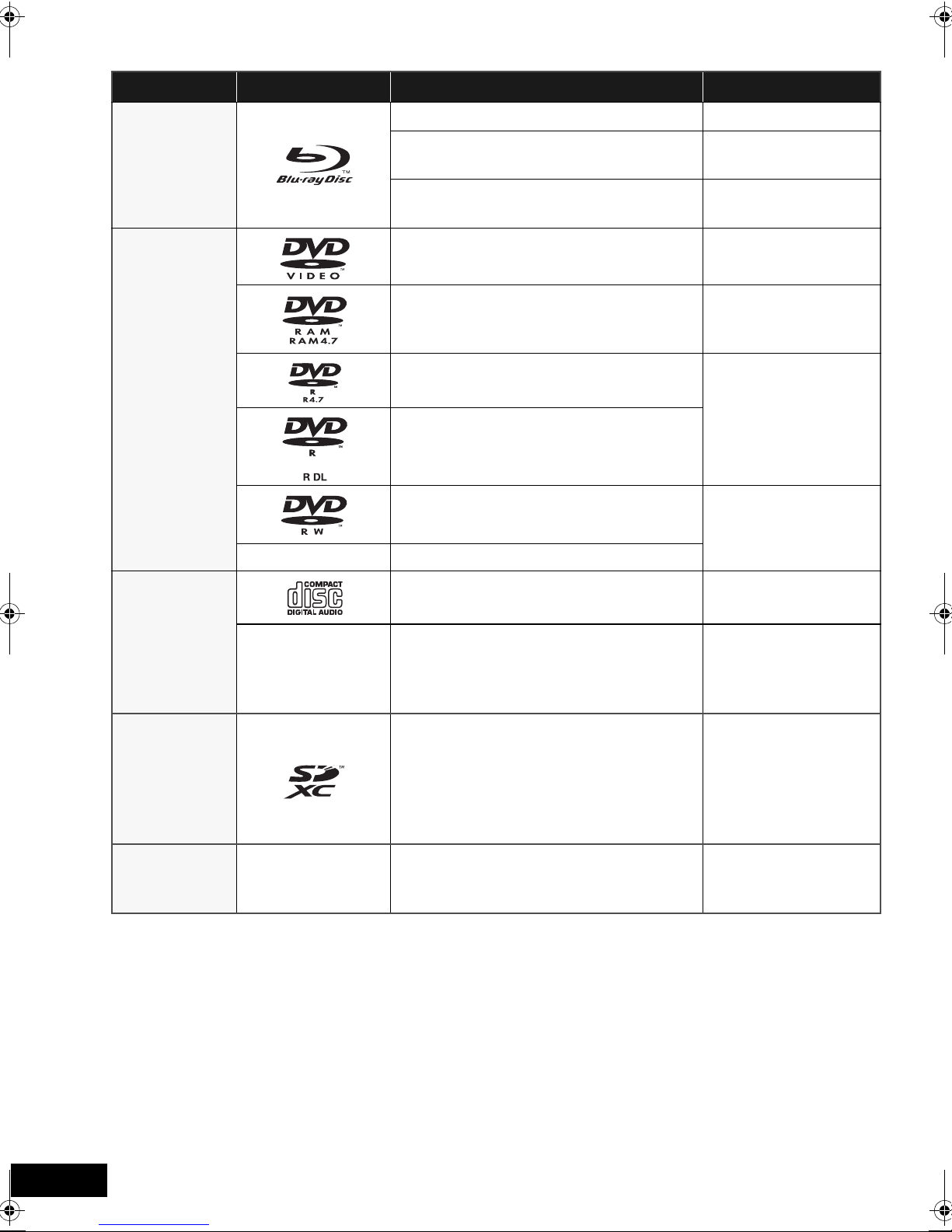
Playable discs/Cards/USB devices
Type Logo examples Type detail Playable contents*
BD-Video Video
[BD]
[DVD]
—
BD-RE
BD-R
Video
JPEG
Video
DivX
DVD-Video Video
Video
DVD-RAM
AVCHD
JPEG
DVD-R
Video
AVCHD
DivX
DVD-R DL
MP3
JPEG
DVD-RW
Video
AVCHD
+R/+RW/+R DL
®
Music CD Music [CD-DA]
[CD]
—
CD-R
CD-RW
SD Memory Card (8 MB to 2 GB)
(Includes miniSD Card and microSD Card)
SDHC Memory Card (4 GB to 32 GB)
[SD]
(Includes microSDHC Card)
SDXC Memory Card (48 GB, 64 GB)
(Includes microSDXC Card)
[USB] —
* See page 9, 46–47 for more information on the types of content that can be played.
USB device
(up to 128 GB)
(as of December 2009)
DivX
Music [CD-DA]
MP3
JPEG
MPEG2
AVCHD
JPEG
DivX
MP3
JPEG
VQT2Q55
8
∫ Discs that cannot be played in this unit
Any other disc that is not specifically supported or
previously described.
≥ 2.6 GB and 5.2 GB DVD-RAM
≥ DVD-RAM that cannot be removed from cartridge
≥ Super Audio CD
≥ Photo CD
≥ DVD-Audio
≥ Video CD and Super Video CD
≥ WMA discs
≥ HD DVD
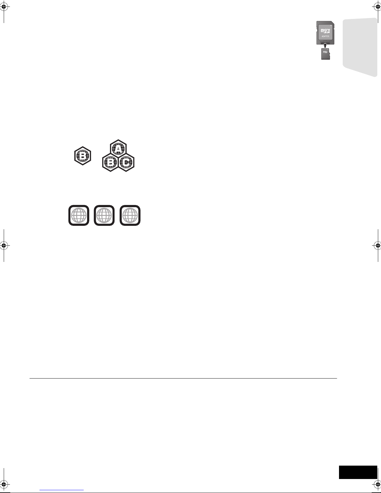
∫ Region management information
BD-Video
This unit plays BD-Video marked with labels containing the
region code B.
Example:
DVD-Video
This unit plays DVD-Video marked with labels containing the
region number “4” or “ALL”.
Example:
∫ SD card
≥ MiniSD Cards, microSD Cards, microSDHC
Cards and microSDXC Cards can be used, but
must be used with an adaptor card. These are
usually supplied with such cards, or otherwise
customer provided.
≥ Keep the Memory Card out of reach of children to
prevent swallowing.
≥ To protect the card’s contents, move the record prevention
tab (on the SD card) to “LOCK”.
≥ This unit is compatible with SD Memory Cards that meet SD
Card Specifications FAT12 and FAT16 formats, as well as
SDHC Memory Cards in FAT32 format (Does not support
long file name.) and SDXC Memory Cards in exFAT.
≥ If the SD card is used with incompatible computers or
devices, recorded contents may be erased due to the card
being formatted etc.
≥ Useable memory may be slightly less than the card capacity.
∫ USB device
≥ This unit supports connecting a USB memory, digital camera
and video camera produced by Panasonic, etc. It is not
warranted that all USB devices will work with this unit.
≥ This unit does not support USB device charging.
≥ FAT12, FAT16 and FAT32 file systems are supported.
≥ This unit supports USB 2.0 High Speed.
Getting started
1
4
ALL
2
4
∫ Finalize
DVD-R/RW/R DL, +R/+RW/+R DL and CD-R/RW recorded by
a recorder, etc. needs to be finalized by the recorder to play on
this unit. Please refer to the recorder’s instructions.
∫ BD-Video
This unit supports high bit rate audio (Dolby Digital Plus, Dolby
TrueHD, DTS-HD High Resolution Audio and DTS-HD Master
Audio) adopted in BD-Video. In order to enjoy these audio
formats, refer to page 38.
∫ Music CD
Operation and sound quality of CDs that do not conform to
CD-DA specifications (copy control CDs, etc.) cannot be
guaranteed.
≥ It may not be possible to play the above media in some cases due to the type of media, the condition of the recording, the recording method and how the files
were created.
≥ The producers of the disc can control how discs are played. So you may not always be able to control play as described in these operating instructions. Read
the disc’s instructions carefully.
VQT2Q55
9
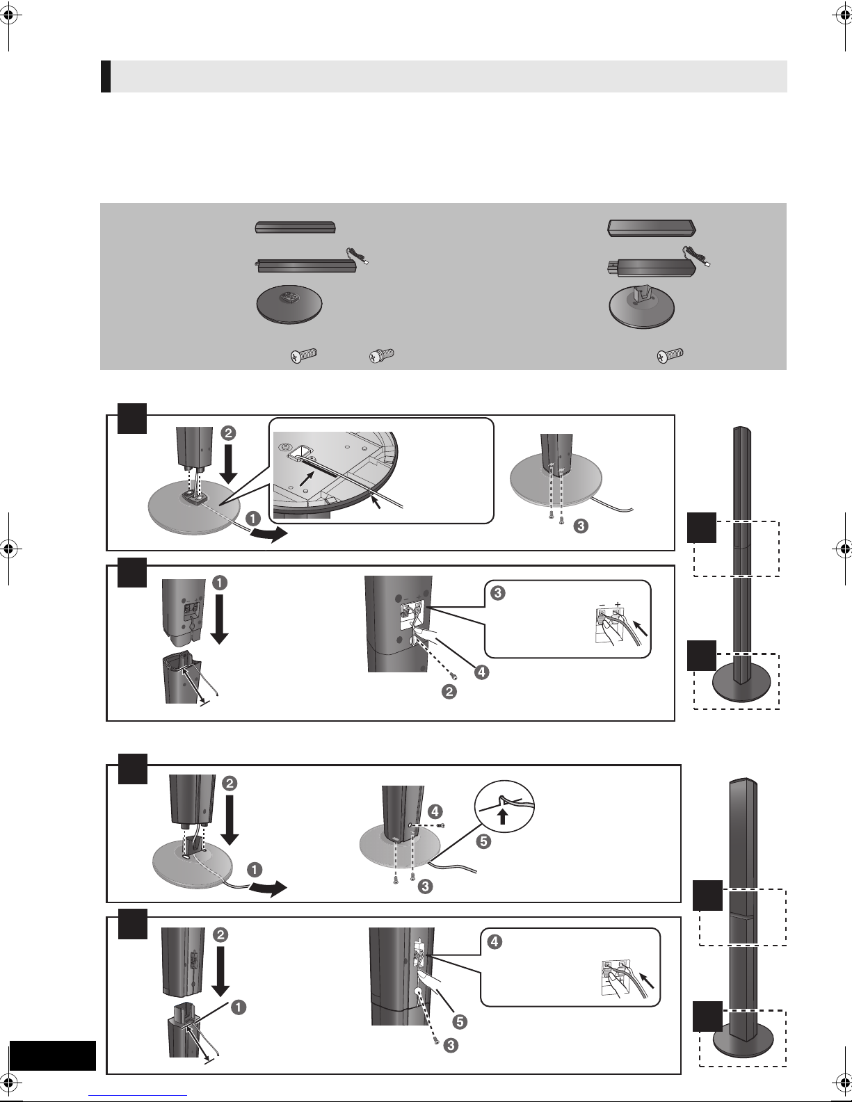
STEP 1: Preparing the speakers
1
2
2
1
Back of the base
Tighten
securely.
Insert the wire fully.
r: White
s: Blue line
Push!
Leave about 80 mm
Tighten securely.
Screw A
Screw B
Press into the groove.
Pull the cable
straight along
the line and
slide into the
groove.
1
2
2
1
Slide into the groove.
Tighten securely.
Insert the wire fully.
r: White
s: Blue line
Push!
Position the cable
between the ridges.
Leave about 120 mm
Press into the groove.
Tighten securely.
Screw
Assembling the speakers
[BT737] [BT337]
Caution
≥ Do not stand on the base. Be cautious when children are
near.
≥ When carrying speakers, hold the stand and base parts.
[BT737]
2 Front speakers
2 Surround speakers
4 Stands (with cables)
4 Bases
8 Screws A
4 Screws B
A B
[BT737]
Preparation
≥ To prevent damage or scratches, lay down a soft cloth and
perform assembly on it.
≥ For wall mount, refer to page 42.
≥ Keep the screws out of reach of children to prevent
swallowing.
[BT337]
2 Front speakers
2 Stands (with cables)
2 Bases
8 Screws
[BT337]
VQT2Q55
10
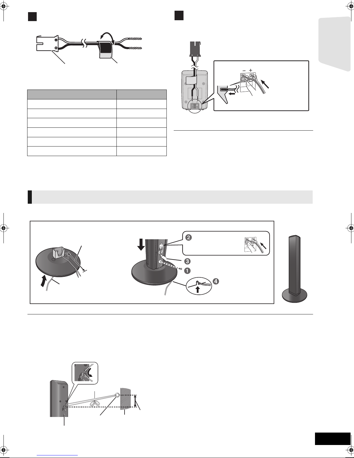
3
Use of the speaker cable stickers is convenient
when making cable connections.
e.g. Front speaker (L)
Push!
r: White
s: Blue line
Connecting the speaker cables. Insert the wire fully,
taking care not to insert beyond the wire insulation.
e.g. Surround speaker [BT230]
Thread the speaker cable
through the base.
Attach the speaker.
Leave about 120 mm
You can remove and use the cable from
the stand. To reattach the cable, refer to
page 42.
Insert the wire fully.
r: White
s: Blue line
Push!
Press into the groove.
Tighten securely.
Slide into the
groove.
FRONT
Lch
A Speaker cable sticker (included)
B Connector
Speaker cable sticker Colour
1 FRONT (L) WHITE
2 FRONT (R) RED
3 SURROUND (L) BLUE
4 SURROUND (R) GREY
5 CENTRE GREEN
6 SUBWOOFER PURPLE
Be sure to match the number on each sticker with the
connector colour.
4
Getting started
≥ Be careful not to cross (short-circuit) or reverse the polarity of the
speaker wires as doing so may damage the speakers.
≥ Don’t use a front speaker as a surround speaker or vice versa. Verify
the type of speaker with the label on the rear of the speaker before
connecting the appropriate cable.
≥ To avoid injury by falling or dropping the speaker, place the speaker cables
with care not to stumble or hook.
≥ Do not hold the speaker in one hand to avoid injury by dropping the
speaker when carrying.
Speaker assembly option
[BT337]
[BT737] [BT337]
∫ Preventing the speakers from falling
≥Consult a qualified housing contractor concerning the appropriate procedure when attaching to a concrete wall or a surface that
may not have strong enough support. Improper attachment may result in damage to the wall or speakers.
≥Use a string of less than ‰ 2.0 mm, which is capable of supporting over 10 kg.
e.g., [BT737]
A String (not included)
Thread from the wall to the speaker and tie tightly.
B Rear of the speaker
C Screw eye (not included)
D Wall
E Approx.150 mm
VQT2Q55
11
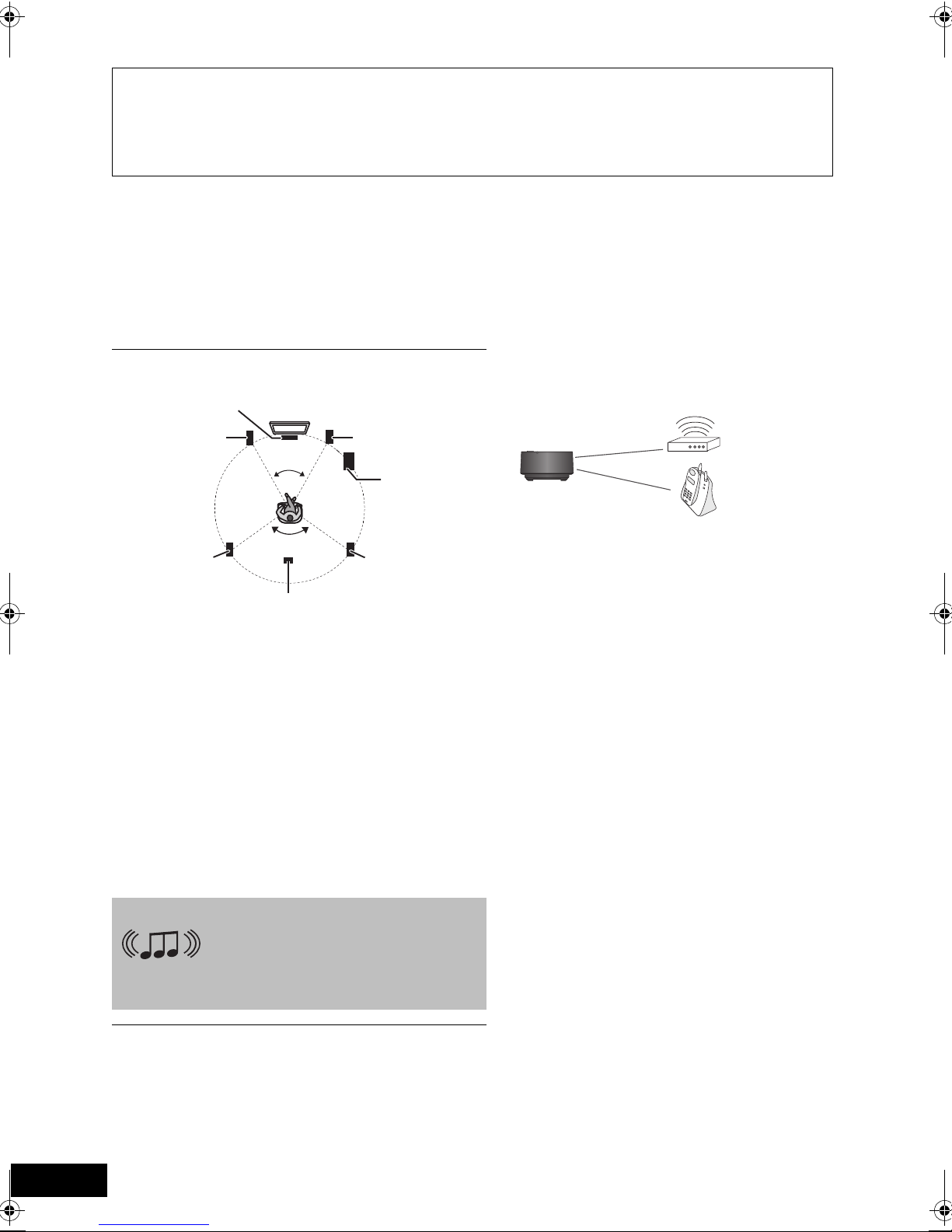
STEP 2: Positioning
120°
60°
e.g.,
Wireless LAN:
approx. 2 m
Cordless phone and
other electronic devices:
approx. 2 m
Wireless
system
Caution
≥ The main unit and supplied speakers are to be used only as indicated in this setup. Failure to do so may
lead to damage to the amplifier and/or the speakers, and may result in the risk of fire. Consult a qualified
service person if damage has occurred or if you experience a sudden change in performance.
Do not attempt to attach these speakers to walls using methods other than those described in this manual.
≥
≥ Do not touch the front netted area of the speakers. Hold by the sides.
How you set up your speakers can affect the bass and the sound field.
Setup example
Place the front, centre, surround speakers at approximately
the same distance from the seating position.
The angles in the diagram are approximate.
[BT337]
[BT737]
Using “Auto Speaker Setup” (> 19) is a convenient way to get
the ideal surround sound from your speakers when you are
unable to place them.
≥
Keep your speakers at least 10 mm away from the system for proper ventilation.
A Centre speaker
Put on a rack or shelf. Vibration caused by the speaker can
disrupt the picture if it is placed directly on the TV.
B Front speakers
C Subwoofer
D Surround speakers
Place the speakers at the same height or higher than ear level.
≥
E [BT737] [BT337] Wireless system
≥ Place the wireless system within approximately 10 m
from the main unit, and in a horizontal position with the
top panel faced upward.
≥ To allow for proper ventilation and to maintain good
airflow around the wireless system, position it with at
least 5 cm of space on all sides.
≥ Do not use the wireless system or the digital transmitter
in a metal cabinet or bookshelf.
[BT230] You can enjoy surround speaker sound
wirelessly when you use the optional
Panasonic wireless accessory
(SH-FX71).
For more details, refer to the operating
instructions for the optional wireless system.
VQT2Q55
≥ Use only supplied speakers
Using other speakers can damage the unit, and sound quality will be
negatively affected.
≥ You can damage your speakers and shorten their useful life if you play
sound at high levels over extended periods.
≥ Positioning speakers in front
It is possible to locate all the speakers in front of the listening position.
However, the optimal surround sound effect may not be obtainable.
≥ Place speakers on flat secure bases.
≥ Placing speakers too close to floors, walls, and corners can result in
12
excessive bass. Cover walls and windows with thick curtains.
≥ For optional wall mount, refer to page 42.
∫ If irregular colouring occurs on your TV,
turn the TV off for about 30 minutes.
If it persists, move the speakers further away from the TV.
[BT737]
[BT337]
∫ Wireless system
To avoid interference, maintain the following distances
between the wireless system and other electronic devices
that use the same radio frequency (2.4 GHz band).
The wireless system will automatically seek a clear channel if
any of these other devices interfere with its communication.
When this happens, the wireless link indicator (“ [W] ”) flashes
on the main unit, and there is a brief interruption in audio
coming from the surround speakers.
This is the normal operation of the product working to assure
the best possible performance of your home theatre system.
If the interference persists, try moving the other devices to
another location outside the range of the wireless system or
move the wireless system nearer to the main unit.
∫ Upgrade your system to 7.1-channel
system
The main unit is designed to enjoy the 7.1ch surround sound.
By connecting 2 units of the Panasonic wireless system
SH-FX71 with 4 speakers, more theatre-like effect can be
available.
Necessary equipment:
[BT337]
[BT737]
≥ 1 optional wireless system (SH-FX71)
≥ 2 additional speakers
[Impedance: 3 ≠ to 6 ≠, Speaker input power: 100 W (Min)]
[BT230]
≥ 2 optional wireless systems (SH-FX71)
≥ 2 additional speakers
[Impedance: 3 ≠ to 6 ≠, Speaker input power: 100 W (Min)]
For more details, refer to the operating instructions for the
optional wireless system.
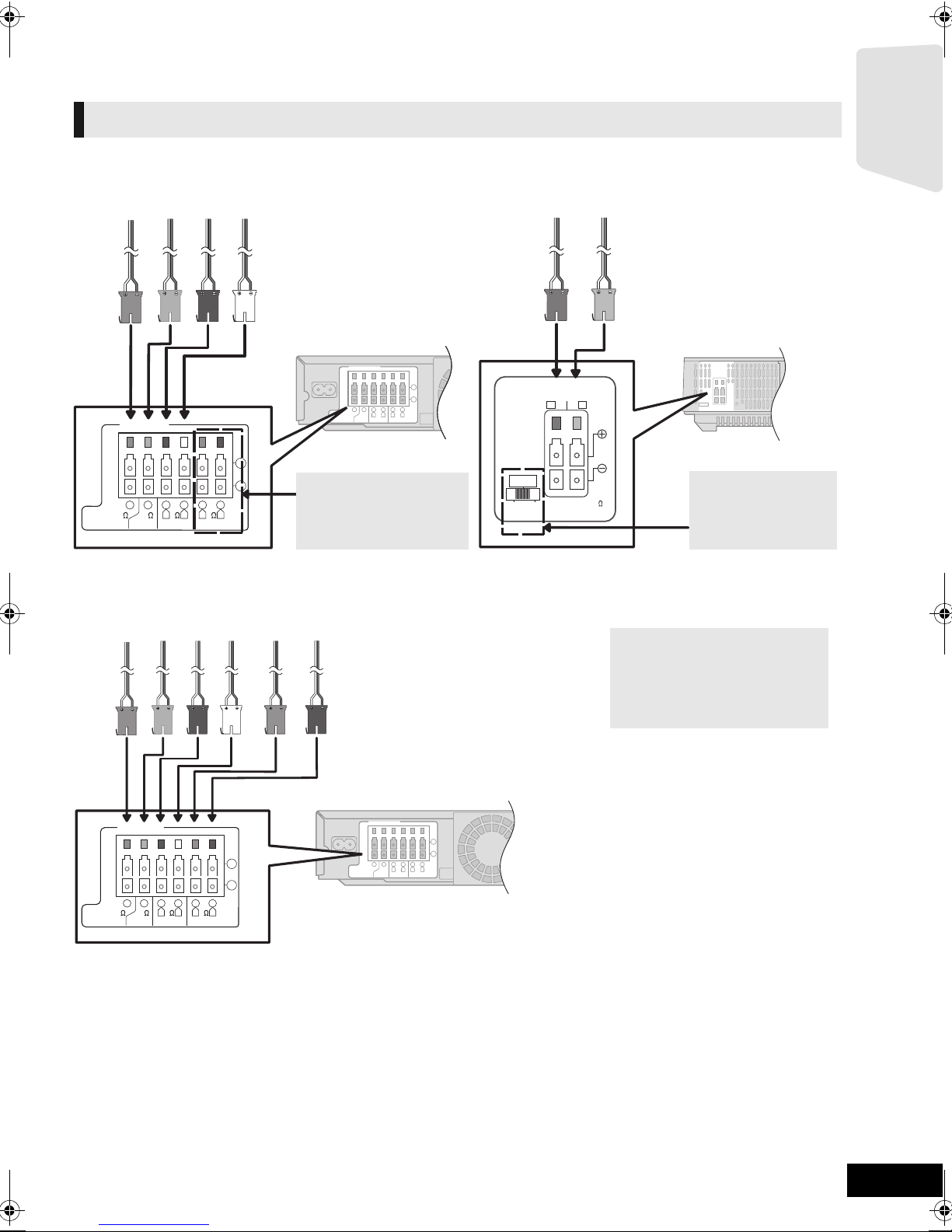
STEP 3: Connections
Main unit
Surround selector
The surround selector
switch must be set in
the centre position.
6 PURPLE Subwoofer
5 GREEN Centre speaker
2 RED Front speaker (Rch)
1 WHITE Front speaker (Lch)
Wireless system
3 BLUE Surround speaker (Lch)
4 GREY Surround speaker (Rch)
Do not connect the
surround speaker cables
to the main unit when
using the wireless system.
Main unit
6 PURPLE Subwoofer
5 GREEN Centre speaker
2 RED Front speaker (Rch)
1 WHITE Front speaker (Lch)
4 GREY Surround speaker (Rch)
3 BLUE Surround speaker (Lch)
When using the optional wireless
system, do not attempt to connect
any extra surround or surround
back speakers to the main unit.
Turn off all equipment before connection and read the appropriate operating instructions.
Do not connect the AC mains lead until all other connections are complete.
Speaker cable connection
Connect to the terminals of the same colour.
[BT737]
[BT337]
4
2
6
5
R L
366
FRONT
CENTERSUBWOOFER
1
R L
3
SURROUND
3
[BT230]
SURR
L
SIDERSIDE
SPEAKERS
ENCEINTES
LS / RB LB / RS
SURROUND (3 - 6
AMBIOPHONIQUES
)
Getting started
6
2
1
5
R L
366
FRONT
CENTERSUBWOOFER
4
3
R L
3
SURROUND
VQT2Q55
13
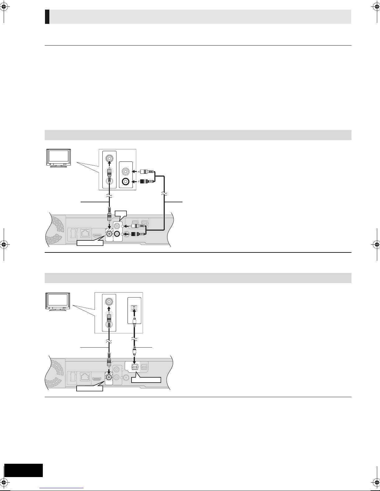
Connection to a TV
AV
OUT
VIDEO
OUT
AUX
L
R
VIDEO
OUT
L
R
AUX
L
VIDEO IN
R
AUDIO IN
L
R
AUD I O O UT
VIDEO OUT
AUX
TV
A Video cable (included)
B Audio cable (not included)
AUX
1
LRL
R
2
OPTICAL
1
DIGITAL AUDIO IN
VIDEO
OUT
VIDEO
OUT
OPTICAL
OUT
L
VIDEO IN
R
AUDIO IN
OPTICAL 1
VIDEO OUT
TV
A Video cable (included)
B Optical digital audio cable
(not included)
The basic connection is shown in the included Easy Setting Guide, however, there are more connection examples to optimize
your system setting.
≥ Do not make the video connections through the VCR.
Due to copy guard protection, the picture may not be displayed properly.
≥Turn off all equipment before connection.
∫ OPTICAL IN
≥ After making the digital audio connection, make settings to
suit the type of audio from your digital equipment (> 30).
∫ HDMI
The HDMI connection supports VIERA Link “HDAVI Control”
(> 31) when used with a compatible Panasonic TV.
Basic connection
≥ Please use High Speed HDMI Cables that have the HDMI
logo (as shown on the cover). It is recommended that you
use Panasonic’s HDMI cable. When outputting 1080p signal,
please use HDMI cables 5.0 meters or less.
Recommended part number:
RP-CDHS15 (1.5 m), RP-CDHS30 (3.0 m),
RP-CDHS50 (5.0 m), etc.
≥To enjoy TV audio from this home theatre system’s speakers, select “AUX (TV)” as a source (> 23).
Connection for the better audio
≥To enjoy TV audio from this home theatre system’s speakers, select “DIGITAL IN 1 (TV)” or “D-IN 1” as a source.
VQT2Q55
14
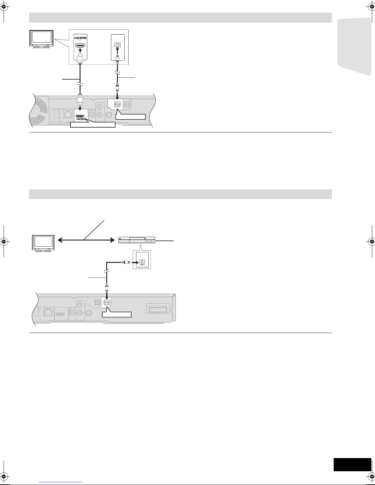
Connection for the best picture and audio
VIDEO
OUT
AUX
OPTICAL
21
DIGITAL AUDIO IN
L
R
OPTICAL
21
DIGITAL AUDIO IN
L
R
2
OPTICAL
1
DIGITAL AUDIO IN
AV
OUT
AV
OUT
(ARC)
OPTICAL
OUT
AV IN
OPTICAL 1
HDMI AV OUT (ARC)
TV
A HDMI cable (not included)
B Optical digital audio cable (not included)
≥ For the TV audio, an audio cable (not included) can be also
used by connecting the AUX terminal with the AUDIO OUT
terminal on the TV.
LAN
AUX
LAN
DIGITAL TRANSMITTER
LRL
R
OPTICAL
21
DIGITAL AUDIO IN
OPTICAL
1
DIGITAL AUDIO IN
OPTICAL
OUT
OPTICAL 2
TV
A Optical digital audio cable (not included)
B Set Top Box, cable TV, VCR, DVD recorder, etc.
Refer to the operating instructions of the respective
devices for the optimal connections.
≥To enjoy TV audio from this home theatre system’s speakers, select “DIGITAL IN 1 (TV)” or “D-IN 1” as a source (> 23).
ARC (Audio Return Channel)
(Available when using an ARC compatible TV)
With this function it is possible to receive the digital audio signal from the TV without connecting any other audio cables.
≥Select “ARC (TV)” as the audio input source (> 23)
≥Refer to the operating instructions of the TV for the settings to output digital audio.
Connection with Set Top Box, etc.
Getting started
≥To enjoy TV audio from this home theatre system’s speakers, select “DIGITAL IN 2 (CABLE/SAT)” or “D-IN 2” as a source
(> 23).
NECESSARY SETTINGS
≥ “HDMI Audio Output” : “Off” (> 39)
VQT2Q55
15
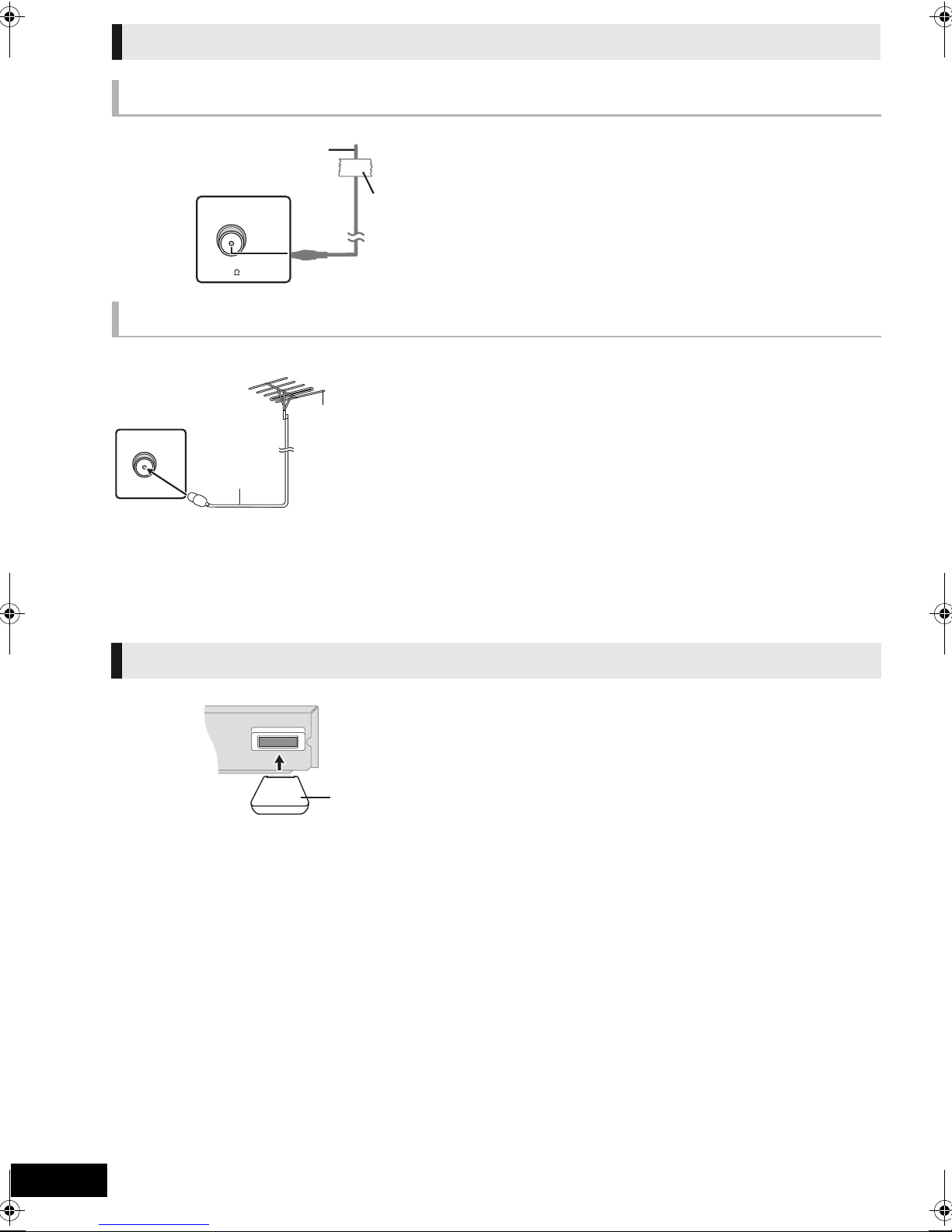
Radio antenna connection
Main unit
A FM indoor antenna (included)
B Adhesive tape
Affix this end of the antenna where reception is best.
FM ANT
Ω
(
75
)
Main unit
A FM outdoor antenna [Using a TV antenna
(not included)]
The antenna should be installed by a competent technician.
B 75 ≠ coaxial cable (not included)
e.g.,
DIGITAL TRANSMITTER
Insert fully until you hear a click.
Do not insert or remove while the
home theatre unit is on.
Using an indoor antenna
FM ANT
(75 )
Using an outdoor antenna
Use outdoor antenna if FM radio reception is poor.
[BT737] [BT337] Digital transmitter connection
VQT2Q55
16
 Loading...