

Page 1
Operating Instructions
For Canada only: The word “Participant” is used in place of the word
“Partner”.
As an ENERGY
[For[the[U.S.A.[and[Canada[
STAR Partner,
Panasonic has determined that
this product meets the ENERGY STAR
guidelines for energy efficiency.
®
®
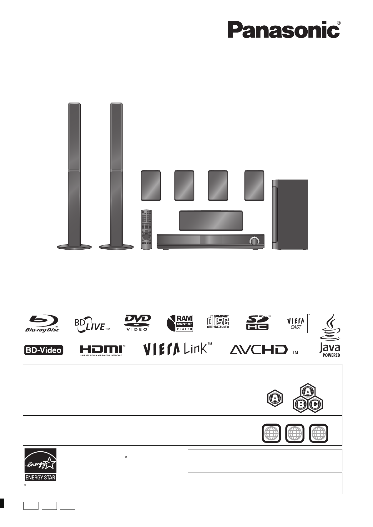
Blu-ray Disc Home Theater Sound System
Model No. SC-BT303
SC-BT300
SC-BT203
SC-BT200
The illustration shows the image of the unit SC-BT300 with “P” indicated on the packaging.
Dear customer
Thank you for purchasing this product.
For optimum performance and safety, please read these instructions carefully.
Before connecting, operating or adjusting this product, please read the instructions completely. Please keep this manual for future reference.
To update the firmware of this unit, refer to page 32.
Region m anagement information
BD-Video
This unit plays BD-Video marked with labels containing the region code A.
DVD-Video
This unit plays DVD-Video marked with labels containing the region number “1” or “ALL”.
Example:
Example:
1
ALL
1
2
4
P PC
PX
If you have any questions contact
[U.S.A.]and]Puerto]Rico]:1 -800-211-PANA(7262)
[Canada]: 1-800-561-5505
[Only]for[U.S.A.]and]Puerto]Rico]:
The warranty can be found on page 58.
[Canada]: The warranty can be found on page 59.
RQT9508-1P
Page 2
Getting started
≥
These operating instructions are appli cable
to models SC-BT300, SC-BT303, SC-BT200
and SC-BT203 for a variety of regions. Unless
other w ise indica te d, illu s tr ati on s in thes e
operating instructions are of SC -BT300.
≥
Please note that the actual controls and
components, menu items, etc. of your Blu-ray
Disc Home Theater Sound System may look
some wh at differen t from tho se sh ow n in the
illustr ation s in the s e Operatin g Inst ructions.
≥Operations in these instructions are
described mainly with the remote control,
but you can perform the operations on the
main unit if the controls are the same.
Indicates features applicable to:
\BT300\
: SC-BT300 only
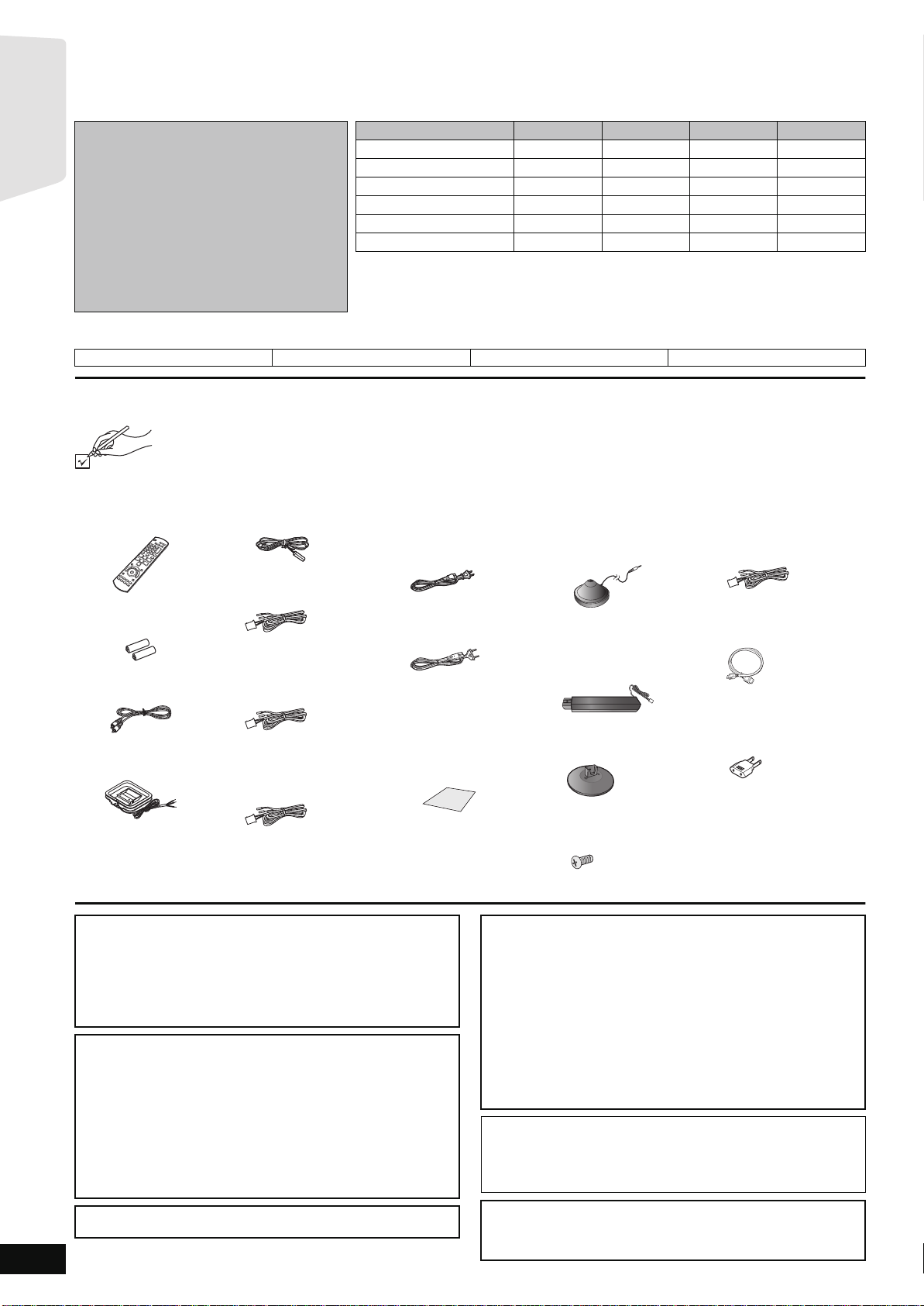
Accessories
Please check and identify the supplied accessories. Use numbers indicated in parentheses when asking for replacement par ts.
(Product numbers correct as of June 20 09. These may be subject to chan ge.)
Only for U.S.A . and Puer to Rico: To order accessories, refer to “Accessory Purchases (United States and Puerto Rico)”
on page 58.
For other areas: To order accessor ies, call the dealer from whom you have made your purcha se.
∏ 1 Remote contr ol
(N2QAKB000072)
∏ 2 Remote contr ol
batteries
∏ 1 Video cable
(K2KA2BA00001)
∏ 1 AM loop antenna
(N1DAAAA00002)
System SC-BT300 SC-BT303 SC-BT200 SC-BT203
Main unit SA-BT300 SA-BT300 SA-BT200 SA-BT203
Front speakers SB-HF770 SB-HF770 SB-HF470 SB-HF470
Center speaker SB-HC300 SB-HC300 SB-HC200 SB-HC200
Surround speakers SB-HS470 SB-HS470 SB-HS470 SB-HS470
Surround back speakers SB-HS470 SB-HS470 SB-HS470 SB-HS470
Subwoofer SB-HW200 SB-HW200 SB-HW200 SB-HW200
≥Som e mode ls ma y not be on sale in certain regio ns .
≥Some accessories and external devices mentioned in these operating instructions
\BT303\
: SC-BT303 only
∏ 1 FM indoor antenna
(RSAX0002)
∏ 1 Speaker cable (center)
[REEX0858-L (green)]
∏ 2 Speaker cables
(surround)
[REEX0860E-L (blue)]
[REEX0868E-L (gray)]
∏ 2 Speaker cables
(surround back)
[REE1488 (brown)]
[REE1489 (tan)]
that are not included with this product may not be on sale in certain regions.
SC-BT200 only
[BT200]:
∏ 1 AC power supply
cord
[For[the[U.S.A.[and[Canada[[
(K2CB2CB00021)
[For[units[with[PX[printed[
[on[the[packaging[
(K2CQ2CA00007)
≥For use with this unit only.
Do not use it with other
equipme nt. Also, do not
use cords from other
equipment with this unit.
∏ 1 Sheet of speaker
cable stickers
[BT300] [BT303] [BT200]
∏ 1 Auto speaker setup
microphone
(L0CBAY000034)
[BT300] [BT303]
∏ 2 Speaker stands
(with cable)
[RYPX0386-KLJ (white)]
[RYPX0386-KRJ (red)]
[BT300] [BT303]
∏ 2 Bases
(RYPX0389-KJ)
[BT300] \BT303\
∏ 8Screws
(XTN5r10FFJK)
SC-BT203 only
[BT203]:
[BT200] [BT203]
∏ 2 S pe ak er ca bl e s (f ro n t)
[REEX0859-L (white)]
[REEX0867A-L (red)]
\BT303\
∏ 1 HDMI cable
(K1HA19DA0005)
∏ 1 Power plug adapt or
[For[units[with[PX[printed[
[on[the[packaging[
(K2DAYYY00002)
RQT9508
2
(ONLY FOR CANADA) The enclosed Canadian French label sticker corresponds to the English display on the front and back side of the unit.
CAUTION!
THIS PRODUCT UTILIZES A LASER.
USE OF CONTROLS OR ADJUSTMENTS OR PERFORMANCE
OF PROCEDURES OTHER THAN THOSE SPECIFIED HEREIN
MAY RESULT IN HAZARDOUS RADIATION EXPOSURE.
DO NOT OPEN COVERS AND DO NOT REPAIR YOURSELF.
REFER SERVICING TO QUALIFIED PERSONNEL.
WARNING:
TO REDUCE THE RISK OF FIRE, ELECTRIC SHOCK OR
PRODUCT DAMAGE,
≥DO NOT EXPOSE THIS APPARATUS TO RAIN, MOISTURE,
DRIPPING OR SPLASHING AND THAT NO OBJECT S FIL LED
WITH LIQUIDS, SUCH AS VASES, SHALL BE PLACED ON
THE APPARATUS.
≥USE ONLY THE RECOMMENDED ACCESSORIES.
≥DO NOT REMOVE THE COVER (OR BACK); THERE ARE NO
USER SERVICEABLE PARTS INSIDE. REFER SERVI CING TO
QUALIFIED SERVICE PERSONNEL.
[For[units[with[PX[printed[on[the[packaging[
THIS UNIT IS INTENDED FOR USE IN MODERATE CLIMATES.
CAUTION!
≥DO NOT INSTALL OR PLACE THIS UNIT IN A BOOKCASE,
BUILT-IN CABINET OR IN ANOTHER CONFINED SPACE.
ENSURE THE UNIT IS WELL VENTILATED. TO PREVENT
RISK OF ELECTRIC SHOCK OR FIRE HAZARD DUE TO
OVERHEAT ING, ENSURE THA T CURTAINS AND ANY OTHER
MATERIALS DO NOT OBSTRUCT THE VENTILATION VENTS.
≥DO NOT OBSTRUCT THE UNIT’S VENTILATION OPENINGS
WITH NEWSPAPERS, TABLECLOTHS, CURTAINS, AND
SIMILAR ITEMS.
≥DO NOT PLACE SOURCES OF NAKED FLAMES, SUCH AS
LIGHTED CANDLES, ON THE UNIT.
≥DISPOSE OF BATTERIES IN AN ENVIRONMENTALLY
FRIENDLY MANNER.
The socket outlet shall be installed near the equ ipment and easily
accessible.
The mains plug of the power supply cord shall remain readily
operable. To c ompletely disconnect th is apparatus from the AC
Mains, disconnect the power supply cord plug from AC receptacle.
[For[units[with[PX[printed[on[the[packaging[
This product ma y receive r adio interferen ce caused by mobile
telephones during use . If such interference is apparent, please
increase separation between the product and the mobile telephone.
Page 3
Getting started
THE FOLLOWI NG APPLIES ONLY IN THE U.S.A.
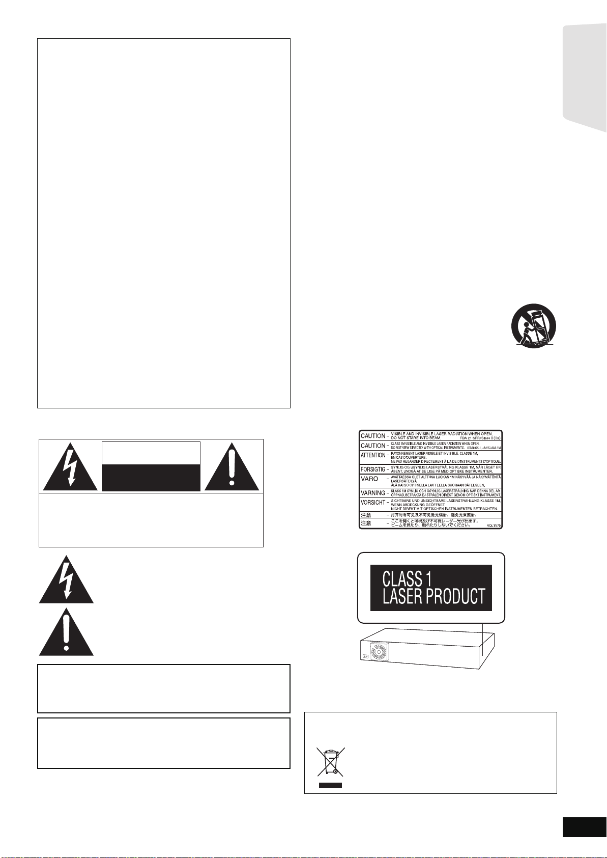
The lightning flash with arrowhead symbol, within
an equilateral triangle, is intended to alert the user
to the presence of uninsulated “dangerous
voltage” within the product’s enclosure that may be
of sufficient magnitude to constitute a risk of
electric shock to persons.
CAUTION
CAUTION: TO REDUCE THE RISK OF ELECTRIC
SHOCK, DO NOT REMOVE SCREWS .
NO USER-SERVICEABLE PARTS
INSIDE.
REFER SERVICING TO Q UALIFIED
SERVICE PERSONNEL.
The exclamation point within an equilateral triangle
is intended to alert the user to the presence of
important operating and maintenance (servicing)
instructions in the literature accompanying the
appliance.
RISK OF ELECTRIC SHOCK
DO NOT OPEN
FCC Note:
This eq uipm en t ha s bee n t e sted an d f oun d t o co mply w i th t h e l im it s
for a Class B digital device, pursuant to Part 15 of the F CC Rules.
These limits are d esigned to provide reasonabl e prot ection against
harmful inter ference i n a residential i nstallation. This equipment
generat es , uses , a nd ca n ra di at e r ad io fr eq uen cy ener g y a nd , if n ot
installed and used in accordance with the instructions, may cause
harmful interfe rence to radio communications.
However, there is no guarantee that interference will not occur in a
particular installation. If this equipment does cause harmful
interference to radio or television reception, which can be
determined by turning the equipment off and on, the user is
encouraged to try to correct the interference by one or more of the
following measu res:
≥Reorient or relocate the receiving antenna.
≥Increase the separation b etween the equipment and r eceiver.
≥Connect the equipment into an outlet on a circuit different from
that to which the receiver is conn ected.
≥Co ns ult the deal er or an ex pe ri e n ce d r ad io /TV tec h nician fo r
help.
FCC Ca uti on:To assure continued compliance, follo w the att a ch ed
installation instructions and use only shield ed interface cables
when connecting to peripheral devices. Any changes or
modif ic ations not ex pre s sly appro ve d by the par t y r es po ns ible for
compliance could void the user’s authority to operate this
equipment.
This device complies with Part 15 of the FCC Rules.
Operation is subject to the following two conditions:
(1) This device may not cau s e harmful interference, and
(2) this device must accept any interference received, including
interference that may cause undesired op eration.
Responsible Party:
Panasonic Corpor ation of North America
One Pan as o nic Way
Secaucus, NJ 07094
Support Contact:
Panasonic Consumer Electronics Company
Telephone No.: 1-800-211-PANA (7262)
IMPORTANT SAFETY INSTRUCTIONS
Read these opera tin g in structio ns ca ref u ll y be f o re us ing the unit .
Follow the safety instructions on the unit and the applicable safety
instructions listed below . Keep these operating in structi ons handy for
future reference.
1) Read these instructions.
2) Keep these instructions.
3) Heed all warnings.
4) Follow all instru ct ions.
5) Do not use this appara tu s ne ar w ate r.
6) Clean only with dry cloth.
7) Do not block any ventilation openings. Install in accordance with
the manu f a ct ur e r’s inst ruc tions.
8) Do not install near any heat sources such as radiators, heat
registers, stoves, or other apparatus (including amplifiers) that
produc e he at.
9) [For[the[U.S.A.[and[Canada[
Do not defeat the safety purpose of the polarized or grounding-type
plug. A polarized plug has two blades with one wider than the other.
A groundi n g-t ype pl ug has tw o blade s an d a th ird gr ou ndin g pr on g.
The wide bl ad e or th e thi r d p ron g a re pr o vi de d for y our s af et y. If the
provided plug does not fit into your outlet, consult an el ectrician for
replac em e nt of th e obs o lete outlet .
10)Pr otect the power cor d from being walked on or pinched
particularly at plugs, convenience receptacles, and the point where
they exit from the apparatus.
11)Only use attachments/accessories specified by the manufacturer.
12)Use only with the cart, stand, tripod, bracket, or table
specif ied by the manufacturer, or sold with the
apparatus. Wh en a cart is used, use caution when
moving the cart/apparatus combination to avoid injury
from tip-over.
13)Unplug this apparatus during lightning storms or when
unused for long periods of time.
14)Ref er all servicin g to qualified service personnel. Servicing is
required when th e apparatus has been damaged in any way, such
as power-supply cord or plug is damaged, liquid has been spilled or
objects have fallen into the apparatus, the apparatus has been
exposed to rain or moisture, does n ot operate normally, or has
been dropped.
THE FOLLOWING APPLIES ONLY TO THE U.S.A. AND CANADA.
CAUTION
Danger of explosion if battery is incorr ectly replaced. Replace only
with the same or equivalent type recommended by the manufacturer.
Dispose of used batteries according to the manufacturer’s
instructions.
[For[units[with[PX[printed[on[the[packaging[
CAUTION:
The AC voltage is di fferent according to th e area. Be sure to set
the proper voltage in your area before use.
(For details, please refer to page 14.)
(Inside of pro duct)
The laser product label has not been attached to products for the
U.S.A. and Canada.
-If you see this symbolInformation on Disposal in other Countries outside the
European Union
This s y mbol is only valid in the European Union.
If you w is h to di sc ard th is pro du ct , pl ea se co nta ct y our
local authori ties or de aler and ask for the correct
method of disposal.
RQT9508
3
Page 4

Getting started TV Radio PlaybackOther devices
Advanced operations
Reference Optional speaker
settings
Table of contents
Getting started
Accessories......... ...............................................2
IMPORTANT SAFETY INSTRUCTIONS ............3
Control reference guide (rem ote con trol)........5
Preparing the r emot e contr ol............ ................5
Batteries ................................................................. 5
Use ......................................................................... 5
Control reference guide (main unit).................6
Front panel .................... ...................... ...................6
Rear pan e l te r m in a ls ........... .......... ................. ........ 6
Assembling the speakers...............................7
Positioning......................................................8
Speaker connections...................................... 9
TV connections.......... ........................ ...........10
Connections with a video cable...............................10
Connections with a component video cable...........11
Connections with an HDMI cable.............................11
Connections to a Set Top Box, etc..............12
Radio antenna connections.........................13
Broadband Network Connections...............14
AC power supply cord conn ection..............14
SMART SETUP / EASY SETUP....................15
Basic settings for the system ... .... ............... ............ 1 5
Showing START menu ................................ ....16
Selecting the playback source .......................17
Selecting the source from the START menu........17
Selecting the source wi th the remote control........17
Enjoying sound from all speakers
and various sound effe c ts..... .......................18
Enjoying surrou nd sound effects.. .. .. ....................18
Changing the sound modes..................................18
Adjusting speaker level during play......................18
Playback
Basic operations..............................................19
Other operations duri ng play................. ...............20
Playing video recorded on a Video Camera or
Video Recorder.... .. ...................... ......................21
Enjoying BD-LIVE or BONUSVIEW
in BD-Video.... ....................... ..........................22
Playing secondary video (picture-in-picture)
and secondary audio. .........................................22
Enjoyi n g BD - L iv e d is cs with In te rnet .... .. ... ........... 22
Playing still pictures........................................23
Useful functions during still picture play...............24
Playing music...................................................25
TV
Enjoying TV, etc. with
this unit’s speakers .......................................27
Enjoying TV and other devices sound
from this unit’s speakers..................................... 27
Adjusting the sound..............................................27
Making settings for digital audio input..................27
Linked operations with the TV .......................28
What is VIERA Link “HDAVI Control”? ................. 28
What you can do with “HDAVI Control” ................ 28
Easy control only with VIERA remote control ....... 29
Other devices
Using the iPod .................................................30
iPod Connection....................... ............ ................30
iPod Playback....................................................... 31
Advanced operations
Enjoying VIERA CASTTM..................................32
Firmware updating ..........................................32
Network settings..............................................33
Changing settings with
the on-screen menu ........ ..............................35
On-screen menu operations................. ................35
What you can change with
the on-screen menu ........................................... 35
Changing the unit ’s settings... ................. ......37
Setup menu operatio ns............................. ...........37
Summary of settings............................................. 37
Speake r se t tin g s.......... .......... .......... ................. ....41
Disc and card inf orma t ion ....... ................. ......42
Packaged discs ....................................................42
Record ed di sc s.......... .. .......... ................. .............. 42
SD cards............................................................... 43
Regarding 24p output........................................... 43
Discs that cannot be played .................................43
Disc and card handling................. ..................43
Maintenance..................................................... 43
To dispose or trans f e r this uni t.... ..................43
About MP3/JPEG files.....................................44
Optional speaker settings
Wireless connections (optional) ....................45
Connecting the spea kers with the optional
wireless system (SH-FX70: 2 units) ...................45
Speaker installation options...........................46
RQT9508
Listening to the Radio .....................................26
Setting up the radio .............................................. 26
Listening/confirming the preset channels.............26
4
Radio
Reference
Troubleshooting guide....................................47
Messages .........................................................51
Frequently a ske d questions.......................... .52
Language code list..........................................53
Licenses...........................................................53
Glossary...........................................................54
Specifications..................................................56
Limi ted Warranty
(Only for U.S.A. and Puerto Rico) ................58
Limited Warranty (ONLY FOR CANADA).......59
Product Service...............................................59
Index ..................................................Back co ver
Page 5
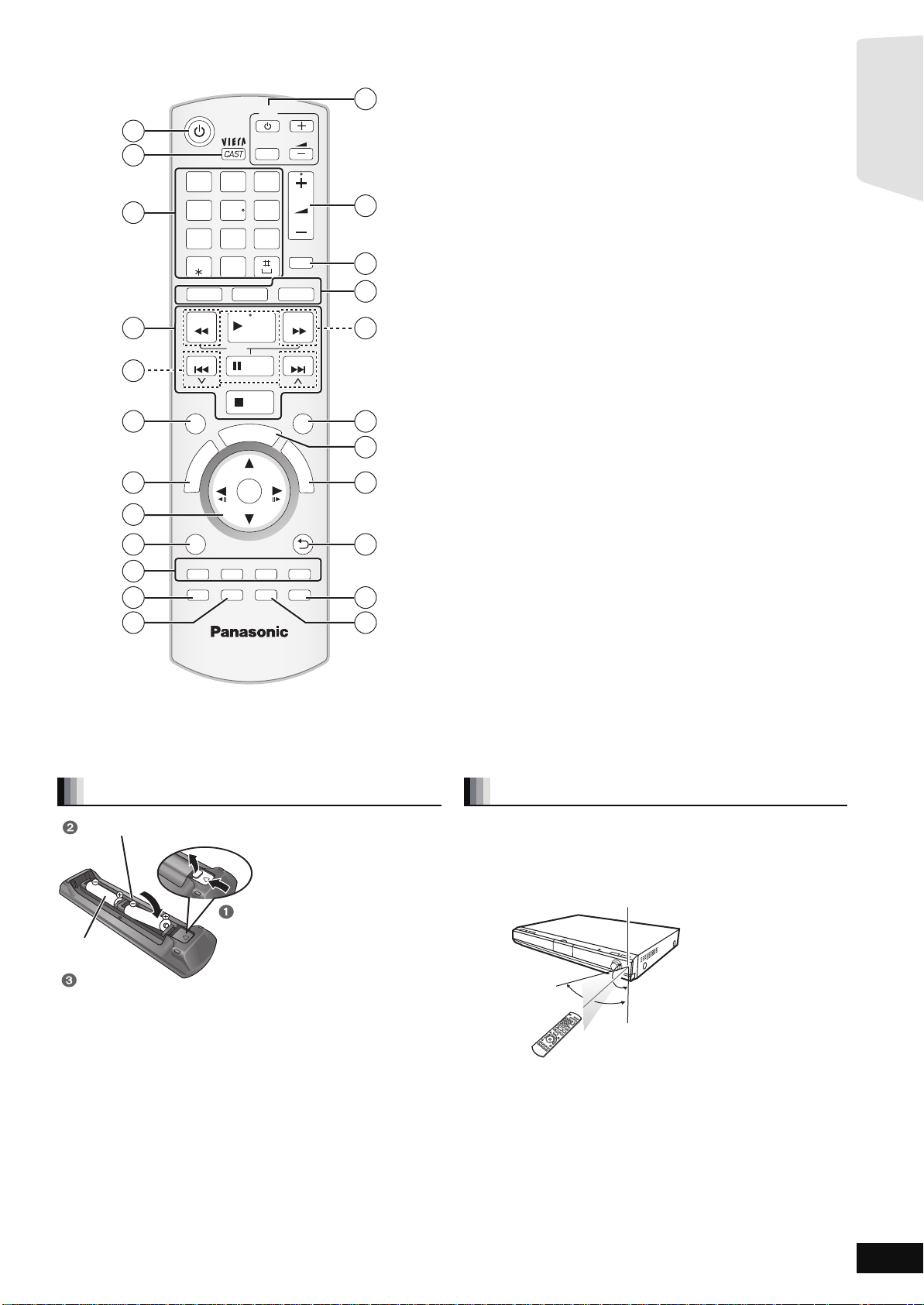
Control reference guide (remote control)
R6/LR6, AA
Insert so the poles ( and ) match those in the remote control.
Press in and lift up.
Replace the lid.
When closing the lid, insert it from the (minus) side.
Remote control signal sen s or
7 m (23 ft.) directly in front of the unit
Getting started
1
2
3
4
5
6
7
8
9
10
11
12
1@.2 3
CANCEL
SURROUND
N
T
C
E
R
I
D
SUB MENU
SETUP
-
CH SELECT
ABC
4 5 6
GHI
JKL
P
7 809
TUV
QRS
_,
BD/SD
SEARCH
SLOW
SKIP
S
R
O
T
A
U
G
I
N
V
A
E
M
P
O
T
RsG
STATUS
iPod
PLAY
PAU SE
STOP
A
T
OK
TV
INPUT
R
T
B
DISPLAY
-
SLEEP
DEF
MNO
W
XYZ
VOL
VOL
MUTE
RADIO
EXT-IN
SEARCH
SKIP
SOUND
P
O
P
-
U
P
M
E
N
U
RETURN
Y
AUDIO
13
14
15
16
17
18
19
20
21
22
23
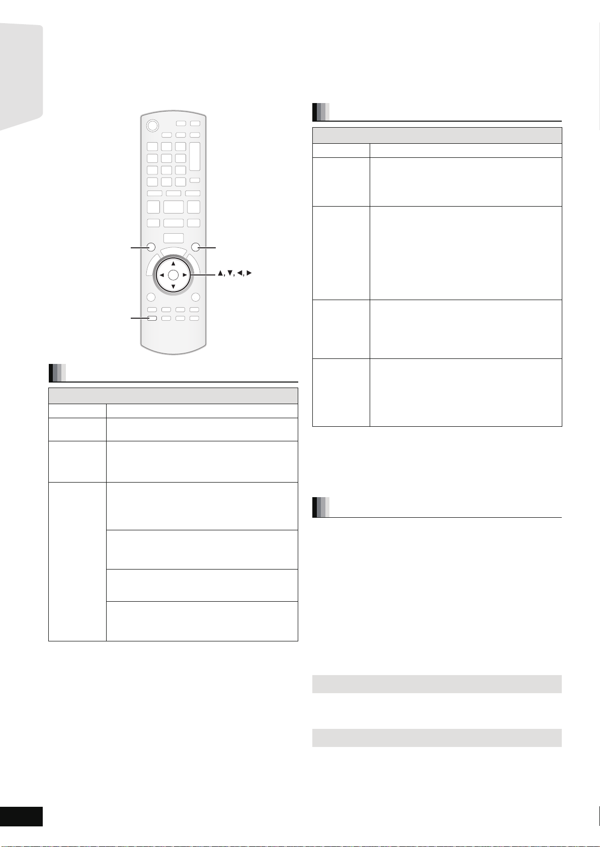
1 Turn the unit on and off (> 19)
2 Display the Home screen of VIERA CAST (> 32)
3 Select t itle numbers, etc. /Enter numbers or characters (> 20, 34)
(The character buttons may be used when operating VIERA CAST
contents. B 32)
[CANCEL] : Cancel
4 Basic playback control buttons (> 19, 20)
5 Select preset radio stations (> 26)
6 Select surroun d sound effe cts (> 18)
7 Show Top Menu/Di r ec t N av ig ato r (> 19)
8 [3, 4, 2, 1]: Menu selection
[OK]: Selection
[2, 1]: Select preset radio station (> 26)
[2] (2;), [1] (;1): Frame-by-frame (> 20)
9 Show su b me nu (> 20)
: These buttons are used when;
≥Operating a BD-Video disc tha t includes Java
(BD-J). For more information about operating this kind of disc,
please read the instructions that came with the disc.
TM
applic ati on s
≥Displaying “Title View” and “Album View” screens. (Only the [R]
and [G] but tons, B 23)
≥Operating contents of VIERA CAST. (> 32)
; Show Setup menu (> 37)/Select speaker channel (> 18)
< Show status messages (> 21)
= TV operation buttons
You can operate the TV through the unit’s remote control.
[Í]: Turn the TV on and off
[INPUT]: Switch the input channel
[ijVOL]: Adjust the TV volume
This may not work properly with some models.
> Adjust the volume of the main unit (> 19)
? Mute the sound (> 19)
@ Select th e so ur ce
[BD/SD]: Select disc drive or SD card drive (> 17)
[iPod]: Select iPod as the source (> 17, 30)
[RADIO/EXT-IN]: Select FM/AM tuner or external audio as
the source (> 17, 26, 27)
A Select radio stations manually (> 26)
B Set the so und mode (> 18)
C Show Start menu (> 16)
D Show po p-up menu (> 19)
E Return to previous screen
F Select audio (> 20)
G Show on-screen menu (> 35) / Se t th e sl ee p t im er (> 21)
Preparing the remote control
Batteries
Aim at the remote control signal sensor (> 6), avoiding obstacles, at a
maximum range of 7 m (23 ft) directly in front of the unit.
≥If you cannot operate the unit or other equipment using the remote
control after changing the batteries, please re-enter the codes
(> 50).
≥Us e alk aline or ma ng an es e bat te r ie s .
≥Do not mix old an d new batteries.
≥Do not use different types at the same time.
≥Do not heat or expose to flame.
≥Do not leave the battery(ies ) in an aut omobile exposed to direct
sunli ght for a long period of time with doors and windows closed.
≥Do not take apart or short circuit.
≥Do not atte m pt to rec harge alk a lin e or ma ng an es e ba tte r ie s .
≥Do not use batteries if the covering has been peeled off.
Mishandling of batteries can cause electrolyte leakage which can
severely damage the remote control.
Remove the batteries if the remote control is not going to be used for a
long period of time. Store in a cool, dar k place.
The distance and the angles are approximate.
Use
30˚
20˚
20˚
30˚
RQT9508
5
Page 6
Getting started
Control reference guide (main unit)
SPEAKERS
FM ANT ANT
EXT
LOOP
AM
75Ω
CENTER
3
Ω
3Ω3
Ω
WOOFER
SUB-
FRONT
GNDANTLOOP
3
Ω
SURROUND
3
Ω
SURROUND BACK
AC IN
6
5
21438
7
RLRLR
L
L
R
AUX(TV)
TRANSMITTER
DIGITAL
AV OU T
)
(
COMPONENT
VIDEO OUT
VIDEO
OUT
Y
P
R
PB
OPTICAL
2(STB) 1(TV)
DIGITAL IN
+
-
110
127V
220
240V
TRANSMITTER
DIGITAL
PUSH PUSH
VOLT ADJ
1
11
2
3 4 5
9
10
6
7
12
8
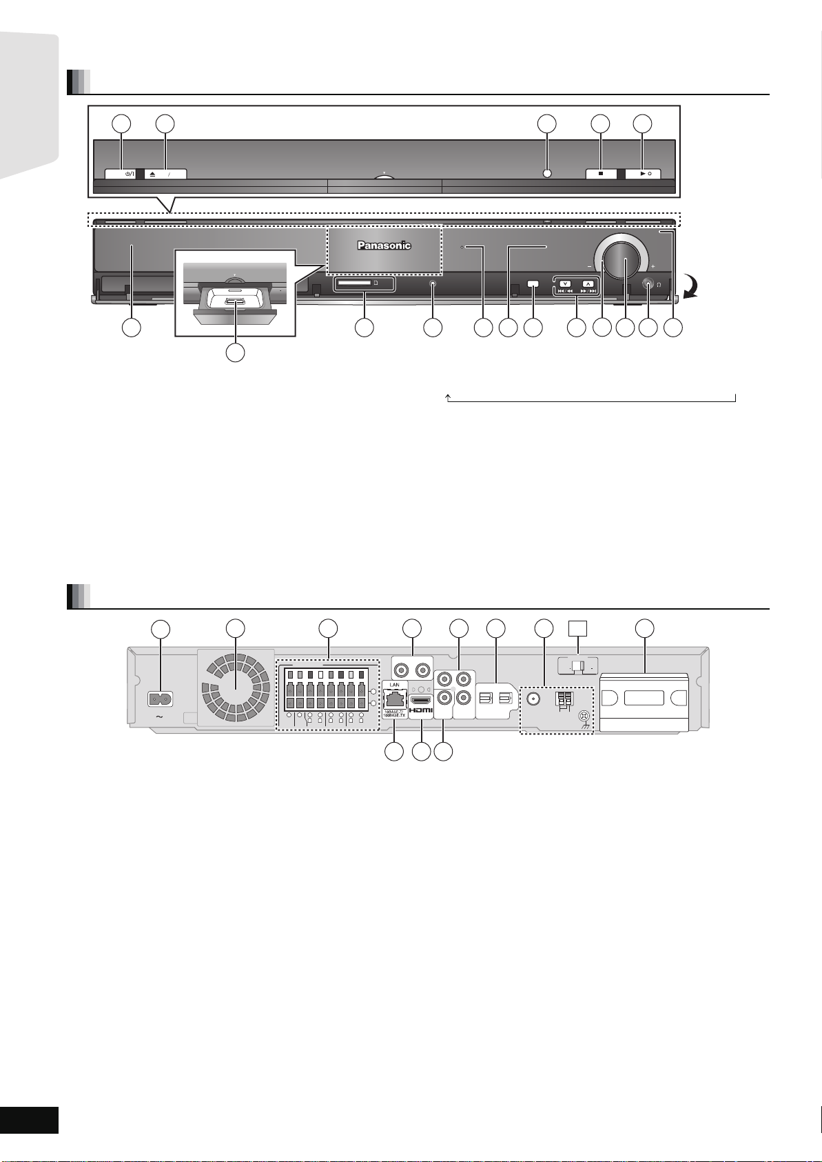
Front panel
1
POWER
2
OPEN CLOSE
Dock for iPod
7
1 Standby/on switch (POWER Í/I) (> 19)
Press to switch the unit from on to standby mode or vice versa. In
standby mode, the unit is still consuming a small amount of power.
2 Open or close the disc tray ( > 19)
3 [BT300] \BT303\ [BT200] : SMART SETUP button (> 15)
[BT203] : EASY SETUP button (> 15)
4 Stop (> 19)
5 Start play (> 19)
6 Disc tray (> 19)
7 Connect iPod (> 30)
8 SD card slot (> 19)
9 [BT300] \BT303\ [BT200] :
Connect Auto speaker setup microphone (> 15)
: The indicator lights when there is surro und sound effect. (> 18)
; Display
Dock for iPod
SURROUND OUTPUT
SD CARD
SETUP MIC
8 96 10 1311
< Select the source
BD/DVD ) SD )IPOD ) FM )AM )AUX )D-IN 1 )D-IN 2
“SD” on the unit’s display is not displayed when the SD card is not in
the SD card slot.
= Skip or slow-sear ch play (> 20) / Select the radio stations (> 26)
> Volume indicator
≥It is possible to set the indicator to turn on/off. (> 38, FL Display)
? Adjust the volume of the main unit (> 19)
≥When pulled hard, the volume knob may come off.
To prevent children from swallowing the volume knob, do not pull
off the volume knob.
onne ct he adp ho ne s (not inclu d ed ) (> 19)
@ C
A Remote control signal sensor
3 4 5
SMART SETUP
TUNE
SELECTOR
12
14
15
VOLUME
Pull open
1716
Rear panel terminals
1 AC IN
2 Cooling fan
3 SPEAKERS terminal (> 9)
4 AUX(TV) terminal (> 10, 11)
5 COMPONENT VIDEO OUT terminal (> 11)
6 OPTICAL DIGITAL IN terminals
T terminal (> 14)
[For[units[with[PX[printed[on[the[packaging[
* The terminal is not polarized.
This terminal can also be used for equipment other than the TV.
Terminal 1(TV) is designated for connection with the TV (> 10, 11)
Terminal 2(STB) can be used with equipment other than the STB
(> 12)
7 Radio antenna terminals (> 13)
8 Digital transmitter dock (> 45)
9 LAN port (> 14)
: HDMI AV OUT terminal (> 11)
; VIDEO OUT terminal (> 10)
[For[units[with[PX[printed[on[the[packaging[
qR AC Voltage selector (> 14)
RQT9508
6
Page 7
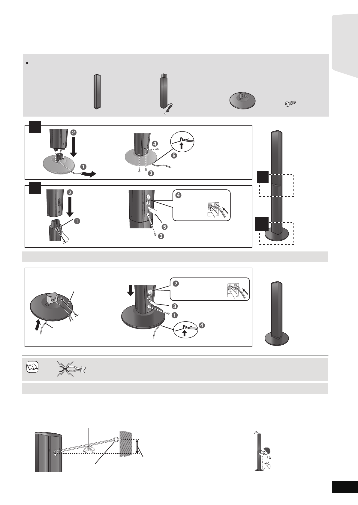
Assembling the speakers
2 Front speakers 2 Stands
(with cables)
2 Bases 8 Screws
Make sure you have all the indicated components before starting assembly, setup, and connection.
Keep the screws out of reach of children to prevent swallowing.
1
2
2
1
1
Slide into the groove.
Press into the groove.
Tighten securely.
Tighten securely.
Position the cable
between the ridges.
Leave about 120 mm (4
23
/32)
Insert the wire fully.
: White
: Blue
Push!
Slide into
the groove.
Press into the groove.
Tighten securely.
Insert the wire fully.
: White
: Blue
Push!
Leave about 120 mm (4
23
/32)
You can remove and use the cable
from the stand. To reattach the
cable, refer to page 46.
Thread the speaker cable
through the base.
Attach the speaker.
NOTE
DO
NOT
Getting started
[BT300] \BT303\ : Front spea k ers
Preparation
≥To prevent damage or scratches, lay down a soft cloth and perform
assembly on it.
≥For assembly, use a Phillips-head screwdriver (not included).
≥For optional wall mount, refer to page 46.
Speaker assembly option
Do
≥Be careful no t to cross (short-circuit) or rever s e the polarity of the speak er wires as doing so m ay damage the
speakers.
Not
Preventing the front speakers from falling
≥You will need to obtai n the appropriat e screw eyes to match t he walls o r pillars to which they are going to be fa stened.
≥Consult a qualified housing contractor concerning the appropriate procedure when attaching to a concrete wall or a surface that may not have
strong enough support. Improper attachment may result in damage to the wall or speakers.
e.g.
String (not included)
Thread from the wall to the speaker and tie tightly.
Screw eye
Rear of the speaker
(not included)
Wall
Approx.
150 mm
(5
29
/32)
Caution
≥Do not stand on the base. Be cautious when children are near.
e.g.
RQT9508
7
Page 8
Getting Started
NOTE
NOTE
DO
NOT
DO
Getting started
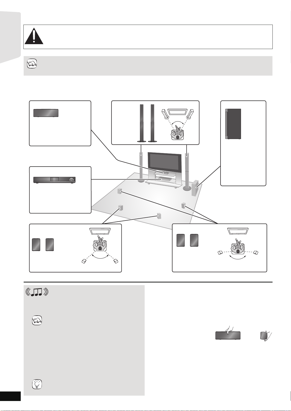
Positioning
Caution
≥The main unit and supplied speakers are to be used only as indicated in this setup. Failure to do so may lead to damage
to the amplifier and/or the speakers, and may result in the risk of fire. Consult a qualified service person if damage has
occurred or if you experience a sudden change in performance.
≥Do not attempt to attach these speakers to walls using methods other than those described in this manual.
How you set up your speakers can affect the bass and the sound field.
≥Place speakers on fl at secure bases.
≥Placing speakers t oo close to floors, walls, and corners can resu lt in excessive bass. Cover walls and windows with thic k curtains.
≥For optional wall mount, refer to page 46.
Keep your speakers at least 10 mm (
Setup example
Place the front, center, surround and surround back speakers at approximately the same distance from the seating position. Using “SMART
SETUP” (> 15) is a convenient way to get the ideal surround sound from your speakers when you are unable to place them. The angles in the
diagram are approximate.
Center speaker
Put on a rack or shelf. Vibration
caused by the speaker can
disrupt the picture if it is placed
directly on the TV.
Main unit
13
/32q) away from the system for proper ventilation.
Front
speakers
e.g., [BT300]
[BT303]
45º to 60º
Subwoofer
Place to the right or
left of the TV, on the
floor or a sturdy shelf
so that it will not
cause vibration.
Leave about 30 cm
13
(11
/16) from the TV.
RQT9508
8
To allow for proper ventilation
and to maintain good airflow
around the main unit, position
it with at least 5 cm (2) of
space on all sides.
Surround back
speakers*
Position the speakers as
illustrated and place them
about 1 m (3 ft) higher
than ear level.
* It is recommended to pl ace all the surround and surround back speakers at appro x imately the same h eight.
Connection with a wireless system
Optional Panasonic wireless accessory
SH-FX70
It is als o possible to connect the Surround and
Surround back speakers with 2 sets of the optional
Panasonic wireless system SH-FX70. (> 45)
≥Use only supplied speaker s
Using other spea k ers can dam age the unit , an d
sound quality will be negatively affected.
≥You can damage your speakers and shorten their
useful life if you play sound at high levels over
extend ed periods.
≥Reduce the volume in the following cases to avoid
damage:
–When playing distorted sound.
–When the spe akers are reverberating due to a
record player, noise from FM broadcasts, or
continuous signals from an oscillator, test disc, or
electro ni c ins t ru m en t .
–When adjusting the sound quality.
–When turning the unit on or off.
≥Positioning speakers in front
It is possible to locate all the speakers in front of the
TIPS
listening position. However the optimal surround
sound effect may not be ob tainable.
60º to 90º
If irregular color ing occurs on your TV
The center speaker is designed to be used close to a TV, but the
picture may be affected with some TVs and setup combinations.
If this occurs, turn the TV off for about 30 minutes.
The demagnetizing function of the TV should correct the problem. If it
persists, move the speakers further away from the TV.
Caution
Do not touch the front netted area of the speakers. Hold by the sides.
e.g., Center speaker
Surround speakers*
Position the speakers
as illustrated and
place them about
1 m (3 ft) higher than
ear level.
160º to 170º
Page 9
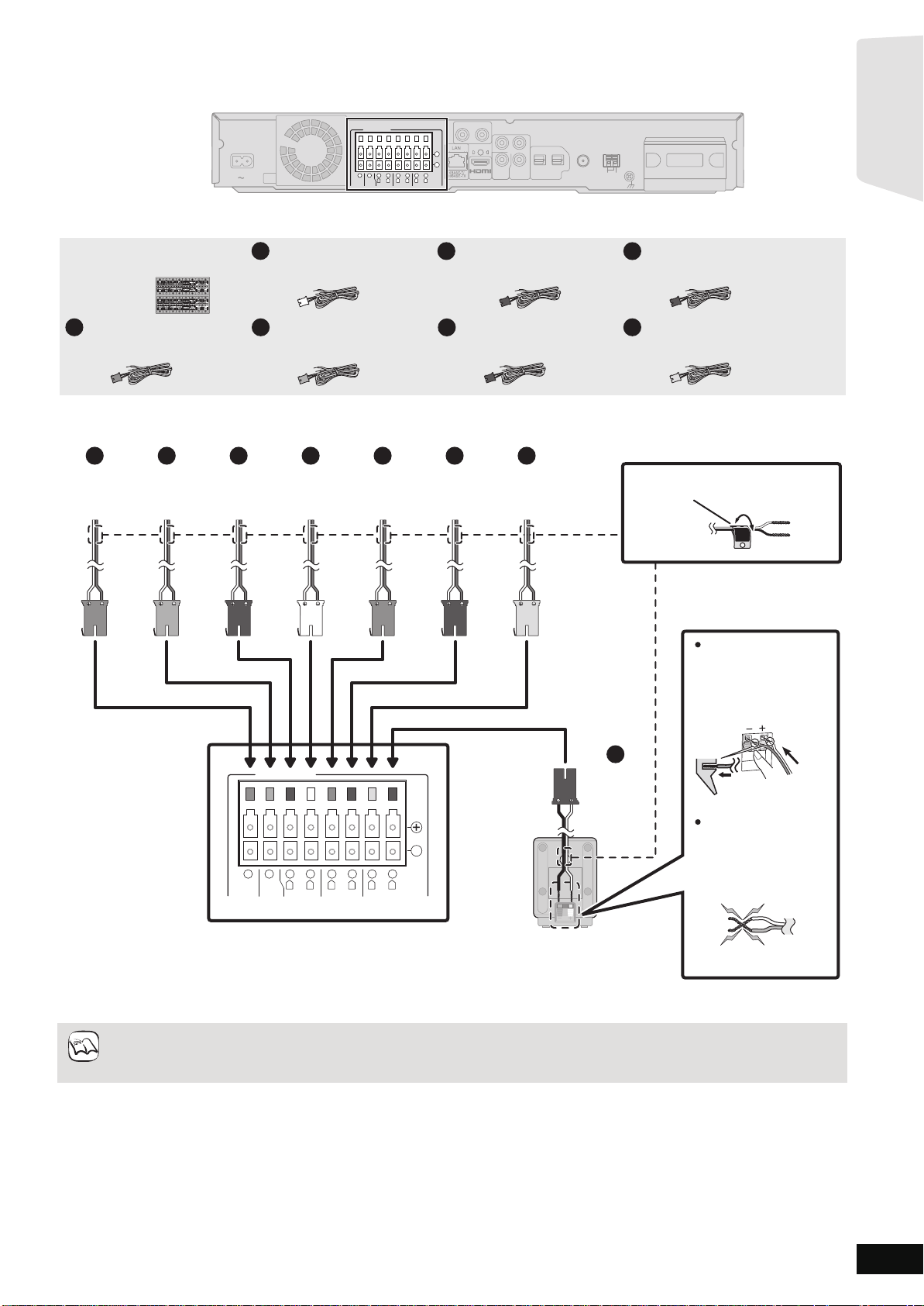
Spea ker connec tions
OPTICAL
2(STB) 1(TV)
L
R
DIGITAL IN
COMPONENT
VIDEO OUT
VIDEO
OUT
Y
AUX(TV)
P
R
PB
SPEAKERS
AV OUT
)
(
CENTER
3
Ω
3Ω3
Ω
WOOFERWOOFER
SUB-
FRONT
3
Ω
SURROUND
3
Ω
SURROUND BACK
AC IN
R
L
6
5
2
1
R
L
4
3
R
L
8
7
-
TRANSMITTER
DIGITAL
Main unit
+
ANT
EXT
LOOP
AM
GNDANTLOOP
FM ANT
75Ω
TRANSMITTER
DIGITAL
PUSH PUSH
Main unit
Surround back speaker (L)
1
FRONT
Lch
Push!
e.g., Front speaker (L)
Speaker cable sticker (included)
: White
: Blue
6
GRAY
SURROUND
TAN
SURROUND
BACK (Rch)(R
ch)
BLUE
SURROUND
(L
ch)
RED
FRONT
(R
ch)
WHITE
FRONT
(L
ch)
PURPLE
SUBWOOFER
GREEN
CENTER
1
2
3
4
5
8
7
BROWN
SURROUND
BACK (Lch)
Insert the wire fully,
taking care not to insert
beyond the wire
insulation.
Be careful not to cross
(short-circuit) or reverse
the polarity of the
speaker wires as doing
so may damage the
speakers.
Do not
NOTE
Getting started
Turn off al l equipment befor e connec tion and read the appropr iate operating instructions.
Do not connect the AC power supply cord until all other connec tions are complete.
Setup example
Sheet of speaker cable
stickers
Speaker cable for front
1
speaker (L) (White)*
Speaker cable for front
2
speaker (R) (Red)*
Speaker cable for surround
3
speaker (L) (Blue)
Speaker cable for surround
4
speaker (R) (Gray)
Speaker cable for center
5
speaker (Green)
Speaker cable for surround
7
back speaker (L) (Brown)
* [BT300] \BT303\ : The speaker cables are attached to the speaker stan ds.
≥Refer to the rear label of the speaker before connecting the appropriate cable.
≥Pa y at t en t io n to th e typ e of sp ea ke r and th e co nn ec tor color w he n yo u place the spe ak ers.
SPEAKERS
+
-
4
6
3
Ω
SUB-
WOOFER
5
3Ω3
CENTER
2
Ω
R
FRONT
1
L
3
3
Ω
R
L
SURROUND
8
7
3
Ω
R
L
SURROUND BACK
Speaker cable for surround
8
back speaker (R) (Tan)
Connect to the main unit’s terminals of the same color when you m ake the speaker connection.
Use of the speaker-cable stickers is convenient when maki ng cable connections.
≥Do not use a f ront speaker as a surrou nd, surround back speaker or vic e versa. Verify the type of speaker with the label on
the rea r of the speaker.
≥Match the connector co lor and th e type of speaker as shown above.
RQT9508
9
Page 10
TV connections
1
Video cable
COMPONENT
VIDEO OUT
PR
PB
ANT
EXT
LOOP
AM
GNDANTLOOP
VIDEO
OUT
OPTICAL
2(STB) 1(TV)
DIGITAL IN
OPTICAL
2(STB) 1(T
L
R
DIGITAL IN
COMPONENT
VIDEO OUT
Y
AUX(TV)
P
R
PB
SPEAKERS
-
AV OUT
R
L
CENTER
3Ω3
Ω
WOOFER
FRONT
6
5
2
1
R
L
3
Ω
SURROUND
4
3
R
L
3
Ω
SURROUND BACK
8
7
AC IN
VIDEO
OUT
TIPS
Getting started
AUX(TV)
AUX(TV)
R
R
L
SPEAKERS
+
AC IN
3
Ω
SUB-
WOOFER
2
1
6
5
3Ω3
Ω
R
L
CENTER
FRONT
4
3
Ω
R
SURROUND
8
3
3
Ω
R
L
SURROUND BACK
-
7
L
Main unit
My TV has COMPONENT VIDEO IN terminals and HDMI IN terminal. Which should I connect with?
≥The different levels of picture quality input are listed below in order from highest to lowest.
HDMI IN )COMPONENT VIDEO IN )VIDEO IN.
However, it will take longer for the picture output to start up when this unit is connected with the HDMI IN terminal.
–To enjoy all features of this unit, connect the video cable, even if the component video cable or the HDMI cable is used.
For connections with a video cable (> below)
For connections with a component video cable (> 11)
For connections with an HDMI cable (> 11)
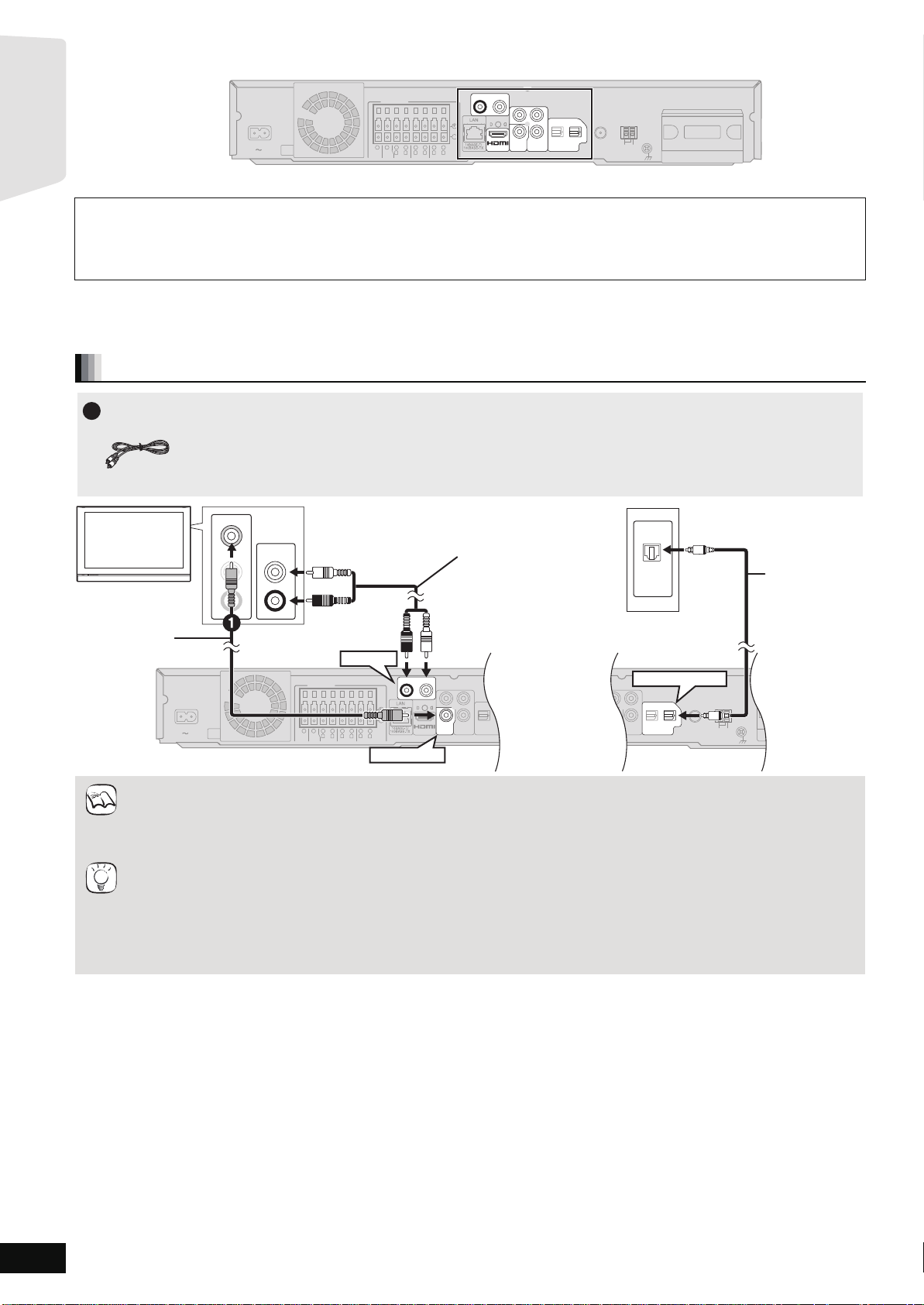
Connections with a video cable
L
Y
PB
Y
PB
Y
PB
OPTICAL
OPTICAL
P
P
P
R
R
R
2(STB) 1(TV)
2(STB) 1(TV)
COMPONENT
COMPONENT
COMPONENT
VIDEO
VIDEO
(
VIDEO
OUT
OUT
OUT
)
VIDEO OUT
VIDEO OUT
VIDEO OUT
DIGITAL IN
AV OUT
AV OUT
DIGITAL IN
FM ANT
DIGITAL
DIGITAL
TRANSMITTER
PUSH PUSH
LOOP
75Ω
EXT
ANT
AM
GNDANTLOOP
TRANSMITTER
TV
VIDEO IN
AUDIO IN
Audio cable*
AUDIO OUT
L
L
R
R
(not included)
The optical digital audio
cable can be used when
connecting to televisions
with optical out terminals
( right).
1
OPTICAL
OUT
Video cable
(included)
AUX(TV)
OPTICAL 1(TV)
+
Main unit
(
3
Ω
SUB-
)
VIDEO OUT
75Ω
FM ANT
≥Set “High Clarity Sound” in the on-screen menu to “Off” (> 36). (Otherwise, the video will not be output.)
Optional connections
≥For those w ho want to enjoy higher picture quality and have a TV equipped with an HDMI IN terminal (> 11)
NOTE
≥For those who want to enjoy higher picture quality and have a TV equipped with a COMPONENT VIDEO IN terminal (> 11)
≥For those who have a Set Top Box (Satellite receiver, Cable box, etc.) or video cassette recorder (> 12)
T o enjoy TV audio f rom this ho me theater system’s speakers
*1 You can enjoy the audio from your TV through this home theater system’s speakers by connecting to the “AUX(TV)” terminal or
“OPTICAL 1(TV)” terminal. (> 27)
*2 This is the preferred connection for best sound and true surround sound.
This unit can decode the surround signals received from your TV. Refer to the operating instructions for the TV for the settings
necessary to output its audio from the digital audio output to your home theater system. Only Dolby Digital and PCM can be played
with this connection.
–After making this connection, make settings to suit the type of audio from your digital equipment (> 27).
Optical digital
audio cable*
(not included)
1,2
RQT9508
10
Page 11
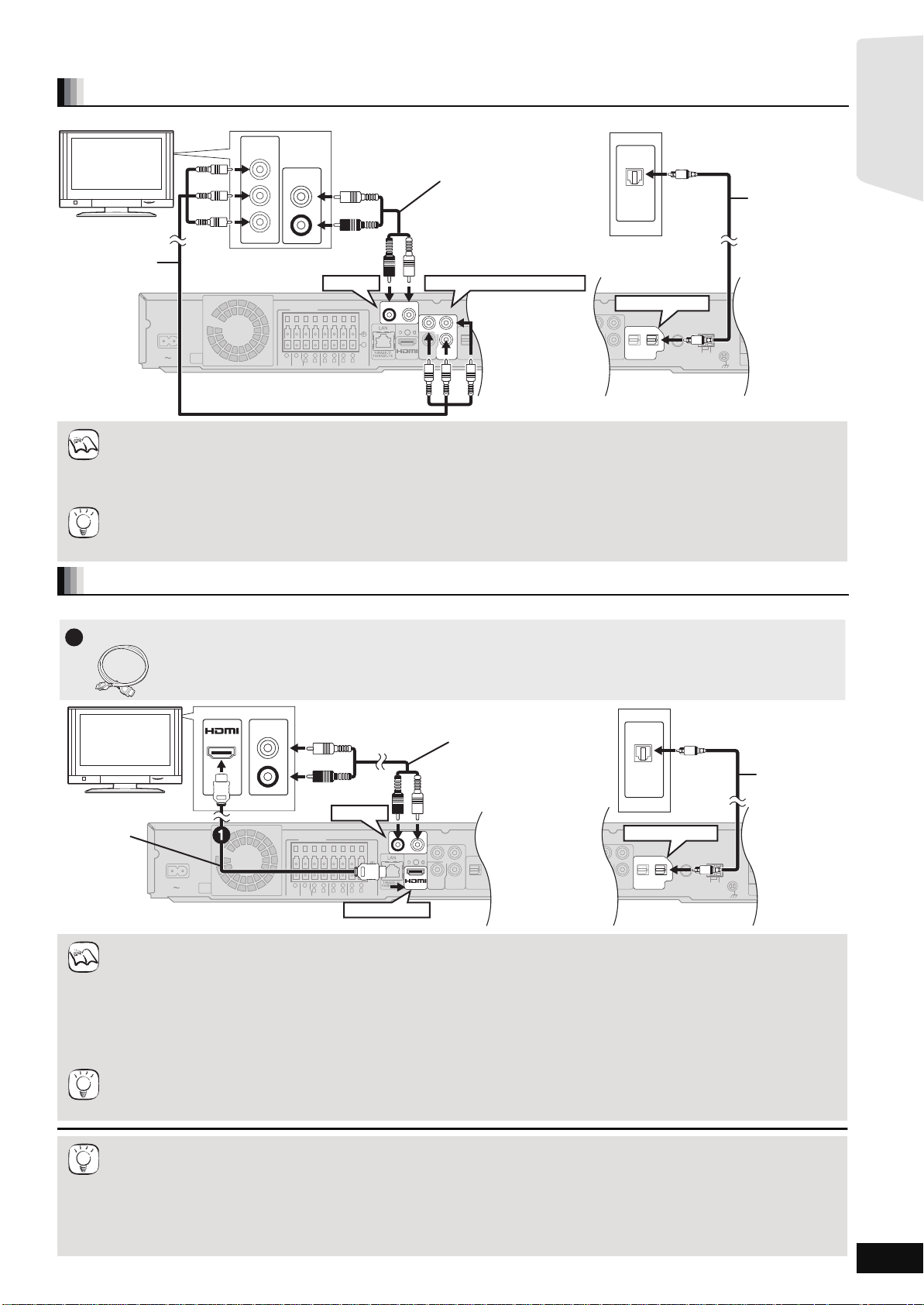
Connections with a component video cable
COMPONENT
VIDEO OUT
P
R
P
B
ANT
EXT
LOOP
AM
GNDANTLOOP
VIDEO
OUT
OPTICAL
2(STB) 1(TV)
DIGITAL IN
FM ANT
75Ω
OPTICAL
2(STB) 1(T
L
R
DIGITAL IN
COMPONENT
VIDEO OUT
Y
AUX(TV)
P
R
P
B
SPEAKERS
+
-
AV OUT
R
L
CENTER
3Ω3
Ω
WOOFER
FRONT
6
5
2
1
R
L
3
Ω
SURROUND
4
3
R
L
3
Ω
SURROUND BACK
8
7
AC IN
VIDEO
OUT
COMPONENT
VIDEO OUT
Y
P
R
P
B
VIDEO
OUT
)
(
3
Ω
SUB-
L
R
AUDIO OUT
OPTICAL
OUT
COMPONENT
VIDEO IN
Y
P
R
PB
AUX(TV)
OPTICAL 1(TV)
COMPONENT VIDEO OUT
Optical digital
audio cable*
1,2
(not included)
TV
Audio cable*
1
(not included)
The optical digital audio
cable can be used when
connecting to televisions
with optical out terminals
( right).
Main unit
Component
Video cable
(not included)
NOTE
TIPS
1
[BT303] HDMI cable
COMPONENT
VIDEO OUT
PR
PB
ANT
EXT
LOOP
AM
GNDANTLOOP
VIDEO
OUT
OPTICAL
2(STB) 1(TV)
DIGITAL IN
OPTICAL
2(STB) 1(T
L
R
DIGITAL IN
COMPONENT
VIDEO OUT
Y
AUX(TV)
P
R
PB
SPEAKERS
-
AV OUT
R
L
CENTER
3Ω3
Ω
WOOFER
FRONT
6
5
2
1
R
L
3
Ω
SURROUND
4
3
R
L
3
Ω
SURROUND BACK
8
7
AC IN
VIDEO
OUT
VIDEO
OUT
AV OUT
+
FM ANT
75Ω
3
Ω
)
(
WOOFER
SUB-
OPTICAL
OUT
AV IN
L
R
AUDIO OUT
OPTICAL 1(TV)
AUX(TV)
HDMI AV OUT
Optical digital
audio cable*
1,2
(not included)
Audio cable*
1
(not included)
The optical digital audio
cable can be used when
connecting to televisions
with optical out terminals
( right).
Main unit
HDMI cable
(only included
with SC-BT303)
HDMI
compatible
TV
NOTE
TIPS
Getting started
Do not disconnect the video cable even if the below is connected. Some features may not be displayed.
≥Connect to terminals of the same color.
≥Set “Black Level Control” to “Darker”. (> 37)
≥Using the COMPONENT VIDEO OUT terminal, while playing DVD-Video, the video output resolution is limited to “480p”.
≥Be sure your TV supports at least 480p. Set “Component Video Resolution” to “480p”, “720p” or “1080i”. (> 39)
≥Set “High Clarity Sound” in the on-screen menu to “Off” (> 36). (Otherwise, the video will not be output .)
To enjoy high definition/progressive video
≥Connect to a TV that supports 480p or higher.
≥Set “Component Video Resolution” to “480p”, “720p” or “1080i”. (> 39)
≥Set “HDMI Video Mode” to “Off”. (> 39) Otherwise, the video is output as 480i.
Do not disconnect the video cable even if the below is connected. Some features may not be displayed.
TIPS
Connections with an HDMI cable
≥\BT303\ : Do not use any other HDMI cables except the supplied one.
≥Non -H DM I-c om plia nt ca ble s ca nno t be utili ze d.
≥[BT300] [BT200] \BT203\ : Please use High Speed HDMI Cables that have the HDMI logo (as shown on the cover). It is
recommended that you use Panasonic’s HDMI cable.
Recommended par t number:
RP-CDHG10 (1.0 m/3.3 ft), RP-CDHG15 (1.5 m/4.9 ft), RP-CDHG20 (2.0 m/6.6 ft), RP-CDHG30 (3.0 m/9.8 ft),
RP-CDHG50 (5.0 m/16.4 ft), etc.
≥This unit incorporates HDMI (Deep Color, x.v.Color
≥When outputting 1080p signal (> 39, “HDMI Resolution”), please use HDMI cables 5.0 m (16.4 ft) or less.
NECESSARY SETTINGS
“HDMI Video Mode” : “On”/“HDMI Audio Output” : “Off” (> 39)
With this connection, you can use VIERA Link “HDAVI Control” (> 28).
T o enjoy TV audio from this home theate r system’s speakers
*1 You can enjoy the audi o from your TV through this home theater system’s speaker s by connecting to the “AUX(TV)” terminal or
“OPTICAL 1(TV)” terminal. (> 27)
*2 This is the preferred connection for best sound and true surround sound.
This unit can decode the surround signals received from your TV. Refer to the operating instructions for the TV for the settings
necessary to output its audio from the digital audio output to your home theater system. Only Dolby Digital and PCM can be played
with this connection.
–After making this connection, make settings to suit the type of audio from your digital equipment (> 27).
TM
, High Bit rate Audio) technology. (> 54, 55)
RQT9508
11
Page 12
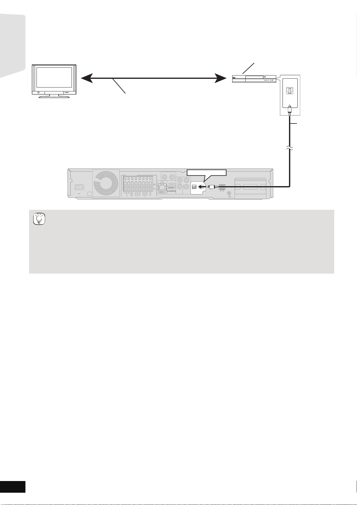
Connections to a Set Top Box, etc.
L
R
COMPONENT
VIDEO OUT
Y
AUX(TV)
P
R
PB
SPEAKERS
+
-
ANT
EXT
LOOP
AM
AV OUT
R
L
CENTER
3Ω3
Ω
WOOFER
FRONT
6
5
2
1
GNDANTLOOP
R
L
3
Ω
SURROUND
4
3
R
L
3
Ω
SURROUND BACK
8
7
AC IN
TRANSMITTER
DIGITAL
VIDEO
OUT
OPTICAL
2(STB) 1(TV)
DIGITAL IN
FM ANT
75Ω
)
(
3
Ω
SUB-
TRANSMITTER
DIGITAL
PUSH PUSH
OPTICAL
OUT
OPTICAL 2(STB)
TV
Optical digital
audio cable
(not included)
STB, VCR, DVD recorder, etc.
Refer to the operating instructions of the respective devices
for the optimal connections.
Main unit
TIPS
Getting started
Use the following connections when you want to output the original surround audio from your Set Top Box, cable TV, VCR, DVD recorder, etc.
through this unit’s speakers.
≥Do not connect through the video cassette recorder.
Due to copy guard protection, the picture may not be displayed properly.
≥Turn off all equipment before connection.
≥This unit can decode the surround sign al from the Set Top Box (Satellite receiver, Cable box, etc.).
“
Press [EXT-IN] several times to select
D-IN 2” (DIGITAL IN 2*).
* “(CABLE/SAT)” is displayed next to DIGITAL IN 2 when set for CABLE/SA T A UDIO inpu t. ( > 28, Set ti ng th e TV au di o f or VI ER A Lin k
“HDAVI Control”)
≥For connections between this unit and the TV, refer to “TV connections”. (> 10, 11)
≥If you have various sound sources and this unit’s terminals are not sufficient, connect them to the available inputs on the TV and the
TV output should then be connected to the “AUX(TV)” or “OPTICAL 1(TV)” terminal of the main unit.
Refer to the operating instructions of the TV, video cassette recorder, DVD recorder or Set Top Box for settings to output its audio via
AUDIO OUT or OPTICAL OUT terminal of the TV.
–In some cases t he audio signal will only be output as 2ch audio from the TV. In this case, connect the Set Top Box (Satellite
receiver, Cable box, etc.) that will be used most commonly w ith multi-channel audio to this unit’s “OPTICAL IN 2(STB)” terminal.
RQT9508
12
Page 13
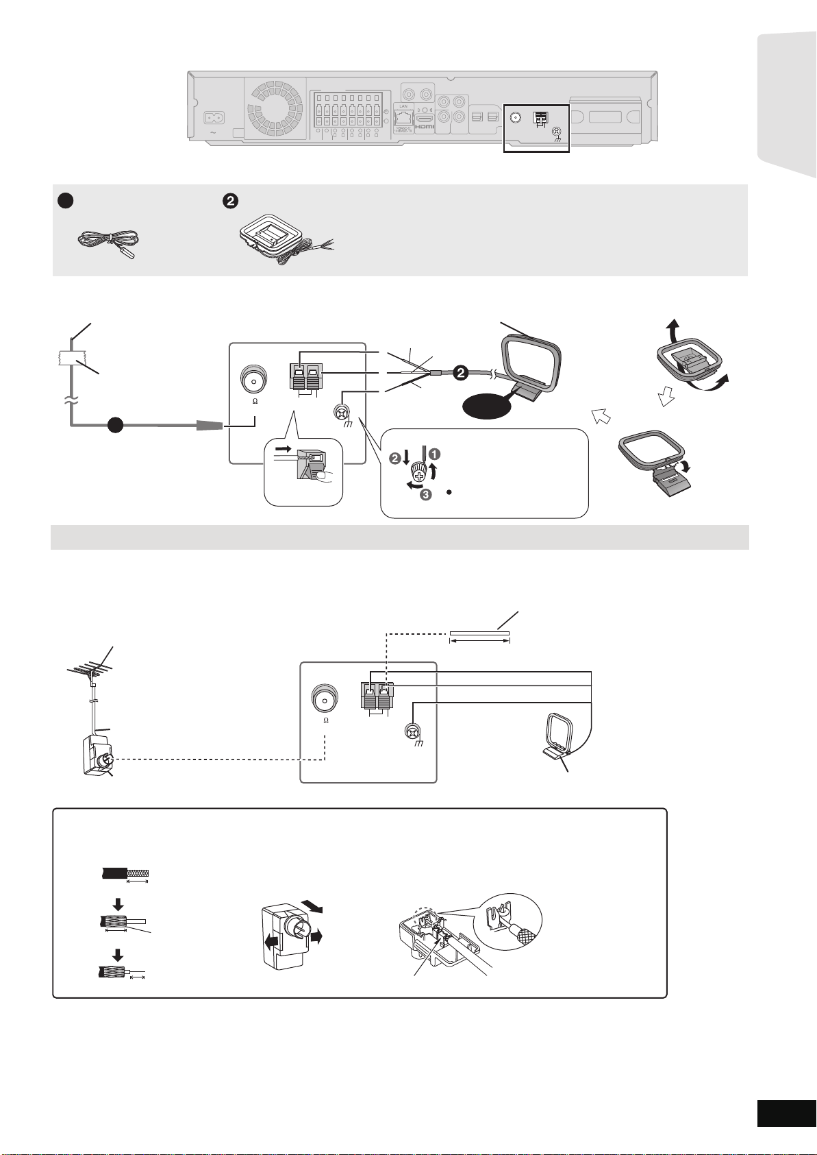
Radio antenna connections
AM ANTFM ANT
EXTLOOP
75
LOOP ANT GND
Red
White
Black
Main unit
Push!
Adhesive
tape
FM indoor antenna (included)
Affix this end of the antenna
where reception is best.
AM loop antenna (included)
Stand the antenna up on its base.
Place the antenna where reception is best.
Click!
1
Use a Phillips-head
screwdriver, etc.
(not included)
Do not screw too tightly.
AM ANTFM ANT
EXTLOOP
75
LOOP ANT GND
e.g.
Antenna plug (not included)
*
Rework your outdoor antenna's 75 coaxial cable as follows.
Peel back
7 mm (
9
/32)
10 mm (
13
/32)
10 mm (
13
/32)
Remove a piece of the
outer vinyl insulator.
Carefully pull the tabs
apart to remove the cover.
Install the coaxial cable.
Clamp the cable conductor,
and wind it on so that it does
not contact anything else.
Attach the cover.
Clamp with pliers
75 coaxial cable*
(not included)
FM outdoor antenna
[Using a TV antenna (not included)]
The antenna should be installed by a
competent technician.
AM outdoor antenna
[Using a vinyl wire (not included)]
Run a piece of vinyl wire horizontally
across a window or other convenient
location.
Leave the AM loop
antenna connected.
Main unit
5 m to 12 m
(16 ft to 39 ft)
Getting started
AUX(TV)
R
SPEAKERS
AC IN
3
Ω
WOOFER
2
1
6
5
3Ω3
Ω
R
L
SUB-
CENTER
FRONT
SURROUND
Main unit
≥Keep loose antenna cables away from other wires and cables.
4
3
Ω
R
8
3
3
Ω
R
L
SURROUND BACK
+
-
7
L
L
Y
PB
P
R
COMPONENT
(
VIDEO
OUT
)
AV OUT
VIDEO OUT
OPTICAL
2(STB) 1(TV)
DIGITAL IN
FM ANT
DIGITAL
DIGITAL
TRANSMITTER
PUSH PUSH
75Ω
LOOP
EXT
AM
ANT
GNDANTLOOP
TRANSMITTER
FM Indoor antenna
1
AM loop antenna
Using an FM/AM outdoor antenna (optional)
Use outdoor antenna if FM/AM radio recep tion is poor.
≥Dis c on nect the ant en na wh en the un it is not in us e.
≥Do not use the outdoor antenna during an electrical stor m.
RQT9508
13
Page 14
Broadband Network Connections
Main unit
+
OPTICAL
2(STB) 1(TV)
L
R
DIGITAL IN
COMPONENT
VIDEO OUT
Y
AUX(TV)
P
R
PB
SPEAKERS
-
ANT
EXT
LOOP
AM
AV OUT
R
L
CENTER
3Ω3
Ω
WOOFER
FRONT
6
5
2
1
GNDANTLOOP
R
L
3
Ω
SURROUND
4
3
R
L
3
Ω
SURROUND BACK
8
7
AC IN
TRANSMITTER
DIGITAL
VIDEO
OUT
VIDEO
OUT
AV OUT
FM ANT
75Ω
3
Ω
SUB-
)
(
TRANSMITTER
DIGITAL
PUSH PUSH
LAN
Straight LAN cable (not included)
Internet
Broadband router, etc.
Telecommunications equipment
(modem, etc.)
NOTE
1
AC power supply cord
[For[the[U.S.A.[and[Canada[
Power plug adaptor
[For[units[with[PX[printed[on[the[packaging[
If the power plug does not fit your AC outlet,
use the power plug adaptor (included).
If it still doesn't fit, contact an electrical parts
distributor for assistance.
Main unit
OPTICAL
2(STB) 1(TV)
L
R
DIGITAL IN
COMPONENT
VIDEO OUT
Y
AUX(TV)
P
R
PB
SPEAKERS
+
-
FM ANT ANT
EXT
LOOP
AM
75Ω
AV OUT
)
(
R
L
CENTER
3
Ω
3Ω3
Ω
WOOFER
SUB-
FRONT
6
5
2
1
GNDANTLOOP
R
L
3
Ω
SURROUND
4
3
R
L
3
Ω
SURROUND BACK
8
7
AC IN
TRANSMITTER
DIGITAL
VIDEO
OUT
COMPONENT
VIDEO OUT
Y
P
R
PB
VIDEO
OUT
1
AC power supply cord (included)
To a household AC outlet
110
127V
220
240V
VOLT ADJ
[For[units[with[PX[printed[on[the[
[packaging[
Before connecting the AC power supply cord;
[For[units[with[PX[printed[on[the[
[packaging[
The AC IN terminal is
not polarized.
Set the voltage.
Use a flat-head screwdriver to
move the voltage selector to the appropriate
position for the area in which this system is
used.
110
127V
220
240V
VOLT ADJ
[For[the[U.S.A.[and[Canada[
(AC 120 V, 60 Hz)
[For[units[with[PX[printed[on[the[packaging[
(AC 110 V to 127V, 220 V to 240 V , 50 Hz/60 Hz)
NOTE
TIPS
Getting started
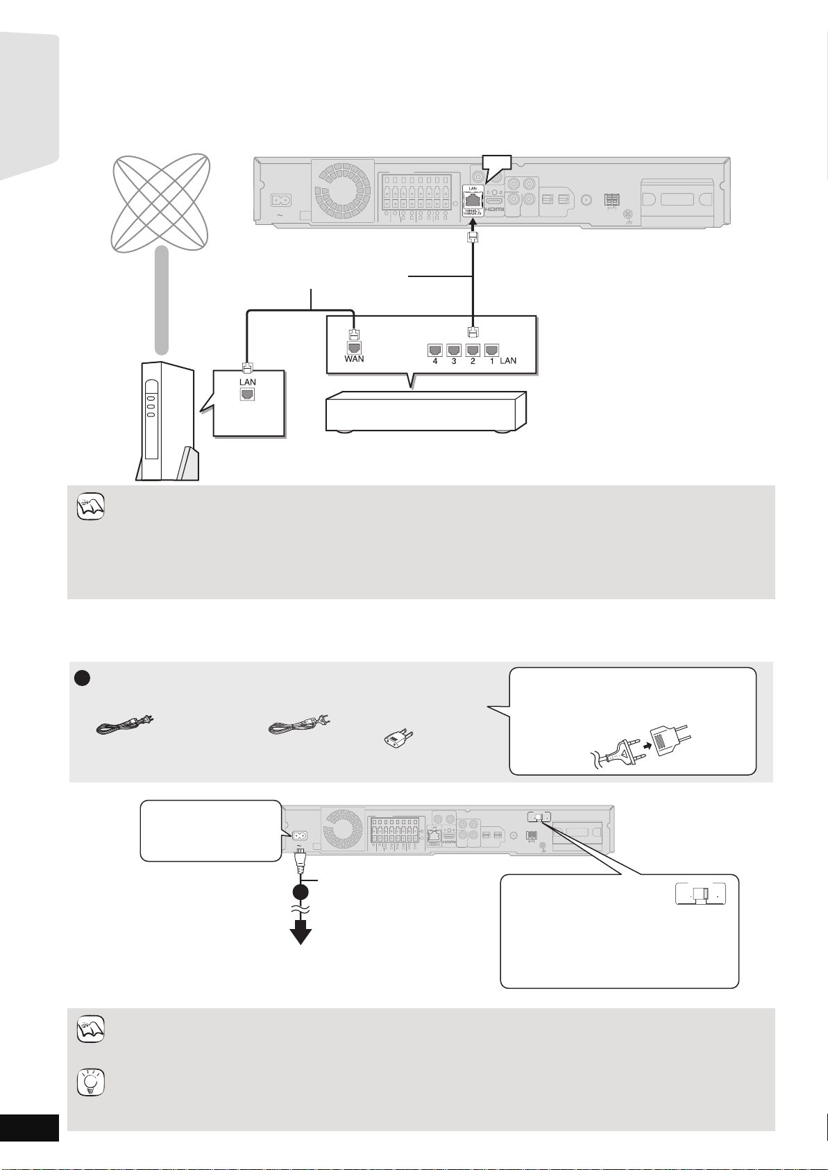
The following s ervices can be used w hen this unit is co nnected to the internet via a broadband conn ection.
≥Firmware ca n be update d (> 32)
≥You can enjoy the BD-Live (> 22)
≥You can enjoy the VIERA CAST (> 32)
≥Use shielded LAN cables when connecting to peripheral devices.
≥With installation where your broadband modem is connected di rectly to your PC, a router mus t be installed.
≥Use a router that supports 10BA SE-T /100B ASE-T X.
≥In case all available connection on your router is being used, a hub or switch can be installed to provide additional conn ections.
≥When opera ti ng the V IE RA C AS T, u se hi gh -spe ed in te rne t serv ic e no le ss th an 1. 5 M bp s f o r SD ( S tandard Defini ti on ) an d 6 Mbp s for
HD (High Definition) picture qual ity by your local broadband company.
–If using slow Internet connection, the video may not be displayed correctly.
≥After physically connecting this unit to your broadband connection, some configuration is required. (> 33)
≥Inserting any cabl e other than a LAN cable in the LAN terminal can damage the unit.
AC power supply cord connection
≥Before turning the power on for the first time, be sure to read the preparations for SMART SETUP / EASY SETUP. (> 15)
RQT9508
14
Conne ct only after all other connections are complete.
Cons erving power
The main unit consumes a small amount of AC power, even when it is turned off ([For[the[U.S.A.[and[Canada[ approx. 0.2W ,
[For[units[with[PX[printed[on[the[packaging[ approx. 0.3W). To save power when the unit is not to be used for a long time, unplug it from
the ho usehold AC outlet.
Y o u will need to reset some memory items after plugging in the main unit.
Page 15
SMART SETUP / EASY SETUP
1
Auto speaker setup microphone
1
RETURN
OK
BD/SD
RETURN
BD/SD
OK
TUNE
SELECTORSETUP MIC
SD CARD
[BT300] [BT303] [BT200]: SMART SETUP
[BT203]: EASY SETUP
Getting started
The SMART SETUP / EASY SETUP screen assists you to make the necessa ry settings.
When the system is switched on for the first time, the SMART SETUP / EASY SETUP screen for the basic settings is displayed automatically.
Follow the on-screen prompts to make basic settings for the system.
[BT300] \BT303\ [BT200]:
\BT203\: EASY SETUP
[BT300] \BT303\ [BT200]: Preparation
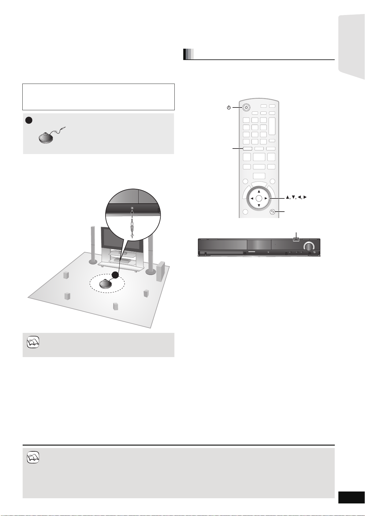
To optimize the surround sound experience we recommend that you
setup the speaker output level using the Auto speaker setup function.
Keep as quiet as possible during the Auto speaker setup. Loud
voices, air-co nditioning noi se, or exce ssive win d may lead to
incorrect settings. The speakers output loud test signals during
setup.
≥Place the Auto speaker setup mic rophone at the actual seat ing
position. (At ear level when seated.)
≥A test signal is output from each speaker during the SMART SETUP.
≥After the SMART SETUP is completed, unplug the Auto speaker
setup microphone and keep it for future use.
SMART SETUP
Basic settings for the system
Preparation
Turn on your TV and selec t the appropriat e video input mode (e.g.,
VIDEO 1, AV 1, HDMI, etc.) to suit the connections to this unit.
≥To change your TV’s video input mode, refer to its operating
instructions.
≥This remote control can perform some basic TV operations (> 5).
≥Auto speaker setup can be activated through SMART
SETUP only.
≥Audio settings will be restored to default if the Auto
NOTE
NOTE
speake r setup is canceled.
≥If this unit is connected to a “HDAVI Control 3 (or later)” compatible TV via HDMI cable, the menu language and TV aspect
inform at i on wil l be ret r ie ve d vi a V IER A Link.
≥If this unit is connected to a “HD AVI Control 2” compatibl e TV via HDMI cable, the menu la nguage information will be retrieved via
VIERA Link.
≥Even if this unit is connected to a “HDAVI Control 2 (or later)” compatible TV via HDMI cable, the menu screen language will not be
automatically retrieved if this unit does not support the language. In this case, set the language manually.
≥Settings in the SMART SETUP / EASY SETUP can also be changed in the player settings [e.g., language, TV aspect and speaker
level (> 37)].
≥Positioning examples for mounting all speakers in front. (> 8)
1 Press [Í].
≥When the SMART SETUP / EASY SETUP screen appears
automatically, skip step 2 and 3.
2 Press [BD/SD] to select “BD/DVD”.
3 Press [SMART SETUP] (or [EASY SETUP]) on
the main unit.
≥The SMART SETUP / EASY SETUP screen appears.
4 Follow the on-screen instructions and make the
settings with [3, 4, 2, 1] and [OK].
≥Language (> below)
Select the language used on menu screen.
≥TV Aspect (> below)
Select the aspect to suit you r TV and preference.
≥Speaker position
Specify the positioning of the surround and surround back
speakers.
≥[BT300] \BT303\ [BT200]: Auto Speaker Setup
Adjust t he speaker output level aut omatically
≥[BT203]: Speaker chec k
Check if the connection to each speaker is valid.
≥Speaker Output
Make surround sound setting for spe aker output.
≥TV Audio
Select the audio input connection from your TV.
For AUX connection (> 10): Select “AUX”.
For OPTICAL DIGITAL IN connection (> 10):
Select “DIGITAL IN 1”.
This will be the TV audio setting for VIERA Link “HDAVI
Control”. (> 28)
To return to the previous screen, press [RETURN].
5 Press [OK] to finish the SMART SETUP / EASY
SETUP.
RQT9508
15
Page 16
OK
S
T
A
R
T
OK
START
Menu
OK
RETURN
Other Functions
Playback DISC
Top Menu
Home theater START
BD-Video
Input Select
Sound(Equalizer)
Network
e.g., [BD-V]
e.g., [BD-V]
Getting started
RQT9508
16
Showing START menu
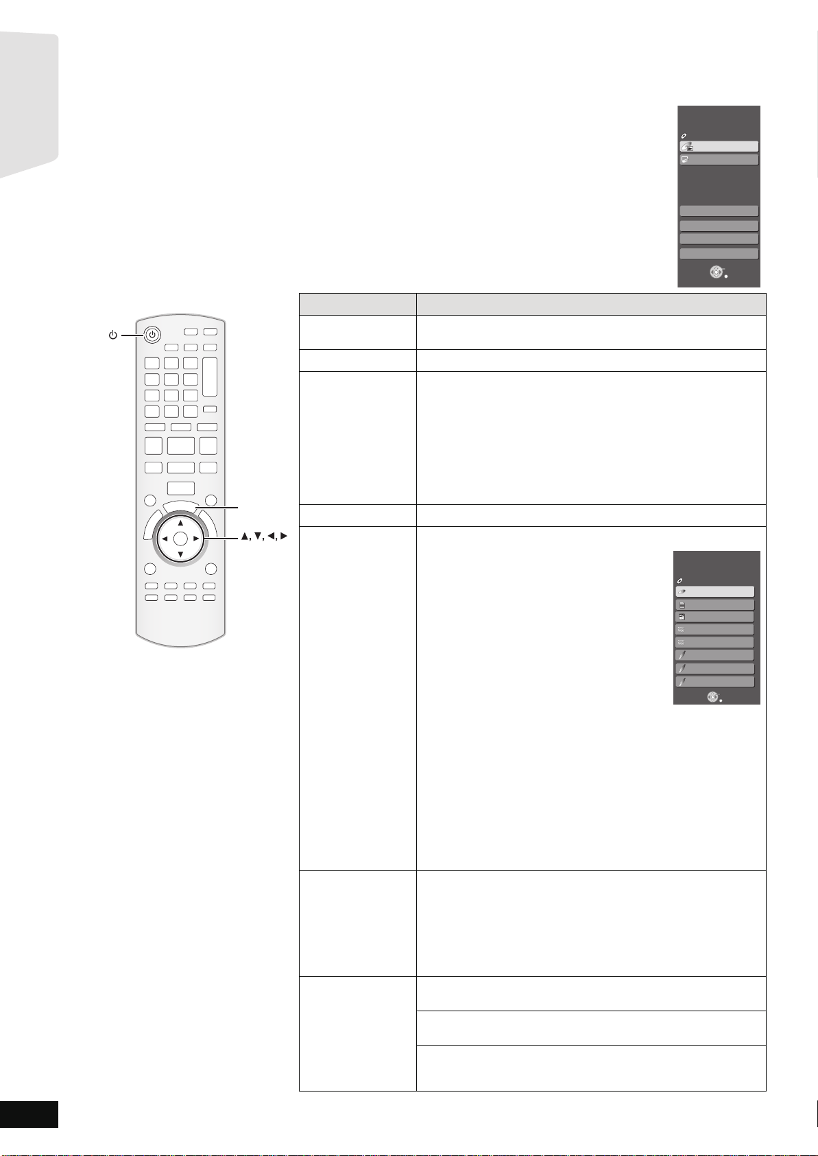
Some functions of this unit can be operated from the START menu.
1 Press [Í] to turn on the unit.
2 Press [START].
≥Items displayed vary according to the chosen selector and media.
3 Press [3, 4] to select
Items Functions
Playback DISC
Playback
Top Menu Shows the disc top menu.
Menu Shows the media menu.
Network Display Home screen of VIERA CAST (> 32)
Input Select
Sound(Equalizer) Flat:
Other Functions Setup:
the item and pr
ess [OK].
Starts playin g di sc /S D C ard.
To play AVCHD (> 21)
To play MPEG2 (> 21)
To play MP3, CD (> 25)
To play JPEG (> 23)
Shows the iPod menu.
T o play “Music” (> 31)
To play “Videos” (> 31)
To play “All (iPod display)” (> 31)
For “Playback Mode” (> 31)
Select the source.
BD/DVD/CD:
T o play BD-Video, DVD-Video, AVCHD
(> 19 to 22)
T o play JPEG (> 23)
T o play MP3, CD (> 25)
SD card:
T o play AVCHD (> 21)
T o play MPEG2 (> 21)
T o play JPEG (> 23)
iPod:
T o play iPod contents (> 31)
FM:
T o enjoy the FM radio (> 26)
AM:
T o enjoy the AM radio (> 26)
AUX (TV)*
DIGITAL IN 1 (TV)*
DIGITAL IN 2 (CABLE/SAT )*
1
:
To enjoy TV broadcasts with this unit’s speakers (> 27)
To enjoy TV broadcasts with this unit’s speakers (> 27)
1
:
2
:
Home theater START
Input Select
BD-Video
BD/DVD/CD
SD
SD card
iPod
FM
AM
AUX (TV)
DIGITAL IN 1
DIGITAL IN 2
OK
RETURN
T o enjoy audio from other devices with this unit’s speakers (> 27)
*1 “(TV)” is displayed next to items set for TV AUDIO input. (> 28,
Setting the TV audio for VIERA Link “HDAVI Control”)
*2 “(CABLE/SAT)” is displayed next to DIGITAL IN 2 when set for
CABLE/SAT AUDIO input. (> 28, Setting the TV audio for VIERA
Link “HDAVI Control”)
Cancel (no effect is added).
Heavy:
Adds punch to rock.
Clear:
Clarifies higher sounds.
Soft:
For background music.
You can change the unit’s settings using Setup menu (> 37).
Card M a nagement:
Formatting SD cards/Deleting data (> 22)
Playlists:
You can play playlists created on DVD-VR.
Press [3, 4, 2, 1] to select the playlist and press [OK].
Page 17
Selecting the playback source
BD/SD
iPod
NOTE
Getting started
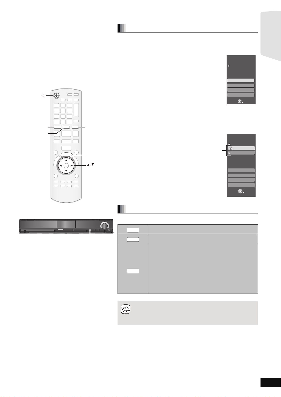
Selecting the source from the START menu
You can select sound modes, desi red source, or access playback/menus by using
the START menu.
1 Press [Í] to turn on the unit.
2 Press [START] to show the START menu.
3 Press [3, 4] to select the item and then
press [OK].
≥To exit press [START].
iPod
BD/SD
RADIO
iPod
EXT-IN
RADIO/EXT-INBD/SD
R
A
T
T
S
START
4 Press [3, 4] to make the setting.
When “Input Select” is selected
You can select a de sired sou rce from the menu.
≥BD/DVD/CD, SD card, iPod, FM, AM, AUX*
DIGITAL IN 2*
*1 “(TV)” is displayed next to items set for TV AUDIO input.
(> 28, Setting the TV audio for VIERA Link “HDAVI
Control”)
*2 “(CABLE/SAT)” is displayed next to DIGITAL IN 2 when set
for CABLE/SAT AUDIO input. (> 28, Setting the TV audio for VIERA Link
“HDAVI Control”)
When a disc is loaded or a SD card is inserted, you can also access playback or
menus from the START menu.
e.g., [BD-V]
2
(> 16)
1
, DIGI TAL IN 1*1,
Playback/menu access
Home theater START
No Disc
Network
Input Select
Sound(Equalizer)
Other Functions
OK
RETURN
Home theater START
BD-Video
Playback DISC
Top Menu
Menu
OK
SD CARD
SD CARD
OK
SELECTOR
SELECTOR
SELECTOR
Network
Input Select
Sound(Equalizer)
Other Functions
OK
RETURN
Selecting the source with the remote control
Press To select
TUNE
SELECTORSETUP MIC
TUNE
SELECTORSETUP MIC
TUNE
SELECTOR
SELECTOR
RADIO
EXT-IN
Press [SELECTOR] on the main unit to select source from the main unit.
≥Confirm the audio connection to the AUX or OPTICAL DIGITAL IN
≥Reduce the volume on the TV to its minimum, and then adjust the
BD/DVD/CD or SD (> 19)
IPOD (iPod) (> 30)
Each tim e you press t he button:
FM (> 26)
AM (> 26)
1
AUX
*
: For audio input through the AUX terminal. (> 27)
D-IN1 (DIGITAL IN 1
D-IN2 (DIGITAL IN 2
*1 “(TV)” is displayed next to items set for TV AUDIO input.
(> 28, Setting the TV audio for VIERA Link “HDAVI Control”)
*2 “(CABLE/SAT)” is displayed next to DIGITAL IN 2 when set
for CABLE/SA T A UDIO input. (> 28, Setting the TV audio for
VIERA Link “HDAVI Control”)
terminals on the main unit when you select the co rresponding sour ces.
(> 10 to 12)
volume of the main unit.
1
*
): (> 27)
2
*
): (> 27)
RQT9508
17
Page 18
Enjoying sound from all speakers and
OK
SOUND
SURROUND
-
CH SELECT
-
CH SELECT
SURROUND
SOUND
OK
Getting started
various sound effects
≥The following sound effec ts/modes may not be available or have no effect with som e sources, or when headphones are used (> 19).
≥You may experience a reductio n in sound quality when these sound effects/modes are used with some sources. If this occurs, turn the sound
effects/modes off.
Changing the sound modes
Available sound modes
Mode Setting
Enjoying surround sound effects
Available surround sound effects
Effect Setting
STANDARD: Sound is output as it was recorded/enco ded.
MULTI-CH: You can enjoy sound from the front sp eakers, as
MANUAL: –DOLBY PL II MOVIE:
Press [SURROUN D] several times to se lect the effect.
≥You can also press [SURROUND] and then [3, 4] to select the
mode.
≥The selected effect will only be displayed on the main unit.
When selecting the MANUAL effects.
While “MANUAL” is displayed
Press [2,1] and select the desired effect.
≥“NOT CO NDITIONAL” is displayed on the main unit if the setting is
not active.
≥“DOLBY PL II MOVIE” and “DOLBY PL II MUSIC” do not work when
audio i s output from the HDMI A V OUT terminal.
Speaker output varies depending on the source.
well as the surround, surround back speakers even
when playing a 2- channel sound or non-surround
sound.
Suitable for movie software, or the one recorded
in Dolby Surround.
≥Audio is not output from the su rround back
speakers.
–DOLBY PL II MUSIC:
Adds 5.1-channel effects to stereo sources.
≥Audio is not output from the su rround back
speakers.
–S.SURROUND:
You can enjoy sound from all speakers with
stereo sources.
–2CH STEREO:
You c an play any source in stereo. Sound will be
output to the front speakers and the subwoofer
only.
EQ:
(Equalizer)
SUB W:
(Subwoofer
level)
CF:
(Center
Focus)
W.S.:
(Whispermode
Surround)
You can select sound quality settings.
–FLAT (Flat): Cancel (no effect is added).
–HEAVY (Heavy):Adds punch to rock.
–CLEAR (Clear): Clari fies higher sounds.
–SOFT (Soft): For background music.
This un it will c hange the settings for the amount of
bass depending on th e so urc e.
However you ca n al so adj u st t he amo unt of ba ss f or
the sourc e being play ed.
–1 (Weakest effect)
–2
–3
–4 (Strongest effect)
The setting you make is retained, and recalled
every time you pla y the same type of source.
(Effective when playing audio containing center
channel sound.)
You can make the sound of the center speaker
seem like it is coming from within the TV.
–ON
–OFF
(Effective when playing video with 5.1/7.1ch
audio)
You can enhance the surround effect for low volume
5.1/7.1-channel sound.
(Convenient for late night viewing.)
–ON
–OFF
1 Press [SOUND] several times to select the mode.
≥You can also press [SOUND] and then [3, 4] to select the
mode.
≥The selected effec t will only be displayed on the main unit.
2 While the selected mode is displayed
Press [2, 1] and select the desired setting.
Adjusting speaker level during play
1 Press and hold [–CH SELECT] for 3 seconds to
activate the speaker setting mode.
2 Press [–CH SELECT] several times to select the
speaker.
Each time you press the button:
LR—) C_) RS_) RB_) LB_) LS_) SW
^"""""""""""""""""""""""""""""b
L R: Front speaker (lef t and righ t)
C: Center spea ker
RS: Surround speaker (right)
RB: Surround back speaker (ri ght)
LB: Surround back speaker (left)
LS: Surround speaker (left)
SW:Subwoofer
≥The channels not included in the playing audio will not be
displayed (subwoofer is displayed even if it is not included).
Adjusting the balance of the front speakers
(When “L R” is selected)
3 Press [2, 1] to adjust the balance of the front
speakers.
Adjusting the speaker level
(When other speakers are selected)
4 Press [3] (increase) or [4] (decrease) to adjust
the speaker level for each speaker.
s6 dB to r6 dB
RQT9508
18
Page 19

Basic operations
VOLUME
SURROUND OUTPUT
TUNE
SELECTORSETUP MIC
SD CARD
SELECTOR
Stop Play
,VOLUME
Skip/Search/Slow-motion
Headphones (not included)
Headphone plug type: ‰3.5 mm (
1
/8z) stereo mini plug
≥Reduce the volume before connecting.
≥Audio is automatically switched to 2-channel stereo.
≥To prevent hearing damage, avoid listening for prolonged periods of time.
Exces s ive sound pressur e from earphones and headphones ca n cause hearing los s .
Label facing up
1 Press [< OPEN/CLOSE] to open the disc tray.
2 Insert or remove the disc.
Inserting or removing an SD card.
≥To remove the card, press on the center of the card
and pull it strai ght out.
≥Press [< O PEN /C L O S E] again to close t he tr ay.
≥Insert doubl e-si d ed d is cs so the la be l fo r t he si de yo u
want to play is facing up.
≥DVD-RAM: Remove the discs from their cartridges
before use.
Insert the card la be l up w ith
the cut-off corner on the r ight.
≥Press on the center of the
card until it clicks into place.
Inserting or removing a disc.
1 Pull to flip dow n the front panel.
2 Insert the SD card into the SD card slot.
VOL
MUTE
NOTE
Playback
Instructions for operations are generally described using the remote control in these operating instructions.
Preparation
Turn on the TV and select the appropriate video i nput on the TV.
SD CARD
1 Press [Í] to turn on the unit.
2 Insert the media. (B see above)
Play starts.
≥If play does not start, press [1PLAY].
≥If a media with data in different file formats is inserted, the file selection menu is displayed. Press [3, 4] to select the desired file format
and press [OK].
≥If a menu is displayed, press [3, 4, 2, 1] to select the item and press [OK].
≥If the screen prompting you to use the color buttons appears, continue to operate with the color buttons on the remote control.
∫ To adjust the volume.
Press to adjust the volume
It is also possible to adjust the volume with the volume knob on the
main unit.
∫ To mute the sound.
Press to mute the sound
e.g.
“MUTE” flashes on the unit’s
display.
≥To cancel, press [MUTE] again or
adjust the volume.
≥Muting is ca nceled if the unit is
turned off.
≥DISCS CONTINUE TO ROTATE WHILE MENUS ARE
DISPLAYED. Press [∫STOP] when you finish to
preserve the unit’s motor and your television screen.
≥The producers of the disc can control h ow discs are
played. So you may not always be able to control play as
TIPS
descr ibed in these operating instructions. Read the d isc’s
instructions carefully.
≥When playing a set of two or more BD-Video discs, the
menu screen may continue to display even if the disc has
been ejected.
To display menus
[BD-V] [AVCHD] [DVD-VR] [DVD-V]
Press [TOP MENU/DIRECT NA V IGATOR].
To show Pop-up menu [BD-V]
The Pop-up menu is a special feature available with some
BD-Video discs. This menu may vary with discs. For the
operating meth od, refer to the instructions for the disc.
1) Press [POP-UP MENU].
2) Pres s [3, 4, 2, 1] to select the item and press [OK].
≥Pop-up menu also appears by pressing [SUB MENU] and
selecting “Po p-up Menu”.
≥Press [POP-UP MENU] to exit the screen.
≥It may take time to read BD-Video discs that include BD-J
(> 54).
RQT9508
19
Page 20

Basic operations
OK
AUDIO
VOL
STOP
SEARCH
SKIP
SLOW
SKIP
PLAY
PAUS E
SEARCH
OK
MUTE
P
O
P
-
U
P
M
E
N
U
S
T
A
R
T
T
O
P
M
E
N
U
D
I
R
E
C
T
N
A
V
I
G
A
T
O
R
-
SLEEP
STATUS
1@.23
4 56
7809
ABC
DEF
JKL
MNO
TUV
GHI
QRS
P
XYZ
W
_,
SUB MENU
s
RETURN
STOP
SEARCH
SLOW
SEARCH
AUDIO
English is selected
e.g., [DVD-V]
Play
DVD-RAM(VR)
AudioLR
“AudioLR” is
selected
Properties
View Chapters
To Picture
T o display the title properties
(recor ding date, etc.)
Playing still pictures (> 23)
To select the chapter
Playback
Other operati ons during play (These functions may not work depending on the media.)
1@.2 3
ABC
DEF
4 5 6
GHI
JKL
MNO
P
7 809
TUV
QRS
_,
Direct Play
W
XYZ
During playback, you can a ccess specific rec ordings or scenes
through direct entry of the numbered buttons.
Play starts from the selected ti tle or ch apter .
[BD-V] [AVCHD]
e.g., 5: [0] B [0] B [5]
15: [0] B [1] B [5]
[DVD-V]
e.g., 5: [0] B [5]
15: [1] B [5]
≥While sto pped (the image on the right is
displayed on the screen), the title is designated.
While playing, the chapter is designated.
RQT9508
20
Stop
The stop ped posit io n is mem orized.
Resume play function
Press [1PLAY] to restart from this position.
≥The position is clear ed if the tray is opened or yo u press [∫STOP]
several times to display “STOP” on unit’s display.
≥[BD-V] : On BD-Video discs including BD-J (> 54), th e resume
play function does not work.
≥[CD] [MP3] [MPEG2] : The position is cleared if the unit is turned off.
PAU SE
Pause
≥Press [;PAUSE] again or [1PLAY] to restart play.
Search/Slow-motion
The spee d increas e s up to 5 st eps .
≥Press [1PLAY] to revert to normal playback speed.
≥For some discs, the speed may not change.
Search
While pl ay in g, pr e ss [S EAR C H 6] or [SEARCH5].
≥[BD-V] [AVCHD] [DVD-VR] [DVD-V] :
Audio is heard during first level of forward search.
≥[MPEG2] : Audio is no t heard during all levels of search.
≥[CD] [MP3] : The spee d is fixe d t o a si ng le step.
Slow-motion
While pau se d, press [SE A R C H 6] or [SEARCH5].
≥[BD-V] [AVCHD] : Forward direc tion [SEARCH5] only.
≥[DVD-VR] :If continued for approx. 5 minutes, slow-motion play
pauses automatically.
SKIP SKIP
Skip to the title, chapte r or track you want to play.
≥Each press increases the number of skips.
Skip
OK
Frame-by-frame
While paused, press [2] (2;) or [1] (;1).
Each press shows the next frame.
≥Press and hold to change in succession forward or backw ard.
≥Press [1PLAY] to rever t to normal playback speed.
≥[BD-V] [AVCHD] : Forward direction [1] (;1) only.
Changing audio during play
[BD-V] [AVCHD] [DVD-V]
Soundtrack
1 ENG
Digital 3/2.1ch
You can change the audio channel number each time you pr ess the
button. This allows you to change the soundtrack language (> 35,
Soundtrack), etc.
[BD-V]
When “BD-Video Secondary Audio” (> 38) is set to “On”, Dolby
TrueHD, Dolby Digital Plus, DTS-HD Master Audio and DTS-HD
High Resolution Audio are output as Dolby Digital or DTS Digital
Surrou nd re ga rdless of this set t ing .
[DVD-VR] [MPEG2]
AudioLR>AudioL>Audio R
^-------------------------------------------------}
Chapter playback [DVD-VR]
1 Insert a disc (> 19).
2 While “Title View” screen is displayed
Press [3, 4] to select the title and press [SUB MENU].
3 Press [3, 4] to select “View Chapters” and press [OK].
4 Press [2, 1] to select the chapter and press [OK].
Page 21

Status messages
STATUS
Play
BD-Video
T1 C1 0:05.14
0:20.52
Type of disc Play status
T: Titl e
C: Chapter
PL: Playlist
Items change
depending on the
disc played.
Elapsed time in the title
Current position Total time
No display
Depending on the kind of disc or the playback status,
this display may not appear.
e.g., [BD-V]
-
SLEEP
DISPLAY
SLP
SD Card
Play Video (AVCHD)
Select an action or press [RETURN].
Play Pictures (JPEG)
OK
RETURN
SUB
MENU
Play Video (MPEG-2)
e.g., [SD]
NOTE
TIPS
Playback
The status messages give you information about what is currently
being played. Each time you press [STATUS], the information
displayed will change.
Screen Aspect
When black bars are shown at the top, bottom, left, and right sides of
the screen, you can enlarge the image to fill the screen.
1 Press [SUB MENU].
2 Press [3, 4] to select “Screen Aspect” and press [OK].
3 Press [2, 1] to select “Side cut” or “Zoom” and press [OK].
Normal: Normal output
Side cut: The black bars on the right and left sides of the 16:9
image disappea r and the image is enlarged. Please note
that the right and left sides of the image are cut off when
the black bar is not displayed.
Zoom: The black bars on the top and bottom sides of the 4:3
image disappea r and the image is enlarged. Please note
that the top and bottom sides of the image are cut off
when the black bar is not displayed.
≥[BD-V] [DVD-V]: “Side cut” does not have any effect.
≥When “TV Aspe ct” (> 39) is set to “4:3” or “4:3 Letterbox”, the
“Zoom” effect is disabled.
Playing video recorded on a Video
Camera or Video Recorder
[AVCHD] [MPEG2]
It is possible to playback the High Definition (AVCHD format) video
recorded on a Panasonic High definition Video Came r a on a
DVD-RAM/R/RW/R DL/+R/+RW/+R DL, or SD card and Standard
Defini tion ( MPEG2 fo rmat) Video record ed on th e Panaso nic SD V ideo
Camera on a SD card.
1 Insert a disc or SD card. (> 19)
≥The “Video (AVCHD)” or “Video (MPEG-2)” screen is displayed.
≥If media containing data in different file formats is inserted, the
file selection menu may be di splayed.
Pres s [3, 4] to select “Play Video (AVCHD)” or “Play Video
(MPEG-2)” and press [OK].
2 Press [3, 4, 2, 1] to select the title and press
[OK].
≥It may pause for a few seconds between images when
editing such as partial deletion is performed.
≥High definition video (transfer rate of 18 Mbps or faster)
cannot be played back correctly if it was recorded on a
DVD compatibl e to double speed or slower.
To return to the previous screen
Press [RETURN].
T o exit the screen
Press [TOP MENU/DIRECT NA V IGATOR].
To switch from other menus to A VCHD or MPEG2 menu
(If the media contains data in different file formats)
1) Press [START].
2) Pres s [3, 4] to select “Men u” and press [OK ].
3) Pres s [3, 4] to select “Play Video (AVCHD)” or “Play
Video (MPEG-2) ” and press [OK].
Setting the sleep timer
1 Press and hold [–SLEEP] for 3 seconds.
2 While “S LE E P ££” is displayed,
Press [–SLEEP] several times to select the time (in minutes).
SLEEP 30 ) SLEEP 60 ) SLEEP 90 )SLEEP 120 )OFF
^""""""""""""""""""""""""""""""""b
e.g.
To confirm the remaining time
Press and hold [–SLEEP] for 3 seconds.
≥The sleep timer cannot be set while the Setup menu is displayed.
≥The sleep timer will be canceled in the following cases.
–When the sleep timer is set to “OFF”.
–When this unit is turned off from the remote control, main unit or via
the VIERA Link.
RQT9508
21
Page 22

Enjoying BD-LIVE or BONUSVIEW in
Secondary video
Primary video
NOTE
Card Management No. of Files 6
Free space 300 MB
SD card
Format this SD Card.
OK
RETURN
BD-Video Data Erase
Format SD Card
NOTE
Playback
BD-Video
[BD-V]
What is BONUSVIEW?
BONUSVIEW allows you to enjoy functions such as picture-in-picture or secondary audio etc., with BD-Video supporting BD-ROM Profile 1 version
1.1/ Final Standard Profile.
What is BD-Live?
In addition to the BONUSVIEW function, BD-Video supporting BD-ROM Profile 2 that has a network extension function allows you to enjoy more
functions such as subtitles, exclusive images and online games by connecting this unit to the Internet. In order to use the Internet feature, you must
have this unit connected to a broadband network (> 14).
≥These discs may not be on sale in certain regions.
≥The usable functions and the operating method may vary with each disc, please refer to the instructions on the disc and/or visit their website.
Playing secondary video (picture-in-picture) and secondary audio
Second ary video can be played from a disc compatible with the picture- in-picture funct i on.
For the playback method, refer to the instructions for the disc.
To turn on/off secondary video
1 Press [DISPLAY].
2 Press [3, 4] to select the “Disc” menu and
press [1].
3 Press [3, 4] to select the “Signal Type” menu
and press [OK].
4 Press [3, 4] to select the “Video” under
“Secondary Video” menu and press [1].
5 Press [3, 4] to select the “On” or “Off”.
6 Press [RETURN] to exit.
To turn on/off audio with the secondary video
1 Press [DISPLAY].
2 Press [3, 4] to select the “Disc” menu and press [1].
3 Press [3, 4] to select the “Signal Type” menu and press [OK].
4 Press [3, 4] to select the “Soundtrack” under “Secondary Video” menu and
press [1].
5
Press [3,4] to select the “On” or “Off”.
When “On” is selected, press [
6 Press [RETURN] to exit.
1
] and then press [3,4] to select the language.
Enjoying BD-Live d is cs wit h Intern et
Many BD-Live compatible discs require content to be downloaded onto an SD
card (> 55, L ocal storage) in order to access the available BD-Live features.
≥An SD card with 1 GB or more of free space (SD Speed Class Rating 2 or higher)
needs to be inserted prior to inserting the BD-Live compatible disc.
Some BD-Live content available on the Blu-ray discs may require an Internet
account to be created in order to access the BD-Live content. Follow the
screen display or instruction manual of the disc for information on acquiring
an account.
Preparation
≥Connect to the network. (> 14)
1 Insert an SD card. (> 19)
≥If the SD card menu screen is displayed, press [BD/SD] on the rem o te
control, select "BD/DVD".
2 Insert the disc. (> 19)
≥For operation method, refer to the instructions on the disc.
To use the above functions, it is recommended that you format the card on this unit.
Format the card using the following procedures.
BD-Video data, such as secondary video recorded on the card, can also be erased
with the following procedures.
Formatting SD cards/Deleting data
It is impossible to restore data after formattin g the card or erasing the data.
Once a card is formatted, all data including those recorded on the PC is erased as
well, even if the data were protected with other equipment.
Confirm whether the card can be formatted.
1) Insert an SD card (> 19).
2) Press [START].
3) Press [3,4] to sel ect “Other Fu nctions” and
press [OK].
4) Press [3, 4] to select “Card Management” and
press [OK].
5) Press [3, 4] to select “BD-Video Data Erase”
or “Format SD Card” and press [OK].
6) Press [2, 1] to select “Yes” and press [OK].
7) Press [2, 1] to select “Start” and press [OK].
≥Dis cs may not always be played back according
to the settings on this unit, as certain playback
formats are prioritized on certain discs.
≥Only the primary video is played during search/
slow-motion or frame-by-frame.
≥When “BD-Video Secondary Audio” in “Digital
Audio Output” is set to “Off”, secondary audio will
not be played. Ple ase check that “BD-Video
Secondary Audio” is set to “On” (> 38).
≥When the secondary video is turned off, the
secondary audio is not played.
≥If you experi ence any pr oblems, first, try
formatting the SD card in this unit.
≥A message may be displayed when the SD card
doesn't have enough storage capacity for
BD-Liv e content.
Please make space available on the current SD
card, or insert another SD card.
≥While usin g this feature, do not rem ove the SD
card. Doing so wil l cause playback to st op.
≥The unit must be connected to the Interne t and
set up (> 33) to use the BD- Live func ti on s.
“BD-Live Internet Access” may ne ed to be
chan ge d for ce r tai n dis c s ( > 37).
≥When discs supporting BD-Live are pla yed
back, the player or disc IDs may be sent to the
content provider via the Internet. You can
restrict Int ern et acce ss. (> 37 “BD-Live Internet
Access”)
≥The unit is connected to the Internet when
BD-Liv e functions are us ed, generating
comm u ni ca t io n ch arges.
≥The playback ma y be p a use d de pend in g on the
communication environment.
Some functions may be disabled to prevent
skipping to sections that have not been
downloaded, etc.
RQT9508
22
Page 23

Playing still pictures
e.g., [SD]
e.g., [SD]
e.g.
NOTE
TIPS
Playback
[JPEG]
Playback of a BD-RE, DVD-RAM/R/R DL, CD-R/RW, or SD card with still pictures recorded.
(Abo ut st r uc tu r e of folders D 44, “St ructure of folde rs that can play back on this unit”)
1 Insert a disc or an SD card. (> 19)
BD-RE, DVD-RAM
“Album View” screen is displayed.
≥When the “Title View” screen is displayed, press [G] to
switch to the “Album View” screen.
≥If the DVD-RAM containing both JPEG and AVCHD format is inserted, the
file selection menu may be displayed.
DVD-R/R DL, CD-R/RW, SD card
≥If a media containing data in different file formats is inserted, the file
selection menu may be displayed.
Press [3, 4] to select “Play Pictu res (JPEG)” and press [OK].
“Picture View” screen is displayed
B Go to step 3
2 Press [3, 4, 2, 1] to select the album and press [OK].
SD Card
Play Pictures (JPEG)
Play Video (AVCHD)
Play Video (MPEG-2)
Select an action or press [RETURN].
OK
SUB
MENU
RETURN
≥Small-sized stil l pictures are displayed with a
frame.
≥Press [2, 1] to display the previous or next still
picture.
≥Press [SKIP:, SKIP9] to show oth er
pages.
To return to the previous screen
Press [RETURN].
To exit the screen
Press [TOP MENU/DIRECT NAVIGATOR].
DVD-RAM/R/R DL, CD-R/RW, SD card
To switch from other menus to JPEG menu
(If th e media contains data in different file
formats)
1) Press [START].
2) Press [3, 4] to select “Menu” and press
[OK].
3) Press [3, 4] to select “Play Pict ur es (JP EG) ”
and press [O K] .
106_DVD
Total 8
OK
RETURN
Album View
12/9/2006
Total 13
Previous Next Slideshow
Video Picture
R G
Picture
Video
Page 02/02
Press [OK] to go to Picture View
DIRECT NAVIGATOR
DVD-RAM(VR)
SUB
MENU
3 Press [3, 4, 2, 1] to select the still picture and press
[OK].
RQT9508
23
Page 24

Playing still pictures
Pictures
Folder selection
CD(JPEG)
001
002
003
004
005
006
007
008
009
010
103
104
105
021216_0026
F 2/25
OK
RETURN
Photo 11/12/2007 Total 3/9
Shooting date
e.g., JPEG on DVD-RAM
Playback
Useful functions during still picture play
Start Slideshow
You can display still pictures one by one at a constant interval.
BD-RE, DVD-RAM
1 While the “Album View” screen is display ed
Press [3, 4, 2, 1] to select the album and press [SUB MENU].
2 Press [3, 4] to select “Start Slideshow” and press [OK].
≥You can also start slideshow by pressing [1PLAY] after selecting
the album.
DVD-R/R DL, CD-R/RW, SD card
1 While the “Picture View” screen is displayed
Press [SUB MENU].
2 Press [3, 4] to select “Start Slideshow” and press [OK].
To stop slideshow
Press [∫STOP].
Slideshow settings
After performing step 1 in “Start Slideshow” above,
2 Press [3, 4] to select “Slideshow Setting” and press [OK].
3 To change the display interval
Press [3, 4] to select “Display interval” and press [2, 1] to
select the interval (“Normal”, “Long” or “Short”).
≥When a still picture wi th a larg e number of pixels i s played, the
display interval may become longer. Even if the setting is
change d, the display interval may not become shorter.
To set display met hod
Press [3, 4] to select “Transition Effect” and press [2, 1] to
select “Fade”, “Mo tio n” or “ Random”.
“Fade”: Pict ures are changed by fading out and fading in.
“Motion”: Pictures are changed by fadi ng out and fading in ,
“Random”: In addition to “ Motion”, pictur es are changed by
To repeat slideshow
Press [3, 4] to select “Repeat Play” and press [2, 1] to select
“On” or “Off”.
To listen to Background Music
Music fi les on an iPod or a music CD can be played back as
Background music during the slideshow.
Press [3, 4] to select “Sou ndtrack” and press [2, 1] to select
“On” or “Off”.
≥You cannot search or skip the music.
≥When the slideshow stops, playback of the music also stops.
≥Playback of the music f iles will be in the following order:
[CD]: Order of “Music list” display in repeat mode.
iPod: The music files wil l be played back in repeat mod e.
≥When both a music CD and an iPod is inserted to this unit, the
iPod has a priority to be played back as Background Music.
4 Press [3, 4, 2, 1] to select “Set” and press [OK].
while it is enlarged, reduced, or moved up or down.
various methods.
Zoom out
This function is only available for small-sized still pictures.
1 While playing ( except for slide shows)
Press [SUB MENU].
2 Press [3, 4] to select “Zoom out” and press [OK].
≥To cancel “Zoo m ou t” , pr e ss [3, 4] to select “Z oom in” in step 2
and press [OK].
≥The zoom-out information will not be stored.
To select the still pictures in another folder
BD-RE, DVD-RAM
To switch to another higher folder
(Only if there is a multiple number of higher folders recognizable)
1 While the “Album View” screen is displayed
Press [SUB MENU].
2 Press [3, 4] to select “Select Root folder” and press [OK].
Select Root folder
Change the Album folder to be accessed.
\JPEG\DCIM001
Press [OK] to confirm
OK
RETURN
3 Press [2, 1] to select the higher folder and press [OK].
DVD-R/R DL, CD-R/RW
1 While the “Picture View” screen is displayed
Press [SUB MENU].
2 Press [3, 4] to select “Select Folder” and press [OK].
3 Press [3, 4] to select a folder and press [OK].
The “Picture View” screen for the folder appears.
To show the picture properties
While playin g
Press [STATUS] twice.
Rotate
1 While playing (e xcept for slideshows)
Press [SUB MENU].
2 Press [3, 4] to select “Rotate Right” or “Rotate Left” and press
[OK].
≥The rotation information will be stored until the unit is turned off or
the media is removed.
RQT9508
24
To exit, press [STATUS].
Page 25

Playing music
SLP
e.g.
0.09 4.30
01
02
03
04
05
DIRECT NAVIGATOR
Music list
CD
No.
Track Name Play Time
Track1
Track1
4min30sec
3min41sec
4min30sec
3min11sec
5min 2sec
Track2
5 Tracks / Total Play Time 20min54sec
Track3
Track4
Track5
Play
RETURN
“ ” indicates the track currently playing.
e.g., [CD]
TIPS
DIRECT NAVIGATOR
Select Folder
CD(MP3)
001 My favorite
002 Brazilian pops
003 Chinese pops
004 Czech pops
005 Hungarian pops
006 Liner notes
007 Japanese pops
008 Mexican pops
009 Philippine pops
010 Swedish pops
011 Momoko
012 Standard number
013 Piano solo
014Vocal
MP3 music
F 8/25
OK
RETURN
Selected folder No. /Total
folders
If the folder has no track, “– –”
is disp la ye d as fo ld er number.
NOTE
Playback
[CD] [MP3]
You can generally play any available music CD or MP3 fi le recorded onto a DVD-R/R DL and CD-R/RW.
(About structure of folders D 44, “Structure of folders th at can play back on this unit”)
1 Insert a disc. (> 19)
≥If a media containing data in different file
formats is inserted, the file selection
menu may be di sp l aye d. P res s [ 3, 4] to
select “Play Music (MP 3)” and press
[OK].
2 Press [3, 4] to select the track and press [OK].
Play starts on the selected track.
[MP3] Playing a track in another fol der
1 While the “Music list” is displayed
Press [SUB MENU], press [3, 4] to select “Select Folder” and press [OK].
Select an action or press [RETURN].
CD
Play Pictures (JPEG)
Play Music (MP3)
OK
SUB
RETURN
MENU
NOTE
To switch from other menus to MP3 menu
(If th e media contains data in different file
formats)
1) Press [START].
2) Press [3, 4] to select “Menu” and press
[OK].
3) Press [3, 4] to select “Play Music (MP3)”
and press [O K] .
≥You can use searc h and skip fu nc ti on s. (> 20)
≥When the “S creen Sav er Function” is set to
“On” (> 38), the screen switches to Screen
Saver mode if there is no operation for 5
minutes after starting playback. (Playback
continues.)
≥You cannot select folders that contain no
compatible tracks.
2 Press [3, 4] to select a folder and press [OK].
The “Music list” for the folder appears.
Playing music conti nuously even after turning off power to the
TV
When the unit is connected to a Panasonic TV (VIERA) that supports HDAVI
Contr ol 2 or later and another device support s VIERA Link, the unit is t urned
off if the power to the TV is turned off, since “Power off link” (> 29) operates.
The following operat ions make it possible to keep the power of the unit ON
and to play music continuously.
Set “Power Off Link” to “Video” (> 39).
To return to the previous screen
Press [RETURN].
TIPS
≥Sound may be di scon tinued for se vera l seco nds
when the power to the TV is turned off.
RQT9508
25
Page 26

Listening to the Radio
1@.2 3
4 5 6
7 809
OK
EXT-IN
RADIO
STATUS
AUDIO
ABC
DEF
JKL
MNO
TUV
GHI
QRS
P
XYZ
W
_,
SEARCH SEARCH
Numbered
buttons
RADIO
AUDIO
STATUS
,
SEARCH
SEARCH
OK
TUNE
SELECTORSETUP MIC
SD CARD
TUNE
SELECTOR
SELECTOR
TUNE
ST
T
MONO
T MONO
NOTE
Radio
Setting up the radio
Listening/confirming the preset
channels
1 Press [RADIO] to select “FM” or “AM”.
2 Press the numbered buttons to select the
channel.
To select a 1-digit num ber
e.g., 1: [1] > [OK].
To select a 2-digit num ber
e.g., 12: [1] B [2]
Alter natively, press [W, X] or [2, 1].
When a stereo FM broadcast is being received,
“ST” lights in th e displ ay.
≥The FM/AM setting is also shown on the TV display.
∫ I f noise is exc essive
When FM is selected
Press [AUDIO] to display “MONO”.
Press the button again to cancel the
mode.
≥The mode is also canceled when you change the frequency.
≥This setting can be preset for each broadcasting station. When
“MONO” appears, follow procedures 1 and 2 in “Presetting stations
manually”. (> below)
When AM is selected
Press [AUDIO] to select “AM BP1” or “AM BP2” (whichever
receives the better quality).
Each time you press the button:
AM BP1(. AM BP2 (BP=Beat Proof)
Manual tuning
1 Press [RADIO] to select “FM” or “AM”.
Presetting stations automatically
Up to 30station s can be set in each band, FM and A M .
1 P re ss [RADIO] to select “FM” or “AM”.
2 Press [STATUS] to select the position to start the
auto preset search.
Each time you press the butto n:
LOWEST (factory preset):
To begin au to pr e s et w ith the lowest frequency.
(FM: 87.9 or 87.5, AM: 520)
CURRENT:
To begin au to pr e s et w ith the curre nt frequency.*
* To change the fre quency, refer to “Manual tuning”. (B right)
3 P re ss and hold [OK].
Release the button when “AUTO” is
displayed.
The tuner starts to preset all the stations it
can receive into the channels in ascending
order.
≥“SET OK” is displayed when the stations are set, and the radio tunes
to the last preset station.
≥“ERROR” is displayed when aut omatic pr esetting is unsuccessful.
Preset the stations manually. (B right)
FM frequency step
Main unit:
The factory setting is set to 0.2 MHz, it can be changed to receive broadcasts allocated in 0.1 MHz. You may need to change this setting
if the tuner seems to skip over the correct frequency for stations in your area.
2 Press [SEARCH6] or [SEARCH5] to select
the frequency.
≥Main unit:
Press [X TUNE W] to sele ct the freque nc y.
≥When a radio broadcast is being
received, “T” lights in the display.
≥To start automatic tuning, press
and hold [SEARCH6] or
[SEARCH5] (main unit: [X TUNE W]) un til the freq u en cy
starts scrolling.
Tuning stops when a station is found.
∫ Presetting stations manually
Up to 30 stations can be set in each band, FM and AM.
1 While listening to the radio broadcast
Pres s [OK ].
2 While “P” is flashing on the display
Press the numbered buttons to select a channel.
To select a 1-digit num ber
e.g., 1: [1] > [OK].
To select a 2-digit num ber
e.g., 12: [1] B [2]
A station previously stored is overwritten when another station is
stored in the same channel preset.
1 Press [SELECTOR] to select “FM”.
2 Press and hold [SELECTOR].
After a few seconds the display changes to show the current lo west frequency. Continue to hold t he button down. T he lowe st frequency changes
and the step is changed.
To return to the original settings, repeat steps 1 an d 2.
After changi ng the setting, previously preset frequencies will be cleared. Pr eset them again.
RQT9508
26
Page 27

OK
EXT-IN
SOUND
SURROUND
STATUS
EXT-IN
STATUS
SURROUND
SOUND
TUNE
SELECTORSETUP MIC
SD CARD
SELECTOR
SELECTOR
NOTE
TV
Enjoying TV, etc. with this unit’s speakers
You can enjoy TV broadcasts with this unit’s spea kers.
Adjusting the sound
You can adjust the mode depending on the source or situation.
1 Press [SOUND] several times to select the mode.
≥You can also press [SOUND] and then [3, 4] to select the
mode.
≥The selected effect will only be displayed on the main unit.
2 While the selected mode is displayed
Press [2, 1] and select the desired setting.
For more detailed information on this operation, please refer to the
“Changing the sound modes” section on page 18.
Making settings for digital audio input
Select to suit the type of audio from the OPTICAL IN terminal s on the
main unit.
≥Underlined items are the factory presets.
Ava ila ble settings
Mode Setting
Preparation
Confirm the audio connection to the OPTICAL IN or AUX terminal on
the main unit. (> 10 to 12)
Turn on the TV .
1 Press [EXT-IN] several times to select “D-IN 1”
(DIGITAL IN 1)*
“AUX”*
Main unit: Press [SELECTOR].
≥D-IN 1 (DIGITAL IN 1)*
≥D-IN 2 (DIGITAL IN 2)*
≥AUX*
*1 For connections with th e TV. (> 10, 11)
*2 For connections with other devices. (> 12)
≥When the system is connected to a n HDAVI Control 2 or
later- c ompa ti bl e TV vi a an HDMI c ab le , TV br oadc ast au di o is out pu t
through the system speakers if the TV input is switched to TV tuner
mode. Se e “ Set tin g t h e TV au di o for VI E RA L ink “HD AVI Control” ” o n
page 28 for setting method.
≥Reduce the volume on the TV to its minimum, and then adjust the
volume of the main unit.
1
.
When connecting using OPTICAL 1(TV) terminal.
When connecting using OPTICAL 2(STB) terminal.
1
:
When connecting using AUX termina l.
1
, “D-IN 2” (DIGITAL IN 2)*2 or
1
:
2
:
Enjoyi ng TV and other dev ices sound
from this unit’s speakers
You can enhance stereo sources with surround sound effect.
Press [SURROUND] several times to select the mode.
≥You can also press [SURROUND] and then [3, 4] to select the
mode.
≥The selected effect will only be disp layed on the main unit.
While “MANUAL” is displayed
Press [2, 1] and select the desired effect.
Recommended modes to enjoy TV audio:
≥DOLBY PL II MOVIE
≥DOLBY PL II MUSIC
≥S.SURROUND
For more detailed information on this operation, please refer to the
“Enjoying surround soun d effects” section on page18.
DUAL: (Only works with Dolby Dual Mono)
DRC:
(Dynamic
Range
Compression)
PCM FIX: –ON
TV AUDIO*
CABLE/SAT
4, 5
AUDIO*
1 Press [EXT-IN] several times to select “D-IN 1”
(DIGITAL IN 1) or “D-IN 2” (DIGITAL IN 2).
Main unit: Press [SELECTOR].
2 Press [STATUS] several times to select the
mode.
≥You can also press [STATUS] and then [3, 4] to select the
mode.
≥The digital audio input settings are to be set separately to each
source, “D-IN 1” and “D-IN 2”.
≥The selected effect will only be displayed on the main unit.
3 While the selected mode is displayed
Press [2, 1] and select the desired setting.
*3 When “D-IN 1” is selected.
*4 When “D-IN 2” is selected.
*5 The device connected to the OPTICAL 2(STB) terminal must be
connecte d t o t he TV via an HDM I c abl e. I f it is n ot conne ct ed via an
HDMI cable, “NOT CONDITIONAL” is displayed on the main unit.
≥Audio that is input through the OPTICAL DIGITAL IN or
–MAIN
–SAP*
* (stereo audio)
–M+S
*“SAP” = Secondary Audio Program
–ON
Adjust for clarity even when the volume is low by
compress in g t he rang e of the l owe st sou nd l evel
and the highest sound level. Convenient for late
night viewing. (Only works with Dolby Digital)
–OFF
The full dynam ic range of the signal is
reproduced.
Select when receiving only PCM signals.
–OFF
Select when receiving Dolby Digital and PCM
signals.
≥When receiving true 5.1-channel surround
sound, select “ O FF”.
3
–AUX
:
Select when receiving analog sound from the TV
to the AUX terminal.
–D-IN 1
Select when receiving digital sound fr om the TV
to the OPTICAL 1(TV) terminal.
–SET
:
AUX terminals are not output from the HDMI terminal.
Select when setting the main unit to switch to
“D-IN 2” when the input channel of an HDMI
connected STB i s selected on the TV ( B 28,
Setting the TV audio for VIERA Li nk “HDAVI
Control”).
–OFF
Select to cance l this settin g.
RQT9508
27
Page 28

Linked operations with the TV
NOTE
NOTE
NOTE
TV
(VIERA LinkTM “HDAVI ControlTM”)
What is VIERA Link “HDAVI Control”?
VIERA LinkTM is a new name for EZ SyncTM.
VIERA Link “HDAVI Control” is a convenient function that offers linked
operations of this unit, and a Panasonic TV (VIERA) under “HDAVI Control”.
You can use this function by connecting the equipment with an HDMI cable. See
the operating instructions for connected equipment for operational details.
Preparation
1 Connect thi s unit to yo ur TV with an HDMI cable. (> 11)
2 Set “VIERA Link” to “On”. (> 39)
(The default setting is “On”.)
3 Set the “HDAVI Control” operations on the connected eq uipment ( e.g., TV) .
4
Turn on all “HDAVI Control” compatible equipment and select this unit’s input
channel on the connected TV so that the “HDAVI Control” function works
properly.
Also when the connection or settings are changed, repeat this procedure.
Setting the TV audio for V I ERA Link “ HDAVI Control”
You can set the main unit to link audio operations with the TV.
∫ Setting the audio from the TV
Preparation
≥Sel ec t between “A UX ” an d “ D- IN 1” (DIGITAL IN 1) to work with the linked
operations for the TV audio.
–Confirm the audio connection to the AUX(TV) terminal (for “AUX”) or
OPTICAL 1(TV) terminal (for “D-IN 1”). (> 11)
With the remote control of the main unit;
1 Press [EXT-IN] to select “AUX” or “D-IN 1” (DIGITAL IN 1).
2 Press [STATUS].
3 Press [3, 4] to select “TV AUDI O” .
4 Press [2, 1] to switch “AUX” or “D-IN 1” (DIGITAL IN 1) and press [OK].
Whenever the connection or settings are changed, reconfirm the points above.
∫ Setting the audio from the STB
This un it can be set to link operations with t he TV so as t o output audio from the
connected STB, etc. when the TV input is set to the input channel designated for
the STB, etc.
Preparation
≥Select the STB input channel on the TV.
≥
Confirm the audio connection to the OPTICAL 2(STB) terminal (for “D-IN 2”). (>12)
With the remote control of the main unit;
1 Press [EXT-IN] to select “D-IN 2” (DIGITAL IN 2).
2 Press [STATUS].
3 Press [3, 4] to select “CABLE/ SAT AUDIO”.
4 Press [2, 1] to select “SET” and press [OK].
≥If the input channel of the STB on the TV is changed or if you want to change
the devi ce al l ocat ed for t he li nk ed op era ti ons, se le ct “ OF F” i n step 4 above and
then repeat steps 1 to 4.
≥
VIERA Link “HDAVI Control”, based on the control
functions provided by HDMI which is an industry
standard known as HDMI CEC (Consumer
Elec tronics Con trol), is a uniqu e functio n that we
have de veloped an d added. As such, its op eration
with other m anufacturers’ eq uip m ent that
supports HDMI CEC cannot be guaranteed.
≥
This unit supports “HDAVI Control 4” function.
“HDAVI Control 4” is the newest standard
(curr ent as o f D ece mber, 2008) for Pana so nic’ s
HDAVI Control compatible equipment. This
standard is compatible with Panasonic’s
conventional HDAVI equipment.
≥Please refer to individual manuals for other
manufacturers’ equipment supporting V IERA
Link function.
≥It is recommended that you use
Panasonic’s HDMI cable.
Recommended part number:
RP-CDHG10 (1.0 m/3.3 ft.), RP-CDHG15 (1.5 m/
4.9 ft.), RP-CDHG20 (2.0 m/6.6 ft.), RP-CDHG 30
(3.0 m /9 .8ft.), RP-CDHG50 (5.0 m/16.4 ft.), etc.
≥
Non-HDMI-compliant cables cannot be utilized.
≥The connected STB must also be connected
to the TV via an HDMI cable.
Refer to the oper ating instructions of the
respective device for details.
≥It is also pos sibl e to conn ect an HDM I and
optical output compatible Panasonic DVD
TIPS
recorde r in the pl ac e of the ST B.
RQT9508
28
What you can do with “HDAVI Control”
Speaker control
You can select whether audio is output from the unit’s speakers or the TV speakers by using the TV menu settings. For details, refer to th e
operating inst ruction s of your TV.
Home theater
This un it’s speakers ar e active.
≥When this unit is in st andby mode, changing the TV sp eakers to this unit’s spea kers in the TV menu will automatically turn the unit on and
select “AUX”*
≥The TV speakers are automatically muted.
≥You can control the volume setting using the volume or mute button on the TV’s remote con trol. (T he volume level is displayed on the main
unit’s FL display.)
≥To cancel muting, you can also use the home theater remote control (> 19).
≥If you turn off this unit, TV speakers will be automatically activated.
TV
TV speakers are active.
≥The volume of this unit is set to “0”.
–T his function works when “BD/DVD”, “SD”, “AUX”*
home theater system.
≥Audio output is 2-ch annel audio.
When switching between this unit’s speakers and TV speakers, the TV screen may be blank for several seconds.
1
, “D-IN 1” (DIGITAL IN 1)*1 or “D-IN 2” (DIGITAL IN 2)*2 as the source.
1
, “D-IN 1” (DIGITAL IN 1)*1 or “D-IN 2” (DIGITAL IN 2)*2 is selected as th e source on the
≥
When
“TV”
back gro und music play back.
is se lect e d in “Speaker control
(>24)
”, the audio from an iPod will not be output from the TV’s spea kers duri ng slideshow
Page 29

NOTE
NOTE
e.g., [BD-V]
Menu
OK
RETURN
Other Functions
Playback DISC
Top Menu
Home theater START
BD-Video
Input Select
Sound(Equalizer)
Network
e.g., [BD-V]
e.g.
NOTE
TV
Automatic input switching
When the following operations are performed, the TV will
automatically switch the input channel and display the
corresponding action.
–When play starts on the unit
–When an action that uses the display scre en is perf ormed
(e.g., Direct Navigator screen)
≥When you switch the TV input to TV tuner mode, this unit will
automatically switch to “AUX”*
2” (DIGITAL IN 2)*
2
.
1
, “D-IN 1” (DIGITAL IN 1)*1 or “D-IN
≥This function does not work when the iPod selector (SIMPLE
mode) or iPod Video menu (EXTENDED mode) is chosen. (> 31)
≥When [1PLAY] is pressed, the playback image is not
immedi ately displayed on the screen and it may not be
possible to watch the contents from where playback
started.
In this case, press [SKIP:] or [SEARCH6] to go back
to wher e playback started.
Automatic lip-sync function
(for HDAVI Control 3 or later)
Delay between audio and video is automatically adjusted, enabling
you to enjoy smooth audio f or the pic ture. (> 39, Time Delay)
≥This function works only when “BD/DVD”, “SD”, “AUX”*
(DIGITAL IN 1)*
1
or “D-IN 2” (DIGITAL IN 2)*2 is selected as the
1
, “D-IN 1”
source on this unit.
Power off link
All conn ec te d e quip men t com p atib l e wit h “H DAVI Control” , i nclu di ng
this unit, automatically turns off when you switch the TV off.
≥This unit automatically turns off even during playback or any other
operation.
To cont inue a udio playback even when the TV is turned off,
select “Video” in “Power Off Link”. (> 39)
∫ Auto power stand-by
Auto power stan d-by responsibly manages your power
consumption.
This function is available with a TV that supports “HDAVI Control 4”.
≥If connected with a TV (VIERA) with the “Auto power stand-by”
setting activated on the TV, when switching the TV input, the unit
will be automatically turned to standby. For details please read the
operating instructions of the TV.
–When “Speaker control” is set to “Home theater”, the main unit
will not aut omat ic al ly turn to stand by.
One touch pla y
You can turn on this unit and the TV, and start play with a singl e
press of a bu t to n.
While the unit an d the TV are in stan dby mode;
Press [1PLAY].
≥This unit’s speakers will automatically be activated. (> 28)
≥When [1PLAY] is pressed, the playback image is not
immedi ately displayed on the screen and it may not be
possible to watch the contents from where playback
started.
In this case, press [SKIP:] or [SEARCH6] to go back
to wher e playback started.
*1 “AUX” or “D-IN 1” works depending on the “TV AUDIO” setting.
(B 28, Setting the TV audio for VIERA Li nk “HDAVI Control”)
*2 “D-IN 2” works depending on the “CABLE/SAT AUDIO” setting.
(B 28, Setting the TV audio for VIERA Li nk “HDAVI Control”)
Easy control only with VIERA remote
control
If you connect this unit to a TV that has “HDAVI Control 2” or later with
an HDMI cable, you can operate this unit using buttons on the TV
remote control.
The buttons tha t you can use for this unit vary, depending on the TV.
For details, refer to the operating instructions of the TV.
Use the remote control supplied with this unit if you cannot operate this
unit using buttons on the TV remote control.
≥The operation of this unit may be interrupted when you press
incompatible buttons on the TV remote control.
Us ing th e START m e nu to o p era t e this unit
By using the TV remote control, you can play media using the
START menu.
1 Press the button for VIERA Link
on the TV remote control.
2 S elect the hom e theater.
≥The START menu is displayed
3 S elect the desired items on the
START menu (> 16).
Using the sub menu to operate this unit
By using the TV remote control, you can play discs using the
“Cont rol Pane l” and display the Top Menu (for BD-Vide o and
DVD-V ideo) or Pop-up Menu (for BD-Video).
≥
This works only during “BD/DVD” or “SD” playback and resume modes.
1 Press [SUB MENU].
≥
You cannot use the sub menu while the Top
Menu for BD-Video or DVD-Video is displayed.
≥This can also be displayed by using the
VIERA menu screen.
2 S elect an item, then press [OK].
Control Panel
Screen Aspect (> 21)
Top Menu [BD-V] [AVCHD] [DVD-V] Top menu is displayed.
Menu [DVD-V] Menu is displayed.
Pop-up Menu [BD-V] Pop-up menu is displayed.
Rotate Right [JPEG] Rotate the still picture.
Rotate Left [JPEG]
Zoom in [JPEG] Enlarge or shrink the still picture.
Zoom out [JPEG]
∫ Using the Control Panel
You can operate the playback with the indicated
controls.
Control Panel is displayed. Follow the
indications on the sc re en. (
Control Panel
Screen Aspect
Top Menu
Pop-up Menu
OK
SUB
>
RETURN
below
MENU
)
∫ When you want to leave the TV on and set onl y thi s unit to standby mode
∫ When not using “HDAVI Control”
Press [Í] on this unit’s remote control and set to standby mode.
Set “VIERA Link” in the Setup menu to “Off”. (> 39)
≥Depending on the menu, some bu tton operations cannot
be performed from the TV’s remote control.
≥You cannot input numbers with the numbered butto ns on
the TV’s remote control ([0] to [9]). Use this unit’s remote
control to select the playlist etc.
RQT9508
29
Page 30

Using the iPod
Main unit
iPod
Pull out
Main unit
Dock for iPod
Dock adapter
(not included)
DO NOT
Other devices
You can enjoy iPod music through this unit’ s speakers or view iPod videos/photos on the TV.
iPod Connection
Preparation
≥To view photos/videos from the iPod.
–Ensure the video connection to the VIDEO OUT ter m inal on this unit (> 10).
–Operate the iPod menu to make the appropriate video/photo output settings for your TV. (Refer to the operating instructions of your iPod.)
≥To display the picture, turn on the TV and select the appropriate video input mode.
≥Before connecting/disconnecting the iPod, turn the main unit off or reduce the volume of the main unit to its minimum.
1 Open the Dock for iPod.
NOTE
≥Hold the dock when connecting /disconnecting the iPod.
2 Connect the iPod (not included) firmly.
Recharging starts when the iPod is inserted.
About dock adapter
≥Attach the dock adapter which should be
supplied with your iPod to the dock for the
stable use of the iPod. If you need an adapte r,
consult your iPo d dealer.
About recharging the battery
≥iPod will start recharging regardless of whether
this unit is on or off.
≥“IPOD ¢” will be shown on the main unit’s
display during iPod charging in main unit
standby mode.
≥Check iPod to see if the battery is fully
recharged.
≥If you a re not using iPod for an extended period
of time after recharging has completed,
disconnect it from main unit, as the battery will
be depleted naturally. (Once fully recharged,
additional recharging will not occur.)
While an iPod is connected
≥Do not push the Dock for iPod. ≥Do not push or pull your iPod back and forth with great force.
DO NOT
Compatible iPod
Name Memory size ≥Compatibility depends on the software version
iPod touch 2nd generation 8 GB, 16 GB, 32 GB
iPod nano 4th generation (video) 8 GB, 16 GB
iPod classic 120 GB
iPod touch 1st generation 8 GB, 16 GB, 32 GB
iPod nano 3rd generation (video) 4 GB, 8 GB
iPod classic 80 GB, 160 GB
iPod nano 2nd generation (aluminum) 2 GB, 4 GB, 8GB
iPod 5th generation (video) 60 GB, 80 GB
iPod 5th generation (video) 30 GB
iPod nano 1st generation 1 GB, 2 GB, 4 GB
iPod 4th generation (color display) 40 GB, 60 GB
iPod 4th generation (color display) 20 GB, 30 GB
iPod 4th generation 40 GB
iPod 4th generation 20 GB
iPod mini 4 GB, 6 GB
NOTE
of your iPod.
≥Audio/video cannot be recorded or transmitted
to the iPod via this system.
≥Panasonic makes no warranty for iPod data
management.
≥For more information, refer to the operating
instructions for iPod.
≥The contents of the operati ng instructions and
those di splayed on iPod may differ partially, but
this will not fundamentally affect use of
playback.
∫ To use the iPod touch features
1 Press the Home button on the iPod touch.
2 Select the iPod touch features on the touch
screen to operat e.
RQT9508
30
Page 31

iPod Playback
e.g., music main menu screen
iPod
Ronaldo
2:43
Good morning
45 of 1230
Happy days
Shuffle (Albums)
Repeat (All)
Playback condition
Song
Album
Playing position
Playback mode
Artist
e.g., music playback screen
NOTE
NOTE
TIPS
Other devices
This sys tem features two different iPod playback modes.
The first of these is EXTENDED mode, for playback of music and video contents. With this mode, you can operate the iPod from the main unit.
The second mode is SI MPLE mode , w hich can be used for playback of three types of contents – music, photos, and videos. With this mode,
simple operations such as play, stop, and search can be performed on the display of your iPod.
Enjoy music/video (EXTENDED mode)
1 Press [iPod] to select “IPOD”.
The iPod automatically switches to this unit’s display mode.
To switch the menu, press [STATUS] se veral times.
Music menu
≥“MUSIC” or “VIDEOS” is displayed on the main unit.
–When playing back video contents, ensur e the video
connection to the VIDEO OUT terminal on this unit (> 10)
and switch the TV input to video in.
2 Press [3, 4] to select an item and press [OK].
≥Play starts from th e selected song or video.
≥To display the previous or next page
Press [2, 1]
≥Press [RETURN] to return to the previous screen.
Clear/display iPod Music or Video menu during playback.
Press [TOP MENU/DIRECT NAVIGATOR].
≥If the Vide o menu (EXTENDED mode) is accessed, the
video shuffle playback mode on the iPod is set to "Off"
when the iPod is disconnected from the unit.
Enjoy phot os (SIMPLE m ode)
You can also play music and video using SIMPLE mode.
1 Press [iPod] to select “IPOD”.
2 Press [STATUS] several times to select the iPod
(iPod LCD).
menu
≥“ALL” is displayed on the main unit.
Proceed operations through the iPod display.
3 Switch the TV input to video in.
≥Ensure the vi de o conn ec ti on to th e V IDEO OUT te rmin al on this
unit (> 10).
4 Play a slideshow on your iPod.
The picture will be displayed on your TV.
You can also use the remote control to operate iPod
menu.
≥[3, 4]: To navigate menu items
≥[OK]: To go to the next men u
≥[RETURN]:To return to the previous menu
The remote control operation may v ary between iPod models.
You can select the surround sound effect when you press [SURROUND] (> 18).
You can select the sound mode when you press [SOUND] (> 18).
"""""#Video menu
^"iPod men u (iPod L CD)!}
MusiciPod
Playlists
Artists
Albums
Songs
Podcasts
Audiobooks
OK
RETURN
Other methods of playback
While in “Music” or “Video” mode, it is possible to select the following
playba c k mo de s .
Items Selection/playback method
Playback
Mode
£1
Shuffle
≥Off: Cancel
≥Songs: Play all songs on iPod in random
order.
≥Albums: P lay al l son gs on a lbum in rand om
order.
Repeat
≥Off: Cancel
≥One: Play a single song/video
repeatedly.
≥All: Play all songs/videos from
selected items (e.g., Playlists,
Albums, etc.) repeatedly.
*1 For music playback only.
1 Press [START].
2 Press [3, 4] to select “Menu” and then press
[OK].
3 Press [3, 4] to select “Playback Mode” and
then press [OK].
4 Press [3, 4] to select an item and press [OK].
5 Press [3, 4] to select the setting and press
[OK].
Playback modes during and after connection.
≥Music playback modes set on the iPod will be maintained
when connected to the main unit. Changes made while
the iPod is co nn ecte d to th e mai n unit be kept on the iP od
after disconnecting it.
≥If the Video menu (EXTENDED mode) is accessed, the
video shuffle playback mode on the iPod is set to "Off"
when the iPod is disconnected fr om the unit.
To return to the previous screen
Press [RETURN].
Basic controls
While playing music or video it is possible to use the following buttons
of the remote control.
Buttons Functions
[1PLAY] Play
[∫STOP] Pause
[;PAUSE]
[SKIP:, SKIP9]Skip
(Press and hold)
[SEARCH6,
SEARCH5]
≥Use the controls on the iPod unit during photo playback.
≥Press [1PLAY] to restart play.
≥Playback star t posit i on may no t be sto red
in memory in certain cases.
Search
RQT9508
31
Page 32

Enjoying VIERA CAST
Welcome to Network Service
Your Panasonic Network Service allows you to access web-based content on your Player/Recorder. Some
web content may be inappropriate for some viewers. You may disable the Network Service feature by
following the instructions found in your Operating Instructions.
Some web content may only be available from within select countries and may be presented in languages
different than the one selected in your On-screen Language settings menu.
It's recommanded your player/recorder is connected to Full HD display with HDMI. The display of the
contents may be truncated, depending on your TV. You may reduce to screen size by following the
instructions found in your Operating Instructions.
ENTER
Don’t show this message again
Settings
Panasonic Select
Featured Videos
Bloomberg
XXX
XXX
XXX
7465.95
778.94
1442.82
-89.68
-9.47998
-25.15
TELEVISION
15min. delay
Weather
28°
New York, NY
WNW7
mph
Web Albums
TM
After you access YouTube or Picasa Web
Albums from the VIERA CAST Home
screen and add your favorite videos or
albums to VIERA CAST, you can choose
them easily from the Home screen.
NOTE
TIPS
Firmware Update
Yes No
The latest firmware is available.
Latest Online Version: x.x
Current Installed Version: x.x
Do you want to start firmware update?
For the update information, please visit the
following website:
http://panasonic.net/support/
TIPS
Advanced operations
TM
You can access a selection of Internet services from the Home screen with VIERA CAST, for example YouTube, Picasa Web Albums.
(Current as of February 2009)
≥VIERA CAST requires a broadband Internet connection. Dial-up Internet connections cannot be used.
Preparation
≥Network connection (> 14)
≥Network setting (> 33)
1 Press [BD/SD] to select “BD/DVD” or “SD”.
2 Press [VIERA CAST].
≥Message is displaye d. Please read thes e instructions carefully and then
press [OK] to start VIERA CAST function.
≥Depending o n the us ag e co ndi t ions , i t ma y tak e
a while to read al l the data.
≥The connection to the Internet may take time or
the Internet may not be connected depending
on the co nn ec t io n en vi r on m en t .
≥The unit is connected to the Internet when
VIERA CAST is used, generating
comm u ni ca t io n ch arges.
≥VIERA CASTTM home screen is subject to
change without notice.
≥The services through VIERA CA ST
operated by their respective service providers,
and service may be discontinued either
temporar ily or permanently without noti ce.
Therefore, Panasonic will make no warranty for
the content or the continuity of the service s .
≥All features of websites or content of the service
Images are for illustr atio n p ur p oses,
message may change without notice.
3 Press [3, 4, 2, 1] to select the item and press [OK].
≥You can operate VIERA CAST using the following buttons on the unit’s
remote control. [3, 4, 2, 1], [OK], [RETURN], colored buttons and
numb ere d bu t to ns .
may no t be av ai lable.
≥Some content may be inappropriate for some
viewers.
≥Some content ma y only be ava il abl e f or sp ec if i c
countries and may be presented in specific
languages.
≥To access more features on YouTube or Picasa Web Albums site, enter
your user ID and password that you have previously set up with these sites
through the Inte rne t on your PC. Howe ver, not all feature s may be
accessible through VIERA CAST.
VIERA CAST Home screen;
≥Set the “Network Lock” to “On” to restrict using
VIERA CAST. (> 40)
≥Set the “Audio Auto Gain Control” to “Off” when
the audi o is warp ed while using th e VIERA
CAST. (> 40)
≥When the display of the contents is truncated,
set the “Reduce to Screen Size” to “On”. (> 40)
≥Set the “On-screen Language”, to switch the
langua ge for Home screen. (> 38)
≥Set the “Time Zone” or “DST” when the wrong
time is displayed on the screen. (> 40)
Images a re for illustration
purpose, conten ts may change
Regarding “Settings”
without notice
Set VIERA CAST Home screen.
≥My Account: You can remove your account from the unit.
.
To return to VIERA CAST Home screen
Press [VIERA CAST].
To exit from VIERA CAST
Press [START] or [TOP MENU/DIRECT
NAVI GATOR], then press [RETURN] to cancel
the menu.
≥Lock: Password can be used to lock YouTube and Picasa Web Albums.
≥Notices
TM
are
Firmware updating
When this unit remains connected to the Internet, it will automatically check for the
latest firmware version when it is turned on.
When latest firmware version is available, the following screen is displayed.
Select “Yes” or “No”.
≥If “Yes” is selected, then follow the on-screen instructions.
≥If “No” is selected, then manually update the firmware later. (B right)
After the latest firmware is downloaded, the system will be restarted and the
firmware will be updated.
When the system is restarted, the screen display disappears
and “START” is disp la yed on the un it’s dis pla y.
After the firmware is updated and the system is restarted, the
following screen indicates that the firmware update has been completed.
RQT9508
≥During the update process, no other operations can be performed. Serious
32
damage may occur if you turn off the unit and/or press any buttons.
The firmware has been updated.
Current Installed Version:
OK
RETURN
x.x
NOTE
≥Downloading will require several minutes. It
may take longer or the Internet may not be
connect ed depending on the connect ion
environment. It is required that you use a
broadband connection.
≥If downloading on this unit fails or this unit is not
connected to the Internet, then you can
download the latest firmware from the following
website and burn it to a CD-R to update the
firmware.
http://panasonic.net/support/
(This site is in English only.)
≥When th e unit is conn ec te d to the Inte rne t,
comm u ni ca t io n ch arges ma y be gen er a ted.
≥If you do not want to check for the latest
firmware version when the unit is turned on, set
“Automatic Update Check” to “Off”. (> 40)
Manually updati ng the firmw are
If the firmware update is not carried out when the
unit is turned on, a message is displayed when
displ aying the START menu.
The latest firmware is available.
Please update firmware in Setup.
1) Press [SETUP].
2) Press [3,4] to select “Others” and press [OK].
3) Press [3, 4] to select “Firmware Update” and
press [OK].
4) Pres s [3, 4] to select “Update Now” and
press [OK].
5) Pres s [2, 1] to select “Yes” and press [OK].
Page 33

Network settings
NRUTER
KO
IP Address/DNS Settings
Connection Test
OnOn
OnOn
OnOn
IP Address Auto Configuration ( DHCP )
DNS Auto Configuration ( DHCP )
IP Address
Subnet Mask
Default Gateway
Primary DNS
Secondary DNS
Auto Detect Connection Speed
Connection Speed Setting
RETURN
Network
IP Address/DNS Settings
Proxy Server Settings
Network Service
MAC Address: xx-xx-xx-xx-xx-xx
OK
Advanced operations
These settings are used if you will connect this unit to the Internet.
≥The connection to the Internet may take time or the Internet may not be connected depending on the connection environment. (> 40)
It is required that you use a broadband connection.
Preparation
≥Connect to a broadband network. (> 14)
Testing of “IP Address/DNS Settings”
Always test the connection when a LAN cable is connected.
1 Press [BD/SD] to select “BD/DVD” or “SD”.
2 Press [SETUP].
3 Press [3, 4] to select “Network” and press
[OK].
4 Press [3, 4] to select “IP Address/DNS
Settings” and press [OK].
5 Press [3, 4] to select “Connection Test” and
press [OK].
Setting the IP address
In most cases, default settings can normally be used without
making any changes.
Set the IP address only when the router has no DHCP server
functions or when the router’s DHCP server function is
disabled.
After performing steps 1 to 4 (D left)
5 Press [3, 4] to select “IP Address Auto
Configuration ( DHCP )” and press [2, 1] to
select “Off”.
6 Press [3, 4] to select “IP Address”, “Subnet
Mask” or “Default Gateway” and press [OK].
7 Enter numbers with the numbered buttons and
press [OK].
≥After checking the specifications for your broadband router,
enter each number.
If the number is unkn own, then ch ec k the number of othe r
devices such as per s onal computers connected via a LAN
cable . Assign a different number from thos e of other devices
for the “IP Address” and the same number for ot hers.
≥If a wrong number is entered, then press [CANCEL].
8 Press [2, 1] to select “Yes” and press [OK].
“Te sting...”:The test is in progress.
“Pass”: The connecti on is com pleted.
Press [RETURN] to exit.
“Fail” : Please check the connection and settings.
≥Perform the “ Co nn ecti on Test” also wh en an y ch an ge w as
made to the “IP Address/DNS Settings”.
NOTE
≥If the connection test fails, it may be necessary to set the MAC
address of this unit at the router side. The M AC address can be
displayed by pressing [SETUP] and selecting “Network”.
≥The numeric input range is betw een 0 and 255.
NOTE
Setting the DNS-IP
In most cases, default settings can normally be used without
making any changes.
When setting an assigned DNS server from your Internet
service provider, perform the following settings.
After performing steps 1 to 4 (D left)
5 Press [3, 4] to select “DNS Auto
Configuration ( DHCP )” and press [2, 1] to
select “Off”.
6 Press [3, 4] to select “Primary DNS” or
“Secondary DNS”and press [OK].
7 Enter numbers with the numbered buttons and
press [OK].
≥Follow the instructions given by your Internet service pr ovider
and enter the numbers.
If the number is unkn own, then ch ec k the number of othe r
devices such as per s onal computers connected via a LAN
cable an d as si gn th e sa m e num b er.
≥If a wrong number is entered, then press [CANCEL].
Primary DNS
Please input Primary DNS and press
[OK]. Press [CANCEL] to delete the selected
character. To clear this setting, delete all
characters and press [OK].
192
1
.
.
.
0
-
9
Number
8 Press [2, 1] to select “Yes” and press [OK].
≥The numeric input range is betw een 0 and 255.
NOTE
RQT9508
33
Page 34

Network settings
_
Proxy Address
Space
Finish
Delete
OK
RETURN
1
2
3
4
5
6
7
8
9
0
1234567890
ABC
DEF
abc
def
ghi
jkl
/=
%
+-*
#$&
<>@
mno
[]_
pqrs
()
tuv
{}
\ I
wxyz
“’:;
`^
.,
?!
JKL
MNO
PQRS
TUV
WXYZ
0 -- 9
GHI
~
0
Proxy Port Number
Please input Proxy Server Port Number and
press [OK]. Press [CANCEL] to delete the
selectedcharacter. The number will be set to
"0" if all characters are deleted and [OK] is
pressed.
Number
0
-
9
TIPS
1
4
1
2
34
A
B
C
D
E
F
G
H
I
3
3
DEF
3
DEF3DEF
Advanced operations
Setting the connection speed
When the connection test results in “Fail” after the IP and DNS-IP
addresses are assigned, perform the follow ing settings.
After performing steps 1 to 4 (> 33)
5 Press [3, 4] to select “Auto Detect
Connection Speed” and press [2, 1] to select
“Off”.
6 Press [3, 4] to select “Connection Speed
Setting” and press [2, 1] to select a
connection speed.
≥Select a connection speed in accordance with the environment of
the netw ork connected.
≥When the settings are changed, the network connection ma y be
disabled depending on the device.
Testing of “Proxy Server Settings”
Always test the connection when new “Proxy Server Settings” have
been made.
1 Press [BD/SD] to select “BD/DVD” or “SD”.
2 Press [SETUP].
3 Press [3, 4] to select “Network” and press
[OK].
4 Press [3, 4] to select “Proxy Server Settings”
and press [OK].
5 Press [3, 4] to select “Connection Test” and
press [OK].
Proxy Server Settings
Proxy Address
Proxy Port Number
Connection Test
Reset to factory preset
0
Setting the proxy server
In most cases, default settings can normally be used without
making any change s.
Please use this setting when instructe d to by your Internet
service p rovider.
After performing steps 1 to 4 (D left)
5 Press [3, 4] to select “Proxy Address” and
press [OK].
≥The text entry screen is displayed.
Text field: sh ows the text you ha ve entere d
6 Press [3, 4, 2, 1] to select a character and
press [OK].
Repeat this step to enter other characters.
≥Press [;PAUSE] to delete.
7 Press [∫STOP] when you complete the entry.
8 Press [3, 4] to select “Proxy Port Number”
and press [OK].
9 Enter numbers with the numbered buttons and
press [OK].
“Te sting...”:The test is in progress.
“Pass” : The connection is completed.
Press [RETURN] to exit.
“Fail” : Pleas e ch ec k th e co nn ec tion and sett i ng s.
OK
RETURN
: Press [2, 1] to select “Yes” and press [OK].
≥The specified ports may be blocked and not be able to be
used depending on the network environme nt.
In order to restore the default settings
After performing steps 1 to 4 (D left)
1) Press [3, 4] to select “Reset to factory preset” and
press [OK].
2) Press [2, 1] to select “Yes” and press [OK].
Using the numbered buttons to enter characters
e.g., entering the letter “F”
1) Press [3] to move to the 3rd row.
2) Press [3] twice to highlight “F”.
3) Press [OK].
RQT9508
34
Page 35

Changing settings with the on-screen menu
Menus Items Settings
e.g., [BD-V]
Advanced operations
On-screen menu operations
1 Press [BD/SD] to select
“BD/DVD” or “SD”.
2 Press [DISPLAY].
3 Press [3, 4] to select
the menu and press [1].
Disc
Play
Video
Audio
Signal Type
Subtitle
Subtitle Style
Off
-
Angle
Main
1ENG
-
4 Press [3, 4] to select
the item and press [1].
5 Press [3, 4] to select
the setting.
What you can change with the on-screen menu
Menus Items Settings and details
Disc
Some items may be changed only on the disc specific menu. (> 19)
Signal Type [BD-V]
≥Primary Video
Video: The video recording method appears. (D below, Video attribute)
Soundtrack: Select the type of audio or language. (D below, Language, Audio attribu te)
≥Secondary Video
Video: Select o n/off of images.
The vide o r ec or d in g m eth od appear s. (D below, Video attr ibute)
Soundtrack: Select on/off of audio and the lang uage. (D belo w, Language, A udio attribute)
Video [AVCHD]
The video recording method appears. (D below, Video attribute)
Soundtrack [AVCHD] [DVD-V]
Selec t the type of audio or language. (D below, Language, Audio attribute)
[DVD-VR] [MPEG2]
The audio attr i bu tes appear. (D below, Audio attribute)
Subtitle [BD-V] [AVCHD] [DVD-V]
Turn the subt itle on/off and select the language. (D below, Language)
[DVD-VR] (Only discs th at co nt a in sub t itl e on / o ff inf orm ation)
Turn the subtitle on/ off.
Subtitle Style [BD-V]
Select the subtitle styl e.
Audio channel [DVD-VR] [MPEG2]
(> 20, Changing audio during play)
Angle [BD-V] [DVD-V]
Select the number of the angle.
NOTE
TIPS
≥Depending on the condition of the
unit (playing, stopped, etc.) and
media cont ent s, the re may be some
items that you cannot select or
change.
≥Some items can be changed by
pressing [OK].
To exit the on-screen menu
Press [DISPLAY].
Language
ENG: English
FRA: French
DEU: German
ITA: Italian
ESP: Spanish
NLD: Dutch
Audi o attribute
LPCM/ Digital/ Digital+/
/
TrueHD/DTS/DTS 96
RES/DTS-HD MSTR/M PE G
ch (cha nnel) Number of chann els
k (kHz) Sampling frequency
b (bit) Number of bit s
bps (bit per second) Transfer rate of bit
DTS-HD HI
SVE: Swedish
NOR: Norwegian
DAN: Danish
POR: Portuguese
RUS: Russian
JPN: Japanese
Signal type
CHI: Chinese
KOR: Korean
MAL: Malay
VIE: Vietnamese
THA: Thai
POL: Polish
CES: Czech
SLK: Slovak
HUN: Hungarian
FIN: Finnish
¢:Others
Video attribute
MPEG-2/MPEG4 AVC/VC-1 Video recording method
480/57 6/720/1080 Video Format
24p/50 i/60i/50p/60p Video Fra me rate
YCbCr4:2:2/YCbCr4:4:4/RGB Color Space
bps (bit per seco nd) Transfer rate of bit
RQT9508
35
Page 36

Changing settings with the on-screen menu
Advanced operations
To select these setting s, perform step s 1 to 5 (> 35)
Menus Items Settings and details
Play
Video
Audio
Repeat Play (Only when the elapsed t ime is being displayed on th e unit’s display. )
Random [CD] [MP3]
Playback Information
Window
Picture [BD-V] [AVCHD] [DVD-VR] [DVD-V] [MPEG2]
Progressive Select the method of conversion for progressive output to suit the type of material being played.
24p [DVD-V] ≥ On ≥Off
Sound Effects*
Dialog Enhancer*
High Clarity Sound
1, 2
1
Selects the item which you wan t to repeat. The ite m s display ed differ de pe ndi ng on the type of disc.
≥All tracks All tracks
≥Chapter Chapter
≥Playlists Playlist
≥Title Title
≥One track Trac k
≥Off
Select “Off” to cancel.
While pl ay in g, pre s s [ 3, 4] to select “On”.
Random playback starts from the ne xt track.
≥On ≥Off
[BD-V] [DVD-V]
Displays audio/video attribute information of disc ( ), settings status of “Digital Audio Output”
(> 38) ( ) and HDMI output information ( ). (> 35, Audio attribute, Video attribute)
–Depending on the disc, display method may be different.
–The audio attribut e information will be displayed following the “ Digit al Audio Output” settings.
(> 38)
Press [RETURN] to exit.
Select the picture quality mode during play.
≥Normal: Default setting
≥Cin ema: Mello ws mo vies, enhances deta il in dark scene s.
≥Fine: Details are sharper
≥Soft: Soft picture with smoother vid eo
(> 54, Film and video)
≥Auto: Automati cal ly dete ct s the fi lm and video co nt e nt, a nd a ppro pr iat e ly co nv ert s it.
≥Video: Select when using “Auto” and the content is distorted.
Only whe n yo u have selec t e d “O n” in “24p Output” (> 39).
≥Off
Re-master*
This feature gives you a more natural sound by a dding higher frequency sig nals not r ecorded
on the track.
≥Re-master 1: When playing LPCM sound (Type of music): High tempo (e .g., pop and rock)
≥Re-master 2: When playing LPCM sound (Type of music): Various tempos (e.g., jazz)
≥Re-master 3: When playing LPCM sound (T ype of music): Low tempo (e.g., classical)
[BD-V] [AVCHD] [DVD-VR] [DVD-V] [MPEG2] (3 channels or more only, including a center channel)
The volume of the ce nter channel is raised to ma ke dialog easier to hear.
≥On ≥Off
When the an alog vid eo te rminal is n ot being u sed , the e lectrical current tha t flows through the an alog
video circuit can be stopped. This preven ts adverse ef fects on the audio signals and produc es
clea re r so u nd .
Use this when outputting image via HDMI AV OUT terminal. Analog image will not be output via
COMPONENT VIDEO OUT terminal or VIDEO OUT terminal.
≥On ≥Off
Only whe n yo u ha ve selecte d “ Enable” in “Hig h Clarity Sou nd ” (> 38)
3
Other types of sound (Effect level): Light
Other types of sound (Effect level): Medium
Other types of sound (Effect level): Strong
*&/+
*1 When audio is output from the HDMI AV OUT terminal this function is effective only when “Dolby D/Dolby D +/Dolby TrueHD” or “DTS/
DTS-HD” is set to “PCM” . (> 38)
*2 Not every function can be set individually.
*3 This function has no effect when the type of audio is Dolby Pro Logic II.
RQT9508
36
Page 37

Changing the unit’s settings
RETURN
Setup
Disc
Video
Audio
Display
TV / Device Connection
Network
Others
OK
TIPS
Advanced operations
Change the unit’s settings if necessary. The settings remain intact even if you switch the unit to standby.
Setup menu operations
1 Press [BD/SD] to select “BD/
DVD” or “SD”.
While sto pp e d
2
Press [SETUP].
3 Press [3, 4] to select the
menu and press [OK].
4 Press [3, 4] to select the
item and press [OK].
If there are any other items, repeat
thes e steps.
5 Press [3, 4, 2, 1] to select the option and press [OK].
Summary of settings
Underlined items are the factory presets.
“Disc”
DVD-Video Ratings
Set a ratings level to
limit DVD-Video play.
Follow the on-screen i nstruct ions. Enter a
4-digit password with the numbered buttons
when the password screen is shown. It will be
the common password for “DVD-Video
BD-Video Ratings
Set an age limit of
BD-Video play.
Audio Language Choose the langu ag e f or au dio, subt itl e an d
Subtitle
Language
Menu Language ≥English
BD-Live Internet Access [BD-V] (> 22)
You can r estrict Internet access when BD-Live functions are used.
“Video”
Still Mode ( paused video ) [BD-V] [AVCHD] [DVD-V]
Select the type of picture shown when you pause playback.
(> 54, Frames and fields)
Seamless Play [DVD-VR]
Select the play mode between playl ist chapter segments and partially
deleted titl es .
Black Level Con trol
Select li gh ter or darker f or ad jus ting the bl ac k le ve l co ntrol to the
desired setting for picture enhancement.
Ratings”, “BD-Video Ratings” and “Network
Lock”.
≥Do not forget your password.
disc menus.
[BD-V] [DVD-V]
≥Some discs start in a certai n language
despite any changes you make h ere.
≥When the selected language is not available
on the disc, the default language is played.
There are discs where you can only switch
the language from the menu screen. (> 19)
≥Enter a code (> 53) with the nu mb ered
buttons when yo u se lect “Oth er ¢¢¢¢”.
≥There may be d if fe ren ce s i n op er a tio n met hods .
If this happens, follow t he on-scr een
NOTE
≥8 No Limit
≥1 to 7: Proh ibits play of DVD-Vide o with corresponding
≥0 Loc k All : Prohibits pla y of all DVD-Video.
Changing setti ngs (When l evel 0 to 7 is selected)
≥Unlock Player ≥Change Password
≥Change Level ≥Temporary Unlock
≥No Limit
≥0 to 254 year(s): Prohibits play of BD-Video with corresponding
Changing settings (When 0 to 254 year (s) is selected)
≥Unlock Player ≥Change Password
≥Change Level ≥Temporary Unlock
≥English
≥Origina l: The ori ginal language of each disc will be
≥Other ¢¢¢¢
≥Automatic
If the language selected for “Audio Language” is not available,
subtitles of that language will automatically a ppear if a vailable on
that disc.
≥English ≥French ≥Spanish ≥Other ¢¢¢¢
≥Allow ( ALL ): Internet access is permitted for all BD-Live
≥Allow ( Limited )
≥Prohibit: Internet access is prohibited for all BD-Live
≥Auto
≥Fiel d: Select if jit tering occu r s whe n “ Auto” is sele ct ed .
≥Frame: Select if small text or fine patterns cannot be seen
≥On
≥Off: The poi nt s whe r e chap t ers in pl ay li sts ch an ge are
≥Lighter
≥Darker: When video is ou tp ut fr o m COMP ON ENT V IDE O
: All DVD-Video can be played.
: All BD-Video can be played.
:
: The chapters in playlists are played seamlessly.
: When video i s output from VIDEO OUT terminal.
instructions for the operation.
To return to the previous screen
Press [RETURN].
To exit the screen
Press [SETUP].
ratings recorded on them.
ratings recorded on them.
≥French ≥Spanish
selected.
≥French ≥Spanish ≥Other ¢¢¢¢
contents.
: Int ernet access is permitted only for BD-Live
contents which have content owner certificates.
Internet access is prohibited for all BD-Live
contents without a certificate.
contents.
(The picture is coarser.)
clearly when “Auto” is selected. (The picture is
clearer and finer.)
This does not work while searching or when there
are several audio types included on the playlist.
Additionally, the positioning of chapter segments
may chan ge slightly.
playe d accurately, but the picture may freeze for
a momen t.
OUT terminal.
RQT9508
37
Page 38

Changing the unit’s settings
Advanced operations
To select these setting s, perform step s 1 to 5 (> 37)
“Audio”
Dynamic Range Compression [BD-V] [AVCHD] [DVD-V]
(Dolby Digital, Dolby Digital Plus and Dolby TrueHD only )
Change the dynamic range (> 54) for la te ni gh t vie win g.
Digital Audio Output
≥Press [OK] to show the following settings.
Dolby D/Dolby D +/
Dolby TrueHD
DTS/DTS-HD
BD-Video Secondary Audio [BD-V]
Turn on/off the clicking sound on the menu and audio with
second ary video in picture-in-picture mode. (> 22)
PCM Down Convers ion
Select how to output audio with a sampling fr equency of 96 kHz
or more.
≥Signals are converted to 48 kHz despite t he settings across in
the following cases:
–when the signals have a sampling frequency of over 192 kHz
–when the disc has copy protection
–when “BD-Video Secondary Audio” is set to “On”
Downmix
Switch the downmix system for playing back multi-channel
surround sound.
≥
When “Dolby D/Dolby D +/Dolby TrueHD” or “DTS/DTS-HD” is set
to “Bitstream”, there are no downmix effects for the outputted audio.
≥The audio will be outputted in “Stereo” in the following cases.
–AVCHD playback
–Playback of clicking sound on the menu and audio with
seconda ry video in picture-in-picture mode
High Clarit y Soun d
When the analog video term inal is not being used, th e electrical
current that flows through the analog video circuit can be
stopped. This prevent s adverse effects on the audio signals and
produc es clear er so und.
≥This works only when “BD/DVD” or “SD” is selected as the
source.
≥Set to “Enable” and t hen set “High Clarity Soun d” in the
on-screen menu to “On”. (> 36)
≥Use this when outputting image via HDMI AV OUT terminal.
Analog image will not be output via COMPONENT VIDEO OUT
terminal or VIDEO OUT terminal.
Speaker Refer to page 41
Select whether Dolby Digital, Dolby
Digital Plus, Dolby TrueHD, DTS Digital
Surround, DTS -HD High Resolution
Audio or DTS-HD Mast er Audio is
output in “Bitstream” or “PCM” format.
≥Not making the proper settings
may result in noise.
≥
If the unit is connected with the
HDMI AV OUT terminal, the
specifications of the connected
equipment take preference over
this unit and audio selected in these
items may not be output (e.g., when
a TV is connected, the HDMI audio
output of this unit is limited to
down-mixed 2ch).
≥On ≥Off
≥Auto: Effective only when Dolby TrueHD is played.
≥Bitstream: Select “Bitstream” when the connected equipment can
≥PCM: Select “PCM” when the connected equipment cannot
Refer to the operating instructions for connected devices to verify whether
or not they can deco de each of the audio format s.
≥
On: The primary audio and secondary audio are mixed and
≥Off: The clicki ng sound on the menu and secondary audio
≥On: Signals are converted to 48 kHz. (Choose when the
≥Off
: Signals are output as 96 kHz. (Choose whe n the
: When conn ected to equipment that does not support
≥Stereo
≥Surround en coded:
≥Enable ≥Disable
decode the respective audio format.
–Connect equipment supporting HDMI (High Bit rate
Audio) and use a High Speed HDMI Cable in order to
output high bit r ate audio such as Dolby Digital Plus,
Dolby TrueHD, DTS-HD High Resolution Audio or
DTS-HD Master Audio.
decode the respective audio format.
output. The sampling frequency is converted to 48 kHz.
are not output.
connec te d eq uipment cannot pro c es s si gnals with
sampling frequency of 96 kHz.)
connected equipment can process signals with
sampling frequency of 96 kHz.)
the virtual surr ound function.
When connected to equipment that support the
conversion from 2 channels to multi channel surround.
“Display”
Stat us Messages
Choose whether to show status messages automatically.
On-screen Language
Choose the language for these menus and on-screen messages.
Screen Saver Functi on
This is to prevent burn-in on the sc reen.
≥When this is set to “On”, the masked-off area on the screen
becomes gray .
[Only when connecting with an HDMI cable or a componen t
video ca bl e and “HDMI Re so lu t io n” ( > 39) is set to any other
mode than “480p”, or “Comp onent V ideo Resolution” (> 39) is
set to “720p” or “1080i”]
FL Dis play
Changes the brightness of the unit’s display.
–The brightness of the volume indicator (> 6) is also changed.
RQT9508
License Information a bout the so ftware used by this unit is displayed.
38
≥Automatic ≥Off
≥English
:
≥On
If there is no operation for 5 minutes or more, the displayed screen
switches to the other st ates automatically.
–When the Direct Navig ator or START menu is displayed, the display
returns to the screen saver mode.
–When CD or MP3 is played, the display returns to the screen saver
mode. (P layback continues.)
–When still pictures are shown (except for slideshow), the display returns
to the Direct Navigator screen.
≥Off:
≥Bright
≥Dim: The display is dimmed.
≥Auto: The display is dimmed, but brightens when you
≥Français ≥Español
perfor m some operations.
Page 39

“TV / Device Connection”
Advanced operations
TV Aspect
Set to match the type of TV connected.
Time Delay*
1
When connected with a Plasma display, adjust if you notice
the audio is out of sync with the video.
HDMI Connection
≥Press [OK] to show the following settings.
HDMI Video Mode
Select “On” when video i s output from HDMI AV OUT
terminal.
HDMI Resolution*
2
The items supported by the connected devices are
indi cated on the screen as “¢”. When any item without
“¢” is selected, the images may be distorted.
24p Output [BD-V] [DVD-V]
When th is u ni t is co nn ect e d to a T V su pp ort i ng 10 80 /24p
output via an HDMI cable, this unit displays each frame
at 1/24 second intervals – the same interval originally
shot with the film camera.
≥When playing DVD-Video, set to “On” and then set
“24p” in “Video” (> 36) to “On”
HDMI RGB Output Range
Effective when connected to a device that only supports
RGB output.
HDMI Audio Output
This setting selects whether or not to output audio from
HDMI.
VIERA Link
Set to use “HDAVI Control” function when connected
with an HDMI cable to a device that supports “HDAVI
Control”.
Power Off Link
Sele c t the desired power off link s e tting of this un it for
VIERA Link operat ion
the settings of the connected
(> 29)
. (This works depending on
VIERA Link “HDAVI Control”
compatible equipment.)
Comp onent Video Resolution*
This sets the video output resolution when using
COMPONENT VIDEO OUT terminals.
*1 This function has no effect when S.SURROUND is selected during AUX (TV) playback.
*2 In this unit, a P4HD (> 55) video processor is used to provide video of optimal resolution to the connected TV.
2
When co nn ec t e d to a 16:9 wides creen TV:
≥16:9
: Video recorded for 4:3 aspect screen is displayed as a 4:3
When connected to a 4:3 aspect TV:
ratio image in the center of the screen.
≥4:3: Video recorded for a widescreen is played as Pan & Scan
(unless prohibited by the producer of the disc). When playing
≥4:3 Letterbox: Video recorded for a widescreen is played in the letterbox
BD-Video, vi deo is output as “4:3 Letterbox”.
style.
≥Auto
≥0ms ≥20ms ≥40ms ≥60ms ≥80ms ≥100ms ≥120ms ≥140ms
When using VIERA Link “HDAVI Control” with “HDAVI Control 3” (or later)
compat ible TV (> 28), select “Auto”. Audio and video will automatically be set in
sync.
–This works only when “BD/DVD”, “SD”, “AUX (TV)”, “D-IN 1” (DIGITAL IN 1
(TV)) or “D-IN 2” (DIGITAL IN 2 (CABLE/SAT)) is selected as the source. (> 29)
≥On
: Images are output from the HDMI AV OUT terminal in the
≥Off Images are outp ut in the resolution set in “Component Vide o
≥Auto
: Automatically selects the output resolution best suited to the
≥480p ≥720p
≥1080i ≥1080p
–When outputting 108 0p signal, we recommend usi ng High Speed HDMI Cables
resolution set in “HDMI Resolution”. Video from
COMPONENT VIDEO OUT terminal is output as “480i”.
Resolution”.
connec te d TV (1080p, 1080i, 720p or 480 p) .
that have the HDMI logo (as shown on the cover) and are less than 5.0 meters
to prevent vide o distortion etc.
–To enjoy high defini tion video up-converted to 1080p, yo u need to connect the
unit dir ec tl y to 10 80 p co mp ati bl e HD TV ( Hig h Def i ni tion Televisio n) . If this uni t is
connected to an HDTV through other equipment, it must also be 1080p
compatible.
≥On: Images in 24p are output in 24p as they are.
However,
–when video is being output a t 24 frames, image s from any
other terminal than the HDMI AV OUT terminal may not be
output properly.
–[BD-V] : when images other than 24p are played, images are
output at 60p.
:
≥Off
≥Standard
≥Enhanced: When the black and white cont rast of a video is low, the
≥On: To output audio through the TV’s s peakers or other de vices.
≥Off
: The video is output as it is.
signal is enhanced to reproduce clear video.
: To output audio through system speakers. (The audio is
output using the settings of the main unit.)
≥On
:
≥Off: Select when you do not want to use “HDAVI Control”.
≥Video/Audio: When the TV is turned off, this unit will turn off automatically.
≥Video: When the TV is turned off, this unit will turn off except during
the followin g conditions:
–audio playback ([CD] [MP3])
–iPod mode
–radio mode
–“AUX” or “D-IN1” (DIGITAL IN 1) mode (non-selected TV
audio se tting for VIERA Link)
–“D-IN2” (DIGITAL IN 2) mode (non-selected TV audio
setting for CABLE/S AT)
≥480i
≥480p ≥720p ≥1080i
Even if you select “720p” or “1080i”, the vid eo output resolution is restricted to
“480p” when images of DVD-Video discs are output from the COMPONENT
VIDEO OUT terminals.
RQT9508
39
Page 40

Changing the unit’s settings
Advanced operations
To select these setting s, perform step s 1 to 5 (> 37)
“Network”
IP Address/DNS Settings (> 33)
≥Press [OK] to show the following settings.
Connecti on Test — — — —
IP Address Auto Configuration ( DHCP ) ≥On
IP Address — — —. — — —. — — —. — — —
Subnet Mask — — —. — — —. — — —. — — —
Default Gate way — — —. — — —. — — —. — — —
DNS Auto Configuration ( DHCP ) ≥On
Primary DNS — — —. — — —. — — —. — — —
Secondary DNS — — —. — — —. — — —. — — —
Auto Detect Connection Speed ≥On
Connecti on Speed Setting
This i s enabled only when “Auto Detect Connection Spe ed” is
turned “Off”.
Proxy Server Settings (> 34)
≥Press [OK] to show the following settings.
Reset to factory preset ≥Yes ≥No
Proxy Address (The initial setting is blank.)
Proxy Port Number (The initial setting is “0”.)
Connecti on Test — — — —
Network Service (VIERA CAST) (> 32)
≥Press [OK] to show the following settings.
Network Lock
You can restrict using VIERA CAST.
Follow the on-screen instructions. Enter a 4-digit password with
the numbered buttons when the password screen is shown. It
will be the common password for “DVD-Video Ratings”,
“BD-V ideo Ratings” and “Network Lock”.
≥Do not forget your password.
Audio Auto Gain Control
Volume that is different dependi ng on the content s is adjusted
automatically to the standard volume while using the VIERA
CAST.
≥Depending on contents, this function effect will not work.
≥Select “Off ” when the audio is warped.
≥
This functio n has n o effect wh en Dolby PL II is activa te d. (>18)
Reduce to Screen Size
The screen is displayed reduced so the displayed screen of the
VIERA CAST does not get truncated.
Time Zone
By selecting the time zone, it is possible to set the unit’s time to
match your location.
≥Some VIERA CAST contents require the time zone to be set.
Set the time zone if necessary.
DST
Select “On” when using Daylight Saving time.
MAC Address (> 33)
Displays the “MAC Address” of this unit.
≥10BASE Half Duplex
≥100BASE Half Duplex ≥1 00 BASE Full Dup lex
≥On ≥Off
Changing setti ngs (When “On” is selected)
≥Change Password
≥On ≥Off
≥On ≥Off
≥GMT s12 to r12
(The initial setting is “s5”.)
GMT s5
GMT s6 l CST (Central Standard Time)
GMT s7
GMT s8 l PST (Pacific Standard Time)
GMT s9 l AKST (Alaska Standard Time)
GMT s10 l HST (Hawaii Standard Time)
≥On ≥Off
l
l
≥Off
≥Off
≥Off
EST (Eastern Stand ard Ti me)
MST (Mountain Standard Time)
≥10BASE Full Duplex
“Others”
Off Timer
Select how long the unit remains on when it is not being used.
≥Effective only when “BD/DVD” or “SD” is selected as source.
Remote Control Code (> 50) ≥Set Code 1
Resto re D ef a ult Settings
This returns all values in the Setup menu and the on-screen
menu, ex c ept fo r “ Rem ot e Cont ro l Co de ” , “ On- sc ree n L an guag e” ,
“IP Address/DNS Settings”, “Proxy Server Settings”, “Network
Service”, “DVD-Video Ratings” and “BD-Video Ratings” to the
default settings.
Firmware Update (> 32)
≥Press [OK] to show the following settings.
Automatic Update Check
When this equipment remains connected to the Internet, it will
check for the late st firmware version when it is turn ed on and
you can update it if necessary.
RQT9508
Update Now
You can update the firmware manually.
40
≥2 Hou r s ≥6 Hours
≥Set Code 2
≥Yes ≥No
≥On
≥Yes ≥No
≥Off
≥Off
Page 41

Speaker settings
dB
ms
L
Complete
Tes t
LS
R
SW
RS
dB
dBdB
LB RB
0
0.0 00
ms
dBdB
0.0 00
C
ms
0.0
dB
0
Center (C)
Te st
Surround back [RB (R)]
Surround
[LS (L)]
Surround
[RS (R)]
[LB (L)] Surround back
Advanced operations
Adjusting the sound lag between speakers
ms
Delay time ( )
For opt imum l i st en ing w it h 7 . 1-ch an ne l sou nd , all th e s pe aker s, e xcept
for the subwoofer, should be the same distance from the seating
position.
If you have to place the center, surround an d surround back speakers
closer to the seating position, adjust the delay time to make up for the
difference.
If either distance A or B is less than C (D below), find the difference
in the relevant t able and change to the recommended setting.
1 Press [3, 4, 2, 1] to select the distance box ( ) and press
[OK].
2 Press [3, 4] to select the setti ng and press [OK].
Approximate room dimensions
L
LS
LB
LB
Circle of constant primary listening distance
0.0
ms
0.0
C
C
R
A
C
RS
RSLS
B
B
RB
RB
: Actual speaker position
SW
: Ideal speaker position
B CA
: Primary listening distance
Center (C)
L
Complete
Tes t
LS
LB RB
[LS (L)] Surround [RS (R)]
ms
0.0
dB
C
ms
0.0 00
ms
0.0 00
R
0
dB
SW
0
dBdB
RS
dBdB
[LB (L)] Surround back [RB (R)]
A Center speaker
Difference Setting
Approx. 34 cm (1 ft. 1 in.) 1.0 ms
Approx. 68 cm (2 ft. 2 in.) 2.0 ms
Approx. 102 cm (3 ft. 4 in.) 3.0 ms
Approx. 136 cm (4 ft. 5 in.) 4.0 ms
Approx. 170 cm (5 ft. 6 in.) 5.0 ms
B Surround/Surround back speakers
Difference Setting
Approx. 170 cm (5 ft. 6 in.) 5.0 ms
Approx. 340 cm (11 ft. 1 in.) 10.0 ms
Approx. 510 cm (16 ft. 8 in.) 15.0 ms
Adjusting the speaker level
dB
Volume (Channel balance) ( )
(Effective when playing multi-channel audio)
1 Select “Test” and press [OK].
A test signal is output.
Front (L) ——)Center ——)Front (R) ——) Surround (RS)
:;
Surround (LS)(— Surround back (LB) (— Surround back (RB)
2 While listening to the test signal, press [3, 4] to adjust the volume
of each spe ak er.
The volume can be adjusted between r6 dB to s6 dB.
≥Set each speaker level according to the volume of the Front (L)
and Front (R) speaker volume respectively.
3 Press [OK].
The test signal stops.
≥No signal is output for the subw oofer. To adjust its volume, see
page 18 , Adjusting speaker level during play.
0
∫ To finish the speaker setting
Press [3, 4, 2, 1] to select “Complete” and press [OK].
RQT9508
41
Page 42

Disc and card information
Finalized
Finalized
Finalized
Finalized
Finalized
Advanced operations
Packaged discs
This chart shows the different type of retail/commercial discs you can use, and also includes the industry-st andard logos that should appear on
the discs and/or packaging.
Type of media/
Logo
BD-Video
Features Indicated as
High Definition (HD) movie
and music discs
≥Dis c s support in g
BD-Live (BD-ROM
Profile 2) that allow s
interactive functions to
be used wh en thi s u ni t is
connec ted to the Inter net
in addition to the
BONUSVIEW function.
≥Dis c s support in g
BONUSVIEW (BD-ROM
Profile 1 version 1.1/
Final Standard Profile)
that allows
Picture-in-Picture
functi on s t o be use d.
[BD-V]
Type of media/
Logo
DVD-Video
CD
Features Indicated as
High quality movie and
musi c di scs
Compact Discs (CDs) that
contain audio and music
≥Operatio n an d so un d
quality of CDs that do
not conform to CD-DA
specif ications (copy
control CDs, etc .) cann ot
be guaranteed.
≥The digital audio content
side of a DualDisc does
not meet the technical
specif ications of the
Compact Disc Digital
Audio (CD-DA) format so
play may not be
possible.
[DVD-V]
[CD]
Recorded discs
This chart shows the different type of dis c s recorded with other devices that you can use.
the operating instructions for your equipment .
Type of media/
Logo
BD-RE
BD-R
DVD-RAM
DVD-R/RW
This mark means you must finalize the disc with the DVD recorder, etc. before playback. For details about finalizing, refer to
Formats Indicated as
≥Version 3 of the BD-RE
Recording Format
≥JPEG format
≥Version 2 of the BD-R
Recording Format
≥Version 1.1 of the DVD
Video Recording Format
≥JPEG format
≥AVCHD format
≥DVD-Video Format
≥Version 1.1 of the DVD
Video Recording Format
≥MP3 format (DVD-RW is
not supp or t ed )
≥JPEG format (DVD-RW is
not supp or t ed )
≥AVCHD format
[BD-V]
[JPEG]
[BD-V]
[DVD-VR]
[JPEG]
[AVCHD]
[DVD-V]
[DVD-VR]
[MP3]
[JPEG]
[AVCHD]
Type of media/
Logo
DVD-R DL
rR/rRW/
rRDL
CD-R/RW
≥It may not be possible to play the above discs in some cases due
to the type of discs, the condition of the recording, the recording
method and how the files were created.
≥When a disc recorded in the AVCHD format is being played, the
video may be paused for a few seconds at portions spliced, due to
deleti on or editing.
≥DVD-Video Format
≥Version 1.2 of the DVD
≥MP3 format
≥JPEG format
≥AVCHD format
≥+VR (+R/+RW Video
≥AVCHD format
≥CD-DA format
≥MP3 format
≥JPEG format
Formats Indicated as
[DVD-V]
[DVD-VR]
Video Recording Format
[MP3]
[JPEG]
[AVCHD]
[DVD-V]
Recording) Format
[AVCHD]
[CD]
[MP3]
[JPEG]
RQT9508
42
Page 43

SD cards
DO
DO NOT
Advanced operations
This cha rt shows the different type of cards recorded with other devices that you can use.
In these operating instructions, the c ards shown in the table (D below) are comprehensively called SD cards.
Type of media Formats Indicated as
SD Memory Card*
(from 8 MB to 2 GB)
SDHC Memory Card
(from 4 GB to 32 GB)
* Including miniSD Card and microSD Card
≥A miniSD Card and a microSD Card must be used with the
attache d adaptor th at comes wit h the card.
≥When using from 4 GB to 32 GB SD cards, only SD cards
that display the SDHC logo can be used.
≥This unit is compatible with SD Memory Cards that meet
SD Card Spec ifications FAT12 and FAT16 formats, as well
as SDHC Memory Cards in FAT32 format.
≥JPEG format
≥AVCHD format
≥MPEG2 format
[JPEG]
[AVCHD]
[MPEG2]
ADAPTER
≥Usable memory is slightly less than the card capacity.
≥If the SD card is formatted on a PC, you may not be able to use it on
this unit.
≥We recommend using a Panasonic SD card.
Pleas e co nfirm the la tes t informa tio n on the f ol lo w in g we bs it e.
http://panasonic.co.jp/pavc/global/cs
(This site is in English only.)
≥Keep the Memory Card out of reach of children to prevent
swallowing.
≥When a card recorded in the AVCHD format is being played, the
video may be paused for a few seconds at portions spliced, due to
deleti on or edition.
≥Switch the write-protect switch to the “LOCK” position to protect the
content from accidental erasure.
Regarding 24p output [BD-V]
Many BD-Video movie contents are recorded in 24 frames/second in accordance with the film materials. However, they will normally be output in
60 frames/second in accordance with the display format.
These ca n be output in 24p as t he original. Therefore, high-quality video can be enjoyed, with improved clarity, enhanced perspective, etc.
NECESSARY CONNECTION S
≥Connect to a TV supporting 1080/ 24p input via an HDM I cable.
NECESSARY SETTINGS
≥“24p Output”: “On” (> 39)
Discs that cannot be played
≥BD-RE with the cartridge
≥2.6 GB and 5.2 GB DVD-RA M
≥3.9 5 GB and 4.7 GB DVD-R for A ut ho r in g
≥DVD-RAM that cannot be removed fr om their cartridges
≥Version 1.0 of DVD-RW
≥DVD-ROM, CD-ROM, CDV, SACD, Photo CD, MV-Disc and PD
≥DVD-Audio
Disc and card handling
Clean discs
Wipe wit h a damp cloth and then wipe dry.
Disc and card handling precautions
≥Handle discs by the edges to avoid inadvertent scratches or
fingerprints on the disc.
≥Do not attach labels or stickers to discs (This may cause disc
warping, rendering it unusable).
≥Do not write on the lab el side with a ball-point pen or other writing
instrument.
≥Do not use record cleaning sprays, benzine, thinner, static electricity
prevention liq uids or any other solvent.
≥Do not use scratch-proof protectors or covers.
≥Clean any dust, water, or foreign mat ter from the terminals on th e
rear side of the card.
≥Do not use the following discs:
–Discs with exposed adhesive from remove d stickers or labels
(rent ed discs etc).
–Discs that are badly warped or cracked.
–Irregularl y shaped discs, such as heart shapes.
≥Video CD and SVCD
≥WMA di scs
≥DivX discs
≥PAL discs
≥HD DVD
≥BD-Video discs recorded at a rate of 50 fields/sec
≥Ot h er dis c s t h at ar e not sp ec ifically sup ported
Maintenance
Clean this unit with a soft, dry cloth
≥N ev er us e alc o ho l, pai nt thi nner or benz in e to clean this unit.
≥Before using chemically treated cloth, carefully read the instructions
that came with the cloth.
Observe the following points to ensure continued listening and
viewing pleasure.
Dust and dirt may adhere to the unit’s lens over time, making it
impossible to play discs.
Use the lens cleaner (not included) about once every year, depending
on frequency of use and the operating environment. Carefully read the
lens cl eaner’s in structions before use.
Lens cl ea ne r : R P- CL7 20PP
≥This lens cleaner is sold as specific for DIGA, but can be used
without problem on this unit as well.
To dispose or transf er this unit
This un it may record information of your operatin g procedur es. If you
discard this unit either by disposal or transfer, then follow the
procedures to return all the settings to the factory presets to delete the
recorded information. (> 47, “To return to the factory preset.”)
≥When BD-Video is played back, the operation hi story may be
recorded in the memory of this unit. The recorded contents differ
dependi ng on the disc.
RQT9508
43
Page 44

About MP3/JPEG files
001
010
XXXX
.mp3
011
XXXX
.mp3
012
XXXX
.mp3
003
XXXX
.mp3
004
XXXX
.mp3
005
XXXX
.mp3
006
XXXX
.mp3
007
XXXX
.mp3
008
XXXX
.mp3
009
XXXX
.mp3
001
XXXX
.mp3
002
XXXX
.mp3
Root
Folder A
Folder B
Folder C
P0000010.jpg
P0000011.jpg
P0000012.jpg
P0000003.jpg
P0000004.jpg
P0000005.jpg
P0000001.jpg
P0000002.jpg
P0000006.jpg
P0000007.jpg
P0000008.jpg
P0000009.jpg
Root
Folder A
Folder B
Folder C
DCIM
JPEG
XXXX
.JPG
P0000001
.jpg
P0000002
.jpg
XXXXX
DCIM
XXXX
.JPG
*1
*2
XXXXX
*2
*3
*3
Root
XXXX
.JPG
P0000001.jpg
DCIM
P0000003.jpg
P0000004.jpg
XXXXX
P0000002.jpg
*3
*2
Card
Folder A
Advanced operations
File format MP3 JPEG
Playable media
1
CD-R*
, CD-RW*1, DVD-R*1, DVD-R DL*
1
CD-R*1, CD-RW*1, DVD-RAM*2 DVD-R*1, DVD-R DL*1,
3
BD-RE*
, SD card
Extension Files must hav e the extension “.mp3” or “.MP3”. Files must have the ex tension “.jpg” or “.JPG”.
Picture resolution — between 34k34 and 8192k8192 pixels
(sub sampling is 4:2:2 or 4:2:0)
Compression rate 32 kbps to 320 kbps —
Sampling rate 44.1 kH z /4 8 kHz —
Reference ID3 tags: ver s ion 1, 2.2, 2.3, 2.4
ID3 is a tag embedded in MP3 track to provide
information about the t rack.
JPEG conforming DCF*
Thawing Time: approx. 2 sec. (7 M pixels)
≥MOTION JPEG and Progressive JPEG is not supported.
4
is supported.
This unit supports the versions listed above but only
titles and the names of artists can be displayed.
≥If there is a large amount of still picture data etc.
within a MP3 file, play may not be possible.
≥English alphabet and Arabic numerals are di splayed correctly. Other characters may not be displayed correctly.
≥The display order on this unit may differ from how the order is displayed on a computer.
≥Depending on how you create the media (writing s oftware), files and folders may not play in the order you number ed them.
≥Depending on how you create the structure of folders (writing software ), files and folders may not play.
≥This unit is not compatible with packet-write format.
≥Depending on the recording co nditions, the media may not play.
≥Operation may take t ime to complete when there ar e many files and/or folders and some fil es may not display or be playable.
*1 ISO9660 level 1 or 2 (except for extended formats), Joliet
This un it is compatible with multi-session.
This unit is not compatible with packet writing.
*2 Discs must conform to UDF 2.0.
*3 Discs must conform to UDF 2.5.
*4 Design rule for Camera File s ystem: unified standard es tablished by Japan Electronics and Information Technology Indu stries Association
(JEITA).
∫ Structure of folders that can play back on thi s unit
Y ou can play files on this unit by structure of folders as shown below. However depending on the method of writing data (writing
software), play may not be in the order you numbered the folders.
: Folder which can be displayed with this unit
¢¢¢: Numbers
XXX: Letters
*1 ¢¢¢: from 001 to 999
*2 ¢¢¢: from 100 to 999
XXX: up to 5 figures
*3 ¢¢¢¢: from 0001 to 9999
Structure of MP3 folders in DVD-R/DVD-R DL/CD-R/CD-RW
Prefix the file names with 3-digit numbers in the order you want to
play them.
e.g.
Structures of still picture (JPEG) folders
in DVD-R/DVD-R DL/CD-R/CD-RW
Files inside a folder are displayed in the order
they were updated or taken.
e.g.
RQT9508
44
in BD-RE/DVD-RAM
≥Folder structure is not displayed.
e.g.
in SD ca rd
Displays JPEG files in all folders.
≥Fo ld er structur e is no t dis played.
e.g.
Page 45

Wireless connections (optional)
LS
LB RB
RS
Main unit
(with the digital
transmitter)
Seating position
Wireless systemWireless system
Surround speaker cables
ANT
EXT
LOOP
AM
GNDANTLOOP
TRANSMITTER
DIGITAL
ANT
EXT
LOOP
AM
GNDANTLOOP
TRANSMITTER
DIGITAL
TRANSMITTER
DIGITAL
PUSH PUSH
PUSH PUSH
TRANSMITTER
DIGITAL
SH-TR70 digital transmitter
Insert fully until you hear a click.
Digital transmitter cover
You can use the blunt end of a writing instrument to
push here until the cover pops out.
Main unit Main unit
SPEAKERS
ENCEINTES
LS / RB LB / RS
SURR
I/D SET
AC IN
SURROUND (3 – 6 )
AMBIOPHONIQUES
L
SIDERSIDE
Speaker cable
Insert fully.
SPEAKERS
ENCEINTES
LS / RB LB / RS
SURR
I/D SET
AC IN
SURROUND (3 – 6 )
AMBIOPHONIQUES
L
SIDERSIDE
SURR
L
SIDE
R
SIDE
L
SIDE
R
SIDE
Selector setting for the left speakers
Selector setting for the right speakers
WIRELESS LINK
POWER
Wireless unit on/off button [POWER C I, BÍ]
Use this button to turn the unit on and off.
C I: The unit is on. BÍ: The un it is off.
WIRELESS LINK indicator
Red: The unit is on and the wireless link is deactivated.
Green: The unit is on and the wireless link is activated.
STCT
RDS
RND
PGM
EQ
PRG
SRDE.
PL
DDTS
W2
WS
W1
≥If the indicator is flashing, refer to the
“Optional wireless system (SH-FX70)” in
the Troubleshooting guide. (> 49)
e.g.
Use a pointed object.
NOTE
Optional speaker
settings
Connecting the speakers with the optional wireless system (SH-FX70: 2 units)
∫ Wireless setup diagram
e.g., 7.1ch
LS: Surround (left), RS: Surround (right)
≥
Place on the side of the seating position, about 1 m (3 ft) higher than
ear level.
LB: Surround back (left), RB: Surround back (right)
≥
Place behind the seating position, about 1m (3 ft) higher than ear level.
≥Turn off all equi pm e nt be fore connec tion and rea d the
appropriate o perating instructions.
≥Connect the AC power supply cord after all other
NOTE
connections are complete.
≥Do not use the wir eles s sys te m an d di git al tra ns mit ter in a
metal cabinet o r bookshelf.
≥Place the wireless system within approximately 15 m
(47 ft) from the home theater unit.
Connections
∫ Digital transmitter
Do not insert or remove while the main unit is on.
Setting the Surround selector
∫ AC power supply cord
AC power supply cord
(included with SH-FX70)
To household AC outlet
Refer to the operating instructions of SH-FX70 for details
Making the wireless link
Turn on the wireless system.
1
Remove the digital transmitter cover before installing any
optional digital transmitter.
≥Replace the co ver when the digit al tran smitter is not in use.
∫ Wirele ss system
Preparation
If the su rround/s u rr ou nd b ac k sp ea k er ca bl es (wi t h a blu e co nnecto r,
with a gr ay connec tor, with a b rown connector and a tan connector)
have al read y b ee n con ne ct ed , di sco nn ect t he m f rom th e m ain u ni t and
the speakers and connect the cables supplied with the wireless
system to the speakers.
Connecting the cables
Connect to ter mi na ls of the sam e co lo r.
≥It is also possible to u se the ori ginal cables supplied with the main
unit.
–Connect the underlined color cables when using the main unit's cables.
Left side speakers
SURROUND (LS): Blue (Blue
SURROUND BACK (LB): Gray (Brown
Right side speakers
SURROUND (RS): Gray (Gray
SURROUND BACK (RB): Blue (Tan
Connec ting the sp eakers to the wireless system
)
)
)
)
Turn on the main unit.
2
The wir eless link indicator on the main unit will be turned on.
Turn on the additional wireless system .
3
While pressing [5/9] on the main unit, pres s the
4
numbered button [3] on the remote control until “P” lights in
the main unit’s display.
While “P” is displaye d, press
5
[I/D SET] on the rear of the
additional wireless system.
≥The indicator on the additional
system turns green.
≥If “P” goes o f f be fo re y ou pres s
[I/D SET], repeat step 4 and
then continue the procedure.
While pressing [5/9] on the main unit, pres s the
6
numbered button [3] on the remote control.
T urn off and on the additional wire less system.
7
≥Make sure the indicator on the additional wireless system lights
up green.
Start play on the main unit.
8
≥For optimal audio output, it is recommended to re-configure
the main unit using SMART SETUP / EASY SETUP.
(> 15)
≥If you should change the digital tran smitter, repeat the
pairing step s for both units of the wireless system, one unit
at a time.
≥You cannot use the wireless system with SH- FX65T or
SH-FX67T digital transmitter.
RQT9508
45
Page 46

Speaker installation options
4.0 mm (5/32)
7.5 mm to 9.4 mm
(
19
/64to 3/8)
At least 30 mm (1
3
/16)
3 mm to 5 mm (
1
/8to 3/16)
Wall or pillar
DO
NOT
DO
Front ([BT300], [BT303]) speaker
Attach to a wall without the base and the stand
72 mm
(2
27
/32)
348.5 mm
(13
23
/32)
In this position,
the speaker will
likely fall if
moved to the
left or right.
Move the
speaker so that
the screw is in
this position.
Insert the cable
from the bottom.
Pull out the cable
through the hole.
Leave about
120 mm
(4
23
/32)
Optional speaker
settings
Attaching to a wall
You can attach all of the speakers (except subwoofer) to a wall.
≥The wall or pill ar on whi ch t he spe ak er s a re to be att ac he d sh oul d be
capabl e of su pp orting 10 kg (22 lbs) per screw. Consult a qualified
building contractor when attaching the speakers to a wall. Improper
attachment may result in damage to the wall and speakers.
1 Drive a screw (n ot included) into the wall.
2 Fit the speaker securely onto the screw(s) with the hole(s).
Front ([BT200], [BT203]), surround
and surround back speakers
Center speaker
190 mm
15
/32)
(7
Reattaching the speaker cables [BT300] \BT303\
RQT9508
46
Page 47

Troubleshooting guide
Reference
Before requesting service, make the following checks. If you are in doubt about some of the check points, or if the solutions indicated in the chart
do not solve the problem, refer to “Customer Services Directory (United States and Puerto Rico)” on page 58 if you reside in the U.S.A.and Puerto
Rico, or refer to “Product information” on page 59 if you reside in Canada. In other areas, consult your dealer.
The following do not indicate a problem with this unit:
≥Regular disc rotating sounds.
≥Image disturbance during search.
To reset this unit Page
To restore the unit if it freezes
due to one of the safety
devices being activated.
To return all settings other than
some settings to the factory
preset.
≥Pre s s an d hol d [ PO WER Í/I] on the main unit for 3 seconds. (The settings remain
unchanged.)
≥Select “Yes” in “Restore Default Settings” in the Setup menu.
This returns all values in the Setup menu and the on-screen menu , except for “Remote
Control Code”, “On-screen Language”, “IP Address/DNS Settings”, “Proxy Server Settings”,
“Networ k Service”, “DVD -Vid eo Ratings” and “BD -Vide o Rating s” to the default set tings.
—
40
To return to the factory preset.
(No setting)
≥Reset the unit as follows:
1 Press [POWER Í/I] on the unit to turn off the unit.
2 Press and hold [5/9] and press [ POWER Í/I ] and [< OPEN/CLOSE] on the unit at
the same time for more than 5 seconds until “PLEASE WAIT” is displayed on the unit.
3 The power is turned on and then turned off automatically.
Power
No power. ≥Insert the AC power supply cord securely into a household AC outlet. 14
The unit switches to standby
mode.
Power of this unit is turned off
when the input for the TV is
changed.
≥This is a po wer saving feature. It can be changed if desired using “Off Timer” in th e Setup
menu.
≥When the time set for the sleep timer has passed, the power will be turned off.
≥One of the unit’s safety devices is activated. Press [POWER Í/I] on the main unit to turn the
unit on .
≥If connecte d wit h an HDAVI Control 4 co mpat i bl e TV (VI ER A) with the “ Aut o pow er st an d-b y”
setting activated on the TV, when switching the TV input, the unit will be automatically turned
to standby if the TV audio is not output from the unit’s speakers. For details please read the
operating instructions of the TV.
Operation
The remote control doesn’t
work properly.
The unit is on but cannot be
operated.
Play fails to start even when
[1PLAY] is pressed .
Play starts but then stops
immediately.
Cannot eject disc. ≥The unit may have a problem. While the unit is off, press and hold [5/9] and [< OPEN/
Startup is slow.
It takes time before play starts.
Played back image is distorted
or does not playback correctly.
([AVCHD])
Cannot set “On” in “24p
Output”.
≥The remote control and main unit are using different codes.
Change the code on the remote control.
Press and hold [OK] and the indicate d number button at the
same time for more than 5 seconds.
≥The batteries are depleted. Replace them w ith new on es.
≥It may be necessary to set the code of the remote control again aft er changing the batteries
for remote control.
≥You are not pointing t he remote con trol at the main uni t’s remote cont rol signal sensor during
operation.
≥Colored glass may obstruct the signal reception/transmission.
≥Don’t place the sig nal sensor in direct sunlight or in ar eas that may be subject to sunlight
exposure.
≥Confirm the correct drive is selected.
≥Some operat ions may be prohib ited by the disc.
≥The unit is hot (“U59” appears on the display). Wai t for “U59 ” to disap pear.
≥One of the unit’s safety devices may have been activated.
Reset the unit as follows:
1 Press [POWER Í/I] on the main unit to switch the unit to standby.
If the unit doesn’t switch to standby, press and hold [POWER Í/I] on the main unit for
about 3 seconds. The unit is forcibly switched to standby.
Alternatively, disconnect the AC power supply cord, wait one minute, then reconnect it.
2 Press [POWER Í/I] on the main unit to switch it on. If the unit still cannot be operated,
consult the dealer.
≥Condensation has formed. Wait 1 to 2 hours for it to evaporate.
≥Insert the media correctly with the label facing up.
≥The media is dirty.
≥You tried to play a blan k me d ia or un pl ay ab le media on this unit.
≥The producers of the disc can control how discs are played. So you may no t always be able
to control play as described in these operating instr uctions. Read the disc’ s instructions
carefully.
CLOSE] on th e ma in un it at the sa me tim e f or a bo ut 5 seco nd s. Remo ve the d is c an d co ns ult
the deal er.
≥Startup takes time in the following situations.
–Immediately after a power failure or the AC power supply cord is connected.
–When the unit is connected with an HDMI ca ble.
≥High definition video (transfer rate of 18 Mbps or faster) cannot be played back correctly if it
was recorded on a D VD compatible to double speed or slower.
≥Only when the unit is connected to the HDMI terminal of a TV supporting 24p you can select
“On”.
—
40
21
—
29
50
5
50
5
—
—
17
—
52
—
—
19
43
42, 43
—
—
—
—
39
RQT9508
47
Page 48

Troubleshooting guide
Reference
Displays Page
The display is dim . ≥Change “FL Display” in the Setup menu. 38
The elapsed time displayed is
actually less than the play time.
TV screen and video
The images from this unit do
not appe ar on the T V.
Picture is distorted.
Jittering occurs.
The screen changes
automatically.
Video is not output.
Video is not output in high
definition.
The Setup menu ca nno t be
accessed.
Stat us messages do not
appear.
The 4:3 aspect ratio picture
expands left and right.
Screen size is wrong.
When playing DVD-Video using
progressive output, one part of
the picture momentarily
appears to be doubled up.
Ther e is no app a rent change in
pictu re q ua lit y whe n ad j us t ed
with the “Video” menu in the
on-scre en menu .
The masked-off area is masked
in gray.
Still pictures (JPEG) do not
playback normally.
≥The displayed play time is converted fr om the number of fr ames at 29.97 frames (equal to
0.999 s econds) to one second. There w ill be a slight difference between the time d isplayed
and the actual elapsed time (e.g., actual one-hour elapsed time may display as approximately
59 minutes 56 seconds).
≥Make sure that the TV is connected to the VIDEO OUT terminal, COMPONENT VIDEO OUT
terminals or HDMI AV OUT terminal on this unit.
≥Make sure that the TV’s input setting (e.g., VIDEO 1) is correct.
≥An incorrect resolu tion is selected in “Component Video Resol ution”, when the TV is
connected to COMP ON ENT V IDEO OUT ter mi na ls. W hi le st op pe d, pr es s an d hol d [ 1PLAY]
and [∫STOP] on the main unit at the same time for more than 5 seconds to cancel this
setting. Set the item again.
≥To output video from a device connected with an HDMI cable, set “HDMI Video Mode” to “On”
in the Setup menu.
≥If “24p Output” is s et to “On” when the unit is connected t o a TV through any term inal other
than HDMI, images may not display properly. In this case, set “24p Output” to “Off”.
≥When “24p Outp ut ” is set to “On ” , HDMI aut h enti ca tio n t ak es p lac e whe re 24 p i mag es swit ch
to other images, and a black screen is displayed.
≥When “24p Output” is set to “On”, jittering may occur while playing DVD-Video. In this case,
turn “24p Output” to “Off”.
≥An incorrect resolution is selected in “HDMI Resolution”, when the TV is connected to HDMI
AV OU T ter m inal s. Wh ile s to pp ed , pr es s an d hol d [ 1PLAY] and [∫ST OP] on th e main un it a t
the same time for more than 5 seconds to cancel this setting. Set the item again. However,
Dolby Digital Plus, Dolby TrueHD, and DTS-HD audio are n ot output in bitstream. To output
the bitstream, select “Restore Default Settings” to restore the factory presets and make
proper settings.
≥Picture may not be seen when more than 2 devices are connected with HDMI cables.
Reduce th e number of connected devices.
≥Mobile telephone cha rgers can cause some disturbance.
≥If you are using an indoor TV antenna, change to an outdoor antenna.
≥The TV antenna wire is too close to the unit. Move it away from the unit.
≥When the “Screen Saver Function” in the Setup menu is set to “On”, the display may return to
the screen saver mode automatically if there is no operation for 5 minutes or more.
≥An image is not output from the COMPONENT VIDEO OUT terminal or the VIDEO OUT
terminal when the “High Clarity Sound” is enabled. Set the “High Cl arity So und” in th e
on-screen menu to “Off” to use the COMPONENT VIDEO OUT terminal or the VIDEO OUT
terminal.
≥High definition video cannot be output through the VIDEO OUT terminal.
≥Confirm that the “HDMI Video Mode”, “HDMI Resolution”, and “Component Video
Resolution” in the Setup menu are set properly.
≥Select “BD/DVD” or “SD” as the source.
≥Select “Automatic ” in “Status Messages” in the Setu p menu.
≥Use the TV to change the aspect. Refer to your TV’s operating instructions.
≥When using a component video cable, set “Progressi ve” to “Video”. If the situation is not
restored after that, set “TV Aspect” to “4:3”.
≥When using an HDMI cable, set “TV Aspect” to “16:9”.
≥When you use the HDMI AV OUT terminal for video output, follow the steps below for setting.
1 Connect this unit to the TV with any cable except the HDMI cable.
2 When you connect with the Component Video cable, set “HDMI Video Mo de” to “Off” and
“Component Video Resoluti on” to “480i” in the Setup menu.
≥The effect is less perceivable with some types of video.
≥If the “Screen Saver Function” in the Setup menu is set to “Off”, the masked-off area is
displayed in black.
≥The images that were edited on the PC, such as Progr essive JPEG, etc., may not playback.
—
10, 11
—
39
39
39
39
39
39
—
—
—
—
38
36
—
39
—
38
—
36, 39
39
39
—
38
44
RQT9508
48
Page 49

Sound Page
Reference
No sound.
Low volume.
Distorted sound.
Cannot hear the desired audio
type.
Humming is heard during play. ≥An AC power supply cord or fluorescent light is near the main unit. Keep other appliances and
No surround sound. ≥Press [SURROUND] to s elect a surround effect. 18
Cannot switch audio. ≥There are discs for which audio cannot be changed because of how the disc was created.
No sound from the TV ≥Press [EXT-IN] to select the corresp onding sou rce. 17
≥Turn the volume up.
≥Turn the muting off.
≥Check connections to speakers and other equipment.
≥Select the corresponding source.
≥Press [AUDIO] to select the audio.
≥Ensure the speaker settings for your speakers are correct.
≥When “BD-Video Secondary Audio” is set to “On”, Dolby TrueHD, Dolby Digital Plus,
DTS-HD Master Audio and DTS-HD High Resolution Audio are output as Dolby Digital or
DTS Digital Surround.
≥Re-master will not work when a bitstream signal is output from the HDMI AV OUT terminal.
≥Audio may not be heard when more than 2 devices are connected with HDMI cables.
Reduce the number of connected device s.
≥To output audio to a device connected wit h an HDMI cable, se t “HDMI Audio Output” to “On”
in the Setup menu.
≥Depending on the connected equipment, the sound may be distorted if this unit is connected
with an HDMI cable.
≥The multi-channel audio from a device connected to the TV is not output in it’s o riginal
multi-channel form.
–If the device has an optical audio output terminal, connect the device to this unit’s
“OPTICAL 2(STB)” terminal.
cables away from the main unit.
≥When audio is output from the HDMI AV OUT terminal, you cannot switch the audio if “Dolby
D/Dolby D +/Dolby TrueHD” or “DTS/DTS-HD” is set to “Bitstream”. Set “Dolby D/Dolby D +/
Dolby TrueHD” or “DTS/DTS-HD” to “PCM”.
19
19
9 to 14
17
20
41
38
—
—
39
—
12, 27
—
—
38
Card
The capacity of the SD card
decreased.
Music on an SD ca rd ca nno t be
played.
The contents of the card
cannot be read.
≥When a BD-Video that supports the BD-Live is used, and an SD card is in the slot, data may
be writte n to the SD car d. Era se the dat a by using “BD -V i de o Dat a Er as e”, for mat the ca r d or
use a new card.
≥Data that can be played from an SD card are AVCHD, MPEG2 and JPEG data.
≥The card is not compatible or the contents on the card may be damaged.
≥Turn off and then turn on the unit again.
22
43
43
—
iPod operatio ns
Cannot charge or operate. ≥Check that the iPod is connected firmly.
Cannot display iPod videos/
photos on the TV.
The TV input channel
unintentionally changes to
HDMI input.
≥The battery of the iPod is depleted. Charge the iPod, and then operate again.
≥Make sure that TV is connected to the VIDEO OUT terminal on this unit.
≥Operate the iPod menu to make the appropriate video/photo output settings for you r TV.
(Refer to operating instructions for your iPod.)
≥When the main unit is connected with an “HDAVI Control
selected for iPod video or photo playback, the TV input channel will automatically change to
the HDMI input channel when [START] is pressed.
–Re-select the TV’s VIDEO IN input channel.
” compatib le TV and VIDEO IN is
30
—
10
—
—
Radio
Distorted sound or noise is
heard. “ST” flickers or does not
light.
A beat sound is heard. ≥Turn the TV off or move it away from the unit. —
A low hum is heard during A M
broadcasts.
≥Adju st the posi tio n of t he FM or AM an tenna.
≥Use an outdoor ante nn a.
≥Separate the antenna from other cables.
—
13
—
Optional w ireless system (SH- F X70)
No power. ≥Ensure the AC power supply cord of the wireless system is connected properly. —
The indicator on the wireless
system does not t urn green
even though [I/D SET] is
pressed and pairing completed.
The wireless link indicator
(e.g., “ [W1] ” or an indicator) is
flashing.
The wireless link indicator
(e.g., “ [W1] ” or an indic a tor )
does not light.
The wireless link indicator
keeps flashing bet wee n red
and green.
≥Turn the wirele ss system off and then back on.
≥There is no link between t he main unit and the wireless system. Turn the wireless system off
and then back on. Alternatively, turn the wireless system off, disconnect the AC power supply
cord, and then reconnect it.
≥Check that the main unit is turned on, and the wireless system is turned on.
≥Ensure that the digital transmitter is fully inserted into the slot of the main unit.
≥Ensure the surround sound setting on the main uni t.
≥There is a power supply problem. Consult the dealer.
—
—
—
45
—
—
RQT9508
49
Page 50

Troubleshooting guide
Remote Control Code
Press [] and [OK] together
for more than 5 seconds on
the remote.
Set Code 1
Set Code 2
The unit’s remote control code
e.g.
Reference
Network Page
I can’t connect to the ne tw o rk. ≥Have you subscribed to high speed internet connection? Check that the LAN cable is
properly connected.
≥Have you plugged a telephone c ord into the LAN ter m inal on this unit? Connect with a
straight LAN cable.
≥Confirm the power for the modem or broadband router is turned on.
≥Confirm the network settings. Follow any instructions you may have received from your ISP
(Internet Service Provi der) and make changes to the settings.
≥Are the bro adb an d ro ut e r s ett in gs corr e ct? R e ad t he op era ti ng in str uc tio ns f o r th e b roa db an d
router.
≥Is the broadband router and/or modem co nnected correctly ? Check the opera ting
instructions for each device and co nnect accordingly.
≥Check the “Network” and “BD-Live Internet Access” settings.
VIERA CAST does not operate
or connect.
While using my PC, I cannot
connect to the network.
≥Is the network connection correct?
≥Image of the video contents may be incomplete or may not display depending on how busy
the environment or the conn ected line is.
≥Does your Internet Service Provider (ISP) or service contract prevent multiple terminals
connecting at the same time? Check the content of your contract.
Other difficulties with playback
Audio and video momentarily
pause.
BD-Video or DVD-Video is not
played.
Pict ure-in-picture is not played
with BD-Video.
The BD-Live is not played with
BD-Video.
Alternativ e so undtr ack and
subtitles cannot be selected.
No subtitles. ≥Subtitle s are not recorded on the disc.
The subt it l es over l ap cl osed
captions recorded on discs.
Angle cannot be chang ed . ≥Angles can only be ch anged during scen es where different angles are recorded. —
The resume play function does
not work.
≥This occurs between playlist chapters or scenes ([AVCHD]).
≥When playing a title recorded on both layers, the unit automatically switches between layers
and plays the title in the same way as a normal program. However, video and audio may
moment arily cut out when the unit is switching layers.
≥Ensure the disc is for the correct BD-Video region code or DVD-Video region number, and is
not defective.
≥You have set a ratings level to limit BD-Video or DVD-Video play. Change this setting.
≥Some BD-Video can only be output with HDMI.
≥Confirm whether the disc supports picture-in-picture.
≥Confirm whether the disc supports the BD-Live.
≥The inserted SD card does not have sufficient available capacity.
≥The SD card is write-protected.
≥Sub contents copied to an SD card are provided by the disc producer as a part of the
BD-Video content. Even if you record images and audio onto an SD card, it cannot be played
as a BD-Live.
≥The languages are not recorded on the disc.
≥You may not be able to use the on-screen menu to change the soundtrack and subtitles on
some disc s. Use the disc’s menus to make cha nges.
≥Turn the subtitles on. Set “Subtitle” on the on-screen menu to “On”.
≥When progr essive output is on, closed captions cannot be displa yed.
≥Turn off the subtitles or turn off the closed caption setting on the TV. 35
≥Memorized positions are canceled when
–pressing [∫STOP ] several times.
–opening the disc tray.
≥The resume play function may not work de pending on the disc.
≥[BD-V]: On BD-Video discs including BD-J, the resum e play function doe s not work.
14
14
—
—
—
—
37, 40
14
—
—
—
—
Cover
37
—
—
22
22
43
22
—
19
—
35
—
—
—
—
When other Panasonic products respond to this rem ote contr ol
Change the remote control code on t his unit and the remote control (the two must match) if you place oth er Panas onic prod ucts close together.
1) Press [BD/SD] to select “BD/DVD” or “SD”.
2) While st opped, pre s s [SETU P].
3) Pres s [3, 4] to select “Others” and press [OK].
4) Pres s [3, 4] to select “Remote Control Code” and press
[OK].
5) Pres s [3, 4] to select the code (1 or 2) and press [OK].
6) To change the code on the remote control
While pressing [OK], press and hold the numbered button
([1] or [2] ) for more than 5seconds.
7) Press [OK].
RQT9508
50
NOTE
When the following indicator appears on the
unit’s display and you are unable to operate
the unit
Press and hold [OK] and the indicated numbe r
button at the same time for more than 5 seconds.
Page 51

Messages
Reference
The following messages or service numbers appear on the TV or unit’s display when somethi ng unusual is detected during startup and use.
On the TV Page
Cannot play. ≥Y ou inserted an incompatible disc (D iscs recorded in PAL video, etc.). 42, 43
Cannot display on this unit. ≥You tried to play a non-c o mpatible i m ag e. 43, 44
No disc is inserted. ≥The disc may be upside down. —
$ This operat ion is not
available.
$ This operat ion is proh ibi ted
by this disc.
Cannot connect.
Please ch eck the co nnect ion of
the LAN cable.
IP addres s is not set. ≥The “IP Address” in “IP Address/DNS Settings” is “---. ---. ---. ---”. Set the “IP Address”,
Cannot obtain IP address using
DHCP.
Please ch eck the con necti on or
router settings.
This IP add r es s is al re ady in
use.
Please ch ec k the I P address
setting.
Unable to perform Connection
Test.
Please try again.
IP addres s no t set cor re ct ly.
Conne ction Test was
unsuccessful. No reply
from host.
Please ch eck the con necti on or
router settings.
Network conne ction refused.
Please co nfi rm Se t up “B D-Li ve
Internet Access.”
Unable to check for latest
firmware version.
Please try again later.
High Clarity Sound is effective.
Analog video output is turned
off when
playback starts.
No Video ≥Depending on the connected iPod, video menu may not be available on the TV. Select the
≥Some operations are prohibited by the unit or disc. For example;
–[BD-V]
: During play back, reverse slow-motion or reverse frame-by-frame is not possible.
≥Depending on the disc, you may not be able to perform search or skip when film previews
and warning screens are being played back.
≥When a hub is used but its Link lamp does not light up, check the cable connection, LAN
terminal connection, cable itself (a cross cable may be used by mistake), etc.
“Subnet Mask”, and “Defau lt Gateway”. (Select the automatic address acquisition if
necessary.)
≥If you use a hub, then check the connection between the hub and the router.
–Use the UPLINK port of the hub to connect to a router.
–Check whether or not the hub’s Link lamp lights up. If it does not light up, then check the
cable co nn ec t i on , LA N terminal con n e ct io n , ca bl e it se lf (a cr os s cable may be used by
mistak e), etc .
≥If the above con di tio ns ar e OK, th en the r ou ter may not op er a te in DHC P mo de . Ch eck th e
router settings and operation. You may reset the router to restore it to normal.
≥This unit’s IP address is used by another device. Check the IP addresses of this unit,
personal computers, and r outers, etc. If necessary, reconfigur e them to avoid IP
addresses from being duplicated.
≥Turn the unit off. Remove the power cord and reconnect it and try agai n. If the same
sympto m persists, then consult yo ur dealer.
≥If you use a hub, then check the connection between the hub and the router.
–Use the UPLINK port of the hub to connect to a router.
–If the hub’s Link lamp does not light up, then check the cable conn ection, LAN terminal
conne c tion, cab le itself (a cross cable ma y be used by mistake), etc.
≥Check the “IP Address”, “Subnet Mask”, and “Default Gateway” in the “IP Address/DNS
Settings”.
≥If the MAC address information is requi red, then press [SETUP] to display th e “Netwo rk”
menu.
≥When you set “BD-Live Internet Access” to “Allow ( Limited )” and play BD-Live contents
which do not have a content owner certificate, the Internet access of the content is not
allowed. If you allow the content to connect to Internet, set “BD-Live Internet Access” to
“Allow ( ALL )”.
≥The fir mware downl oad serv er is cu r re nt l y un av ai lable. Ple as e try aga in lat e r.
≥“High Clarity Sound” in set up menu is set to “Enable”, and “High Clarity Sound” in
on-screen menu is set to “On”.
iPod menu (iPod LC D) mode and operate video playback fr om your iP od menu.
—
—
14
33
14
14
—
—
14
33
33
37
—
36, 38
31
On the unit’s display
F99 ≥The unit fails to operate properly. Press [POWER Í/I] on the main unit to switch the unit to
HDMI ONLY ≥Some BD-Video discs can only be output with HDMI. —
NET ≥Displays while VIERA CAST is starting up. —
No PLAY ≥There is a viewing restriction on a BD-Video or DVD-Video. 37
No READ ≥The media is dirty or badly scratched. The unit cannot play. —
PLEASE WAIT ≥The unit is carrying out inte rnal process.This is not a m alfunction. You cannot oper ate the
SET
(“ ” stands for a number.)
UNFORMAT ≥You inserted an unformatted DVD-RAM, DVD-RW, +RW, an unused +R, +R DL or
UNSUPPORT ≥You have inserted a media the unit cannot play. 42, 43
standby for 3 seconds. Now press [POWER Í/I] on the main unit again to turn the unit on.
unit while “PLEASE WAIT” is displayed.
≥When conne cted to a TV (VI ERA) wit h HD AVI Control 4, and po wer sup ply is tur ne d of f by
the “Aut o power stand-by” function on the TV side.
≥The remote control and main unit are using different codes. Change the code on the
remote control.
Press and hold [OK] and the indicated number button at the same
time for more than 5 seconds.
DVD-RW (DVD-Video format).
—
—
—
50
—
RQT9508
51
Page 52

Messages
Reference
On the unit’s display (continued) Page
“[W1]” is flashing.
(when using th e optional wireless
acce ss ory: SH-FX70)
U59 ≥The unit is hot.
U72
U73
H or F
” stands for a number.)
(“
IPOD OVER CURRENT ERROR ≥The iPod is drawing too much power. Remove the iPod, and turn the unit off and on again. —
START ≥The system is being restarted during the firmware update. Please do not turn off power. 32
UPD/ ≥The firmwa re is being updated. 32
FINISH ≥The firmware update is complete. 32
NOT CONDITIONAL ≥The requested operation cannot be conducted. —
llllllll ≥The main unit could not save the modified settings. Some settings may need to be reset. —
≥There is no link between this unit and the wireless system. Check that the wireless system
is plugged into the household AC outlet and is turned on.
≥Ensure that the digital transmitter is fully inserted into the slot of this unit.
≥If the wireless system is not used, disconnect the digital transmitter from this unit.
The unit switches to standby for safety reasons. Wait for about 30 minutes until the
message disappears.
Select a position with good ventilation when installing the unit. Do not block the cooling fan
on the rear of the unit.
≥The HDMI connection acts unusually.
–The connecte d equipmen t is no t HDM I compatib l e.
–Please use HD MI cables that have the HDMI logo (as show n on the cover).
–The HDMI cable is damaged.
≥Check and cor rect the speaker ca ble connections.
≥There is something unusual. (The service number displayed after H and F depends on the
unit’s condition.)
≥Check the unit using the troubleshoo ting guide. If the service number does not disappear,
do the following:
1 Disconnect the plug from the h ousehold AC outlet wait a few seconds, then reconnect
it.
2 Press [POWER Í/I] to turn the power on. (The unit may be fixed.)
If the service number doe s not disappear de spite doing the above, request serv ice from
the dealer. Inform the dealer of the serv ice number when requesting service.
47 to 50
45
45
—
—
—
9
—
Frequently asked questions
Setup Page
Can I connect other speakers? ≥Speakers other than those supplied cannot be used. This system achieves ideal audio
My TV has COMPONEN T VIDEO IN
terminals and HDMI IN terminal.
Which sh ould I connect with?
Disc
Can I play BD-Video and DVD-Video
bought in another count ry?
Can BD-Video/DVD-Video that does
not have a region code/number be
played?
Please tell me about disc compatibility
with this unit.
SD card
What kinds of operations are available
on the SD card slot on this unit?
What kinds of cards can be used? ≥SD Memory Cards (from 8 MB to 2 GB), SDHC Memory Cards (from 4 GB to 32 GB),
properties through the combina tion of th e main unit and the supplied speakers. Usin g
other sp ea kers ma y da ma ge th e s yst e m and wi ll n ot p rodu ce co rrec t a ud io char ac ter is tics
(e.g., no bass sounds).
≥The different levels of picture quality input are listed below in order from highest to lowest.
HDMI IN )COMPONENT VIDEO IN )VIDEO IN. However, it will take longer for the
picture output to start up when this unit is connected with the HDMI IN terminal.
≥You can play them if the video s tandar d is NTSC; however you cannot play:
–BD-Video discs that do not include region “A”.
–DVD-Video discs that do not include re gion “1” or “ALL”.
Refer to the disc’s jacket for more information.
≥The region manageme nt information for BD-Video/DVD-Video indicates that the disc
conforms to indus try standards. You cannot play discs that do not c onform to industry
standards or do not have a region code or number.
≥Refer to “Disc and card information” and “About MP3/JPEG files”.
≥You cannot write to a disc with this unit.
≥The following operations are available.
–Play back JPEG data recorded with a digital camera etc.
–Play back A VCHD motion pictures recorded with Panasonic High Definition Video
Camera
–Play back MPEG-2 motion pictur es record ed with Panasonic Standard Definition Video
Camera
≥If a BD-Vi deo disc supporting BD-Live or BONUSVIEW is used, it is possible to cop y
secondary video, etc. from the Internet or disc to the card and play it back together with
the images on the disc, etc.
miniSD Cards*, and microSD Cards* can be used.
* A miniSD Card and a microSD Card must be used in the adaptor included with the
memory card.
Please co nf ir m the lat es t in for m a tio n on the follo wing websi te.
http://panasonic.co.jp/pavc/global/cs
(This site is in English only.)
Cover
42, 44
—
—
—
—
—
—
—
22
43
RQT9508
52
Page 53

Language code list
Reference
Enter the code with the numbered buttons.
Abkhazian: 6566
Afar: 6565
Afrikaans: 6570
Albanian: 8381
Amharic: 6577
Arabic: 6582
Armenian: 7289
Assamese: 6583
Aymara: 6589
Azerbaijani: 6590
Bashkir: 6665
Basque: 6985
Bengali; Bangla:
6678
Bhutani: 6890
Bihari: 6672
Breton: 6682
Bulgarian: 6671
Burmese: 7789
Byelorussian: 6669
Cambodian: 7577
Catalan: 6765
Chinese: 9072
Corsican: 6779
Croatian: 7282
Czech: 6783
Danish: 6865
Dutch: 7876
English: 6978
Esperanto: 6979
Estonian: 6984
Faroese: 7079
Fiji: 7074
Finnish: 7073
French: 7082
Frisian: 7089
Galician: 7176
Georgian: 7565
German: 6869
Greek: 6976
Greenlandic: 7576
Guarani: 7178
Gujarati: 7185
Hausa: 7265
Hebrew: 7387
Hindi: 7273
Hungarian: 7285
Icelandic: 7383
Indonesian: 7378
Interlingua: 7365
Irish: 7165
Italian: 7384
Japanese: 7465
Javanese: 7487
Kannada: 7578
Kashmiri: 7583
Kazakh: 7575
Kirghiz: 7589
Korean: 7579
Kurdish: 7585
Laotian: 7679
Latin: 7665
Latvian, Lettish: 7686
Lingala: 7678
Lithuanian: 7684
Macedonian: 7775
Malagasy: 7771
Malay: 7783
Malayalam: 7776
Maltese: 7784
Maori: 7773
Marathi: 7782
Moldavian: 7779
Mongolian: 7778
Nauru: 7865
Nepali: 7869
Norwegian: 7879
Oriya: 7982
Pashto, Pushto: 8083
Persian: 7065
Polish: 8076
Portuguese: 8084
Punjabi: 8065
Quechua: 8185
Rhaeto-Romance:
Romanian: 8279
Russian: 8285
Samoan: 8377
Sanskrit: 8365
Scots Gaelic: 7168
Serbian: 8382
Serbo-Croatian: 8372
Shona: 8378
Sindhi: 8368
Singhalese: 8373
Slovak: 8375
Slovenian: 8376
Somali: 8379
Spanish: 6983
Swahili: 8387
Swedish: 8386
Tagalog: 8476
Tajik: 8471
Tamil: 8465
Tatar: 8484
8277
Telugu: 8469
Thai: 8472
Tibetan: 6679
Tigrinya: 8473
Tonga: 8479
Turkish: 8482
Turkmen: 8475
Twi: 8487
Ukrainian: 8575
Urdu: 8582
Uzbek: 8590
Vietnamese: 8673
Volapük: 8679
Welsh: 6789
Wolof: 8779
8385Sundanese:
Xhosa: 8872
Yiddish: 7473
Yoruba: 8979
Zulu: 9085
Licenses
Java and all Java-based trademark s and logos are trademarks or registered trademarks of Sun Micros ystems, I nc. in the United States and
other countries.
Manufactured under license from Dolby Laboratories. Dolby, Pro Logic, and the double-D symbol are trademarks of Dolby Laboratories.
Manufactured under license under U.S. Patent #’s: 5,451,942; 5,956,674; 5,974,380; 5, 978,762; 6,226 ,616; 6, 487,535; 7,392,195; 7,272,567;
7,333,929; 7,212,872 & other U.S. and worldwide patents issued & pending.
DTS is a registered tradem ark and th e DTS logos, Symbol, DTS-HD and DTS-HD M aster Audio | Essential are t rademarks of DTS, Inc.
© 1996-2008 DTS, Inc. All Rights R eserved.
This product incorporates copyright protection technology that is protected by U.S. patents and other intellectual property rights. Use of this
copyright protection technology must be authorized by Macrovision, and is intended for home and other limited viewing uses only unless
otherwise authorized by Macrovision. Reverse engineering or disassembly is prohibited.
HDMI, the HDMI logo and High-Defi nition Multimed ia Interface are trademarks or registered trademark s of HDMI Licensing LLC.
This product is licensed under the AVC patent portfolio license and VC-1 patent portfolio license for the pers onal and non-commercial use of a
consumer to ( i) encode vide o in compliance with the AVC Standard and VC-1 Standard (“AVC/VC-1 Video”) and/or (ii) decode AVC/VC-1 Video
that wa s encoded by a consumer engage d in a personal and n on-commercial ac tivity and/or wa s obtained from a video provider licensed to
provide AVC/VC- 1 Video. No license is granted or shall be implied for any other use. Additio nal informatio n may be obtained from MPEG LA,
LLC. See http://w ww.mpegl a.co m
HDAVI Contro l™ is a trademark of Panasonic C orporati on .
“x.v.Color
VIERA Link
VIERA CAST
EZ Sync™ is a trademark of Panasonic Corporation.
“AVCHD” and the “AV CHD” logo are trademarks of Panasonic Corporation and Sony Corporation.
SDHC Logo is a trademark.
Portions of this product are protected under copyright law and are provided under license by ARIS/SOLANA/4C.
“Blu-ray Disc” is trademark.
“BD-LIVE” logo is trademark of Blu-ray Disc Association.
“BONUSVIEW” is trademark of Blu-ray Disc Association.
YouTube and P icasa are trademarks of Google, In c.
TM
” is trademark.
TM
is a trademark of Panasonic C orporati on.
TM
is a trademark of Panasonic Corporation.
.
“Made for iPod” me ans that an electronic accessory has been designed to co nnect specifically to iPod and has been
certified by the developer to meet Apple performance standards.
Apple is not responsible for the operation of this device or its compliance with safety and regulatory standards.
iPod is a tradema rk of Apple Inc., registered in the U.S. and other coun tries.
RQT9508
53
Page 54

Glossary
r
Reference
AVCHD
AVCHD is a new format (standard) for high definition video cameras
that can be used to record and play high-resolution HD images.
BD-J
Some BD-Video discs contain Java appli cations, and thes e
applications are called BD-J. You can enjoy various interactive
features in addition to playing normal video.
BD-Live
This is a BD-Video (BD-ROM Profile 2) that supports the new functions
such as Internet connection, etc. in addition to the BONUSVIEW
function.
Bitstream
This is the digital form of multi-channel audio data ( e.g., 5.1 channel)
before it is decoded in to its various channels.
BONUSVIEW (Final Standard Profile)
This is a BD-Vi deo (BD-ROM Profile 1 version 1.1) that supports the
new functions such as Picture-in-picture and Secondary Audio, etc.
Deep Color
Deep Color is a name for a device that can reproduce grea ter colo r
gradation (4096 steps) when connected to a TV that supports the
Deep Color with HDMI cabl e. You can enjoy exceptionally rich,
natural-looking colors, with smooth, detailed gradation and minimal
color banding. [A lower color gradation (256 st eps), without Deep
Color, will be reproduced if connected to a TV which does not support
Deep Color. The unit will automatically set appropriate output to suit
the connected TV.]
DNS Server
A server which acts like a telephone directory and translates Internet
domain names int o IP addresses.
Dolby Digital
This is a method of coding digital signals developed by Dolby
Laboratories. Apart from stereo (2-channel) audio, t hese signals can
also be multi-channel audio.
DTS-HD High Resolution Audio
This is a signal format ach ieved by improving the previous DT S,
DTS-ES and DTS 96/24 formats. It is compatible with sampling
frequency 96 kHz/48 kHz. BD-Video supports up to 7.1 channel
output.
DTS-HD Master Audio
This is a lossless audio format and compatible with 96 kHz/7.1ch or
less. In addition, faithful reproduction of the master audio is enabled
using lossless audio encoding technology. BD-Video supports up to
7.1 chan ne l output.
Dynamic range
Dynamic ra nge is th e dif f ere nce b etw ee n th e l owe st l ev el of s ou nd that
can be heard above the noise of the equipment and the highest level
of sound before distortion occur s.
Dynamic r ange compression means reducing the gap between the
loudest and softest sounds. This mea ns you can listen at low volumes
but still hear dialog cl early.
Film and video
DVD-V ideo are recorded using either film or video. This unit can
determine which type has been used, then uses the most suitable
method of progressive output.
Film: Recor ded at 24 frames per second. (Recorded at 30
frames per second as well). Generally appropriate for
motio n picture films.
Video: Recorded at 30 frames/60 fields per second. Generally
appropriate for TV drama programs or animation.
Folder
This i s a place on the disc or SD card where groups of data are stored
together. Additional folders can be created within folders, and you can
make detai l ed clas sifi ca tio ns de pe nd ing on t he f olde r str uc tur e. (> 44)
Frames and fields
Frames refer to the single images that constitute the video you see on
your TV. Each frame consists of two fields.
Dolby Digital Plus
Mult i-channel audio and high er audio quality is made poss ible using
Dolby Digital Plus. BD-Video supports up to 7.1 channel output.
Dolby Pro Logic II
Dolby Pro Logic II enables you to play stereo sources on 5.1-channel.
Dolby TrueHD
Dolby TrueHD is a very high quality audio format that reproduces the
studio master audio. BD-Video supports up to 7.1 channel output.
Down-mixing
This is the process of remixing the multi-channel audio found on some
discs int o fewer chan ne ls .
DTS (Digital Theater Systems)
This surround system is used in many movie theaters. There is good
separation between the chann els, so realistic sound effects are
possible.
DTS-HD
DTS-H D is a high-quality, sophisticated a udio for m at used in movie
theaters. Previous DTS Digital Surround-compatible equipment can
play DTS-HD as DTS Digital Surround audio. BD-Video supports up to
7.1 channel output.
Frame Field Field
≥A frame still shows two fields, so there may be some blurring, but
picture quality is generally better.
≥A field still shows less picture information so it may be rougher, but
there is no blurring.
Gateway
IP address of the electronic device providing Internet access.
Usuall y called a rou te r IP ad dre s s. (e.g., 192. 16 8.0.1)
HDMI (High-Definition Multimedia Interface)
HDMI is a digital interface for consumer electronic products. Unlike
c
onventional connections, it transmits uncompressed digital video and
audio si gnals on a single cable.
Hub
Used for connecting more than one device to the network.
IP address
A set of numbers wh ich distinguish each devi ce on the network when,
for example, connected to the Internet . When using a PC in a LAN to
access a PC or device that is not included in the LAN, the IP address
is called the local IP address. (e.g., 192.168.0.10)
RQT9508
54
Page 55

JPEG (Joint Photographic Experts Group)
Reference
This is a system used for compre ssing/decoding c olor still pictures. If
you select JPEG as the storag e system on digital cameras, etc., the
data will be compressed to 1/10–1/100 of its original si ze. The benefit
of JPEG is less deteriorat ion in picture quality consideri ng the degree
of compression.
Progressive/Interlace
The video signal standard of NTSC has 480 interlaced (i) scan lines,
wherea s progressive (p) scanning uses twice the number of scan
lines, and this is referred to as 480p. Using progressive output, you
can enj oy watchi ng high resolution video.
LAN (Local Area Network)
A group of linked devices in a company, school or home.
Indicates the boundaries of a particular network.
Local storage
This storage ar ea is use d as a destination for sub contents for playing
BD-Live on BD-Video.
LPCM ( Linear PCM)
These are a kind of PCM format.
These are uncompr essed digital signals, similar t o those found on
CDs.
MPEG2 (Moving Picture Experts Group)
A standard for ef ficiently compressing and expan ding color video.
MPEG2 is a compressi on standard used for DVD and satellite based
digital broadcasting.
MPEG4 AVC/H.264
A standard for ef ficiently compressing and expan ding color video.
MPEG-4 AVC/H.264 is an encoding method used for recording of the
high definition videos.
MP3 (MPEG Au dio Layer 3)
An audio compress ion method that compresses audio to
approximately one tenth of its size without any significant loss of audio
quality.
Router
Distin gu is hes t h e IP a ddre ss as si gn ed to e ac h d ev ice, su ch as the PC ,
and relays the flow of data within the network.
Sampling frequency
Sampling is the process of convert ing the heights of sound wave
(analog signal) samples taken at set periods into digits (digital
encodi ng). Sampling frequency is the number of samples taken per
second, so larger numbers mean more faithful reproduction of the
origina l so un d.
Subnet mask
Enables effi cient net work use. A set of numbers which identify which
part of the IP address allocated to every device connected to the
router is the ne twork portion.
VIERA CAST
An infor mation service unique to Panasoni c where specific Web sites
can be view e d o n th is un it by c on nec t in g to th e Int er net w ith out u sing a
PC.
x.v.Color
TM
x.v.ColorTM is a name for devices that are compatible with the xvYCC
format, an international standard for expanded color in motion
pictures, and t hat foll ow the rules for signal transmission.
You can enjoy vivid colors of wider color ranges for a more realistic
pictu re when connected to a TV that supports the x.v.Color
TM
with
HDMI cable.
P4HD (Pixel Precision Progressive Processing for HD)
This is a processor which makes use of an exclusive Panasonic
algorithm. Various processing i s supported, including a high-le v el
conversion of th e TV scanning format from interlace to progressive
and a hi gh-level conve rsion of standard resol ution ( 480i or 576i) video
signal to a 1080 High Definition video signal.
Consequently, this unit is able to provide video of optimal resolution to
the connected TV.
Pan&Scan/Letterbox
In general, DVD-Vide o are prod uced with the intention that they be
viewed on a widescreen TV (16:9 aspect ratio), so images often don’t
fit regular (4: 3 aspect ratio) TVs. Two styles of picture, “Pan & Scan”
and “Letterbox”, deal with this problem.
Pan&Scan:The sides are cut off so the picture fills the
screen.
Letterbox: Black bands appear at the top and botto m
of the picture s o the picture itself appe ars
in an aspect rati o of 16 :9 .
PCM (P ulse C ode Modulation)
This is o ne format for converting analog audio into digital audio,
enabli ng you to enjoy digital au dio with no hassle .
Picture-in-picture
This is a function of BD-Video that plays the primary video and
secondary video simultaneously. For instance, the function is capable
of playing the original movie as the primary video while playing video
commentary from the film director on a small screen as a secondary
video.
1080i (1125i)
In one high definition image, 1080 (1125) alternating scan lines pass to
create an interlaced image. Because 1080i (1125i) more than doubles
current TV broadcasts of 480i, the detail is much clearer and creates a
more realistic and rich image.
1080p (1125p)
In one high definition image, 1080 (1125) scan lines pass at the same
time to create a progressive image. Since progressi ve video does not
alternate scan lines like interlace, there is a minimal amount of screen
flicker.
24p
This is a progressive image recorded at a rate of 24 frames per
second.
720p (750p)
In one high definition image, 720 (750) scan lines pass at the same
time to create a progressive image. Since progressi ve video does not
alternate scan lines like interlace, there is a minimal amount of screen
flicker.
RQT9508
55
Page 56

Specifications
Reference
SPEAKER SECTION AMPLIFIER SECTION
∫ Front speakers SB-HF770 [BT300] \BT303\
Type 1 way, 1 speaker system (Bass-ref.)
Full range 6.5 cm (2
Impedance/Input power (IEC) 3 ≠/125 W (Max)
Output sound pressure 79 dB/W (1 m)
Frequency range 80 Hz to 25kHz (j16 dB)
Dimensions (WkHkD) 255 mmk1020 mmk255 mm
Mass (Weight) Approx. 2.3 k g (5.1 lbs)
1
/2z) Cone type (Bamboo Cone)
90 Hz to 22 kHz (j10 dB)
1
/32zk405/32zk101/32z)
(10
∫ Front speakers SB-HF470 [BT200] [BT203]
Type 1 way, 1 speaker system (Bass-ref.)
Full range 6.5 cm (2
Impedance/Input power (IEC) 3 ≠/125 W (Max)
Output sound pressure 79 dB/W (1 m)
Frequency range 100 Hz to 25kHz (j16 dB)
Dimensions (WkHkD) 92 mmk128 mmk81 mm
Mass (Weight) Approx. 0.47 kg (1.1 lbs)
1
/2z) Cone type (Bamboo Cone)
120 Hz to 22 kHz (j10 dB)
5
/8zk51/32zk33/16z)
(3
∫ Surround, surround back speakers SB-HS470
Ty pe 1 way, 1 speaker system (Bass-ref.)
Full range 6.5 cm (2
Impedance/Input power (IEC) 3 ≠/125 W (Max)
Output sound pressure 79 dB/W (1 m)
Frequency range 100 Hz to 25kHz (j16 dB)
120 Hz to 22 kHz (j10 dB)
Dimensions (WkHkD) 92 mmk128 mmk81 mm
Mass (Weight) Approx. 0.47 kg (1.1lbs)
1
/2z) Cone type
5
/8zk51/32zk33/16z)
(3
∫ Center speaker SB-HC300 [BT300] \BT303\
Type 1 way, 2 speaker system (Bass-ref.)
Full range 6.5 cm (2
Impedance/Input power (IEC) 3 ≠/250 W (Max) *
Output sound pressure 82 dB/W (1 m)
Frequency range 82 Hz to 25 kHz (j16 dB)
Dimensions (WkHkD) 250 mmk94.5 mmk81 mm
Mass (Weight) Approx. 1.15 kg (2.6 lbs)
1
/2z) Cone type k 2 (Bamboo Cone)
99 Hz to 22 kHz (j10 dB)
27
/32zk33/4zk33/16z)
(9
∫ Center speaker SB-HC200 [BT200] [BT203]
Type 1 way, 1 speaker system (Bass-ref.)
Full range 6.5 cm (2
Impedance/Input power (IEC) 3 ≠/1 25 W (Max) *
Output sound pressure 79 dB/W (1 m)
Frequency range 80 Hz to 25 kHz (j16 dB)
Dimensions (WkHkD) 250 mmk94.5 mmk81 mm
Mass (Weight) Approx. 0.75 kg (1.7 lbs)
1
/2z) Cone type (Bamboo Cone)
93 Hz to 22 kHz (j10 dB)
27
/32zk33/4zk33/16z)
(9
∫ Subwoofer SB-HW200
Type 1 way, 1 speaker system (Kelton type)
Woofer 16 cm (6
Passive Radiator 25 cm (10z)
Impedance/Input power (IEC) 3 ≠/250 W (Max)
Output sound pressure 78 dB/W (1 m)
Frequency ran ge 35 Hz to 200 Hz (j16 dB)
40 Hz to 198 Hz (j10 dB)
Dimensions (WkHkD) 181 mmk361 mmk315 mm
Mass (Weight) Approx. 4.7 kg (10.4 lbs)
*1 Rating with the low cut filter equipped amplifier.
1
/2z) Cone type
1
/8zk147/32zk1213/32z)
(7
[BT300] \BT303\
RMS TTL Power Output 1250 W
*1
Front Ch 125 W per channel (3 ≠), 1 kHz, 10 % THD
Surro un d C h 12 5 W per cha nn el (3 ≠), 1 kHz, 10 % THD
Surround Back Ch 125 W per channel (3 ≠), 1 kHz, 10 % THD
Center Ch 25 0 W per cha nn el (3 ≠), 1 kHz, 10 % THD
Subwoofer Ch 250 W per channel (3 ≠), 100 Hz, 10 % THD
[BT300] \BT303\
FTC TTL Power Output 600 W
Front Ch
65 W per channel (3 ≠), 120 Hz to 20 kHz, 1.0 % THD
Surro un d C h
65 W per channel (3 ≠), 120 Hz to 20 kHz, 1.0 % THD
*1
Surro un d Bac k Ch
65 W per channel (3 ≠), 120 Hz to 20 kHz, 1.0 % THD
Center Ch
105 W per channel (3 ≠), 120 Hz to 20 kHz, 1.0 % THD
Subwoofer Ch
105 W per channel (3 ≠), 45 H z to 12 0 Hz, 1.0 % T HD
[BT200] [BT203]
RMS TTL Power Output 1000 W
Front Ch 125 W per channel (3 ≠), 1 kHz, 10 % THD
Surro un d C h 12 5 W per cha nn el (3 ≠), 1 kHz, 10 % THD
Surround Back Ch 125 W per channel (3 ≠), 1 kHz, 10 % THD
*1
Center Ch 12 5 W per cha nn el (3 ≠), 1 kHz, 10 % THD
Subwoofer Ch 125 W per channel (3 ≠), 100 Hz, 10 % THD
[BT200] [BT203]
FTC TTL Power Output 520 W
Front Ch
65 W per channel (3 ≠), 120 Hz to 20 kHz, 1.0 % THD
Surro un d C h
65 W per channel (3 ≠), 120 Hz to 20 kHz, 1.0 % THD
Surro un d Bac k Ch
65 W per channel (3 ≠), 120 Hz to 20 kHz, 1.0 % THD
Center Ch
1
65 W per channel (3 ≠), 120 Hz to 20 kHz, 1.0 % THD
Subwoofer Ch
65 W per channel (3 ≠), 45 Hz to 12 0 Hz, 1.0 % T HD
Audio Inp ut
AUX k 1
Digital Audi o Input
Optical k 2
Sampling frequency 32 kHz, 44.1 kHz, 48 kHz
Audio For m at PCM, Dolby Digital
1
FM TUNER SECTION
Frequency range 87.9 to 107.9 MHz (200-kHz step)
87.5 to 108.0 MHz (100-kHz step)
Antenna terminals 75 ≠ (unbalanced)
AM TUNER SECTION
AM Freq ue nc y ra ng e 520 to 1710 kHz (10-kHz step)
NETWORK SECTION
Ethernet 10BASE-T/100BASE-TX (1 system)
VIDEO SECTION
ignal system NTSC
S
Video output
Output le ve l 1.0 Vp-p (75 ≠)
Outp ut co nnector Pin jack (1 syst e m )
Component video output (1080i/720p/480p/480 i)
Y output level 1.0 Vp-p (75 ≠)
B output level 0.7 Vp-p (75≠)
P
R output level 0.7 Vp-p (75≠)
P
Output connector Pin jack (Y: green, P
HDMI AV output
Output for mat:
480p (525p)/1080i (1125i)/720p (750p)/1080p(1125p)
Outp ut co nn ector: Type A (19 pin)
TM
(V1.3a with Deep Color, x.v.ColorTM, High Bit rate Audio)
HDMI
This unit supports “HDAVI Control 4” function.
B: blu e , PR: red) (1 system)
RQT9508
56
Page 57

DISC SECTION
NOTE
EST. 1924
Reference
Playable disc:
BD-Video:BD-ROM Version 2
BD-RE: Version 3 (Single Layer, Dual Layer), JPEG*
BD-R Version 2 (Single Layer, Dual Layer)
DVD-RAM:
DVD Video Recording format,
AVCHD format*
DVD-R/DVD-R DL:
DVD-Video format*
AVCHD
DVD-RW:
DVD-Video format*
AVCHD
+R/+RW/+R DL:
Video*
2
, AVCHD format*
format
format
8
, JPEG*
2
, DVD Video
2, 8
*
, JPEG*5, MP3
2
, DVD Video
2, 8
*
5
Recording format
Recording format
2, 8
DVD-Video:
DVD-Video format
CD-Audio:
CD-DA
CD-R/CD-RW:
CD-DA, JPEG*
6
, MP3
Optical pick-up: System with 2 lenses
Wave length: 790 nm (CDs)/650 nm (DVDs)/405 nm (BDs)
LASER Specification:
[For[the[U.S.A.[and[Canada[
Class I LASER Product
[For[units[with[PX[printed[on[the[packaging[
Class 1 LASER Product
Wave length: 790 nm (CDs)/650 nm (DVDs)/405 nm (BDs)
Laser power:
No hazardous radiation is emitted with the safety
protection
7
*2,
*2,
Listen in g ca ut ion
Selecting fine audio equipment such as the unit you’ve just
purchased is only the start of your musical enjoyment. Now it’s time
to consider how you can maximize the fun and excitement yo ur
equipment off ers. This manufacturer and the Elect ronic In dustri es
Association’s Consumer Electronics Group want you to get the
most out of your equi pm en t by pl ay in g it at a sa f e le ve l. O ne that
lets the sound come through loud and clear without annoying
blaring or distortion—and, most importantly, without affecting your
sensitive hearing.
We recommend that you av oid prolo nged exposure to excessiv e
noise.
Sound can be deceiving. Over time your hearing “comfort level”
adapts to higher volumes of sound. So what sounds “normal” can
actually be loud and harmful to your hearing.
Guard against this by setting your equipment at a safe level
BEFORE your hearing adapts.
To establish a safe level:
≥Start your volume co nt ro l at a l ow setting .
≥Slow l y in cr e as e th e so un d until you ca n he ar it co mf or ta bly and
clearly, and without disto rtion.
Once you have est ablished a comfor table sound level:
≥Set the dial and leave it the re.
Taking a minut e to do this now will help to prevent hearing damage
or loss in the future. After all, we want you listening for a lifetime.
SD CARD SECTION
SD card slot: Connector (1 system)
SD card:
SD Memory Card*
3
formatted FAT12, FAT16, FAT32*4:
JPEG*
5,
AVCHD format*8, MPEG-2
≥Usable capacity will be less (SD Card).
*2 Finalizing is necessary.
*3 includes SDHC card
includes miniSD cards (need a miniSD Adaptor)
includes microSD cards (need a microSD Adaptor)
*4 Does not support long file name
*5 The total combined maximum nu mber of recognizable picture
contents and folders: 3000 picture contents and 300 folders.
*6 The total combined maximum nu mber of recognizable picture
contents and folders: 999 picture contents and 99 folders.
*7 The total combined maximum nu mber of recognizable picture
contents and folders: 9999 picture contents and 300 folders.
*8 AVCHD format V1.0
GENERAL
Power supply [For[the[U.S.A.[and[Canada[
AC 120 V, 60 Hz
AC 110 V to 127 V, 220 V to 240 V, 50 Hz/60 Hz
iPod Connector DC OUT 5 V 500 mA MAX
Power consumption 120 W
[For[the[U.S.A.[and[Canada[
Power consumption in standby mode
[For[units[with[PX[printed[on[the[packaging[
Power consumption in standby mode
Dimensions (WkHkD)
430 mmk63 mmk327 mm (16
Mass (Weight) Appr ox. 3.7 kg (8.2 lbs)
(Dimensions an d Mass do not include the speakers.)
Operating temperature range 0
Operating humidity range 35 % to 80 % RH (no condensation)
[For[units[with[PX[printed[on[the[packaging[
approx. 0.2 W
approx. 0.3 W
15
/16zk231/64zk1259/64z)
o
C to r40oC (r32oF to r104oF)
The model number and serial number of this product can be found
on either the back or the bottom of the unit.
Please note them in the space provided below and keep for
future reference.
MODEL NUMBER
SERIAL NUMBER
User memo:
DATE OF PURCHASE _______________________________
DEALER NAME ____________________________________
DEALER ADDRESS ________________________________
__________________________________________________
TELEPHON E NUMBER ____________________ __________
Specifications are subject to chan ge without notice.
RQT9508
57
Page 58

Limited Warranty
Reference
(Only for U.S.A. and Puerto Rico)
Panasonic Consumer Electronics Company,
Division of Panasonic Corporation of North America
One Panasonic Way, Secaucus, New Jerse y 07094
Panasonic Home Theater Limited Warranty
Limited Warranty Coverage (For U.S.A. and Puerto Rico Only)
If your pro du ct does n ot wor k p rop erl y be ca use of a d ef ec t in ma t eri al s
or work m anshi p , P anas on ic C onsum er E lect r on ics C om p any (r efer re d
to as “the warrantor”) will, for the length of the period indicated on the
chart below, which starts with the date o f origin al purchase (“Limited
Warranty period”), at its option either (a) repair your product wit h new
or refurbished parts, or (b) replace it with a new or a refurbished
product. The decision to repair or replace will be made by the
warrantor.
Product or Part Name Parts Labo r
Home Theater System One (1) Year One (1) Year
Rechargeable Batteries
(in exchange for defective item)
During the “Labor” Limited Warranty period there will be no charge for
labor. During the “Parts” warranty period, there w ill be no charge fo r
parts. You must mail-in your product during the warranty period. If
non-rechargeable batteries are included, they are not warranted. This
Limited War ranty on ly applies to prod ucts purchased and servic ed in
the United State s or Puerto Rico. Thi s Limited Warranty is extended
only to the original purchaser and only covers product purchased as
new. A purchase receipt or other proof of original purchase date is
required for Limited Warranty servic e.
Carry-In or Mail-In Service
For Carry-In or Mail-In Service in the United States and Puerto Rico
call 1 -800-211-PA NA (7262) or visit
Panasonic Web Site: http ://www.panasonic.com
When shipping the unit carefully pack and send it prepaid, adequately
insured and preferably in the or iginal carton. Include a letter detailing
the complaint and provide a day time phone and/or email address
where you can be reached.
IF REPAIR IS NEEDED DURING THE LIMITED WARRANTY
PERIOD THE PURCHASER WILL BE REQUIRED TO FURNISH A
SALES RECEIPT/PROOF OF PURCHASE INDICATING DATE OF
PURCHASE, AMOUNT PAID AND PLACE OF PURCHASE.
CUSTOMER WILL BE CHARGED FOR THE REPAIR OF ANY UNIT
RECEIVED WITHOUT SUCH PROOF OF PURCHASE.
Customer Services Directory (United States and Puerto Rico)
Accessory Purchases (United States and Puerto Rico)
Product Repairs (United States and Puerto Rico)
RQT9508
58
Limited Warranty Limits And Exclusions
This Limited Warrant y O NLY COVERS failures due to defects in
materials or workmanship, and DOES NOT COV ER normal wear and
tear or cosmetic damage. The Limited Warranty ALSO DOES NOT
COVER damages which occurred in shi pment, or failures which ar e
caused by products not supplied by the warrantor, or failures which
result from acc ide n ts, misuse, ab us e, neglect, mis ha nd lin g,
misapplication, alteration, faulty installation, set-up adjustments,
misadjustment of consumer controls, improper maintenance, power
line s urge , lig ht ni ng dama ge , modif i cat ion , or c omm er ci al u se ( suc h a s
hotel, offi ce , res taurant, or oth er bu si ne ss ) , r en tal us e of th e pr od u ct,
T en (10) Days Not Applicable
Obtain Product Information and Operating Assistance; purchase Parts, Accessories, or obtain Literature by visiting our Web Site at:
or service by anyone other than a Factory Service Center or other
Authorized Servicer, or damage that is attributable to acts of God.
THERE ARE NO EXPRESS WARRANTIES EXCEPT AS LISTED
UNDER “LIMITED WARRANTY COVERAGE”. THE WARRANTOR
IS NOT LIABLE FOR INCIDENTAL OR CONSEQUENTIAL
DAMAGES RESULTING FROM THE USE OF THIS PRODUCT, OR
ARISING OUT OF ANY BREACH OF THIS WARRANTY. (As
exampl es, this excludes damages for lost time, cost of having
someone remove or re- i ns tal l an installed unit if appli c ab le, tra v el to
and from the serv icer, loss of or damage to media or images, data or
other r ecorded content. The items listed ar e not exclusive, but are for
illustration only.)
ALL EXPRESS AND IMPLIED WARRANTIES, INCLUDING THE
WARRANTY OF MERCHANTABILITY, ARE LIMITED TO THE
PERIOD OF THE LIMITED WARRANTY.
Some states do no t allow the exclusion or limitation of incidental or
consequential damages, or limitations on how long an implied Limited
Warr anty lasts, so the exclusions may not apply to you.
This Limited Warranty gives you specific legal rights and you may also
have other rights which vary from state to state. If a problem with this
product develops during or after the Limited Warranty period, you may
contac t your dealer or Service Center. If the problem is not handled to
your satisfaction, then write to the warrantor’s Consumer Affairs
Depart me nt at the ad dr e ss e s lis te d f or the warra nto r.
PARTS AND SERVICE, WHICH ARE NOT COVERED BY THIS
LIMITED WARRANTY, ARE YOUR RESPONSIBILITY.
http://www.panasonic.com/help
or, contact us via the web at:
http://www.panasonic.com/contactinfo
You may also contact us directly at:
1-800-211-PANA (7262),
Monday-Friday 9 am-9 pm; Saturday-Sunday 10 am-7 pm, EST.
For hearing or speech impaired TTY users, TTY: 1-877-833-8855
Purchase Parts, Accessories and Instruction Books online for all Panasonic Products by visiting our Web Site at:
http://www.pstc.panasonic.com
or, send your request by E-mail to:
npcparts@us.panasonic.com
You may also contact us directly at:
1-800-332-5368 (Phone) 1-800-237-9080 (Fax Only) (Monday – Friday 9 am to 9 pm, EST.)
Panasonic Service and Technology Company
20421 84th Avenue South, Kent, WA 98032
(We Accept Visa, MasterCard, Discover Card, American Express, and Personal Checks)
For hearing or speech impaired TTY users, TTY : 1-866-605-1277
Centr alize d Factory Serv i ce Cent er
MAIL TO:
Panasonic Service and Technology Company
410B Airp o r t Roa d
Elgin, IL 60123-9333
Attention: BD/DVD Repair
Please carefully pack and ship, prepaid and insured, to the Elgin Centralized Factory Service Center.
As of Octob er 20 08
Page 59

Limited Warranty (ONLY FOR CANADA)
Reference
Panasonic Canada Inc.
PANASONIC PRODUCT—LIMITED WARRANTY
Panasonic Canada Inc. warrants this product to be free fr om defects in material and workmanship and agrees to remedy any such defect for a
period as stated below from the date of original purchase.
Technics Audio Product One (1) year, parts and labour
Panasonic Portable/Clock Radio (without Tape, CD, MD) One (1) year, parts and labour
Panasonic Audio/SD Audio Product One (1) year, parts and labour
Panasonic BD/DVD Product One (1) year, parts and labour
Panasonic Combination DVD Player/VCR One (1) year, part s and labour
Panasonic Combination DVD Recorder/VCR One (1) year, parts and labour
Accessories including rechargeable batteries Ninety (90) days
LIMITATIONS AND EXCLUSIONS
This warranty does not apply to products purchased outside Canada or to any product which has been improperly installed, subjected to usage
for whi ch the product was not design ed, misused or abused, damaged during shipping, or which has been altered or repair ed in any way that
affects the reliability or detracts from the performance, nor does it cover any product which is used commercially. Dry cell batteries are also
excluded from coverage under this warranty.
This war ran ty is ex te nded to t he orig in al en d user purc ha ser on ly. A purchase re ce ipt or o ther pro of of date of ori gi na l pu rch ase is required before
warranty service is performed.
THIS EXPRESS, LIMITED WARRANTY IS IN LIEU OF ALL OTHER WARRANTIES, EXPRESS OR IMPLIED, INCLUDING ANY IMPLIED
WARRANTIES OF MERCHANT ABILITY AND FITNESS FOR A PARTICULAR PURPOSE.
IN NO EVENT WILL PANASONIC CANADA INC. BE LIABLE FOR ANY SPECIAL, INDIRECT OR CONSEQUENTIAL DAMAGES.
In certain instances, some jurisdictions do not allow the exclusion or limitation of incidental or consequential damages, or the exclusion of implied
warranties, so the above limitations and exclusions may not b e applicable.
WARRANTY SERVICE
FOR PRODUCT OPERATION ASSISTANCE, please contact:
Our Customer Care Centre: Telephone #: (905) 624-5505
FOR PRODUCT REPAIRS, please locate your nearest Authoriz ed Servicentre at www.panasonic.ca :
Link : “Servicentres
TM
1-800 #: 1-800-561-5505
Fax #: (905) 238-2360
Email link: “Customer support” on www.panasonic.ca
locator” under “Customer support”
IF YOU SHIP THE PRODUCT TO A SERVICENTRE
Carefully pack and send prepaid, adequately insured and preferably in the original carton.
Includ e de ta il s of the defect cla im e d, and proof of da t e of ori gi na l purchas e.
Product Service
1. Damag e requ ir in g serv ic e—The unit should be ser viced by
qualified service personnel if:
(a)The AC power supply cord or AC adaptor has been damaged;
or
(b)Objects or liquids hav e go tte n in to the uni t; or
(c) The unit has been exposed to rain; or
(d)The unit does not operate normally or exhibits a marked
change in perfor mance; or
(e)The unit has been dropped or the cabinet damaged.
2. Servicing—Do not attempt to service the unit beyond that
described in these operating instructions. Refer all other servicing
to authorized servicing personnel.
3. Replacement parts—When parts need r eplacing ensure the
servicer uses parts specified by the manufacturer or parts that
have the same characteristics as the original parts. Unauthorized
substitutes may result in fire, electric shock, or other hazards.
4. Safety check—After repairs or service, ask the servicer to
perform safety checks to confirm that the unit is in proper working
condition.
The serv ic er w ill requ ir e all co m po ne nts to serv ice yo ur sys t e m.
Therefore, should service ever be necessary, be sure to bring the
entire system.
Product information
For prod uc t in f orm a tion or assi sta nc e w ith pr od uc t op er a tion:
In the U.S.A. and Puerto Rico, refer to “Customer Services Directory
(United States and Puerto Rico)” on page 58.
In Canad a, conta c t the Panasonic Canada Inc. Customer C are
Centr e at 1-800-561-5505, or visit the w ebsite (www.panasonic.ca),
or an authorized Servicentre closest to you.
In other areas, consult yo ur dealer.
RQT9508
59
Page 60

Index
p
A AC Power Connection . . . . . . . . . . . . 14
Angle . . . . . . . . . . . . . . . . . . . . . . . . . . 35
Audio
Attribute . . . . . . . . . . . . . . . . . . . . . . 35
Changing audio. . . . . . . . . . . . . . . . . 20
Channel . . . . . . . . . . . . . . . . . . . . . . 35
Language . . . . . . . . . . . . . . . . . . 35, 37
AVCHD. . . . . . . . . . . . . . . . . . . . . . . . . 54
B BD-J . . . . . . . . . . . . . . . . . . . . . . . . . . . 54
BD-Live . . . . . . . . . . . . . . . . . . . . . 22, 54
BD-Video Ratings . . . . . . . . . . . . . . . . 37
BONUSVIEW . . . . . . . . . . . . . . . . . 22, 54
C Chapter . . . . . . . . . . . . . . . . . . . . . . . . 20
Cleaning
Disc. . . . . . . . . . . . . . . . . . . . . . . . . . 43
Lens . . . . . . . . . . . . . . . . . . . . . . . . . 43
Main unit . . . . . . . . . . . . . . . . . . . . . . 43
Connection
Antenna . . . . . . . . . . . . . . . . . . . . . . 13
AUX . . . . . . . . . . . . . . . . . . . . . . 10, 11
Cable box, sa te ll ite rece iver . . . . . . . 12
Digital transmitter . . . . . . . . . . . . . . . 45
DVD recorder . . . . . . . . . . . . . . . . . . 12
HDMI. . . . . . . . . . . . . . . . . . . . . . . . . 11
iPod. . . . . . . . . . . . . . . . . . . . . . . . . . 30
OPTICAL IN . . . . . . . . . . . . . 10, 11, 12
Speaker . . . . . . . . . . . . . . . . . . . . . . . 9
TV . . . . . . . . . . . . . . . . . . . . . . . . 10, 11
Video cassette recorder . . . . . . . . . . 12
Wireless system . . . . . . . . . . . . . . . . 45
D Deep Color. . . . . . . . . . . . . . . . . . . . . . 54
Dialog Enhancer . . . . . . . . . . . . . . . . . 36
Direct Navigator . . . . . . . . . . . . . . . . . 19
Disc and card handling . . . . . . . . . . . 43
Discs that cannot be played . . . . . . . 43
DNS Server . . . . . . . . . . . . . . . . . . 33, 54
Dolby Digital . . . . . . . . . . . . . . . . . 38, 54
Dolby Digital Plus . . . . . . . . . . . . . 38, 54
Dolby Pro Logic II . . . . . . . . . . . . . 18, 54
Dolby TrueHD . . . . . . . . . . . . . . . . 38, 54
DTS. . . . . . . . . . . . . . . . . . . . . . . . . 38, 54
DTS-HD . . . . . . . . . . . . . . . . . . . . . 38, 54
F Finalize . . . . . . . . . . . . . . . . . . . . . . . . 42
Firmware . . . . . . . . . . . . . . . . . . . . . . . 32
Format . . . . . . . . . . . . . . . . . . . . . . . . . 22
Frame-by-frame . . . . . . . . . . . . . . . . . 20
H HDMI . . . . . . . . . . . . . . . . . . . . . . . 11, 54
High Clarity Sound . . . . . . . . . . . . 36, 38
I iPod . . . . . . . . . . . . . . . . . . . . . . . . . . . 30
IP address . . . . . . . . . . . . . . . . . . . 33, 54
J JPEG . . . . . . . . . . . . . . . . . . . . 23, 44, 55
L LAN . . . . . . . . . . . . . . . . . . . . . . . . 14, 55
Language
Audio . . . . . . . . . . . . . . . . . . . . . 35, 37
Code list . . . . . . . . . . . . . . . . . . . . . . 53
On-screen. . . . . . . . . . . . . . . . . . . . . 38
Soundtrack . . . . . . . . . . . . . . . . . . . . 35
Subtitle . . . . . . . . . . . . . . . . . . . . 35, 37
Local storage . . . . . . . . . . . . . . . . . . . 55
LPCM . . . . . . . . . . . . . . . . . . . . . . . . . . 55
M Maintenance . . . . . . . . . . . . . . . . . . . . 43
Menu
On-screen. . . . . . . . . . . . . . . . . . . . . 35
Pop-up . . . . . . . . . . . . . . . . . . . . . . . 19
Setup . . . . . . . . . . . . . . . . . . . . . . . . 37
MPEG2. . . . . . . . . . . . . . . . . . . . . . . . . 55
MP3 . . . . . . . . . . . . . . . . . . . . . 25, 44, 55
Muting . . . . . . . . . . . . . . . . . . . . . . . . . 19
O Off Timer . . . . . . . . . . . . . . . . . . . . . . . 40
On-screen
Language . . . . . . . . . . . . . . . . . . . . . 38
Menu. . . . . . . . . . . . . . . . . . . . . . . . . 35
Status messages . . . . . . . . . . . . . . . 21
P PCM Down Conversion . . . . . . . . . . . 38
Picture-in-picture . . . . . . . . . . . . . . . . 22
Playback Information Window . . . . . 36
Playback source . . . . . . . . . . . . . . . . . 17
Playlist. . . . . . . . . . . . . . . . . . . . . . . . . 16
Pop-up Menu. . . . . . . . . . . . . . . . . . . . 19
Product Disposal . . . . . . . . . . . . . . . . 43
Progressive. . . . . . . . . . . . . . . . . . 36, 55
Properties
Chapter. . . . . . . . . . . . . . . . . . . . . . . 20
Still picture . . . . . . . . . . . . . . . . . . . . 24
Proxy Server . . . . . . . . . . . . . . . . . . . . 34
P4HD . . . . . . . . . . . . . . . . . . . . . . . . . . 55
R Ratings level . . . . . . . . . . . . . . . . . . . . 37
Radio . . . . . . . . . . . . . . . . . . . . . . . 13, 26
Re-master . . . . . . . . . . . . . . . . . . . . . . 36
Remote control
Preparing the remote control . . . . . . . 5
Remote control code . . . . . . . . . . . . 50
Repeat play. . . . . . . . . . . . . . . . . . . . . 36
Restore Default Settings . . . . . . . . . . 40
Resume play function . . . . . . . . . . . . 20
S SD card . . . . . . . . . . . . . . . . . . . . . 22, 43
Search . . . . . . . . . . . . . . . . . . . . . . . . . 20
Selected playback . . . . . . . . . . . . . . . 20
Setup menu. . . . . . . . . . . . . . . . . . . . . 37
Skip . . . . . . . . . . . . . . . . . . . . . . . . . . . 20
Sleep timer . . . . . . . . . . . . . . . . . . . . . 21
Slideshow . . . . . . . . . . . . . . . . . . . . . . 24
Slow-motion . . . . . . . . . . . . . . . . . . . . 20
ndtrack . . . . . . . . . . . . . . . . . . . . . 35
Sou
Status Message . . . . . . . . . . . . . . . . . 21
Still pictures . . . . . . . . . . . . . . . . . . . . 23
Subtitle . . . . . . . . . . . . . . . . . . . . . . . . 35
Surround sound . . . . . . . . . . . . . . . . . 18
V VIERA CAST
VIERA Link “HDAVI Control
W Whisper-mode Surround . . . . . . . . . . 18
X x.v.Color
24p . . . . . . . . . . . . . . . . . . . . . . . . . 36, 39
TM
. . . . . . . . . . . . . . . . . . 32
TM
. . . . . . . . . . . . . . . . . . . . . . 55
TM
” . . . . . 28
[For[the[U.S.A.[and[Puerto[Rico[
Panasonic Consumer Electronics
Company, Division of Panasonic
Corporation of North America
One Panasonic W ay, Secaucus,
New Jersey 07094
http://www.panasonic.com
C Panasonic Corpor ation 2009
Printed in Malaysia
[For[Canada[
Panasonic Canada Inc.
5770 Ambler Drive
Mississ auga, Ontario
L4W 2T3
www.panasonic.ca
[For[units[with[PX[printed[on[the[packaging[
Panasonic Corporation
Corporate Management Division For North
America
Sales Team
1-61, Shiromi 2-Chome, C huo-ku, Osaka City 540-6255,
Japan
RQT9508-1P
F0509AC1069
 Loading...