

Panasonic SA-HT340E, SA-HT340EB, SA-HT340EG Diagram
A
A
ORDER NO.MD0605168C2
DVD Home Theater Sound System
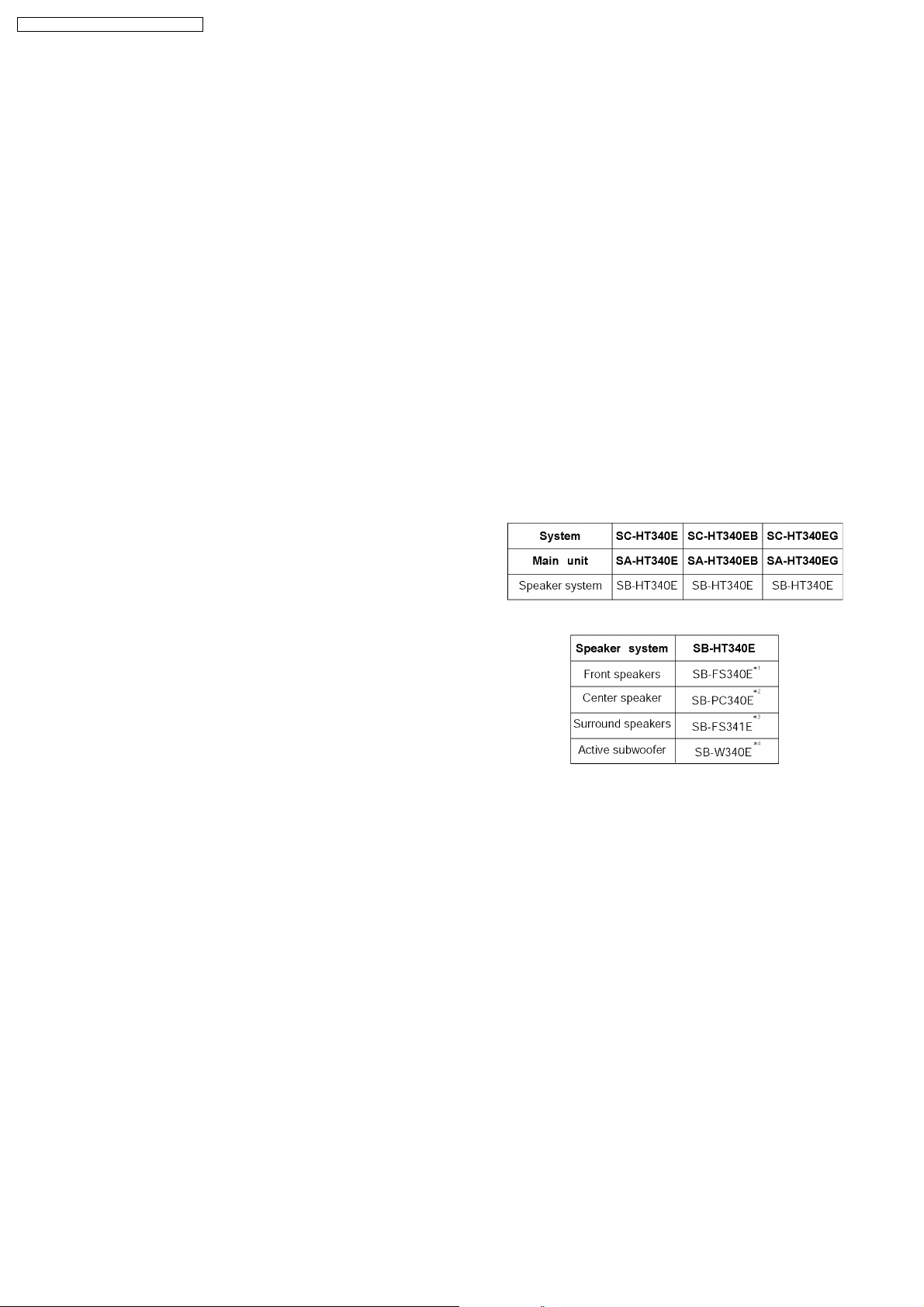
SA-HT340E
SA-HT340EB
SA-HT340EG
Colour
(S).......................Silver Type
Specifications
lGeneral
Power Source:
E/ EG areas:
EB area:
Power consumption:
Dimensions (W×H×D): 430×60×342 mm
Mass: 3kg
lAmplifier section
RMS Output Power: Dolby Digital Mode
lTotal RMS Dolby Digital
mode Power:
At 1kHz and total harmonic of 10%
lFront: 55 W/ Channel (5Ω)
lCenter: 55 W/ Channel (5Ω)
lSurround: 55 W/ Channel (5Ω)
At 100Hz and total harmonic of 10%
lActive subwoofers: 55 W/ Channel (5Ω)
DIN Output Power: Dolby Digital Mode:
lTotal DIN Dolby Digital mode Power:
At 1kHz and total harmonic of 1%
lFront: 25 W/ Channel (5Ω)
lCenter: 25 W/ Channel (5Ω)
lSurround: 25 W/ Channel (5Ω)
C 230V, 50Hz
C 230V-240V, 50Hz
90 W
330 W
150 W
At 100Hz and total harmonic of 1%
lSubwoofer: 25 W/ Channel (5Ω)
lFM tuner section (FM)
Preset Memory:
Frequency Range: 87.5-108.00MHz
Sensitivity: 1.8µV (IHF)
S/N 26dB
Antenna Terminals:
lAM tuner section (AM/MW)
Frequency Range:
AM Sensitivity S/N 20dB at
999kHz:
lDisc section
Discs played (8 cm or 12 cm):
(1) DVD [DVD-Video, DivX(*6,7)]
(2) DVD-RAM [DVD-VR, MP3(*2,7), JPEG(*4,7), MPEG4(*5 ,7),
DivX(*6,7)]
(3) DVD-R [DVD-Video, DVD-VR, MP3(*2,7), JPEG(*4,7),
MPEG4(*5,7), DivX(*6,7)]
(4) DVD-R DL [DVD-Video, DVD-VR]
(5) DVD-RW [DVD-Video, DVD-VR, MP3(*2,7), JPEG(*4,7),
MPEG4(*5,7), DivX(*6,7)]
(6) +R/RW [Video]
FM 15 stations
AM/MW 15 stations
(50kHz step)
1.4µV
75Ω (unbalanced)
522-1629kHz (9kHz step)
560µV/m
© 2006 Panasonic AVC Networks Singapore Pte.
Ltd. All rights reserved. Unauthorized copying and
distribution is a violation of law.
V
Y
SA-HT340E / SA-HT340EB / SA-HT340EG
(7) +R DL [Video]
(8) CD, CD-R/RW [CD-DA, Video CD, SVCD(*1), MP3(*2,7),
WMA(*3,7), JPEG(*4,7), MPEG4(*5,7), DivX (*6,7), HighMAT
Level 2 (Audio and Image)]
*1 Conforming to IEC62107
*2 MPEG-1 Layer 3, MPEG-2 Layer 3
*3 Windows Media Audio Ver.9.0 L3
lNot compatible with Multiple Bit Rate (MBR)
*4 Exif Ver 2.1 JPEG Baseline files
lPicture resolution: between 160 x 120 and 6144 x 4096
pixels (Sub sampling is 4:0:0, 4:2:0, 4:2:2, 4:4:4). Extremely
long and narrow pictures may not be displayed.
*5 MPEG4 data recorded with Panasonic SD multi cameras or
DVD video recorders.
lConforming to SD VIDEO specifications (ASF standard)/
MPEG4 (Simple Profile) video system/G.726 audio system.
*6 Plays all versions of DivX® video (including DivX®6) with
standard playback of DivX® media files. Certified to the DivX
Home Theater Profile.
lGMC (Global Motion Compensation) is not supported.
*7 The total combined maximum number of recognizable audio,
picture and video contents and groups: 4000 audio, picture
and video contents and 400 groups.
Pick up:
Wavelength:
lCD: 785nm
lDVD: 662nm
Laser power:
lCD: CLASS 1M
lDVD: CLASS 1
Audio output (DISC):
Number of channels: 5.1 ch (FL, FR, C, SL, SR,
SW)
Audio performance:
Frequency response:
DVD (linear audio): 4 Hz-22 kHz (48 kHz sampling)
4 Hz-44 kHz (96 kHz sampling)
CD-Audio: 4 Hz-20 kHz
S/N ratio:
CD-Audio: 105 dB
Dynamic range:
DVD (linear audio):
95 dB
CD-Audio: 95 dB
Total harmonic distortion:
CD-Audio: 0.005 %
lVideo section
ideo system:
Signal system: PAL 625/50, PAL 525/60,
NTSC
Composite video output:
Output level: 1 Vp-p (75 Ω )
Terminal: Scart jack (1 system)
S-video output:
output level: 1 Vp-p (75 Ω)
C output level: PAL; 0.3Vp-p (75Ω )
NTSC; 0.286 Vp-p (75 Ω)
Terminal Scart jack (1 system)
RGB video output:
R output level: 0.7 Vp-p (75 Ω)
G output level: 0.7 Vp-p (75 Ω )
B output level: 0.7 Vp-p (75 Ω)
Terminal: Scart jack (1 system)
Power consumption in standby mode:
approx 1W
Note:
1. Specifications are subject to change without notice.
Mass and dimensions are approximate.
2. Total harmonic distortion is measured by the digital spectrum
analyzer.
Solder:
This model uses lead free solder (PbF).
Mechanism:
This model uses DL2SU (Single tray) mechanism.
Power Supply:
This model uses Switching Mode Power Supply (SMPS)
Module for power-up unit.
Refer to original service manual for *1, *2, *3, *4.
2
SA-HT340E / SA-HT340EB / SA-HT340EG
3
SA-HT340E / SA-HT340EB / SA-HT340EG
CONTENTS
Page Page
1 Safety Precautions 5
1.1. GENERAL GUIDELINES
1.2. Before Repair and Adjustment (Using SMPS)
1.3. Protection Circuitry
1.4. Caution for AC Cord
2 Prevention of Electro Static Discharge (ESD) to
Electrostatically Sensitive (ES) Devices
3 Precaution of Laser Diode
4 About Lead Free Solder (PbF)
4.1. Service caution based on legal restrictions
5 Handling Precaution s for Traverse Unit
5.1. Cautions to Be Taken in Handling the Optical Pickup Unit
5.2. Grounding for electrostatic breakdown prevention
6 Accessories
7 Operation Procedures
7.1. Remote Control Keys Operation
7.2. Main Unit Keys Operation
7.3. Connection Setup
7.4. Disc information
7.5. About DivX VOD Content
8 Self-Diagnosis and special mode setting
8.1. Service Mode Summary Table
8.2. Service Mode Table 1
8.3. DVD Self Diagnostic Function-Error Code
8.4. Sales Demonstration Lock Function
8.5. Service Precautions
9 Assembling and Disassembling
9.1. Disassembly Flow Chart
9.2. Main Components and P.C.B. Locations
9.3. Disassembly of Top Cabinet
9.4. Disassembly of the DVD Lid (When taking out disc
manually)
9.5. Disassembly of Front Panel Assembly
9.6. Disassembly of FL P.C.B. & Volume P.C.B.
9.7. Disassembly of DVD Mechanism Unit
9.8. Disassembly of DVD Module P.C.B.
9.9. Disassembly of Rear panel
9.10. Disassembly of SMPS Module P.C.B.
9.11. Disassembly of Main P.C.B. & Tuner Extent P.C.B.
9.12. Disassembly of Digital Amp IC
10 Service Position
10.1. Servicing position of the DVD Module P.C.B.
10.2. Servicing position of the Main P.C.B.
10.3. Servicing position of the SMPS Module P.C.B.
11 Assembly and disassemb ly of Mechanism Unit
5
5
5
6
7
8
9
9
10
10
10
12
13
13
14
15
16
18
19
19
19
24
26
27
28
29
29
30
30
31
31
32
32
33
33
33
33
34
34
34
34
11.1. Disassembly Procedure
12 Measurements and Adjustments
12.1. Service Tools and Equipment
12.2. Important points in adjustment
12.3. Storing and handling of test discs
12.4. Optical adjustment
13 Abbreviati ons
14 Voltage and Waveform Chart
14.1. DVD Module P.C.B.
14.2. Main P.C.B.
14.3. FL P.C.B. & Tray Loading P.C.B.
14.4. SMPS Module P.C.B.
14.5. Waveform Chart
15 Illustration of IC's, Transistors and Diodes
16 Wiring Connection Diagram
17 Block Diagram
18 Schematic Notes
19 Schematic Diagram
19.1. (A) DVD Module (DV3.2) Circuit
19.2. (B) Main/FL/Volume/Tray Loading/Tuner Extent Circuit
20 Printed Circuit Board
20.1. (A) DVD Module P.C.B.
20.2. (B) Main/Power P.C.B.
20.3. (C) FL, Volume, Tuner Extent, & Tray Loading P.C.B.
21 Basic Troubleshooting Guide
21.1. Basic Troubleshooting Guide for Traverse Unit (DVD
Module P.C.B.)
21.2. Troubleshooting Guide for Power section (Power circuit)
22 Overall Block (HT340)
22.1. HT340 DVD Unit Block
22.2. HT340 Block (Analog Signal : DVD 5.1ch Play Back
Mode)
22.3. HT340 Block (Analog Signal : 2ch Analog Input Mode)
22.4. HT340 Power Supply Block
22.5. HT340 Power (Main) Block
23 Terminal Function of ICs
23.1. IC2018 (C2CBYY000194): System Control
Microprocessor IC
24 Exploded Views
24.1. Cabinet Parts Location
24.2. Packaging
25 Replacement Parts List
25.1. Component Parts List
35
35
41
41
41
41
42
43
45
45
46
47
47
48
49
51
53
59
61
61
65
71
71
72
73
75
75
75
76
77
78
79
80
81
82
82
83
83
85
86
87
4
SA-HT340E / SA-HT340EB / SA-HT340EG
1 Safety Precautions
1.1. GENERAL GUIDELINES
1. When servicing, observe the original lead dress. If a short circuit is found, replace all parts which have been overheated or
damaged by the short circuit.
2. After servicing, see to it that all the protective devices such as insulation barriers, insulation papers shields are properly
installed.
3. After servicing, carry out the following leakage current checks to prevent the customer from being exposed to shock hazards.
1.1.1. LEAKAGE CURRENT COLD CHECK
1. Unplug the AC cord and connect a jumper between the two prongs on the plug.
2. Measure the resistance value, with an ohmmeter, between the jumpered AC plug and each exposed metallic cabinet part on
the equipment such as screwheads, connectors, control shafts, etc. When the exposed metallic part has a return path to the
chassis, the reading should be between 1MΩ and 5.2MΩ.
When the exposed metal does not have a return path to the chassis, the reading must be
.
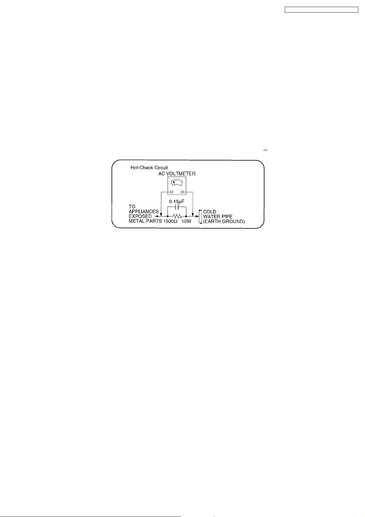
Figure 1
1.1.2. LEAKAGE CURRENT HOT CHECK (See Figure 1.)
1. Plug the AC cord directly into the AC outlet. Do not use an isolation transformer for this check.
2. Connect a 1.5kΩ, 10 watts resistor, in parallel with a 0.15µF capacitors, between each exposed metallic part on the set and a
good earth ground such as a water pipe, as shown in Figure 1.
3. Use an AC voltmeter, with 1000 ohms/volt or more sensitivity, to measure the potential across the resistor.
4. Check each exposed metallic part, and measure the voltage at each point.
5. Reverse the AC plug in the AC outlet and repeat each of the above measurements.
6. The potential at any point should not exceed 0.75 volts RMS. A leakage current tester (Simpson Model 229 or equivalent) may
be used to make the hot checks, leakage current must not exceed 1/2 milliamp. In case a measurement is outside of the limits
specified, there is a possibility of a shock hazard, and the equipment should be repaired and rechecked before it is returned to
the customer.
1.2. Before Repair and Adjustment (Using SMPS)
This model uses Switching Mode Power Supply (SMPS) Module to provide the neccessary voltages for the unit.
DO NOT SHORT-CIRCUIT DIRECTLY (with a screwdriver blade, for instance), as this may destroy solid state devices.
After repairs are completed, restore power gradually using a variac, to avoid overcurrent.
Current consumption at AC 230 V, 50 Hz in NO SIGNAL mode volume minimal should be ~ 650 mA. (For E/EG)
Current consumption at AC 230V~240V, 50 Hz in NO SIGNAL mode volume minimal should be ~ 650 mA. (For EB)
1.3. Protection Circuitry
The protection circuitry may have operated if either of the following conditions are noticed:
· No sound is heard when the power is turned on.
· Sound stops during a performance.
The function of this circuitry is to prevent circuitry damage if, for example, the positive and negative speaker connection wires are
“shorted”, or if speaker systems with an impedance less than the indicated rated impedance of the amplifier are used.
5
SA-HT340E / SA-HT340EB / SA-HT340EG
If this occurs, follow the procedure outlines below:
1. Turn off the power.
2. Determine the cause of the problem and correct it.
3. Turn on the power once again after one minute.
Note:
When the protection circuitry functions, the unit will not operate unless the power is first turned off and then on again.
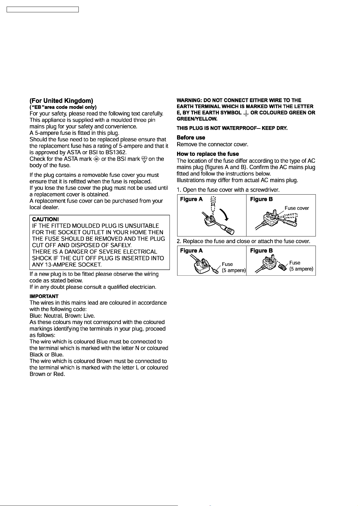
1.4. Caution for AC Cord
6
SA-HT340E / SA-HT340EB / SA-HT340EG
2 Prevention of Electro Static Discharge (ESD) to
Electrostatically Sensitive (ES) Devices
Some semiconductor (solid state) devices can be damaged easily by static electricity. Such components commonly are called
Electrostatically Sensitive (ES) Devices. Examples of typical ES devices are integrated circuits and some field-effect transistors and
semiconductor "chip" components. The following techniques should be used to help reduce the incidence of component damage
caused by electro static discharge (ESD).
1. Immediately before handling any semiconductor component or semiconductor-equipped assembly, drain off any ESD on your
body by touching a known earth ground. Alternatively, obtain and wear a commercially available discharging ESD wrist strap,
which should be removed for potential shock reasons prior to applyin g power to the unit under test.
2. After removing an electrical assembly equipped with ES devices, place the assembly on a conductive surface such as
aluminum foil, to prevent electrostatic charge buildup or exposure of the assembly.
3. Use only a grounded-tip soldering iron to solder or unsolder ES devices.
4. Use only an anti-static solder removal device. Some solder removal devices not classified as "anti-static (ESD protected)" can
generate electrical charge sufficient to damage ES devices.
5. Do not use freon-propelled chemicals. These can generate electrical charges sufficient to damage ES devices.
6. Do not remove a replacement ES device from its protective package until immediately before you are ready to install it. (Most
replacement ES devices are packaged with leads electrically shorted together by conductive foam, aluminum foil or comparable
conductive material).
7. Immediately before removing the protective material from the leads of a replacement ES device, touch the protective material
to the chassis or circuit assembly into which the device will be installed.
Caution
Be sure no power is applied to the chassis or circuit, and observe all other safety precautions.
8. Minimize bodily motions when handling unpackaged replacement ES devices. (Otherwise harmless motion such as the
brushing together of your clothes fabric or the lifting of your foot from a carpeted floor can generate static electricity (ESD)
sufficient to damage an ES device).
7
SA-HT340E / SA-HT340EB / SA-HT340EG
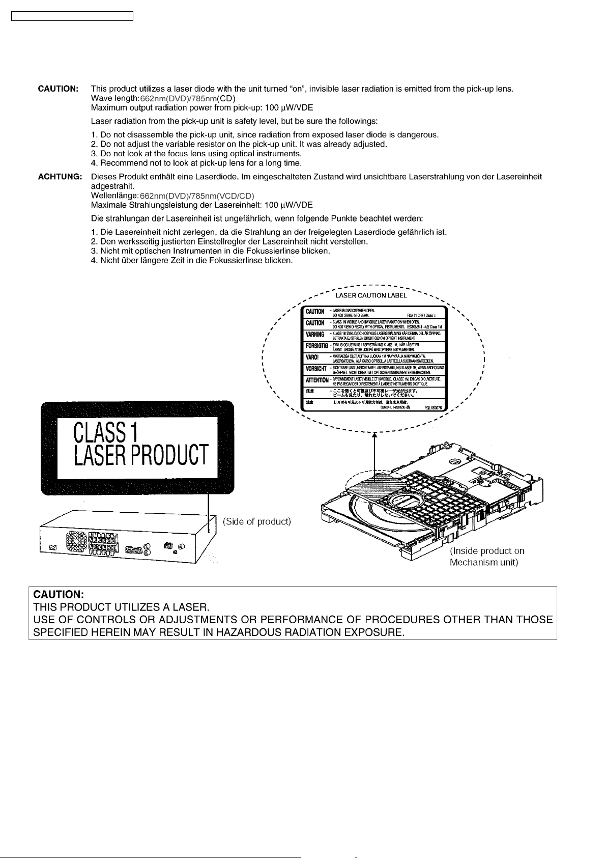
3 Precaution of Laser Diode
8
SA-HT340E / SA-HT340EB / SA-HT340EG
4 About Lead Free Solder (PbF)
4.1. Service caution based on legal restrictions
4.1.1. General description about Lead Free Solder (PbF)
The lead free solder has been used in the mounting process of all electrical components on the printed circuit boards used for this
equipment in considering the globally environmental conservation.
The normal solder is the alloy of tin (Sn) and lead (Pb). On the other hand, the lead free solder is the alloy mainly consists of tin
(Sn), silver (Ag) and Copper (Cu), and the melting point of the lead free solder is higher approx.30 degrees C (86°F) more than that
of the normal solder.
Definition of PCB Lead Free Solder being used
The letter of “PbF” is printed either foil side or components side on the PCB using the lead free solder.
(See right figure)
Service caution for repair work using Lead Free Solder (PbF)
· The lead free solder has to be used when repairing the equipment for which the lead free solder is used.
(Definition: The letter of “PbF” is printed on the PCB using the lead free solder.)
· To put lead free solder, it should be well molten and mixed with the original lead free solder.
· Remove the remaining lead free solder on the PCB cleanly for soldering of the new IC.
· Since the melting point of the lead free solder is higher than that of the normal lead solder, it takes the longer time to melt
the lead free solder.
· Use the soldering iron (more than 70W) equipped with the temperature control after setting the temperature at 350±30
degrees C (662±86°F).
Recommended Lead Free Solder (Service Parts Route.)
· The following 3 types of lead free solder are available through the service parts route.
RFKZ03D01K-----------(0.3mm 100g Reel)
RFKZ06D01K-----------(0.6mm 100g Reel)
RFKZ10D01K-----------(1.0mm 100g Reel)
Note
* Ingredient: tin (Sn), 96.5%, silver (Ag) 3.0%, Copper (Cu) 0.5%, Cobalt (Co) / Germanium (Ge) 0.1 to 0.3%
9
SA-HT340E / SA-HT340EB / SA-HT340EG
5 Handling Precautions for Traverse Unit
The laser diode in the optical pickup unit may break down due to static electricity of clothes or human body. Special care must be
taken avoid caution to electrostatic breakdown when servicing and handlin g the laser diode.
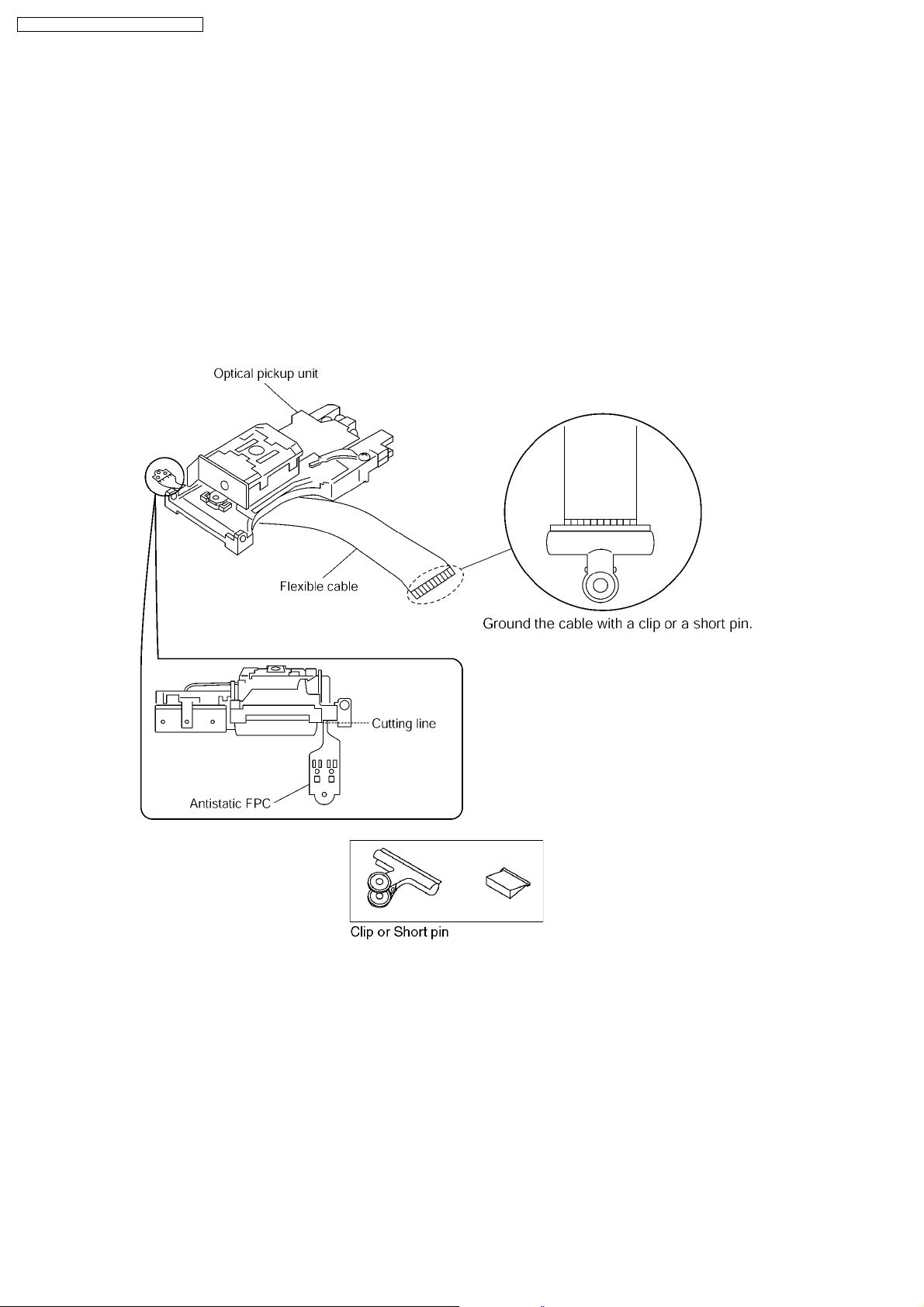
5.1. Cautions to Be Taken in Handling the Optical Pickup Unit
The laser diode in the optical pickup unit may be damaged due to electrostatic discharge generating from clothes or human body.
Special care must be taken avoid caution to electrostatic discharge damage when servicing the laser diode.
1. Do not give a considerable shock to the optical pickup unit as it has an extremely high-precise structure.
2. To prevent the laser diode from the electrostatic discharge damage, the flexible cable of the optical pickup unit removed should
be short-circuited with a short pin or a clip.
3. The flexible cable may be cut off if an excessive force is applied to it. Use caution when handling the flexible cable.
4. The antistatic FPC is connected to the new optical pickup unit. After replacing the optical pickup unit and connecting the flexible
cable, cut off the antistatic FPC.
5.2. Grounding for electrostatic breakdown prevention
Some devices such as the DVD player use the optical pickup (laser diode) and the optical pickup will be damaged by static
electricity in the working environment. Proceed servicing works under the working environment where grounding works is
completed.
5.2.1. Worktable grounding
1. Put a conductive material (sheet) or iron sheet on the area where the optical pickup is placed, and ground the sheet.
5.2.2. Human body grounding
1. Use the anti-static wrist strap to discharge the static electricity form your body.
10

SA-HT340E / SA-HT340EB / SA-HT340EG
11
SA-HT340E / SA-HT340EB / SA-HT340EG
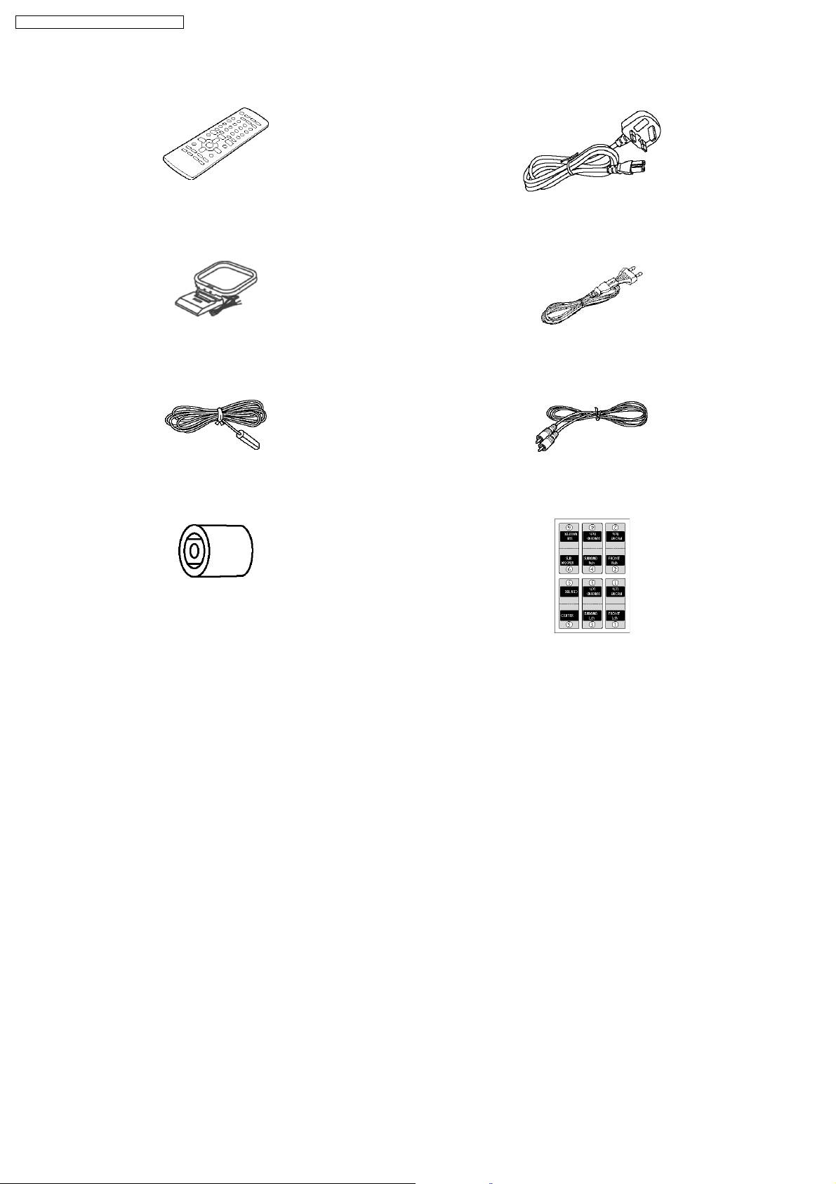
6 Accessories
Remote control
AM loop antenna
FM indoor antenna
Din adaptor
(For EB area)
AC cord
(For EB area)
AC cord
(For E, EG areas)
Video cable
(For E, EG areas)
Speaker label
12
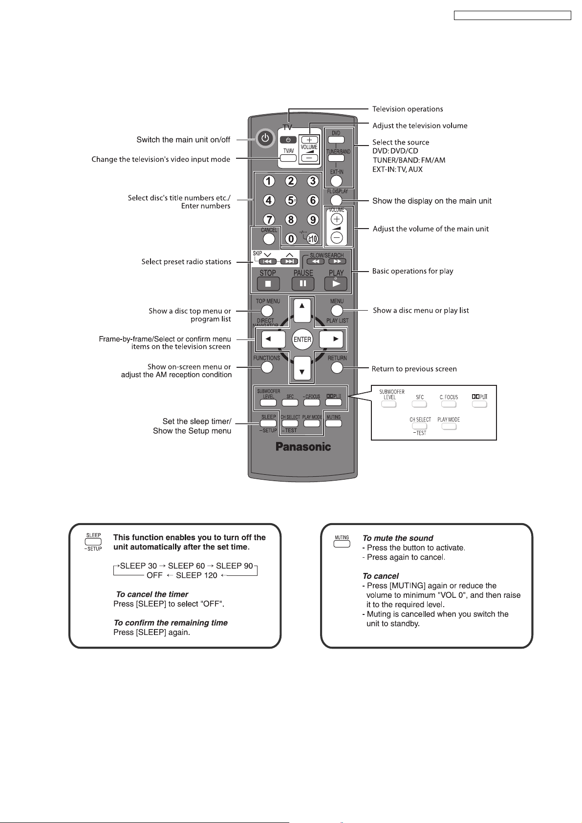
7 Operation Procedures
7.1. Remote Control Keys Operation
SA-HT340E / SA-HT340EB / SA-HT340EG
13
Disc playback
SA-HT340E / SA-HT340EB / SA-HT340EG
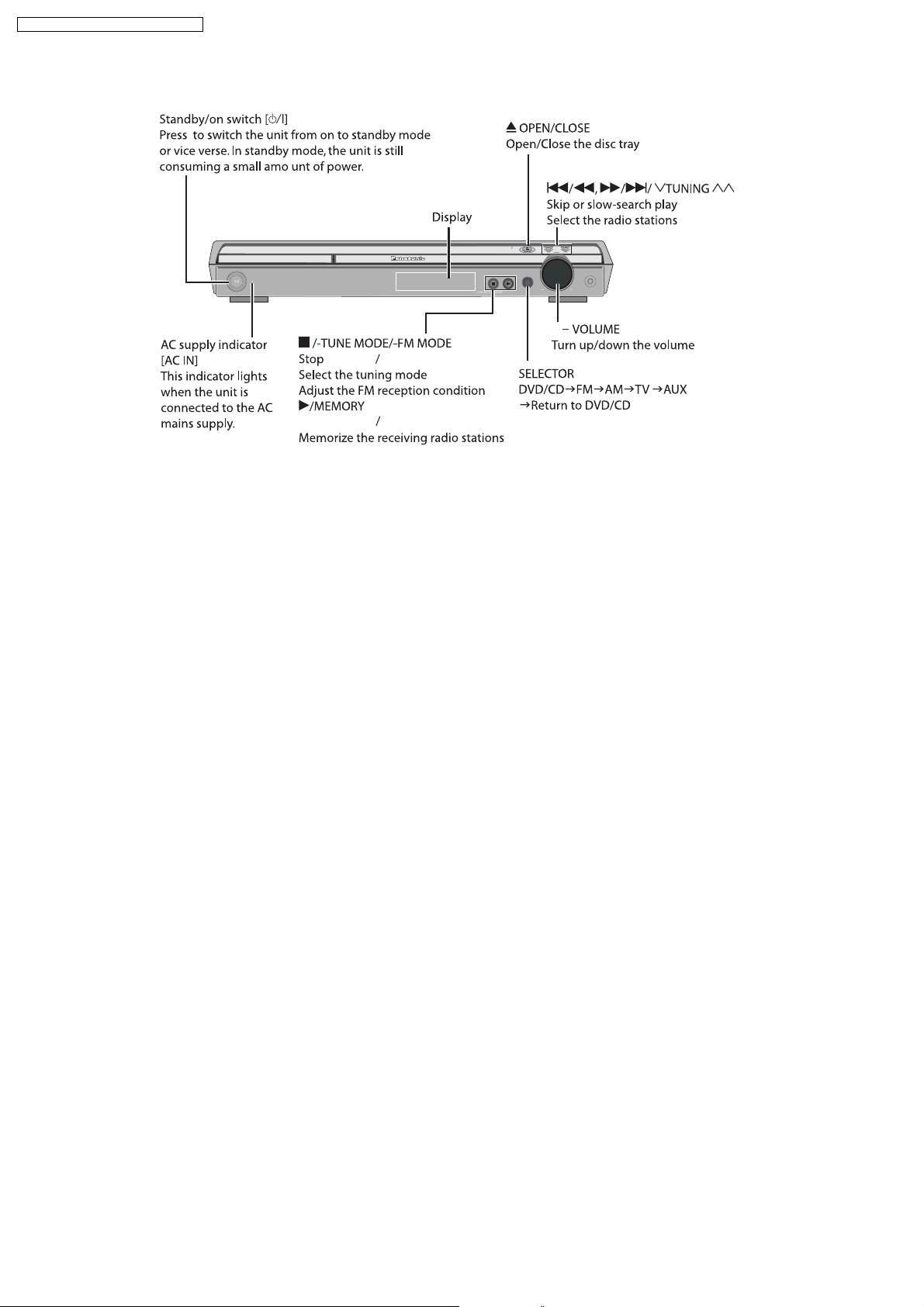
7.2. Main Unit Keys Operation
OPENCLOSE
AC IN
MEMOR Y
SELECTOR
TUNING
VOLUME
+,
playback
Disc playback
14
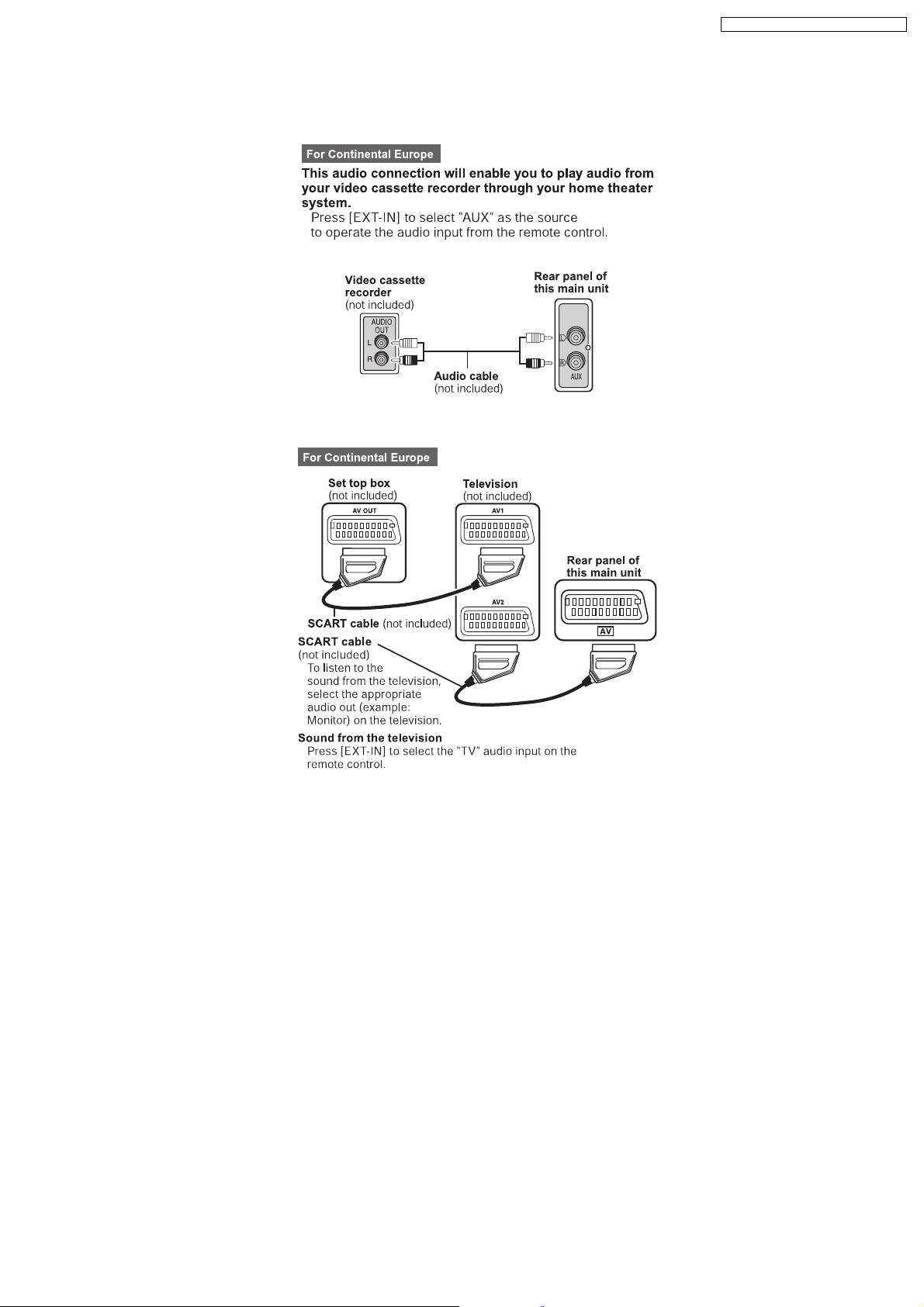
7.3. Connection Setup
7.3.1. Audio Connection for VCR/TV
7.3.2. Scart Connection for Set Top Box/VCR/TV
SA-HT340E / SA-HT340EB / SA-HT340EG
15
SA-HT340E / SA-HT340EB / SA-HT340EG
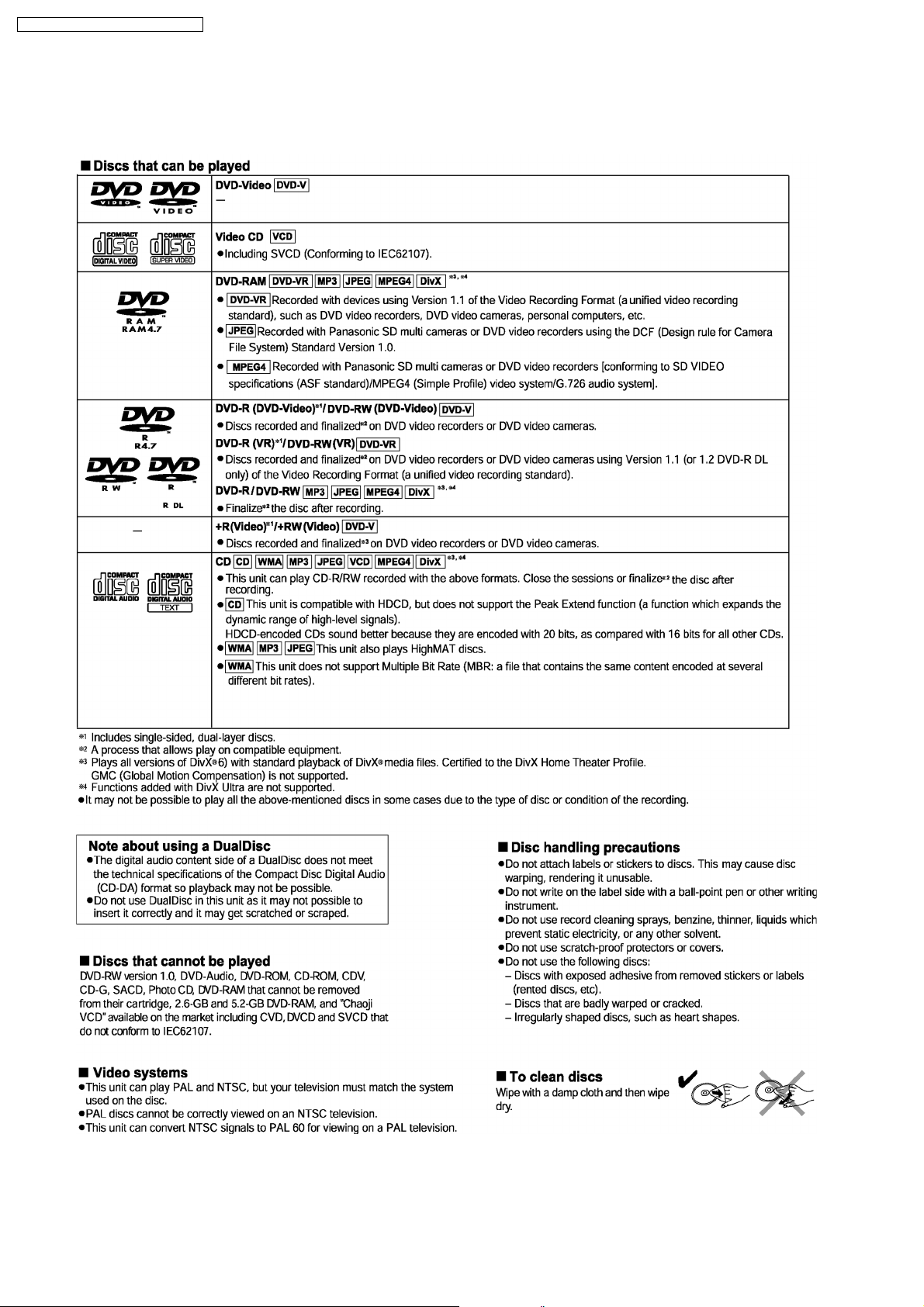
7.4. Disc information
7.4.1. Disc playability (Media)
16
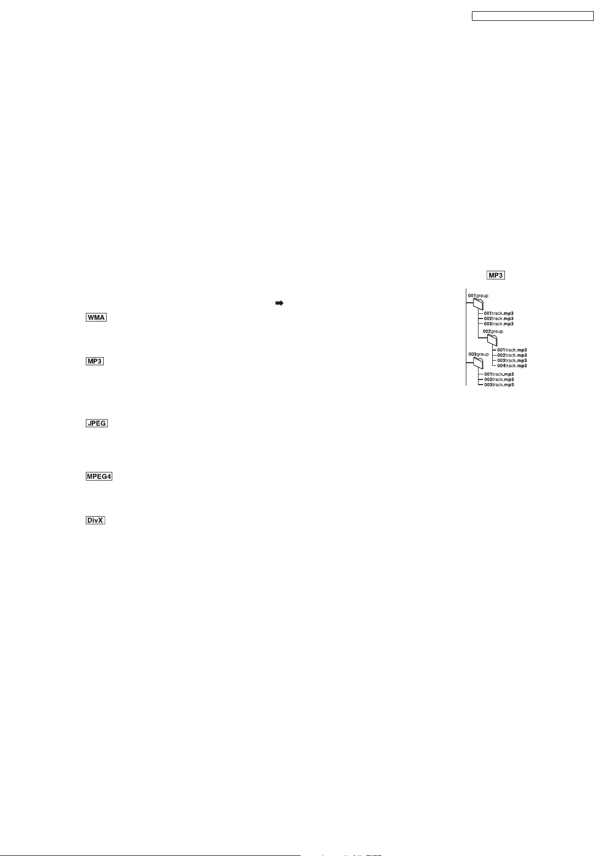
7.4.2. File Extension Type Support (WMA/MP3/JPEG/MPEG4/DivX)
Tips for making data discs
When there a re more th an eight g roups , the eigh th group o nwards w ill be di splayed on one ver tic al line in t he menu
screen.
There may be differences in the display order on the menu screen and computer sc reen.
This unit cannot play les recorded using packet write.
DVD-RAM
Discs must conform to UDF 2.0.
DVD-R/RW
Discs must conform to UDF bridge (UDF 1.02/ISO9660).
This unit does not support multi-session. Only the default session is played.
CD-R/RW
Discs must conform to ISO9660 level 1 or 2 (except for extended formats).
This un i t su p p o rts mul t i -s e s s io n b u t if t h er e ar e ma ny s es s i on s i t t a ke s mo r e ti m e fo r p lay t o st a rt. Keep th e n um b e r of
sessions to a minimum to avoid this.
Naming folders and files
fi
SA-HT340E / SA-HT340EB / SA-HT340EG
Files are treated as contents and folders are treated as groups on this unit.
At the time of recording, pre x folder and le names. This should be with numbers that have
fi fi
Example:
root
an equal number of digits, and should be done in the order you want to play them (this may
not work at times). Files must have the extension ( see below).
(Extension: “.WMA” or “.wma”)
Compatible compression rate: between 48 kbps and 320 kbps.
You canno t play WMA les that are copy pr otected.
fi
This unit does not support Multiple Bit Rate (MBR).
(Extension: “.MP3” or “.mp3”)
Compatible compression rate: between 32 kbps and 320 kbps.
This unit does not support ID3 tags.
Compatible sampling rates:
– DVD-RAM, DVD-R/RW: 11.02, 12, 22.05, 24, 44.1 and 48 kHz
– CD-R/RW: 8, 11.02, 12, 16, 22.05, 24, 32, 44.1 and 48 kHz
(Extension: “.JPG”, “.jpg”, “.JPEG” or “.jpeg”)
JPEG les taken on a digital camera that conform to DCF Standard (Design rule for Camera File system) Version 1.0 are
fi
displayed. Files that have been altered, edited or saved with computer picture editing software may not be displayed.
This unit cannot display moving pictures, MOTION JPEG and other such formats, and still pictures other than JPEG
(Example: TIFF), or play pictures with attached audio.
(Extension: “.ASF” or “.asf”)
You can play MPEG4 data [ conforming to S D VIDEO spec i c ations (ASF stand ard)/MPEG4 (S imple Pro le) video
fi
fi
system/G.726 audio system] recorded with Panasonic SD multi cameras or DVD video recorders with this unit.
The recording date may differ from that of the actual date.
(Extension: “.DIVX”, “.divx”, “.AVI” or “.avi”)
You can play all vers ions of DivX
system] with standard playback of DivX® media les. Functions added with DivX Ultra are not supported.
®
video (including DivX®6) [Di vX video system/ MP3, Dolby Digit al or MPEG audio
fi
G MC (Global Motion Compensation) is not supported.
DivX les greater than 2 GB or have no index may not be played properly on this unit.
fi
This unit supports all resolutions up to maximum of 720 x 480 (NTSC)/720 x 576 (PAL).
You can select up to eight types of audio and subtitles on this unit.
17
SA-HT340E / SA-HT340EB / SA-HT340EG
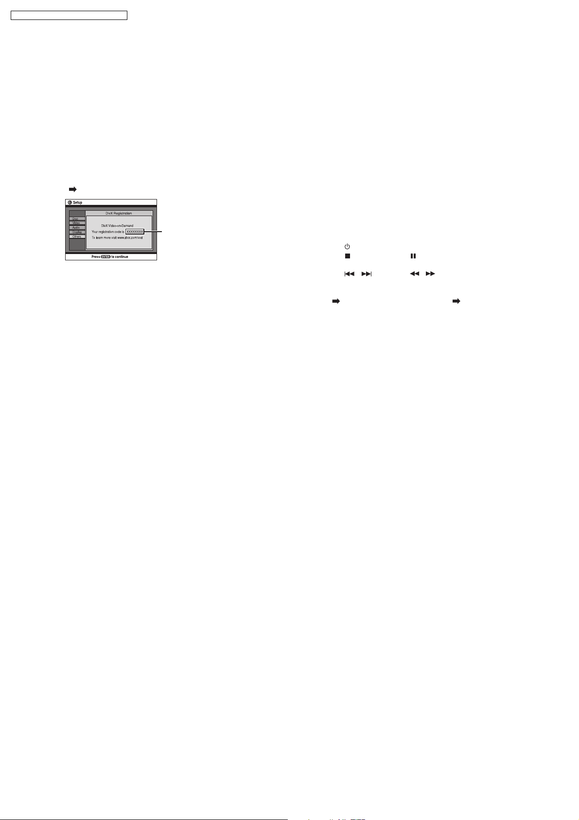
7.5. About DivX VOD Content
About DivX VOD content
DivX Video-on-Demand (VOD) conten t is encrypte d for
copyright protection. In order to play DivX VOD content on
this unit, you rst need to register the unit.
Follow th e online instru ctions ffior purchasing DivX VOD
conten t to enter the un it’s regist ration c ode and reg ister
the unit. For more information about DivX VOD, visit
www.divx.com/vod.
Display the unit’s registration code
( Refer to OI page 23, “DivX Registration” in “Others” tab)
8 alphanumeric
characters
We recommend that you make a note of this code for
future reference.
After playing DivX VOD content for the
another registration code is then displayed in “DivX
Registration”. Do not use this registration code to
purchase DivX VOD content. If you use this code
to purchase DivX VOD content, and then play the
content on this unit, you will no longer be able to play
any content that you purchased using the previous
code.
rst time,
fi
If you purchase DivX VOD content using a
registration code different from this unit’s code, you
will not be able to play this content. (“Authorization
Error” is displayed.)
Regarding DivX content that can only be
played a set number of times
Some DivX VOD content can only be played a set
number of times. When you play this content, the
remaining number of plays is displayed. You cannot
play this content when the number of remaining plays
is zero. (“Rented Movie Expired” or “Rental Expired” is
displayed.)
When playing this content
The number of remaining plays is reduced by one if
– you press [ ] or press and hold [–SETUP].
– you press [ , STOP]. (Press [ , PAUSE] to pause
play.)
– you press [, ] (skip) or [, ] (slow/search)
etc. and arrive at another content or the start of the
content being played.
Resume ( OI page 15, Stop) and Marker ( OI page 20,
Play Menu) functions do not work.
18
SA-HT340E / SA-HT340EB / SA-HT340EG
8 Self-Diagnosis and special mode setting
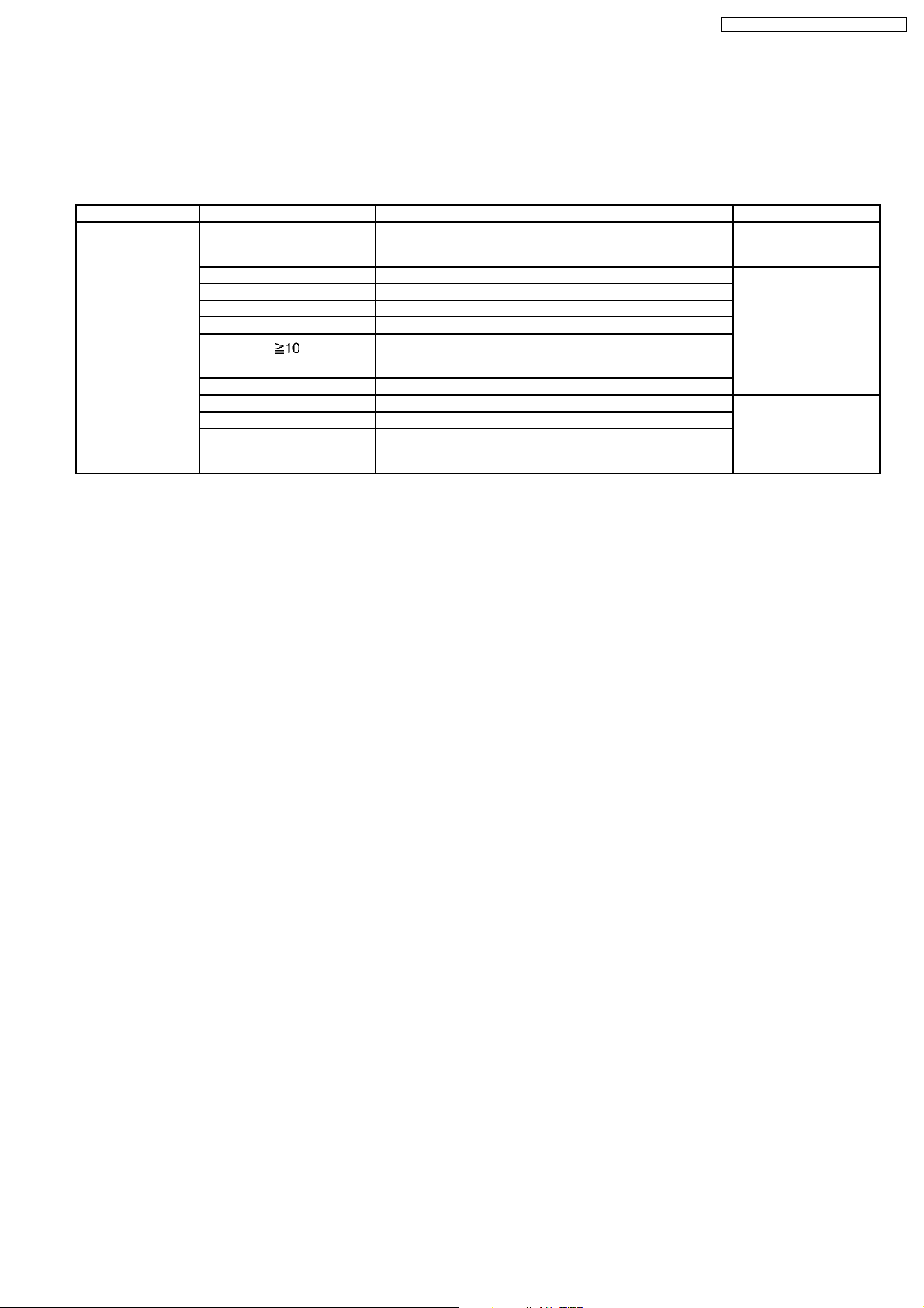
8.1. Service Mode Summary Table
The service modes can be activated by pressing various button combination on the player and remote control unit.
Below is the summary of major checking:
Player buttons Remote control unit buttons Application Note
STOP 0 Error code display (Refer to the section,
5 Jitter checking (Refer to the section “8.2
6 Region display and mode
7 Micro-processor firmware version check
8 DVD module firmware version check.
Initialization of the player (factory setting is restored.)
Used after replacement of micro-computer, FLASH ROM IC,
EEPROM and HDMI module.
ENTER DVD module reset (During initialisation)
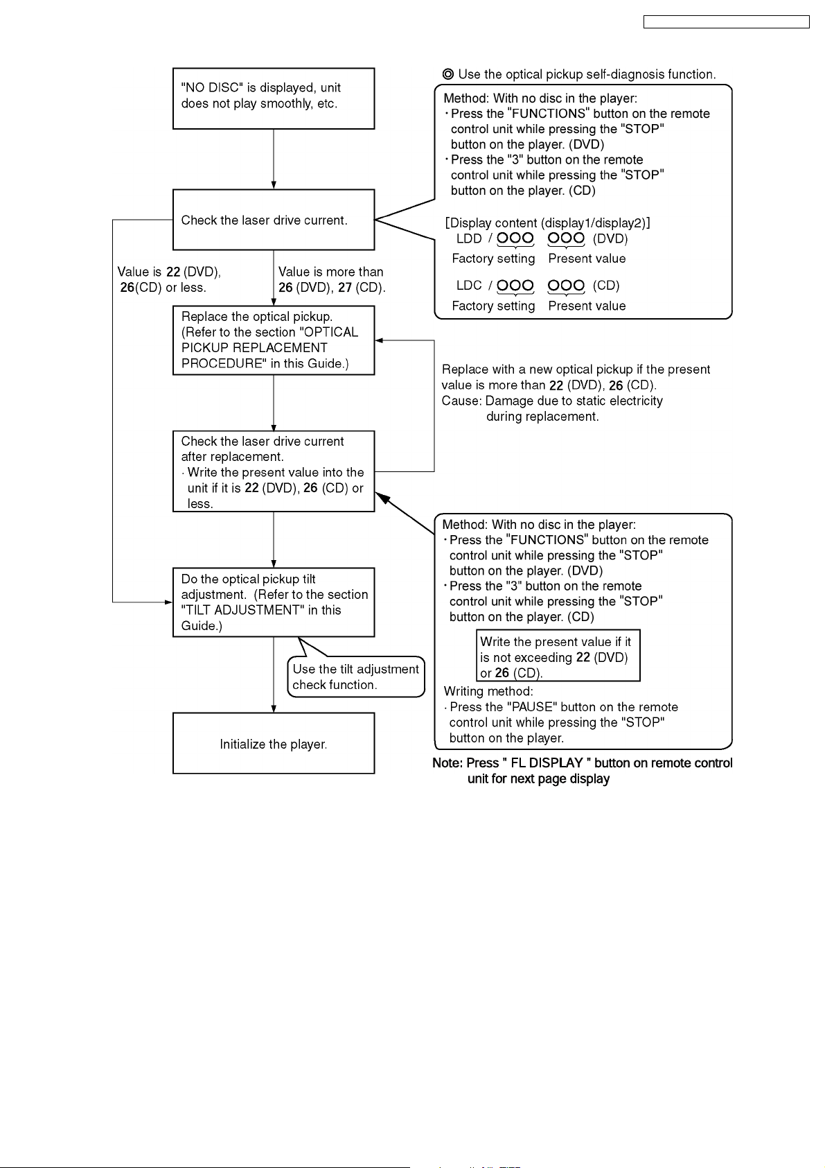
FUNCTIONS DVD laser drive current check (Refer to the item “8.2.1.
3 CD laser drive current check
PAUSE Writing of laser drive current value after replacement of optical
pickup (Do use this function only when optical pickup is
replaced.)
“8.3 DVD Self Diagnostic
Function-Error Code”).
Service Mode Table 1”
for more information).
Optical Pick-up SelfDiagnosis”).
8.2. Service Mode Table 1
By pressing various button combin ations on the player and remote control unit can activate the various service modes for checking.
Special Note:
Due to the limitations of the no. characters that can be shown on FL Display, the “FL Display” button on the remote control uni
is used to show the following page. (Display 1/Display 2).
19
SA-HT340E / SA-HT340EB / SA-HT340EG
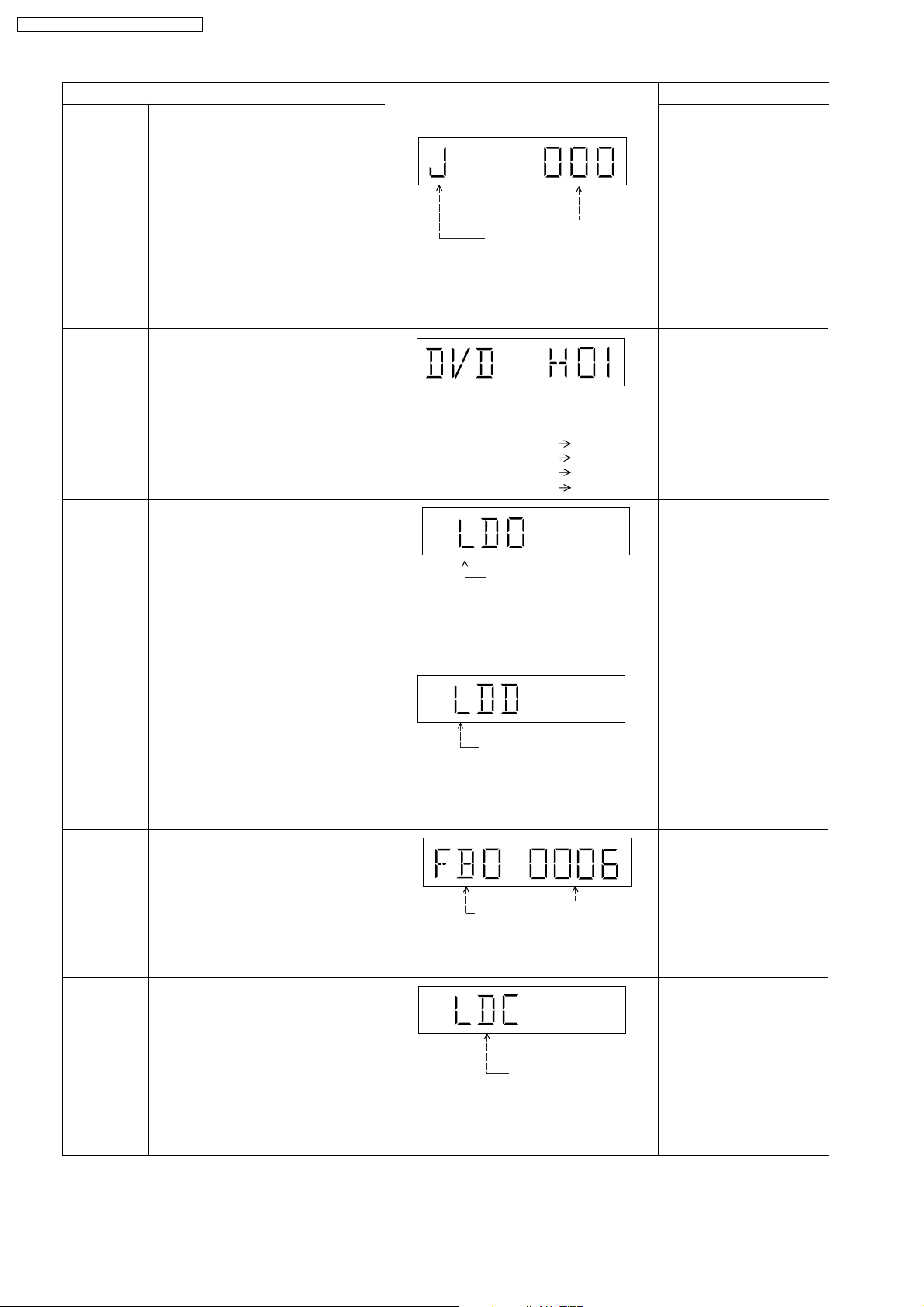
Mode Name
Jitter check
Error code
check
Initial setting
of laser drive
current
DVD laser
drive current
measurement
ADSC internal
RAM data
check
CD laser drive
current
measurement
Item
Description
Jitter check
Jitter rate is measured and displayed.
Measurement is repeatedly done in
the cycle of one second. Read error
counter starts from zero upon mode
setting. When target block data failed
to be read out, the counter advances
by one increment. When the failure is
caused by minor error, it may be
corrected when retried to enable
successful reading. In this case, the
counter advances by one. When the
error persists even after retry, the
counter may jump by two or more.
Error code check
The latest error code stored in the
EEPROM IC is displayed.
Initial setting of laser drive current.
Initial current value for each of DVD
laser and CD laser is separately saved
in the EEPROM IC.
DVD laser drive current measurement
·DVD laser drive current is measured
and the result is displayed together
with the initial value stored in the
EEPROM IC.
After the measurement, DVD laser
emission is kept on. It is turned off
when POWER key is switched off. (It
is also turned off when POWER button
on the player is switched off.)
ADSC internal RAM data check
·ADSC internal RAM data is read out
and displayed.
CD laser drive current measurement
CD laser drive current is measured
and the result is displayed together
with the initial value stored in the
EEPROM IC.
After the measurement, CD laser
emission is kept on. It is turned off
when POWER key is switched off. (It
is also turned off when POWER button
on the player is switched off.)
FL Display
Jitter rate
Jitter check mode
Jitter rate is shown in decimal notation to
one place of decimal.
Focus drive value is shown in hexadecimal
notation.
Error code (play_err) is expressed in the
following convention.
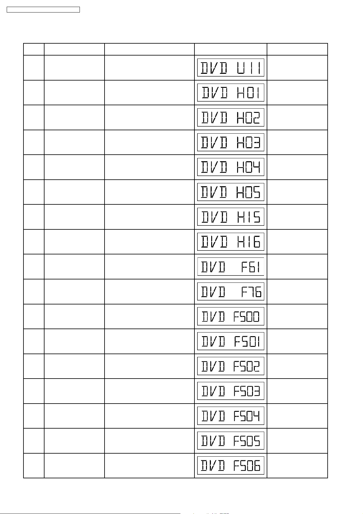
Error code = 0 x DAXX is expressed: DVDnn UXX
Error code = 0 x DBXX is expressed: DVDnn HXX
Error code = 0 x DXXX is expressed: DVDnn FXXX
Error code = 0 x 0000 is expressed: DVDnn F--* "xx" denotes the error code
Laser current measurement
mode
The value denotes the current in decimal
notation. The above example shows the
initial current is 34mA and 28mA for DVD
laser and CD laser respectively when the
laser is switched on.
DVD laser current
measurement mode
The value denotes the current in decimal
notation.
The above example shows the initial current
is 34mA and the measured value is 32mA.
Address
RAM data for
specified address
The value is shown in hexadecimal
notation. The above example shows the
data in ADSC address OFAh is 6901h.
CD laser current
measurement mode
The value denotes the current in decimal
notation.
The above example shows the initial current
is 28mA and the measured value is 26mA.
Key Operation
Front Key
In STOP (no disc) mode,
press STOP button on the
player, and "5" button on
the remote control unit.
Press STOP or OPEN
button to exit.
Press "FL Display" on
remote control unit for next
page (FL Display).
In STOP (no disc) mode,
press STOP button on the
player, and "0" button on the
remote control unit. * With
pointing of cursor up and
down on display.
Cancelled automatically
5 seconds later.
To exit, press [POWER]
button on main unit or
remote control.
In STOP (no disc) mode,
press STOP button on the
player, and PAUSE button
on the remote control unit.
Cancelled automatically
5 seconds later.
Press "FL Display" on
remote control unit for next
page (FL Display) on values
of laser drive current.
In STOP (no disc) mode,
press STOP button on the
player, and FUNCTIONS
button on the remote
control unit.
Cancelled automatically
5 seconds later.
Press "FL Display" on
remote control unit for next
page (FL Display) on values
of dvd drive current.
In STOP (no disc) mode,
press STOP button on the
player, and "1" button on
the remote control unit.
Press STOP or PLAY
button.
In STOP (no disc) mode,
press STOP button on the
player, and "3" button on
the remote control unit.
Cancelled automatically
5 seconds later.
Press "FL Display" on
remote control unit for next
page. (FL Display)
20
SA-HT340E / SA-HT340EB / SA-HT340EG
Micro-processor
firmware version
display &
EEPROM
checksum
display.
Initialization
Region display
DVD module
firmware
version display
Communication
error display
DVD Module
Reset
Item
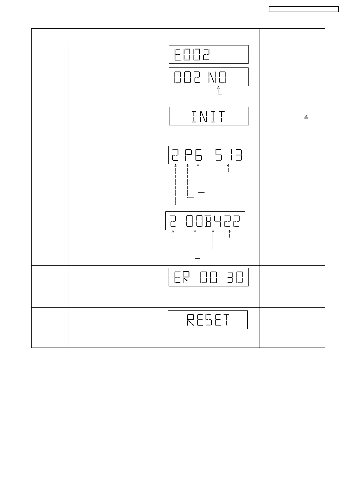
DescriptionMode Name
Micro-processor firmware version
display & EEPROM checksum display.
EEPROM checksum is only available
due to existence of EEPROM IC.
(NO: NO EEPROM IC)
If EEPROM IC is present, the checksum
value will be displayed. It displays as
"NG" if the EEPROM IC installed is not
working properly.
Initialization
User settings are cancelled and player
is initialized to factory setting.
Region display & mode
DVD module firmware version is
displayed on the FL Display.
The firmware version can be updated
using recovery disc.
Displays frequency of communication
errors between system control IC and
mechanism control IC during DVD
module.
To reset DVD Module.
This process is used when the DVD
module or flash ROM IC is replaced
with a new one.
N: noPAL / P: PAL
Region No.
Region
FL Display
Existence of
EEPROM
N: NTSC / 6: PAL60
Destination
System controller
generation
Panel
controller
jumper
information
System
controller
version
Key Operation
Front Key
In STOP (no disc)
mode, press STOP button
on the player, and "7"
button on the remote
control unit.
Cancelled automatically
5 seconds later.
Press "FL Display" button on
remote control unit for next
page. (FL Display)
In STOP (no disc)
mode, press STOP button
on the player , and
10
button on the remote
control unit.
Cancelled automatically
5 seconds later.
In STOP (no disc)
mode, press STOP button
on the player, and "6"
button on the remote
control unit.
Cancelled automatically
5 seconds later.
In STOP (no disc)
mode, press STOP button
on the player, and "8"
button on the remote
control unit.
Cancelled automatically
5 seconds later.
In STOP (no disc)
mode, press STOP button
on the player, and "MENU"
button on the remote
control unit.
Cancelled automatically
5 seconds later.
While in initialization
mode, press & hold STOP
button on player, follow by
"ENTER" button on the
remote control unit.
Cancelled automatically
5 seconds later.
21
SA-HT340E / SA-HT340EB / SA-HT340EG
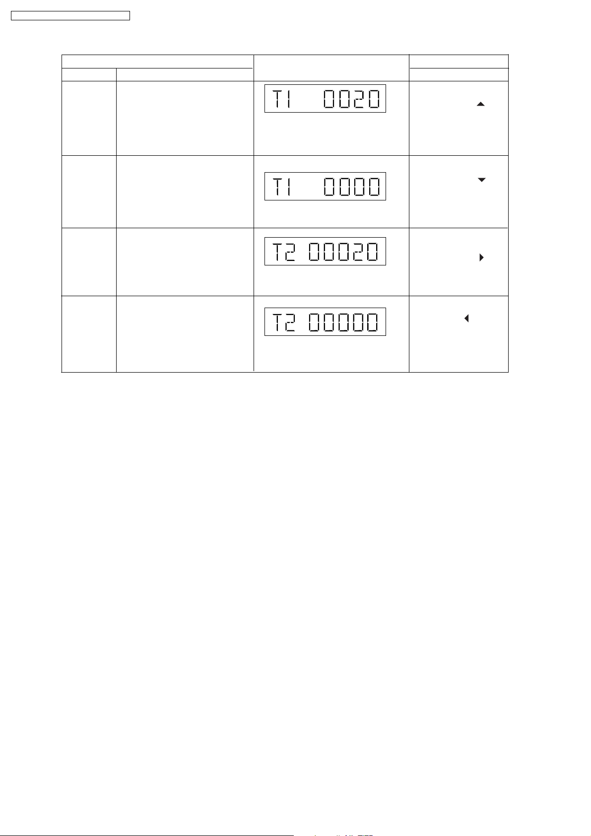
Mode Name
Timer 1 check
Timer 1 reset
Timer 2 check
Timer 2 reset
Item
Description
Timer 1 check
Laser operation timer is measured
separately for DVD laser and CD laser.
Press "FL Display" button for next
page of FL Display
Timer 1 reset
Laser operation timer of both DVD
laser and CD laser is reset all at once.
Timer 2 check
Spindle motor operation timer
Press "FL Display" button for next
page of FL Display
Timer 2 reset
Spindle motor operation timer
Press "FL Display" button for next
page of FL Display
FL Display
Shown to the left is DVD laser time, and to
the right is CD laser time.
Time is shown in 4 digits of decimal notation
in a unit of 10 hours.
"0000" will follow "9999".
Shown to the left is DVD laser time, and to
the right is CD laser time.
It will clear to "0000" upon reset.
Time is shown in 5 digits of decimal notation in
a unit of 10 hours.
"00000" will follow "99999".
Time is shown in 5 digits of decimal notation in
a unit of 10 hours.
It will be cleared to "00000" upon activating
this.
Key Operation
Front Key
In STOP (no disc)
mode, press STOP button
on the player, and " "
button on the remote
control unit.
Cancelled automatically
5 seconds later.
While displaying Timer 1
data, press STOP button
on the player, and " "
button on the remote
control unit.
Cancelled automatically
5 seconds later.
In STOP (no disc)
mode, press STOP button
on the player, and " "
button on the remote
control unit.
Cancelled automatically
5 seconds later.
While displaying Timer 2
data, press STOP button on
the player, and " " button
on the remote control unit.
Cancelled automatically
5 seconds later.
8.2.1. Optical Pick-up Self-Diagnosis
The optical pickup self-diagnosis function and tilt adjustment check function have been included in this unit. When repairing, use
the following procedure for effectiv e self-diagnosis and tilt adjustment. Be sure to use the self-diagnosis function before replacing
the optical pickup when "NO DISC" is displayed. As a guideline, you should replace the optical pickup when the value of the laser
drive current is more than 55.
Note:
Press the power button to turn on the power, and check the value within three minutes before the unit warms up. (Otherwise,
the result will be incorrect.)
22
SA-HT340E / SA-HT340EB / SA-HT340EG
23
SA-HT340E / SA-HT340EB / SA-HT340EG
8.3. DVD Self Diagnostic Function-Error Code
Error
Code
U11 Focus servo error Focus coil NG (OPU unit abnormal) Press [ n STOP] on main
H01 Tray loading error /
H02 Spindle servo error, DSC
H03 Traverse motor error (Traverse motor, IC8251) Press [ n STOP] on main
H04 Tracking servo error Tracking coil NG (OPU unit abmormal) Press [ n STOP] on main
H05 Seek timeout error Timeout of unit when seeking time is
H15 Disc tray open detection
Diagnosis Contents Description of error Automatic FL Display Remarks
unit for next error.
abnormality
disc motor error
switch (S9001) failure
The tray is not able to open Press [ n STOP] on main
(Spindle servo, DSC (IC8251) Spindle
motor, CLV servo error)
reached
The disc tray cannot be opened: it closes
spontaneously
unit for next error
Press [ n STOP] on main
unit for next error
unit for next error
unit for next error
Press [ n STOP] on main
unit for next error
Press [ n STOP] on main
unit for next error
H16 Disc tray close detection
switch (S9001) failure
F61 Power digital amp IC op &
DC output voltage
abnormal.
F76 Power digital amp IC op &
DC output voltage
abnormal.
F500 DSC error DSC (IC8251) stops in the occurrence of
F501 DSC not Ready error DSC-system computer communication
F502 DSC Time out error Similar as F500 Press [ n STOP] on main
F503 DSC communication
Failure
F504 Abnormal adjusting DSC
data slice offset
The disc tray cannot be closed: it opens
spontaneously
Upon power-on PCONT=High,
DCDET=Low
Speaker Jack shorted or amp circuit Press [ n STOP] on main
servo error (startup, focus error, etc.)
error (Communication failure caused by
idling of DSC)
Communication error (result error
occurred although communication
command was sent)
Press [ n STOP] on main
unit for next error
Press [ n STOP] on main
unit for next error
unit for next error
Press [ n STOP] on main
unit for next error
Press [ n STOP] on main
unit for next error
unit for next error
Press [ n STOP] on main
unit for next error
Press [ n STOP] on main
unit for next error
F505 DSC Attention error Similar as F500 Press [ n STOP] on main
F506 Invalid media Disc is flipped over, TOC unreadable,
incompatible disc media
unit for next error
Press [ n STOP] on main
unit for next error
24
SA-HT340E / SA-HT340EB / SA-HT340EG
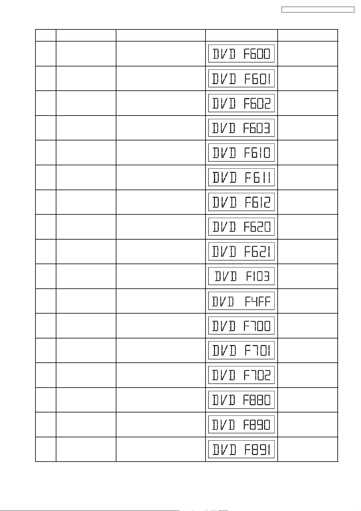
Error
Diagnosis Contents Description of error Automatic FL Display Remarks
Code
F600 Access failure to
management information
caused by demodulation
Operation stopped because navigation
data is not accessible caused by the
demodulation defect
Press [ n STOP] on main
unit for next error
error
F601 Indeterminate sector ID
requested
F602 Access failure to LEAD-IN
caused by demodulation
Operation stopped caused by the
request to access abnormal ID data
Press [ n STOP] on main
unit for next error
LEAD IN data unreadable Press [ n STOP] on main
unit for next error
error
F603 Access failure to KEYDET
caused by demodulation
Access failure to CSS data of disc Press [ n STOP] on main
unit for next error
error
F610 ODC abnormality No permission for command execution Press [ n STOP] on main
unit for next error
F611 No CRC OK for a specific
time (CD)
F612 No CRC OK for a specific
time (DVD)
Access failure to seek address in CD
series
Press [ n STOP] on main
unit for next error
Access failure to ID data in DVD series Press [ n STOP] on main
unit for next error
F620 Laser safeguard: high
temperature condition
F621 Laser safeguard: circuit
failure condition
F103 Illegal highlight Position Big possibility of disc specification
F4FF Force initialize failure (time
out)
High temperature of the laser guide unit
(OPU unit)
Circuitry failure of the laser guide unit
(OPU unit)
Press [ n STOP] on main
unit for next error
Press [ n STOP] on main
unit for next error
Press [ n STOP] on main
violation during highlight display
unit for next error
Timeout when force initialization fails Press [ n STOP] on main
unit for next error
F700 MBX overflow When replying message to disc manager Press [ n STOP] on main
unit for next error
F701 Message command does
not end
F702 Message command
changes
F880 Task number is not
appropriate
Next message is sent before replying to
disc manager
Message is changed before it is sent as
a reply to disc manager
Message coming from a non-existing
task
Press [ n STOP] on main
unit for next error
Press [ n STOP] on main
unit for next error
Press [ n STOP] on main
unit for next error
F890 Sending message when
message is being sent to
AV task
F891 Message couldn’t be sent
to AV task
Sending message to AV task Press [ n STOP] on main
unit for next error
Begin sending message to AV task Press [ n STOP] on main
unit for next error
25
SA-HT340E / SA-HT340EB / SA-HT340EG
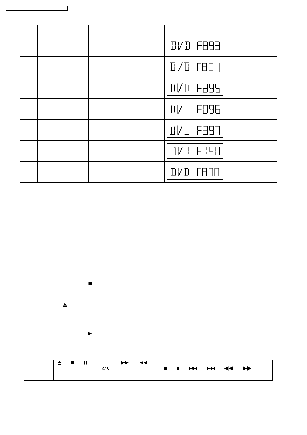
Error
Code
F893 FLASH ROM IC problem FLASH ROM IC installed is not operating
F894 EEPROM abnormality EEPROM IC installed is not operating in
F895 Region setting abnormality Firm version agreement check for factory
F896 No existence model Firm version agreement check for factory
F897 Initialize is not completed Initialize completion check for factory
F898 Disagreement of hardware
F8A0 Message command is not
Diagnosis Contents Description of error Automatic FL Display Remarks
properly (Neccessary replacement of
FLASH ROM IC) or firmware problem
normal condition (EEPROM contains
neccessary data)
preset setting failure prevention. Check
region setting & re-initialize
preset setting failure prevention
preset setting failure prevention
and software
appropriate
Unsuitable combination of AV
DECORDER, SDRAM and FLASH ROM
(firmware)
Begin sending message to AV task Press [ n STOP] on main
Press [ n STOP] on main
unit for next error
Press [ n STOP] on main
unit for next error
Press [ n STOP] on main
unit for next error
Press [ n STOP] on main
unit for next error
Press [ n STOP] on main
unit for next error
Press [ n STOP] on main
unit for next error
unit for next error
Note:
An error code will be canceled if a power supply is turned OFF.
*1: CPPM is the copy guard function beforehand written in the disk for protection of copyrights.
*2: CEC is the consumer electronic control used for high-level user control of HDMI-connected devices.
*3: HDCP is the specification developed to control digital audio & video contents transmission for DVI or HDMI connections.
8.4. Sales Demonstration Lock Function
This function prevents discs from being lost when the unit is used for sales demon strations by disabling the disc eject function.
"LOCKED" is displayed on the unit, and ordinary operation is disabled.
8.4.1. Setting
· Prohibiting removal of disc
1. Select the DVD/CD function.
2. Press and hold down the
“___LOCKED_” appears when the function is activated.)
Note:
OPEN/CLOSE
, DISC CHECK and DISC CHANGE buttons are invalid and the player displays “___LOCKED_” while
the lock function mode is entered.
· Prohibiting operation of selector and disk
1. Select the DVD/CD function.
2. Press and hold down the
“___LOCKED_” appears when the function is activated.)
Note:
The following buttons are invalid and the player displays “___LOCKED_” while the lock function mode is entered.
Player , , , SELECTOR, , , VOLUME KNOB, DISC CHECK, DISC CHANGE, DISC1-DISC5
Remote
controller unit
SLEEP, REPEAT, 0~9, , RETURN, TOP MENU, , , , , , ,
POSITION MEMORY, TUNER/BAND, D.MIX, CH SELECT/ TEST, SET UP/ MUTING, DISPLAY, GROUP, TV, VCR/
AUX, QUICK REPLAY, SUBTITLE, FL DISPLAY, CH & VOLUME
button and the power button on the player for at least three seconds. (The message,
button and the power button on the player for at least three seconds. (The message,
8.4.2. Cancellation
The lock can be cancelled by the same procedure as used in setting. ("UNLOCK" is display ed on cancellation. Disconnecting the
26

SA-HT340E / SA-HT340EB / SA-HT340EG
power cable from power outlet does not cancel the lock.)
8.5. Service Precautions
8.5.1. Recovery after the DVD player is repaired
· W hen the IC or HDMI module P.C.B. is replaced, carry out the recovery processing to optimize the drive.
Playback the recovery disk to process the recovery automatically.
· Recovery disc (Product number: RFKZD03R005)
· Performing recovery process
1. Load the recovery disc RFKZD03R005 [SPC] on to the player and run it.
2. Recovery is performed automatically. When it is finished, a message appears on the screen.
3. Remove the recovery disc.
4. Turn off the power.
5. Initialize the player.
8.5.2. Firmware version-up of the DVD player
· The firmware of the DVD player may be renewed to improve the quality including operability and playab ility to the substandard
discs.processing to optimize the drive.
The recovery disc has also firmware version-up.
· After version-up, recovery processing is executed automatically.
· Part number of the recovery disc for version-up will be noticed when it is supplie d.
· Updating firmware
1. Load the recovery disc on to the player and run it.
2. Firmware version of the player is automatically checked. Appropriate message appears whenever necessary.
3. Using remote controller´s cursor key, select whether version updating is to be done or not. (Selection of Yes/No)
4. a. If Yes is selected, version updating is performed.
b. If No is selected, only recovery is performed.
5. a. When updating is finished, remove the disc according to the message appearing on the screen.
b. Remove the disc according to the message appearing on the screen.
6. Turn off the power.
Note:
If the AC power supply is shut out during version-up due to a power failure, the version-up is improperly carried out.
In such a case, replace the FLASH ROM IC and carry out the version-up again.
8.5.3. DVD Module Reset
· W hen after replacing Flash Rom IC or the DVD Module P.C.B., FL display s error code “ DVD F897”. This means the unit is not
initialized properly and the following process needs to be carry out.
· Procedures:
1. Press
2. FL display show “INIT” on main unit.
3. While still pressing “STOP” button on main unit, press “ENTER” on remote control. (In initialization mode)
4. FL will display “RESET” before FL display will change to TOC reading again.
5. Power off unit. Unplug the AC cord.
6. Power on the unit. It should be no problem. If problem persist check on the DVD module P.C.B. or FLASH ROM IC.
on remote control while pressing “STOP” button on main unit. (To enter into initialization mode)
27
SA-HT340E / SA-HT340EB / SA-HT340EG
9 Assembling and Disassembling
“ATTENTION SERVICER”
Be carefu l when disassembling and servicing.
Some chassis components may have sharp edges.
Special Note:
1. This section describes the disassembly procedures for all the major printed circuit boards and main components.
2. Before the disassembly process was carried out, do take special note that all safety precautions are to be carried out.
(Ensure that no AC power supply is connected during disassembling.)
3. For assembly after operation checks or replacement, reverse the respective procedures.
Special reassembly procedures are described only when required.
4. The Switch Regulator IC may have high temperature after prolonged use.
Use caution when removing the top cabinet and avoid touching heat sinks located in the unit.
5. Select items from the following index when checks or replacement are required.
· Disassembly of Top Cabinet
· Disassembly of DVD Lid (When taking out disc manually)
· Disassembly of Front Panel
· Disassembly of FL P.C.B. & Volume P.C.B.
· Disassembly of Mechanism Unit
· Disassembly of DVD Module P.C.B.
· Disassembly of Rear panel
· Disassembly of SMPS Module P.C.B.
· Disassembly of Main P.C.B. & Tuner Extent P.C.B.
· Disassembly of Digital Amp IC
lSMPS Module P.C.B. (SMPS) Replacement
1. This model uses SMPS Module to provide the necessary supply voltages for the unit.
2. It is advisa ble to replace the SMPS Module once upon detecting of non-working conditions. Do not attempt to repair
or replace it by components.
3. Non-working conditions include:
lWith AC supply but no supply voltages after checking at CN2 and/or CN3 respec tively.
lBroken fuse. (Substitute compatible part for fuse: K5D312BNA005)
lWire connection problem.
lNon-working parts in SMPS Module P.C.B. (Check components)
28
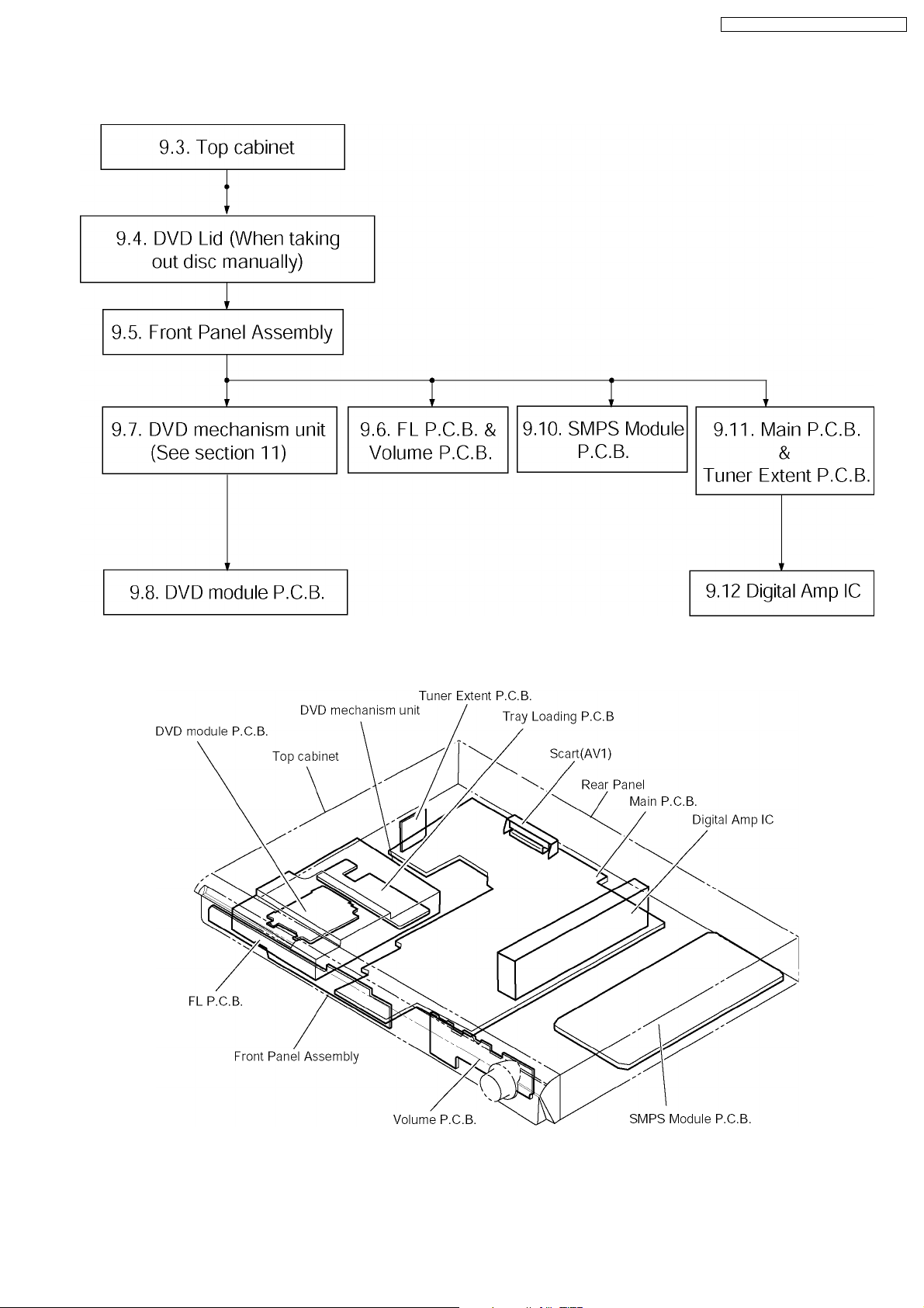
9.1. Disassembly Flow Chart
SA-HT340E / SA-HT340EB / SA-HT340EG
9.2. Main Components and P.C.B. Locations
29
 Loading...