

Panasonic RFD-5-EB, RFD-7-EB, RFU-300-EG, RFU-350-EG Service manual
ORDER NO. MD0706008SE
FM Radio/DAB-FM Radio
RF-U300EG
RF-U350EG
RF-D5EB
RF-D7EB
Colour
(K) .... Black Type (For RF-U300EG & RF-D5EB only)
(S) .... Silver Type (For RF-U350EG & RF-D7EB only)
Subject :
Please use this supplement manual together with the service manual for Model No. [RF-U300EG-K, Order
No. MD0704062CE], [RF-U350EG-S, Order No. MD0704063CE] , [RF-D5EB-K, Order No. MD0704060CE] and
[RF-D7EB-S, Order No. MD0704061CE].
Measurement and Adjustment (Additional)
CONTENTS
Page Page
1 Measurement and Adjustment 2
1.1. Instrument and Jig to be used
1.2. Preparation for alignment
2
2
1.3. FM alignment 2
1.4. AM alignment
3
© 2007 Matsushita Electric Industrial Co., Ltd. All
rights reserved. Unauthorized copying and
distribution is a violation of law.
U300EG / RF-U350EG / RF-D5EB / RF-D7EB
1 Measurement and Adjustment
1.1. Instrument and Jig to be used
• Signal generator
• Oscilloscope and electronic voltmeter
• Headphone jig
• FM dummy antenna
1.2. Preparation for alignment
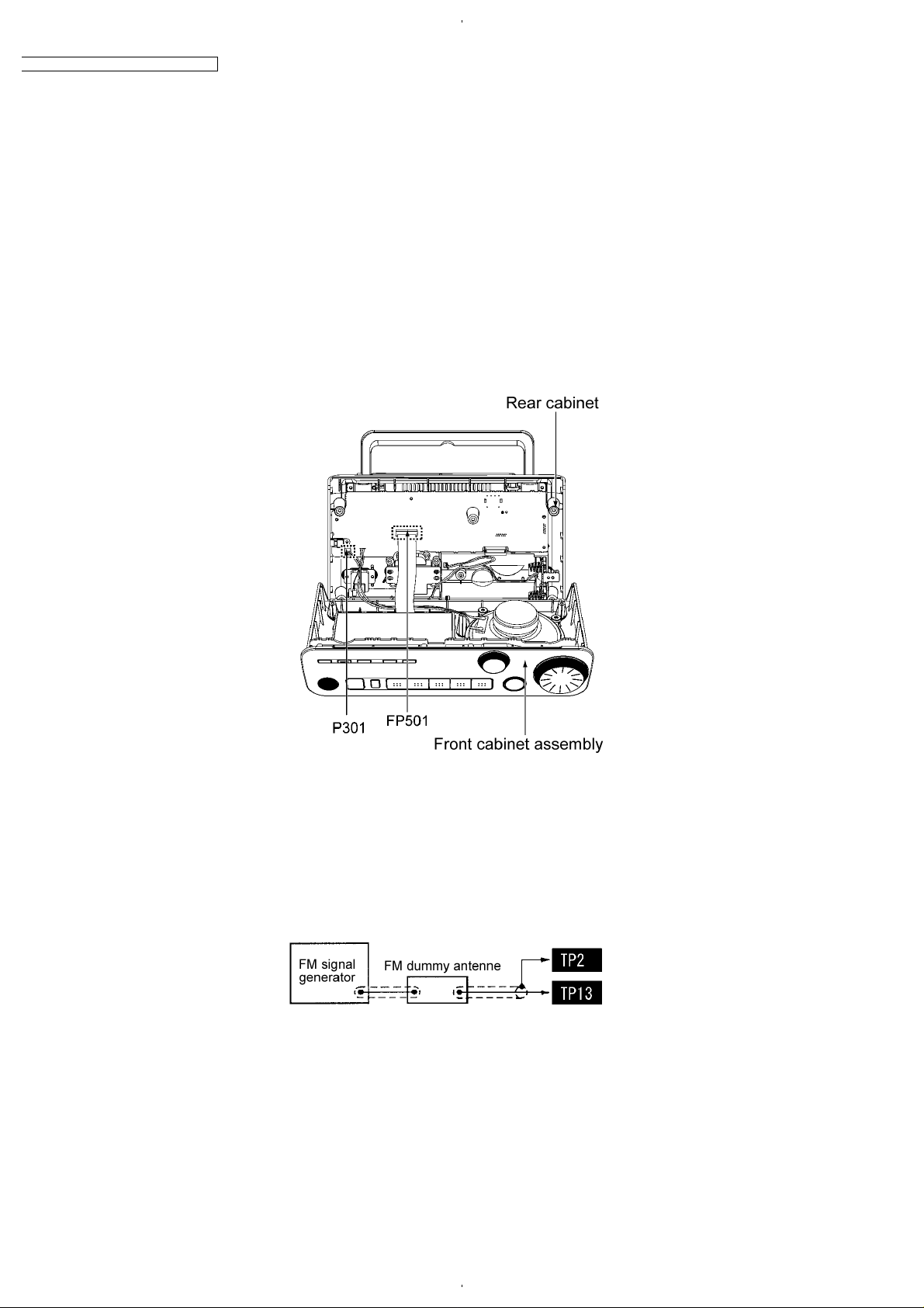
• Referring to “Disassembly for Front Cabinet Assembly” of “Disassembly and Main Component Replacement Procedures and
Operational Check”, set up the unit.(Fig.1-1)
• Connect the unit to power source (AC 230-240V).
• Set the volume of the unit to Max.
• As for the test points, refer to Print Circuit Board and Schematic Diagram.
Fig.1-1
1.3. FM alignment
1.3.1. FM RF alignment
1. Set the frequency of FM signal generator to 98.0MHz.
2. Input to TP13-TP2 of IC1 through the FM dummy antenna. (see Fig.1-2)
3. Adjust T3 so that the output will be maximized. (see Fig.1-4)
Fig.1-2
1.3.2. FM IF alignment
1. Set the frequency of FM signal generator to 5ch (98.0MHz).
2. Input to pin 5 of IC1 through the FM dummy antenna.
3. Rotate the core of T3 so that the output wave will be the largest (see Fig.1-4)
2
 Loading...