

Panasonic CZ-RWST2U installation
Installation Instructions
Wireless Remote Controller
Model No.
CZ-RWST2U
1-1.
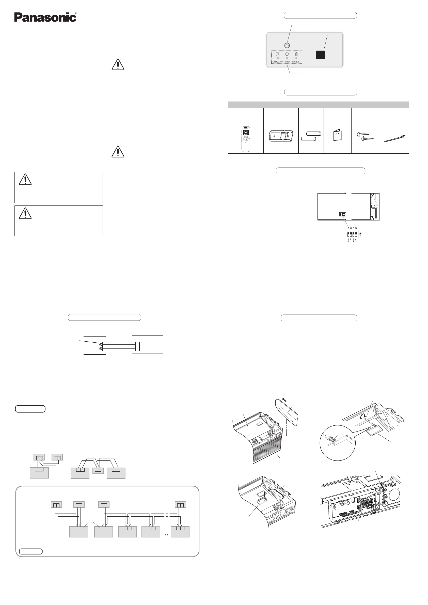
Part Names
(2) Emergency operation button
Starts/Stops emergency operation.
(1) Light receiving section
Receives signals.
Safety Precautions
Read before installation
Read the Installation Instructions carefully
to install the remote controller correctly and
safely.
Be sure to read the Safety Precautions in
particular before installation.
After the installation is complete, perform
test operation to conrm that no abnormality
is present.
We assume no responsibility for accidents
or damages resulting from methods other
than those described in the installation
instructions or methods without using
specied parts.
Malfunctions that occurred due to the
unauthorised installation methods are not
covered by the product warranty.
Read the installation instructions supplied
with indoor units as well.
WARNING
This symbol refers to a hazard or unsafe
practice which can result in severe personal
injury or death.
CAUTION
This symbol refers to a hazard or unsafe
practice which can result in personal injury or
product or property damage.
WARNING
• Turn o the circuit breaker of the units
before installation.
• Ask your dealer or professionals for
installation and electric work.
• This controller shall be installed in
accordance with National Wiring
Regulations.
• Connect and x the specied cables for
wiring securely.
• Do not allow the connection to be exposed
to the external force of the cables.
• Choose an installation location that
suciently supports the weight of the
remote controller.
CAUTION
Do not use the remote controller at the
following locations.
• Location where condensation occurs
• Location where ammable gases, etc. may
leak
• Location where corrosive gases, etc. may
leak
• Location with lots of water or oil droplets
(including machine oil)
• Location where voltage uctuation
frequently occurs
• Location where there is a machine
producing electromagnetic radiation
• Location where droplets of organic
solvents spread
• Location where acidic or alkaline solutions
or special sprays are frequently used
Do not operate with wet hands.
Do not wash with water.
(3) Indication lamp
1-2. Supplied accessories
Supplied accessories
Wireless Remote
Controller
(1)
Remote Control
Holder
(1)
AAA Size
Battery
(2)
1-3. Settings
Before installing the receiver, see the
sections on “Wiring for the Receiver” and
“Setting Address Switches”. Then check
the settings of the [S003] DIP switch on the
receiver’s PCB.
* Remove the cover from the receiver when
performing the PCB settings.
Indicates operation status.
Operating
Wood Screw
Instructions
(1)
Set its
address
(1) to (3)
Clamper
(2)
All set at OFF
when shipped
from the factory.
ON
Main/Sub selector
switch for remote
controllers (4)
OFF: Main ON: Sub
(1)
Printed in Japan
85464369841010
- 1 -
DC0815-0
CV 6233317724
1-4. Wiring for the Receiver
Wiring Diagram
Receiver PCB
CN001
2P white
Terminals for RC
wiring
Indoor unit
1
2
How to Connect the Wires
Connect the wires from the receiver to the terminals for RC wiring on the indoor unit.
(No polarity)
Installation Location for the Reciver
The wireless remote controllers use a very weak infrared light for its signal, which can result in the signal
not being received because of the following inuences, so take care in where the unit is installed.
• Inverter or rapid-start type uorescent lights (Models without glow lamps)
• Plasma display or LCD televisions
• Direct sunlight or other sources of bright light
Attention
Multiple wireless remote controllers cannot be used simultaneously for a single indoor unit.
Be careful not to connect cables to other terminals of indoor units (e.g. power source wiring terminal).
Malfunction may occur.
Do not bundle together with the power source wiring or store in the same metal tube. Operation error may
occur.
If noise is induced to the unit power supply, attach a noise lter.
*Wiring shown below is prohibited.
Wired RC Receiver
1 2 1 2
RC wiring
R1 R2
Indoor unit Indoor unit Indoor unit
Installation when setting Main/Sub for the remote controller and the receiver
Using 1 indoor unit
Installation
example
After installation, according to the “Settings” section, set one to [Main] and the other to [Sub].
Setting the wired remote controller to [Main] is recommended.
Note
Receiver (Sub) Receiver (Sub)
RC wiring
(eld supply)
• No polarity
The remote controller and the receiver can be connected to any indoor unit for operation.
R1 R2 R1 R2
Wired RC (Main)
1 21 2
R1 R2
Indoor unit
1 2
Receiver
Using more than 1 indoor unit
1 2 1 2
Terminals for
RC wiring
Indoor unit Indoor unit Indoor unit Indoor unit
RC wiring (eld supply)
• No polarity
Wired RC (Main)
R1 R2R1 R2R1 R2R1 R2
- 2 -
1-5. Installing the Receiver
1 Open the air inlet grill on the side panel. Remove the 1 screw and move it toward the front
(in the direction of an arrow) to remove it. (Fig. A)
2 Wrap the tip of a slotted screwdriver with plastic tape and then insert it under the O-marked
surface of the cover, wiggling the cover free. (Fig. B) (Be careful not to scratch the panel.)
3 After passing the lead wire through the panel, install the receiver in the hole in the panel.
(The projecting parts of the receiver is held in the hole in the panel.)
4 Fasten the receiver’s lead wire to the cable clip that is holding the wire from the louver motor.
(Fig. C)
5 Attach the side panel.
6 Put the receiver’s lead wire together with other wires such as the louver motor wire, and fasten
them with the cable clip. (Fig. D)
Use the hole in the upper part of the wiring box to lead it in.
For more information about wiring and test runs, see the sections on “Wiring for the Receiver” and
“Test Operation”.
Fig. A Fig. B
Side panel
Panel
Plastic tape
Insert it under the
O-marked surface
of the cover.
Air inlet grill
Fig. C Fig. D
Cable clip
Receiver
Slotted screwdriver
(Wrapped with plastic tape)
Cover
Cable clip
Panel
- 3 -
- 4 -
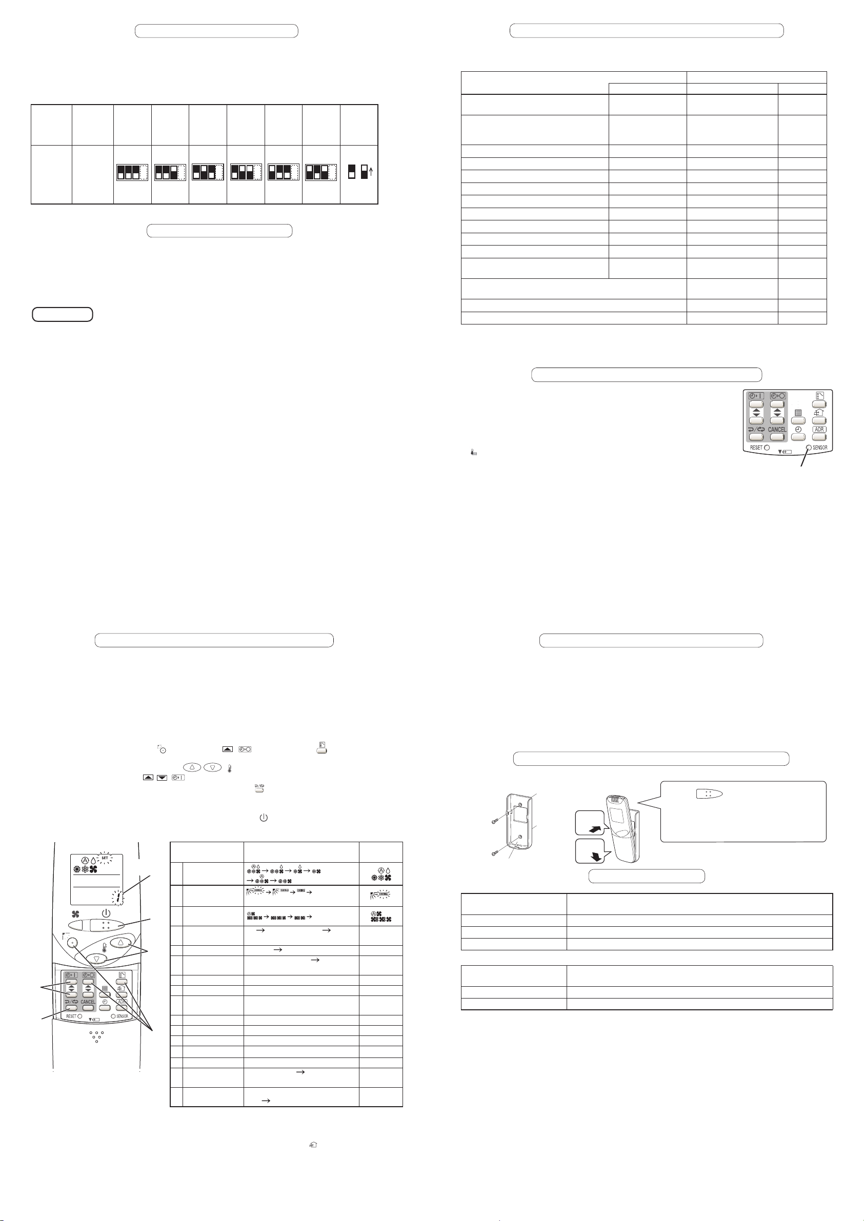
1-6. Setting Address Switches
When more than 1 receiver is installed in the same room, setting addresses prevents
interference.
For how to change addresses of wireless remote controllers, see the operating instructions of
wireless remote controllers.
To change the receiver’s address, remove the cover from the receiver’s PCB and set No.1 to
No.3 of the [003] DIP switch on PCB.
Remote
Controller
Address
Display
Position
of the
receiver’s
address
switch
Address Address Address Address Address Address Address
ALL 1 2 3 4 5 6
Receipt is
possible
at all
of the
address
positions
1234
1234
1234
1234
1234
1234
ON/OFF
States
OFF ON
1-7. Test Operation
Preparation:
1. To start test operation, press and hold the emergency operation button for 10 seconds.
2. The indication lamps (OPERATION, TIMER, STANDBY) blink during test operation.
3. To nish test operation, press and hold the emergency operation button for 10 seconds.
Attention
Do not use this mode for purposes other than
the test operation.
(To prevent overload of the units)
Read the installation instructions supplied with the units.
Any of the Heat, Cool and Fan operations can
only be performed.
Turn on the circuit breaker of units and then turn the power on. After the power is turned
on, remote controller operation is ignored for approx. 1 minute because setting is being
made. This is not malfunction. (Contents received while setting are disabled.)
Temperature cannot be changed.
The test operation mode is automatically
turned o in 60 minutes.
(To prevent continuous test operation)
Outdoor units do not operate for approx. 3
minutes after the power is turned on or
operation is stopped.
1-8.
Self-diagnostics table and detected contents
The “Alarm Display” shown in the table below expresses the alarm contents displayed when the
wired remote controller is connected. For how to handle the alarms, see installation instructions
of indoor units or technical guide.
Detected contents Indication lamp on the receiver
Alarm Display
Communication error in the remote
controller circuit
Communication error either in the in/
outdoor operation line or the sub-bus of
the outdoor unit
Operation of indoor protection device
Operation of outdoor protection device P02–P08, P15–P31
Error in the indoor thermistor F01–F03, F10–F11
Error in the outdoor thermistor F04–F09, F12–F28
Error in the indoor EEPROM F29
Error in the outdoor EEPROM F30, F31
Error related to the compressor H01–H31
Error in indoor settings L01–L03, L05–L09
Error in outdoor settings L04, L10–L31
Error in the gas heat pump air
conditioner
Inconsistency in Cooling/Heating (Including an auto-temp
setting for a model without auto-temp settings)
Oil alarm (Same as operation of outdoor protection device)
Test operation
: OFF : ON (Illuminated) ◎: Blinking (0.5 seconds interval)
1-9.
Room Temperature Sensor Settings
The indoor unit and the wireless remote controller are equipped with
E01–E03, E08–E14,
E17, E18
E04–E07, E15, E16,
E19–E31
P01, P09–P14
A01-A31
OPERATION TIMER STANDBY
◎
◎
◎ ◎
◎ ◎
◎ ◎
◎ ◎
◎
◎
◎
◎ ◎ ◎
◎
◎ ◎
◎
◎
◎
◎
◎ ◎
◎ ◎
◎
Blinking
Alternately
Alternately
Alternately
Alternately
Simultaneously
Simultaneously
Simultaneously
Simultaneously
Simultaneously
Alternately
Alternately
Simultaneously
room temperature sensors. The sensing of room temperature works
via one of them.
When the unit is shipped, it is set to the indoor unit. To switch it to the
remote controller, press the sensor button (the gure on the right)
inside the remote controller’s cover and then check that Main Sensor
on the LCD screen goes o.
<Note> Be sure to install the remote controller so as to face the
receiver.
Sensor button
If the unit does not receive any room temperature data from
the remote controller for ten minutes even with its sensing
function activated, the indoor unit sensor will automatically
start sensing the room temperature.
- 5 -
1-10.
Setting Up Remote Controller Functions
The functions of the wireless remote controller can be set on site.
(These settings are saved in nonvolatile memory in the remote controller. Therefore, the settings
do not revert to the defaults even when its batteries are changed.)
<Note> Only service personnel should make the settings because the operation of the air
conditioner may be aected, depending on the settings made.
Furthermore, making changes to these settings may cause actual operation to deviate
from what is printed in the Operating Instructions, so be sure to fully explain this to the
customer.
Making Settings (Do with unit stopped)
(1) Holding down the swing/ap ( ) + OFF timer ( ) + mode select ( ) buttons at the
same time for 4 or more seconds will open the setting screen. (See gure below.)
(2) Use the Temperature setting buttons
(3) Use the ON timer buttons
/ ( ) to change settings.
/ (
(4) The settings are saved with the once/every day button (
) to select the number of the item to be set.
). When this is done, the SET
displayed on the LCD changes from blinking to lighting.
(5) If other settings are to be changed, repeat steps (2) to (4).
(6) When all settings have been made, press the start/stop (
) button.
Operation procedure and function display
Factory
setting
AM/PM
86°F (30°C)
64°F (18°C)
86°F (30°C)
(*4)
60°F (16°C)
86°F (30°C)
64°F (18°C)
80°F (27°C)
62°F (17°C)
JP
(3)
(4)
Item
Number
(6)
(2)
(1)
Detected contents Set Contents
1 Operation
Mode
2 Flap Display
3 Select Fan
Speed
4 Display of Set
Temperature
5 Time Display
6 Ventilation Fan
ON/OFF
7 Cool temp Max 41 to 95°F (05 to 35°C)
8 Cool temp Min 41 to 95°F (05 to 35°C)
9 Heat temp Max 41 to 95°F (05 to 35°C)
10 Heat temp Min 41 to 95°F (05 to 35°C)
11 Dry temp Max 41 to 95°F (05 to 35°C)
12 Dry temp Min 41 to 95°F (05 to 35°C)
13 Auto temp Max 41 to 95°F (05 to 35°C)
14 Auto temp Min 41 to 95°F (05 to 35°C)
16 Address Setting
Max Value
17 Heat temp Max
ON/OFF
(No Display)
(*1)
°F Setting O (*2) °C °F
AM/PM 24 Hour (No Display)
OFF (No Display)
00 (ALL only) 01 to 031 06(*5)
JP (Heater Max Temp Change
O)
EP (ON)
(No Display)
ON OFF (*3)
<Note 1> While the unit is in the SWING mode (swing/ap), the ap cannot be stopped in a
desired position.
<Note 2> When Setting OFF is selected, “°C” is displayed on the LCD.
<Note 3> You can toggle between ON and OFF by pressing ventilation “(
) button” for 4 seconds
or more.
<Note 4> If the Heater Max ON/OFF setting is not changed to EP (ON), the setting change will
not be reected.
<Note 5> This is the number of addresses that can be set in the address change mode. Do not
set it to 07 or above.
- 7 -
- 6 -
1-11.
Installing Wireless Remote Controller
Installation location for the Wireless Remote Controller
If a remote controller is to be operated from a remote control holder that is hung on a wall, turn on the lights in
the room as well as any electrical appliances and then check to make sure the air conditioner works with the
remote controller in the location where it will be installed. If it works, continue with installation.
If the main sensor is to be switched from the indoor unit to a remote controller, pay attention to the following
when installing.
•
Locate where no warm or cold air will aect it.
•
Locate in a place free from direct sunlight.
•
Locate where it will not be aected by any other heat/cold source.
1-12.
When installing the remote controller onto a wall, etc.
Screw the remote control
holder.
Remote control holder
Wireless Remote Controller
Dimensions
Weight 140g (Including batteries)
Power Source Two AAA size batteries
Clock Accuracy ±30 seconds / month (at 77°F (25°C))
Receiver
Dimensions
Weight 85g
Power Source DC16V(supplied from indoor unit)
Installing the remote
controller
2
Press
1
Insert
1-13.
Specications
(H) 7-11/64” × (W) 2-13/32” × (D) 47/64”
((H)182 mm × (W) 61 mm × (D)18.5 mm)
(H) 2-9/16” × (W) 5-35/64” × (D) 57/64”
((H) 65 mm × (W)141 mm × (D) 22.5 mm)
Press
on the wall, and check that normal
receiving is possible.
Remove the remote controller from the
remote control holder.
- 8 -
at the installation location
 Loading...