

Page 1
OPERATION MANUAL
ENGLISH
PACKAGED AIR CONDITIONER
CENTRAL REMOTE CONTROLLER
Model No.
CZ-01ESM11P
En.
Thank you for purchasing Panasonic’s central remote controller.
For proper usage, read this instruction manual carefully before using this unit.
This manual will help you with anything you can not understand or should anything go wrong with the unit during
use.
Keep this manual handy for future reference.
NOTES:
This unit is connected to multiple air conditioners. Keep the installation list showing the configurations together
with this manual.
Ge.
Wir danken Ihnen für den Kauf der zentralen Fernbedienung von Panasonic.
Lesen Sie bitte diese Anleitung bevor Sie das Gerät in Betrieb setzen durch, um es richtig zu verwenden.
Diese Anleitung wird Ihnen Ungewißheiten aufzuklären oder evtl. auftretende Betriebsstörungen zu korrigieren
helfen.
Bewahren Sie diese Anleitung für spätere Bezungnahme griffbereit auf.
HINWEISE:
Dieses Gerät ist an mehrfache Klimageräte angeschlossen. Bewahren Sie die Installationsliste, aus der die
Konfiguration ersichtlich ist, zusammen mit dieser Anleitung auf.
DEUTSCH
FRANÇAIS
ESPAÑOL
ITALIANO
NEDERLANDS
Before operating this set, please read these instructions completely
Page 2
FEATURES AND FUNCTIONS
■ Operation menu
This central remote controller enables the individual operation/stop
by zone, and unified operation/stop. ON/OFF operation controlled by
timer is possible in conjunction with the schedule timer (optional
accessory).
■ Various operation modes.
You can operate the system from both this unit and the remote
controller, so to enable various operation control patterns. Twenty
different operation modes are available including five operation
patterns: ON/OFF control impossible by remote controller, only OFF
control possible by remote controller, centralized, individual and
centralized (ON/OFF control possible by remote controller only with
the timer ON); and temperature setting possible/impossible by
remote controller and operation mode selecting possible /impossible
by remote controller.
■ Zone control for simpler operation
You can control a maximum of 64 groups of indoor units by using
this central remote controller. You don’t have to repeat the same
setting operations by group because you can make each of the
following settings by zone.
䡬 Operation mode
䡬 Control mode
䡬 Setting temperature
䡬 Programming time No. (Used in conjunction with the
schedule timer)
See page
22—23, 31.
See page 24.
See page
22–28.
ENGLISH
■ Monitor and display operating conditions of
indoor units by group
You can display operating conditions such as operation mode and
preset temperature; maintenance information such as time to clean,
etc.; and information on trouble such as malfunction codes.
❈ “Time to clean” sign refers to the following functions.
䡬 Display the time to clean air filter and the air cleaner element
of electric dust collector for each group.
䡬 Display the time to clean when signaled from any given
group.
See page
28–30.
■ Function of refrigerant system display
This display helps you understand, at a glance, the indoor units
sharing the same outdoor unit and the particular indoor unit among
them that is set as the master remote controller.
● Utilizing one of the PC board adaptors (optional accessories) will enable you to combine this unit with the split
A/C units and unitary A/C.
However, be sure to refer to the installation manual attached to each PC board adaptor for function limitations.
See page 30.
18
Page 3
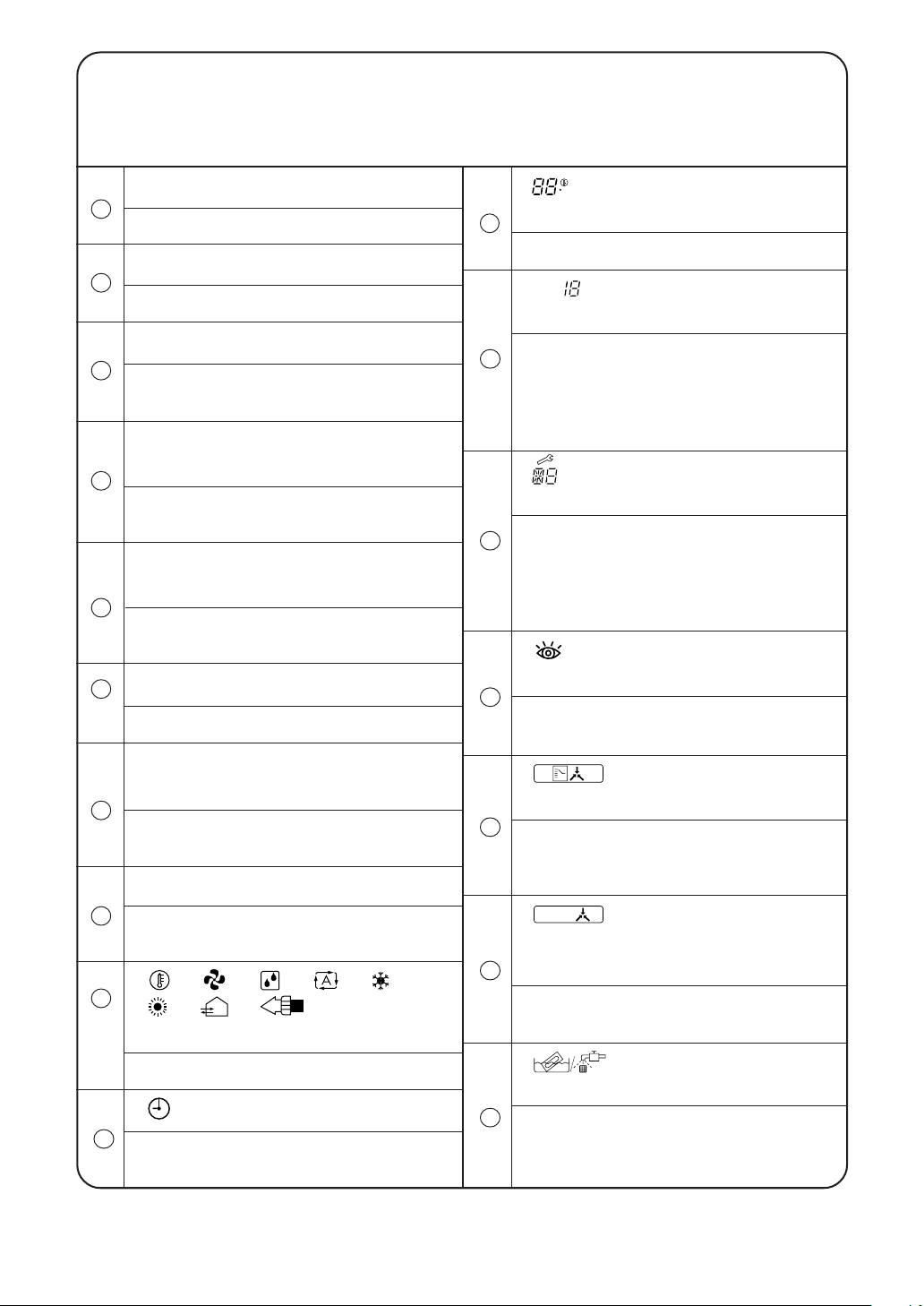
NAMES AND FUNCTIONS OF THE
OPERATING SECTION (Fig. 1, 2)
UNIFIED OPERATION BUTTON
1
Press to operate all indoor units.
UNIFIED STOP BUTTON
2
Press to stop all indoor units.
OPERATION LAMP (RED)
3
Lit while any of the indoor units under control
is in operation.
REF.
“ ” DISPLAY (REFRIGERANT
CIRCUIT
SYSTEM DISPLAY)
4
The indication in the square is lit while the
refrigerant system is being displayed.
“ MONITOR ” DISPLAY (OPERATION
MONITOR)
5
The lamp is lit while operation is being
monitored.
ZONE
SET
“ ” DISPLAY (ZONE SETTING)
6
The lamp is lit while setting zones.
“
” DISPLAY (PRESET TEM-
C
PERATURE)
11
Displays the preset temperature.
CODE
“
” DISPLAY (CONTROL
No.
MODE)
Displays codes on how to control equipment
12
(ON/OFF control impossible by remote
controller, centralized, individual etc.).
Displays the No. of the particular unit that has
stopped due to malfunction.
“ ” DISPLAY (MALFUNCTION
CODE)
Displays the contents of a malfunction. The
13
lamp flashes when a malfunction stops
operation. The contents of the current
malfunction are displayed in the inspection
mode.
TEST
“
” DISPLAY (INSPEC-
TION/TEST)
14
Press the inspection/test operation button.
Either the inspection or test lamp lights up.
19
“ZONE” “GROUP” DISPLAY
(ZONE/GROUP)
7
Indicates the particular zone or group being
displayed.
GROUP NO. IN OPERATION
8
Each square displays the state corresponding
to each group.
“ ” “ ” “ ” “ ” “ ”
9
“
” “ ” “ ” DISPLAY
(OPERATION MODE)
Displays operating state.
No.
“
10
Displays the operation timer No. when used in
conjunction with the schedule timer.
” DISPLAY (TIME NO.)
“ ” DISPLAY (CHANGE-
OVER UNDER CONTROL)
15
Cool/heat selection is not possible for either
the zone or the group where this particular
display appears.
HOST
“
” DISPLAY (UNDER
HOST COMPUTER INTEGRATED
CONTROL)
16
Setting is not possible while this display is
being displayed.
“ ” DISPLAY (TIME TO
CLEAN)
Displayed to notify the user it is time to clean
17
the air filter or air cleaner element of a
particular group.
Page 4
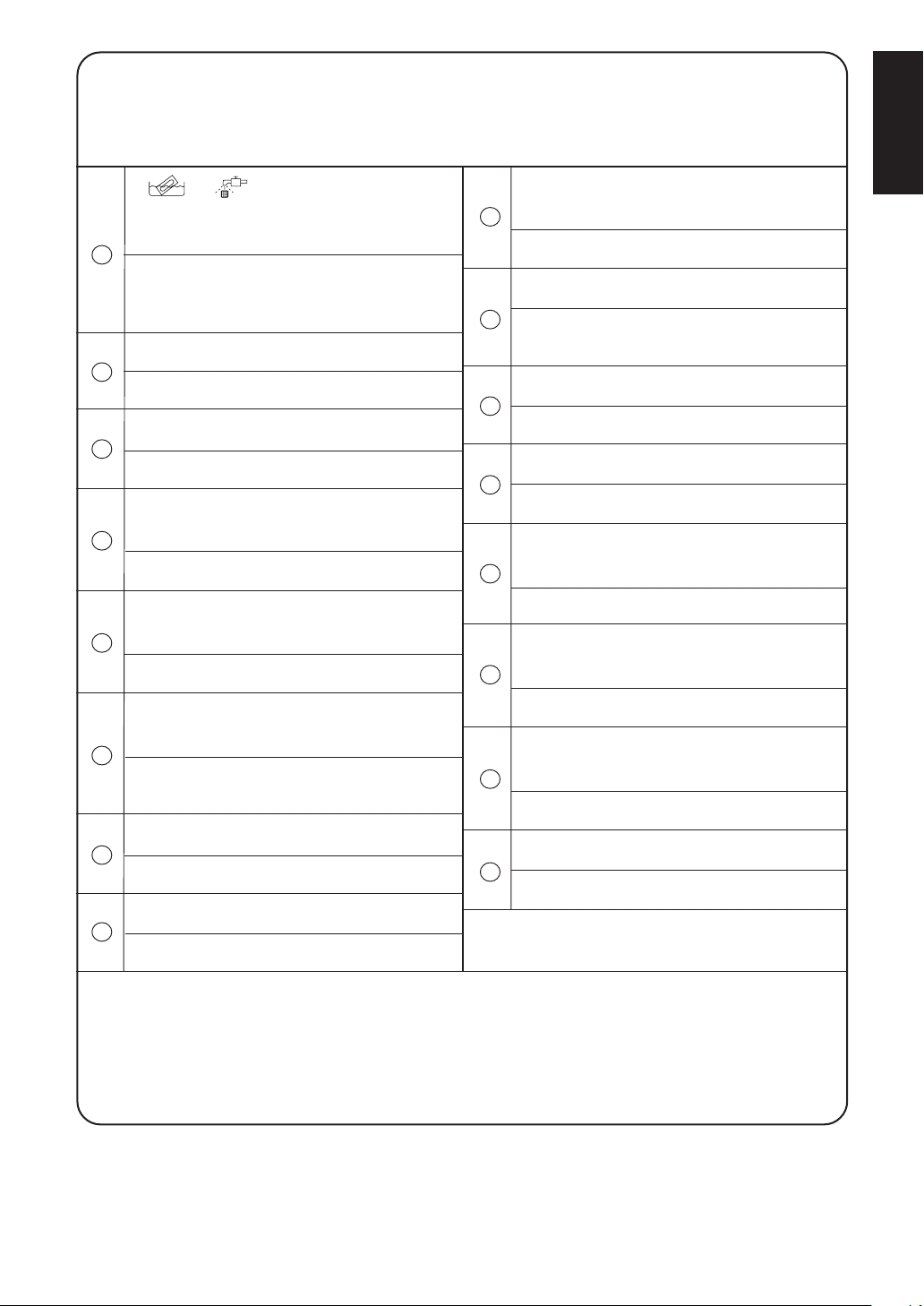
“ ” “ ” DISPLAY (TIME TO
CLEAN AIR CLEANER ELEMENT/
TIME TO CLEAN AIR FILTER)
18
Displayed to notify the user it is time to clean
the air filter or air cleaner element of the group
displayed.
ZONE SETTING BUTTON
19
Turns zone setting mode ON/OFF.
SELECTOR BUTTON
20
Selects the group to be assigned to a zone.
ZONE OPERATION ON/OFF BUTTON
21
Finalizes the zone.
BUTTON FOR REFRIGERANT
SYSTEM DISPLAY
22
See page 30.
TEMPERATURE SETTING BUTTON
26
Press to set temperature.
TIME NO. BUTTON
27
Selects time No. (Use in conjunction with the
schedule timer only).
CONTROL MODE BUTTON
28
Selects control mode.
TIMER ON BUTTON
29
Sets control mode and time No.
OPERATION MODE SELECTOR
BUTTON
30
See page 27.
INSPECTION/TEST OPERATION
BUTTON
31
ENGLISH
ZONE/GROUP CHANGEOVER
BUTTON
23
Switches display “zone” to display “group” or
vice versa.
Press to run inspection or test run.
CLEARING BUTTON FOR MALFUNCTION CODE MEMORY
32
Press to clear malfunction code.
ADVANCE/BACKWARD BUTTON
24
See page 21.
FILTER SIGN RESET BUTTON
33
See page 30.
ON/OFF BUTTON
25
Starts/stops operation by zone.
(Notes)
1. Please note that all the displays in the figure appear for explanation purposes or when the cover is open.
2. If the unit is used in conjunction with other optional central controllers, the OPERATION LAMP of the unit
that is not under operation control may light up and go out a few minutes behind schedule. This shows
that the signal is being exchanged, and does not indicate any failure.
20
Page 5
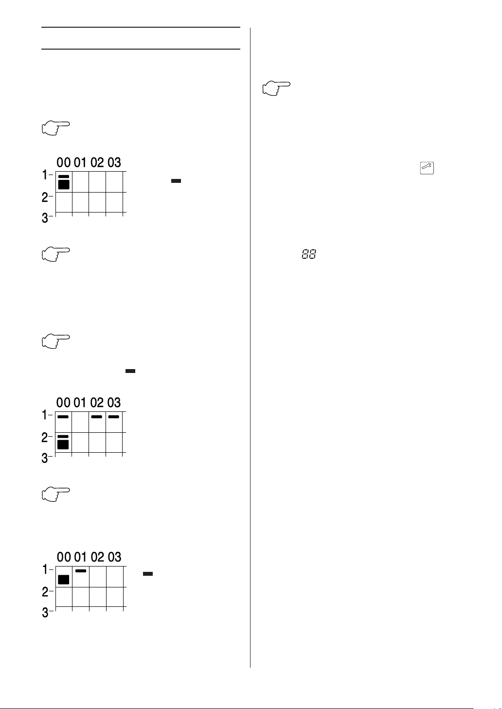
ZONE SETTING (Fig. 3)
You can set multiple groups under a single zone to
control them by zone. This equipment is factory set
for 64 zones of 1 group per every zone at the time of
shipment.
1
Press the ZONE SETTING BUT-
TON, and “ ” is displayed.
2
Press the ADVANCE/ BACKWARD BUTTON to move the display
“ ■ ” to the group of the desired
zone. Holding the button down will
quickly move the display.
3
Press the SELECTOR BUTTON
to set the above group in the zone.
The display “
group lights up.
4
Press the ZONE OPERATION
ON/OFF BUTTON to finalize the
zone. This zone becomes finalized,
and the next zone No. is displayed.
ZONE
SET
Zone No. 1 is displayed.
Then, operation monitor
display “ ” of group No.
lights up in the displayed
zone. The display “ ■ ” of
the lowest group No. lights
up.
” of the selected
Repeat procedures 2 – 3 to
select all desired groups for
the zone.
The example in the left,
groups 1-00, 1-02, 1-03 and
2-00 are set in the zone No.
1.
The zone No. advances
one at a time. The display
“ ” of the group that has
already been set is lit in the
displayed zone. The
display “ ■ ” of the lowest
group No. lights up again.
Set the other zones as well
following procedures 2 – 4.
In the above example, the zone No. 2 is displayed.
Then, the display “ ■ ” of the lowest group No. that
has already been set lights up.
5
Press the ZONE SETTING BUT-
TON again, to finish zoning.
The current display goes out, and the normal
display appears.
NOTES
● To clear all registered zones
Display “ ”. Then, hold down both “
ALL 䡬 for about 4 seconds. This will clear all
registered zones.
● If you have set a group in the wrong zone, reset it in
the correct zone. (The last zone set is judged to be
effective.)
● You cannot set the same group in multiple zones.
● When you turn ON the power, the system may
display “ ” for approximately one minute and
may not respond to operation until all the liquid
crystal display appears.
● Unless operated from within one minute from when
the display of zoning appears, the display will
automatically revert back to the “group” display.
● A single setting will simultaneously determine the
same setting of all the groups in the zone. So, pay
attention to the following points in setting the zone.
1. The control mode must be the same for all groups
in the zone.
2. The scheduled operation must be the same for all
groups in the zone, if the operation is controlled by
the timer.
3. The cool/heat operation mode must be the same
for all groups in the zone.
4. The preset temperature must be the same for all
groups in the zone.
Note) Be sure to select the “ – – ” in executing the
ZONE
SET
operation by zone, as well as to set the
operation mode and the temperature setting
unless the uniform operation is performed in
the above 3 and 4. (See page 22.)
RESET
” and
21
Page 6
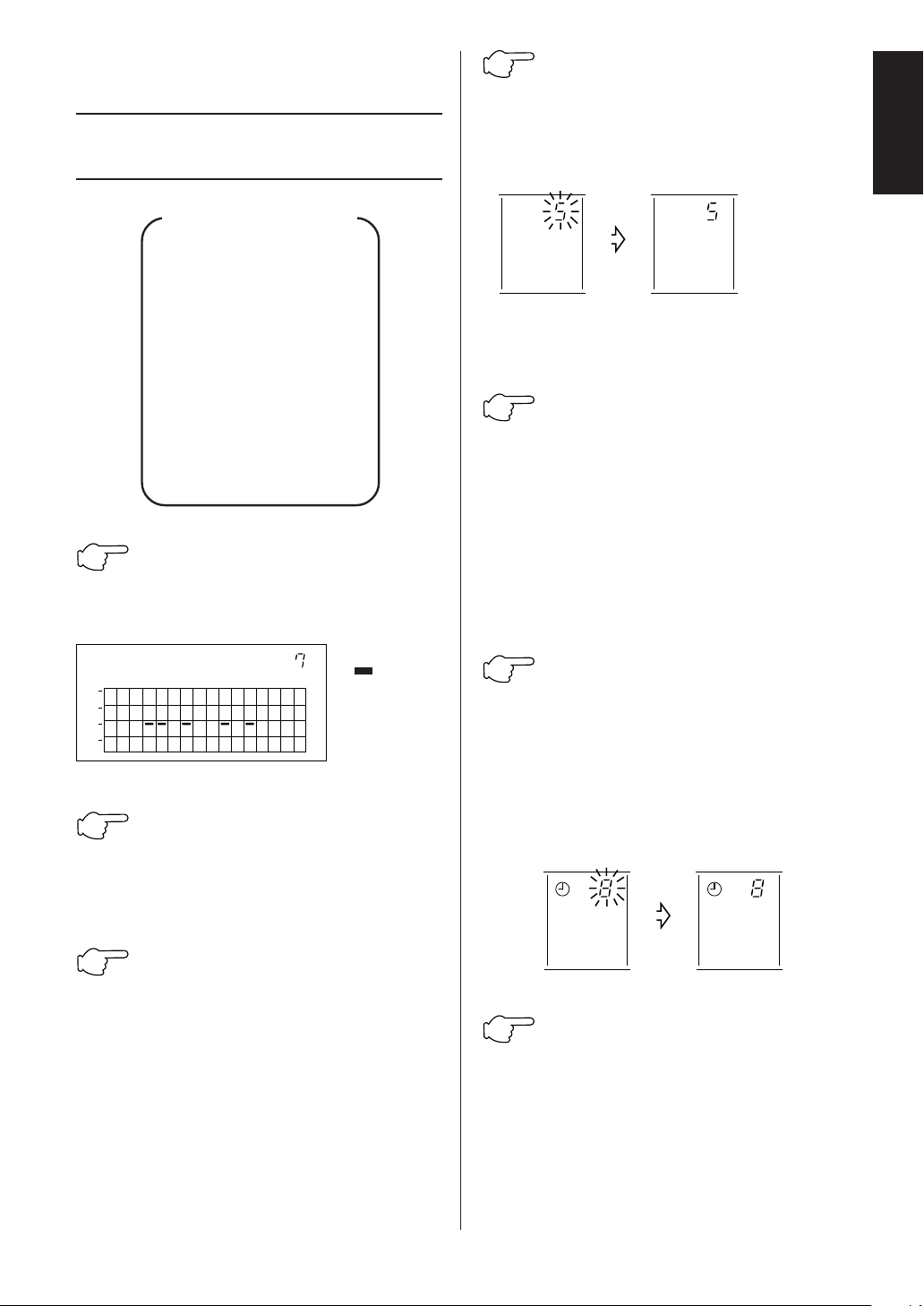
OPERATION
OPERATION BY ZONE
(Fig. 4)
4
Press the TIMER ON BUTTON.
Press the TIMER ON BUTTON within
10 seconds after the code No. is
displayed. The display stops flashing and lights up solidly.
ENGLISH
Flow of operation by zone
Call up the desired zone.
▼
Set the control mode.
▼
Set time No.
▼
Set operation mode.
▼
Set temperature.
▼
Start operation.
▼
Stop
1
Press the ZONE/GROUP
CHANGEOVER BUTTON, to call up
the display of zoning.
MONITOR
00 01 02 03 04 05 06 07 08 09 10 11 12 13 14 15
1
2
3
4
2
Press the ADVANCE/ BACK-
ZONE
The display
“ ” of the
group set in
the display
zone lights
up.
WARD BUTTON, to select the zone
No. Holding it down will quickly
move the display.
CODE
No.
CODE
No.
The display
returns to its
original state
after no less
than 10
seconds.
(only in conjunction with the schedule
timer)
5
Press the TIME No. BUTTON, to
select the desired time No.. When
you change the setting, the display
flashes. If you don’t wish to program the NOITG time, set timer No.
to “—”.
Check the timer No. of the schedule timer. If the
schedule timer is not programmed, set the
program in accordance with the instruction manual
of schedule timer.
6
Press the TIMER ON BUTTON,
to finalize the time No. The display
flashes, and then lights up solidly.
Press the TIMER ON BUTTON within
10 seconds after the time No. is
displayed.
The display returns to its original state after no
less than 10 seconds.
No. No.
3
Press the CONTROL MODE
BUTTON, to call up the desired code
No. (See page 24.) Following the
change, the display flashes.
Setting is not possible when using a data station
or parallel interface.
7
Press the OPERATION MODE
SELECTOR BUTTON, to call up the
desired mode. If you don’t wish to
execute the unified setting in the
zone, set it to “ – – ”. (See page 29
for further details.)
22
Page 7

Cooling mode
is selected.
8
Press the TEMPERATURE SET-
Unified operation is not
set within the zone.
TING BUTTON.
°C.
°C.
▲
”, the
▼
”, the
Each time you press the “
temperature rises by 1
Each time you press the “
temperature falls by 1
If you don’t wish to execute the
unified setting in the zone, set it to
“ – – ”. (See page 30 for further
details.)
No.
C
28°C is selected.
No.
C
Unified operation is
not set within the
zone.
(When execute operation/stop by zone)
Press the ON BUTTON. The
operation lamp lights up, and then
the display “ ■ ” of the corresponding group appears.
MONITOR
00 01 02 03 04 05 06 07 08 09 10 11 12 13 14 15
1
2
3
4
ZONE
Press the OFF BUTTON.
Unless operated from within one minute from
when the display of zoning appears, the display
will automatically revert back to the “group”
display.
23
Page 8

OPERATION MODE
The following five operation control modes can be selected along with the temperature setting and operation mode
by remote controller, for a total of twenty different modes. These twenty modes are set and displayed with control
modes of 0 to 19. (For further details, see EXAMPLE OF OPERATION SCHEDULE on the next page.)
● ON/OFF control impossible by remote controller .......... Use this mode when operating and stopping from the
central remote controller only. (ON/OFF control by
the remote controller is disabled.)
● Only OFF control possible by remote controller ............ Use this mode when executing the operation only by
the central remote controller, and executing only the
stop by remote controller.
● Centralized ........................................................................ Use this mode when executing the operation only by
the central remote controller, and executing operation/stop freely by remote controller during the preset
hours.
● Individual ........................................................................... Use this mode when executing operation/stop both
by central remote controller and remote controller.
● Timer operation possible by remote controller............... Use this mode when executing operation/stop by
remote controller during the preset hours, and not
starting operation by the central remote controller at
the programmed time of system start.
HOW TO SELECT THE CONTROL MODE
ENGLISH
● Select whether to accept or to reject the operation from the remote controller regarding the operation, stop,
temperature setting and operation mode setting, respectively, and determine the particular control mode from the
rightmost column of the table below.
Example
Operation by remote
controller (at time of
unified operation by
centralized control)
▼
[Rejection] [Rejection] [Rejection]
Operation
Operation mode Unified operation, individual Unified stop, indivi- Tempera-
ON/OFF control impossible
by remote controller
by remote controller
operation by central remote dual stop by central
controller, or operation remote controller, or
controlled by timer timer stop
Operation by remote
controller (at time of
unified operation by
centralized control)
▼
Rejection Rejection (Example)
(Example) (Example)
Stop by
remote
controller
Control by remote controller
Temperature
control by
remote
controller
▼
▼
[Acceptance] [Accep
Stop
Rejection
(Example)
Acceptance
Operation
mode setting
by remote
controller
▼
tance]
ture control
Rejection
Acceptance (Example)
Rejection
Acceptance
The control
mode is “1”.
Operation Control
mode mode
setting
Acceptance 0
Rejection 10
Acceptance
Rejection 11
Acceptance 2
Rejection 12Only OFF control possible
Acceptance 3
Rejection 13
1 (Example)
24
Page 9

OFFON
PMAM
SET1
OFFON
PMAM
SET2
Control by remote controller
Operation
Operation mode Unified operation, individual Unified stop, indivi- Tempera-
operation by central remote dual stop by central
Stop
ture control
controller, or operation remote controller, or
Operation Control
mode mode
setting
controlled by timer timer stop
Acceptance 4
Rejection 14
Acceptance 5
Rejection 15
Acceptance 6
Rejection 16
Acceptance 7
Rejection 17
Acceptance 8
Rejection 18
Acceptance 9
Rejection 19
Centralized
Individual
Timer operation possible
by remote controller
Rejection
(Example)
Acceptance
Acceptance
Acceptance Rejection
(During timer at ON (During timer at
position only) OFF position)
Rejection
Acceptance
Rejection
Acceptance
Acceptance
Rejection
Acceptance
Note) Do not select the timer operation possible without the remote controller. In this case, timer operation is
disabled.
AIR CONDITIONER
HOST
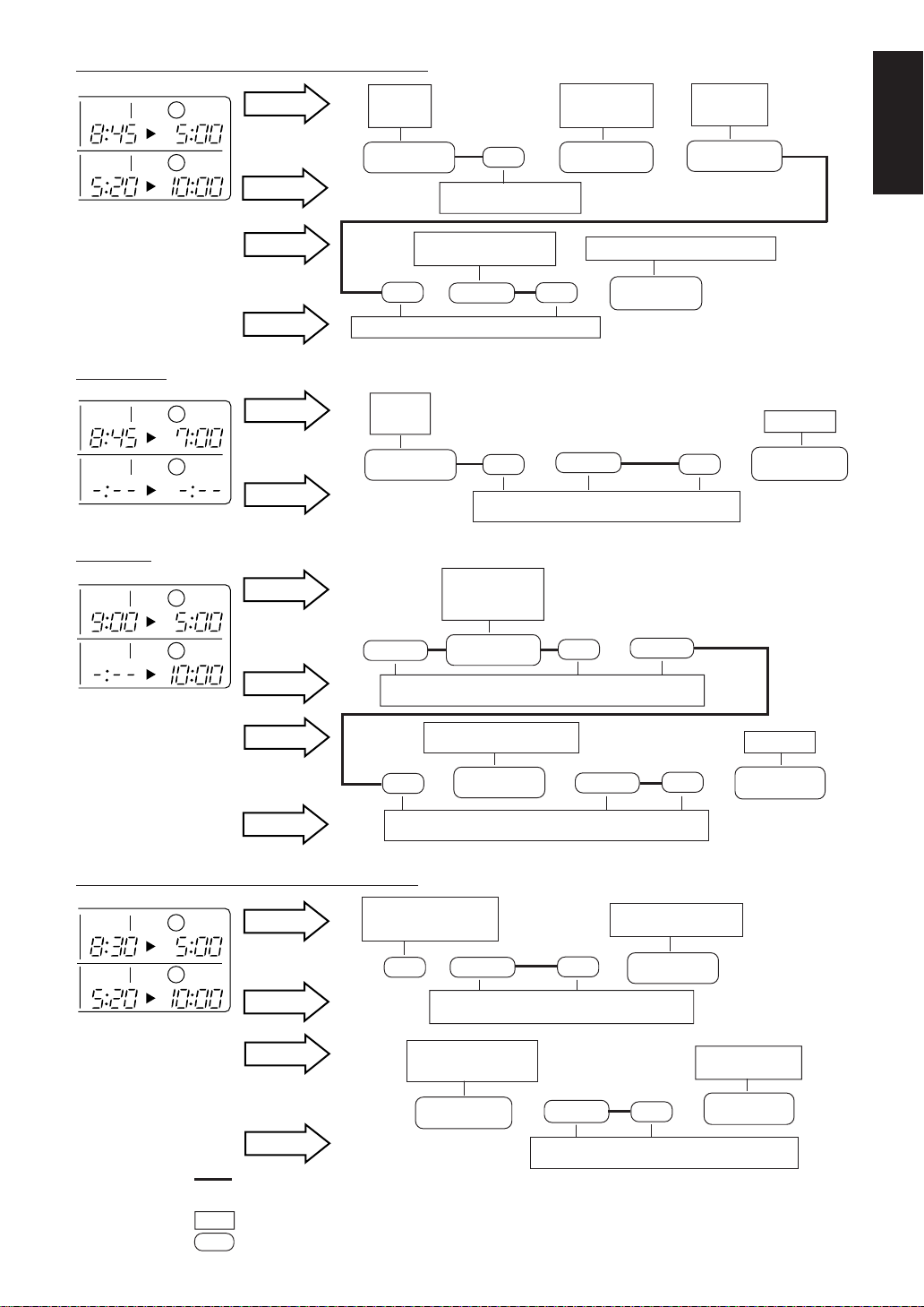
EXAMPLE OF OPERATION SCHEDULE
Liquid crystal display of schedule timer
ON/OFF control impossible by remote controller
Centralized
Remote
controller
Centralized
Operation
controlled
by timer
▼
Programmed
to operate at
8:45
Operation/stop by remote
controller cannot be made.
Forced and unified
Individual
stop
▼
Stop
stop. Power
reminder stops.
- - - - -
▼
Stop
Programmed
to stop at
5:00
When the operation, stop,
temperature setting and
operation mode setting
by remote controller are
rejected, “
HOST
is displayed on the remote
controller.
Operation schedule is possible only
in conjunction with the schedule
timer (optional accessory).
Stop
controlled
by timer
▼
Individual
operation
except for the
preset hours
- - -
▼
Operation
”
25
Page 10
OFFON
PMAM
SET1
OFFON
PMPM
SET2
OFFON
PMAM
SET1
OFFON
SET2
Only OFF control possible by remote controller
Centralized
Individual
SET1
SET2
- - -
▼
▲
Operation
controlled by
timer
▼
Programmed to
operate at 5:20
- - -
Stop
▲
Timer stops.
▼
Programmed to
stop at 7:00
ENGLISH
Centralized
Remote
controller
Centralized
Remote
controller
Centralized
Remote
controller
PMAM
PM
Centralized
Remote
controller
OFFON
OFFON
Operation
controlled
by timer
▼
Programmed to
operate at 8:45
Individual operation once
the unit is stopped.
- - -
Stop
▲
Only stopping possible by the remote controller.
Operation
controlled
by timer
▼
Programmed to
operate at 8:45
Operation
▲
Operation/stop is possible by the remote controller at any time
regardless of the hours programmed by the timer.
Stop
▲
Only stopping possible by
the remote controller.
▼
Operation
Stop
▲
Operation/stop is possible by the remote controller
during the hours programmed for timer operation.
Operation starts
without fail at the
timer-programmed
time.
▼
Programmed to
operate at 9:00
Timer stops even
if you forget to
turn off the unit.
- - -
Stop
▲
Operation
- - -
▼
Programmed to
stop at 5:00
Timer stops. Power reminder stops.
Programmed to
- - -
stop at 10:00
▲
Operation
- - -
Stop
▲
Centralized
Stop
▲
Remote
controller
Operation/stop is possible by the remote controller at any time
regardless of the hours programmed by the timer.
Timer operation possible by remote controller
Timer operation possible
SET1
SET2
OFFON
OFFON
- - - - -
Centralized
PMAM
PMPM
Remote
controller
Centralized
Remote
controller
Air conditioner now operating.
Air conditioner now stopping.
Command by central remote controller
Command by remote controller
by remote controller at
preset times.
▼
8:30
- - - - - - - - - - - - - - - - - - - - - - - - - - - - - - - - - - - - - - - - - -
- - - - - - - - -
- - - - - -
Stops temporarily at the
timer-programmed stop time.
▼
Programmed to
stop at 5:00
- - -
Operation
▲ ▲
Operation/stop is possible by the remote controller
during the hours programmed for timer operation.
Timer operation possible by remote controller
at preset times.
▼
Programmed to
operate at 5:20
- - -
Operation
Stops for a time at
timer-programmed time.
Stop
- - -
Operation
- - -
▲
Operation/stop is possible by the remote controller
during the hours programmed for timer operation.
Stop
▲▲
▼
Programmed to
stop at 5:00
- - -
Stop
▲
Timer stops.
▼
Programmed to
- - -- - -
stop at 10:00
- - - -
- - - - - - - -
Timer stops. Power
reminder stops.
▼
Programmed to
stop at 10:00
26
Page 11

SETTING OPERATION
MODE (Fig. 5)
● The Zone consists of the following
two cases.
A. Zone without display “ ”
The group with master remote controller setting
exists in this zone.
Setting the master remote controller enables cool/
heat selection.
Operations other than cool/heat operations can
also be set for some operations. For further
details, see the list on the right.
B. Zone with display “ ”
No group with master remote controller setting
exists in this zone.
The cool/heat selection is not available because
the master remote controller has not been set.
Some operations other than cool/heat operations
can be set. For further details, see the list in the
right.
See page 31 if the display “ ” is flashing.
1
Press the OPERATION MODE
SELECTOR BUTTON. Each time
you press this button, the display
rotates as shown on the right list.
NOTES
● During cool/heat operation, this central remote
controller enables FAN operation for each zone
even without setting the master remote controller.
Meanwhile, ventilation, ventilation/cleaning, etc. are
available, if UM etc. are connected with this unit in
the zone. See the operation manual provided with
the each unit.
● When the indoor unit is in heat operation, change
the setting to FAN operation through the central
remote controller; then, you can switch the fan
speed to the extremely low fan speed. Warm air
may blow if any other indoor unit belonging to the
same system is in heat operation.
● The indoor fan stops during defrost/hot start.
● DRY cannot be set from the central remote control-
ler.
● List of setting operation
A: Zones not displayed
Display Setting Contents of setting
▼
▼
▼
▼
▼
▼
▼
▼
— —
Display Setting Contents of setting
▼
▼
▼
▼
▼
▼
▼
▼
— —
Note) In the above list, “ 䡬 ” refers to the acceptable
setting, while “ ⳯ ” refers to the not acceptable
setting.
In the meanwhile, ❈1 and ❈2 refer to the
followings.
❈1: Setting may not be acceptable depending
⳯
䡬 To be set by zone
䡬
❈ 1
To be set by zone
䡬 To be set by zone
䡬 To be set by zone
䡬
䡬
To be set by zone
To be set by zone
❈ 1
❈ 1
Select this display if you
䡬 don’t wish to set by
zone.
B: Zones displayed
䡬 ❈ 2
䡬 To be set by zone
⳯
⳯
⳯
䡬
❈ 1
To be set by zone
䡬
❈ 1
Select this display if you
䡬 don’t wish to set by
zone.
on the type of indoor unit with which this
unit is connected.
27
Page 12

❈2: The group on FAN operation in the zone
performs the temperature control operation (cool/heat) under the outdoor
refrigerant system.
GROUP MONITORING
(Fig. 7)
TEMPERATURE SETTING
(Fig. 6)
1
Press the TEMPERATURE SET-
TING BUTTON.
°C.
°C.
▲
”, the
▼
”, the
Each time you press the “
temperature rises by 1
Each time you press the “
temperature falls by 1
If you don’t wish to set the temperature in a unified manner in the zone,
set the temperature to “ – – ”.
NOTES
● The setting temperature refers to that of the
temperature sensing part. (It may differ from
the room temperature.)
● The proper setting temperature is 26 – 28°C
during cooling operation, and 18 – 23°C during
heating operation.
● The setting temperature is not displayed in the
FAN mode and Ventilation/Cleaning mode. The
set temperature is not displayed either if UM
etc. form a zone without an air conditioner.
If you wish to set the temperature to
“ – – ”
(Example)
In case where the range of
No.
C
Set the temperature at the point 1°C higher than the
upper limit and 1°C lower than the lower limit of the
range subject to setting, respectively.
temperature to be set is 16
– 32°C
Press the “ ▼ ” when the
display shows 16°C. The
display “ – – ” appears.
Press the “ ▲ ” when the
display shows 32°C. The
display “ – – ” appears.
Utilize the group monitor function in each of the
following cases:
1. Check the malfunction code. (See the next
page.)
2. Check the group that requires cleaning of the
air filter and air cleaner element. (See page
30.)
3. Change the setting of the master remote
controller. (See page 29.)
4. Check the group(s) sharing the same outdoor
unit. Or, check the particular group(s) with the
master remote controller setting. (See page
30.)
5. Check the conditions of other individual
groups.
1
Press the ZONE/GROUP
CHANGEOVER BUTTON on the
display of zoning, and the display
“group” appears.
Unless operated from within one minute from
when the display of zoning appears, the display
will automatically revert back to the “group”
display.
2
Press the ADVANCE/BACKWARD BUTTON to set the group No.
Then, operation monitor display
“
” of group No. lights up in the
displayed zone; then, the state of
the above group(s) is displayed in
the liquid crystal display.
ENGLISH
28
Page 13

ERROR DIAGNOSING
FUNCTION (Fig. 8)
This central remote controller is provided with a
diagnosing function, for when an indoor unit stops due
to malfunction. In case of actuation of a safety
device, disconnection in transmission wiring for
control or failure of some parts, the operation lamp,
inspection display and unit No. start to flash; then, the
malfunction code is displayed. Check the contents of
the display, and contact your Panasonic dealer
because the above signs can give you the idea on the
trouble area.
The display “ ” flashes
under the group No. where
the indoor unit that has
stopped due to malfunction.
1
Press the RETURN/ADVANCE
BUTTON to call up the group that
has stopped due to malfunction.
The unit No. that has stopped due
to malfunction and the malfunction
code flash are displayed. The
display of control mode is replaced
by that of the unit No.
SETTING MASTER REMOTE
CONTROLLER (Fig. 9)
You must set the master remote controller of the
operation mode for one of the indoor units, if two or
more such indoor units with the remote controller are
connected with the outdoor unit where the operation
modes such as cool/heat operation and FAN operation
can be set by remote controller and central remote
controller.
1
● Check the particular group
with the master remote controller
setting for the refrigerant system
you wish to reset. (See the right.)
● Call up the group without the
display “
” (See page 30.)
Hold the OPERATION MODE SELECTOR BUTTON down for about four
seconds while the above group is
being called up.
The display “
” flashes on
the liquid crystal display of the
remote controller for all the groups
sharing the same outdoor unit or BS
unit.
When you turn on the power switch for the first
time, the display “ ” flashes.
2
Pall up the desired group to set
the master remote controller, and
press the OPERATION MODE SELECTOR BUTTON. The master
remote controller is set for this
group, and the display “
goes out. The display “
”
”
appears for the other groups.
Setting is finished now.
● In case of operation switch
Call up the zone including the group
with the setting of master remote
controller. (Zone without the display
“
”)
Press the OPERATION MODE SELECTOR BUTTON several times, and
switch to the desired operation mode.
Each time you press it, the display is
switched to “
” “ ” “ ” and
“ ––” in sequence.
NOTES
● Press the ZONE/GROUP CHANGEOVER BUTTON,
and call up the display of zoning.
● However, the displays “ ” “ ” and “ ”
may appear in some zones, depending on the type
of indoor unit with which they are connected.
29
Page 14

FUNCTION OF
07 09 10 11 12 13 14 15
REFRIGERANT SYSTEM
DISPLAY (Fig. 10)
The following information becomes available by
utilizing this function.
● Indoor group connected with the same outdoor unit
● Indoor group with the master remote controller
setting of the given refrigerant system
NOTES
● Unless operated from within one minute from
when the refrigerant system display, the display
will automatically revert back to the “group”
display.
● This function may not be available depending on
the type of outdoor unit with which the unit is
connected. In this case, the display “ ”
flashes.
REF.
CIRCUIT
ENGLISH
1
Press the ZONE/GROUP
CHANGEOVER BUTTON, and call up
the display “group” if the display of
zoning appears.
Unless operated from within one minute from
when the display of zoning appears, the display
will automatically revert back to the “group”
display.
2
Press the BUTTON FOR REFRIGERANT SYSTEM DISPLAY. The
display “ ” appears.
3
Press the ADVANCE/ BACK-
REF.
CIRCUIT
WARD BUTTON to call up the group
of which you wish to check the
refrigerant system.
00 01 02 03 04 05 06 07
1
2
3
“ ” of the particular group among them with the
master remote controller setting flashes. Repeat the
procedure 3 if you wish to check other refrigerant
systems as well.
The above example shows that the groups 1-00, 1-03,
1-05, 1-06, 1-07, 2-03 and 2-04 share the same
refrigerant system, and also that the master remote
controller is provided with group 1-03.
4
Press the BUTTON FOR RE-
The display “ ” of all the
groups sharing the same
refrigerant system as the
group on display flashes.
Then, the display
FRIGERANT SYSTEM DISPLAY
again. The display “ ” goes out.
REF.
CIRCUIT
The refrigerant system display is
finished now.
DISPLAY OF TIME TO
CLEAN (Fig. 11)
This central remote controller displays the time to
clean the air filter or air cleaner element for each
group or any given group by utilizing two types of
signs. The display “ ” tells the time to clean
the air filter or the air cleaner element of some group.
1
Press the ADVANCE/ BACKWARD BUTTON, and search the
groups displaying “
(The group may be plural.)
Clean or change the air filter or air cleaner
element.
For further details, see the operation manual
attached to each indoor unit. (Clean or change
the air filter or air cleaner element of all the
groups displaying “ ” or “ ”.)
2
Press the FILTER SIGN RESET
BUTTON, and the display “
disappears. (Including all the
groups where the air filter has been
cleaned.)
NOTE
Be sure to check the display “ ” has
disappeared at this point. The appearance of the
above display is a sign that the air filter or air cleaner
element of some group still needs cleaning.
” or “ ”
”
30
Page 15

UNIFIED OPERATION
(Fig. 12)
Use this function when executing operation and stop
of all the connected indoor units.
A
Unified operation
Press the UNIFIED OPERATION
BUTTON. All the displays “
the group No. in operation light up
at the same time, and all the groups
start to operate at the same time.
” of
MONITOR
00 01 02 03 04 05 06 07 08 09 10 1112 13 14 15
1
2
3
4
B
Unified stop
GROUP
Press the UNIFIED STOP BUTTON.
The lights of every display “
” of
group No. in operation go out at the
same time; then, the lights of all the
groups stop at the same time.
MONITOR
00 01 02 03 04 05 06 07 08 09 10 1112 13 14 15
1
2
3
4
GROUP
● When using the central remote controller in conjunction with other optional controllers for centralized
control, the OPERATION LAMP on controllers which
are not being used for operation may delay a few
minutes before lighting or going out.
There is nothing wrong with the equipment. The
delay is due to signal exchange.
31
Page 16

Installation table
When installing the equipment, mark the zone No. of each group and installation location in
the below table.
Setting group No.
(Setting is not possible unless power is activated to both the central
remote controller and indoor unit.)
Operated by remote controller
1. Activate power to both the central remote controller and indoor unit.
2. While in the normal mode, hold down the “
minimum of 4 seconds. The unified ON/OFF controller will enter the
FIELD SET MODE.
3. Select the MODE No. “ ” with the “ ” button.
4. Use the “ ” button to select the group No. for each group. (Group
No. increases in the order of 1-00, 1-01 ... 1-15, 2-00, ... 8-15.)
5. Press “ ” to set the selected group No.
6. Press “
GROUP NO.
” to return to the NORMAL MODE.
TEST
AIR CONDITIONER
▼
▼
▼
SETTING
5
TEST
4 3
2.6
” button for a
TEST
MODE NO.
FIELD SET
MODE
Operated by simplified remote controller
1. Activate power to both the central remote controller and indoor unit.
2. Remove the upper part of the remote controller.
3. Press the BS6 BUTTON (field set) on the PC board. The controller
will enter the FIELD SET MODE.
4. Select the MODE No. “ ” with the BS2 BUTTON and BS3
BUTTON (temperature setting).
5. Use the BS9 BUTTON (set A) and BS10 BUTTON (set B) to select
the group No. for each group. (Group No. increases in the order of 1-
00, 1-01 ... 1-15, 2-00, ... 8-15.)
6. Press BS7 BUTTON (set/cancel) to set the selected group No.
7. Press BS6 BUTTON (field set) to return to the NORMAL MODE.
BS1
MODE NO.
▼
UNIT
4
4
BS2
BS6 BS7 BS8 BS9 BS10
3・7
BS3
BS4
5
6
GROUP NO.
▼
BS5
5
ENGLISH
DEUTSCH
FRANÇAIS
ESPAÑOL
Zone No.
Group No.
Indoor unit
Quantity of units
Controlled by
Location
Zone No.
Group No. 2
Indoor unit
Quantity of units
Controlled by
Location
Zone No.
Group No. 3
Indoor unit
Quantity of units
Controlled by
Location
Zone No.
Group No. 4
Indoor unit
Quantity of units
Controlled by
Location
1–00 1–01 1–02 1–03 1–04 1–05 1–06 1–07 1–08 1–09 1–10 1–11 1–12 1–13 1–14 1–15
ITALIANO
–00 2–01 2–02 2–03 2–04 2–05 2–06 2–07 2–08 2 –09 2–10 2–11 2–12 2–13 2–14 2–15
VV
EVVHNIKA
–00 3–01 3–02 3–03 3–04 3–05 3–06 3–07 3–08 3 –09 3–10 3–11 3–12 3–13 3–14 3–15
NEDERLANDS
–00 4–01 4–02 4–03 4–04 4–05 4–06 4–07 4–08 4 –09 4–10 4–11 4–12 4–13 4–14 4–15
PORTUGUES
32
Page 17

Matsushita Electric Industrial Co., Ltd.
Web Site : http://www.panasonic.co.jp/global/
3VA10582-7A EM01A044 (0110) HT
 Loading...