

Panasonic CS-A9CKP, CS-A12CKP, CS-A7CKP, CU-A9CKP5, CU-A12CKP5 User Manual
...
9 Operating Instructions
AUT
AUT
DR
AN
COOL
AN
AUT
HEA
CS-A7CKP CU-A7CKP5 / CS-A9CKP CU-A9 CKP5 / CS-A12CKP CU- A12CKP5
SAFETY PRECAUTIONS
Before operating, please read the following
“Safety Precautions” carefully.
● To prevent personal injury, injury to others and
property damage, the following instructions must be
followed.
● Incorrect operation due to failure to follow instructions
will cause harm or damage, the seriousness of which
is classified as follow:
!
This sign warns of death or serious injury.
This sign warns of damage to property.
● The instructions to be followed are classified by the
following symbols:
This symbol (with a white background) denotes an
These symbols (with a black background) denote
Warning
!
Caution
action that is PROHIBITED.
F
F
O
actions that are COMPULSORY.
■ Installation Precautions
!
Warning
● Do not install, remove and reinstall the unit by
yourself.
Improper installation will cause leakage, electric
shock or fire. Please engage an authorized dealer
or specialist for the installation work.
!
Caution
● This room air conditioner must be
earthed.
Improper grounding could cause
electric shock.
● Ensure that the drainage piping is
connected properly.
Otherwise, water will leak out.
● Do not install the unit in a
potentially explosive atmosphere.
Gas leak near the unit could cause
fire.
■ Operation Precautions
!
This sign warns of death or serious injury.
● Do not share outlet.
● Do not insert plug to operate the unit. Do not
● Do not operate with wet hands.
● Do not damage or modify the power cord.
● Do not insert finger or other objects into the
● Do not expose directly to cold air for a long
● Plug in properly.
● Use specified power cord.
F
F
O
● If abnormal condition (burnt smell, etc.)
● Do not pull the cord to disconnect the plug.
● Do not wash the unit with water.
● Do not use for other purposes such as
● Do not use any combustible equipment at
● Do not sit or place anything on the outdoor
● Switch off the power supply before cleaning.
● Ventilate the room regularly.
● Pay attention as to whether the installation
F
F
O
● Switch off the power supply if the unit is not
Warning
pull out plug to stop the unit.
indoor or outdoor units.
period.
occurs, switch off and unplug the power
supply.
!
Caution
This sign warns of injury.
preservation.
airflow direction.
unit.
rack is damaged after long period of usage.
used for a long period.
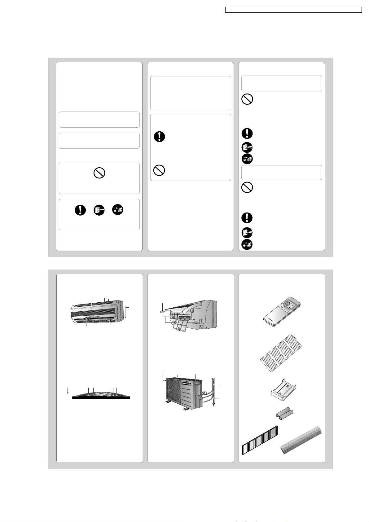
NAME OF EACH PART
■ Indoor Unit
1
2
4576
1 Front Panel
2 Air Intake Vent
3 Power Supply Cord
4 Air Outlet Vent
5 Vertical Airflow Direction Louver
6 Horizontal Airflow Direction Louver
(manually adjusted)
7 Indicator Panel
1 23 654
1 Auto Operation Button
(when the front panel is opened)
2 Powerful Mode Indicator – ORANGE
3 Ionizer Mode Indicator – GREEN
4 Power Indicator – GREEN
5 Quiet Mode Indicator – ORANGE
6 Timer Mode Indicator – ORANGE
● Indoor Unit
(when the front panel is opened)
1
3
3
2
■ Accessories
● Remote Control
AU
T
O
H
E
A
T
O
N
O
F
F
A
U
FA
T
T
O
E
N
M
P
M
O
D
E
O
A
F
E
I
F
R
C
/
O
S
O
S
te
N
N
W
O
p
I
M
N
Y
G
1
O
N
S
L
E
E
O
P
2
F
F
F
A
N
S
PE
E
D
C
3
H
E
T
C
S
IM
K
E
R
E
T
E
R
S
E
T
C
A
C
N
L
O
C
C
E
K
L
+
B
A
T
T
E
R
Y
C
OO
L
A
D
U
T
R
O
YFA
N
● Remote Control Indication Sticker
1 Front Panel
2 Air Filters
3 Air Purifying Filter
■ Outdoor Unit
1
6
1 Air Intake Vents
2 Ground Terminal
(Inside cover)
3 Piping
4 Connecting Cable
5 Drain Hose
6 Air Outlet Vents
2
● Remote Control Holder
3
4
5
● Two RO3 (AAA) dry-cell batteries or equivalent
● Air Purifying Filter
(Catechin Air
Purifying Filter)
(Triple Deodorizing
Filter)
39
CHECK
TEMP
AUTO
ON
OFF
AUTAUTO DRDRYFANANCOOLCOOL
FAN
AUTO
RESET CLOCK
MODE
POWERFUL
QUIET
FAN SPEED
AIR SWING
OFF
CANCEL
ON
SET
1
2
3
TIMER
OFF/ON
AUTO
MANUAL
#
!
$
%
^
$
*
&
3
5
8
7
9
0
6
4
(
HEA
CHECK
AUTO
O
F
AUTOHEAT
DRY
FANCOOL
FAN
AUTO
AUTO
RESET
CLOCK
A
IR
S
W
I
N
G
OFF
C
A
N
C
E
L
1
2
3
T
IM
E
R
POW
ERFUL
A
U
T
O
M
A
N
U
A
L
EC
O
N
O
M
Y
S
L
E
O
N
S
E
T
FAN SPEED
M
O
D
E
2
1
1.5V
1.5V
CHECK
AUTO
AUTO HEAT DRY FANCOOL
FAN
AUTO
RESET CLOCK
FAN SPEED
AIR SWING
OFF
CANCEL
ON
SET
1
2
3
TIMER
AUTO
MANUAL
1
2
O
F
F
O
N
H
E
A
HEAT
DRDRY
FA
N
ANC
O
O
L
COOL
CHECK
T
E
M
P
A
U
T
AUTO
A
UT
AUTO
FA
N
AN
A
U
T
AUTO
RESET
CLOCK
A
IR
S
W
IN
G
OFF
C
A
NC
E
L
1
2
3
TIM
ER
O
FF/
ON
A
U
TO
M
ANU
A
L
Q
U
I
E
T
POWERFUL
ON
S
E
T
FAN SPEED
M
O
DE
CS-A7CKP CU-A7CKP5 / CS-A9CKP CU-A9 CKP5 / CS-A12CKP CU- A12CKP5
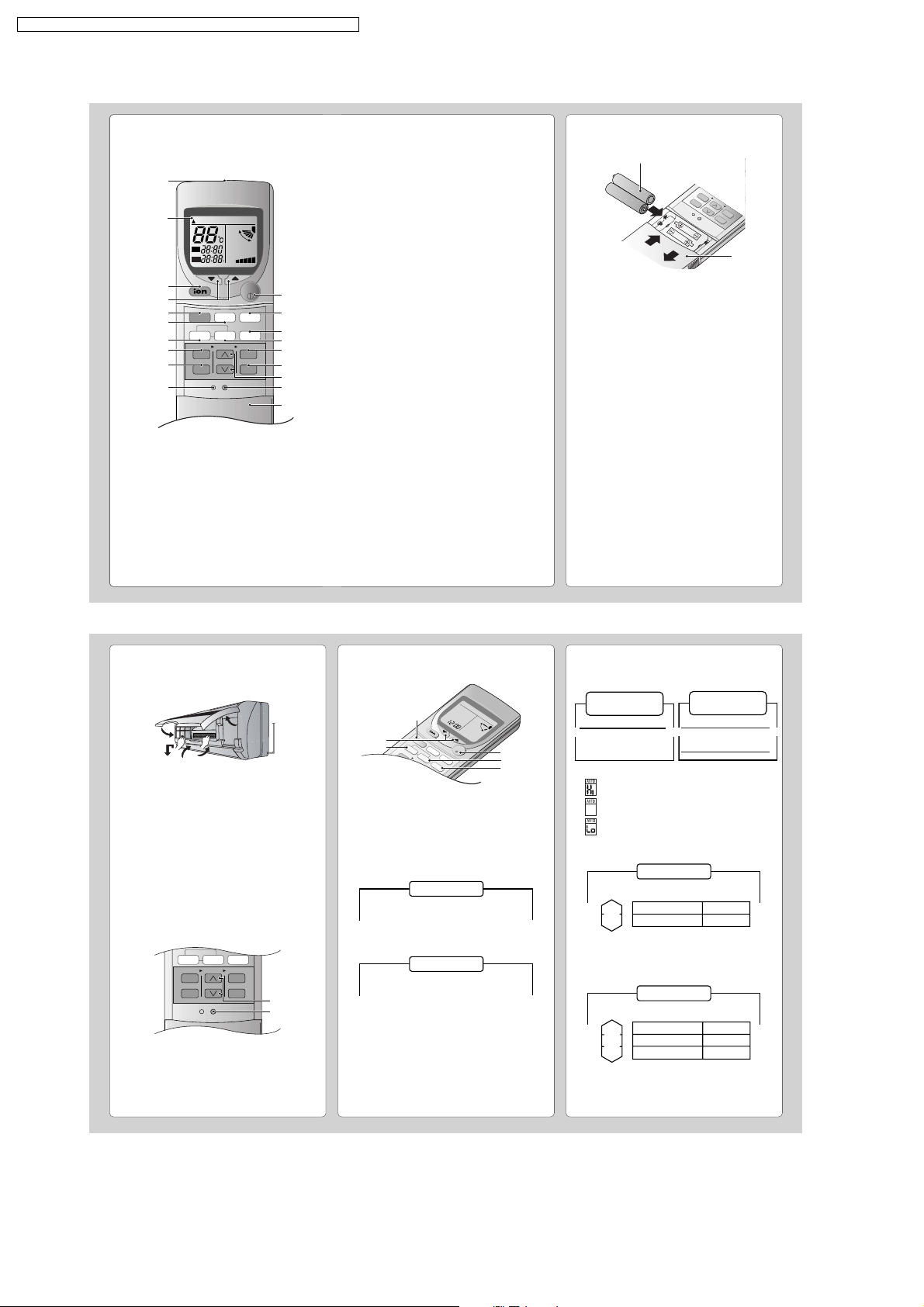
NAME OF EACH PART
■ Remote Control
1
2
● Remote Control Signal.
• Make sure it is not obstructed.
• Maximum distance : 10 m.
• Signal received sound.
One short beep or one long beep.
● Notes for Remote Control.
• Do not throw or drop.
• Do not get it wet.
• Certain type of fluorescent lamps may affect
signal reception. Consult your dealer.
HEA
T
1 Signal Transmitter
2 Operation Display
3 Ionizer Mode Operation Button
4 Room Temperature Setting Button
(illuminating button)
5 Operation Mode Selection Button
6 Quiet Mode Operation Button
7 Auto Airflow Direction Button
8 ON-Timer Button
9 OFF-Timer Button
0 Reset Point
(Press with fine-tipped object to clear the memory)
! OFF/ON Button
(illuminating button)
@ Powerful Mode Operation Button
# Fan Speed Selection Button
$ Manual Airflow Direction Selection Button
% Timer Set Button
^ Timer Cancellation Button
& Time-Setting Button
* Clock Button
( Remote Control Cover
● How to Insert the Batteries
1
Slide down the remote control cover completely
2
Insert the batteries
– Be sure the direction is correct
– 12.00 at display - flashing
• Set the current time (CLOCK) immediately to
prevent battery exhaustion.
● About the batteries
• Can be used for approximately one year.
● Observe the following when replacing the
batteries
• Replace with new batteries of the same type.
• Do not use rechargeable batteries (Ni-Cd).
• Remove the batteries if the unit is not going to be
used for a long period.
PREPARATION BEFORE OPERATION
HOW TO OPERATE
■ Indoor Unit
1
2
6
3
5
4
1
Connect the power supply cord to an independent
power supply
2
Open the front panel
3
Remove the air filters
4
Fit the air purifying filters in place
5
Insert the air filters
6
Close the front panel
■ Remote Control
– To set the current time
1
Press 1.
2
Then press 2 to increase or decrease the time.
3
Press 1 again.
Set time at display will light up.
■ To start the operation
• Press 1.
• POWER indicator (green) on the indoor unit will light
up.
• To stop, press once more.
■ Setting Mode
• Press 2 to select:-
2
3
5
Cooling Model
AUTO – Automatic Operation
COOL – Cooling Operation
DRY – Soft Dry Operation
FAN – Air Circulation Operation
Heat Pump Model
AUTO – Automatic Operation
HEAT – Heating Operation
COOL – Cooling Operation
DRY – Soft Dry Operation
40
1
6
4
■ Setting Temperature
• Press 3 to increase or decrease the temperature.
• The temperature can be set between 16°C ~ 30°C.
• Recommended temperature:
Cooling Model
COOL –> 26°C ~ 28°C
DRY –> 1°C ~ 2°C
lower than the
room temperature
Heat Pump Model
COOL – > 26°C ~ 28°C
DRY –> 1°C ~ 2°C
lower than the
room temperature
HEAT –> 20°C ~ 24°C
• During AUTO Operation, press 3 to select:-
• Operation with 2°C higher than the standard
temperature.
• Operation with the standard temperature.
• Operation with 2°C lower than the standard
temperature.
● Standard Temperature
Cooling Model
Indoor
temperature
23°C
• Once the Automatic Operation is selected, the indoor
temperature sensor operates automatically to select
the desired operation mode with Cooling or Soft Dry.
• After the operation mode has been selected, the
mode does not change.
Indoor
temperature
23°C
20°C
• At the beginning of the automatic operation, Heating,
Cooling or Soft Dry is automatically selected according
to the indoor temperature.
• The operation mode changes every hour, when
necessary.
Operation
Cooling
Soft Dry
Heat Pump Model
Operation
Cooling
Soft Dry
Heating
Standard
temperature
25°C
22°C
Standard
temperature
25°C
22°C
21°C
 Loading...