

Panasonic CU-4KS31NBU User Manual
TECHNICAL & SERVICE MANUAL
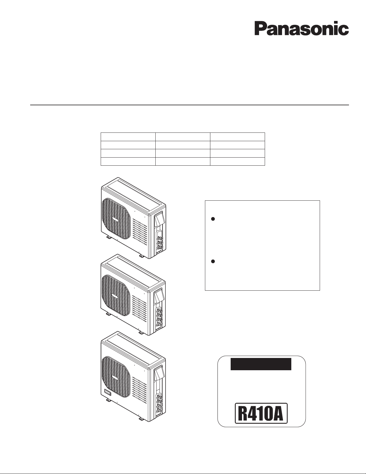
OUTDOOR UNIT : CU-3KS19NBU
CU-4KS24NBU
CU-4KS31NBU
DC INVERTER MULTI-SYSTEM AIR CONDITIONER
CU-3KS19NBU
CU-4KS24NBU
Capacity at 230V
19,700 BTU/h
25,400 BTU/h
30,600 BTU/h
Outdoor Model No.
CU-3KS19NBU
CU-4KS24NBU
CU-4KS31NBU
Product Code No.
1 852 361 24
1 852 361 25
1 852 361 26
< Applicable Indoor Units >
Wall mounted type
CS-MKS7NKU
CS-MKS9NKU
CS-MKS12NKU
CS-MKS18NKU
CS-MKS24NKU
Semi-concealed type
CS-MKS9NB4U & CZ-18BT1U
CS-MKS12NB4U & CZ-18BT1U
CS-KS18NB4UW & CZ-18BT1U
CU-4KS31NBU
IMPORTANT
These air conditioners employ new
refrigerant R410A.
Pay special attention when
servicing the unit.
REFERENCE NO.
SM700877
SAFETY PRECAUTIONS
• Before doing repair work, please read the " SAFETY PRECAUTIONS" carefully and fully understand them.
• The precautionary items here are divided into " Warning" and " Caution" items.
Items in particular which may cause death or serious injury to the service personnel if the work is not performed correctly,
are included in the " Warning" table.
However, even precautionary items identified as " Caution" also have the potential for serious consequences
if not performed correctly.
Important safety precautions are described for all items in both categories. Be sure to carefully follow all of them.
• Symbol Indication
: This symbol indicates items to which we need to pay attention.
In this triangle, a definite precautionary item is described.
: This symbol indicates the item to be prohibited.
In or close to this circle, a prohibited item is described.
: This symbol indicates the items requiring special attention or instruction.
In or close to this circle, a prohibited item is described.
• After doing repair work, perform a test run to confirm that there are no abnormalities.
At the same time, explain the precautions in use to the user.
Warning
Before performing an overhaul, disconnect the power plug or power cable from the unit.
Performing the work with the power supplied to the unit, may cause an electric shock.
When repair work or circuit inspection that requires power supply for the air conditioner, is to be performed,
do not touch the charging section.
Doing so may cause an electric shock.
Prohibit
For the step-up capacitor attached to the electric section, perform the repair work after sufficiently discharging it.
Insufficient capacitor discharge may cause an electric shock.
Do not perform repair work on the electric sections with wet hands.
Doing so may cause an electric shock.
Do not start or stop the air conditioner by means of connecting or disconnecting the power plug.
Doing so may cause an electric shock or fire.
When conducting repair work only use components included in the parts list for the corresponding unit and perform
the work with the appropriate tools.
Incorrect or poor repair work may cause an electric shock or fire.
Never modify the unit.
Doing so may cause an electric shock or fire.
Perform all electric work according to local applicable regulations related to electrical equipment or interior wiring
regulation and make sure to use the exclusive circuit.
Insufficient capacity to the electric circuit or defective arrangement results may cause an electric shock or fire.
Make sure to replace any power cable or lead wire showing any signs of scratch or deterioration.
Failure to do so may cause an electric shock, overheating or fire.
Make sure that there is no dust on or slack in the power plug and insert fully into the socket.
Dust or incomplete connections may cause an electric shock or fire.
Do not damage or process the power cord, as it may cause an electric shock or fire.
Prohibit
Prohibit
Prohibit
Prohibit
For the wiring between the indoor unit and outdoor unit, securely fix the specified cable onto the terminal plate.
Poorly fixed wiring may cause a heat or fire.
After connecting the wiring between the indoor unit and outdoor unit, attach the terminal cover securely.
Incomplete attachment of the terminal cover may cause overheating or fire.
2
Warning
If refrigerant gas blows off during the work, do not touch the refrigerant gas as it may cause frostbite.
If refrigerant gas leaks during the work, ventilate the room.
If refrigerant gas catches fire, harmful gas may be generated.
Do not mix any gas other than the specified refrigerant gas in the refrigerating cycle.
If air or other contaminants mix with the gas, pressure will become extremely high in the refrigerating cycle,
which may cause a unit breakdown."
When the welded section of the compressor intake or discharge pipe is to be disconnected, perform it in
a well-ventilated place after sufficiently recovering the refrigerant gas.
Any residue gas may jet out refrigerant or refrigerating machine oil, which may cause an injury.
When the work is to be performed in a high place (About 2 meters or more), make sure to wear a safety helmet,
gloves and safety belt. Insufficient safety gear may cause a serious injury in case of a fall.
When the unit is to be relocated, confirm that the new installation location has sufficient strength for the weight of the unit.
Insufficient strength of the installation location and incomplete installation work may cause an injury due to
the unit falling.
When the remote controller batteries are replaced, dispose of the old batteries out of the reach of children.
If a child swallows a battery, make sure that the child gets immediate medical attention.
Caution
Prohibit
Prohibit
Do not wash the air conditioner with water, as this may cause an electric shock or fire.
For the repair work in places with high humidity or moisture, make sure to ground the unit.
Failure to do so may cause an electric shock.
Confirm that the component attachment position, wiring condition, soldering condition and connector connection
are normal.
If not, it may cause overheating or fire.
Confirm that the temperature around the compressor is not too high, and then perform the repair work.
Failure to do so may cause a burn.
Perform welding work in a place with good ventilation.
If the work is performed in a poorly ventilated area, it might cause a lack of oxygen.
If the installation plate or attachment frame has deteriorated due to corrosion, etc., replace it.
Failure to do so may cause an injury due to the unit falling.
When the cleaning is to be performed, make sure to turn off the power and pull out the plug.
Touching the fan that is rotating at high speed may result in an injury.
When the indoor unit is to be removed, do not place it on an incline.
Doing so may cause wet furniture because water left inside may trickle down.
Do not hold the sharp end of the unit or the aluminum fins, as it may cause an injury to your hand or finger.
Prohibit
Prohibit
Prohibit
After repairs, make sure to measure the insulation resistance and confirm that the value is 1 Mohm or more.
Any insulation error may cause an electric shock.
After repairs, make sure to check the drainage of the indoor unit.
Inappropriate drainage may cause wet furniture and floors due to water leakage.
3

SAFETY PRECAUTIONS
Table of Contents
Page
..............................................................................................................
2
TABLE OF CONTENTS
APPLICABLE INDOOR UNITS
1. OPERATING RANGE
2. SPECIFICATIONS
2-1. Unit Specifications
2-2. Major Component Specifications
2-3. Other Component Specifications
3. DIMENSIONAL DATA
4. REFRIGERANT FLOW DIAGRAM
4-1. Refrigerant Flow Diagram
5. PERFORMANCE DATA
5-1. Temperature Charts
5-2. Cooling Capacity
5-3. Cooling Capacity (Low Ambient)
......................................................................................................................
.....................................................................................................
...................................................................................................................
.............................................................................................................
...................................................................................................................
............................................................................................................
................................................................................................................
.......................................................................................
.......................................................................................
...................................................................................................
........................................................................................
4
6
7
8
17
20
21
24
27
50
56
6. ELECTRICAL DATA
6-1. Electric Wiring Diagrams
7. FUNCTIONS
7-1. Explanation of Functions
7-2. Protective Functions
8. TROUBLESHOOTING (BEFORE CALLING FOR SERVICE)
8-1. Precautions before Performing Inspection or Repair
8-2. Trouble Diagnosis by Error Monitop Lamps
8-3. Checking the Outdoor System
8-4. Trouble Diagnosis of Each Part
8-5. Trouble Diagnosis of Fan Motor
....................................................................................................
.....................................................................................................
...........................................................................................................
.......................................................................
...........................................................................................
.........................................................................................
.........................................................................................
..........................................................
62
65
69
71
72
73
74
78
4

9. REFRIGERANT R410A:
SPECIAL PRECAUTIONS WHEN SERVICING UNIT
9-1. Characteristics of New Refrigerant R410A
9-2. Checklist before Servicing
9-3. Tools Specifically for R410A
9-4. Tubing Installation Procedures
9-5. In Case of Compressor Malfunction
9-6. In Case Refrigerant is Leaking
9-7. Charging Additional Refrigerant
9-8. Retro-Fitting Existing Systems
...................................................................................................
................................................................................................
............................................................................................
....................................................................................
............................................................................................
..........................................................................................
............................................................................................
Page
.........................................................................
79
80
81
81
82
84
85
85
APPENDIX A INSTALLATION INSTRUCTIONS
.............................................................................
A-1
5
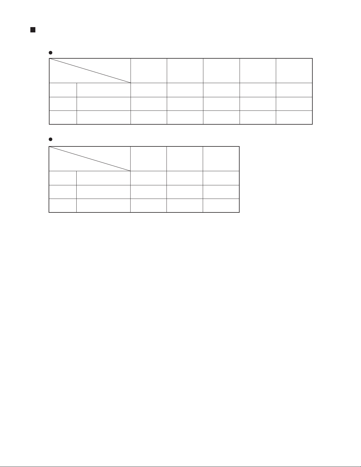
APPLICABLE INDOOR UNITS
Wall Mounted Type
Indoor Unit
CS-MKS7NKU
Multi-Outdoor Unit
CS-MKS9NKU CS-MKS12NKU CS-MKS18NKU CS-MKS24NKU
3-Room
4-Room
4-Room
CU-3KS19NBU
CU-4KS24NBU
CU-4KS31NBU
Semi-Concealed Type
Indoor Unit
Multi-Outdoor Unit
3-Room
4-Room
4-Room
CU-3KS19NBU
CU-4KS24NBU
CU-4KS31NBU
YES
YES
YES
CS-MKS9NB4U
&
CZ-18BT1U
YES
YES
YES
YES
YES
YES
CS-MKS12NB4U
&
CZ-18BT1U
YES
YES
YES
YES
YES
YES
CS-KS18NB4UW
&
CZ-18BT1U
YES
YES
YES
YES
YES
YES
NO
YES
YES
6

1. OPERATING RANGE
Temperature Indoor Air Intake Temp. Outdoor Air Intake Temp.
Cooling
Maximum
Minimum
95 °F DB / 71 °F WB
67 °F DB / 57 °F WB
115 °F DB
14 °F DB
7
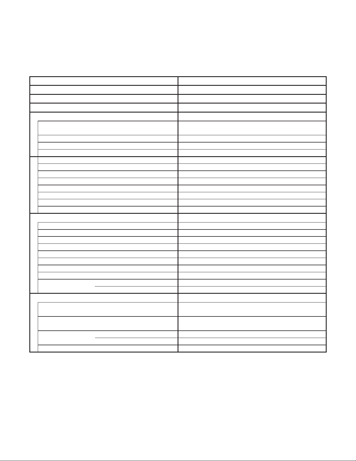
2. SPECIFICATIONS
2-1. Unit Specifications
Outdoor Unit CU-3KS19NBU
Indoor Unit CS-MKS9NKU × 2
Duct Less Type Rated
Type
Total Capacity
Sensible Capacity
Latent Capacity
Performance
Available Voltage Range
Running Amperes
EER BTU/h/W 12.0
SEER BTU/Wh 18.0
Compressor Locked Rotor Amperes
Electrical Rating
Fuse or Circuit Breaker Capacity A 15
Control Microprocessor
Fan Speeds Auto (Hi, Me, Lo)
Compressor
Refrigerant / Amount charged at shipment Ibs (g)
Refrigerant Control
Operation Sound (High) Cool
Features
Refrigerant Tubing Connections
Max. allowable tubing length per unit
Refrigerant inch (mm)
Tube Diameter inch (mm)
Unit Dimensions
Height × Width × Depth
Package Dimensions
Height × Width × Depth
Weight
Dimensions & Weight
Shipping Volume
Remarks:
1. The values shown in performance section and electrical rating section above are based on the following unit combination.
For other combination unit, please refer to the "Unit Combination Tables" in this manual.
Indoor Unit : CS-MKS9NKU 2units Outdoor Unit : CU-3KS19NBU 1unit
The combination indoor unit is AHRI 210/240.
2. Rating conditions are: Cooling : Indoor air temp. 80 °F DB / 67 °F WB
Outdoor air temp. 95 °F DB / 75 °F WB
Narrow tube
Wide tube
Net
Shipping
BTU/h
kW
BTU/h
BTU/h
V
A
WPower Input
%Power Factor 98
A 13.0
dB-A
ft (m)
inch
(mm)
inch
(mm)
Ibs (kg)
Ibs (kg)
cu.ft (m3)
3-Room Multi Outdoor Unit
3Number of Connectable Indoor Units
3Number of Operatable Indoor Units
230V Single-Phase 60HzVoltage Rating
Cooling
17,000
29-1/8 × 35-7/16 × 12-19/32
34-3/16 × 41-11/32 × 16-21/32
DATA SUBJECT TO CHANGE WITHOUT NOTICE.
( 6,800 to 18,800 )
5.00
( 1.90 to 5.50 )
14,300
2,700
1,707 (2,900)Air Circulation (High) ft3/min (m3/h)
187 to 253
6.3
1,420
Outdoor Unit
DC Twin Rotary (Inverter)
R410A / 6.17 (2,800)
Electric Expansion Valve
50
Flare Type
82 (25)
1/4 (6.35) × 3
3/8 (9.52) × 3
Outdoor Unit
(740 × 900 × 320)
(868 × 1,050 × 423)
138.9
(63.0)
147.7
(67.0)
13.41 (0.38)
< 230V >
8

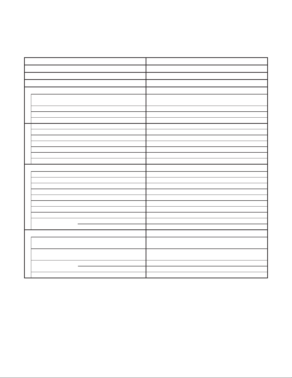
Outdoor Unit CU-3KS19NBU
Indoor Unit CS-MKS9NKU ×
Type
Total Capacity
Sensible Capacity
Latent Capacity
Performance
Available Voltage Range
Running Amperes
EER BTU/h/W 12.5
Compressor Locked Rotor Amperes
Electrical Rating
Fuse or Circuit Breaker Capacity A 15
Control Microprocessor
Fan Speeds Auto (Hi, Me, Lo)
Compressor
Refrigerant / Amount charged at shipment Ibs (g)
Refrigerant Control
Operation Sound (High) Cool
Features
Refrigerant Tubing Connections
Max. allowable tubing length per unit
Refrigerant inch (mm)
Tube Diameter inch (mm)
Unit Dimensions
Height × Width × Depth
Package Dimensions
Height × Width × Depth
Weight
Dimensions & Weight
Shipping Volume
3
Narrow tube
Wide tube
Net
Shipping
BTU/h
kW
BTU/h
BTU/h
V
A
WPower Input
%Power Factor 98
A 13.0
dB-A
ft (m)
inch
(mm)
inch
(mm)
Ibs (kg)
Ibs (kg)
cu.ft (m3)
34-3/16 × 41-11/32 × 16-21/32
DATA SUBJECT TO CHANGE WITHOUT NOTICE.
3-Room Multi Outdoor Unit
230V Single-Phase 60HzVoltage Rating
Cooling
18,800
29-1/8 × 35-7/16 × 12-19/32
( 9,800 to 18,800 )
5.50
( 2.90 to 5.50 )
16,000
1,707 (2,900)Air Circulation (High) ft3/min (m3/h)
187 to 253
1,500
Outdoor Unit
DC Twin Rotary (Inverter)
R410A / 6.17 (2,800)
Electric Expansion Valve
Flare Type
82 (25)
1/4 (6.35) × 3
3/8 (9.52) × 3
Outdoor Unit
(740 × 900 × 320)
(868 × 1,050 × 423)
138.9
147.7
13.41 (0.38)
< 230V >
3Number of Connectable Indoor Units
3Number of Operatable Indoor Units
2,800
6.7
50
(63.0)
(67.0)
Remarks:
1. The values shown in performance section and electrical rating section above are based on the following unit combination.
For other combination unit, please refer to the "Unit Combination Tables" in this manual.
Indoor Unit : CS-MKS9NKU 3units Outdoor Unit : CU-3KS19NBU 1unit
2. Rating conditions are: Cooling : Indoor air temp. 80 °F DB / 67 °F WB
Outdoor air temp. 95 °F DB / 75 °F WB
9
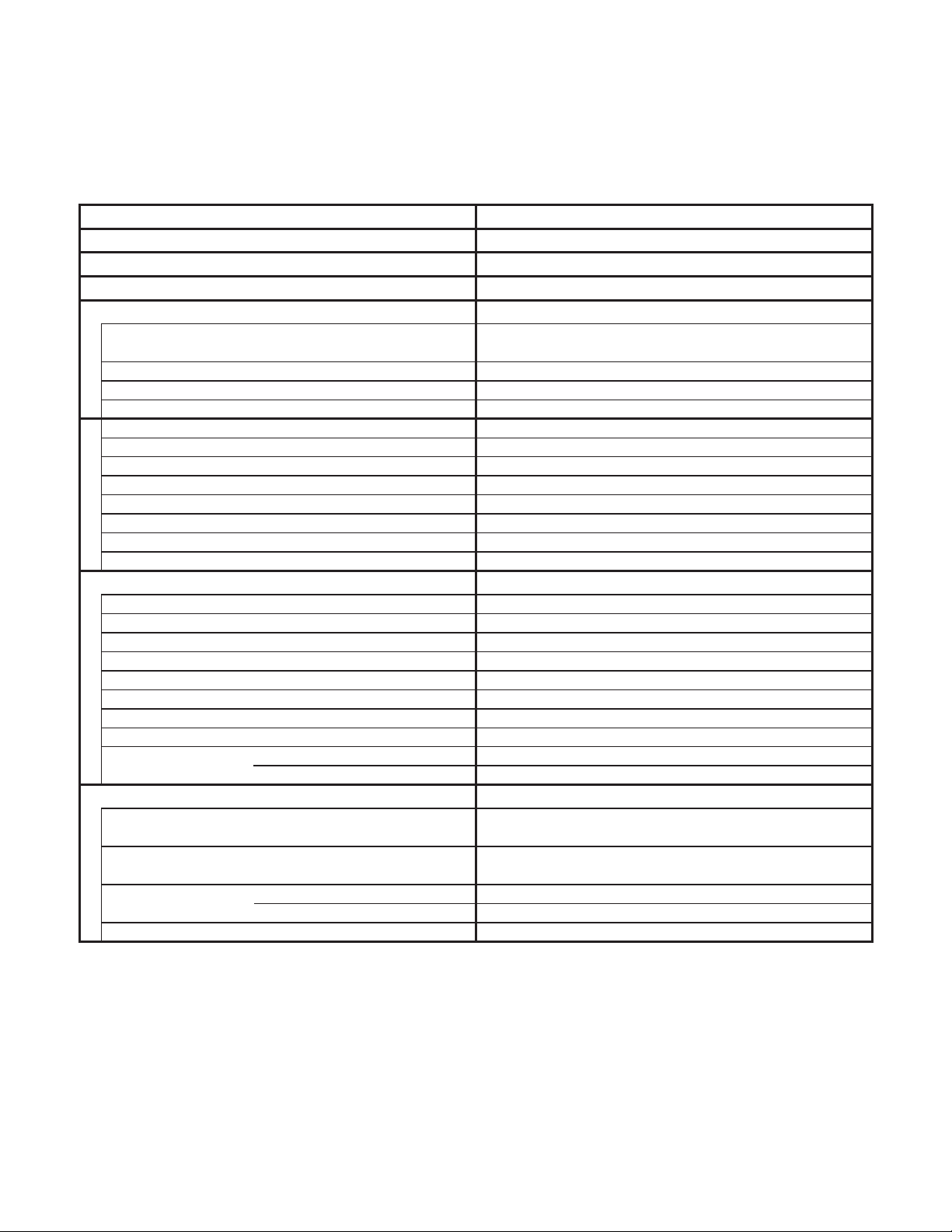
Outdoor Unit CU-3KS19NBU
Indoor Unit CS-MKS9NKU ×
Type
Total Capacity
Sensible Capacity
Latent Capacity
Performance
Available Voltage Range
Running Amperes
EER BTU/h/W 12.5
Compressor Locked Rotor Amperes
Electrical Rating
Fuse or Circuit Breaker Capacity A 15
Control Microprocessor
Fan Speeds Auto (Hi, Me, Lo)
Compressor
Refrigerant / Amount charged at shipment Ibs (g)
Refrigerant Control
Operation Sound (High) Cool
Features
Refrigerant Tubing Connections
Max. allowable tubing length per unit
Refrigerant inch (mm)
Tube Diameter inch (mm)
Unit Dimensions
Height × Width × Depth
Package Dimensions
Height × Width × Depth
Weight
Dimensions & Weight
Shipping Volume
3
Narrow tube
Wide tube
Net
Shipping
BTU/h
kW
BTU/h
BTU/h
V
A
WPower Input
%Power Factor 98
A 13.0
dB-A
ft (m)
inch
(mm)
inch
(mm)
Ibs (kg)
Ibs (kg)
cu.ft (m
3
)
34-3/16 × 41-11/32 × 16-21/32
DATA SUBJECT TO CHANGE WITHOUT NOTICE.
3-Room Multi Outdoor Unit
208V Single-Phase 60HzVoltage Rating
Cooling
18,800
29-1/8 × 35-7/16 × 12-19/32
( 9,800 to 18,800 )
5.50
( 2.90 to 5.50 )
16,000
1,707 (2,900)Air Circulation (High) ft3/min (m3/h)
187 to 253
1,500
Outdoor Unit
DC Twin Rotary (Inverter)
R410A / 6.17 (2,800)
Electric Expansion Valve
Flare Type
82 (25)
1/4 (6.35) × 3
3/8 (9.52) × 3
Outdoor Unit
(740 × 900 × 320)
(868 × 1,050 × 423)
138.9
147.7
13.41 (0.38)
< 208V >
3Number of Connectable Indoor Units
3Number of Operatable Indoor Units
2,800
7.4
50
(63.0)
(67.0)
Remarks:
1. The values shown in performance section and electrical rating section above are based on the following unit combination.
For other combination unit, please refer to the "Unit Combination Tables" in this manual.
Indoor Unit : CS-MKS9NKU 3units Outdoor Unit : CU-3KS19NBU 1unit
2. Rating conditions are: Cooling : Indoor air temp. 80 °F DB / 67 °F WB
Outdoor air temp. 95 °F DB / 75 °F WB
10
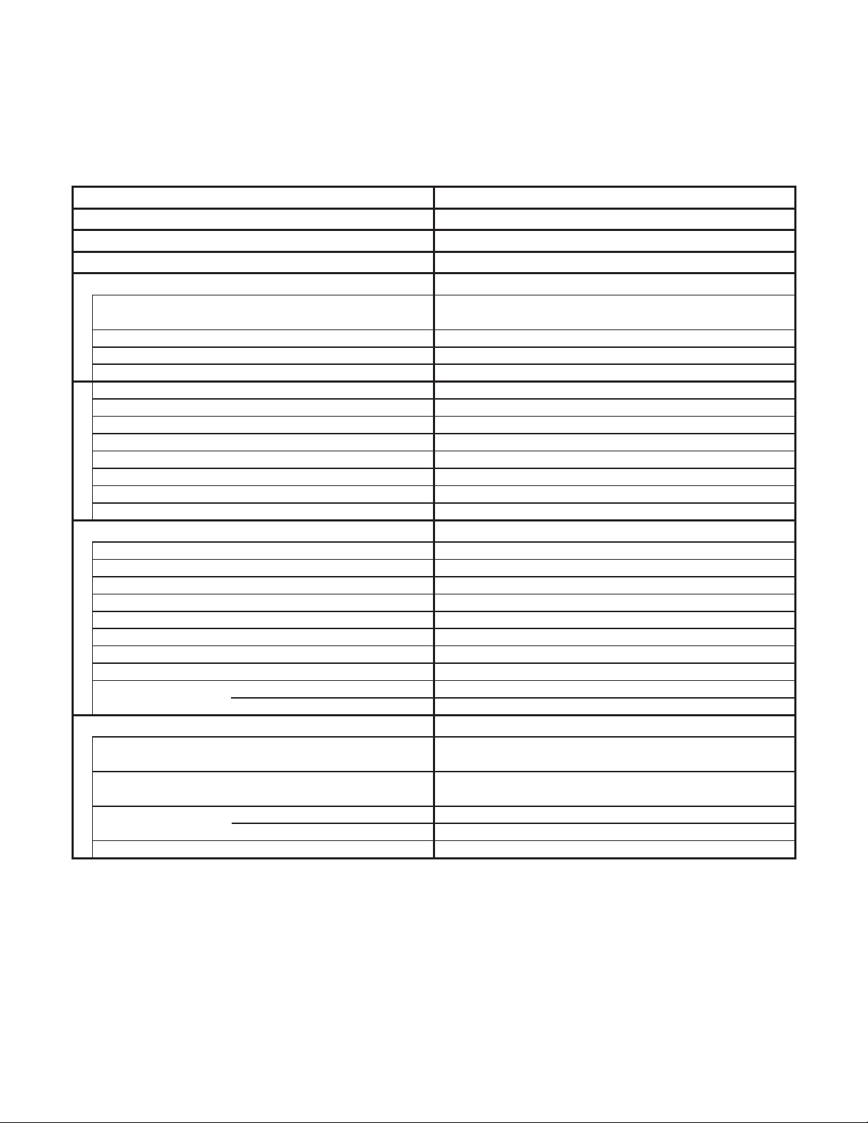
Outdoor Unit CU-4KS24NBU
Indoor Unit CS-MKS7NKU + CS-MKS9NKU × 2
Duct Less Type Rated
Type
Total Capacity
Sensible Capacity
Latent Capacity
Performance
Available Voltage Range
Running Amperes
EER BTU/h/W 10.0
SEER BTU/Wh 18.0
Compressor Locked Rotor Amperes
Electrical Rating
Fuse or Circuit Breaker Capacity A 20
Control Microprocessor
Fan Speeds Auto (Hi, Me, Lo)
Compressor
Refrigerant / Amount charged at shipment Ibs (g)
Refrigerant Control
Operation Sound (High) Cool
Features
Refrigerant Tubing Connections
Max. allowable tubing length per unit
Refrigerant inch (mm)
Tube Diameter inch (mm)
Unit Dimensions
Height × Width × Depth
Package Dimensions
Height × Width × Depth
Weight
Dimensions & Weight
Shipping Volume
Remarks:
1. The values shown in performance section and electrical rating section above are based on the following unit combination.
For other combination unit, please refer to the "Unit Combination Tables" in this manual.
Indoor Unit : CS-MKE7NKU 1units / CS-MKE9NKU 2units Outdoor Unit : CU-4KS24NBU 1unit
The combination indoor unit is AHRI 210/240.
2. Rating conditions are: Cooling : Indoor air temp. 80 °F DB / 67 °F WB
Outdoor air temp. 95 °F DB / 75 °F WB
Narrow tube
Wide tube
Net
Shipping
BTU/h
kW
BTU/h
BTU/h
V
A
WPower Input
%Power Factor 98
A 13.0
dB-A
ft (m)
inch
(mm)
inch
(mm)
Ibs (kg)
Ibs (kg)
cu.ft (m
3
)
4-Room Multi Outdoor Unit
4Number of Connectable Indoor Units
4Number of Operatable Indoor Units
230V Single-Phase 60HzVoltage Rating
Cooling
24,200
3/8 (9.52) × 3 + 1/2 (12.7) × 1
29-1/8 × 35-7/16 × 12-19/32
34-3/16 × 41-11/32 × 16-21/32
DATA SUBJECT TO CHANGE WITHOUT NOTICE.
( 9,800 to 25,400 )
7.10
( 2.90 to 7.50 )
20,300
3,900
1,707 (2,900)Air Circulation (High) ft3/min (m3/h)
187 to 253
10.7
2,420
Outdoor Unit
DC Twin Rotary (Inverter)
R410A / 6.17 (2,800)
Electric Expansion Valve
50
Flare Type
82 (25)
1/4 (6.35) × 4
Outdoor Unit
(740 × 900 × 320)
(868 × 1,050 × 423)
138.9
(63.0)
147.7
(67.0)
13.41 (0.38)
< 230V >
11

Outdoor Unit CU-4KS24NBU
Indoor Unit CS-MKS9NKU ×
Type
Total Capacity
Sensible Capacity
Latent Capacity
Performance
Available Voltage Range
Running Amperes
EER BTU/h/W 9.9
Compressor Locked Rotor Amperes
Electrical Rating
Fuse or Circuit Breaker Capacity A 20
Control Microprocessor
Fan Speeds Auto (Hi, Me, Lo)
Compressor
Refrigerant / Amount charged at shipment Ibs (g)
Refrigerant Control
Operation Sound (High) Cool
Features
Refrigerant Tubing Connections
Max. allowable tubing length per unit
Refrigerant inch (mm)
Tube Diameter inch (mm)
Unit Dimensions
Height × Width × Depth
Package Dimensions
Height × Width × Depth
Weight
Dimensions & Weight
Shipping Volume
3
Narrow tube
Wide tube
Net
Shipping
BTU/h
kW
BTU/h
BTU/h
V
A
WPower Input
%Power Factor 98
A 13.0
dB-A
ft (m)
inch
(mm)
inch
(mm)
Ibs (kg)
Ibs (kg)
cu.ft (m
3
)
34-3/16 × 41-11/32 × 16-21/32
DATA SUBJECT TO CHANGE WITHOUT NOTICE.
4-Room Multi Outdoor Unit
230V Single-Phase 60HzVoltage Rating
Cooling
25,400
3/8 (9.52) × 3 + 1/2 (12.7) × 1
29-1/8 × 35-7/16 × 12-19/32
( 9,800 to 25,400 )
7.50
( 2.90 to 7.50 )
21,400
1,707 (2,900)Air Circulation (High) ft3/min (m3/h)
187 to 253
2,560
Outdoor Unit
DC Twin Rotary (Inverter)
R410A / 6.17 (2,800)
Electric Expansion Valve
Flare Type
82 (25)
1/4 (6.35) × 4
Outdoor Unit
(740 × 900 × 320)
(868 × 1,050 × 423)
138.9
147.7
13.41 (0.38)
< 230V >
4Number of Connectable Indoor Units
4Number of Operatable Indoor Units
4,000
11.3
50
(63.0)
(67.0)
Remarks:
1. The values shown in performance section and electrical rating section above are based on the following unit combination.
For other combination unit, please refer to the "Unit Combination Tables" in this manual.
Indoor Unit : CS-MKS9NKU 3units Outdoor Unit : CU-4KS24NBU 1unit
2. Rating conditions are: Cooling : Indoor air temp. 80 °F DB / 67 °F WB
Outdoor air temp. 95 °F DB / 75 °F WB
12

Outdoor Unit CU-4KS24NBU
Indoor Unit CS-MKS9NKU ×
Type
Total Capacity
Sensible Capacity
Latent Capacity
Performance
Available Voltage Range
Running Amperes
EER BTU/h/W 9.9
Compressor Locked Rotor Amperes
Electrical Rating
Fuse or Circuit Breaker Capacity A 20
Control Microprocessor
Fan Speeds Auto (Hi, Me, Lo)
Compressor
Refrigerant / Amount charged at shipment Ibs (g)
Refrigerant Control
Operation Sound (High) Cool
Features
Refrigerant Tubing Connections
Max. allowable tubing length per unit
Refrigerant inch (mm)
Tube Diameter inch (mm)
Unit Dimensions
Height × Width × Depth
Package Dimensions
Height × Width × Depth
Weight
Dimensions & Weight
Shipping Volume
3
Narrow tube
Wide tube
Net
Shipping
BTU/h
kW
BTU/h
BTU/h
V
A
WPower Input
%Power Factor 98
A 13.0
dB-A
ft (m)
inch
(mm)
inch
(mm)
Ibs (kg)
Ibs (kg)
cu.ft (m
3
)
34-3/16 × 41-11/32 × 16-21/32
DATA SUBJECT TO CHANGE WITHOUT NOTICE.
4-Room Multi Outdoor Unit
208V Single-Phase 60HzVoltage Rating
Cooling
24,400
3/8 (9.52) × 3 + 1/2 (12.7) × 1
29-1/8 × 35-7/16 × 12-19/32
( 9,800 to 24,400 )
7.20
( 2.90 to 7.20 )
20,600
1,707 (2,900)Air Circulation (High) ft3/min (m3/h)
187 to 253
2,460
Outdoor Unit
DC Twin Rotary (Inverter)
R410A / 6.17 (2,800)
Electric Expansion Valve
Flare Type
82 (25)
1/4 (6.35) × 4
Outdoor Unit
(740 × 900 × 320)
(868 × 1,050 × 423)
138.9
147.7
13.41 (0.38)
< 208V >
4Number of Connectable Indoor Units
4Number of Operatable Indoor Units
3,800
12.1
50
(63.0)
(67.0)
Remarks:
1. The values shown in performance section and electrical rating section above are based on the following unit combination.
For other combination unit, please refer to the "Unit Combination Tables" in this manual.
Indoor Unit : CS-MKS9NKU 3units Outdoor Unit : CU-4KS24NBU 1unit
2. Rating conditions are: Cooling : Indoor air temp. 80 °F DB / 67 °F WB
Outdoor air temp. 95 °F DB / 75 °F WB
13
Outdoor Unit CU-4KS31NBU
Indoor Unit CS-MKS7NKU × 3 + CS-MKS9NKU
Duct Less Type Rated
Type
Total Capacity
Sensible Capacity
Latent Capacity
Performance
Available Voltage Range
Running Amperes
EER BTU/h/W 11.2
SEER BTU/Wh 17.6
Compressor Locked Rotor Amperes
Electrical Rating
Fuse or Circuit Breaker Capacity A 20
Control Microprocessor
Fan Speeds Auto (Hi, Me, Lo)
Compressor
Refrigerant / Amount charged at shipment Ibs (g)
Refrigerant Control
Operation Sound (High) Cool
Features
Refrigerant Tubing Connections
Max. allowable tubing length per unit
Refrigerant inch (mm)
Tube Diameter inch (mm)
Unit Dimensions
Height × Width × Depth
Package Dimensions
Height × Width × Depth
Weight
Dimensions & Weight
Shipping Volume
Remarks:
1. The values shown in performance section and electrical rating section above are based on the following unit combination.
For other combination unit, please refer to the "Unit Combination Tables" in this manual.
Indoor Unit : CS-MKE7NKU 3units / CS-MKE9NKU 1units Outdoor Unit : CU-4KS31NBU 1unit
The combination indoor unit is AHRI 210/240.
2. Rating conditions are: Cooling : Indoor air temp. 80 °F DB / 67 °F WB
Outdoor air temp. 95 °F DB / 75 °F WB
Narrow tube
Wide tube
Net
Shipping
BTU/h
kW
BTU/h
BTU/h
V
A
WPower Input
%Power Factor 99
A 17.0
dB-A
ft (m)
inch
(mm)
inch
(mm)
Ibs (kg)
Ibs (kg)
cu.ft (m
3
)
4-Room Multi Outdoor Unit
4Number of Connectable Indoor Units
4Number of Operatable Indoor Units
230V Single-Phase 60HzVoltage Rating
Cooling
29,000
3/8 (9.52) × 2 + 1/2 (12.7) × 2
35-1/32 × 35-7/16 × 12-19/32
40-1/8 × 41-11/32 × 16-21/32
DATA SUBJECT TO CHANGE WITHOUT NOTICE.
( 9,800 to 29,000 )
8.50
( 2.90 to 8.50 )
24,400
4,600
1,942 (3,300)Air Circulation (High) ft3/min (m3/h)
187 to 253
11.4
2,600
Outdoor Unit
DC Twin Rotary (Inverter)
R410A / 8.38 (3,800)
Electric Expansion Valve
53
Flare Type
100 (30.5)
1/4 (6.35) × 4
Outdoor Unit
(890 × 900 × 320)
(1,019 × 1,050 × 423)
174.2
(79.0)
183.0
(83.0)
15.88 (0.45)
< 230V >
14

Outdoor Unit CU-4KS31NBU
Indoor Unit CS-MKS9NKU ×
Type
Total Capacity
Sensible Capacity
Latent Capacity
Performance
Available Voltage Range
Running Amperes
EER BTU/h/W 10.9
Compressor Locked Rotor Amperes
Electrical Rating
Fuse or Circuit Breaker Capacity A 20
Control Microprocessor
Fan Speeds Auto (Hi, Me, Lo)
Compressor
Refrigerant / Amount charged at shipment Ibs (g)
Refrigerant Control
Operation Sound (High) Cool
Features
Refrigerant Tubing Connections
Max. allowable tubing length per unit
Refrigerant inch (mm)
Tube Diameter inch (mm)
Unit Dimensions
Height × Width × Depth
Package Dimensions
Height × Width × Depth
Weight
Dimensions & Weight
Shipping Volume
4
Narrow tube
Wide tube
Net
Shipping
BTU/h
kW
BTU/h
BTU/h
V
A
WPower Input
%Power Factor 99
A 17.0
dB-A
ft (m)
inch
(mm)
inch
(mm)
Ibs (kg)
Ibs (kg)
cu.ft (m
3
)
DATA SUBJECT TO CHANGE WITHOUT NOTICE.
4-Room Multi Outdoor Unit
230V Single-Phase 60HzVoltage Rating
Cooling
30,600
3/8 (9.52) × 2 + 1/2 (12.7) × 2
35-1/32 × 35-7/16 × 12-19/32
40-1/8 × 41-11/32 × 16-21/32
( 9,800 to 30,600 )
9.00
( 2.90 to 9.00 )
25,800
1,942 (3,300)Air Circulation (High) ft3/min (m3/h)
187 to 253
2,800
Outdoor Unit
DC Twin Rotary (Inverter)
R410A / 8.38 (3,800)
Electric Expansion Valve
Flare Type
100 (30.5)
1/4 (6.35) × 4
Outdoor Unit
(890 × 900 × 320)
(1,019 × 1,050 × 423)
174.2
183.0
15.88 (0.45)
< 230V >
4Number of Connectable Indoor Units
4Number of Operatable Indoor Units
4,800
12.3
53
(79.0)
(83.0)
Remarks:
1. The values shown in performance section and electrical rating section above are based on the following unit combination.
For other combination unit, please refer to the "Unit Combination Tables" in this manual.
Indoor Unit : CS-MKS9NKU 4units Outdoor Unit : CU-4KS31NBU 1unit
2. Rating conditions are: Cooling : Indoor air temp. 80 °F DB / 67 °F WB
Outdoor air temp. 95 °F DB / 75 °F WB
15

Outdoor Unit CU-4KS31NBU
Indoor Unit CS-MKS9NKU ×
Type
Total Capacity
Sensible Capacity
Latent Capacity
Performance
Available Voltage Range
Running Amperes
EER BTU/h/W 11.2
Compressor Locked Rotor Amperes
Electrical Rating
Fuse or Circuit Breaker Capacity A 20
Control Microprocessor
Fan Speeds Auto (Hi, Me, Lo)
Compressor
Refrigerant / Amount charged at shipment Ibs (g)
Refrigerant Control
Operation Sound (High) Cool
Features
Refrigerant Tubing Connections
Max. allowable tubing length per unit
Refrigerant inch (mm)
Tube Diameter inch (mm)
Unit Dimensions
Height × Width × Depth
Package Dimensions
Height × Width × Depth
Weight
Dimensions & Weight
Shipping Volume
4
Narrow tube
Wide tube
Net
Shipping
BTU/h
kW
BTU/h
BTU/h
V
A
WPower Input
%Power Factor 99
A 17.0
dB-A
ft (m)
inch
(mm)
inch
(mm)
Ibs (kg)
Ibs (kg)
cu.ft (m
3
)
DATA SUBJECT TO CHANGE WITHOUT NOTICE.
4-Room Multi Outdoor Unit
208V Single-Phase 60HzVoltage Rating
Cooling
28,600
3/8 (9.52) × 2 + 1/2 (12.7) × 2
35-1/32 × 35-7/16 × 12-19/32
40-1/8 × 41-11/32 × 16-21/32
( 9,800 to 28,600 )
8.40
( 2.90 to 8.40 )
24,200
1,942 (3,300)Air Circulation (High) ft3/min (m3/h)
187 to 253
2,560
Outdoor Unit
DC Twin Rotary (Inverter)
R410A / 8.38 (3,800)
Electric Expansion Valve
Flare Type
100 (30.5)
1/4 (6.35) × 4
Outdoor Unit
(890 × 900 × 320)
(1,019 × 1,050 × 423)
174.2
183.0
15.88 (0.45)
< 208V >
4Number of Connectable Indoor Units
4Number of Operatable Indoor Units
4,400
12.7
53
(79.0)
(83.0)
Remarks:
1. The values shown in performance section and electrical rating section above are based on the following unit combination.
For other combination unit, please refer to the "Unit Combination Tables" in this manual.
Indoor Unit : CS-MKS9NKU 4units Outdoor Unit : CU-4KS31NBU 1unit
2. Rating conditions are: Cooling : Indoor air temp. 80 °F DB / 67 °F WB
Outdoor air temp. 95 °F DB / 75 °F WB
16

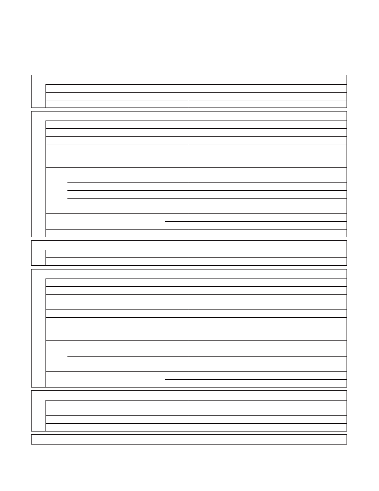
2-2. Major Component Specifications
2-2-1. Outdoor Unit
Outdoor Unit CU-3KS19NBU
Control PCB
Part No.
Controls
Control Circuit Fuse
Compressor
Type
Compressor Model / Nominal Output
Compressor Oil ... Amount
Coil Resistance (Ambient Temp. 68 °F (20 °C))
Safety Device
CT (Peak current cut-off control)
Compressor Discharge Temp. Control
Operation cut-off control in abnormal ambient Temp.
Overload Relay
Operation Temp.
Run Capacitor
Crankcase Heater
Pints (cc)
Ohm
Model
Micro F
VAC
CB-CU-3KS19NBU
Microprocessor
250V 25A
DC Twin Rotary (Hermetic)
5KD240XAB21 / 1,700W
FV50S ... 1.91 (900)
U - V :
0.720
V - W :
W - U :
CS-7L-2515
Open : 239 °F (115 °C), Close : 212 °F (100 °C)
230V 30W
0.708
0.726
Yes
Yes
Yes
-
-
Fan
Type
Q'ty ... Dia. inch (mm)
Fan Motor
Type
Model ... Q'ty
No. of Poles
Rough Measure RPM (Cool)
Nominal Output
Coil Resistance
(Ambient Temp. 68 °F (20 °C))
Safety Device
Type
Over-Current Protection
Run Capacitor
Heat Exchanger Coil
Coil
Rows
Fins per inch
Face Area
Over-Heat Protection
W
Ohm
Micro F
VAC
2
ft
(m2)
Propeller
1 ... D18-1/8 (D460)
DC Motor
SIC-71FW-D490-1 ... 1
8
750
90
-
Internal Controller
Yes
Yes
-
-
Aluminum Plate Fin / Copper Tube
2
18.1
6.40 (0.595)
External Finish Acrylic baked-on enamel finish
DATA SUBJECT TO CHANGE WITHOUT NOTICE.
17

Outdoor Unit CU-4KS24NBU
Control PCB
Part No.
Controls
Control Circuit Fuse
Compressor
Type
Compressor Model / Nominal Output
Compressor Oil ... Amount
Coil Resistance (Ambient Temp. 68 °F (20 °C))
Safety Device
CT (Peak current cut-off control)
Compressor Discharge Temp. Control
Operation cut-off control in abnormal ambient Temp.
Overload Relay
Run Capacitor
Crankcase Heater
Pints (cc)
Ohm
Model
Operation Temp.
Micro F
VAC
CB-CU-4KS24NBU
Microprocessor
250V 25A
DC Twin Rotary (Hermetic)
5KD240XAB21 / 1,700W
FV50S ... 1.91 (900)
U - V :
0.720
V - W :
W - U :
0.708
0.726
Yes
Yes
Yes
CS-7L-2515
Open : 239 °F (115 °C), Close : 212 °F (100 °C)
-
-
230V 30W
Fan
Type
Q'ty ... Dia. inch (mm)
Fan Motor
Type
Model ... Q'ty
No. of Poles
Rough Measure RPM (Cool)
Nominal Output
Coil Resistance
(Ambient Temp. 68 °F (20 °C))
Safety Device
Type
Over-Current Protection
Over-Heat Protection
Run Capacitor
Heat Exchanger Coil
Coil
Rows
Fins per inch
Face Area
W
Ohm
Micro F
VAC
2
ft
(m2)
Propeller
1 ... D18-1/8 (D460)
DC Motor
SIC-71FW-D490-1 ... 1
8
750
90
-
Internal Controller
Yes
Yes
-
-
Aluminum Plate Fin / Copper Tube
2
18.1
6.40 (0.595)
External Finish Acrylic baked-on enamel finish
DATA SUBJECT TO CHANGE WITHOUT NOTICE.
18
Outdoor Unit CU-4KS31NBU
Control PCB
Part No.
Controls
Control Circuit Fuse
Compressor
Type
Compressor Model / Nominal Output
Compressor Oil ... Amount
Coil Resistance (Ambient Temp. 68 °F (20 °C))
Safety Device
CT (Peak current cut-off control)
Compressor Discharge Temp. Control
Operation cut-off control in abnormal ambient Temp.
Overload Relay
Run Capacitor
Crankcase Heater
Pints (cc)
Ohm
Model
Operation Temp.
Micro F
VAC
CB-CU-4KS31NBU
Microprocessor
250V 25A
DC Twin Rotary (Hermetic)
5JD420XAB22 / 3,000W
FV50S ... 2.55 (1,200)
U - V :
0.435
V - W :
W - U :
0.441
0.452
Yes
Yes
Yes
CS-7L-2515
Open : 239 °F (115 °C), Close : 212 °F (100 °C)
-
-
230V 30W
Fan
Type
Q'ty ... Dia. inch (mm)
Fan Motor
Type
Model ... Q'ty
No. of Poles
Rough Measure RPM (Cool)
Nominal Output
Coil Resistance
(Ambient Temp. 68 °F (20 °C))
Safety Device
Type
Over-Current Protection
Over-Heat Protection
Run Capacitor
Heat Exchanger Coil
Coil
Rows
Fins per inch
Face Area
W
Ohm
Micro F
VAC
2
ft
(m2)
Propeller
1 ... D18-1/8 (D460)
DC Motor
SIC-71FW-D490-1 ... 1
8
800
90
-
Internal Controller
Yes
Yes
-
-
Aluminum Plate Fin / Copper Tube
2
18.1
7.75 (0.72)
External Finish Acrylic baked-on enamel finish
DATA SUBJECT TO CHANGE WITHOUT NOTICE.
19
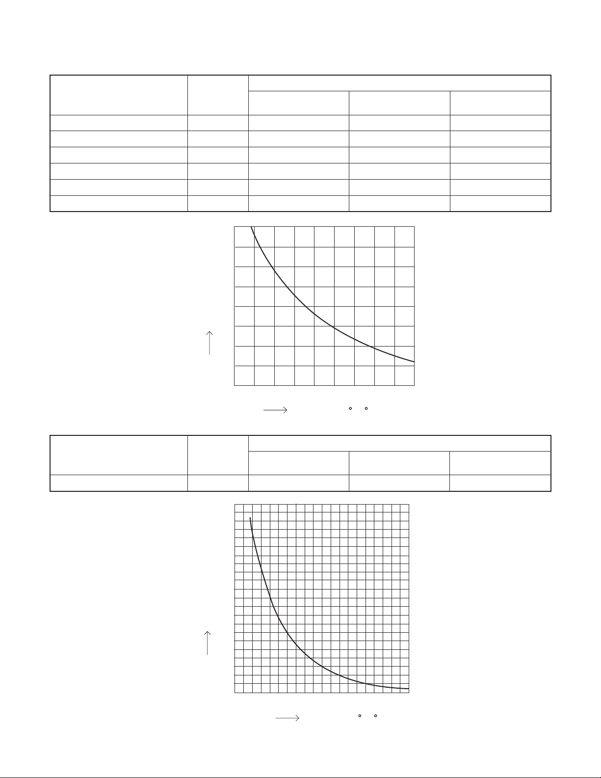
2-3. Other Component Specifications
Sensor Name
Outdoor air temp sensor
Outdoor heat exchanger sensor
AW / AN sensor
BW / BN sensor
CW / CN sensor
DW / DN sensor
Model No.
of sensor
TKS295B
TKS292B
TKS292B
TKS292B
TKS292B
TKS292B
40
35
30
25
20
Resistance (k ohm)
15
10
5
Quantity of Sensor
CU-3KS19NBU CU-4KS24NBU CU-4KS31NBU
1
1
1 / 1
1 / 1
1 / 1
0
1
1
1 / 1
1 / 1
1 / 1
1 / 1
1
1
1 / 1
1 / 1
1 / 1
1 / 1
0
Sensor Name
Compressor temp sensor TKS293B
Model No.
of sensor
200
180
160
140
120
100
Resistance (k ohm)
80
60
40
-
4 5 14 23 32 41 50 59 68
(-20)(-15)(-10) (-5) (0) (5) (10) (15) (20)
Temperature F ( C)
Quantity of Sensor
CU-3KS19NBU CU-4KS24NBU CU-4KS31NBU
11
1
20
0
32 50 68 86 104 122 140 158 176 194
(0) (10) (20) (30) (40) (50) (60)(70) (80) (90)
Temperature F ( C)
20
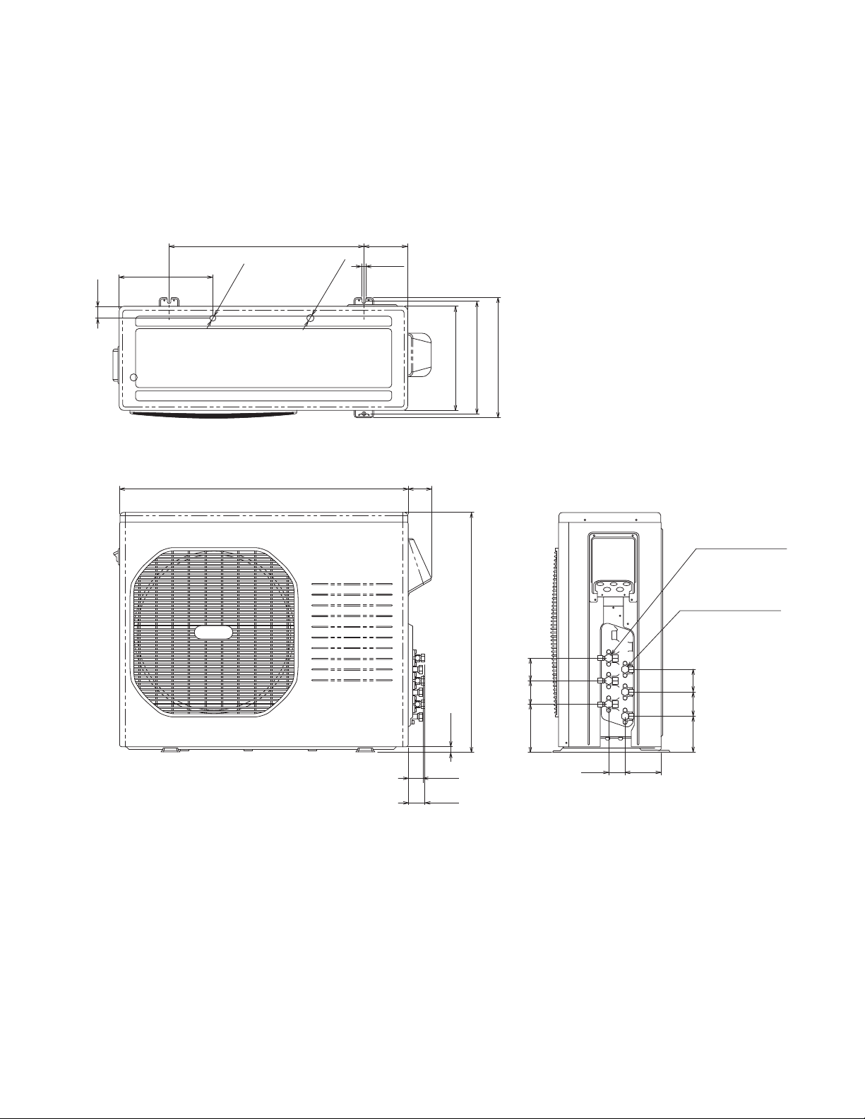
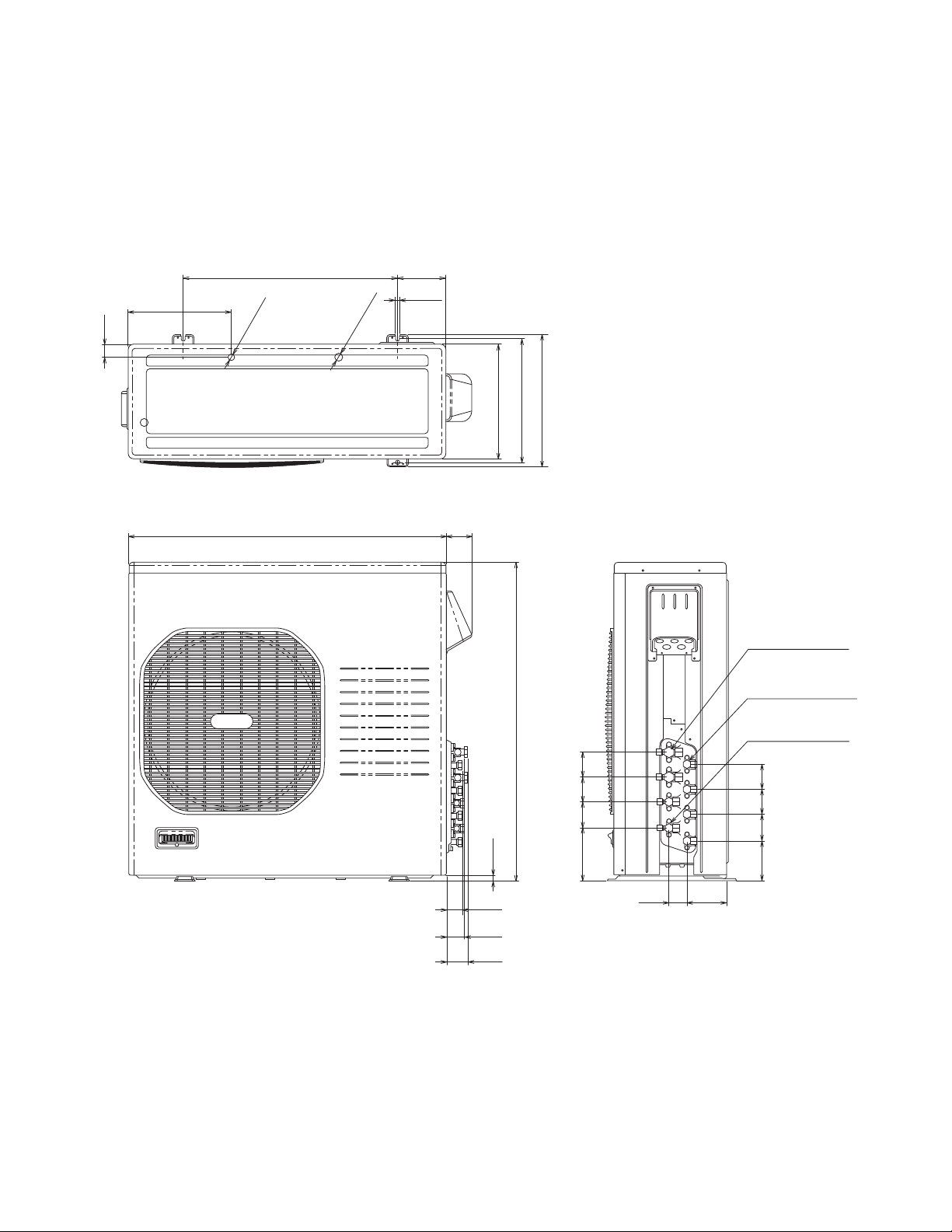
3. DIMENSIONAL DATA
Outdoor Unit CU-3KS19NBU
23-15/16 5-11/32
11-17/32
1-3/8
ID:23/32
2-ID:15/16
15/32
13-19/32
12-19/32(320)
14-17/32
35-7/16(900)
2-15/16
1-13/16
2-1/16
23/32
29-1/8(740)
5-29/32 2-27/32 2-3/4
2-1/32 4-1/2
Wide tube service valve
dia.3/8" (9.52) ×3
Narrow tube service valve
dia.1/4" (6.35) ×3
2-3/4
2-15/16
4-7/16
Unit: inch(mm)
(852-0-0010-11500-0)
21
Outdoor Unit CU-4KS24NBU
23-15/16 5-11/32
11-17/32
1-3/8
ID:23/32
2-ID:15/16
15/32
13-19/32
14-17/32
12-19/32(320)
35-7/16(900)
2-15/16
1-13/16
2-1/16
2-13/32
23/32
29-1/8(740)
2-3/4
5-29/32 2-27/32 2-3/4
2-1/32 4-1/2
Wide tube service valve
dia.1/2" (12.70)
Narrow tube service valve
dia.1/4" (6.35)
Wide tube service valve
dia.3/8" (9.52)
2-3/4 2-3/4
2-15/16
4-7/16
×1
×4
×3
Unit: inch(mm)
(852-0-0010-20500-0)
22
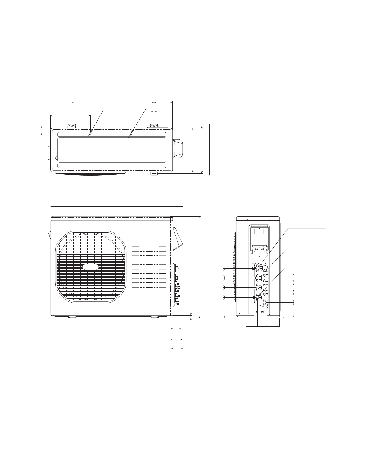
Outdoor Unit CU-4KS31NBU
23-15/16 5-11/32
11-17/32
1-3/8
ID:23/32
2-ID:15/16
15/32
13-19/32
14-17/32
12-19/32(320)
35-7/16(900)
2-15/16
1-13/16
2-1/16
2-13/32
23/32
35-1/32(890)
2-7/8 2-3/4 2-3/4
5-29/32
2-1/32 4-1/2
Wide tube service valve
dia.1/2" (12.70) ×2
Narrow tube service valve
dia.1/4" (6.35) ×4
Wide tube service valve
dia.3/8" (9.52) ×2
2-3/4 2-3/4
2-15/16
4-7/16
Unit: inch(mm)
(852-0-0010-20600-0)
23
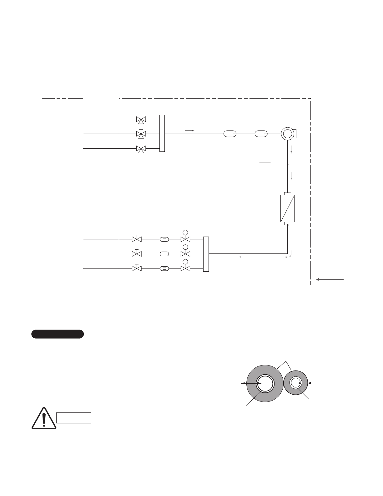
4. REFRIGERANT FLOW DIAGRAM
4-1. Refrigerant Flow Diagram
Outdoor Unit CU-3KS19NBU
Indoor unit Outdoor unit
Service valve on
Wide tube
O.D.3/8"
O.D.3/8"
O.D.3/8"
Narrow tube
O.D.1/4"
O.D.1/4"
O.D.1/4"
wide tube
CW
BW
AW
Header
Service valve on
narrow tube
CN
BN
AN
Strainer Header
Electric
expansion
valve
M
M
M
Sub
accumulator
Main
accumulator
High pressure
switch
H.P.
Compressor
Heat exchanger
Cooling cycle
Insulation of Refrigerant Tubing
IMPORTANT
Because capillary tubing is used in the outdoor unit, both the
wide and narrow tubes of this air conditioner become cold. To
prevent heat loss and wet floors due to dripping of
condensation, both tubes must be well insulated with a
proper insulation material. The thickness of the insulation
should be a min.5/16"(8 mm).
After a tube has been insulated,
CAUTION
never try to bend it into a narrow
curve because it can cause the tube
to break or crack.
24
Thickness:
Min.5/16"(8 mm)
Wide tube
Insulation
Thickness:
Min.5/16"(8 mm)
Narrow tube
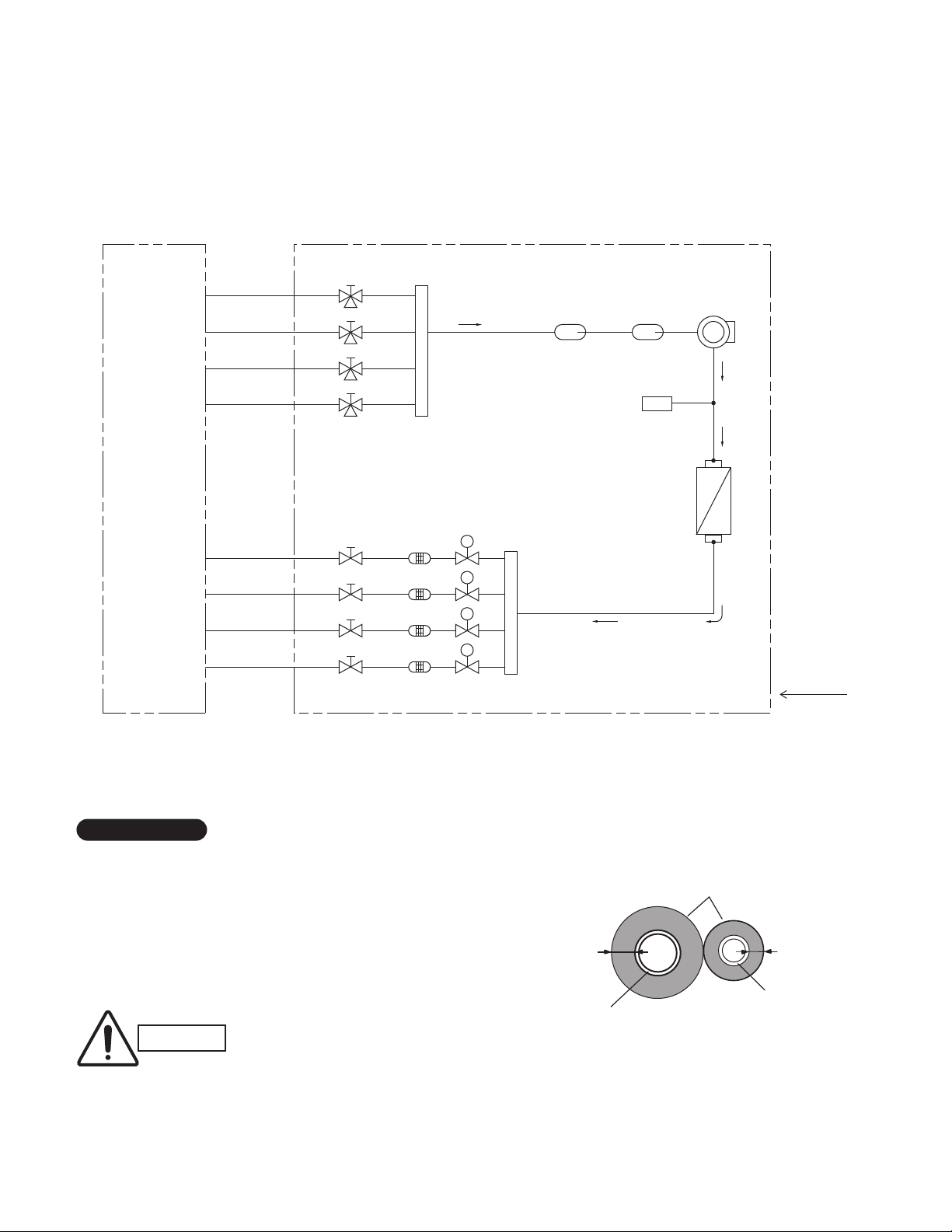
Outdoor Unit CU-4KS24NBU
Indoor unit Outdoor unit
Service valve on
Wide tube
O.D.1/2"
O.D.3/8"
O.D.3/8"
O.D.3/8"
Narrow tube
O.D.1/4"
O.D.1/4"
O.D.1/4"
O.D.1/4"
wide tube
DW
CW
BW
AW
Service valve on
narrow tube
DN
CN
BN
AN
Header
Electric
expansion
valve
M
M
M
M
Strainer Header
Sub
accumulator
Main
accumulator
High pressure
switch
H.P.
Compressor
Heat exchanger
Cooling cycle
Insulation of Refrigerant Tubing
IMPORTANT
Because capillary tubing is used in the outdoor unit, both the
wide and narrow tubes of this air conditioner become cold. To
prevent heat loss and wet floors due to dripping of
condensation, both tubes must be well insulated with a
proper insulation material. The thickness of the insulation
should be a min.5/16"(8 mm).
After a tube has been insulated,
CAUTION
never try to bend it into a narrow
curve because it can cause the tube
to break or crack.
25
Thickness:
Min.5/16"(8 mm)
Wide tube
Insulation
Thickness:
Min.5/16"(8 mm)
Narrow tube
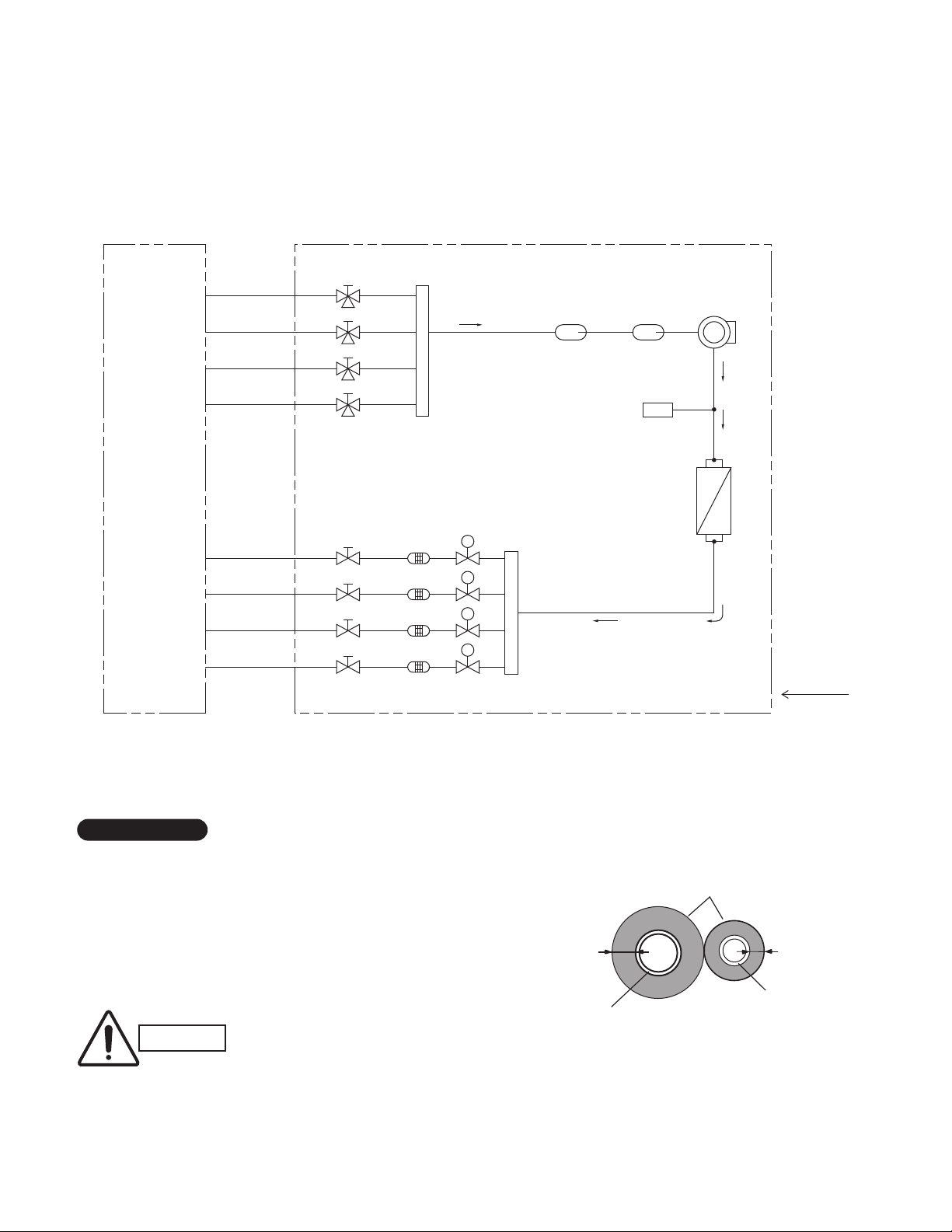
Outdoor Unit CU-4KS31NBU
Indoor unit Outdoor unit
Service valve on
Wide tube
O.D.1/2"
O.D.1/2"
O.D.3/8"
O.D.3/8"
Narrow tube
O.D.1/4"
O.D.1/4"
O.D.1/4"
O.D.1/4"
wide tube
DW
CW
BW
AW
Service valve on
narrow tube
DN
CN
BN
AN
Header
Electric
expansion
valve
M
M
M
M
Strainer Header
Sub
accumulator
Main
accumulator
High pressure
switch
H.P.
Compressor
Heat exchanger
Cooling cycle
Insulation of Refrigerant Tubing
IMPORTANT
Because capillary tubing is used in the outdoor unit, both the
wide and narrow tubes of this air conditioner become cold. To
prevent heat loss and wet floors due to dripping of
condensation, both tubes must be well insulated with a
proper insulation material. The thickness of the insulation
should be a min.5/16"(8 mm).
After a tube has been insulated,
CAUTION
never try to bend it into a narrow
curve because it can cause the tube
to break or crack.
26
Thickness:
Min.5/16"(8 mm)
Wide tube
Insulation
Thickness:
Min.5/16"(8 mm)
Narrow tube
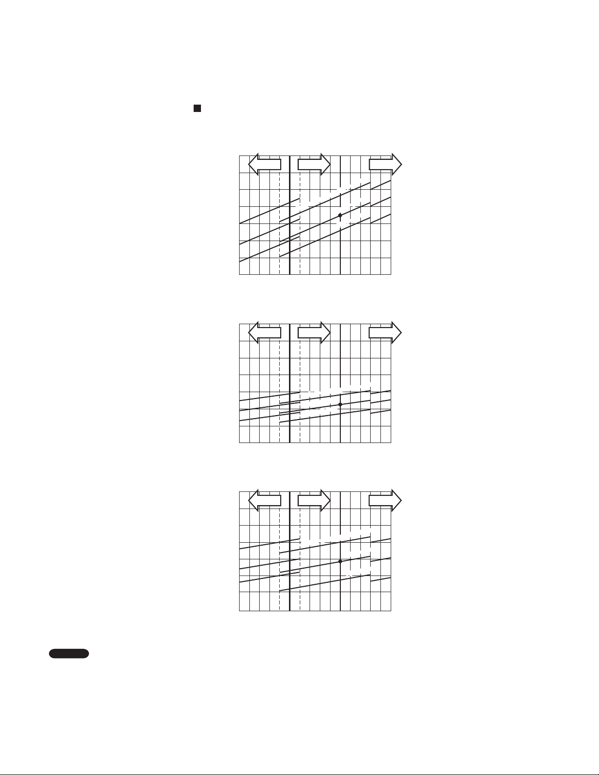
5. PERFORMANCE DATA
5-1. Temperature Charts
5-1-1. Temperature Charts (CU-3KS19NBU)
Outdoor Unit CU-3KS19NBU Indoor Unit CS-MKS7NKU ×1
Cooling Characteristics
(RH : 46%, Indoor fan speed : High fan)
(230V, 60Hz)
(1) Low pressure performance chart
188
(1.3)
psig (MPaG)
174
(1.2)
160
(1.1)
Low pressure at wide tube service valve
146
(1.0)
Lo fan Hi fan HH fan
77
(25)
Indoor air temp. 86°F (30°C)
86
(30)
Outdoor air temperature °F (°C)
80°F (27°C)
75°F (24°C)
95
(35)
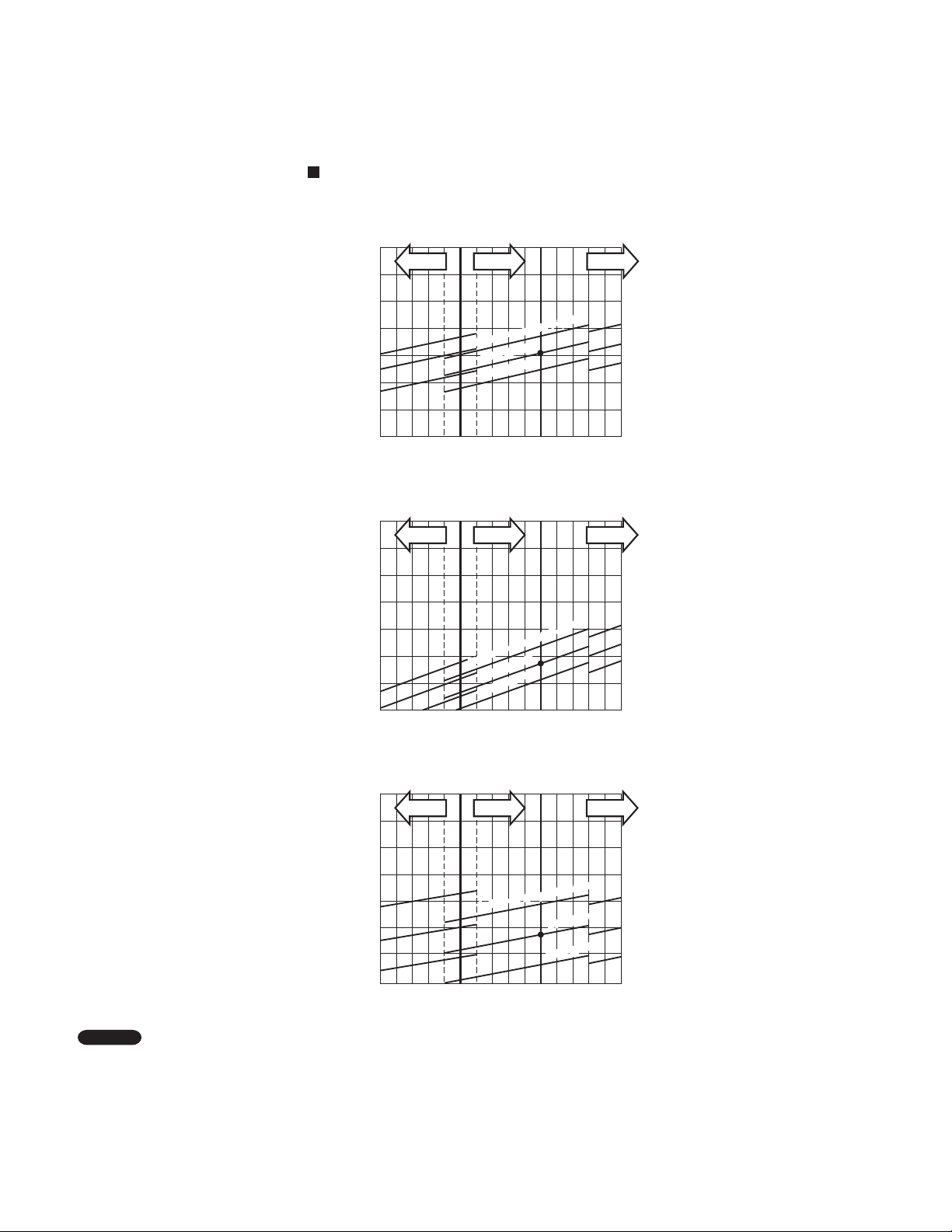
(2) Operating current performance chart
Lo fan Hi fan HH fan
5
4
Indoor air temp. 86°F (30°C)
(30)
86
80°F (27°C)
75°F (24°C)
95
(35)
3
Operating current (A)
2
77
(25)
Outdoor air temperature °F (°C)
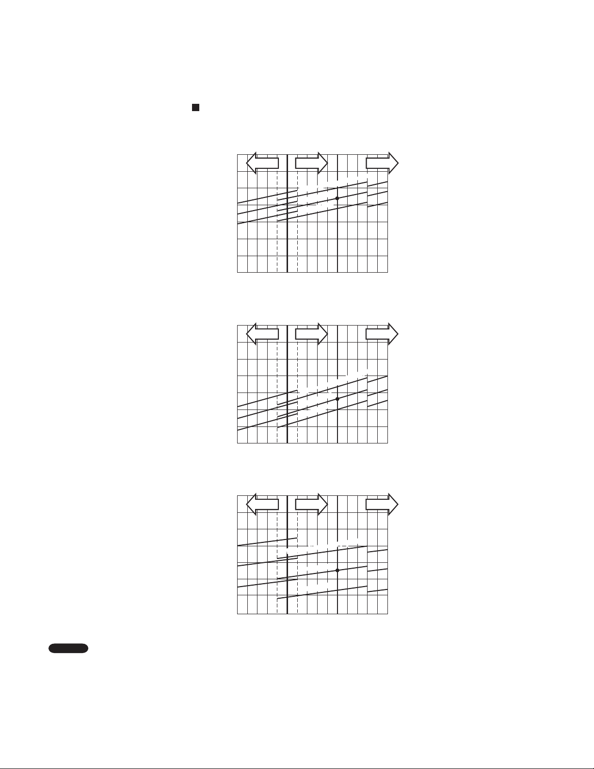
(3) Indoor discharge air performance chart
104
(40)
104
(40)
68.0(20)
64.4(18)
60.8(16)
57.2(14)
53.6(12)
50.0(10)
46.4( 8)
Indoor discharge air temperature °F (°C)
Lo fan Hi fan HH fan
Indoor air temp. 86°F (30°C)
77
(25)
86
(30)
Outdoor air temperature °F (°C)
95
(35)
80°F (27°C)
75°F (24°C)
104
(40)
NOTE
• This performance chart shows operation of a single wall-mounted indoor unit. The performance chart will vary depending on
the indoor unit type.
• Check each performance value in test-run mode. Electrical performance values represent a combined indoor/outdoor value.
(In this case, be sure to stop all the indoor units where performance is not being checked.)
• The performance is for a tubing length of 24.6t (7.5m). If the tubing length is different, the performance chart will vary.
27
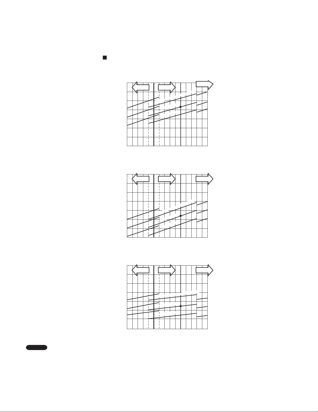
Outdoor Unit CU-3KS19NBU Indoor Unit CS-MKS9NKU ×1
Cooling Characteristics
(RH : 46%, Indoor fan speed : High fan)
(230V, 60Hz)
(1) Low pressure performance chart
188
(1.3)
psig (MPaG)
174
(1.2)
160
(1.1)
Low pressure at wide tube service valve
146
(1.0)
Lo fan Hi fan
77
(25)
Indoor air temp. 86°F (30°C)
80°F (27°C)
75°F (24°C)
86
(30)
Outdoor air temperature °F (°C)
95
(35)
(2) Operating current performance chart
Lo fan Hi fan
6
5
4
Operating current (A)
3
77
(25)
Indoor air temp. 86°F (30°C)
80°F (27°C)
75°F (24°C)
86
(30)
Outdoor air temperature °F (°C)
95
(35)
HH fan
HH fan
104
(40)
104
(40)
(3) Indoor discharge air performance chart
68.0(20)
64.4(18)
60.8(16)
57.2(14)
53.6(12)
50.0(10)
46.4( 8)
Indoor discharge air temperature °F (°C)
Lo fan Hi fan
77
(25)
Indoor air temp. 86°F (30°C)
86
(30)
Outdoor air temperature °F (°C)
95
(35)
NOTE
• This performance chart shows operation of a single wall-mounted indoor unit. The performance chart will vary depending on
the indoor unit type.
• Check each performance value in test-run mode. Electrical performance values represent a combined indoor/outdoor value.
(In this case, be sure to stop all the indoor units where performance is not being checked.)
• The performance is for a tubing length of 24.6ft (7.5m). If the tubing length is different, the performance chart will vary.
80°F (27°C)
75°F (24°C)
HH fan
104
(40)
28
Outdoor Unit CU-3KS19NBU Indoor Unit CS-MKS12NKU ×1
Cooling Characteristics
(RH : 46%, Indoor fan speed : High fan)
(230V, 60Hz)
(1) Low pressure performance chart
174
(1.2)
psig (MPaG)
160
(1.1)
146
(1.0)
Low pressure at wide tube service valve
132
(0.9)
Lo fan Hi fan
77
(25)
Indoor air temp. 86°F (30°C)
80°F (27°C)
75°F (24°C)
86
(30)
Outdoor air temperature °F (°C)
95
(35)
(2) Operating current performance chart
Lo fan Hi fan
6
5
Indoor air temp. 86°F (30°C)
(30)
86
80°F (27°C)
75°F (24°C)
95
(35)
4
Operating current (A)
3
77
(25)
Outdoor air temperature °F (°C)
HH fan
HH fan
104
(40)
104
(40)
(3) Indoor discharge air performance chart
68.0(20)
64.4(18)
60.8(16)
57.2(14)
53.6(12)
50.0(10)
46.4( 8)
Indoor discharge air temperature °F (°C)
Lo fan Hi fan
77
(25)
Indoor air temp. 86°F (30°C)
80°F (27°C)
75°F (24°C)
86
(30)
Outdoor air temperature °F (°C)
95
(35)
NOTE
• This performance chart shows operation of a single wall-mounted indoor unit. The performance chart will vary depending on
the indoor unit type.
• Check each performance value in test-run mode. Electrical performance values represent a combined indoor/outdoor value.
(In this case, be sure to stop all the indoor units where performance is not being checked.)
• The performance is for a tubing length of 24.6ft (7.5m). If the tubing length is different, the performance chart will vary.
HH fan
104
(40)
29
Outdoor Unit CU-3KS19NBU Indoor Unit CS-MKS18NKU ×1
Cooling Characteristics
(RH : 46%, Indoor fan speed : High fan)
(230V, 60Hz)
(1) Low pressure performance chart
174
(1.2)
psig (MPaG)
160
(1.1)
146
(1.0)
Low pressure at wide tube service valve
132
(0.9)
Lo fan Hi fan
77
(25)
Indoor air temp. 86°F (30°C)
80°F (27°C)
75°F (24°C)
86
(30)
Outdoor air temperature °F (°C)
(2) Operating current performance chart
8
Lo fan Hi fan
7
95
(35)
HH fan
HH fan
104
(40)
6
Operating current (A)
5
77
(25)
Indoor air temp. 86°F (30°C)
80°F (27°C)
75°F (24°C)
86
(30)
Outdoor air temperature °F (°C)
95
(35)
104
(40)
(3) Indoor discharge air performance chart
68.0(20)
64.4(18)
60.8(16)
57.2(14)
53.6(12)
50.0(10)
Indoor discharge air temperature °F (°C)
46.4( 8)
Lo fan Hi fan
77
(25)
Indoor air temp. 86°F (30°C)
80°F (27°C)
75°F (24°C)
86
(30)
Outdoor air temperature °F (°C)
95
(35)
NOTE
• This performance chart shows operation of a single wall-mounted indoor unit. The performance chart will vary depending on
the indoor unit type.
• Check each performance value in test-run mode. Electrical performance values represent a combined indoor/outdoor value.
(In this case, be sure to stop all the indoor units where performance is not being checked.)
• The performance is for a tubing length of 24.6ft (7.5m). If the tubing length is different, the performance chart will vary.
HH fan
104
(40)
30
 Loading...