

Panasonic CU-4KE31NBU, CU-3KE19NBU, CU-4KE24NBU Installation Manual

APPENDIX A
INSTALLATION INSTRUCTIONS
CU-3KE19NBU
CU-4KE24NBU
CU-4KE31NBU
(852-6-4190-584-00-2)
A-1
For Outdoor Unit
INSTALLATION INSTRUCTIONS
Split System Air Conditioner
This air conditioner uses the refrigerant R410A.
NOTE
External diameter of service port R410A: 5/16"
Contents
Page
IMPORTANT!
Please Read Before Starting .................................. 2
Model Combinations
Combine indoor and outdoor units only as listed
below.
Model No.
Indoor Unit Outdoor Unit
CS-MKE7NKU CU-3KE19NBU
CS-MKE9NKU CU-4KE24NBU
CS-MKE12NKU CU-4KE31NBU
CS-MKE18NKU
CS-MKE24NKU
CS-MKE9NB4U
CS-MKE12NB4U
CS-KE18NB4UW
Power Source:
60 Hz, single-phase, 230 / 208 VAC
1. GENERAL .......................................................... 4
1-1. Tools Required for Installation (not supplied)
1-2. Accessories Supplied with Unit
1-3. Optional Copper Tubing Kit
1-4. Type of Copper Tube and Insulation Material
1-5. Additional Materials Required for Installation
2. INSTALLATION SITE SELECTION ................... 5
2-1. Indoor Unit
2-2. Connecting Indoor Units
2-3. Outdoor Unit
2-4. Baffle Plate for the Outdoor Unit
2-5. Outer Dimensions of Outdoor Unit
2-6. Diagram of Outdoor Unit Installation
3. INSTALLATION PROCESS .............................. 16
3-1. Embedding the Tubing and Wiring
3-2. Use of the Flaring Method
3-3. Flaring Procedure with a Flare Tool
3-4. Caution before Connecting Tubes Tightly
3-5. Tubing Connections
3-6. Insulation of Refrigerant Tubing
3-7. Taping the Tubes
3-8. Finishing the Installation
Combination example
Indoor unit B
Indoor unit A
Outdoor unit
Indoor unit D
Indoor unit C
4. AIR PURGING................................................... 19
Air Purging with a Vacuum Pump (for Test Run)
Pump Down
5. WIRING INSTRUCTIONS ................................ 22
5-1. General Precautions on Wiring
5-2. Recommended Wire Length and Diameter
5-3. Wiring System Diagram
5-4. How to Connect Wiring to the Terminal
5-5. Wiring Instructions for the Outdoor Unit
6. TEST RUN......................................................... 26
7. CONNECTING A HOME AUTOMATION
DEVICE ............................................................. 27
8. INSTALLATION CHECK SHEET ...................... 27
85264190584002 2011 CV6233187853
IMPORTANT!
Please Read Before Starting
This air conditioning system meets strict safety and operating
standards. As the installer or service person, it is an important
part of your job to install or service the system so it operates
safely and efficiently.
When Transporting
Be careful when picking up and moving the indoor and outdoor units. Get a partner to help, and bend your knees when
lifting to reduce strain on your back. Sharp edges or thin aluminum fins on the air conditioner can cut your fingers.
When Installing…
For safe installation and trouble-free operation, you
must:
Carefully read this instruction booklet before beginning.
Follow each installation or repair step exactly as shown.
Observe all local, state, and national electrical codes.
Pay close attention to all warning and caution notices
given in this manual.
This symbol refers to a hazard
WARNING
CAUTION
or unsafe practice which can
result in severe personal injury
or death.
This symbol refers to a hazard
or unsafe practice which can
result in personal injury or product or property damage.
If Necessary, Get Help
These instructions are all you need for most installation
sites and maintenance conditions. If you require help for a
special problem, contact our sales/service outlet or your
certified dealer for additional instructions.
In Case of Improper Installation
The manufacturer shall in no way be responsible for improper installation or maintenance service, including failure to
follow the instructions in this document.
SPECIAL PRECAUTIONS
Select an installation location which is rigid and strong
enough to support or hold the unit, and select a location for
easy maintenance.
…In a Ceiling or Wall
Make sure the ceiling/wall is strong enough to hold the
unit’s weight. It may be necessary to construct a strong
wood or metal frame to provide added support.
…In a Room
Properly insulate any tubing run inside a room to prevent
“sweating” that can cause dripping and water damage to
walls and floors.
Keep the fire alarm and the air
CAUTION
…In Moist or Uneven Locations
Use a raised concrete pad or concrete blocks to provide a
solid, level foundation for the outdoor unit. This prevents
water damage and abnormal vibration.
…In an Area with High Winds
Securely anchor the outdoor unit down with bolts and a
metal frame. Provide a suitable air baffle.
…In a Snowy Area
Install the outdoor unit on a raised platform that is higher
than drifting snow. Provide snow vents.
outlet at least 1.5 m away from
the unit.
WARNING
'RQRWVXSSO\SRZHUWRWKHXQLWXQWLODOOZLULQJDQGWXELQJ
are completed or reconnected and checked.
+LJKO\GDQJHURXVHOHFWULFDOYROWDJHVDUHXVHGLQWKLV
system. Carefully refer to the wiring diagram and these
instructions when wiring. Improper connections and
inadequate grounding can cause accidental injury or
death.
*URXQGWKHXQLW following local electrical codes.
&RQQHFWDOOZLULQJWLJKWO\/RRVHZLULQJPD\FDXVHRYHU
heating at connection points and a possible fire hazard.
7RSUHYHQWSRVVLEOHKD]DUGVIURPLQVXODWLRQIDLOXUH
the unit must be grounded.
When Wiring
ELECTRICAL SHOCK CAN CAUSE SEVERE
PERSONAL INJURY OR DEATH. ONLY A
QUALIFIED, EXPERIENCED ELECTRICIAN
SHOULD ATTEMPT TO WIRE THIS SYSTEM.
When Connecting Refrigerant Tubing
:KHQSHUIRUPLQJpiping work
do not mix air except for specified refrigerant (R410A) in
refrigeration cycle. It causes
capacity down, and risk of
explosion and injury due to
high tension inside the refrige-
WARNING
9HQWLODWHWKHURRPZHOOLQWKHHYHQWWKDWUHIULJHUDQW
gas leaks during the installation. Be careful not to allow
contact of the refrigerant gas with a flame as this will
cause the generation of poisonous gas.
2
rant cycle.
5HIULJHUDQWJDVOHDNDJHPD\
cause fire.
'RQRWDGGRUUHSODFHUHIULJHUDQW
other than specified type.
It may cause product damage,
burst and injury etc.
8VHWKHIODUHPHWKRGIRUFRQQHFWLQJWXELQJ
$SSO\UHIULJHUDQWOXEULFDQWWRWKHPDWFKLQJVXUIDFHVRI
the flare and union tubes before connecting them, then
tighten the nut with a torque wrench for a leak-free
connection.
&KHFNFDUHIXOO\IRUOHDNVEHIRUHVWDUWLQJWKHWHVWUXQ
'RQRWOHDNUHIULJHUDQWZKLOHSLSLQJZRUNIRUDQLQVWDOODWLRQ
or re-installation, and while repairing refrigeration parts.
Handle liquid refrigerant carefully as it may cause frostbite.
When Servicing
7XUQWKHSRZHU2)) DWWKHPDLQSRZHUER[PDLQV
before opening the unit to check or repair electrical
parts and wiring.
.HHS\RXUILQJHUVDQGFORWKLQJDZD\IURPDQ\PRYLQJ
parts.
&OHDQXSWKHVLWHDIWHU\RXILQLVKUHPHPEHULQJWRFKHFN
that no metal scraps or bits of wiring have been left inside
the unit being serviced.
Others
CAUTION
9HQWLODWHDQ\HQFORVHGDUHDVZKHQLQVWDOOLQJRUWHVWLQJ
the refrigeration system. Escaped refrigerant gas, on
contact with fire or heat, can produce dangerously
toxic gas.
&RQILUPXSRQFRPSOHWLQJLQVWDOODWLRQWKDWQRUHIULJHUDQW
gas is leaking. If escaped gas comes in contact with a
stove, gas water heater, electric room heater or other heat
source, it can produce dangerously toxic gas.
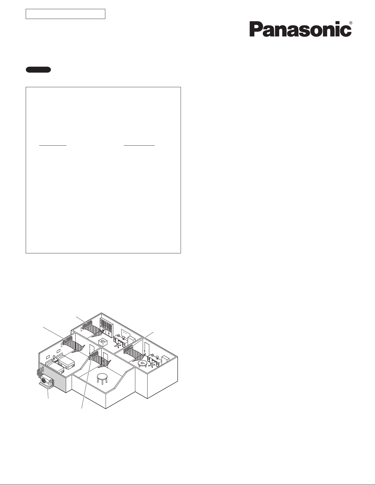
'RQRWLQVWDOORQO\DVLQJOHLQGRRUXQLW
'RQRWWRXFKWKHDLULQOHWRUWKHVKDUSDOXPLQXP
fins of the outdoor unit. You may get injured.
'RQRWVLWRUVWHSRQWKHXQLW\RXPD\IDOOGRZQ
accidentally.
'RQRWVWLFNDQ\REMHFWLQWRWKH)$1&$6(
You may be injured and the unit may be damaged.
NOTE
The illustrations are based on the typical appearance of
a standard model. Consequently, the shape may differ
from that of the air conditioner that you are installing.
3
1. General
This booklet briefly outlines where and how to install the air conditioning system. Please read over the entire set of instructions for the indoor and outdoor units and make sure all accessory parts listed are with the system before beginning.
If the electric wiring diagram does not appear in this manual, please check for the diagram on the indoor unit.
1-1. Tools Required for Installation (not supplied)
1. Standard screwdriver
2. Phillips head screwdriver
3. Knife or wire stripper
4. Tape measure
5. Carpenter’s level
6. Sabre saw or key hole saw
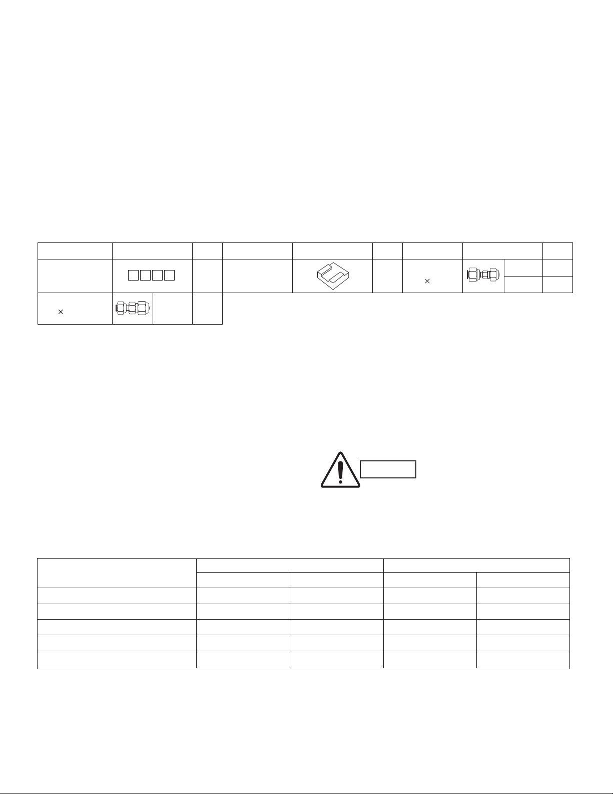
1-2. Accessories Supplied with Unit
Table 1
Parts Figure Q’ty Parts Figure Q’ty Parts Figure Q’ty
Labels for inter-unit
cable and tube
Reducer
(3/8" 1/2")
A B C D
CU-3KE19NBU
7. Hacksaw
8. Core bits
9. Hammer
10. Drill
11. Tube cutter
12. Tube flaring tool
4 each
Cushion rubber 4
1
13. Torque wrench
14. Adjustable wrench
15. Reamer (for deburring)
16. Vacuum pump (For R410A)
17. Manifold valve
Reducer
(1/2" 3/8")
CU-4KE24NBU
CU-4KE31NBU
Packed in the outdoor unit.
1
2
1-3. Optional Copper Tubing Kit
Copper tubing for connecting the outdoor unit to the
indoor unit is available in kits which contain the narrow
and wide tubing, fittings and insulation. Consult your
nearest sales outlet or air conditioning workshop.
1-4. Type of Copper Tube and Insulation Material
If you wish to purchase these materials separately from
a local source, you will need:
1. Deoxidized annealed copper tube for refrigerant tubing as detailed in Table 2.
Cut each tube to the appropriate lengths 1' to 1'4"
(30 cm to 40 cm) to dampen vibration between units.
Table 2
Model
CS-MKE7NKU, CS-MKE9NKU, CS-MKE12NKU
CS-MKE18NKU
CS-MKE24NKU
CS-MKE9NB4U, CS-MKE12NB4U
CS-KE18NB4UW
Outer Dia. Thickness Outer Dia. Thickness
1/4" (6.35 mm) 0.0314" (0.8 mm) 3/8" (9.52 mm) 0.0314" (0.8 mm)
1/4" (6.35 mm) 0.0314" (0.8 mm) 1/2" (12.70 mm) 0.0314" (0.8 mm)
1/4" (6.35 mm) 0.0314" (0.8 mm) 5/8" (15.88 mm) 0.0393" (1.0 mm)
1/4" (6.35 mm) 0.0314" (0.8 mm) 3/8" (9.52 mm) 0.0314" (0.8 mm)
1/4" (6.35 mm) 0.0314" (0.8 mm) 1/2" (12.70 mm) 0.0314" (0.8 mm)
Narrow Tube Wide Tube
2. Foamed polyethylene insulation for the specified
copper tubes as required to precise length of tubing.
Wall thickness of the insulation should be not less
than 5/16" (8 mm).
3. Use insulated copper wire for field wiring. Wire size
varies with the total length of wiring.
Refer to 5. Wiring Instructions for details.
CAUTION
Check local electrical codes
and regulations before
obtaining wire. Also, check
any specified instructions or
limitations.
1-5. Additional Materials Required for Installation
1. Refrigeration (armored) tape
2. Insulated staples or clamps for connecting wire
(See local codes.)
3. Putty
4. Refrigeration lubricant
5. Clamps or saddles to secure refrigerant tubing
4
2. Installation Site Selection
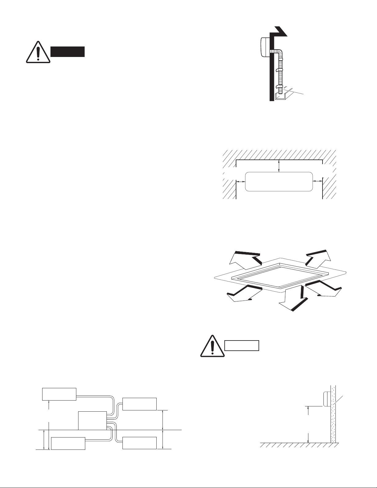
2-1. Indoor Unit
To prevent abnormal heat generation
WARNING
AVOID:
direct sunlight.
nearby heat sources that may affect performance of the
unit.
areas where leakage of flammable gas may be expected.
and the possibility of fire, do not
place obstacles, enclosures and
grilles in front of or surrounding the
air conditioner in a way that may
block air flow.
Indoor unit
Drain hose
Outside drainage
Fig. 1
For wall-mounted units
placing or allowing any obstructions near the air conditioner
inlet or outlet.
installing in rooms that contain instant-on (rapid-start)
fluorescent lamps. (These may prevent the air conditioner
from receiving signals.)
places where large amounts of oil mist exist.
installing in locations where there are devices that
generate high-frequency emissions.
DO:
select an appropriate position from which every corner of
the room can be uniformly air-conditioned. (High on a wall
is best for wall-mounted types.)
select a location that will hold the weight of the unit.
select a location where tubing and drain hose have the
shortest run to the outside. (Fig. 1)
allow room for operation and maintenance as well as
unrestricted air flow around the unit. (Fig. 2a or 2b)
install the unit within the maximum elevation difference
(H1, H2, H3, H4) above or below the outdoor unit and
within a total tubing length (L1+L2+L3, L1+L2+L3+L4)
from the outdoor unit as detailed in Table 3 and Fig. 3a.
INDOOR
UNIT (1)
Elevation
difference (H1)
H4
INDOOR
UNIT (4)
Tubing length (L1)
OUTDOOR
UNIT
L4
L2
L3
INDOOR
UNIT (2)
INDOOR
UNIT (3)
H2
H3
2" (5 cm)
min.
Front View
Fig. 2a
For ceiling-mounted cassette units
3.3 ft.
(1m)
3.3 ft.
(1m)
Fig. 2b
CAUTION
$LUGHOLYHU\IURPDFHLOLQJ
mounted cassette unit will
be degraded if the distance
from the floor to the ceiling
is greater than 10 ft. (3 m).
)RUVWDEOHRSHUDWLRQRIWKH
air conditioner, do not install
wall-mounted units less
than 5' (1.5 m) from floor
level. (Fig. 3b)
6" (15 cm)
min.
(1m)
3.3 ft.
(1m)
Indoor unit
Minimum height
from floor level
5' (1.5 m)
Floor level
2" (5 cm)
min.
3.3 ft.
3.3 ft.
(1m)
Wall
Fig. 3a
Fig. 3b
5
install the indoor unit more than 3.3' (1 m) away from any
antenna or power lines or connecting wires used for television, radio, telephone, security system, or intercom.
Electrical noise from any of these sources may affect
operation.
install in a sturdy manner to avoid increased operating
noise.
Table 3
Max. Max. Allowable Total Limit of Limit of Elevation Required Amount
Allowable Tubing Length Total Tubing Length Difference of Additional
Model Tubing Length at Shipment (L1+L2+L3) or (H1, H2, H3, H4) Refrigerant
Per Unit (L1+L2+L3) or (L1+L2+L3+L4) (ft.) (oz./ft.)*
(ft.) (L1+L2+L3+L4) (ft.)
(ft.)
CU-3KE19NBU 82 150 (L1+L2+L3) 150 (L1+L2+L3) 50 —
CU-4KE24NBU 82 150 (L1+L2+L3+L4) 200 (L1+L2+L3+L4) 50 0.22
CU-4KE31NBU 100 150 (L1+L2+L3+L4) 230 (L1+L2+L3+L4) 50 0.22
* If total tubing length becomes 150 to 200 ft. (Max.) or 150 to 230 ft. (Max.), charge additional refrigerant (R410A) by 0.22 oz./ft.
No additional charge of compressor oil is necessary. For more detailed charging information, refer to the Technical & Service Manual.
6
2-2. Connecting Indoor Units
Figures (4a) – (4k) show the different types of indoor unit connections, including the use of a reducer.
To select the required indoor unit to be connected, refer to the Combination Table that was included in the
outdoor unit package.
(1) Connecting indoor unit for CU-3KE19NBU
(A)
3/8"(9.52mm)
3/8"(9.52
3/8"(9.52
mm
mm
Outdoor unit Indoor unit
C
1/4"(6.35
B
)
A
)
1/4"(6.35
1/4"(6.35
mm
mm
mm
)
)
)
3/8"(9.52
3/8"(9.52
3/8"(9.52
mm
mm
mm
)
(CS-MKE7NKU,CS-MKE9NKU,CS-MKE12NKU)
(CS-MKE9NB4U,CS-MKE12NB4U)
)
(CS-MKE7NKU,CS-MKE9NKU,CS-MKE12NKU)
(CS-MKE9NB4U,CS-MKE12NB4U)
)
(CS-MKE7NKU,CS-MKE9NKU,CS-MKE12NKU)
(CS-MKE9NB4U,CS-MKE12NB4U)
Fig. 4a
(B)
3/8"(9.52mm)
3/8"(9.52
3/8"(9.52
mm
mm
Flare 3/8"(9.52
A joint for connecting tubes of
different sizes
(3/8"(9.52mm) 1/2"(12.70mm)) Supplied Reducer
Outdoor unit Indoor unit
C
1/4"(6.35mm)
B
)
A
)
Union 1/2"(12.70mm)
mm
)
1/4"(6.35
1/4"(6.35
mm
mm
)
)
3/8"(9.52
3/8"(9.52
1/2"(12.70
mm
mm
mm
)
(CS-MKE7NKU,CS-MKE9NKU,CS-MKE12NKU)
(CS-MKE9NB4U,CS-MKE12NB4U)
)
(CS-MKE7NKU,CS-MKE9NKU,CS-MKE12NKU)
(CS-MKE9NB4U,CS-MKE12NB4U)
)
(CS-MKE18NKU)
(CS-KE18NB4UW)
(2) Connecting indoor unit for CU-4KE24NBU
(A)
(1/2"(12.70
Outdoor unit Indoor unit
D
1/2"(12.70mm)
3/8"(9.52
3/8"(9.52
3/8"(9.52
mm
mm
mm
1/4"(6.35
C
)
B
)
A
)
1/4"(6.35
1/4"(6.35
1/4"(6.35
mm
mm
mm
mm
Fig. 4b
mm
) 3/8"(9.52mm)) Supplied Reducer
Union 3/8"(9.52mm)Flare 1/2"(12.70mm)
mm
)
)
)
)
3/8"(9.52
3/8"(9.52
3/8"(9.52
3/8"(9.52
mm
mm
mm
)
)
)
)
Fig. 4c
(CS-MKE7NKU,CS-MKE9NKU,CS-MKE12NKU)
(CS-MKE9NB4U,CS-MKE12NB4U)
(CS-MKE7NKU,CS-MKE9NKU,CS-MKE12NKU)
(CS-MKE9NB4U,CS-MKE12NB4U)
(CS-MKE7NKU,CS-MKE9NKU,CS-MKE12NKU)
(CS-MKE9NB4U,CS-MKE12NB4U)
(CS-MKE7NKU,CS-MKE9NKU,CS-MKE12NKU)
(CS-MKE9NB4U,CS-MKE12NB4U)
7
(B)
1/2"(12.70
3/8"(9.52
3/8"(9.52
3/8"(9.52
mm
mm
mm
mm
(C)
1/2"(12.70mm)
3/8"(9.52mm)
3/8"(9.52
3/8"(9.52
mm
mm
Outdoor unit Indoor unit
D
)
C
)
B
)
A
)
1/4"(6.35
1/4"(6.35
1/4"(6.35
1/4"(6.35
mm
mm
mm
mm
)
)
)
)
1/2"(12.70
3/8"(9.52
3/8"(9.52
3/8"(9.52
mm
mm
mm
mm
)
)
)
)
Fig. 4d
(1/2"(12.70mm) 5/8"(15.88mm)) Locally purchased
Union 5/8"(15.88mm)Flare 1/2"(12.70mm)
Outdoor unit Indoor unit
D
1/4"(6.35
C
1/4"(6.35
B
)
A
)
1/4"(6.35
1/4"(6.35
mm
mm
mm
mm
5/8"(15.88mm)
)
3/8"(9.52
)
3/8"(9.52
)
3/8"(9.52
)
mm
mm
mm
)
)
)
(CS-MKE18NKU)
(CS-KE18NB4UW)
(CS-MKE7NKU,CS-MKE9NKU,CS-MKE12NKU)
(CS-MKE9NB4U,CS-MKE12NB4U)
(CS-MKE7NKU,CS-MKE9NKU,CS-MKE12NKU)
(CS-MKE9NB4U,CS-MKE12NB4U)
(CS-MKE7NKU,CS-MKE9NKU,CS-MKE12NKU)
(CS-MKE9NB4U,CS-MKE12NB4U)
(CS-MKE24NKU)
(CS-MKE7NKU,CS-MKE9NKU,CS-MKE12NKU)
(CS-MKE9NB4U,CS-MKE12NB4U)
(CS-MKE7NKU,CS-MKE9NKU,CS-MKE12NKU)
(CS-MKE9NB4U,CS-MKE12NB4U)
(CS-MKE7NKU,CS-MKE9NKU,CS-MKE12NKU)
(CS-MKE9NB4U,CS-MKE12NB4U)
(D)
1/2"(12.70
3/8"(9.52
3/8"(9.52
3/8"(9.52
Fig. 4e
(3/8"(9.52
Locally purchased
Outdoor unit Indoor unit
D
mm
)
C
mm
mm
mm
)
B
)
A
)
1/4"(6.35
1/4"(6.35
1/4"(6.35
1/4"(6.35
mm
)
mm
)
mm
)
mm
) 1/2"(12.70mm))
Union 1/2"(12.70
1/2"(12.70
mm
)
1/2"(12.70mm)
3/8"(9.52
3/8"(9.52
mm
mm
mm
mm
)
)
)Flare 3/8"(9.52mm)
)
Fig. 4f
(CS-MKE18NKU)
(CS-KE18NB4UW)
(CS-MKE18NKU)
(CS-KE18NB4UW)
(CS-MKE7NKU,CS-MKE9NKU,CS-MKE12NKU)
(CS-MKE9NB4U,CS-MKE12NB4U)
(CS-MKE7NKU,CS-MKE9NKU,CS-MKE12NKU)
(CS-MKE9NB4U,CS-MKE12NB4U)
8
 Loading...