

Panasonic AW-RP505 User Manual

Multi Hybrid Control Panel
AW-RP505
Before attempting to connect or operate this product,
please read these instructions completely.
Warning:
Do not install this product near any object that burns easily.
In case of using a halogen lamp, installation of it near such
an object could cause a fire due to the heat generated by the
lamp.
This digital apparatus does not exceed the Class A limits for
radio noise emissions from digital apparatus set out in the
Radio Interference Regulations of the Canadian Department
of Communications.
WARNING:
TO PREVENT FIRE OR ELECTRIC SHOCK HAZARD, DO NOT EXPOSE THIS APPLIANCE TO RAIN OR MOIS
TURE.
The lightning flash with arrowhead symbol, within an equilateral triangle, is
intended to alert the user to the presence of uninsulated "dangerous voltage"
within the product's enclosure that may
be of sufficient magnitude to constitute a
risk of electric shock to persons.
The exclamation point within an equilateral triangle is intended to alert the user
to the presence of important operating
and maintenance (servicing) instructions
in the literature accompanying the appliance.
The serial number of this product may be found on the bottom of the unit.
You should note the serial number of this unit in the space
provided and retain this book as a permanent record of your
purchase to aid identification in the event of theft.
Model No.
Serial No.
CAUTION:
TO REDUCE THE RISK OF ELECTRIC SHOCK, DO
NOT REMOVE COVER (OR BACK). NO USER SERVICEABLE PARTS INSIDE.
REFER SERVICING TO QUALIFIED SERVICE PERSONNEL.
CAUTION
RISK OF ELECTRIC SHOCK
DO NOT OPEN
SA 1965
SA 1966
For U.S.A
For CANADA

-1-
CONTENTS
FEATURES .......................................................................................................................................................................................... 2
PRECAUTIONS ................................................................................................................................................................................... 3
MAJOR OPERATING CONTROLS AND THEIR FUNCTIONS ............................................................................................................ 4
INSTALLATION OF PAN/TILT HEAD ................................................................................................................................................. 19
CONNECTIONS .................................................................................................................................................................................. 22
OPERATING PROCEDURES .............................................................................................................................................................. 26
RACK MOUNTING ............................................................................................................................................................................. 34
SPECIFICATIONS ............................................................................................................................................................................... 36
ACCESSORIES ................................................................................................................................................................................... 37

-2-
FEATURES
• The Multi Hybrid Control Panel AW-RP505 is combined
with the Multiport Hub (AW-HB505) to control up to five
Pan/tilt Heads (AW-PH300) and Color Video Cameras
(AW-E560). With the Control Panel AW-RP505 connected to the multiport hub with three coaxial cables
(5C-2V) and a single 10BASE-T straight cable (UTP
category 5), and with the Multiport Hub connected to
each camera and pan/tilt head with three coaxial
cables (5C-2V) and a single 10BASE-T straight cable
(UTP category 5), the Control Panel performs various
kinds of control on the cameras and pan/tilt heads,
and sends and receives camera video signals and
genlock signals.
• The maximum cable length from this control panel to
the Multiport Hub is 10 meters. The maximum cable
length between the multiport hub and the cameras and
pan/tilt heads is 500 meters.
• Head pan/tilt and lenz zoom/focus can be controlled at
varying speeds with the servo control, and can be preset at up to 10 points per pan/tilt head.
• With the auxiliary control input connector (AUX CONTROL IN), pan/tilt, zoom, focus, and iris operations can
be externally controlled.

-3-
PRECAUTIONS
• Use only with AC Adaptor AW-PS301.
• Handle the control panel with care.
Dropping the control panel or subjecting it to a strong
shock can cause a failure or an accident.
• Operating temperature range –10°C to +45°C
Avoid using it in a cold place below –10°C or a hot
place above +45°C because low or high temperature
will adversely affect the parts inside.
• Switch power off before power cable connection or
disconnection.
Be sure to switch power off before connecting or disconnecting the power cable.
• Avoid outdoor use.
• Install the control panel more than 1 meter away
from the monitors.
• Do not use benzine, paint thinner, or other volatile
liquids.
• When using a chemical duster, carefully read the
caution notes on its use.
Note
Set the power control switch to the OFF position after
setting the lamp switch to the OFF position. Halogen
lamp power will not be switched off if the AC adapter for
the AW-RP505 is disconnected or if the main circuit
breaker is opened while the halogen lamp is in use.
Precautions in Using Halogen Lamp
• Care
Pull out the power cable plug, and wipe the control
panel clean with a dry cloth. If it is extremely dirty, dip
a cloth into a diluted solution of kitchen detergent,
squeeze it hard, and wipe the product surfaces carefully.
-4-
SPEED FOCUS PAN / T ILT
ZOOM
TELE
WIDE
FAR
LEFT RIGHT
UP
DOWN
NEAR
DEF
ON
OFF
ON
OFF
POWER
OPERATE
IRIS
CAM
CONT
BAR
CAM
MODE
GAIN AWC
SCENE
FILE
ABC
ATW
A
B
AUTO/ATW
ELC
LOW
MID
MANU
ON SC H
OFF
HIGH AGC
OFF
1 / 100
SHUTTER
ON
OFF
LAMP
MEMORY
ON
OFF
AUTO
MANU
ON
OFFONOFFONOFF
ON
OFFONOFF
WIP
EXT ND OP
H / F
1
.
2
.
3
.
4
.
G/L PHASE
PRESET
T.PED
Multi Hybrid Control Panel AW-RP505
15432
15432
21345
678910
90° 180°
0° 270°
LEVEL
TALLY
CONTROL
MAJOR OPERATING CONTROLS AND THEIR FUNCTIONS
Note: To control the cameras and
pan/tilt head, the power switch
on the Multiport Hub must be in
the ON position.
Only the camera and pan/tilt
head selected with CONTROL
Switch
@2 can be set and controlled. First, select a camera
with CONTROL Switch @2 set
CAM CONT Switch r to the ON
position, and make the necessary settings. After setting the
camera, set CAM CONT Switch
r back to the OFF position.
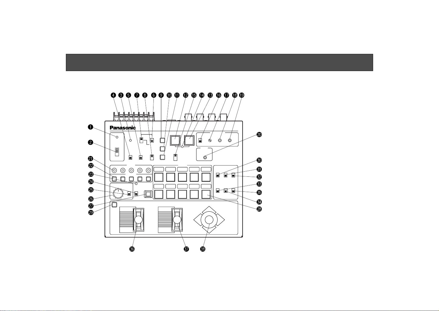
■ Control Panel

-5-
q Power Indicator [POWER]
Lights red when POWER ON/OFF Switch w is in the
ON position, and goes out when the same switch is set
to the OFF position.
w Power CONTROL Switch [POWER, ON/OFF]
All the connected cameras and pan/tilt heads are
switched on when this switch is set to the ON position.
(The power indicator lights.) The camera and pan/tilt
head are partially switched off when this switch is set to
the OFF position.
Note: When the switch is set to the OFF position, the
camera is totally switched off but the communication line between the pan/tilt head and this control
panel remains live. To disconnect all power supply, pull out the power plug from the electrical outlet.
e Operating Indicator [OPERATE]
Lights green when communication begins normally
between the camera and the control panel, and goes
out if a communication error occurs.
r Camera Control Switch [CAM CONT, ON/OFF]
Before making camera settings, select a camera with
CONTROL Switch @2 then set CAM CONT Switch r to
the ON position. After making the necessary settings,
set CAM CON Switch r back to the OFF position.
Note: At the same time as CAM CONT Switch r is set
to the ON position, all the switch settings of this
control panel are sent to the selected camera to
update its settings. Do not shift CAM CONT Switch
r to the ON position except when changing the
camera settings. If a different camera is selected
with CONTROL Switch @2 when CAM CONT Switch
r is in the ON position, the settings of the newly
selected camera will also be changed. Before
selecting another camera with CONTROL Switch
@2, be sure to set CAM CONT Switch r back to
the OFF position.
t Mode Selection Switch [MODE, BAR/CAM]
Used to select camera color bar signals or camera
video signals. Select a camera with CONTROL Switch
@2, set CAM CONT Switch r to the ON position, then
select the desired type of signal with this switch. With
the switch set to BAR, the control panel outputs color
bar signals from the video output terminal. When the
switch is set to CAM, it outputs camera video signals.
After selecting it, set CAM CONT Switch r back to the
OFF position.
y AGC Selection Switch [GAIN, AGC/MANU]
Keep this switch in the AGC position if you want to
keep automatic gain control. Select a camera with
CONTROL Switch @2, set CAM CONT Switch r to the
ON position, then select AGC or MANU as necessary.
When this switch is at AGC GAIN H/M/L switch u is
invalid. After selecting it, set CAM CONT Switch r
back to the OFF position.

-6-
u Gain Selection Switch [GAIN, HIGH/MID/LOW]
This switch is valid only when GAIN AGC/MANU
Switch y is in the MANU position. Select a camera
with CONTROL Switch @2, set CAM CONT Switch r to
the ON position, then select HIGH, MID, or LOW.
Normally, keep it in the LOW position. When the camera is used in a dark place or when video output level
is not high enough even if the iris is wide open, set the
switch to the MID or HIGH position.After selecting it,
set CAM CONT Switch r back to the OFF position.
i Electronic Shutter Speed Selection Switch
[SHUTTER, ELC/ 1/100 /OFF]
Used to select a mode of camera electronic shutter
control. Select a camera with CONTROL Switch @2,
set CAM CONT Switch r to the ON position, then
select ELC, 1/100, or OFF. With the switch in the ELC
position, the electronic shutter is controlled and the
camera sensitivity is automatically adjusted when
using the camera in a bright place. The shutter speed
is 1/100 second when the switch is in the 1/100 position. The electronic shutter is off when the switch is in
the OFF position. After selecting it, set CAM CONT
Switch r back to the OFF position.
o White Balance ATW Selection Switch
[AUTO/ATW, ATW]
When this switch is depressed, the camera selected
with CONTROL Switch @2 keeps automatically adjusting white balance. The switch lights when it is selected.
!0 White Balance Ach Selection Switch
[AUTO/ATW, A]
When this switch is pressed, white balance will be as
stored in Channel A of the camera selected with CONTROL Switch @2. The switch lights when it is selected.
When AWC switch !2 is pressed after selecting
AUTO/ATW, A, white balance is automatically adjusted
and stored in Channel A.
!1 White Balance Bch Selection Switch
[AUTO/ATW, B]
When this switch is depressed, white balance will be as
stored in Channel B of the camera selected with
CONTROL Switch @2. The switch lights when it is
selected. When AWC switch !2 is pressed after
selecting AUTO/ATW, B, white balance is automatically
adjusted and stored in Channel B.
!2 Auto White Start Switch [AWC]
If this switch is pressed when AUTO/ATW A Switch !0
or AUTO/ATW B Switch !1 is selected, white balance is
automatically adjusted on the camera selected with
CONTROL Switch @2. The adjustment results are
stored in Channel A or B. This switch is invalid if the
MODE BAR/CAM switch t is in the BAR position.
Auto Set Indicator !4 flashes while AWC is in operation,
and goes out when white balance has been properly
adjusted. Auto Set Indicator !4 remains lit if white
balance adjustment fails.

-7-
Note: White balance may not be adjustable if there is
no white in the image being taken by the camera.
For details, refer to the Operating Instructions for
the Camera.
!3 Auto Black Start Switch [ABC]
When this switch is depressed, the lens iris is
automatically closed to set black balance on the
camera selected with CONTROL Switch @2. Be sure to
keep the IRIS AUTO/MANU switch @5 in the AUTO
position in setting black balance. Auto Set Indicator !4
flashes while ABC is in operation, and goes out when
black balance has been properly adjusted. Auto Set
Indicator !4 remains lit if black balance adjustment
fails. Black balance adjustment may fail if the total
pedestal is too low. In such a case, adjust the total
pedestal with T.PED Control @0 (referring to the
Operating Procedures at page 26 and try to adjust
black balance again.
!4 Auto Set Indicator
This LED flashes during white balance or black balance adjustment with AWC Switch !2 or ABC Switch !3
depressed, and goes out when the adjustment has
ended normally. The LED remains lit if balance adjustment fails.
!5 Scene File Selection Switch [SCENE FILE, 1/2/3/4]
Select a scene file preset on the camera side.
Remember, however, that [4] is camera scene file
USER A or USER B (provided that or AW-E560 is connected).
!6 Genlock Phase Control Switch
[G/L PHASE, ON/OFF]
Used to adjust the genlock phase in operating the
camera in external sync mode. Select a camera with
CONTROL Switch @2, set CAM CONT Switch r to the
ON position, then set G/L PHASE Switch !6 to the ON
position. After G/L phase setting, set CAM CONT
Switch r and G/L PHASE Switch !6 back to the OFF
position.
Note: If G/L PHASE Switch !6 is set to the ON position
when CAM CONT Switch r is at ON, the genlock
phase setting data of this control panel is sent to
the camera to update its genlock phase settings.
Do not shift G/L PHASE Switch !6 to the ON position except when changing the camera genlock
phase settings. If a different camera is selected
with CONTROL Switch @2 when both CAM CONT
Switch r and G/L PHASE Switch !6 are in the ON
position, the genlock phase settings of the newly
selected camera will be similarly changed. Before
changing the camera for another, set G/L PHASE
Switch !6 back to the OFF position.
!7 Genlock Subcarrier Phase Coarse Switch
[G/L PHASE, 0°/90°/180°/270°]
Used for coarse adjustment of the color phases of genlock input and video output signals in operating the
camera in external sync mode. Used in combination
with G/L PHASE SC Control !8, the switch has an

-8-
adjustment range of over 360°. Before making an
adjustment, set CAM CONT Switch r and G/L PHASE
Switch !6 to the ON position. After the adjustment, set
both CAM CONT Switch r and G/L PHASE Switch !6
back to the OFF position.
!8 Genlock Subcarrier Phase Fine Control
[G/L PHASE, SC]
Used for fine adjustment of the color phases of genlock input and video output signals in operating the
camera in external sync mode. Use this switch in
combination with G/L PHASE Coarse Switch !7.
Before making an adjustment, set CAM CONT Switch
r and G/L PHASE Switch !6 to the ON position. After
the adjustment, set both CAM CONT Switch r and
G/L PHASE Switch !6 back to the OFF position.
!9 G/L Horizontal Phase Adjustment Control
[G/L PHASE, H]
Used to adjust the horizontal phases of genlock input
and video output signals in operating the camera in
external sync mode. Before making a horizontal phase
adjustment, set CAM CONT Switch r and G/L PHASE
Switch !6 to the ON position.
@0 Total Pedestal Level Control [T.PED]
The set pedestal level of the camera’s Y (luminance)
signal can be adjusted. This control is used in a system of two or more cameras to adjust the pedestal levels of these cameras. Select a camera with CONTROL
Switch @2, set CAM CONT Switch r to the ON position, then adjust the total pedestal level with T.PED
Control @00. The control may operate not continuous
sometimes due to digital signal processing. After the
adjustment, set CAM CONT Switch r back to the OFF
position.
@1 Tally Indicator [TALLY]
When a tally signal is input from a special effect generator (SEG) or video switcher, for example, to any of the
jacks [1] to [5] of TALLY Terminal #9, the corresponding LED lights red.
@2 Camera/Pan/tilt Head Selection Switch [CONTROL]
Select a desired camera with pan/tilt head from among
those connected to the control panel. When a camera
with pan/tilt head is selected by pressing one of the
buttons [1] to [5], the pressed button lights.
Note: Even if an unconnected camera with pan/tilt
head is selected by pressing the corresponding
button, the button lights.
@3 Lamp Indicator [LAMP]
Lights red when LAMP ON/OFF Switch @4 is in the ON
position. Flashes if the lamp connected to the AC
adapter (AW-PS300) for the pan/tilt head selected with
CONTROL Switch @2 is broken. Goes out when LAMP
ON/OFF Switch @4 is set to the OFF position

-9-
Caution: In connecting a halogen lamp to the Pan/tilt
Head AC Adaptor (AW-PS300), make sure that it is
in the wattage range of 250 to 500W. If a halogen
lamp less than 250W is used, the LED may flash
when LAMP ON/OFF Switch @4 is in the on position
even if the lamp is normal.
@4 Lamp Switch [LAMP, ON/OFF]
Switches on and off the halogen lamp connected to the
lamp AC receptacle of the pan/tilt head AC adapter
(AW-PS300). Select a pan/tilt head with CONTROL
Switch @2, then switch the halogen lamp on or off as
necessary. Set it to the ON position to switch the halogen lamp on (in which case, the lamp Indicator flashes). Set it to the OFF position to switch the halogen
lamp off.
Note: When a pan/tilt head is selected with CONTROL
Switch @2, the halogen lamp connected to the AC
adapter for the pan/tilt head selected with that
switch lights or goes out depending on the position
of LAMP ON/OFF Switch @4.
@5 Lens Iris Selection Switch [IRIS, AUTO/MANU]
Used to select AUTO or MANU mode in adjusting the
lens iris connected to the selected camera and pan/tilt
head. When this switch is in the AUTO position, the
lens iris is automatically controlled according to the
quantity of light entering the lens. When the switch is in
the MANU position, the iris can be manually controlled
over the range from the closed position to the fully
open position using IRIS LEVEL Control @6.
Set the switch to the MANU position in storing iris data
in PRESET Switch @8 with MEMORY Switch @7. If the
switch is in the AUTO position, iris data will not be
stored in the memory.
@6 Lens Iris Control [IRIS, LEVEL]
When IRIS AUTO/MANU Switch @5 is in the MANU position, the iris can be controlled over the range from the
closed position to the fully open position using this control. Turning it clockwise opens the iris and turning it
counterclockwise closes the iris.
If the camera is preset to AUTO IRIS ADJ ON when
IRIS AUTO/MANU Switch @5 is in the AUTO position,
this control may be used for fine adjustment of ALC
focus level. For details, refer to the Operating
Instructions for the Camera.
If the preset memory is called by pressing PRESET
Switch @8 when IRIS AUTO/MANU Switch @5 is in the
MANU position, the iris is adjusted to the preset value
stored in the memory regardless of the position of this
control. If the control is turned after that, the iris is
adjusted corresponding to the position of the control.
@7 Preset Memory Switch [MEMORY]
Head pan/tilt positions, lens zoom/focus/iris (provided
that IRIS AUTO/MANU Switch @5 is in the MANU position), and camera white balance (ATW, Channel A or B)
can be preset in up to 10 memory buttons per pan/tilt
head.

-10-
To preset them in these buttons, first select a camera
and pan/tilt head with CONTROL Switch @22, then select
a head pan/tilt position, lens zoom/focus/iris, or camera white balance (ATW Channel A or B); press MEMORY Switch @7 (so it lights yellow green and all the 10
buttons of PRESET Switch @8 flash); while keeping the
MEMORY Switch @7 depressed, press one of the 10
buttons of PRESET Switch @8) as desired. The
pressed button in which the selected item is stored
lights.
@8 Preset Position Selection Switch [PRESET]
The head pan/tilt positions, lens zoom/focus/iris, and
camera white balance that are stored in the buttons of
PRESET Switch @8 can be recalled to operate the
pan/tilt head, the lens, and the camera according to
the preset data.
To preset them in the PRESET switches, first select a
camera and pan/tilt head with CONTROL Switch @2,
then select a head pan/tilt position, lens zoom/
focus/iris, or camera white balance (ATW Channel A or
B); press the MEMORY Switch @7 (so it lights yellow
green and all the 10 buttons of PRESET Switch @8
flash); at the same time press one of the 10 buttons of
PRESET Switch @8 as desired. The pressed button in
which the selected item is stored lights.
@9 Speed Selection Switch [SPEED]
If ZOOM lever #6, FOCUS Lever #7, or PAN/TILT Lever
#8 is moved while keeping SPEED Switch @9
depressed, the corresponding operation takes place
at low speed, provided that SPEED SW CHANGE
Switch $9 is in the LOW position. If one of these levers
is moved with SPEED Switch @9 depressed when
SPEED SW CHANGE Switch $9 is in the HIGH position,
the corresponding operation takes place at high
speed. SPEED Switch @9 remains lit while it is kept
depressed.
#0 Defroster Switch [DEF, ON/OFF]
If this switch is connected to a pan/tilt head with a
built-in defroster function, it switches on and off the
defroster.
Note: At the same time as a pan/tilt head is selected
with CONTROL Switch @2, the defroster of the
selected pan/tilt head is switched on or off
depending on the position of DEF ON/OFF Switch
#0.
#1 Wiper Switch [WIP, ON/OFF]
If this switch is connected to a pan/tilt head with a
built-in wiper function, it switches on and off the wiper.
Note: At the same time as a pan/tilt head is selected
with CONTROL Switch @22, the wiper of the selected pan/tilt head is switched on or off depending
on the position of WIPE ON/OFF Switch #1.
#2 Heater/Fan Switch [H/F, ON/OFF]
If this switch is connected to a pan/tilt head with a
built-in heater or fan function, it switches on and off the
heater or fan.
 Loading...