

Panasonic AWE300A, AWE300AP User Manual

Convertible Camera
AW-E300AP
Before attempting to connect or operate this product,
please read these instructions completely.
(Lens : Optional accessory)
This Class A digital apparatus complies with Canadian
ICES-003.
Cet appareil numérique de la classe A est conforme à la
norme NMB-003 du Canada.
WARNING:
TO PREVENT FIRE OR SHOCK HAZARD, DO NOT EXPOSE THIS APPLIANCE TO RAIN OR MOISTURE.
The lightning flash with arrowhead symbol, within an equilateral triangle, is
intended to alert the user to the presence of uninsulated "dangerous voltage"
within the product's enclosure that may
be of sufficient magnitude to constitute a
risk of electric shock to persons.
The exclamation point within an equilateral triangle is intended to alert the user
to the presence of important operating
and maintenance (servicing) instructions
in the literature accompanying the appliance.
The information marking of this product may be found on the
bottom of the unit.
The serial number of this product may be found on the bottom of the unit.
You should note the serial number of this unit in the space
provided and retain this book as a permanent record of your
purchase to aid identification in the event of theft.
Model No. AW-E300A
Serial No.
CAUTION:
TO REDUCE THE RISK OF ELECTRIC SHOCK, DO
NOT REMOVE COVER (OR BACK). NO USER SERVICEABLE PARTS INSIDE.
REFER SERVICING TO QUALIFIED SERVICE PERSONNEL.
CAUTION
RISK OF ELECTRIC SHOCK
DO NOT OPEN
SA 1965
SA 1966
For CANADA
NOTE: This equipment has been tested and found to comply with the limits for a Class A digital device, pursuant to
part 15 of the FCC Rules. These limits are designed to provide reasonable protection against harmful interference
when the equipment is operated in a commercial environment. This equipment generates, uses, and can radiate
radio frequency energy and, if not installed and used in
accordance with the instruction manual, may cause harmful
interference to radio communications. Operation of this
equipment in a residential area is likely to cause harmful
interference in which case the user will be required to correct the interference at his own expense.
For U.S.A

-1-
CONTENTS
PREFACE ................................................................................................................................................................................ 2
FEATURES .............................................................................................................................................................................. 2
SPECIAL NOTES ON OPERATION ......................................................................................................................................... 3
PRECAUTIONS ....................................................................................................................................................................... 4
MAJOR OPERATING CONTROLS AND THEIR FUNCTIONS ................................................................................................. 6
MOUNTING ............................................................................................................................................................................ 10
FLANGE BACK ADJUSTMENT ............................................................................................................................................... 12
IRIS GAIN CONTROL IN A LENS ........................................................................................................................................... 13
CONNECTIONS ...................................................................................................................................................................... 14
ADJUSTMENT ........................................................................................................................................................................ 20
USE MODE SETTING ............................................................................................................................................................. 27
MENU ITEM SETTING ............................................................................................................................................................ 29
SETTING TO INITIAL SET ....................................................................................................................................................... 46
APPEARANCE ........................................................................................................................................................................ 49
SPECIFICATIONS ................................................................................................................................................................... 50
STANDARD ACCESSORIES ................................................................................................................................................... 52
OPTIONAL ACCESSORIES .................................................................................................................................................... 52

-2-
The Panasonic AW-E300A is a digital signal processing
color video camera that incorporates three 1/3” CCDs.
A digital video signal processing system is packed in a
compact, lightweight body while assuring high picture
quality, high reliability and high performance.
System setup and adjustments can be easily performed
1. Digital video signal processing for high quality, high
reliability, high performance, lightweight and compact size.
2. Resolution: 850 lines (HIGH BAND DTL: ON), S/N
ratio: 65 dB (DNR ON)
3. Minimum illumination: 1.5 lux (F1.4, Night eye
mode)
4. SET UP menu for system check and readjustments.
5. Built-in automatic controls, including ATW, ELC,
and AGC
6. CCD readout is switchable between field and frame
PREFA CE
FEATURES
by following the setup menu.
Connection to peripheral devices, such as a RCU, a
RCB and a lens and the camera pan/tilt unit enables a
wide variation of system configurations.
Option cards may also be installed.
modes. Vertical resolution can be stepped up in
frame mode and it is effective for shooting still
objects.
7. The built-in synchronized scanning system reduces
noise in computer graphics.
8. Various correction circuits permit video reproduction with high fidelity.
9. Chroma detail correction enables clear shots of
dark color objects.
10. A dark detail circuit provides natural edge correction to any object in a dark scene.
The suffix P is omitted from some model numbers given in these Operating Instructions (ex.: AW-E300AP → AW-E300A).

-3-
11. A digital highlight chroma circuit reproduces natural
dynamic ranges.
12. A digital color matrix enables high fidelity color
images.
13. Four use modes for each of your specific applications can be selected.
14. SMPTE color bar is indicated on the monitor screen.
15. Remote control with a RCU, RCB or a Hybrid control panel.
• Turn power off before connecting or disconnecting
cables.
• Connection or disconnection of any studio cable,
RCB cable or other cable to any unit of equipment
must be performed while power is off.
• While the camera is in automatic mode;
Shooting of bright objects in ELC operation mode
may result in a smeared picture unique to the CCD.
The ATW function under fluorescent illumination can
adversely change the white balance.
SPECIAL NO TES ON OPERATION

-4-
DONT'S
• Do not attempt to disassemble the camera, Remote
Control Unit (RCU) or other units. In order to prevent electric shock, do not remove screws or covers. There are no user-serviceable parts inside.
• Do not abuse the camera. Avoid striking, shaking,
etc. The camera contains sensitive components
which could be damaged by improper handling or
storage.
• Do not let the lens remain uncapped when the camera is not in use. If the lens is not installed, do not
leave the lens mount hole uncovered.
• Do not touch the surface of the lens or prism.
• Do not use strong of abrasive detergents when
cleaning the camera body.
• Do not aim the camera toward the sun, no matter
whether it is turned on or not.
• Do not expose the camera or Remote Control Unit
(RCU) to rain or moisture, and do not try to operate
the equipment in wet conditions. Do not operate the
camera or RCU if it becomes wet.
• Do not operate the camera or Remote Control Unit
(RCU) outdoors during a lightning storm.
• Do not use the camera in an extreme environment
where high temperatures or high humidity exist.
• Do not leave the camera and Remote Control Unit
(RCU) turned on when not in use. Do not unnecessarily turn the camera power on and off repeatedly.
Do not block the ventilation slots.
PRECA UTIONS

-5-
• Take immediate action if ever the camera or RCU
should become wet. Turn the power off and have
the unit checked by an authorized service facility.
• Follow normal safety precautions to avoid personal
injury.
• Use the camera in an environment where the tem-
perature is within −10°C - +45°C (14°F - 113°F),
and the relative humidity is within 30 % - 90 %.
• Always turn the power off when the camera is not
going to be used. Operate the camera and RCU
only when there is adequate ventilation.
DO'S
• Refer any servicing to qualified service personnel.
• Handle the camera with care.
• Protect the precision made lens by placing the lens
cap over when the camera is not in use. If the lens
is not installed, protect the surface of the prism by
placing the body cap into the lens mount hole.
• Use a mild blower or lens cleaning tissue designed
for coated lenses, to clean the surface of the lens or
prism in the event that it should become dirty.
• Use a dry cloth to clean the camera if it is dirty. In
case the dirt is hard to remove, use mild detergent
and wipe gently.
• Use caution when operating the camera in the
vicinity of spot lights or bright lights, as well as light
reflecting objects and surfaces.
Convertible Camera AW –
FOCUS
LOCK
87A00001
SER
NO
-6-
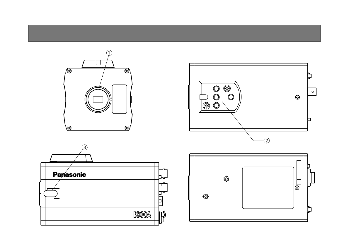
<Front View> <Top View>
<Bottom View><Side View>
MAJOR OPERATING CONTROLS AND THEIR FUNCTIONS

-7-
3. Flange-back Adjustment Screws (FOCUS/LOCK)
When flange-back adjustment is necessary, loosen
the lock screw and turn the focus screw to adjust
the flange-back.
4. MENU Switch (MENU/ )
A menu will appear on the monitor screen when this
switch is pressed for about 5 seconds. This item
can be selected by pressing the switch while the
menu is on the screen.
5. ITEM/AWC Switch (ITEM/AWC/ )
The item just below can be selected by pressing
this switch while the menu is on the screen. When
the menu is not displayed or the camera is in shooting mode, the automatic white balance control can
be set with this switch.
6. YES/ABC Switch (YES/ABC/+)
The Sub Menu for each item of the Main Menu is
displayed when this switch is pressed while the
Main Menu is on the screen.
While the Sub Menu is displayed, any setting can
be brought up to a higher value with this switch.
When the menu is not displayed or the camera is in
shooting mode, the automatic black balance control
can be set with this switch.
–
+
MENU
ITEM/AWC
YES/ABC
NO/BAR
OPTION CARD
VIDEO OUT
I/F REMOTE
G/L IN
IRIS
DC12V IN
1. Lens Mount
1/3" C mount type lens or a microscope adaptor
can be mounted.
2. Mounting Adaptor
A screw hole (1/4” - 20 UNC) adaptor for mounting
the camera on a wall, ceiling with a mounting
bracket or tripod.
➞
➞

-8-
Pin No. Signal Pin No. Signal
1 Return Control 7 Iris Follow
2 Not Used 8 Auto/Remote Control
3 GND 9 Not Used
4 Auto/Manual Control 10 Not Used
5 Iris Control 11 Not Used
6 Lens Power 12 Not Used
<Front View>
Iris Connector (IRIS)
o
q
i
w
u
e
ytr
!2
!0
!1
10. I/F Remote Connector (I/F REMOTE)
Input terminal dedicated to control signals from the
optional Remote Control Box (RCB) (WV-CB700A)
and the RCU (WV-RC700A, WV-RC550) and the
camera pan/tilt unit (AW-PH300).
* WV-CB700A is connected through the optional RCB
cable (AW-CA50T10).
* WV-RC700A/WV-RC550 is connected through the
optional RCU cable (AW-CA50A26).
* AW-PH300 is connected through the optional pan/
tilt unit cable (AW-CA50T15).
11. Power Indicator
Red LED lamp lights to indicate that the specified
DC power is supplied to the camera.
7. NO/BAR Switch (NO/BAR/−)
The item just below can be selected by pressing
this switch while the Sub Menu is on the screen.
While the Sub Menu is displayed any setting can be
brought down to a lower value with this switch.
When the menu is not displayed or the camera is in
shooting mode, the color bar and the shooting conditions are alternately indicated by pressing the
switch.
8. Video Output Connector (VIDEO OUT)
A composite video signal is provided at this connector.
9. Iris Connector (IRIS)
Input terminal for lens with an iris control function.

-9-
13. Cable Clamp
Clamp the DC Power Supply Cable (AW-CA4T1)
connected to the DC 12 V Input Connector to prevent it from slipping out.
14. G/L Input Connector (G/L IN)
Signals synchronized with the reference signal are
to be supplied to this connector when the camera is
to be synchronized with the reference signal BB.
15. Optional Card Slot
Slot for inserting an optional card. For details, refer
to the manual for optional cards.
12. DC 12 V Input Connector (DC 12V IN)
12 V DC is supplied through the optional DC power
supply cable (AW-CA4T1).
-10-
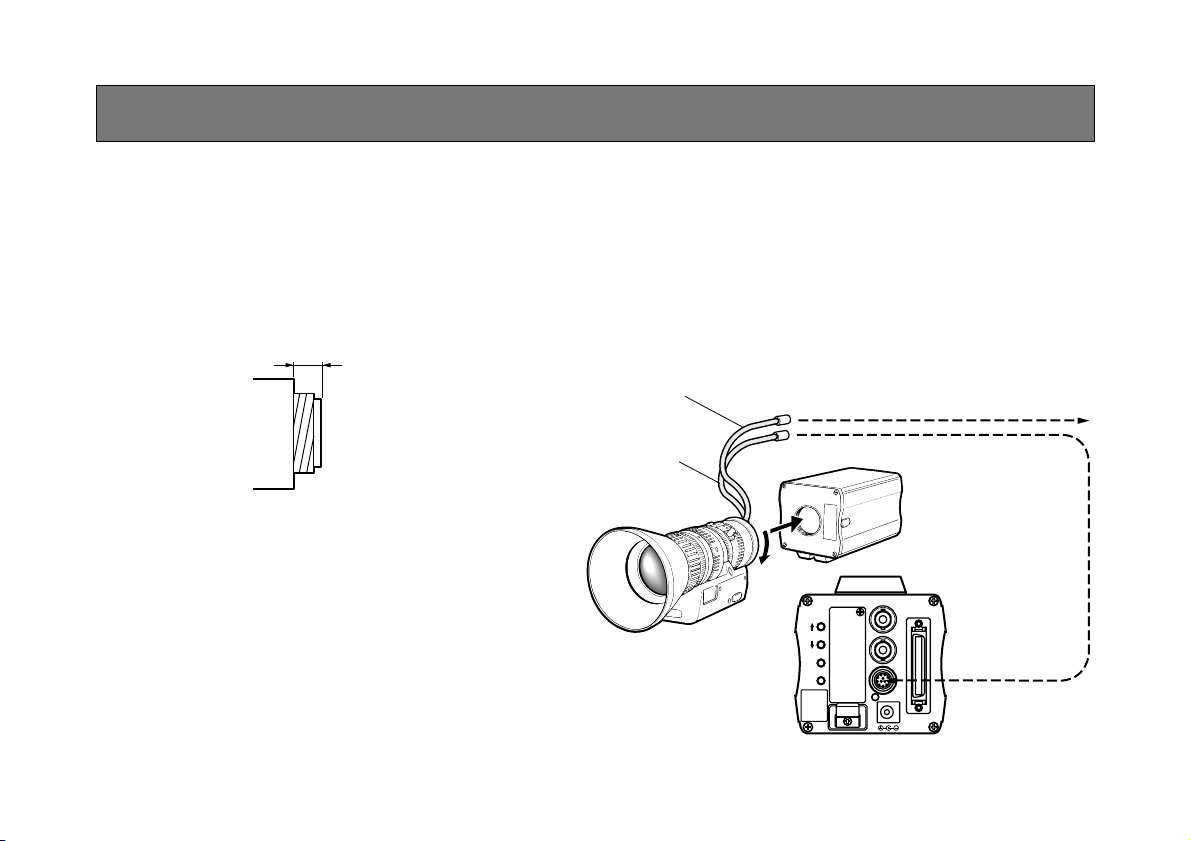
• 1/3” C mount type lens can be mounted on the
camera.
• There may be a danger of damage to the camera
depending on the type of lens. Use a lens whose
mount screw height is 4.3 mm or less.
–
+
MENU
ITEM/AWC
YES/ABC
NO/BAR
OPTION CARD
VIDEO OUT
I/F REMOTE
G/L IN
IRIS
DC12V IN
Control Cable
To Lens I/F Connector of
Camera Pan/tilt Unit
Camera Cable
To Iris Connector
1. Lens Mounting
Remove the body cap from the camera by pulling
on it.
Attach the lens into the lens mount and turn the lens
clockwise to hold the lens securely. Connect the
camera cable to the IRIS connector on the back
panel of the camera.
• Refer also to the manual for the lens because the
mounting procedures may differ depending on the
lens.
4.3 mm or less
MOUNTING

-11-
2. Fix the camera mounting base, pan/tilt unit, and tripod securely in the screw hole (1/4-20UNC) of the
camera mounting adaptor.
3. If the camera cannot be securely fixed, stick the
supplied rubber sheet to the mounting adaptor,
then mount the camera.
Mounting adaptor
2. Camera Mounting
1. Fix the mounting adaptor to the top or bottom of the
camera.
Camera Mounting Bracket (WV-831)
When changing the camera mounting adapter, use a
screwdriver or similar tool to tighten the screws firmly.
$
Preventing the camera from falling or coming off
O
When attaching a camera to the pan/tilt head (AWPH300A), follow the directions in the Operating Instructions
to fix the camera firmly in position.
In addition, link the camera to the pan/tilt head using the
safety chain and the mounting screws to help ensure the
camera does not fall.
O
When attaching the camera on any mounting or other
pan/tilt head, check that the mounting can safely bear the
total weight of the camera, lens, connection cables, etc., fix
the camera firmly in position using the prescribed tool, and
take appropriate measures to prevent the camera from
falling.

-12-
1. Fully open the iris by shooting a dark object. (Iris
selection switch should be set to M.)
2. Remove the cap from the camera’s Flange-back
Adjustment Screws.
3. Loosen the flange back lock screw.
4. Aim the camera at any object over 2 meters away
from the camera.
5. Set the lens to its TELE end first and adjust its focus
with the focus ring.
6. Set the lens to its widest angle next and adjust its
focus with the focus screw.
7. Adjust the focus ring and the focus screw alternately for the best focus within the zooming range.
Tighten the lock screw upon completion of focusing.
8. Turn the iris selection switch to Position A.
Convertible Camera AW –
FOCUS
LOCK
3.3 4 5 7
2
5.5 10
1.51.21
FOCUS Ring
FOCUS Screw
LOCK Screw
FLANGE BACK ADJUSTMENT

-13-
IRIS GAIN CONTROL IN A LENS
An iris gain control hole is usually provided in the front
of the lens. Adjustment of the iris gain, with a screwdriver through the hole may be done as follows. (Shape
and location of the hole may vary depending on the
type of lens.)
1. Turn the iris selection switch to Position A (AUTO).
2. Rotate the iris gain control to the maximum gain,
but in a range where no hunting or oscillating of the
iris ring develops.
Iris gain control (G, S)
Automatic iris power zoom lens

-14-
Caution:
The connection and installation should be done by qualified service personnel or system installers.
Refer any servicing to qualified service personnel.
CONNECTIONS
PS505
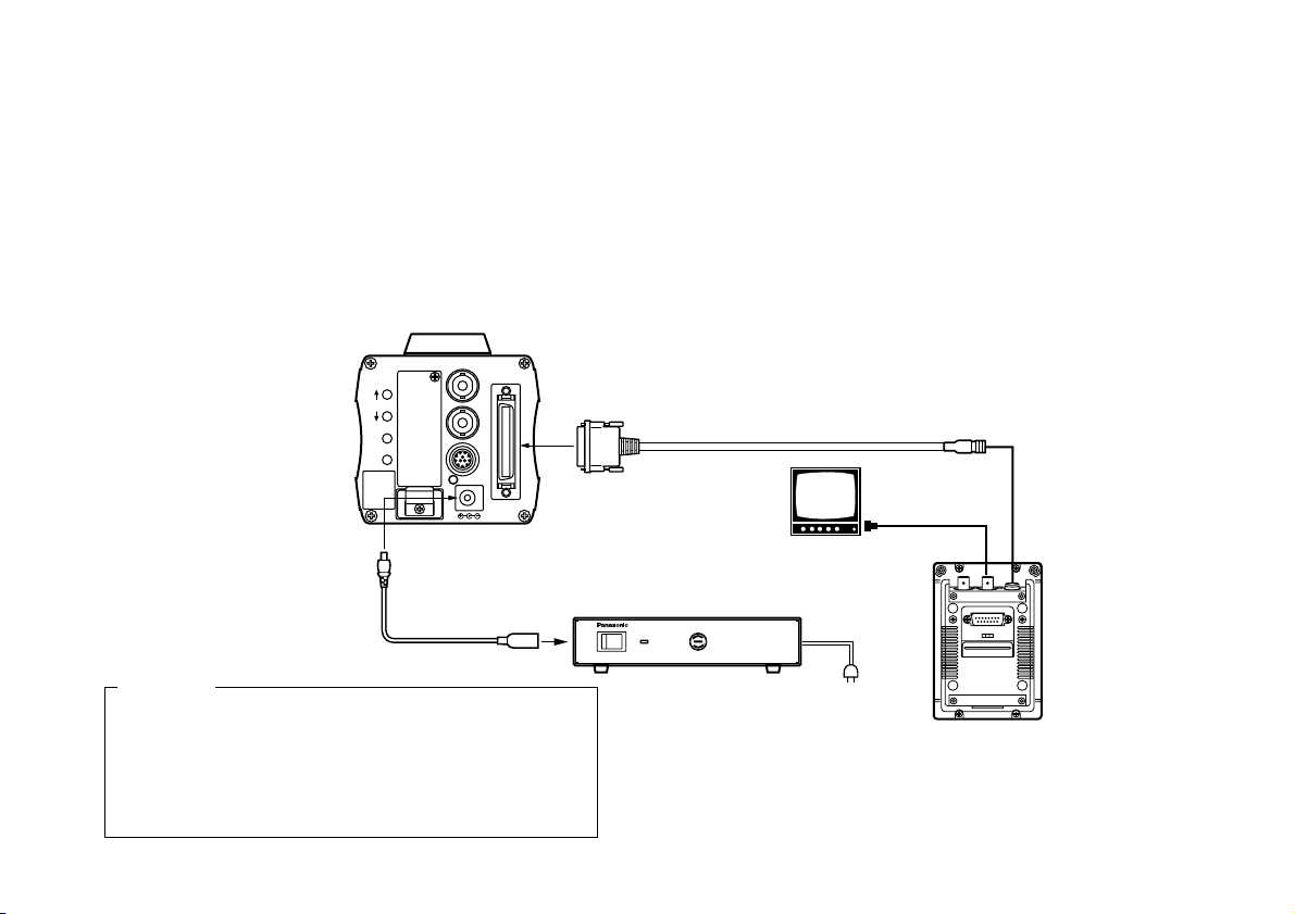
■ CONNECTION OF DEVICE WITH A COMPOSITE INPUT CONNECTOR
1. Connect this to a DC 12 V class 2 power supply only.
2. To prevent fire or shock, the UL listed wire VW-1, style 1007 should be used as for the cable for DC 12 V Input
Connector.
Cautions
• Connection to any device which has a composite input connector, such as a video monitor or a VCR, must be made
through the VIDEO OUT Connector.
• Power supply to the camera must be through the optional DC power supply Cable AW-CA4T1.
• For DC power supply, use the optional AC adaptor AW-PS505.
VIDEO OUT
Connector
Video monitor
AC Adaptor AW-PS505
VIDEO IN
75 Ω coaxial cable
DC Power supply
Cable AW-CA4T1
POWER
O I
POWER
ON
FUSE(POWER)
FUSE
FUSE
AC Adaptor
AW-
MENU
ITEM/AWC
YES/ABC
+
NO/BAR
–
OPTION CARD
VIDEO OUT
G/L IN
IRIS
DC12V IN
I/F REMOTE
OFF

-15-
–
+
MENU
ITEM/AWC
YES/ABC
NO/BAR
OPTION CARD
VIDEO OUT
I/F REMOTE
G/L IN
IRIS
DC12V IN
GEN-LOCKGEN-LOCKINAUXAUX
IN
AUTOAUTO
7575Ω/Hi-Z/Hi-Z
AUTOAUTO
7575Ω/Hi-Z/Hi-Z
R/PR /CR/PR /C
OUTOUT OUTOUT
AUDIOAUDIO
SEE MANUAL
VIDEO 1VIDEO 1
G/Y/YG/Y/Y VIDEO 2VIDEO 2
B/PB /BB/PB /B SYNCSYNC
S-VIDEOS-VIDEO
1 4
2 3
TALLYTALLY
CAMERA (MULTI)CAMERA (MULTI)
CABLE SELECTCABLE SELECT
FUSEFUSE
250V 1.25A250V 1.25A
TALKTALK
INCOMINCOM
RECEIVERECEIVE
CONTROL
TALLY & INCOMTALLY & INCOM
MULTI OVPOVP
MPXMPX
MPXMPX
OUTPUT
Connection to the RCU (WV-RC700A,WV-RC550) is
made through the optional RCU cable AW-CA50A26.
1. Turn RCU power off before connecting cables.
2. Set the cable selection switch of the RCU to MULTI
(in case of using the WV-RC700A)
3. Connect the 50-pin connector of the RCU cable to
the I/F REMOTE Connector of the camera.
4. Turn RCU power on and the power indicator lamp
will light. The camera can now be remote controlled by the RCU.
Notes:
• The maximum extension distance between the
camera and WV-RC700A is 300 m. The maximum
extension distance between the camera and WVRC500 is 100 m.
• Use the following options for cable extension.
Studio Cable WV-CA26U15 (15 m/50 ft)
WV-CA26U30 (30 m/100 ft)
WV-CA26U100 (100 m/330 ft)
Cable Joint Adaptor
WV-CA26T26
■ CONNECTION OF A REMOTE CONTROL UNIT (RCU)
Set to MULTI
WV-RC700A
RCU Cable
AW-CA50A26 (15 m)
-16-
–
+
MENU
ITEM/AWC
YES/ABC
NO/BAR
OPTION CARD
VIDEO OUT
I/F REMOTE
G/L IN
IRIS
DC12V IN
ALL 1
2
USER SET
ON
POWER
OFF
POWER
O I
FUSE(POWER)
FUSE
FUSE
AC Adaptor
AW-
PS505
■ CONNECTION OF A REMOTE CONTROL BOX (RCB)
The RCB (WV-CB700A) and the camera must be connected with the optional RCB cable AW-CA50T10.
1. Turn RCB power off before connecting cables.
2. Connect the 50-pin connector of the RCB cable to
I/F REMOTE connector of the camera. The 10-pin
connector must be connected to the RCB.
3. Turn RCB power on and the camera can be controlled remotely by the RCB.
Notes:
• The monitor output signals of the RCB attenuate
and deteriorate with cable length. It is recommended that the signals from the monitor output be used
for monitoring purposes only.
• No gen-lock signal is available from the RCB.
AC Adaptor
AW-PS505
Video signal IN
RCB WV-CB700A
1. Connect this to a DC 12 V class 2 power supply
only.
2. To prevent fire or shock, the UL listed wire VW-1,
style 1007 should be used as for the cable for DC
12 V Input Connector.
Cautions
RCB Cable AW-CA50T10 (3 m)
MONITOR OUT
DC Power Cable
AW-CA4T1
RCB
 Loading...