

Panasonic AK-HCU931 User Manual
Model AK-HCU931P
Before attempting to connect, operate or adjust this product, please read
these instructions completely.
Camera Control Unit
C
A
B
L
E
O
P
E
N
S
H
O
R
T
A
L
A
R
M
F
U
S
E
1
25
V
5
A
M
A
I
N
TALLY/CALL
F
U
S
E
2
50V
5A
L
E
V
E
L
P
G
H
M
E
P
1
A
G
D
M
P
O
W
E
R
O
F
F
P
G
M
S
2
Y
S
T
E
M
PUSH
P
R
IV
A
T
E
M
IC
ON
OFF
PTT
Camera Control Unit
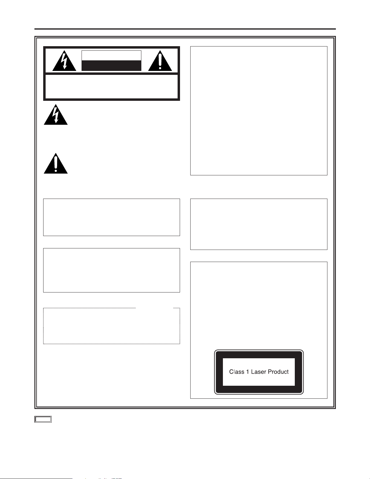
Safety precautions
2
CAUTION
RISK OF ELECTRIC SHOCK
DO NOT OPEN
CAUTION: TO REDUCE THE RISK OF ELECTRIC SHOCK,
DO NOT REMOVE COVER (OR BACK).
NO USER SERVICEABLE PARTS INSIDE.
REFER TO SERVICING TO QUALIFIED SERVICE PERSONNEL.
The lightning flash with arrowhead symbol,
within an equilateral triangle, is intended to
alert the user to the presence of uninsulated
“dangerous voltage” within the product’s
enclosure that may be of sufficient magnitude
to constitute a risk of electric shock to persons.
The exclamation point within an equilateral triangle is intended to alert the user to the presence of important operating and maintenance
(service) instructions in the literature accompanying the appliance.
WARNING:
TO REDUCE THE RISK OF FIRE OR SHOCK
HAZARD, DO NOT EXPOSE THIS EQUIPMENT TO RAIN OR MOISTURE.
This class A digital apparatus complies with
Canadian ICES-003.
Cet appareil numérique de la classe A est
conforme à la norme NMB-003 du Canada.
CAUTION:
TO REDUCE THE RISK OF FIRE OR SHOCK
HAZARD AND ANNOYING INTERFERENCE,
USE THE RECOMMENDED ACCESSORIES
ONLY.
FCC Note:
This device complies with Part 15 of the FCC Rules.
To assure continued compliance follow the attached
installation instructions and do not make any unauthorized modifications.
This equipment has been tested and found to comply
with the limits for a class A digital device, pursuant to
Part 15 of the FCC Rules. These limits are designed
to provide reasonable protection against harmful interference when the equipment is operated in a commercial environment. This equipment generates, uses,
and can radiate radio frequency energy and, if not
installed and used in accordance with the instruction
manual, may cause harmful interference to radio communications. Operation of this equipment in a residential area is likely to cause harmful interference in
which case the user will be required to correct the
interference at his own expense.
indicates safety information.
For CANADA
CAUTION:
This product uses a semiconductor laser system
and is a laser class 1 product complies with
Radiation Performance Standards, 21CFR SUBCHAPTER J.
Use of controls or adjustments or performance of
procedures other than those specified herein
may result in hazardous radiation exposure.
Don’t make any modifications.
Don’t repair by yourself.
Refer servicing to qualified personnel.
CAUTION:
Invisible Laser radiation is emitted from the
Optical fiber connector when this product is
turned on.
Don’t look into directly into the Optical fiber
connector of this product.

3
Contents
Safety precautions . . . . . . . . . . . . . . . . . . . . . . . . . . . . . . . . . . . . . . . . . . . . . . . . . . . . . . . . . . 2
Overview . . . . . . . . . . . . . . . . . . . . . . . . . . . . . . . . . . . . . . . . . . . . . . . . . . . . . . . . . . . . . . . . . 3
Accessories . . . . . . . . . . . . . . . . . . . . . . . . . . . . . . . . . . . . . . . . . . . . . . . . . . . . . . . . . . . . . . . 3
Operating precautions . . . . . . . . . . . . . . . . . . . . . . . . . . . . . . . . . . . . . . . . . . . . . . . . . . . . . . . 3
Parts and their functions . . . . . . . . . . . . . . . . . . . . . . . . . . . . . . . . . . . . . . . . . . . . . . . . . . . . . 4
Connections . . . . . . . . . . . . . . . . . . . . . . . . . . . . . . . . . . . . . . . . . . . . . . . . . . . . . . . . . . . . . . 11
External dimension drawing . . . . . . . . . . . . . . . . . . . . . . . . . . . . . . . . . . . . . . . . . . . . . . . . . . 13
Specifications . . . . . . . . . . . . . . . . . . . . . . . . . . . . . . . . . . . . . . . . . . . . . . . . . . . . . . . . . . . . . 14
Overview
By connecting this unit to the multi-format camera (model AK-HC931P), multi-format images can be input and output. (Some
of the functions are available as options.)
The unit is connected to the multi-format camera, and it is connected to the remote operation panel (ROP) and master setup
unit (MSU) using dedicated multi-purpose cables (available as optional accessories).
When the designated multi-purpose cables are used, the distance between from the CCU to the ROP and MSU can be
extended up to 50 meters.
Accessories
Rack-mounting adapters (k2)
Mounting screws (M4k8 mm) (k6)
BNC termination resistor (k1)
Communication connector (k1)
Power cord (k1)
Operating precautions
O Handle the unit carefully.
Dropping the unit or subjecting it to strong impact may cause malfunctioning and/or accidents.
O Operate the unit within a temperature range of 32oF to 104oF (0oC to i40oC).
Operation in locations below 32oF or above 104oF may adversely affect the internal parts.
O Be absolutely sure to turn off the power before connecting or disconnecting the
cables.
O Do not use the unit outdoors.
O Install the unit at a distance of at least 3.3 ft (1 meter) from the monitor.
O Maintenance
Disconnect the power plug, and wipe the unit with a dry cloth. To remove stubborn dirt, soak a cloth in diluted kitchen
detergent and wring it out well, and then wipe the unit gently.
O
Avoid using benzine, paint thinners or other volatile substances.
O
If a chemically treated cloth is to be used, read the precautions for its use carefully.
Caution
4
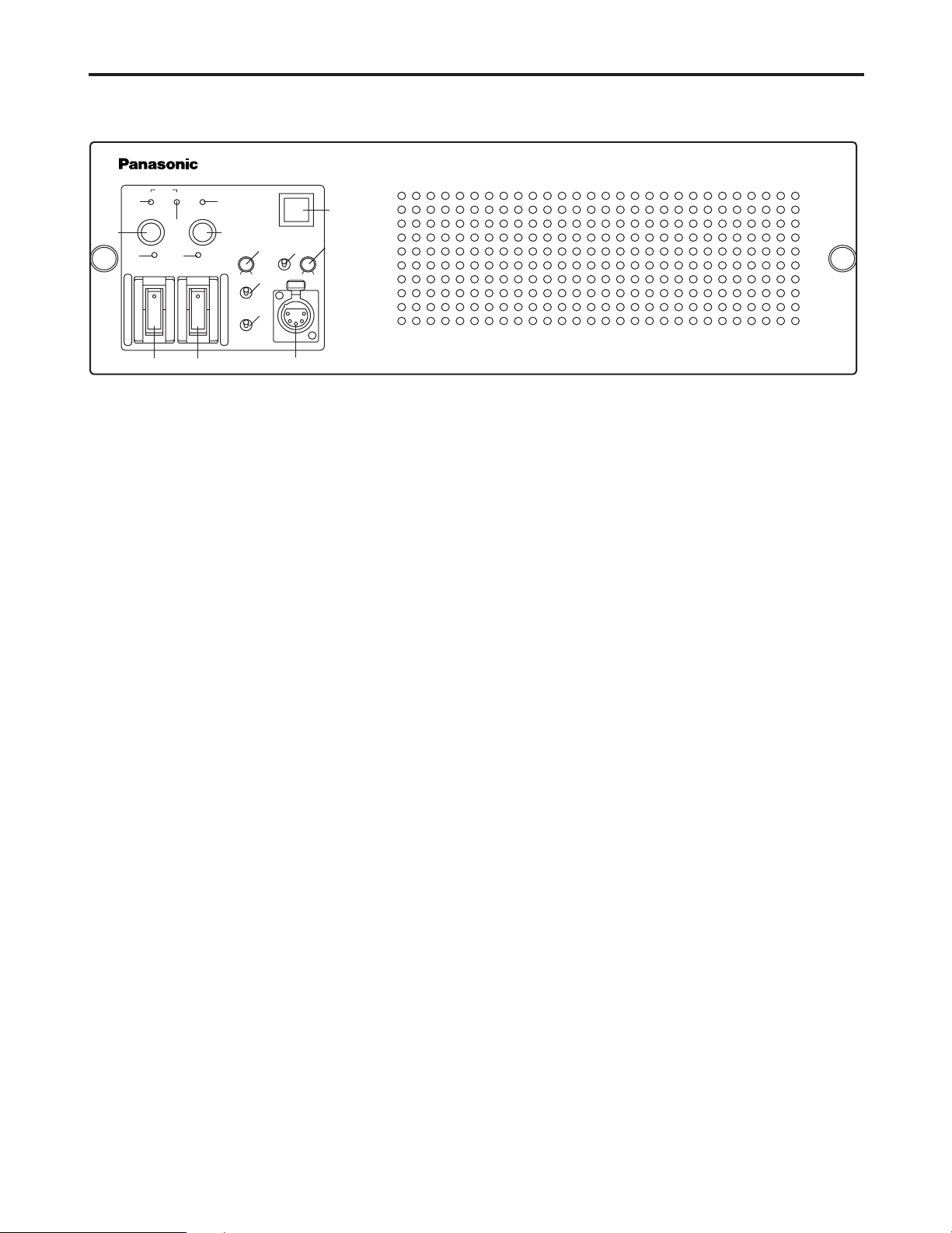
Parts and their functions
1 CCU power switch [MAIN]
This is the power switch of the camera control unit
(CCU). The CCU, ROP and other units will not operate
unless this switch is set to ON.
Up: ON
Down: OFF
2 Camera power switch [HEAD POWER]
This switch supplies power to the camera. However, if
the ROP has been connected, power is supplied to the
camera only when this switch and the camera power
switch on the TOP are both set to ON.
Up: ON
Down: OFF
3 CCU power ON LED
Lighted: The CCU power is ON.
Off: The CCU power is OFF.
4 Camera power ON LED
Lighted: This indicates that power is being supplied from
the CCU to the camera.
Off: This indicates that power is not being supplied
from the CCU to the camera.
Even if the camera power switch is ON, this LED remains
off if no power is supplied to the camera.
This is due to one of the following reasons: 1 the supply
of power to the camera has been turned off by the ROP,
2 one of the optical fiber cables has been disconnected
or 3 something is wrong with the camera, and the power
supply was turned off.
5 CCU power fuse
This is the CCU main power fuse.
6 Camera head power fuse
This is the camera head power supply fuse.
7 Alarm LED [ALARM]
Lighted: This LED indicates that the CCU’s fan has
stopped and that something is wrong with the
power supply.
Off: Normal
If the LED remains lighted, turn off the main power and
have the unit repaired.
8 Camera cable open alarm LED [CABLE / OPEN]
Lighted: The cable between the CCU and camera has
been disconnected.
Off: Normal
9 Camera cable short-circuit alarm LED
[CABLE / SHORT]
Lighted: The cable between the CCU and the camera has
short-circuited.
Off: Normal
: TALLY indicator/CALL switch [TALLY/CALL]
This indicator lights when the R/G tally signal is input. It
is also a CALL switch for calling the camera, ROP and
MSU.
; INCOM volume control [LEVEL]
This is used to adjust the standby INCOM volume.
< INCOM PGM selector switch
This is used to select the PGM input signals which are to
be mixed with the standby INCOM.
= INCOM PGM level control [PGM]
This is used to select the level of the PGM signals which
are to be mixed with the standby INCOM.
> INCOM selector switch
This is used to select the call party of the standby
INCOM.
PRIVATE: For making private calls to the camera.
COMM: For connecting the standby INCOM with the
system INCOM.
? INCOM MIC selector switch [MIC]
ON: The INCOM microphone is set to ON.
OFF: The INCOM microphone is set to OFF.
PTTN: The INCOM microphone is set to ON only while
the INCOM MIC selector switch is held down.
@ Standby INCOM jack
This is connected to INCOM 1 line, and it enables calls to
be made to the camera’s INCOM 1 line.
Even when the camera power is OFF, calls can still be
made to the camera’s INCOM 1 line.
$ Camera control unit front panel
12
3
4
5
6
78
9
:
;
<
=
>
?
@
CABLE
TALLY/CALL
OPEN
FUSE
MAIN HEAD POWER
125V 5A
FUSE
LEVEL PGM
PGM 1
SYSTEM
PRIVATE
MIC
ON
PTT
OFF
OFF
PGM 2
250V 5A
SHORT ALARM
Camera Control Unit
PUSH
5
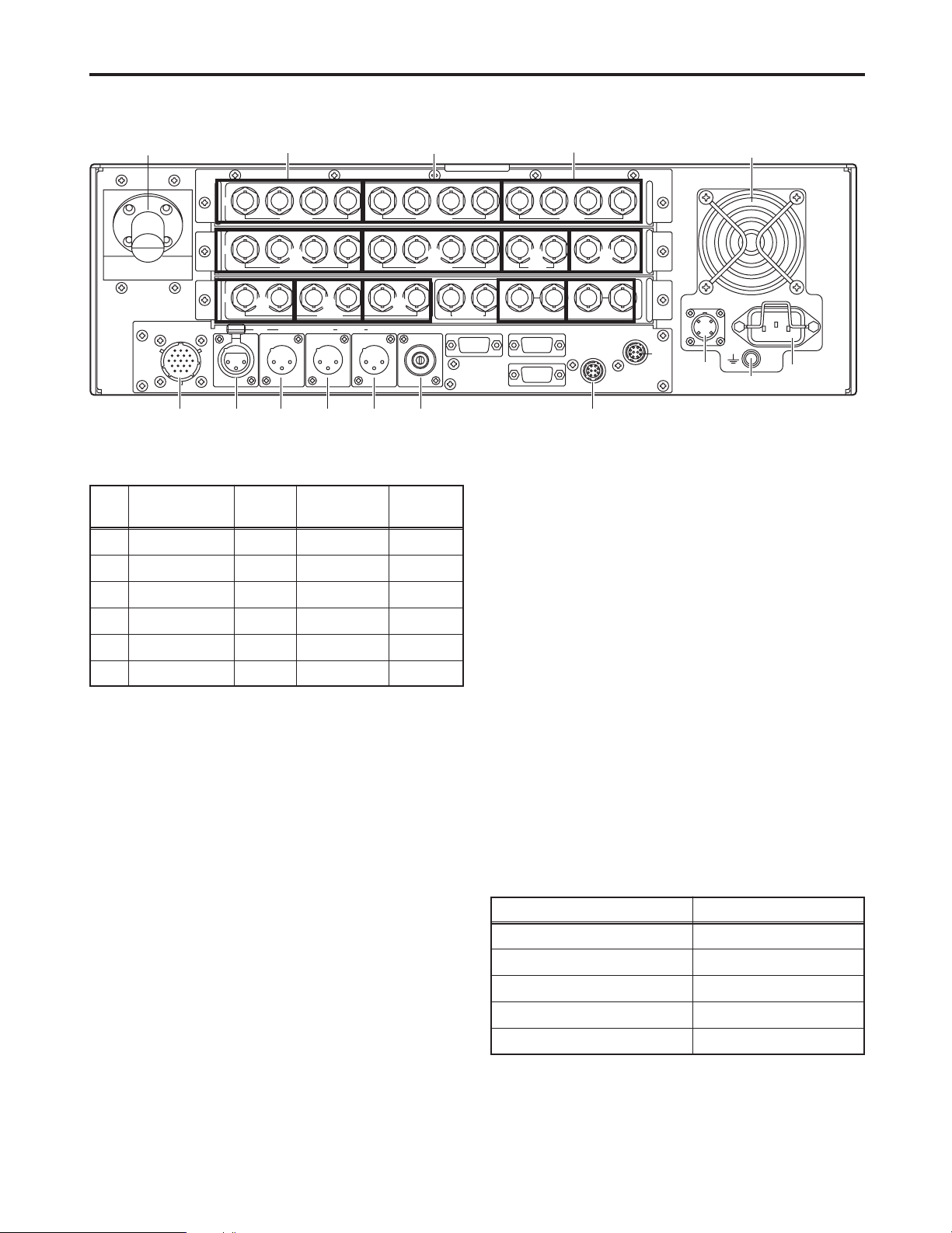
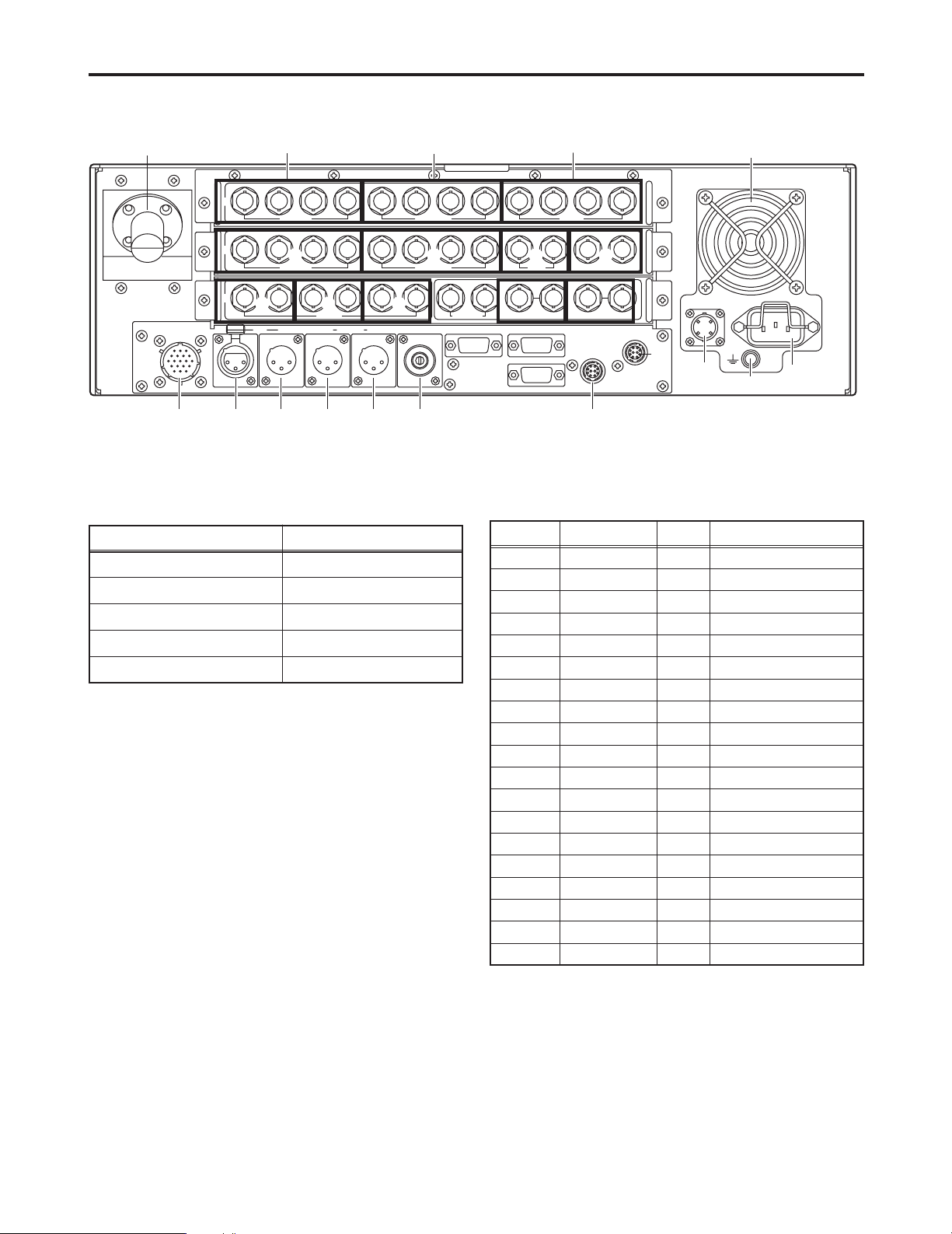
Parts and their functions
$ Camera control unit rear panel
A
B
C
PQRSTU
V
W
X
Y
Z
[
\
^
]
L
M
NO
12
PUSH
HD
RET1
SDI INPUT SDI OUTPUT
RET2 RET3 RET4 OUT1 OUT2 OUT3
OUT4/PM Y / G Pb / B Pr / R PM
HD
OUTPUT
SD
RET1
SDI INPUT SDI OUTPUT
RET2 RET1 RET2
PROMPT
RET3 RET4 OUT1 OUT2 OUT3 OUT4
SD
COMMUNICATION
WFM1
IN RTS
OUT CH–1 CH–2
DIGITAL AUDIO
TRUNK WFM CONTROL
AUX
ROP
CSU / MSU
ALARM
GND
MIC OUT
WFM2 PM1 PM2 VBS1 VBS2 HD HD REFSD
SD
OUTPUT
INPUT 1 2
SYNC OUTPUT
SD REF
AC IN
F
E
GH
I J K
D
ROP/MSU monitor selection SDTV WFM output
RR
GG
BB
RGB 3 waveformsSEQ
Composite videoENC
Pin
No.
Function
Optical fiber
Polarity Signal flow
CAM#CCU
Cable color
Yellow (01)1
Optical fiber
CCU#CAM
Yellow (02)2
Control wire, hot
i CAM,.CCU
Black3
Control wire, cold
j CAM,.CCU
Red4
AC 240 V live
i CCU#CAM
Orange5
AC 240 V neutral
j CCU#CAM
White6
E SDTV digital return video 1, 2, 3, 4 input connectors
[SDTV DIGITAL RET 1, 2, 3, 4]
These connectors are for inputting the return video signals of the SDTV serial digital interface.
F SDTV D1 digital video output connectors
[SDTV DIGITAL OUT D1 1, 2 3]
These connectors are for outputting the D1 format video
signals of the SDTV serial digital interface.
There are 3 connectors (BNC).
G Analog return video 1, 2 input connectors
[ANALOG RET 1, 2]
These connectors (BNC) are for inputting the SD analog
return video signals.
H PROMPT-IN connectors [PROMPT1,2]
These are the prompter signal input connectors (BNC).
Input SDTV composite video signals as the prompter signals.
I SDTV waveform monitor output connectors
[SDTV WFM 1, 2]
These connectors (BNC) are for outputting the camera
video signals which are to be displayed on the SDTV
waveform monitor.
B HDTV digital return video 1, 2, 3, 4 input connectors
[HD DIGITAL RET 1, 2, 3, 4] (Option)
These connectors (BNC) are for inputting the return video
signals of the HDTV serial digital interface.
C HDTV digital video 1, 2, 3, 4 output connectors
[HD DIGITAL OUT 1, 2, 3, 4] (Option)
These connectors (BNC) are for outputting the video signals of the HDTV serial digital interface.
D HDTV analog component video output connectors
[HDTV ANALOG Y/G, Pb/B, Pr/R] (Option)
The HDTV analog signals of the camera are output from
these connectors (BNC).
G/B/R or Y/Pb/Pr video signals can be selected by the
master setup unit (MSU) or remote operation panel
(ROP).
SDTV PM output connector [PM]
This is the HDTV PM output (1Vp-p) connector.
A Optical fiber connector
FXW.3K.93C.CLM made by LEMO
6
Parts and their functions
J SDTV picture monitor video output connectors
[PM 1, 2]
These connectors (BNC) are for outputting the video signals
which are to be displayed on the SDTV picture monitor.
$ Camera control unit rear panel
A
B
C
PQRSTU
V
W
X
Y
Z
[
\
^
]
L
M
NO
12
PUSH
HD
RET1
SDI INPUT SDI OUTPUT
RET2 RET3 RET4 OUT1 OUT2 OUT3
OUT4/PM Y / G Pb / B Pr / R PM
HD
OUTPUT
SD
RET1
SDI INPUT SDI OUTPUT
RET2 RET1 RET2
PROMPT
RET3 RET4 OUT1 OUT2 OUT3 OUT4
SD
COMMUNICATION
WFM1
IN RTS
OUT CH–1 CH–2
DIGITAL AUDIO
TRUNK WFM CONTROL
AUX
ROP
CSU / MSU
ALARM
GND
MIC OUT
WFM2 PM1 PM2 VBS1 VBS2 HD HD REFSD
SD
OUTPUT
INPUT 1 2
SYNC OUTPUT
SD REF
AC IN
F
E
GH
I J K
D
ROP/MSU monitor selection SDTV PM1 output
Rialarm display
R
Gialarm display
G
Bialarm display
B
Y and skin tone zebra patternSEQ
Composite videoENC
K SDTV analog composite video output connectors
[SDTV VBS]
These connectors (BNC) are for outputting the SDTV analog composite video signals (with sync) of the camera.
L HDTV analog SYNC output connector [HD SYNC]
The HDTV analog sync signal of the camera is output
from this connector (BNC). Its amplitude is +/-0.3 V (75h
termination).
M SDTV analog SYNC output connector
[SDTV ANALOG SYNC]
The SDTV analog sync signal of the camera is output
from this connector (BNC). Its amplitude is 2 Vp-p (75h
termination).
N HDTV genlock input connectors [HD REF]
These are the HDTV genlock input connectors (BNC).
The bridging connection between the two connectors
enables one to be used for input purposes and the other
for output purposes.
Input the HDTV tri-level sync signal as the genlock signal.
O SDTV genlock input connectors [SDTV REF]
These are the SDTV genlock input connectors (BNC).
The bridging connection between the two connectors
enables one to be used for input purposes and the other
for output purposes.
Input the BB video signal as the genlock signal.
P INCOM/tally connector [COMMUNICATION]
The external INCOM or tally system is connected here.
INCOM/tally connector (KPT02E14-19P made by Japan
Aviation Electronics Industry)
Pin No. Function
Shield
Polarity Signal flow
A
INCOM 1
CCU#SYSTEM
B
INCOM 1
CCU#SYSTEM
C
INCOM 1
SYSTEM#CCU
D
INCOM 1
SYSTEM#CCU
E
INCOM 2
INCOM 2
INCOM 2
INCOM 2
PGM1(H)
PGM1(C)
PGM2(H)
PGM2(C)
NC
Red tally
Green tally
NC
NC
Tally common
i
j
CCU#SYSTEM
CCU#SYSTEM
SYSTEM#CCU
SYSTEM#CCU
SYSTEM#CCU
SYSTEM#CCU
SYSTEM#CCU
SYSTEM#CCU
Contact
Contact
PGM output level: 0 dBm/600h
INCOM level: 0 dBm/600h
F
G
H
J
K
L
M
N
P
R
S
T
U
V
i
j
i
j
i
j
i
j
i
j
 Loading...