

Panasonic AJ-SD955B, AJ-SD930B User Manual
AJ- E
Model No. AJ- E
Operating Instructions
Digital Video Cassette Recorder
Before operating this product, please read the instructions carefully and save this manual for future use.
VQT0F42 (E)
TOP MENU CONTENTS
2(E)
CONTENTS
FOR U.K. ONLY
This appliance is supplied with a moulded three pin
mains plug for your safety and convenience.
A 13 amp fuse is fitted in this plug.
Should the fuse need to be replaced please ensure that
the replacement fuse has a rating of 13 amps and that it
is approved by ASTA or BSI to BS1362.
Check for the ASTA mark Ïor the BSI mark Ìon the
body of the fuse.
If the plug contains a removable fuse cover you must
ensure that it is refitted when the fuse is replaced.
If you lose the fuse cover the plug must not be used
until a replacement cover is obtained.
A replacement fuse cover can be purchased from your
local Panasonic Dealer.
IF THE FITTED MOULDED PLUG IS UNSUITABLE
FOR THE SOCKET OUTLET IN YOUR HOME THEN
THE FUSE SHOULD BE REMOVED AND THE PLUG
CUT OFF AND DISPOSED OF SAFELY. THERE IS A
DANGER OF SEVERE ELECTRICAL SHOCK IF THE
CUT OFF PLUG IS INSERTED INTO ANY 13 AMP
SOCKET.
If a new plug is to be fitted please observe the wiring
code as shown below.
If in any doubt please consult a qualified electrician.
WARNING: THIS APPLIANCE MUST BE EARTHED.
IMPORTANT: The wires in this mains lead are coloured
in accordance with the following code:
Green-and-Yellow: Earth
Blue: Neutral
Brown: Live
Caution for AC Mains Lead
As the colours of the wires in the mains lead of this
appliance may not correspond with the coloured
markings identifying the terminals in your plug, proceed
as follows:
• The wire which is coloured GREEN-AND-YELLOW
must be connected to the terminal in the plug which is
marked with the letter E or by the Earth symbol Óor
coloured GREEN or GREEN-AND-YELLOW.
• The wire which is coloured BLUE must be connected
to the terminal in the plug which is marked with the
letter N or coloured BLACK.
• The wire which is coloured BROWN must be
connected to the terminal in the plug which is marked
with the letter L or coloured RED.
FOR YOUR SAFETY PLEASE READ THE FOLLOWING TEXT CAREFULLY.
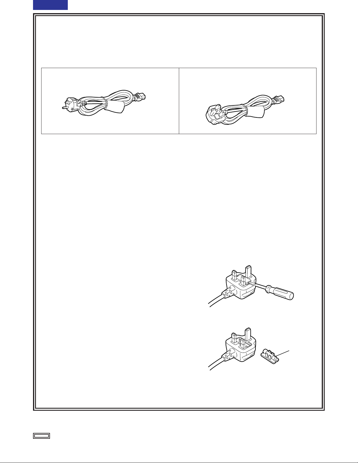
This product is equipped with 2 types of AC mains cable. One is for continental Europe, etc. and the other one is only
for U.K.
Appropriate mains cable must be used in each local area, since the other type of mains cable is not suitable.
FOR CONTINENTAL EUROPE, ETC.
Not to be used in the U.K.
FOR U.K. ONLY
If the plug supplied is not suitable for your socket
outlet, it should be cut off and appropriate one fitted.
How to replace the fuse
1.Open the fuse compartment with a screwdriver.
2.Replace the fuse.
Fuse
indicates safety information.
3 (E)
CONTENTS
IMPORTANT
“Unauthorized recording of copyrighted
television programmes, video tapes and other
materials may infringe the right of copyright
owners and be contrary to copyright laws.”
Operating precaution
Operation near any appliance which generates
strong magnetic fields may give rise to noise in the
video and audio signals. If this should be the case,
deal with the situation by, for instance, moving the
source of the magnetic fields away from the unit
before operation.
indicates safety information.
$
THIS APPARATUS MUST BE EARTHED
To ensure safe operation the three-pin plug must be
inserted only into a standard three-pin power point
which is effectively earthed through the normal
house-hold wiring.
Extension cords used with the equipment must be
three-core and be correctly wired to provide
connection to earth. Wrongly wired extension cords
are a major cause of fatalities.
The fact that the equipment operates satisfactorily
does not imply that the power point is earthed and
that the installation is completely safe. For your
safety, if in any doubt about the effective earthing of
the power point, consult a qualified electrician.
$
DO NOT REMOVE PANEL COVER BY
UNSCREWING.
To reduce the risk of electric shock, do not remove
cover. No user serviceable parts inside.
Refer servicing to qualified service personnel.
WARNING:
TO REDUCE THE RISK OF FIRE OR SHOCK
HAZARD, KEEP THIS EQUIPMENT AWAY
FROM ALL LIQUIDS-USE AND STORE ONLY
IN LOCATIONS WHICH ARE NOT EXPOSED
TO THE RISK OF DRIPPING OR SPLASHING
LIQUIDS, AND DO NOT PLACE ANY LIQUID
CONTAINERS ON TOP OF THE EQUIPMENT.
CAUTION:
TO REDUCE THE RISK OF FIRE OR SHOCK
HAZARD AND ANNOYING INTERFERENCE,
USE THE RECOMMENDED ACCESSORIES
ONLY.
CAUTION:
TO REDUCE THE RISK OF FIRE OR SHOCK
HAZARD, REFER MOUNTING OF THE
OPTIONAL INTERFACE BOARD TO
AUTHORIZED SERVICE PERSONNEL.
CAUTION:
O
Keep the temperature inside the rack to
between 5°C to 40°C.
O
Bolt the rack securely to the floor so that it
will not topple over when VTR is drawn out.
CAUTION:
Do not install or place this unit in a
bookcase, built-in cabinet or any other
confined space in order to maintain adequate
ventilation. Ensure that curtains and any
other materials do not obstruct the
ventilation to prevent risk of electric shock or
fire hazard due to overheating.
CAUTION:
Even when the Power Switch is in the OFF
position, a small current flows the filter circuit.
CAUTION:
TO REDUCE THE RISK OF FIRE OR SHOCK
HAZARD, REFER CHANGE OF SWITCH
SETTING INSIDE THE UNIT TO QUALIFIED
SERVICE PERSONNEL.
CAUTION:
THE AC OUTLET (MAINS SOCKET) SHALL
BE INSTALLED NEAR THE EQUIPMENT AND
SHALL BE EASILY ACCESSIBLE.
4(E)
TOP MENU
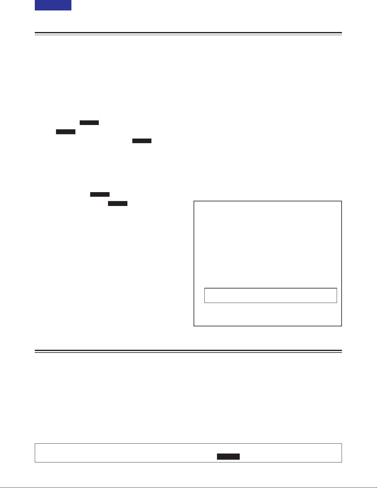
Introduction
The AJ-SD930B and AJ-SD955B are multi-purpose
studio digital VTRs which utilize small, 1/4-inch wide
cassette tapes for high quality recording, playback
and editing of video images recorded at a rate of 50
Mbps in addition to recording, playback and editing in
DVCPRO (25 Mbps) format.
These VTRs incorporate digital compression
technology to dramatically reduce deterioration of
picture quality and sound resulting from dubbing,
thereby attaining high picture quality.
These units also come equipped with a variety of
functions, such as assemble and insert functions,
which are necessary when performing editing
operations with a VTR.
(Editing operations cannot be performed with the AJSD930B alone; however, these operations are
possible if an external controller is connected to the
unit.)
These operating instructions include descriptions for both the AJ-SD955B and AJ-SD930B.
Descriptions which concern only the AJ-SD955B are marked with .
SD955B
Contents
Introduction . . . . . . . . . . . . . . . . . . . . . . . . . . . . . . .4
Features . . . . . . . . . . . . . . . . . . . . . . . . . . . . . . . . . .5
Parts and their functions . . . . . . . . . . . . . . . . . . . .6
Front panel . . . . . . . . . . . . . . . . . . . . . . . . . . . . . . .6
Display panel . . . . . . . . . . . . . . . . . . . . . . . . . . . .12
Rear panel . . . . . . . . . . . . . . . . . . . . . . . . . . . . . .14
Connections . . . . . . . . . . . . . . . . . . . . . . . . . . . . . .16
Tapes . . . . . . . . . . . . . . . . . . . . . . . . . . . . . . . . . . .18
Jog/Shuttle . . . . . . . . . . . . . . . . . . . . . . . . . . . . . . .19
Manual editing . . . . . . . . . . . . . . . . . . . . . .20
Preroll . . . . . . . . . . . . . . . . . . . . . . . . . . . . .20
Automatic editing (deck-to-deck) . . . . . . .21
Switch settings and adjustments . . . . . . . . . . . . .21
Selecting the editing mode . . . . . . . . . . . . . . . . . .22
Registering the edit points . . . . . . . . . . . . . . . . . .22
Checking and previewing edit points . . . . . . . . . .23
Modifying edit points . . . . . . . . . . . . . . . . . . . . . .24
Executing and reviewing automatic editing . . . . .25
Audio split editing . . . . . . . . . . . . . . . . . . .26
Variable memory editing . . . . . . . . . . . . . .28
Setup (initial settings) . . . . . . . . . . . . . . . . . . . . . .29
Setup menus . . . . . . . . . . . . . . . . . . . . . . . . . . . . .30
SYSTEM menu . . . . . . . . . . . . . . . . . . . . . . . . . .33
USER menus . . . . . . . . . . . . . . . . . . . . . . . . . . . .35
<BASIC> . . . . . . . . . . . . . . . . . . . . . . . . . . . . .35
<OPERATION> . . . . . . . . . . . . . . . . . . . . . . . .37
<INTERFACE> . . . . . . . . . . . . . . . . . . . . . . . .40
<EDIT> . . . . . . . . . . . . . . . . . . . . . . . . . . . . . .41
<TAPE PROTECT> . . . . . . . . . . . . . . . . . . . . .43
<TIME CODE> . . . . . . . . . . . . . . . . . . . . . . . .44
<VIDEO> . . . . . . . . . . . . . . . . . . . . . . . . . . . . .46
<AUDIO> . . . . . . . . . . . . . . . . . . . . . . . . . . . . .50
<V BLANK> . . . . . . . . . . . . . . . . . . . . . . . . . . .53
<MENU> . . . . . . . . . . . . . . . . . . . . . . . . . . . . .56
SD955B
SD955B
SD955B
SD955B
SD955B
Time code/user’s bit . . . . . . . . . . . . . . . . . . . . . . .57
Superimpose screen . . . . . . . . . . . . . . . . . . . . . . .59
Video output signals and servo reference
signal . . . . . . . . . . . . . . . . . . . . . . . . . . . . . . . . . . .60
Audio V fade function . . . . . . . . . . . . . . . . . . . . . .62
Audio recording channel and monitor output
selection . . . . . . . . . . . . . . . . . . . . . . . . . . . . . . . . .63
Printed circuit board . . . . . . . . . . . . . . . . . . . . . . .63
Rack mounting . . . . . . . . . . . . . . . . . . . . . . . . . . . .64
Video head cleaning . . . . . . . . . . . . . . . . . . . . . . .65
Condensation . . . . . . . . . . . . . . . . . . . . . . . . . . . . .65
Maintenance . . . . . . . . . . . . . . . . . . . . . . . . . . . . . .65
Error messages . . . . . . . . . . . . . . . . . . . . . . . . . . .66
RS-232C interface . . . . . . . . . . . . . . . . . . . . . . . . .71
SDTI interface . . . . . . . . . . . . . . . . . . . . . . . . . . . . .76
Connector signals . . . . . . . . . . . . . . . . . . . . . . . . .77
Specifications . . . . . . . . . . . . . . . . . . . . . . . . . . . .79
Optional interface boards
O Analog Video Input Board
AJ-YA932G (625i), AJ-YA931G (525i)
O SDTI Interface Board
AJ-YAC930G
O Digital Video Interface Board (IEEE 1394)
AJ-YAD955G
Use only the optional boards listed above.
The AJ-YAD455P or AJ-YAD755G cannot be
used with this unit.
Never use the AJ-YAD455P or AJ-YAD755G with
this unit as it will cause malfunctioning.
AJ-YAD455P: IEEE 1394 board for the AJ-D455
AJ-YAD755G: IEEE 1394 board for the AJ-SD755

5 (E)
CONTENTS
Features
Time codes
This unit has a built-in TCG (time code
generator)/TCR (time code reader).
In addition to the internal time code, external time
code input or input signal VITC can be recorded on
this VTR as the time code.
Multifunctional interface
O Serial digital input/output
A component serial interface is provided as
standard and enables interfacing of the serial digital
component signals.
O Analogue video input/output
Both composite and component signal outputs are
provided as standard.
Use of an analogue video input board (AJ-YA932G,
optional accessory) enables interfacing of the
component (Y, PB, PR) and composite signal input.
O AES/EBU audio input/output
Digital audio input/output connectors are provided.
O IEEE1394 digital input/output
Use of an digital video interface board (AJYAD955G, optional accessory) enables input/output
interfacing of the digital signals with the IEEE1394
standard.
O SDTI input/output
Use of an SDTI board (AJ-YAC930G, optional
accessory) enables input/output interfacing of the
SDTI (Serial Data Transport Interface) signals.
O 9-pin RS-422A/RS-232C remote
In addition to the standard 9-pin serial remote (RS422A), RS-232C and 25-pin parallel remote
connectors are also provided.
The RS-422A enables another VTR to be operated
in parallel with the unit if loop connection is used.
O 4-channel, high-sound-quality digital audio
The 4-channel PCM audio enables independent
editing for all four channels in addition to channel
mixing.
O Menu-based setup
The setup settings, which are conducted prior to
operating the unit, are performed while viewing the
setup menus on the unit’s display or a TV monitor.
Use the AJ-YA931G analog video input board
when the AJ-SD955B is to be used with a 525i
system.
Light and compact
This unit is a 4U size digital VTR and can be easily
mounted in a 19-inch rack by using the rack mounting
adapters (AJ-MA75P, optional accessory).
Up to 92 minutes of recording
M cassettes (max. 33 minutes: using the AJ-5P33MP)
and L cassettes (max. 92 minutes: using the AJ5P92LP) can be used with this unit. Tape width is a
compact 1/4-inch.
Superior picture quality
Superior picture quality is achieved through 4:2:2
component signal recording at 2 times the recording
rate of the existing DVCPRO (25 Mbps) format.
Switching between 525i and 625i TV systems
By selecting the setting (setup menu item No. 070)
that matches the video input signal TV system (525i or
625i), the signals of each TV system can be recorded
and/or played back.
SDI interface
A 4:2:2 serial digital interface is a standard feature.
Compatibility with DVCPRO (25 Mbps) format
This unit can record, play back and edit material in the
existing DVCPRO (25 Mbps) format.
Compatibility with general consumer video
equipment
DV cassette tapes containing material shot with a
consumer digital camera or the like can be played
back on this unit. A cassette adapter (AJ-CS455P) is
necessary when a mini DV cassette tape is to be
used.
Digital slow motion/jog dial
Panasonic’s original digital slow-motion technology
makes it possible to attain clear pictures even during
slow playback at speeds of –0.43 to +0.43/+0.5/+0.75.
(DVCPRO, DVCPRO50)
Dial shuttle
Colour images can be played back in forward and
reverse directions up to a maximum of a32 normal
playback speed.
Recording and playback of UMID information
Recording and playback of UMID (Unique Material
Identifier) information complies with the SMPTE 330M
standard.
UMID information can be checked on the DIAG menu.
UMID information cannot be played back correctly by VTRs that
do not support the recording and playback of UMID information.
In addition, even if a VTR that does not support the recording
and playback of UMID information is connected to this unit and
recording performed, UMID information will not be recorded
correctly.
SD955B
6(E)
CONTENTS
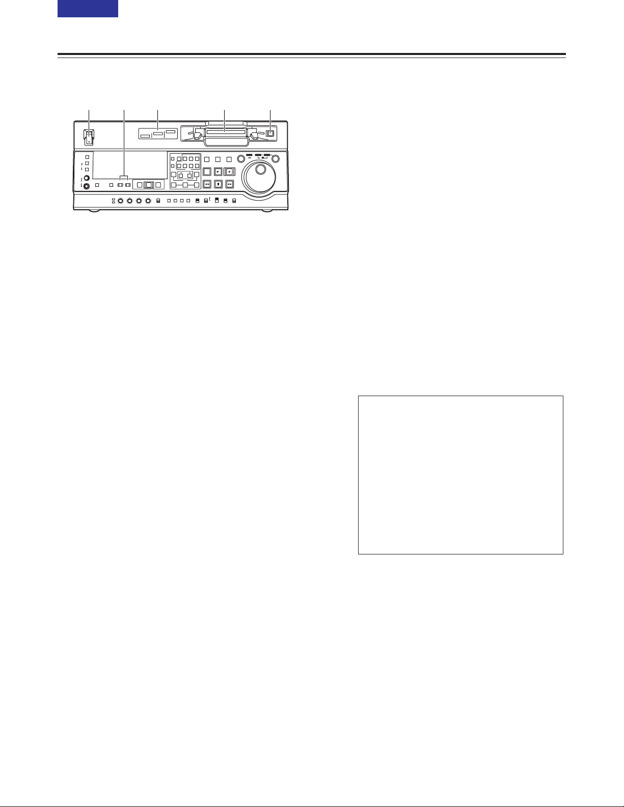
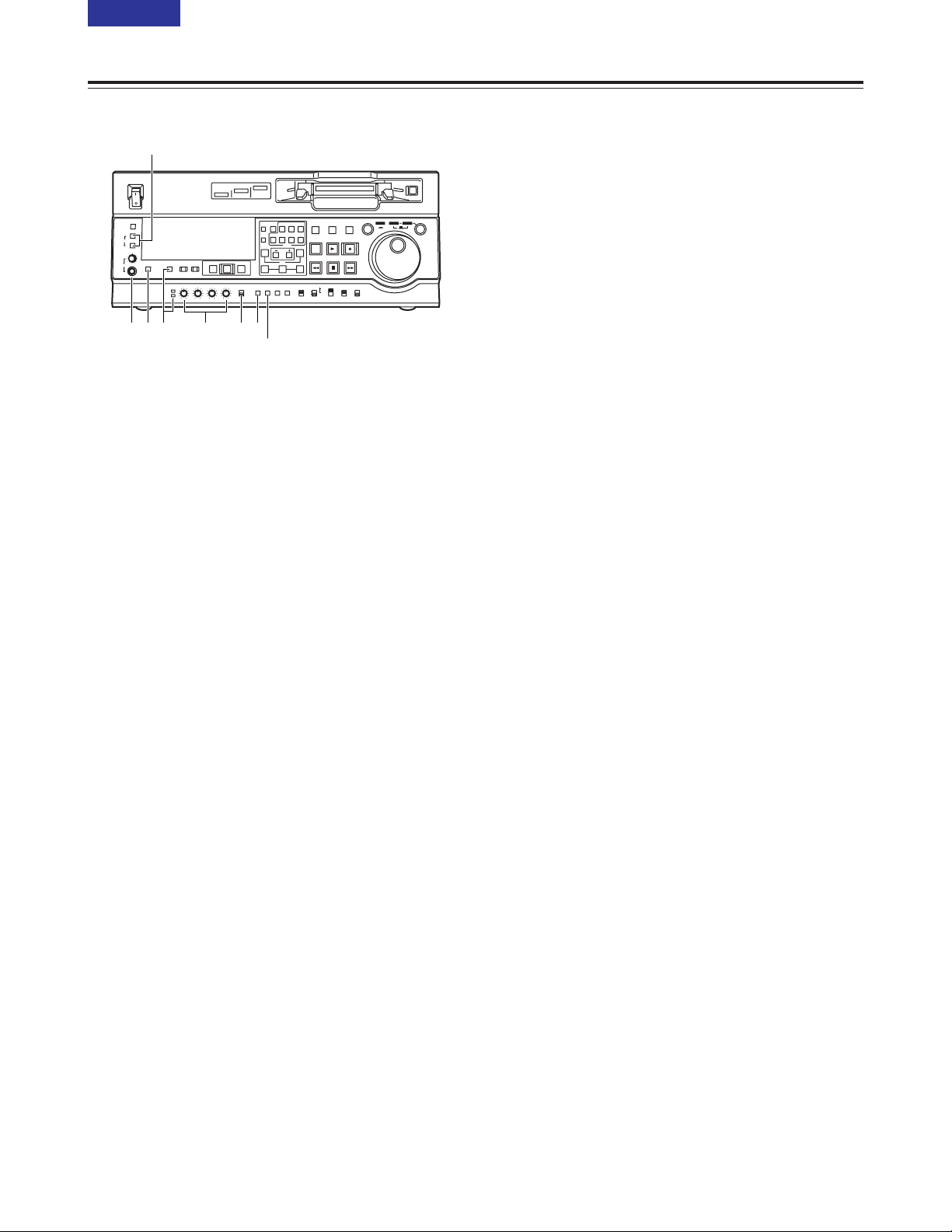
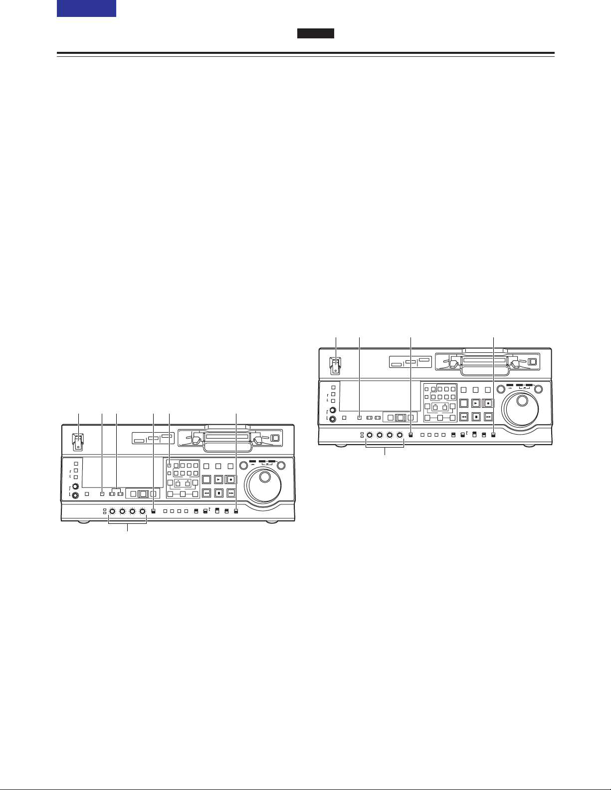
Front panel
1 POWER switch
2 Format display area
The recording format and the format of the tape
inserted in the unit are displayed here.
DVCPRO50:
This indicates recording and playback of
DVCPRO50 (50 Mbps) format tapes.
DVCPRO:
This indicates recording and playback of
DVCPRO (25 Mbps) format tapes.
DV:
This indicates playback of DV format tapes.
3 Cassette insertion slot
4 EJECT button
When this button is pressed, the tape is unloaded
and the cassette is ejected automatically a few
seconds later.
When CTL display has been selected for the
counter display, the display is reset.
EJECT button operation can be enabled or disabled
with setup menu No. 115 (EJECT SW INH).
5 INPUT SELECT buttons
These buttons switch the video and audio input
signals. It is also possible to switch the input signals
to the internal reference signal selected on setup
menu No. 600 (INT SG).
VIDEO:
Each time the VIDEO button is pressed, the input
video signal selection is switched in the order of
Y PB PR 5 CMPST 5 SDI 5 SDTI/1394 5 SG
(SG/SG1/SG2).
O When SG has been selected, the signal is
switched to the internal reference signal
selected on setup menu No. 600 (INT SG).
AUDIO:
Each time the AUDIO button is pressed, the
input audio signal selection is switched in the
order of ANALOG 5 AES/EBU 5 USER SET 5
SDI 5 SDTI/1394 5 SG.
O USER SET is a function which enables the
input signals to be selected and recorded
separately on PCM audio signal channels 1
through 4, and is used in conjunction with the
setup menu.
Example:
<Notes>
O It is possible to inhibit input switching operations
(video and audio) of the INPUT SELECT buttons
with setup menu No. 112 (V IN SEL INH) and
No. 113 (A IN SEL INH).
O Y PB PR, CMPST and SDTI/1394 cannot be
selected unless one of the optional boards (AJYA932G, AJ-YAC930G) has been installed.
Settings
AUDIO button
USER SET
Setup menus
No.715 (CH1 IN SEL) : ANA
No.716 (CH2 IN SEL) : DIGI
No.717 (CH3 IN SEL) : DIGI
No.718 (CH4 IN SEL) : ANA
No.719 (D IN SEL12) : AES
No.720 (D IN SEL34) : SIF
PCM audio signals to be recorded on the tape
CH1 : Analogue input signals
CH2 : AES/EBU digital signals
CH3 : SDI input digital signals
CH4 : Analogue input signals
Parts and their functions
ON
OFF
POWER
DV
DVCPRO
DVCPRO 50
METER
L
R
FULL/FINE
MONITOR SELECT
HEADPHONES
MONITOR
MIX
A VOL
SELECT
INPUT SELECT
PREVIEW/PREVIEW
AUTO EDIT
PREROLL
VIDEO
REC LEVEL
CH1
PB LEVEL
AUDIO
CH2 CH3 CH4
TC
PRESET
MENU SET DIAG
SUPER REC INH
INT TCG
MODE
CONTROL
ON
OFF
UNITY
VAR
COUNTER
RESET
A IN
TRIM
SET
OUTIN
A OUT
CH1 CH4CH2
INSERT
CH3
ASSEM
VIDEO CUE TC
STAND BY
EDIT
REW STOP
PLAY REC
PLAYER
RECORDER
FF
JOG SHTL SLOW
TAPE
EE
ON
REGEN
PRESET
EXIT
OFF
REMOTE
LOCAL
1 2 3 45
7 (E)
CONTENTS
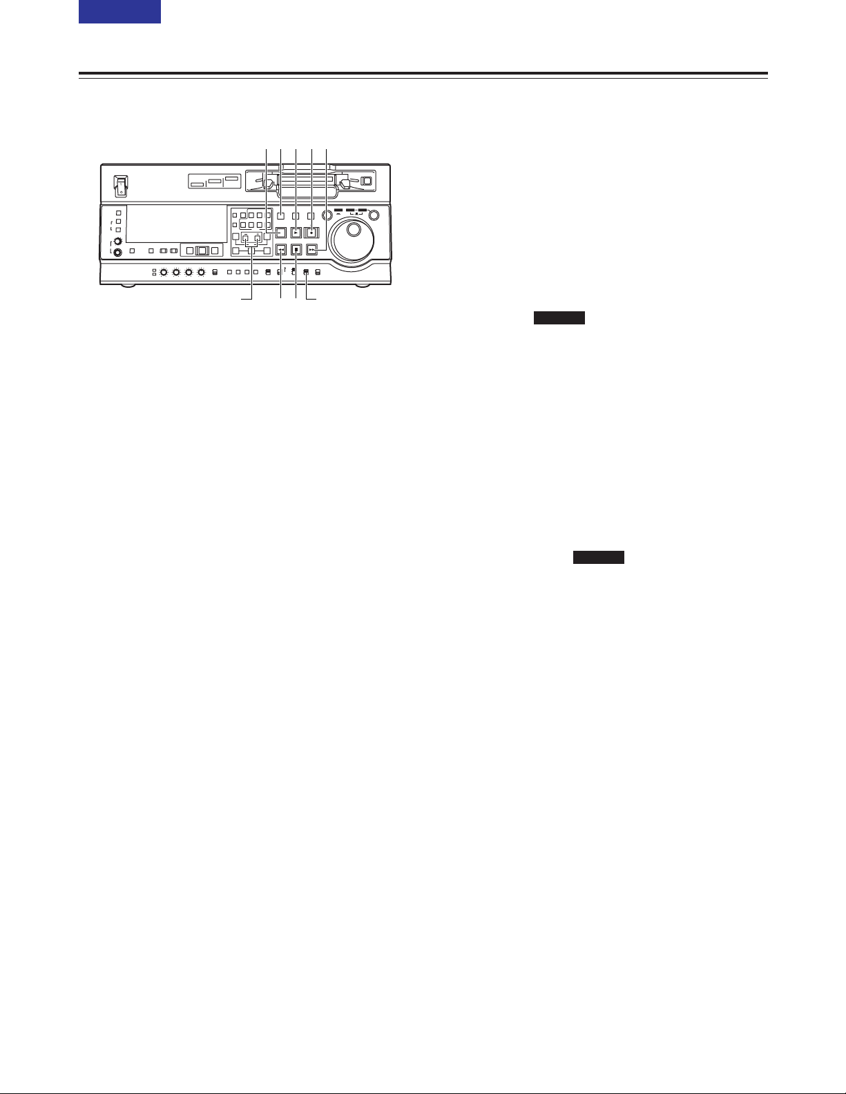
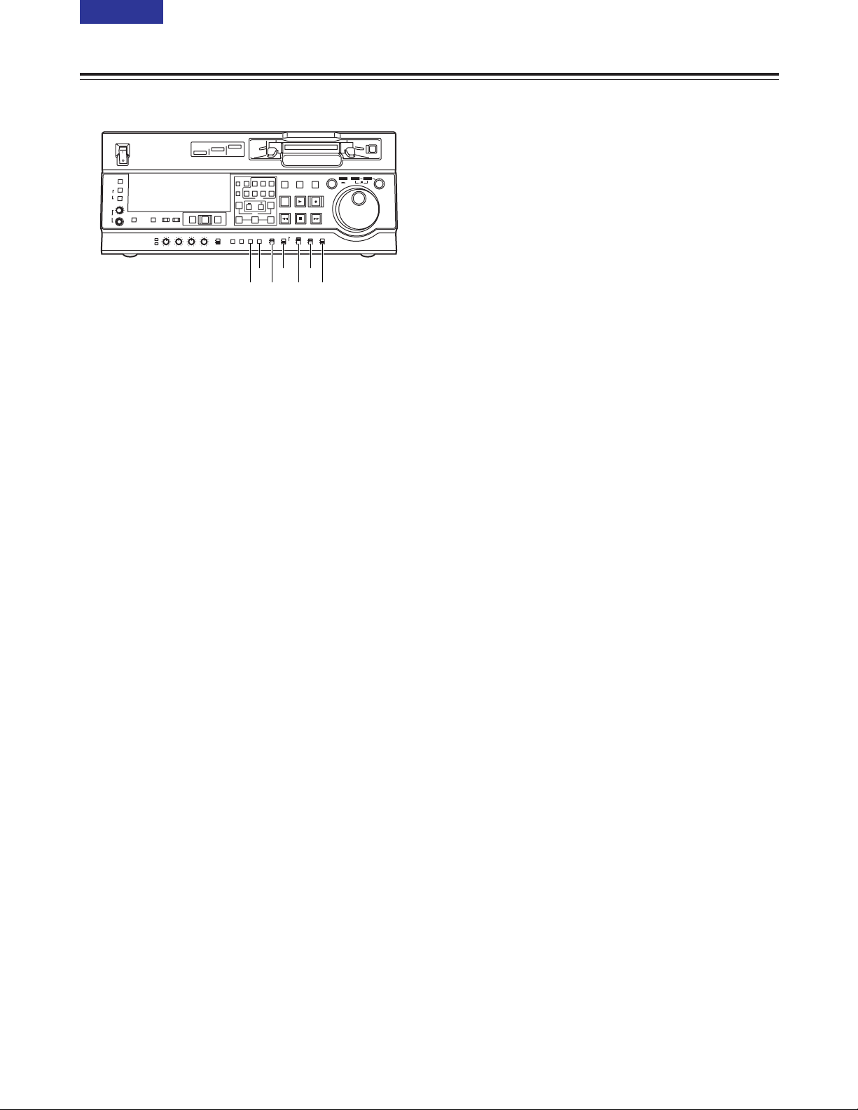
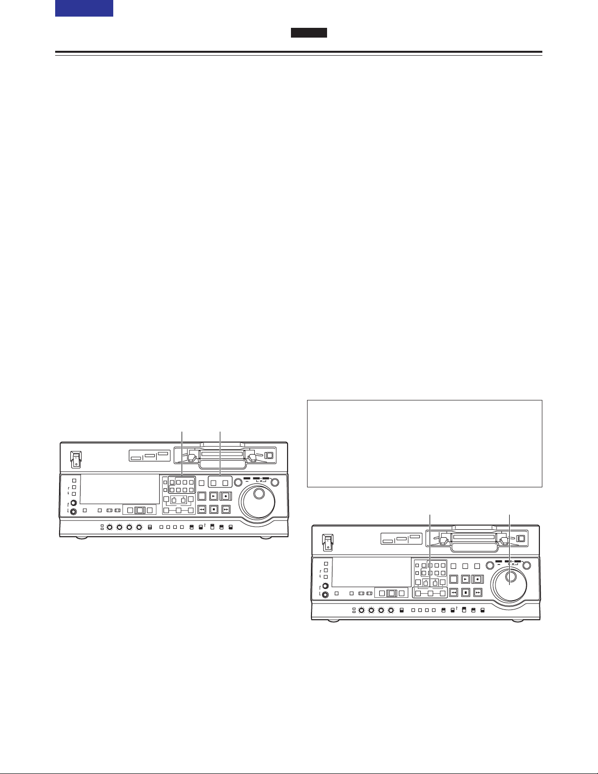
Front panel
6 PLAY button
Press this button to start playback.
When this button is pressed together with the REC
button, recording starts.
On the AJ-SD955B, when this button is pressed
together with the EDIT button during playback, manual
editing starts. However, manual editing will not be
initiated if the servo is not locked. When only the
PLAY button is pressed during manual editing, editing
is exited, and the playback mode is established.
When the TRIM+ (or TRIM–) button is pressed while
this button is held down, playback speed will be
increased (or decreased) by the frame mode unit
selected for the setup menu No. 108 (CAP. LOCK)
setting each time one of the TRIM buttons is pressed.
<Note>
The servo lamp turns off while the speed is being
increased or decreased. At this time, nise occur in the
playback audio signal.
7 REC button
When this button is pressed together with the PLAY
button, recording starts.
When it is pressed during playback, a search, fast
forwarding or rewinding, the E-E mode pictures and
audio signals can be monitored while it is held down.
When it is pressed in the stop mode, the E-E mode
pictures and audio signals can be monitored. When
the STOP button is pressed, the original pictures and
sound are restored.
8 STOP button
When this button is pressed, the tape stops travelling,
and if the MODE switch is set to TAPE, still pictures
can be monitored. Even in the stop mode, the drum
continues to rotate, and the tape remains tightly
wound around the drum.
When the VTR is left in the stop mode beyond a
specific period of time (which can be selected using
setup menu No. 400 to 403), it is automatically set to
the standby OFF mode or STEP FWD mode in order
to protect the tape. The VTR is set to the stop mode
immediately after the cassette has been inserted.
Parts and their functions
9 FF button
When this button is pressed, the tape is fast
forwarded.
The fast forwarding speed can be selected using
setup menu No.102 (FF. REW MAX).
: REW button
When this button is pressed, the tape is rewound.
The rewinding speed can be selected using setup
menu No.102 (FF. REW MAX).
; EDIT button
This button is pressed together with the PLAY button
during playback to initiate manual editing.
When it is pressed during playback, a search, fast
forwarding or rewinding, the input signals in the mode
selected by the ASSEM button or INSERT button can
be monitored in the E-E mode while the button is held
down.
When the button is pressed in the stop mode, the
input signals in the mode selected by the ASSEM
button or INSERT button can be monitored in the E-E
mode.
When the STOP button is pressed, the original
pictures and sound are restored.
< STAND BY button
In the standby ON mode, this button’s lamp lights to
indicate that the same tape tension is applied as in the
regular stop mode and that the head drum is rotating.
In the standby OFF mode, the half loading mode is
established by this button.
When the button is pressed in the stop mode, the
standby OFF mode is established. At this time, its
lamp goes off.
When the VTR is left in the stop mode beyond a
specific period of time, it is automatically set to the
standby OFF mode in order to protect the tape.
When this button or the STOP button is pressed in the
standby OFF mode, the VTR is set to the standby ON
mode.
When a button other than the STOP button is pressed,
the VTR is set to the mode that corresponds to the
button pressed. The time taken by the VTR to transfer
to the standby OFF mode can be selected using setup
menu No. 400 (STILL TIMER).
SD955B
SD955B
ON
OFF
POWER
DV
DVCPRO
DVCPRO 50
METER
L
R
FULL/FINE
MONITOR SELECT
HEADPHONES
MONITOR
MIX
A VOL
SELECT
INPUT SELECT
PREVIEW/PREVIEW
AUTO EDIT
PREROLL
VIDEO
REC LEVEL
CH1
PB LEVEL
AUDIO
CH2 CH3 CH4
TC
PRESET
MENU SET DIAG
SUPER REC INH
INT TCG
MODE
CONTROL
ON
OFF
UNITY
VAR
COUNTER
RESET
A IN
TRIM
SET
OUTIN
A OUT
CH1 CH4CH2
INSERT
CH3
ASSEM
VIDEO CUE TC
STAND BY
EDIT
REW STOP
PLAY REC
PLAYER
RECORDER
FF
JOG SHTL SLOW
TAPE
EE
ON
REGEN
PRESET
EXIT
OFF
REMOTE
LOCAL
6<; 97
8:
TRIM button MODE switch
8(E)
CONTENTS
Front panel
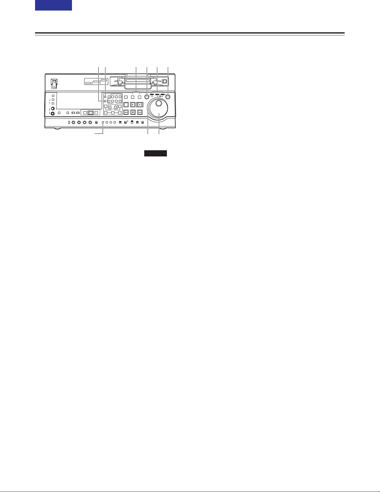
= PLAYER and RECORDER buttons
These buttons are operated if the VTR is to be used
as a recorder to conduct editing operations with a
VTR equipped with an RS-422A serial interface
remote control connector (9 pins). Neither button
works when the VTR is used on its own.
PLAYER:
When this button is pressed, its lamp lights to
indicate that the player connected to the VTR
can be operated by remote control. The VTR’s
editing and tape transport system buttons can
now be used to control the player.
RECORDER:
When this button is pressed, its lamp lights to
indicate that the editing and tape transport
system buttons can now be used to operate the
recorder (this VTR).
When the PLAYER button or RECORDER button is
pressed while ENA has been selected as the setup
menu No. 200 (PARA RUN) setting, the lamps of
both buttons light to indicate that the VTR now
serves as the master unit for parallel run
operations.
(However, when this setting is used, it is no longer
possible to perform external control from the 9-pin
REMOTE connector.)
> Search button
When this button is pressed, the search mode is
established.
When it is pressed after the search dial has been
set to the shuttle mode and turned to the desired
position, playback starts at the speed which was set
by the search dial.
? SHTL/SLOW button
This button is used to select whether the search
dial is to be used for SHTL or SLOW applications.
Each time it is pressed, the search dial is set
alternately to SHTL or SLOW.
SD955B
Parts and their functions
@ Search dial
This dial is used to locate the edit points.
Each time it is pressed, it is set alternatively to the
SHTL/SLOW mode or the JOG mode, and the JOG,
SHTL or SLOW lamp lights.
When the power is turned on, the search dial will not
operate unless it is first returned to the STILL position.
SHTL (shuttle) mode:
When the dial is turned and set to the desired
position while the SHTL lamp among the JOG,
SHTL and SLOW lamps is lit, the tape can be
played at the speed corresponding to the angle at
which the dial has been turned. A still picture
appears when the dial is set to the centre position.
SLOW mode:
When the dial is turned all the way in the
counterclockwise direction while the SLOW lamp
among the JOG, SHTL and SLOW lamps is lit, the
tape speed is set to –4.1a. Similarly, when it is set
to the centre position, it is set to still picture, and
when it is turned all the way in the clockwise
direction, it is set to +4.1a. The SLOW speed in
each direction can be selected using setup menu
No. 320 (VAR FWD MAX) and No. 321 (VAR REV
MAX).
JOG mode:
In this mode, the click-stop positions of the dial are
released, and the tape is played at a speed ranging
from –1a to +1a in accordance with the speed at
which the dial is turned.
The maximum speed can be set using setup menu
No. 323 (JOG FWD MAX) and No. 324 (JOG REV
MAX).
A Dial ring
The dial ring lights during search mode.
The conditions under which the ring is to light can be
selected using setup menu No. 117 (DIAL LAMP).
B JOG, SHTL and SLOW lamps
These lamps indicate the search dial mode.
JOG : This lights in the JOG mode.
SHTL : This lights in the SHTL mode.
SLOW : This lights in the SLOW mode.
C COUNTER button
Each time this button is pressed, the counter display
on the display panel changes to the next setting in the
following sequence: CTL 5 TC 5 UB.
D RESET button
When this button is pressed in the CTL mode, the
counter display is reset to [00:00:00:00]. At the same
time, any edit points that have been registered will
also be cleared.
When this button is pressed while the TC PRESET
button is held down in the TC or UB mode, the time
code generator is reset.
ON
OFF
POWER
DV
DVCPRO
DVCPRO 50
METER
L
R
FULL/FINE
MONITOR SELECT
HEADPHONES
MONITOR
MIX
A VOL
SELECT
INPUT SELECT
PREVIEW/PREVIEW
AUTO EDIT
PREROLL
VIDEO
REC LEVEL
CH1
PB LEVEL
AUDIO
CH2 CH3 CH4
TC
PRESET
MENU SET DIAG
SUPER REC INH
INT TCG
MODE
CONTROL
ON
OFF
UNITY
VAR
COUNTER
RESET
A IN
TRIM
SET
OUTIN
A OUT
CH1 CH4CH2
INSERT
CH3
ASSEM
VIDEO CUE TC
STAND BY
EDIT
REW STOP
PLAY REC
PLAYER
RECORDER
FF
JOG SHTL SLOW
TAPE
EE
ON
REGEN
PRESET
EXIT
OFF
REMOTE
LOCAL
CD > ?
@A
= B
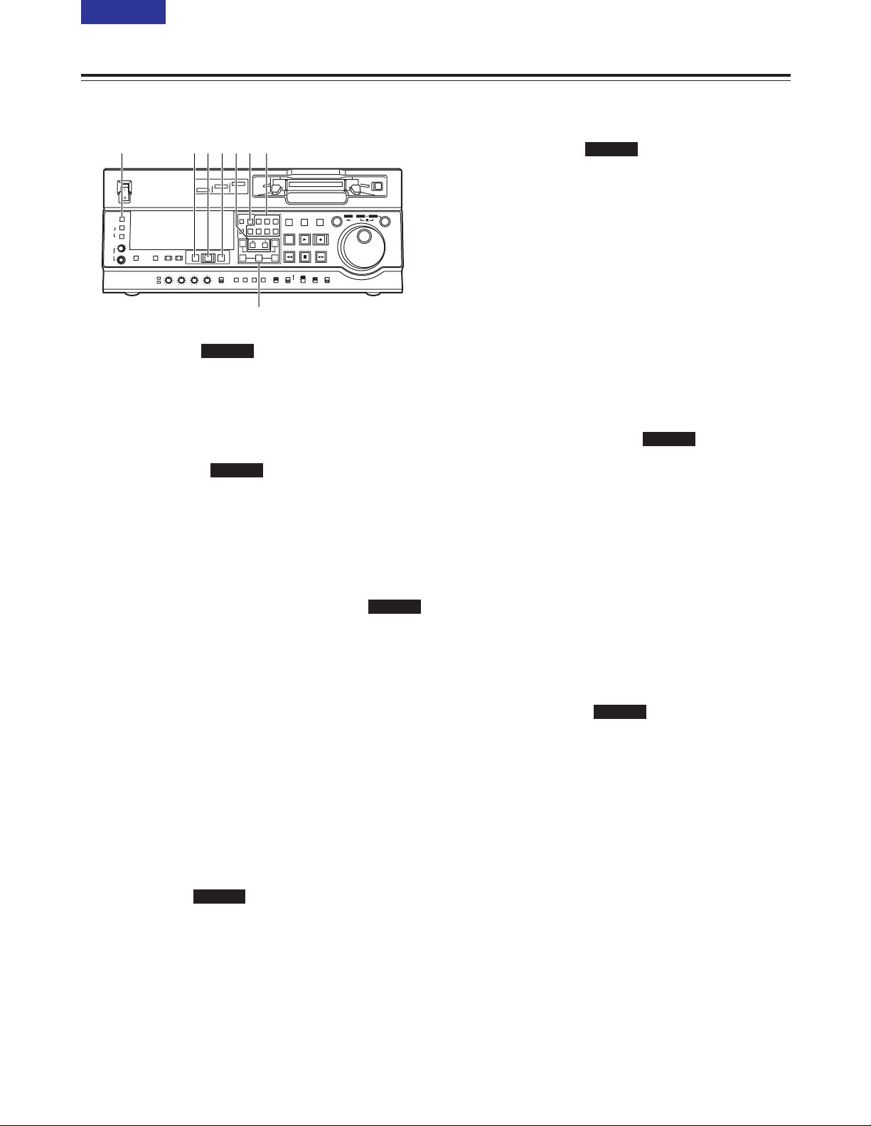
TC PRESET button
9 (E)
CONTENTS
Front panel
E ASSEM button
This button is pressed to proceed with assemble
editing.
It has a self-illuminating lamp which comes ON
when the button is pressed and goes OFF when it
is pressed again.
F INSERT buttons
The input signals to be edited when insert editing is
to be conducted are selected by pressing one of
these seven buttons.
Each of these buttons has a self-illuminating lamp
which comes ON when the button is pressed and
goes OFF when it is pressed again.
G
IN (A IN), SET and OUT (A OUT) buttons
When the SET button is pressed while the IN (A IN)
or OUT (A OUT) button is held down, the IN (A IN)
or OUT (A OUT) point is registered.
The A IN and A OUT buttons are used during audio
split editing to register audio IN and OUT points that
differ from the corresponding video points.
When an IN (A IN) or OUT (A OUT) point has been
registered, the lamp of the IN (A IN) or OUT (A
OUT) button which has registered that point lights.
When these buttons are pressed after points have
been registered, the IN (A IN) or OUT (A OUT)
point value appears on the counter display. When
the IN (A IN) or OUT (A OUT) button is pressed
together with the RESET button, the registration of
the IN (A IN) or OUT (A OUT) point is cleared.
H TRIM buttons
These buttons are used to make fine adjustments
to the IN (A IN) or OUT (A OUT) point.
By pressing the + or – button while the IN (A IN)
button or OUT (A OUT) button is held down, the
registered edit point can be adjusted in 1-frame
increments. When the + button is pressed, the point
is moved ahead by one frame; conversely, when
the – button is pressed, it is moved back by one
frame.
SD955B
SD955B
SD955B
SD955B
Parts and their functions
I PREROLL button
This button is used to locate where a transmission
or manual editing starts on the tape.
When it is pressed, the tape travels to the preroll
point and stops.
The preroll time can be set using setup menu No.
000 (P-ROLL TIME).
When the button is pressed while the IN (A IN) or
OUT (A OUT) button is held down, the tape is cued
up to the registered point concerned.
If this button is pressed when no IN point has been
entered, the point where the button was pressed
will automatically be entered as the IN point.
(However, this is only the case if ENA has been
selected as the setup menu No. 313 (AUTO
ENTRY) setting.
J PREVIEW/REVIEW button
PREVIEW:
When the button is pressed after an edit point
has been registered, the tape travels and the
editing can be previewed without actually
performing the editing.
If the button is pressed when no IN point has
been registered, the point where it was pressed
is registered as the IN point, and preview is
executed using this IN point.
REVIEW:
When the button is pressed after a section has
been edited, the section that was just edited is
played back and can be viewed on the recorder’s
monitor.
K AUTO EDIT button
When this button is pressed after the edit points
have been registered, automatic editing is initiated.
If this button is pressed when no IN point has been
entered, automatic editing is initiated with the point
where the button was pressed serving as the IN
point.
L METER (FULL/FINE) selector button
This button is used to select the scale display for
the audio level meter.
FULL mode:
The standard scale (–∞to 0 dB) is selected.
FINE mode:
The scale in 0.5 dB increments is selected.
The 5position indicates the standard audio
level of –18 dB, and each of the dots (O)
displayed indicates a 1 dB scale increment.
(See page 13)
SD955B
SD955B
SD955B
ON
OFF
POWER
DV
DVCPRO
DVCPRO 50
METER
L
R
FULL/FINE
MONITOR SELECT
HEADPHONES
MONITOR
MIX
A VOL
SELECT
INPUT SELECT
PREVIEW/PREVIEW
AUTO EDIT
PREROLL
VIDEO
REC LEVEL
CH1
PB LEVEL
AUDIO
CH2 CH3 CH4
TC
PRESET
MENU SET DIAG
SUPER REC INH
INT TCG
MODE
CONTROL
ON
OFF
UNITY
VAR
COUNTER
RESET
A IN
TRIM
SET
OUTIN
A OUT
CH1 CH4CH2
INSERT
CH3
ASSEM
VIDEO CUE TC
STAND BY
EDIT
REW STOP
PLAY REC
PLAYER
RECORDER
FF
JOG SHTL SLOW
TAPE
EE
ON
REGEN
PRESET
EXIT
OFF
REMOTE
LOCAL
EIKJ FH
G
L
10 (E)
CONTENTS
Front panel
M MONITOR SELECT (L andR) buttons
These buttons are used to select the audio signals
which are to be output to the MONITOR L and R
connectors.
Each time the L button is pressed, the signal to be
output to the MONITOR L connector is changed in the
following sequence: CH1 5 CH2 5 CH3 5 CH4 5
CUE.
Similarly, each time the R button is pressed, the signal
to be output to the MONITOR R connector is changed
in the following sequence: CH1 5 CH2 5 CH3 5
CH4 5 CUE.
Which signal has now been selected is displayed by
the lighting of the L or R lamps on the level meter
display.
When AUTO has been selected as the setup menu
No. 721 (MONI CH SEL) setting, the display is
switched in tandem with the monitor output. The
channel to which monitor output is to be switched
automatically can be selected using setup menu No.
735 (MON AUTO SEL).
N MONITOR MIX button
This button is used to select the mixed signals which
are to be output to the MONITOR L and R connectors.
Each time the MONITOR SELECT L button is pressed
while this button is held down, the signals to be output
to the MONITOR L connector change in the following
sequence: CH1 + CH2 5 CH3 + CH4 5 CH1 + CH3
5 CH2 + CH4 5 mixing release.
The mixed signals to be output to the MONITOR R
connector are changed in the same way by the
MONITOR SELECT R button.
O Headphone jack and volume control
When stereo headphones are connected to the
headphone jack, the sound during recording, playback
or editing can be monitored using the headphones.
The volume level of the headphone output and
monitor output can be adjusted using the volume
control.
Whether the volume level of the monitor output is to
be coupled to the volume control or not can be
selected using the setup menu item No. 713 (MONI
OUT). (Note that the volume level of the headphones
is coupled at all times.)
When the volume of the monitor output is not coupled,
it is fixed at a set level and is not affected by the
position of the volume control.
Parts and their functions
P A VOL SELECT button and lamps
(REC LEVEL, PB LEVEL)
This switches the function of the audio level control
knobs Q between recording and playback.
Each time this button is pressed (for 1 second or
longer), the functioning of the audio level control
knobs switches alternately been recording and
playback.
When the audio level control knobs Q have been set
to adjust the recording level, the REC LEVEL lamp
lights.
When they have been set to adjust the playback level,
the PB LEVEL lamp lights.
Q Audio level control knobs
These knobs are used to adjust the recording and
playback level of the PCM audio signals (CH1, CH2,
CH3 and CH4).
Whether the recording level or the playback level is to
be adjusted is selected using the A VOL SELECT
button P.
R Audio level control selector switch
UNITY:
At this position, the audio signals are recorded or
played back at a fixed level regardless of the
positions of the audio level control knobs Q.
VAR:
At this position, the audio signals are recorded or
played back at the level adjusted by the audio level
control knobs Q.
<Note>
It is not possible to set it so that both the recording
level and playback level can be adjusted.
When REC LEVEL is selected, UNITY (fixed level) is
set for the playback level; when PB LEVEL is
selected, UNITY is set for the recording level.
S TC PRESET button
This button is used to set the TC or UB value.
When the TC or UB value is to be set, this button is
pressed first to stop the data from advancing. The set
of digits whose display is flashing is then changed.
T MENU button
When this button is pressed, the setup menus are
displayed on the TV monitor (but only when the
VIDEO OUT 3 connector or SDI OUT 3 connector is
used), and the setup menu numbers appear on the
VTR’s display panel.
When it is pressed again, the setup menu settings are
exited, and the original status is restored.
ON
OFF
POWER
DV
DVCPRO
DVCPRO 50
METER
L
R
FULL/FINE
MONITOR SELECT
HEADPHONES
MONITOR
MIX
A VOL
SELECT
INPUT SELECT
PREVIEW/PREVIEW
AUTO EDIT
PREROLL
VIDEO
REC LEVEL
CH1
PB LEVEL
AUDIO
CH2 CH3 CH4
TC
PRESET
MENU SET DIAG
SUPER REC INH
INT TCG
MODE
CONTROL
ON
OFF
UNITY
VAR
COUNTER
RESET
A IN
TRIM
SET
OUTIN
A OUT
CH1 CH4CH2
INSERT
CH3
ASSEM
VIDEO CUE TC
STAND BY
EDIT
REW STOP
PLAY REC
PLAYER
RECORDER
FF
JOG SHTL SLOW
TAPE
EE
ON
REGEN
PRESET
EXIT
OFF
REMOTE
LOCAL
O N P R S
T
M
Q
Front panel
U SET button
When this button is pressed, the data which has been
set using the setup menus is entered.
After the data has been entered, the setup menu
settings are exited, and the original status is restored.
When the internal time code has been set, the data
which has been set is entered.
V DIAG button
When this button is pressed, the VTR information is
displayed.
When it is pressed again, the original display is
restored.
The VTR information consists of the “WARNING”
information, “HOURS METER” information and
“UMID” information.
Switching between the display of each type of
information is accomplished by pressing the search
button.
Displayed on the “WARNING” screen are details of the
warnings.
Displayed on the “HOURS METER” screen are the
deck’s serial number, power-on time, drum rotation
time, tape travel time, number of times a cassette has
been loaded, number of times the power has been
turned on and off, and so on.
Displayed on the “UMID INFO” screen are details of
the UMID (Unique Material Identifier) information.
W SUPER switch
ON:
The superimposed time code and other information
is output to the VIDEO OUT 3 connector or SDI
OUT 3 connector.
OFF:
The superimposed information is not output.
X REC INH switch
This switch is used to enable or disable recording on
the cassette tape.
ON:
Recording on the cassette tape is disabled
(inhibited).
In this state, the REC INH lamp lights on the display
panel.
OFF:
Recording on the cassette tape is enabled so long
as the accidental erasure prevention mechanism on
the cassette tape is set to enable recording.
Parts and their functions
Y TCG switch
REGEN:
The internal time code generator is synchronized
with the time code which the time code reader
has read from the tape.
The signal that is to be used for regeneration is
selected using setup menu No. 503 (TCG
REGEN).
PRESET:
The time code generator can be preset on the
operation panel or by remote control.
EXT:
The external time code which is input from the
time code input connector or video signal VITC is
used. Which of the two is to be set is selected
using setup menu No. 505 (EXT TC SEL).
Z MODE switch
<In the stop mode>
TAPE:
The signal which is played back from the tape is
output.
EE:
The input signal selected by the INPUT SELECT
button is output.
<During recording or editing>
TAPE:
The simultaneous playback signals are output.
(The setup menu No.310 (CONFI EDIT) setting
is necessary.)
EE:
The input signal selected by the INPUT SELECT
button is output.
[ CONTROL switch
This switch is set to the REMOTE or LOCAL
position when the VTR is to be controlled by an
external unit using the REMOTE, RS-232C or
PARALLEL connector.
REMOTE:
Set the switch to this position to control the VTR
using a component that has been connected
using the 9-pin REMOTE, RS-232C or
PARALLEL connector.
LOCAL:
Set the switch to this position to control the VTR
using its operation panel.
When the unit is to be controlled with the switch
at this position by a component connected using
the PARALLEL connector, selection can be
made using setup menu No. 211 (LOCAL 25P).
11 (E)
CONTENTS
ON
OFF
POWER
DV
DVCPRO
DVCPRO 50
METER
L
R
FULL/FINE
MONITOR SELECT
HEADPHONES
MONITOR
MIX
A VOL
SELECT
INPUT SELECT
PREVIEW/PREVIEW
AUTO EDIT
PREROLL
VIDEO
REC LEVEL
CH1
PB LEVEL
AUDIO
CH2 CH3 CH4
TC
PRESET
MENU SET DIAG
SUPER REC INH
INT TCG
MODE
CONTROL
ON
OFF
UNITY
VAR
COUNTER
RESET
A IN
TRIM
SET
OUTIN
A OUT
CH1 CH4CH2
INSERT
CH3
ASSEM
VIDEO CUE TC
STAND BY
EDIT
REW STOP
PLAY REC
PLAYER
RECORDER
FF
JOG SHTL SLOW
TAPE
EE
ON
REGEN
PRESET
EXIT
OFF
REMOTE
LOCAL
WU Y [
V X Z
12 (E)
CONTENTS
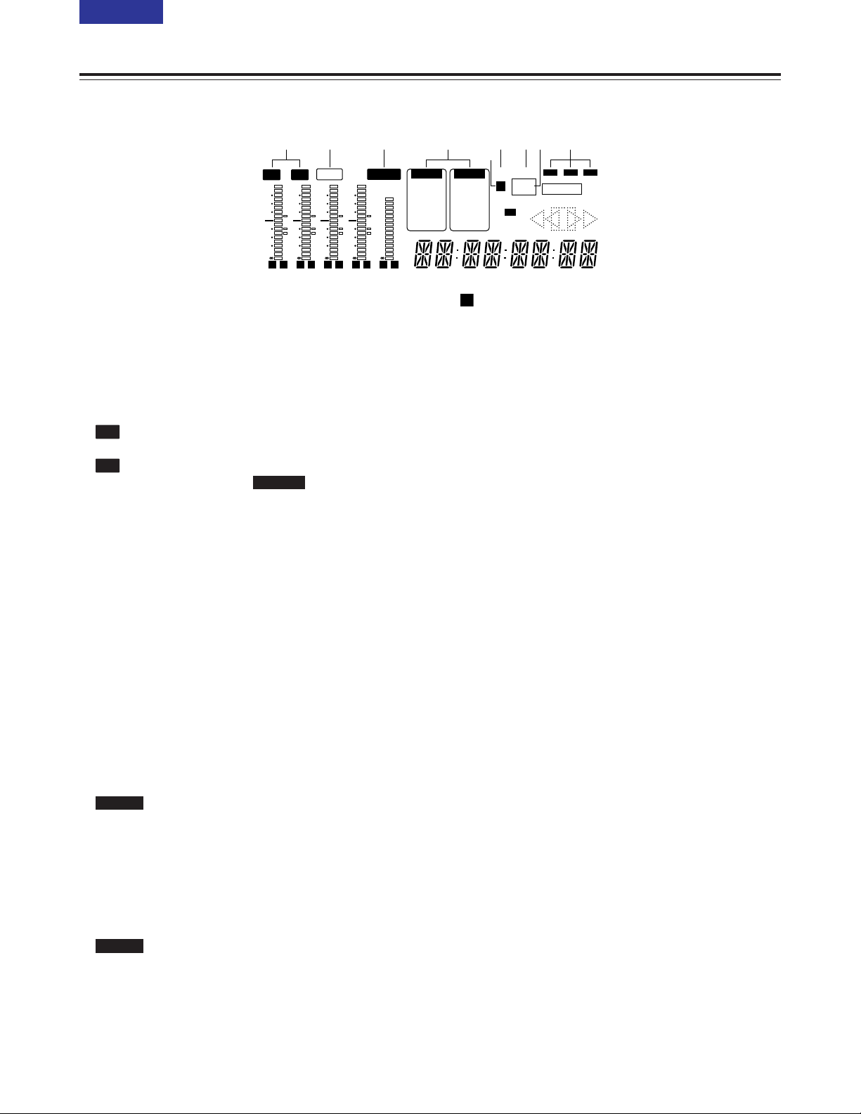
Display panel
1 TV system displays
The selected TV system is displayed here.
With the AJ-SD955B, it is possible to switch
between the 525 interlace and 625 interlace
systems by setting setup menu item No. 070 (TV
SYSTEM).
With the AJ-SD930B, only the 625 interlace TV
system can be used.
: This lights when the 625 interlaced TV system
is selected.
: This lights when the 525 interlaced TV system
has been selected.
2 WIDE lamp
This lamp lights when 16:9 wide-screen information
is being recorded on a tape.
Recording of wide-screen information can be
selected on setup menu No. 645 (WIDE SELECT).
This lights lamps during tape playback when widescreen information has been recorded on the tape.
3 REMOTE lamp
This lamp lights when the CONTROL switch has
been set to the REMOTE position.
4 INPUT SELECT display area
The characters corresponding to the selected input
signals light. With all input signals except for
analogue audio signals, the fact that no signals have
been selected is indicated by a flashing display.
Y PB PR :
Analogue component video signals
(option)
CMPST :
Analogue composite video signals
(option)
SDI :
Serial digital video signals
SDTI/1394 :
Compressed digital signals (option)
SG/SG 1/SG 2:
Internal reference signals
ANALOG :
Analogue audio signals
AES/EBU :
Digital audio signals
USER SET :
Recording audio signal selection
SDI :
Serial digital audio signals
SDTI/1394 :
Compressed digital signals (option)
SG :
Internal reference signals
AUDIO
VIDEO
SD955B
525
625
Parts and their functions
5 lamp
This lamp lights when UMID information is present
on the input signal in E-E mode.
This lamp lights during tape playback when UMID
information has been recorded on the tape.
6 SCH lamp
This lamp lights when the SCH phase of the
external synchronized signal (REF VIDEO) is inside
the prescribed range.
At all other times, the lamp is off.
7=lamp
This lamp lights when a cassette tape is inserted
into the VTR.
In the standby OFF mode, this lamp is flashing.
8 SERVO lamp
This lamp lights when the drum servo or capstan
servo locks.
9 Channel condition lamps
These lamps light to indicate the error rate status.
(green 5 white 5 red)
Green:
This lights when the error rates for the video
and audio playback signals are both at
acceptable levels.
White :
This lights when the error rate for the video
or audio playback level has increased.
The playback picture and sound remain
unaffected even while this lamp is lit.
Red :
This lights when the error rate for the video
or audio playback level has increased to the
extent that correction or interpolation was
performed.
U
3 6 85741 92
CTL
ANALOG
AUDIO
U
AES/EBU
USER SET
SDI
SDTI/1394
SG
INH
SCH
DVCPR O
50
DVCAM
SERVO
EDIT REC
TC
UB
=
Y PB PR
VIDEO
CMPST
SDI
SDTI/1394
SG 1 2
REMOTEWIDE
625525
dB
0
-
4
-
8
-
12
-
16
-
20
-
25
-
30
-
L R
dB
0
-
4
-
8
-
12
-
16
-
20
-
25
-
30
-
L R
dB
0
-
4
-
8
-
12
-
16
-
20
-
25
-
30
-
L R
dB
0
-
4
-
8
-
12
-
16
-
20
-
25
-
30
-
L R
dB
CUE
-
8
-
12
-
16
-
20
-
25
-
30
-
L R
13 (E)
CONTENTS
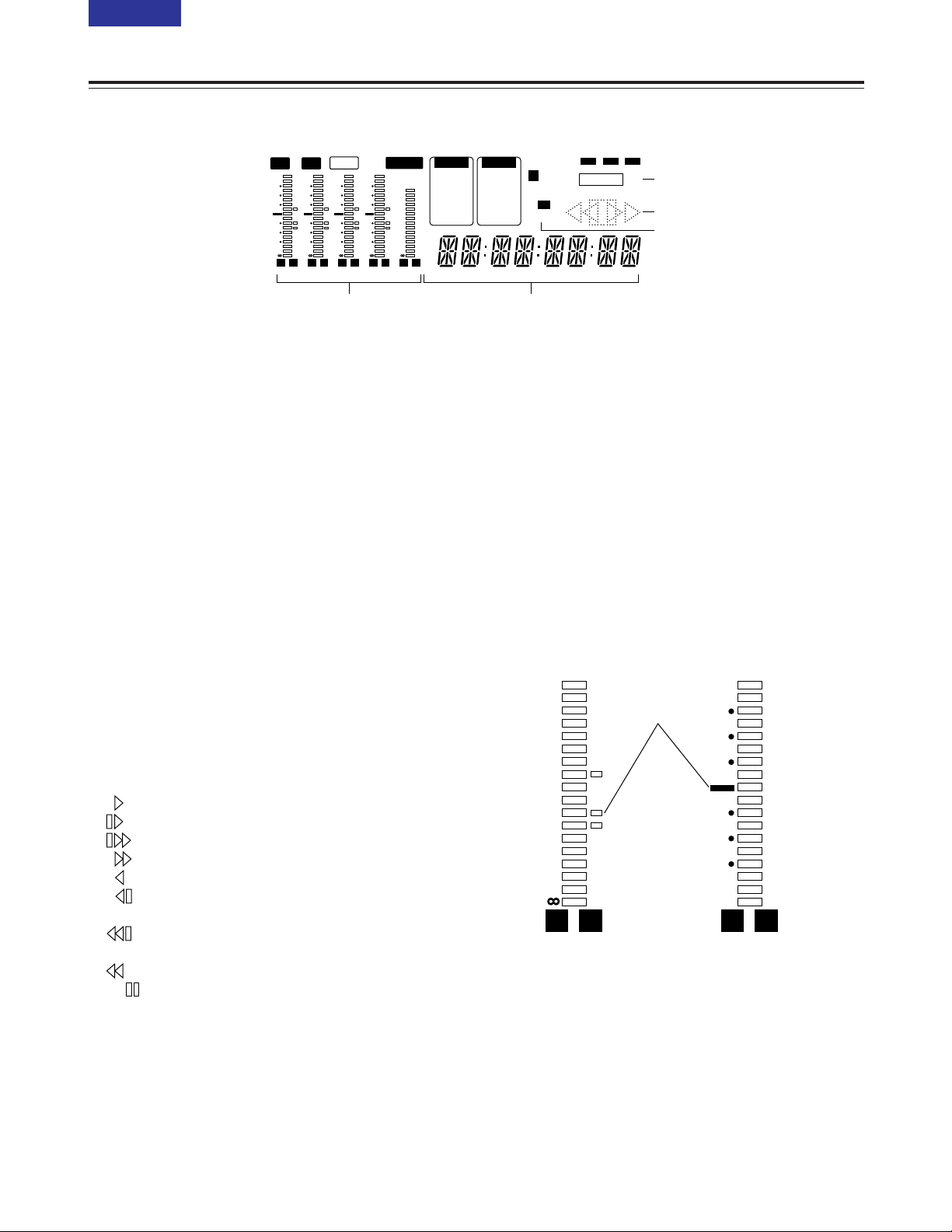
: EDIT, EDIT REC, REC and REC INH lamps
EDIT:
This lights when an editing mode has been
selected.
EDIT REC:
This lights when the edit recording mode has
been established.
REC:
This lights when the recording mode has been
established.
REC INH:
This lights in the recording inhibit status (when
the REC INH switch at the bottom front panel is
set to ON or the cassette is in the accidental
erasure prevention status).
In this status, recording and editing are not
possible.
Whether the REC INH lamp is to light or flash
when recording has been inhibited by the
accidental erasure prevention tab on the
cassette tape can be selected using setup menu
No. 114 (REC INH LAMP).
; Tape transport displays
The tape transport status is displayed here.
: Normal playback or recording
: Playback at a speed slower than 1a
: Playback at a speed faster than 1a
: Fast forwarding (FF)
: Playback in the reverse direction at 1a
: Playback in the reverse direction at a speed
slower than 1a
: Playback in the reverse direction at a speed
faster than 1a
: Rewinding (REW)
: Pause/still
< Format displays
The recording format and the format of the tape
inserted in the unit are displayed here.
= Counter display
The tape counter, time code, etc. are displayed
here.
The type of value displayed is indicated by CTL, TC
or UB.
> Level meters
These meters indicate the levels of the CH1, CH2,
CH3, CH4 and CUE tracks of the PCM audio
signals.
During recording or while E-E is selected, the levels
of the audio input signals appear; during playback,
the levels of the audio output signals appear.
Using the METER selector button L, the audio
level display is switched from the FULL mode to the
FINE mode or vice versa. (See page 9)
Parts and their functions
Display panel
L R
dB
0
-
4
-
8
-
12
-
16
-
20
-
25
-
30
-
L R
Reference level
(–18 dB)
Each of the dots (O) indicates
a 1 dB scale increment.
FULL mode FINE mode
CTL
ANALOG
AUDIO
U
AES/EBU
USER SET
SDI
SDTI/1394
SG
INH
SCH
DVCPRO
50
DVCAM
SERVO
EDIT REC
TC
UB
=
Y PB PR
VIDEO
CMPST
SDI
SDTI/1394
SG 1 2
REMOTEWIDE
625525
dB
0
-
4
-
8
-
12
-
16
-
20
-
25
-
30
-
L R
dB
0
-
4
-
8
-
12
-
16
-
20
-
25
-
30
-
L R
dB
0
-
4
-
8
-
12
-
16
-
20
-
25
-
30
-
L R
dB
0
-
4
-
8
-
12
-
16
-
20
-
25
-
30
-
L R
dB
CUE
-
8
-
12
-
16
-
20
-
25
-
30
-
L R
;
:
<
=>
14 (E)
CONTENTS
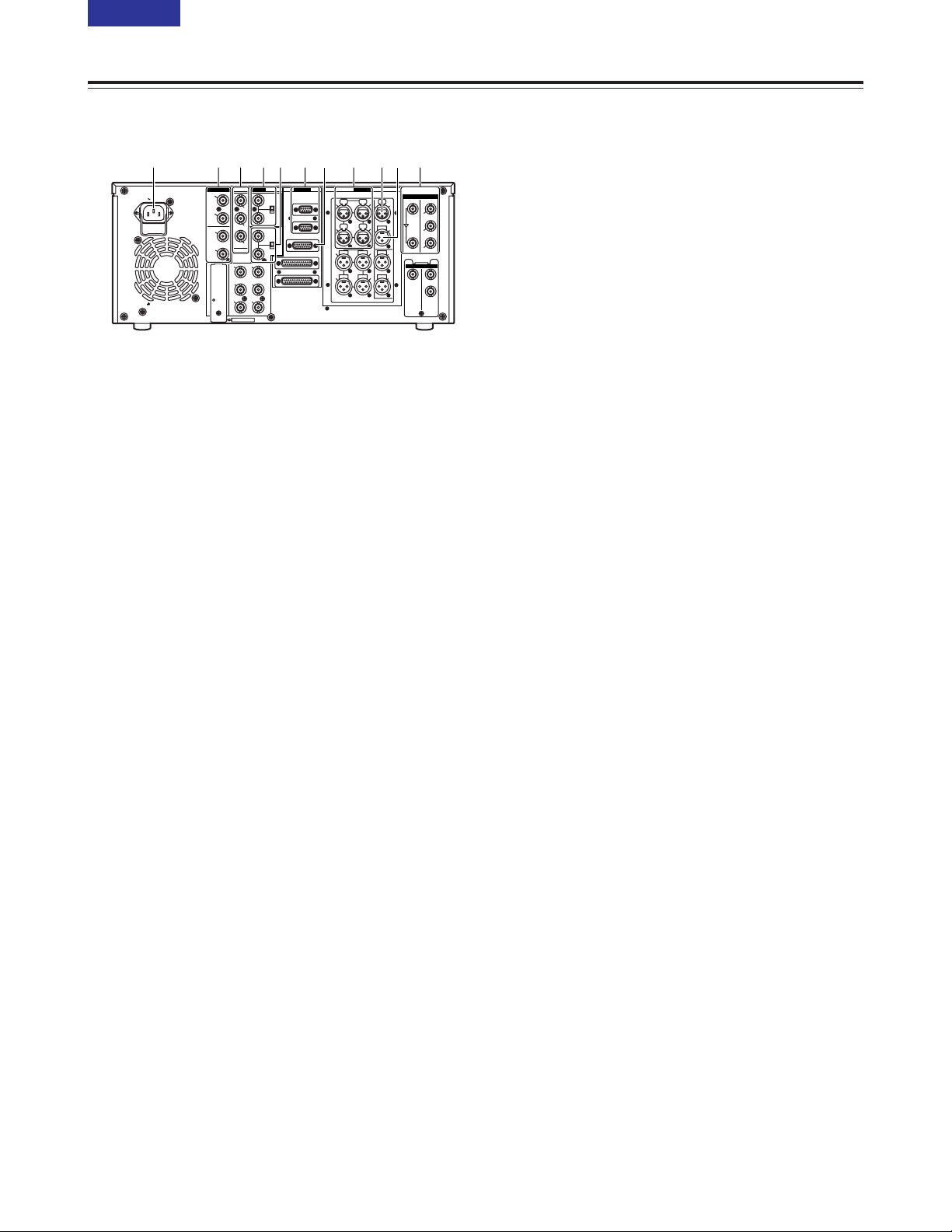
Rear panel
1 AC IN socket
Connect one end of the power cord supplied to this
socket and the other end to the power outlet.
2 DIGITAL AUDIO IN and OUT connectors
These are the input and output connectors for
digital audio signals that comply with the AES/EBU
standards.
<Note>
The digital audio signals which are to be input to
these connectors must be synchronized with the
video input signals. Otherwise, noise will be
generated in the audio output signals.
3 ANALOG COMPONENT VIDEO IN connectors
(optional)
The analogue component video signals are input to
these connectors.
4 ANALOG COMPOSITE VIDEO IN connectors
and 75 Ω termination switch (optional)
The analogue composite video signals are input to
these connectors. A loop-through configuration is
featured for each pair of input connectors.
For termination at this VTR, set the termination
switch to ON.
5 REF VIDEO IN connectors and 75 Ω termination
switch
These are the input connectors of the reference
video signals.
Input a reference signal with colour burst.
For termination at this VTR, set the termination
switch to ON.
<Note>
Video and audio output may be disturbed when the
reference video signal is not input, so it is
recommended that a system which inputs the
reference video signal be used.
Parts and their functions
6 Remote control connectors
These connectors make it possible to use two of
these VTRs or to connect this VTR to an external
controller so that the VTR can be operated from an
external component.
Two remote control connectors are provided: one
for IN/OUT use and the other for OUT use only.
IN/OUT:
For connection with an external controller
For connection with deck-to-deck operations
OUT:
For connection with parallel run operations
For loop-through use
<Note>
If connection is to be made to the OUT connector
for deck-to-deck operations where this VTR will
serve as the recorder, which of the two connectors
is to be used can be selected using setup menu No.
212 (MASTER PORT).
7 ENCODER REMOTE connector
An external encoder remote controller is connected
to this connector when the video output signal
settings are to be adjusted from an external
component.
8 ANALOG AUDIO IN connectors
These are the analogue audio input connectors.
9 TIME CODE IN connector
This connector is used to record an external time
code onto the tape.
: TIME CODE OUT connector
During playback, the playback time code is output
through this connector.
During recording, the time code generated by the
internal time code generator is output.
; SERIAL DIGITAL COMPONENT AUDIO and
VIDEO IN and OUT connectors
These are the input and output connectors for the
digital component audio and video signals that
comply with the ITU-R BT.656-4 standard.
Video signals containing superimposed information
can be output through the SDI OUT 3 connector.
Whether the superimposing is to be set ON or OFF
is selected using the SUPER switch W on the front
panel.
<Note>
The digital audio signals which are to be input to
these connectors must be synchronized with the
video input signals. Otherwise, noise will be
generated in the audio output signals.
PUSH PUSH
PUSH PUSH
PUSH
AC IN
SIGNAL
GND
AES/EBU
SDI
SDTI
ANALOG
CH1/2
IN
Y
VIDEO
VIDEO
OUT
SERVICE ONLY
REMOTE IN/OUT
CH1 CH2AUDIO
IN
ENCODER REMOTE
RS-232C
PARALLEL
REMOTE OUT
IN
REF VIDEO
IN
ON
OFF
P
B
P
R
Y1
2
(WFM)
3
(SUPER)
P
B
P
R
OPTION
CH3/4
IN
CH1/2
OUT
CH3/4
OUT
REMOTE
75Ω
ON
OFF
75Ω
ANALOG
TC
IN
IN
ACTIVE
THROUGH
OUT
1
TC
OUT
MON
L
MON
R
CH4
CH3
CH1 CH2AUDIO
OUT
CH4
CH3
2
OPTION
IN OUT
1
2
3
(SUPER)
1 92 8 ;64 5 7 :3
15 (E)
CONTENTS
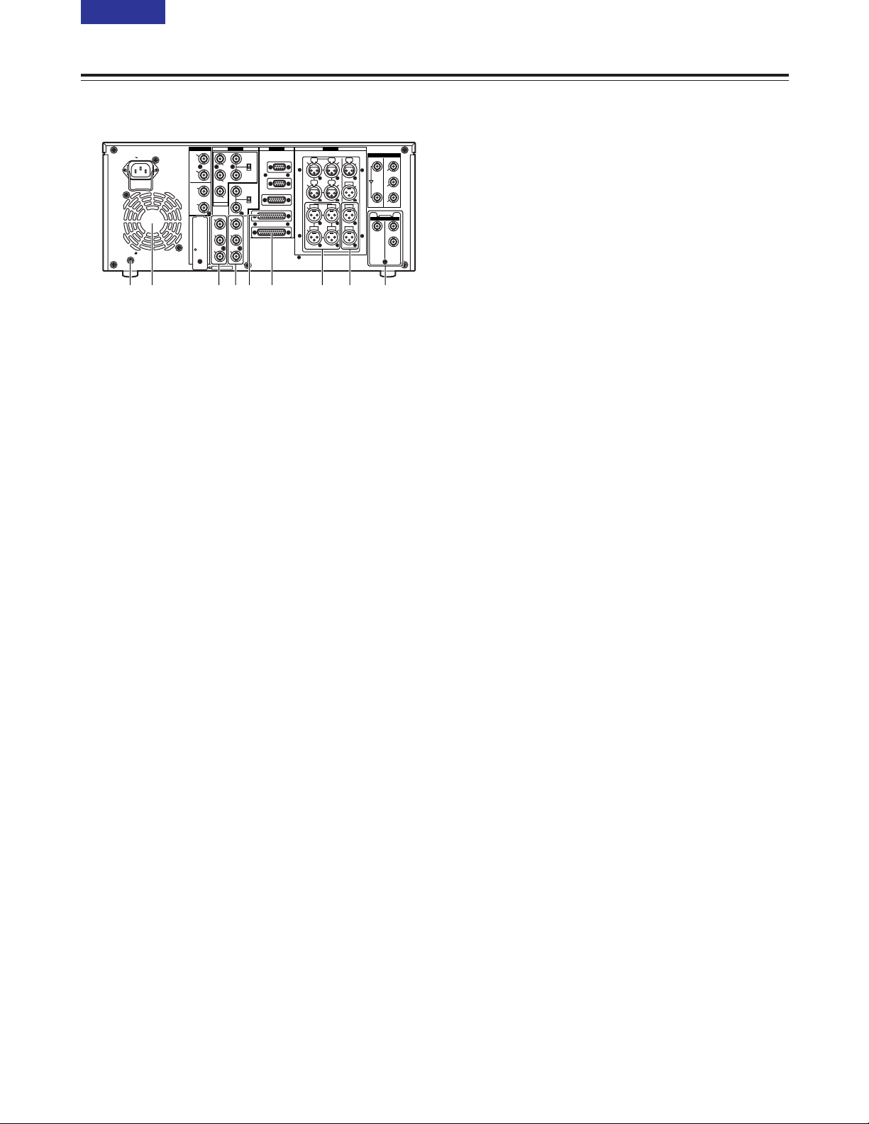
Rear panel
< Fan
This fan is used to cool down the VTR.
If, for any reason, the fan stops, “E-10” will appear
on the counter display.
= SIGNAL GND terminal
This is connected to the signal ground terminal on
the component connected to this VTR in order to
minimize noise. It is not a safety ground.
> ANALOG COMPONENT VIDEO OUT connectors
The analogue component video signals are output
through these connectors.
? ANALOG COMPOSITE VIDEO OUT connectors
The analogue composite video signals are output
through these connectors.
The waveform monitor (WFM) signal can be output
from the VIDEO OUT 2 connector.
It can be selected using setup menu No. 00 (WFM
SEL).
Video signals containing superimposed information
can be output through the VIDEO OUT 3 connector.
Whether the superimposing is to be set ON or OFF
is selected using the SUPER switch W on the front
panel.
@ RS-232C connector
A personal computer or other component can be
connected to this connector to operate the VTR.
Parts and their functions
A PARALLEL REMOTE connector
This connector is used when the VTR is to be
operated by an external component.
B ANALOG AUDIO OUT connectors
The analogue audio signals are output through
these connectors.
C MONITOR OUT connectors
During playback, the PCM audio signals
(CH1/CH2/CH3/CH4) or playback signals from the
CUE track are output through these connectors.
<Note>
Noise may appear on the CUE signal at the instant
recording is started.
D SDTI input and output connectors (optional)
When the SDTI board (AJ-YAC930G, optional
accessory) is installed in this VTR, digital data can
be input and output using the SDTI (Serial Data
Transport Interface) format.
IEEE1394 digital input/output connector
(optional)
Use of an digital video interface board (AJYAD955G, optional accessory) enables input/output
interfacing of the digital signals with the IEEE1394
standard.
PUSH PUSH
PUSH PUSH
PUSH
AC IN
SIGNAL
GND
AES/EBU
SDI
SDTI
ANALOG
CH1/2
IN
Y
VIDEO
VIDEO
OUT
SERVICE ONLY
REMOTE IN/OUT
CH1 CH2AUDIO
IN
ENCODER REMOTE
RS-232C
PARALLEL
REMOTE OUT
IN
REF VIDEO
IN
ON
OFF
P
B
P
R
Y1
2
(WFM)
3
(SUPER)
P
B
P
R
OPTION
CH3/4
IN
CH1/2
OUT
CH3/4
OUT
REMOTE
75Ω
ON
OFF
75Ω
ANALOG
TC
IN
IN
ACTIVE
THROUGH
OUT
1
TC
OUT
MON
L
MON
R
CH4
CH3
CH1 CH2AUDIO
OUT
CH4
CH3
2
OPTION
IN OUT
1
2
3
(SUPER)
< @ A= > ? B DC
16 (E)
CONTENTS
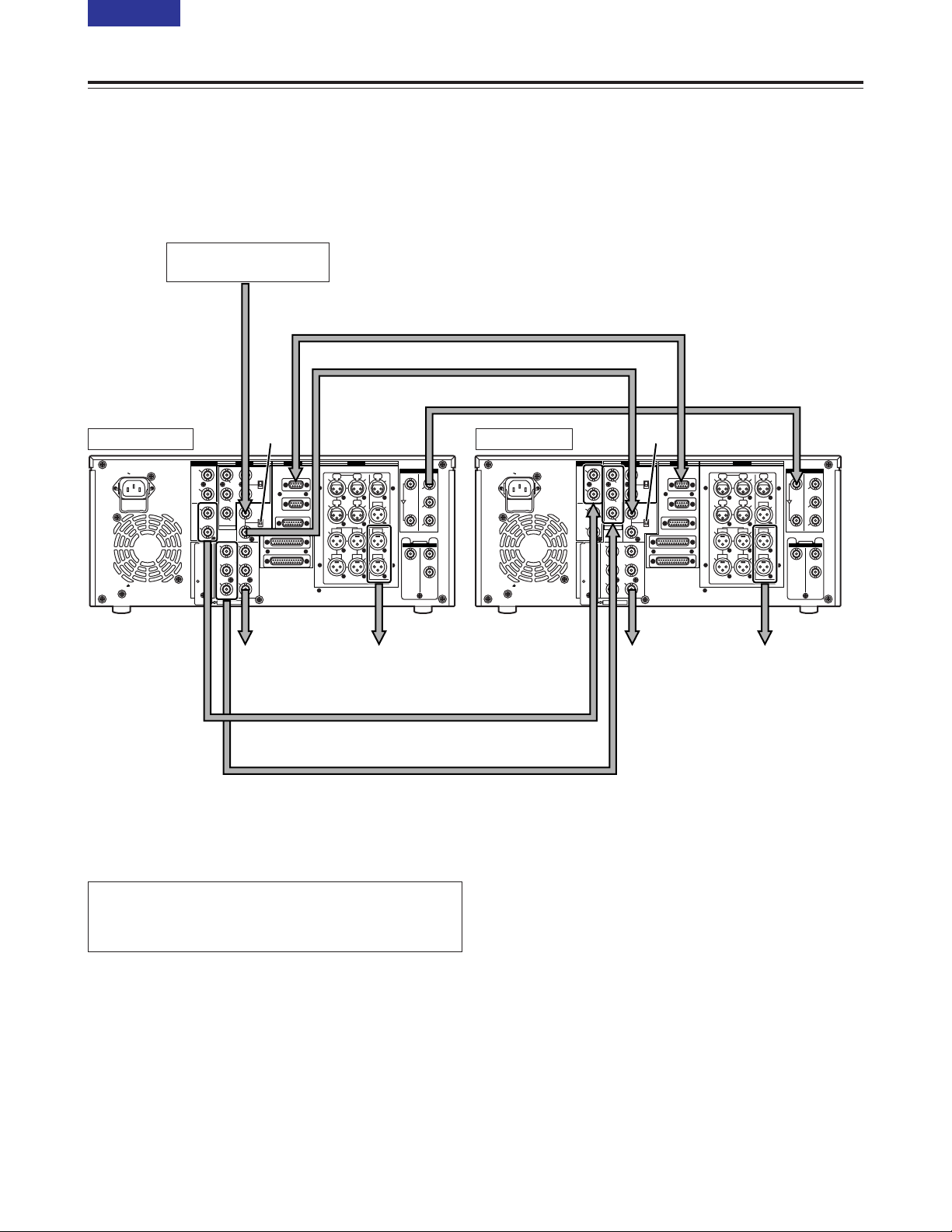
Source machine:
Set the CONTROL switch on the front panel to REMOTE.
Recorder:
Set the CONTROL switch on the front panel to LOCAL.
Connections
Reference signal
generator
Source machine Recorder
To audio
monitor device
To video
monitor device
To video
monitor device
Analogue video signal (component)
OWhen the analogue video input board (option)
has been installed.
Digital audio
Digital video/audio signal
Remote control signal (9 pin)
To audio
monitor device
ON
OFF
<Note>
Video and audio output may be disturbed when the reference
video signal is not input, so it is recommended that a system
which inputs the reference video signal be used.
AES/EBU
CH1/2
AC IN
SIGNAL
GND
IN
CH3/4
IN
CH1/2
OUT
CH3/4
OUT
ANALOG
VIDEO
IN
ON
Y
75Ω
OFF
P
B
REF VIDEO
IN
ON
P
75Ω
R
OPTION
OFF
Y1
VIDEO
OUT
2
P
B
(WFM)
3
P
(SUPER)
R
SERVICE ONLY
REMOTE
REMOTE IN/OUT
REMOTE OUT
ENCODER REMOTE
RS-232C
PARALLEL
ANALOG
PUSH PUSH
CH1 CH2AUDIO
IN
PUSH PUSH
CH3
CH4
CH1 CH2AUDIO
OUT
CH3
CH4
SDI
IN
OUT
TC
PUSH
IN
1
ACTIVE
TC
THROUGH
OUT
2
3
(SUPER)
MON
L
OPTION
SDTI
IN OUT
MON
1
R
2
AC IN
SIGNAL
GND
CH1/2
IN
CH3/4
IN
CH1/2
OUT
CH3/4
OUT
AES/EBU
Y1
P
B
P
R
SERVICE ONLY
ANALOG
VIDEO
IN
ON
Y
75Ω
OFF
P
B
REF VIDEO
IN
ON
P
75Ω
R
OPTION
OFF
VIDEO
OUT
2
(WFM)
3
(SUPER)
REMOTE
REMOTE IN/OUT
REMOTE OUT
ENCODER REMOTE
RS-232C
PARALLEL
ANALOG
PUSH PUSH
CH1 CH2AUDIO
IN
PUSH PUSH
CH3
CH1 CH2AUDIO
OUT
CH3
SDI
IN
OUT
TC
PUSH
IN
1
ACTIVE
TC
THROUGH
CH4
OUT
2
3
(SUPER)
MON
L
OPTION
SDTI
IN OUT
MON
CH4
1
R
2
17 (E)
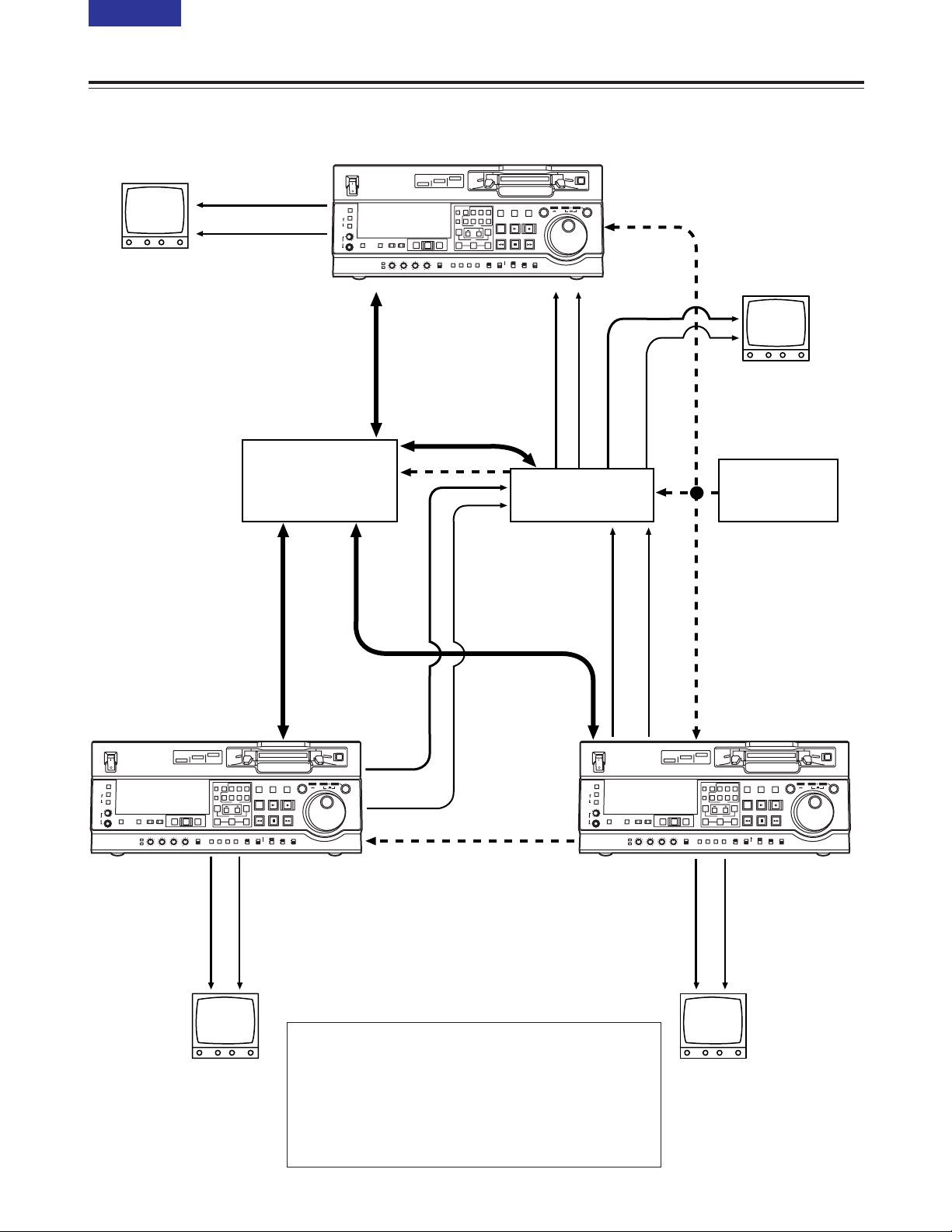
CONTENTS
Connections with editing controller
Connections
AV monitor
AV monitor
AV monitor
Source machine
Source machine
AV monitor
Recorder
Video monitor
signals
Video monitor
signals
Audio monitor
signals
Audio monitor
signals
Audio monitor
signals
Video monitor
signals
Audio monitor
signals
Video monitor
signals
Remote
Remote
Remote
Video input signals
Video output signals
Video output signals
Audio input signals
Audio output
signals
Audio output signals
Reference signal
Reference signal
Editing controller
AV switcher
Reference signal
generator
To REMOTE IN/OUT
connector
To REMOTE IN/OUT
connector
To REMOTE
IN/OUT
connector
<Notes>
OWhen an editing controller made by CMX is used, support must
be provided at the editing controller side.
OIf the remote signal (9 pin) connection is to be disconnected
from one component and connected to another instead,
recheck the editing controller settings, etc.
OVideo and audio output may be disturbed when the reference
video signal is not input, so it is recommended that a system
which inputs the reference video signal be used.
ON
OFF
METER
FULL/FINE
MONITOR SELECT
HEADPHONES
L
R
POWER
A VOL
MONITOR
SELECT
MIX
REC LEVEL
PB LEVEL
DVCPRO 50
DVCPRO
DV
COUNTER
ASSEM
VIDEO CUE TC
RESET
CH1 CH4CH2
CH3
INSERT
A IN
A OUT
INPUT SELECT
VIDEO
CH1
PREVIEW/PREVIEW
AUDIO
CH2 CH3 CH4
AUTO EDIT
TRIM
SET
PREROLL
OUTIN
SUPER REC INH
TC
PRESET
MENU SET DIAG
UNITY
VAR
ON
OFF
OFF
STAND BY
EDIT
REW STOP
INT TCG
REGEN
PRESET
EXIT
JOG SHTL SLOW
RECORDER
PLAYER
PLAY REC
FF
MODE
CONTROL
TAPEEEON
REMOTE
LOCAL
ON
POWER
OFF
METER
FULL/FINE
L
MONITOR SELECT
R
A VOL
MONITOR
INPUT SELECT
PREVIEW/PREVIEW
SELECT
MIX
HEADPHONES
VIDEO
AUDIO
CH1
CH2 CH3 CH4
REC LEVEL
PB LEVEL
DVCPRO 50
DVCPRO
DV
COUNTER
ASSEM
VIDEO CUE TC
RESET
CH1 CH4CH2
CH3
INSERT
A IN
TRIM
PREROLL
TC
PRESET
UNITY
VAR
MENU SET DIAG
SET
OUTIN
ON
OFF
AUTO EDIT
PLAYER
STAND BY
RECORDER
EDIT
PLAY REC
A OUT
FF
REW STOP
SUPER REC INH
INT TCG
MODE
CONTROL
REGEN
TAPEEEON
REMOTE
PRESET
OFF
LOCAL
EXIT
JOG SHTL SLOW
METER
FULL/FINE
MONITOR SELECT
HEADPHONES
ON
POWER
OFF
L
R
A VOL
MONITOR
SELECT
MIX
REC LEVEL
PB LEVEL
DV
INPUT SELECT
PREVIEW/PREVIEW
AUTO EDIT
VIDEO
AUDIO
CH1
CH2 CH3 CH4
DVCPRO 50
DVCPRO
COUNTER
ASSEM
VIDEO CUE TC
RESET
CH1 CH4CH2
INSERT
A IN
TRIM
SET
PREROLL
TC
PRESET
MENU SET DIAG
UNITY
VAR
CH3
OUTIN
PLAYER
STAND BY
RECORDER
EDIT
PLAY REC
A OUT
FF
REW STOP
SUPER REC INH
INT TCG
MODE
CONTROL
REGEN
ON
TAPEEEON
REMOTE
PRESET
OFF
LOCAL
OFF
EXIT
JOG SHTL SLOW
ON
OFF
POWER
DV
DVCPRO
DVCPRO 50
METER
L
R
FULL/FINE
MONITOR SELECT
HEADPHONES
MONITOR
MIX
A VOL
SELECT
INPUT SELECT
PREVIEW/PREVIEW
AUTO EDIT
PREROLL
VIDEO
REC LEVEL
CH1
PB LEVEL
AUDIO
CH2 CH3 CH4
TC
PRESET
MENU SET DIAG
SUPER REC INH
INT TCG
MODE
CONTROL
ON
OFF
UNITY
VAR
COUNTER
RESET
A IN
TRIM
SET
OUTIN
A OUT
CH1 CH4CH2
INSERT
CH3
ASSEM
VIDEO CUE TC
STAND BY
EDIT
REW STOP
PLAY REC
PLAYER
RECORDER
FF
JOG SHTL SLOW
TAPE
EE
ON
REGEN
PRESET
EXIT
OFF
REMOTE
LOCAL
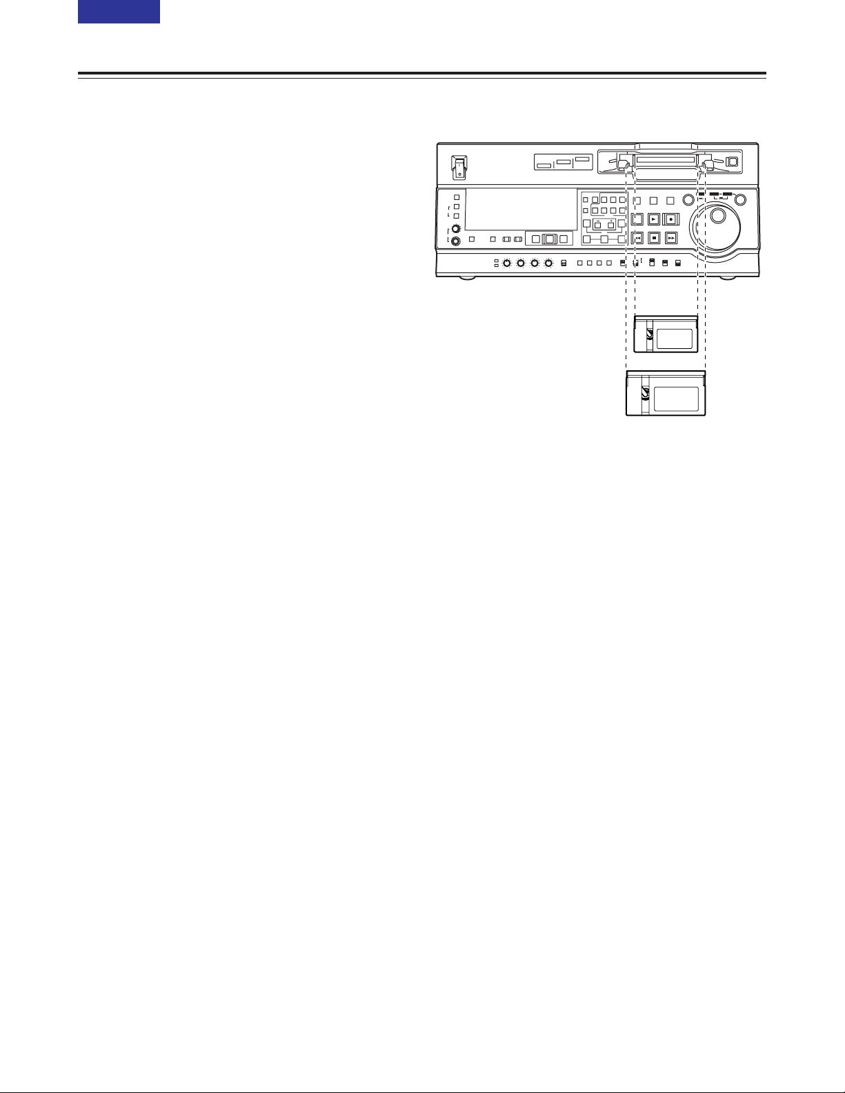
L cassette size
18 (E)
CONTENTS
Consumer-use DV and DVCAM cassettes
(Standard DV and DVCAM cassettes, mini DV and
DVCAM cassettes)
O Use a cassette adapter (AJ-CS455P) when a mini
DV or DVCAM cassette is to be used.
Note that inserting a mini DV or DVCAM cassette
without the use of a cassette adapter will cause
malfunctioning.
Also note that long-duration mini DV cassettes (80
minutes in the standard mode and 120 minutes in
the LP mode) cannot be used.
O It is not possible to play back tapes which have
been recorded in the LP mode.
O When editing material recorded on a consumer-use
DV or DVCAM cassette, first record the material on
a DVCPRO tape or other tape used by VTRs for
broadcast applications.
O The maximum transport speed of a mini DV or
DVCAM cassette tape is 32a.
O The images may be subject to disturbance during
the slow motion playback of consumer-use DV and
DVCAM cassette tapes.
O From the perspective of protecting consumer-use
DV and DVCAM cassette tapes, minimize the
number of times the tapes are cued up at the same
locations as much as possible.
O When consumer-use DV and DVCAM cassette
tapes are used, the maximum time for STILL
TIMER is set to 10 seconds.
It is recommended that tapes bearing the
Panasonic brand be used as the consumer-use DV
tapes.
M cassettes
Tapes capable of up to 33 minutes of recording or
playback
(AJ-5P23MP, AJ-5P33MP)
L cassettes
Tapes capable of up to 92 minutes of recording or
playback
(AJ-5P63LP, AJ-5P92LP)
O Use AJ-5P92LP tapes which have been recorded
using the DVCPRO (25M) format in a VTR that
supports 184 minutes of DVCPRO (25M) format
recording and playback.
M cassette size
Tapes
Align the centre of the cassette with the centre of the
insertion slot, and press it in gently.
The cassette tape will load automatically.

19 (E)
CONTENTS
Jog mode
Jog/Shuttle
1
Press the search dial so that it remains pressed in.
Check that the JOG lamp has lit.
Shuttle mode
1
Press the search dial so that it is released from the
pressed-in position.
The SHTL lamp lights, and the shuttle mode is
established.
O Immediately after the power is turned on, turn
the search dial and leave it at the centre
position.
3
To transfer the VTR from the jog mode to another
mode, press the button that corresponds to the
mode concerned.
2
Turn the search dial.
The dial’s click-stops are released, and the tape is
played back at the speed (–1a to +1a)
corresponding to the speed at which the dial is
turned.
The maximum speed can be switched using setup
menu No. 323 (JOG FWD MAX) and No. 324 (JOG
REV MAX) settings.
However, noise will occur at all speeds other than
–0.43a to +0.43a.
When the dial is no longer turned, the still picture
mode is established.
3
Turn the search dial.
O When the SHTL lamp among the JOG, SHTL
and SLOW lamps is lit, the playback picture
speed changes from 0 up to ±32a depending on
the dial position.
This speed can be switched to ±8.4a, ±16a or
±32a using setup menu No. 101 (SHTL MAX).
The dial has a click-stop at the centre position
where the still picture mode is established.
O When the SLOW lamp among the JOG, SHTL
and SLOW lamps is lit, the playback picture
speed changes from –4.1 up to +4.1a
depending on the dial position.
The maximum speed can be switched using
setup menu No. 320 (VAR FWD MAX) and No.
321 (VAR REV MAX) settings. However, noise
will occur at all speeds other than –0.43a to
+0.43a, +0.5a and +0.75a.
The dial has a click-stop at the centre position
where the still picture mode is established.
4
To transfer the VTR from the shuttle mode to
another mode, press the STOP button or other
button.
2
Press the SHTL/SLOW button and switch to SHTL
or SLOW.
<Note>
The direct search mode in which the VTR is
transferred to the shuttle mode or jog mode by turning
the search dial is set at the factory.
By selecting KEY as the setup menu No. 100
(SEARCH ENA) setting, the VTR can be set to the
mode in which it will not be transferred to the search
mode unless the search button is pressed.
<Notes>
O It is possible to listen to playback audio in the –10
to +10 speed range from the audio monitor output.
(PCM must be selected for the setup menu No. 721
(MONI CH SELECT) setting.)
O The audio playback sound heard in the search
mode contains noise.

20 (E)
CONTENTS
Manual editing
SD955B
1
Select the editing mode.
ASSEMBLE:
Assemble (frame-to-frame continuity) editing is
performed in this mode.
INSERT:
Insert editing is performed in this mode.
2
Select the channels to be edited.
For insert editing, press the buttons corresponding
to the channels to be edited so that their lamps
light.
3
Press the PLAY button.
4
While monitoring the TV monitor, search the
position (IN point) where the editing is to be
started, and press the PLAY and EDIT buttons
together at this position.
5
Similarly, while monitoring the TV monitor, search
the position (OUT point) where the editing is to be
terminated, and press the PLAY or STOP button at
this position.The unit will change to STOP or PLAY
mode and editing will stop.
Preroll
SD955B
1
Press the PREROLL button.
The VTR now performs the preroll operation.
O If the edit IN point has been registered, the tape
is rewound from the edit IN point for the period
of time which was set by setup menu No. 000
(P-ROLL TIME), and it then stops.
O If the edit IN point has not been registered, the
tape is rewound from the position where the
button was pressed for the period of time which
was set by setup menu item No.000 (P-ROLL
TIME), and it then stops.
<Notes>
O The time code or CTL must be continuously
recorded on the tape between the edit IN point and
preroll point.
O When the IN point has not been registered, it is
possible to select whether to register the IN point
and proceed with the preroll or proceed with the
preroll without registering the IN point using setup
menu No. 313 (AUTO ENTRY).
21 (E)
CONTENTS
Automatic editing (deck-to-deck)
SD955B
1
Set the POWER switch to ON.
2
Use the INPUT SELECT buttons to select the
video and audio input signals.
3
Switch the time counter display to TC, CTL or UB.
5
If the recording levels are to be adjusted using the
level controls, set the audio level control selector
switch to the VAR position.
If the recording levels are to be fixed, set the
switch to the UNITY position.
6
Set the CONTROL switch to LOCAL.
Switch settings and adjustments
When using the AJ-SD955B as the recorder
1
Set the POWER switch to ON.
3
If the playback levels are to be adjusted using the
level controls, set the audio level control selector
switch to the VAR position.
If the playback levels are to be fixed, set the switch
to the UNITY position.
4
Set the CONTROL switch to REMOTE.
When using the AJ-SD955B as the player
Audio level control knobs
Audio level control knobs
ON
OFF
POWER
DV
DVCPRO
DVCPRO 50
METER
L
R
FULL/FINE
MONITOR SELECT
HEADPHONES
MONITOR
MIX
A VOL
SELECT
INPUT SELECT
PREVIEW/PREVIEW
AUTO EDIT
PREROLL
VIDEO
REC LEVEL
CH1
PB LEVEL
AUDIO
CH2 CH3 CH4
TC
PRESET
MENU SET DIAG
SUPER REC INH
INT TCG
MODE
CONTROL
ON
OFF
UNITY
VAR
COUNTER
RESET
A IN
TRIM
SET
OUTIN
A OUT
CH1 CH4CH2
INSERT
CH3
ASSEM
VIDEO CUE TC
STAND BY
EDIT
REW STOP
PLAY REC
PLAYER
RECORDER
FF
JOG SHTL SLOW
TAPE
EE
ON
REGEN
PRESET
EXIT
OFF
REMOTE
LOCAL
1 354 62
ON
OFF
POWER
DV
DVCPRO
DVCPRO 50
METER
L
R
FULL/FINE
MONITOR SELECT
HEADPHONES
MONITOR
MIX
A VOL
SELECT
INPUT SELECT
PREVIEW/PREVIEW
AUTO EDIT
PREROLL
VIDEO
REC LEVEL
CH1
PB LEVEL
AUDIO
CH2 CH3 CH4
TC
PRESET
MENU SET DIAG
SUPER REC INH
INT TCG
MODE
CONTROL
ON
OFF
UNITY
VAR
COUNTER
RESET
A IN
TRIM
SET
OUTIN
A OUT
CH1 CH4CH2
INSERT
CH3
ASSEM
VIDEO CUE TC
STAND BY
EDIT
REW STOP
PLAY REC
PLAYER
RECORDER
FF
JOG SHTL SLOW
TAPE
EE
ON
REGEN
PRESET
EXIT
OFF
REMOTE
LOCAL
1 32 4
4
Use the A VOL SELECT button to switch the
function of the audio level control knobs to
recording. (See page 10)
2
Use the A VOL SELECT button to switch the
function of the audio level control knobs to
playback. (See page 10)
22 (E)
CONTENTS
Automatic editing (deck-to-deck)
SD955B
1
Select the editing mode.
For assemble editing, press the ASSEM button.
For insert editing, press the INSERT button.
ASSEM:
This sets the unit to assemble (frame-to-frame
continuity) editing mode.
INSERT:
This sets the unit to insert editing mode.
2
Select the channels to be edited.
With assemble editing, the ASSEM lamp lights.
With insert editing, press the buttons
corresponding to the channels to be edited so that
their lamps light.
3
Select the VTR to be operated.
(Settings for editing using two VTRs)
Press the PLAYER or RECORDER button to select
the VTR which is to be operated.
PLAYER:
Press this button if the player VTR is to be
operated to register the edit points.
RECORDER:
Press this button if the recorder VTR (this unit)
is to be operated to register the edit points.
Selecting the editing mode
1
Locate the edit IN point by performing the jog or
shuttle operation.
Set the tape to the still picture mode at the desired
position.
For a detailed description of the jog and shuttle
operations, refer to page 19.
2
Press the SET button while holding down the IN
button.
The edit IN point is now registered.
The edit IN point value appears on the display
panel.
3
Locate the edit OUT point by performing the jog or
shuttle operation.
Set the tape to the still picture mode at the desired
position.
Registering the edit points
Match frame processing function
When two VTRs are used to perform the editing
operations, there will be a total of 4 edit points: the
IN and OUT points for the player and those for the
recorder. However, the last point is automatically
calculated so only three of the edit points need to be
registered.
ON
OFF
POWER
DV
DVCPRO
DVCPRO 50
METER
L
R
FULL/FINE
MONITOR SELECT
HEADPHONES
MONITOR
MIX
A VOL
SELECT
INPUT SELECT
PREVIEW/PREVIEW
AUTO EDIT
PREROLL
VIDEO
REC LEVEL
CH1
PB LEVEL
AUDIO
CH2 CH3 CH4
TC
PRESET
MENU SET DIAG
SUPER REC INH
INT TCG
MODE
CONTROL
ON
OFF
UNITY
VAR
COUNTER
RESET
A IN
TRIM
SET
OUTIN
A OUT
CH1 CH4CH2
INSERT
CH3
ASSEM
VIDEO CUE TC
STAND BY
EDIT
REW STOP
PLAY REC
PLAYER
RECORDER
FF
JOG SHTL SLOW
TAPE
EE
ON
REGEN
PRESET
EXIT
OFF
REMOTE
LOCAL
1/2 3
ON
OFF
POWER
DV
DVCPRO
DVCPRO 50
METER
L
R
FULL/FINE
MONITOR SELECT
HEADPHONES
MONITOR
MIX
A VOL
SELECT
INPUT SELECT
PREVIEW/PREVIEW
AUTO EDIT
PREROLL
VIDEO
REC LEVEL
CH1
PB LEVEL
AUDIO
CH2 CH3 CH4
TC
PRESET
MENU SET DIAG
SUPER REC INH
INT TCG
MODE
CONTROL
ON
OFF
UNITY
VAR
COUNTER
RESET
A IN
TRIM
SET
OUTIN
A OUT
CH1 CH4CH2
INSERT
CH3
ASSEM
VIDEO CUE TC
STAND BY
EDIT
REW STOP
PLAY REC
PLAYER
RECORDER
FF
JOG SHTL SLOW
TAPE
EE
ON
REGEN
PRESET
EXIT
OFF
REMOTE
LOCAL
2/4 1/3
4
Press the SET button while holding down the OUT
button.
The edit OUT point is now registered.
The edit OUT point value appears on the display
panel.
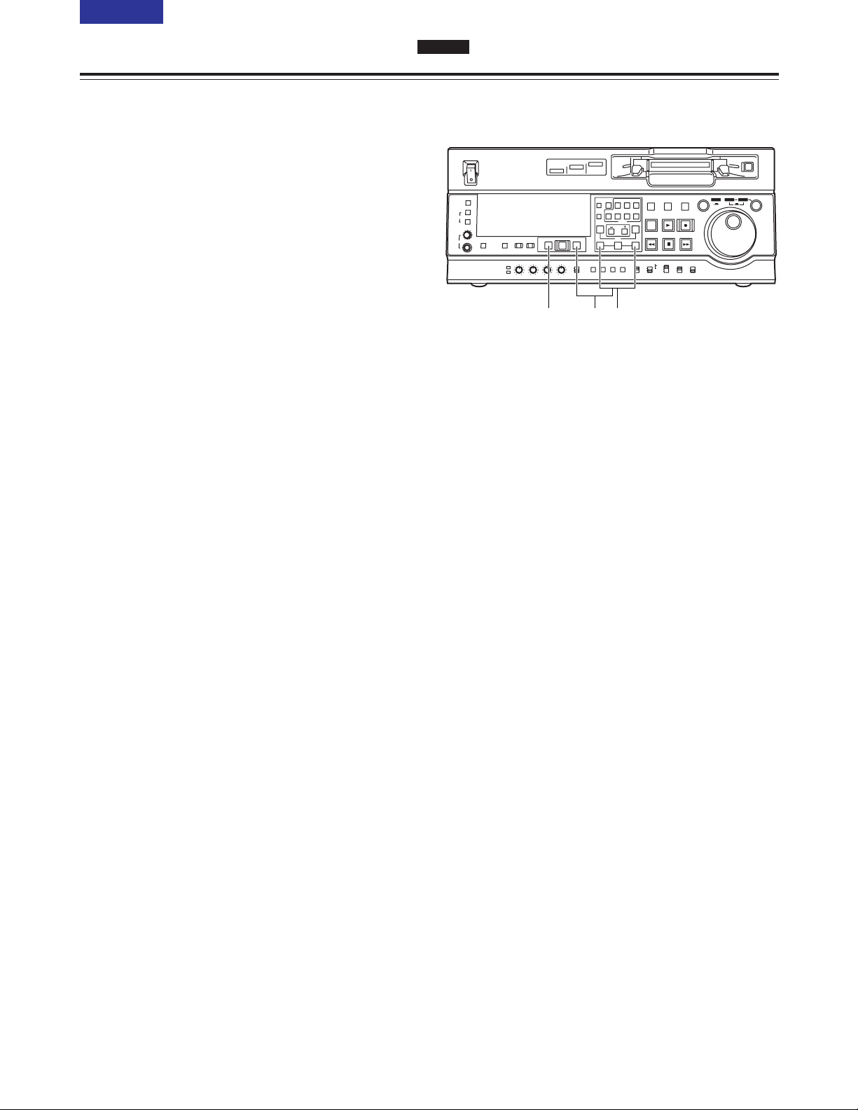
23 (E)
CONTENTS
Automatic editing (deck-to-deck)
SD955B
1
Press the IN (or OUT) button to check the edit
point. The value of the registered edit point
appears on the display panel.
2
While holding down the IN (or OUT) button, press
the PREROLL button and check the picture at the
edit point.
The tape is cued up to the edit IN (or OUT) point,
and a still picture of the point appears.
O If STOP has been selected as the setup menu
No. 315 (AFTER CUE-UP) setting or if the
MODE switch has been set to EE, the VTR is
set to the E-E mode.
3
By holding down the IN and OUT buttons at the
same time, check the editing duration.
The duration appears on the display panel.
How to calculate the duration
O When two edit points have been set:
Duration between the two points
O When only one edit point has been set:
Duration between the data which has been
set and the current address
O When no edit points have been set:
Duration of the previously edited section
4
After the edit points have been registered, press
the PREVIEW button.
Regular preview is now conducted.
<Notes>
O If the edit IN point has not been registered, the
position where the PREVIEW button was
pressed is registered as the edit IN point.
O To stop the preview at any time, press the
STOP button.
O When the PREVIEW button is pressed again
after the IN point during the course of a preview,
the preview will start again from the beginning.
O When the edit OUT point is reached, the tape
stops automatically.
Checking and previewing edit points
ON
OFF
POWER
DV
DVCPRO
DVCPRO 50
METER
L
R
FULL/FINE
MONITOR SELECT
HEADPHONES
MONITOR
MIX
A VOL
SELECT
INPUT SELECT
PREVIEW/PREVIEW
AUTO EDIT
PREROLL
VIDEO
REC LEVEL
CH1
PB LEVEL
AUDIO
CH2 CH3 CH4
TC
PRESET
MENU SET DIAG
SUPER REC INH
INT TCG
MODE
CONTROL
ON
OFF
UNITY
VAR
COUNTER
RESET
A IN
TRIM
SET
OUTIN
A OUT
CH1 CH4CH2
INSERT
CH3
ASSEM
VIDEO CUE TC
STAND BY
EDIT
REW STOP
PLAY REC
PLAYER
RECORDER
FF
JOG SHTL SLOW
TAPE
EE
ON
REGEN
PRESET
EXIT
OFF
REMOTE
LOCAL
4 1/32
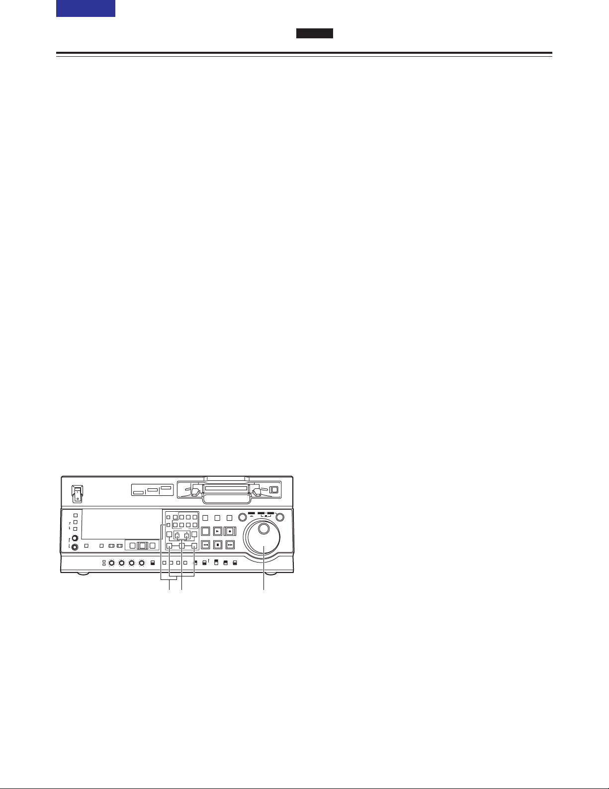
24 (E)
CONTENTS
Automatic editing (deck-to-deck)
SD955B
1
Re-registering an edit point
Locate the new edit point by performing the jog or
shuttle operation, and press the IN (or OUT) button
and SET button at the same time to re-register the
edit point.
2
Modifying an edit point in 1-frame increments
(trimming function)
Press the TRIM button while holding down the IN
(or OUT) button. Each time the + button is
pressed, the point is moved ahead by one frame.
Conversely, each time the – button is pressed, the
point is moved back by one frame.
3
Resetting edit points
O Resetting both an edit IN point and OUT
point
Press the RESET button.
(This takes effect only in the CTL mode.)
O Resetting either an edit IN point or OUT point
Press the RESET button while holding down the
IN (or OUT) button.
<Notes>
O An edit OUT point can be reset even while
editing is in progress.
O In the eject mode, the IN and OUT points are
automatically reset.
Modifying edit points
ON
OFF
POWER
DV
DVCPRO
DVCPRO 50
METER
L
R
FULL/FINE
MONITOR SELECT
HEADPHONES
MONITOR
MIX
A VOL
SELECT
INPUT SELECT
PREVIEW/PREVIEW
AUTO EDIT
PREROLL
VIDEO
REC LEVEL
CH1
PB LEVEL
AUDIO
CH2 CH3 CH4
TC
PRESET
MENU SET DIAG
SUPER REC INH
INT TCG
MODE
CONTROL
ON
OFF
UNITY
VAR
COUNTER
RESET
A IN
TRIM
SET
OUTIN
A OUT
CH1 CH4CH2
INSERT
CH3
ASSEM
VIDEO CUE TC
STAND BY
EDIT
REW STOP
PLAY REC
PLAYER
RECORDER
FF
JOG SHTL SLOW
TAPE
EE
ON
REGEN
PRESET
EXIT
OFF
REMOTE
LOCAL
123
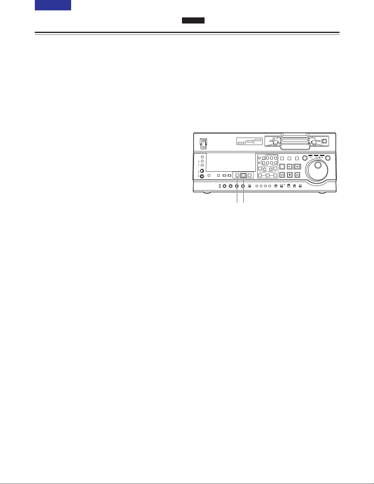
2
Upon completion of the editing, press the REVIEW
button.
Review is then started by the recorder side.
O To stop the review at any time, press the STOP
button.
O When the edit OUT point is reached, the tape is
post-rolled, after which it stops.
1
Press the AUTO EDIT button.
Automatic editing is now executed.
O To suspend editing at any time, press the STOP
button.
O When the edit OUT point is reached, the tape is
post-rolled, after which it stops.
Post-rolling
With assemble editing, editing continues for about
2 seconds after the edit OUT point is passed, the
tape is then returned to the OUT point, after which
it stops.
With insert editing, the PLAY mode is established
after the edit OUT point has been passed, the tape
is then returned to the OUT point, after which it
stops.
The post-roll time can be set using setup menu No.
325 (POSTROLL TM).
Retry function
Even when the STOP button has been pressed to
suspend editing, editing can be repeated from the
beginning simply by pressing the AUTO EDIT
button again.
Auto tag function (recorder side)
If, upon completion of editing, the next edit point
has not yet been registered, the previous edit OUT
point is registered as the IN point and editing is
executed when the AUTO EDIT button is pressed.
To release the auto tag mode, press one of the
transport system buttons (such as the PLAY
button).
Registering an OUT point while editing is in
progress
If the SET button is pressed while the OUT button
is being held down when automatic editing is in
progress, the position corresponding to when the
button was pressed is registered as the OUT point
and the editing operation is exited.
Even if the AUTO EDIT button is pressed, the OUT
point is registered and editing is exited in the same
way.
<Note>
The registered points are automatically cleared
after editing has been executed. However, the
previous edit points can be recalled by pressing
the TRIM+ (or TRIM–) button and SET button at
the same time.
Executing and reviewing automatic editing
ON
OFF
POWER
DV
DVCPRO
DVCPRO 50
METER
L
R
FULL/FINE
MONITOR SELECT
HEADPHONES
MONITOR
MIX
A VOL
SELECT
INPUT SELECT
PREVIEW/PREVIEW
AUTO EDIT
PREROLL
VIDEO
REC LEVEL
CH1
PB LEVEL
AUDIO
CH2 CH3 CH4
TC
PRESET
MENU SET DIAG
SUPER REC INH
INT TCG
MODE
CONTROL
ON
OFF
UNITY
VAR
COUNTER
RESET
A IN
TRIM
SET
OUTIN
A OUT
CH1 CH4CH2
INSERT
CH3
ASSEM
VIDEO CUE TC
STAND BY
EDIT
REW STOP
PLAY REC
PLAYER
RECORDER
FF
JOG SHTL SLOW
TAPE
EE
ON
REGEN
PRESET
EXIT
OFF
REMOTE
LOCAL
12
25 (E)
CONTENTS
Automatic editing (deck-to-deck)
SD955B
 Loading...