

Page 1

ELECTRICAL ADJUSTMENT
CONTENTS
1. Introduction of Electrical Adjustment ........................................................................................... ELE-1
1-1. Adjustment after replacement of major parts ....................................................................... ELE-1
1-2. Adjustment Item .................................................................................................................... ELE-2
1-3. PC EVR Software ................................................................................................................. ELE-3
1-3-1. Connection ................................................................................................................. ELE-3
1-3-2. Setup of EVR software ............................................................................................... ELE-4
1-3-3. Button operation ......................................................................................................... ELE-4
2. Camera Adjustment Procedure ................................................................................................... ELE-19
2-1. Preparation ........................................................................................................................... ELE-19
2-1-1. Initial settings ............................................................................................................. ELE-19
2-1-2. Save the backup data ................................................................................................ ELE-19
2-2. IRIS OIS GYRO Adjustment. ................................................................................................ ELE-20
2-3. ZOOM Lever Adjustment. ..................................................................................................... ELE-20
2-4. IRIS Diameter Adjustment. ................................................................................................... ELE-21
2-5-1. Sensitivity Adjustment. ...................................................................................................... ELE-22
2-5-2. Sensitivity Confirmation. .................................................................................................... ELE-23
2-6. Zoom tracking / De-focus Adjustment. ................................................................................. ELE-24
2-7. White Balance Adjustment (3100K). .................................................................................... ELE-26
2-8. White Balance Adjustment (5600K). .................................................................................... ELE-27
2-9. White Shading Adjustment. .................................................................................................. ELE-28
2-10. Black Blemish Compensation. ............................................................................................ ELE-29
2-11. ND Filter Adjustment .......................................................................................................... ELE-30
2-12. VBS Level Adjust (59.94Hz) ............................................................................................... ELE-31
2-13. VBS Level Adjust (50Hz). ................................................................................................... ELE-32
2-14. INT Clock Frequency Adjustment ....................................................................................... ELE-33
2-15. LCD Back Light Adjustment................................................................................................ ELE-34
2-16. LEVEL Gauge Adjustment.................................................................................................. ELE-34
2-17. MIC Balance Adjustment .................................................................................................... ELE-35
2-18. Time / Zoon Setting ............................................................................................................ ELE-35
2-19. White Blemish Confirmation ............................................................................................... ELE-36
2-20. Black Blemish Confirmation................................................................................................ ELE-36
2-21. White Shading Confirmation ............................................................................................... ELE-36
Model No. : AJ-PX270/EJ, AJ-PX285MC,298MC
Page 2
NO
ADJUSTMENT
Zoom
PCB
Handle
OP PCB
INT
MIC
2-2
IRIS OIS GYRO
X X X X
2-3
ZOOM Lever
X X
2-4
IRIS Diameter
X X X
2-5
Sensitivity
X X X
2-6
Zoom tracking/De-focus
X X X
2-7
White Balance (3100K)
X X
2-8
White Balance (5600K)
X X
2-9
White Shading
X X
Black Blemish
Compensation
2-11
ND Filter
X X
2-12
VBS LEVEL (59.94Hz)
X X
2-13
VBS LEVEL (50Hz)
X X
2-14
INT Clock Frequency
X X
2-15
LCD Back Light
X X
2-16
LEVEL Gauge
X X X X
2-17
MIC Balance
X X X X X
2-18
Time / Zone setting
X X
White Blemish
Confirmation
1. Introduction of Electrical Adjustment
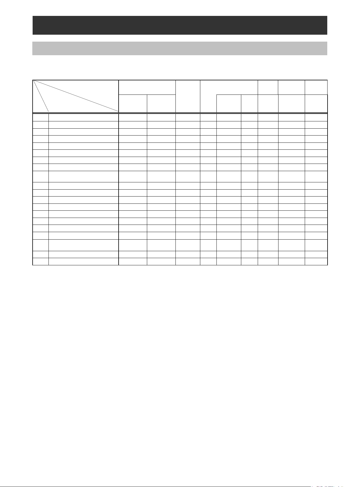
1-1. Adjustment after replacement of major parts
When the fol lowing parts is replaced showing in the table below, the adjustment and confirmation are required follow the
items shown by mark “X” in the table.
PART NAME
*MAIN P.C.B.
When
Backup
When no
backup
LENS
Unit
HANDLE Unit
GRIP
Unit
SW
LCD
Unit
Monitor
PCB
Battery
Unit
Battery
PCB
2-10
2-19
X X
X X X
X: Adjustment / Confirmation Required
The method of data backup (CAM EEPROM) has been described to the item “7. Data Backup Procedure” of service
information (SECTION 1).
The method of white blemish compensation has been described to the item “8. White Blemish Compensation” of service
information (SECTION 1).
ELE-1
Page 3
ADJUSTMENT ITEM
Required Tool and equipment
Remark
Save
AUTO
Adj.
LENS
EEPROM
Manual
Adj.
LENS
EEPROM
Gray Scale Chart
HD SDI WFM
Manual
LENS
AUTO
LENS
EEPROM
Gray Scale Chart
HD SDI WFM
Manual
CAM
Gray Scale Chart
Vector scope
AUTO
CAM
CC filter (VFK1347,VFK1884,VFK1888)
Vector scope
AUTO
CAM
White Chart
Color Pyrometer & Lux Meter
AUTO
CAM
White Chart
Color Pyrometer & Lux Meter
AUTO
CAM
Gray Scale Chart
Color Pyrometer & Lux Meter
AUTO
CAM
Manual
Adj.
BE
SD NTSC/PAL Composite Signal Generator
SD WFM or Oscilloscope
Manual
Adj.
BE
AUTO
Adj.
BE
AUTO
Adj.
BE
Manual
Adj.
BE
AUTO
Adj.
BE
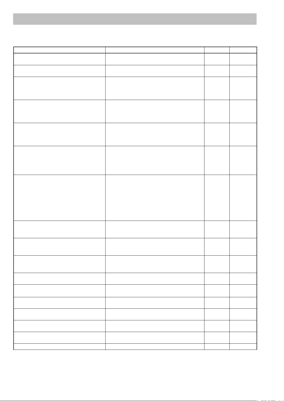
1-2. Adjustment Item
Below indicated tools are required to perform each adjustment in addition to tools in introduced in item 1-1-1.
IRIS OIS GYRO Adjustment Unnecessary
ZOOM Lever Adjustment Unnecessary
IRIS Diameter Adjustment
Zoom tracking and De-focus Adjustment
Sensitivity Adjustment
White Balance Adjustment (3100K)
White Balance Adjustment (5600K)
Halogen lamp
Color Pyrometer & Lux Meter
Halogen lamp
Collimator (RFKZ0422)
Collimator Adaptor
Halogen lamp
Color Pyrometer & Lux Meter
Halogen lamp
Color Pyrometer & Lux Meter
WFM
Filter holder (VFK1345)
Step down ring (VFK1346)
Gray Scale Chart
Halogen lamp
Color Pyrometer & Lux Meter
WFM
Adj.
Adj.
Adj.
Adj.
Adj.
EEPROM
EEPROM
CAM
EEPROM
EEPROM
EEPROM
White Shading Adjustment
Black Blemish Compensation
ND FILTER Compensation Adjustment
Video Output Level Adjustment SD WFM or Oscilloscope
Int. Clock Frequency Adjustment
Level Gauge Adjustment Level Gauge
MIC Balance Adjustment Unnecessary
LCD Back Light Adjustment Unnecessary
Time / Zone setting Unnecessary
Halogen lamp
Halogen lamp
Halogen lamp
ELE-2
Adj.
Adj.
Adj.
EEPROM
EEPROM
EEPROM
Page 4
NAME
Part Number
Pcs.
Remark
PC EVR software
VVS0114
1
Download from the Global Service WEB site.
USB Driver for AG-HPX250/260 EVR Adjustment
VSI5386B
1
Download from the Glob al Service WEB site.
USB cable A type ↔ mini B type
--- 1
Personal Computer
---
1
*NOTE:
USB cable
mini B type
A type
STOP
RESET
EXIT
1-3. PC EVR software
All adjustments are performed by PC EVR software “VVS0114”.
When the PC EVR software is used, the following tools are required.
*OS: Windows XP SP2 / SP3, Windows7 32bit
In order to communicate with PC EVR software “VVS0114”, it is necessary to install USB driver software
“VSI5386B” in PC. Please refer to “6-2. Setu p” of section1.
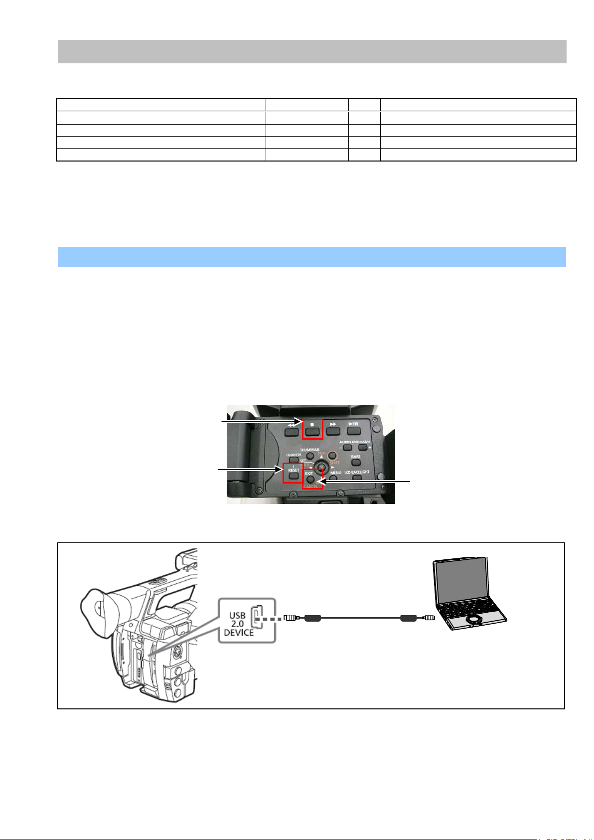
1-3-1. Connection
1. Set this camera recorder to COM mode.
< Setting method of COM mode >
1-1. Turn the power on.
1-2. The COM mode is set b y hold down the “STOP” button, “EXIT” button and “RESET” button at the same
time for three s econds or more. (The character of “COM*” is displayed on the LCD screen when the COM
mode is set.).
NOTE: To cancel the COM mode, execute the oper ation of the same button as the s etting. If the “ * “ mar k has
disappeared, COM mode is cancelled. When the power is turned ON next time, COM character disappears.
2. Connect the USB cable between USB connector and PC.
ELE-3
Page 5
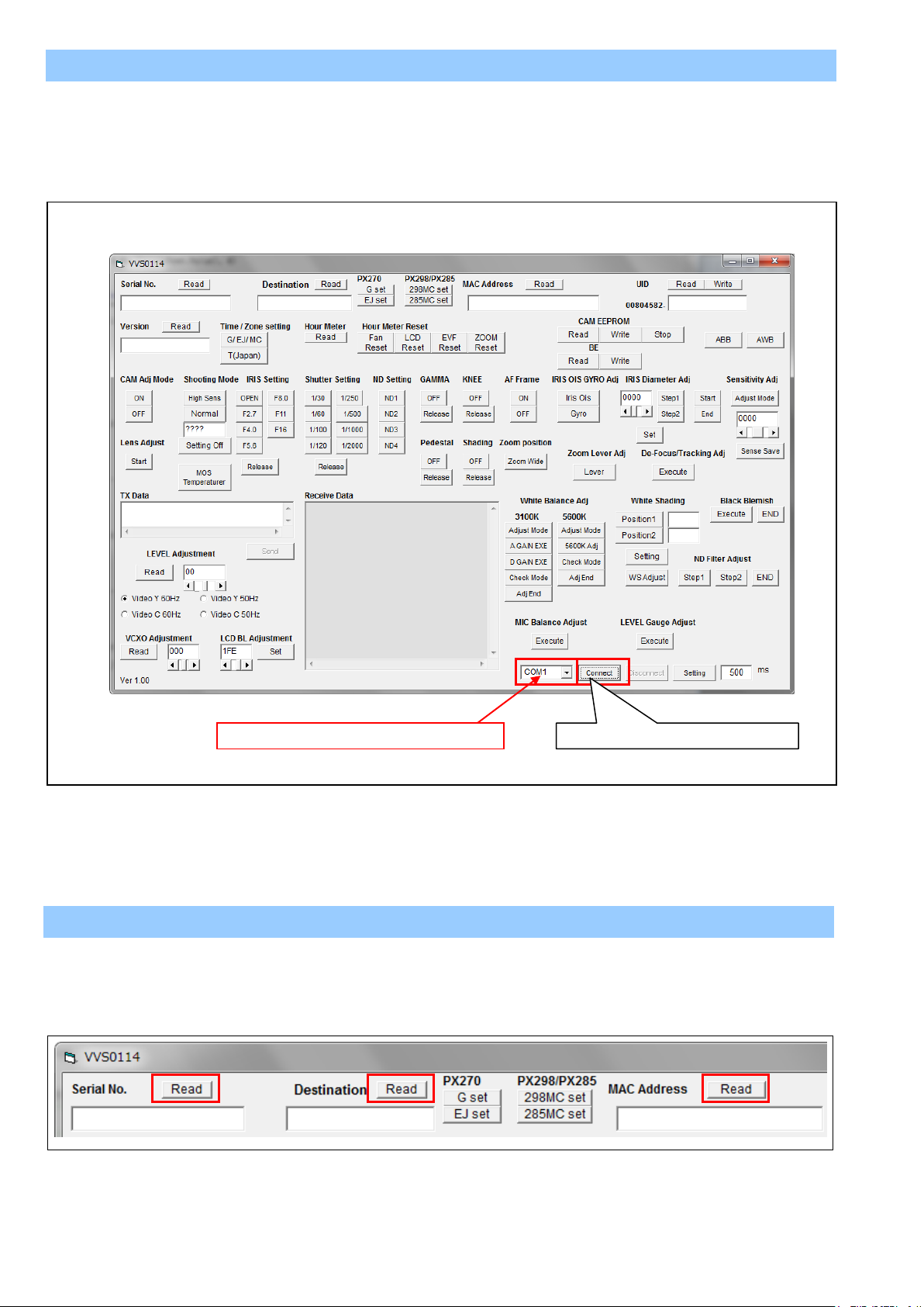
1-3-2. Setup of EVR software
Select COM port number of your PC.
Communication starting button
1. Download the file “PC EVR Software (VVS0114)” from Global Service Web Site.
2. Make any directory and then copy all files in VVS0114.
3. Double click the “vvs0114.exe” in the “vvs0114” folder to boot-up the software. The following screen is
displayed.
4. After selecting COM port, click the “Connect” button to start communication between Camera and VVS0114.
1-3-3. Button operation
< 1. Serial No. / Destination / MAC Address Read >
Clicking “Read” button for Serial No., Serial No. is displayed.
Clicking “Read” button for Model Name, Model Name is displayed.
Clicking “Read” button for MAC Address, MAC Address is displayed.
ELE-4
Page 6
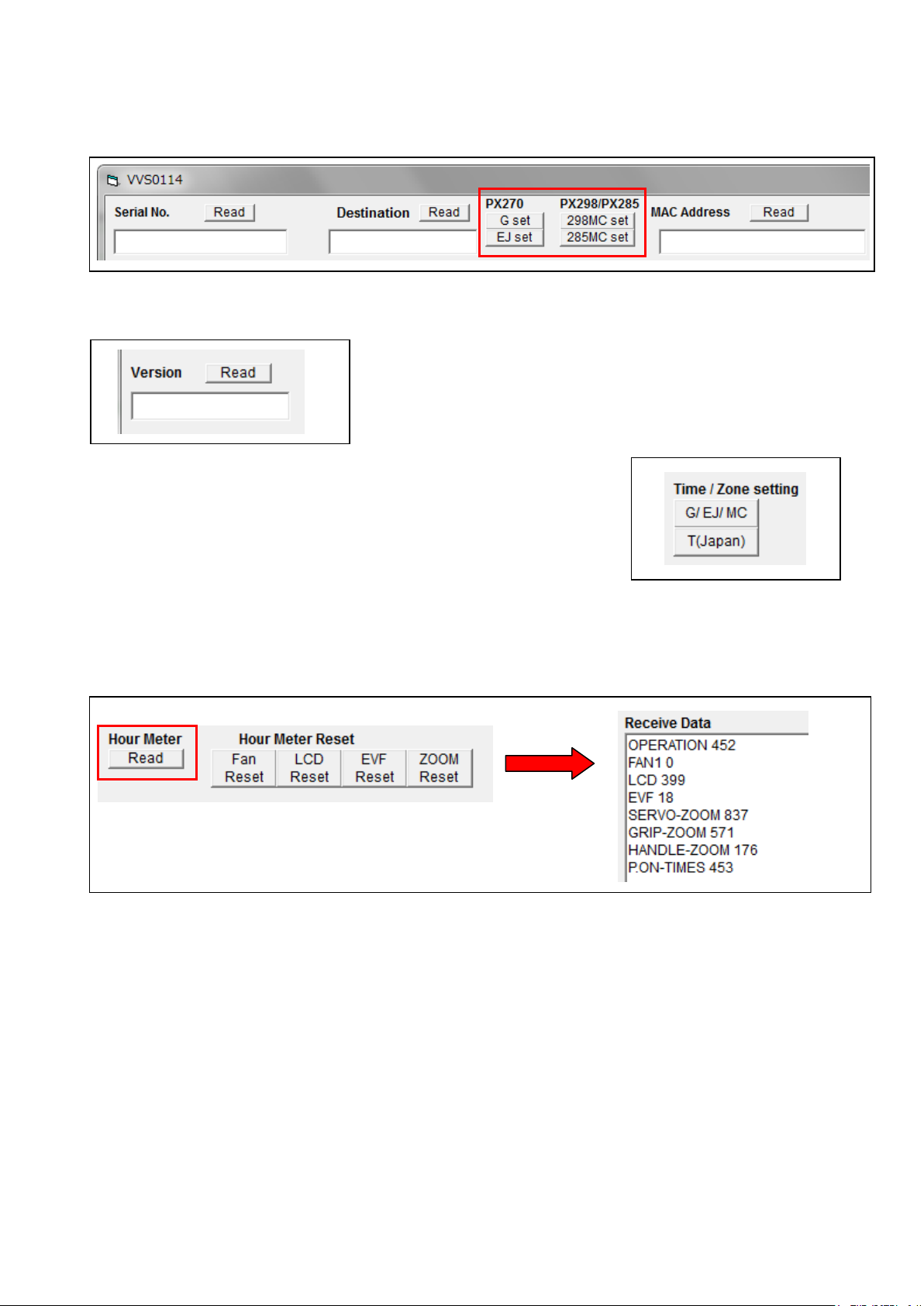
< 2. Destination setting >
After replacing the Main P.C.B, execute the Destination setting.
AJ-PX270(Japan), P, EN, AN, PX : Click “G set” button.
AJ-PX270EJ : Click “EJ set” button.
AJ-PX298MC : Click “298MC set” button.
AJ-PX285MC : Click “285MC set” button.
< 3. Version read >
Clicking “Read” button for Version, the total number of the firmware version is displayed.
< 4. Time / Zone setting >
The time and time zone of the internal clock is set.
AJ-PX270P,EJ,EN,AN,PX/PX298MC/285MC : Click “G / EJ / MC” button.
AJ-PX270(Japan) : Click “T(Japan)” button.
< 5. Hour Meter information >
Clicking “Read” button for Hour Meter, the hour meter information is displayed in Receive Data window.
NOTE: FAN hour meter is the effective information after Ver2 firmware.
OPERATION : Total operation hour
FAN1 : FAN operation hour
LCD : LCD operation hour
EVF : EVF operation hour
SERVO-ZOOM : ZOOM motor moving times
GRIP-ZOOM : GRIP ZOOM button operation times
HANDL-ZOOM : HANDLE ZOOM button operation times
P.ON-TIMES : The number of times of turning on power
< 6. Hour Meter Reset >
Clicking “Fan Reset” button, the hour meter of FAN is set zero hour.
When replacing FAN, click “Fan Reset” button for FAN Hour Meter.
NOTE: FAN hour meter reset is the effective function after Ver2 software.
ELE-5
Page 7
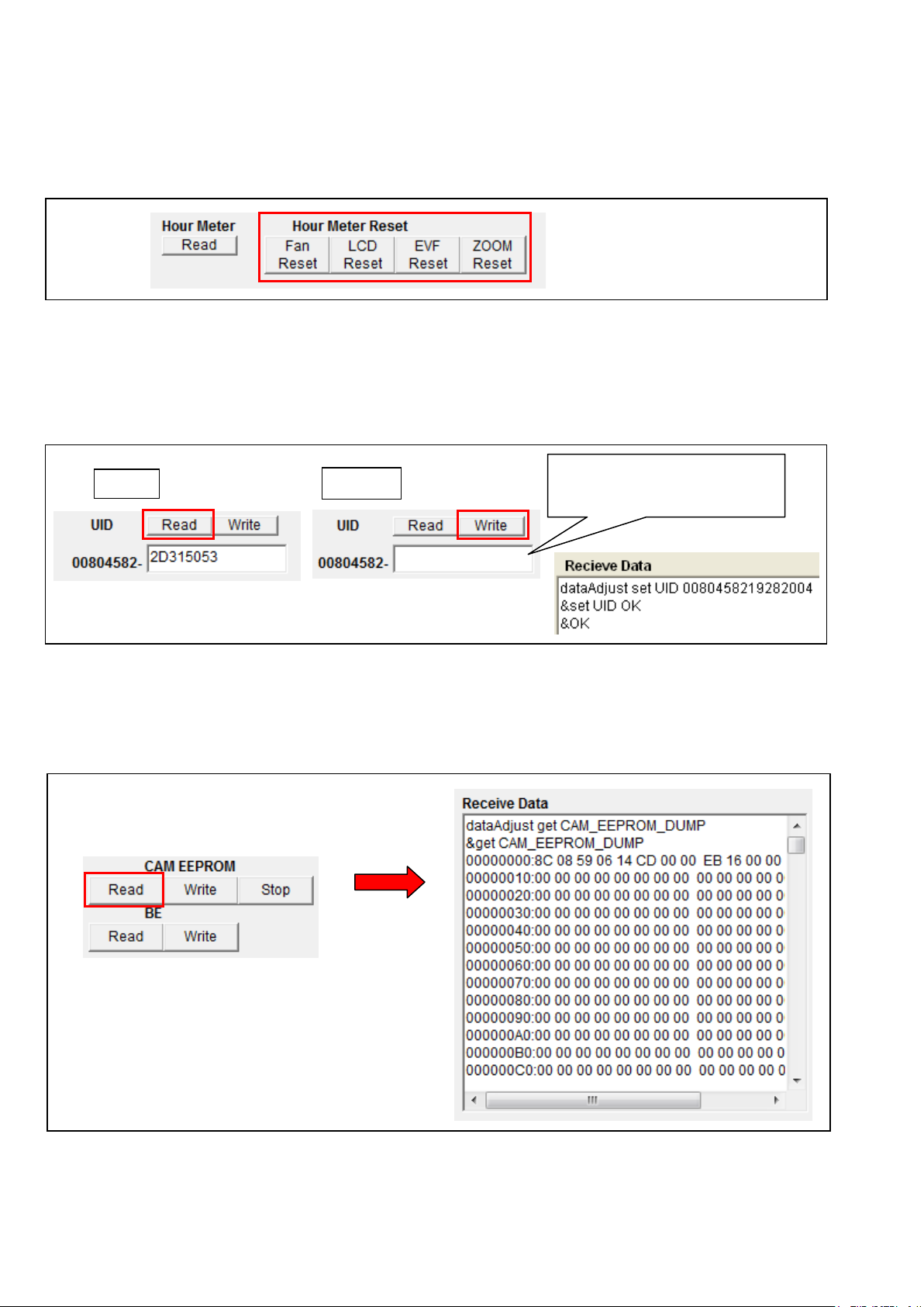
Clicking “LCD Reset” button, the hour meter of LCD is set zero hour.
Read
Write
Input a number.
When replacing LCD, click “LCD Reset” button for LCD Hour Meter.
Clicking “EVF Reset” button, the hour meter of EVF is set zero hour.
When replacing EVF, click “EVF Reset” button for EVF Hour Meter.
Clicking “ZOOM Reset” button, the hour meter of SERVO-ZOOM motor is set zero hour.
When replacing ZOOM motor , click “ZOOM Reset” button for SERVO-ZOOM Hour Meter.
< 7. UID reading and writing >
Clicking “Read” button for UID, UID number is displayed.
When writing UID, input a number (8 figures) in the window and then click “Write” button.
If the number which should be written is not known, click “Write” button with a blank .
A number is generated and written in automatically.
When “&set UID OK” is displayed in Receive Data window, the writing is completed.
If unknown, with a blank.
< 8. CAM EEPROM READ >
Click “Read” button of CAM EEPROM. When Dump Data is displayed in RX Data window, Data Backup is
completed. It takes approx. 15 seconds.
Backup Data is saved as “PX270_yy_mm_dd_hh_nn.txt” file in “SaveRom” folder of vvs0114.
yy: year, mm: month, dd: day, hh: hour, nn: minute
ELE-6
Page 8
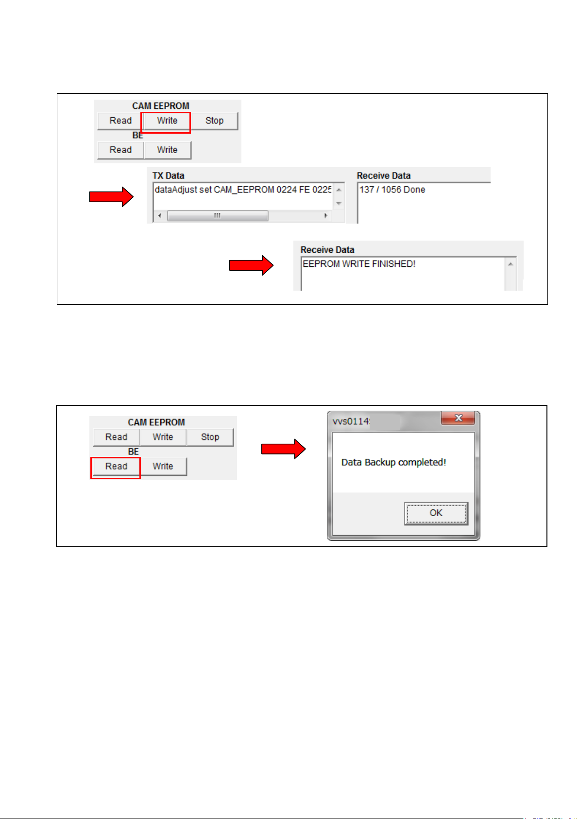
< 9. CAM EEPROM WRITE >
1. Click “Write” button of CAM EEPROM. File selection dialog opens.
2. Select a backup file which you want to write from SaveRom folder.
3.Clicking “Open” button, the writing starts. When “EEPROM W RITE FINISHED!” is displayed in Receive
Data window, the writing is completed.
It takes approx. 9 minutes by the completion.
< 10. BE DATA READ >
Click “Read” button of BE. When “Data Backup completed!” message is displayed, Data Backup is completed. It
takes approx. 15 seconds.
NOTE: Backup Data is saved as “PX270_backup_yy_mm_dd_hh_nn.TXT” file in “SysBackup” folder of
vvs0114.
yy: year, mm: month, dd: day, hh: hour, nn: minute
ELE-7
Page 9
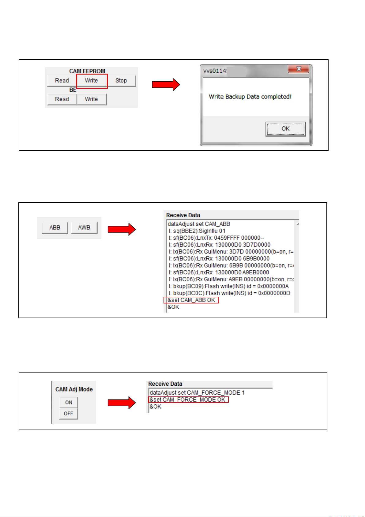
< 11. BE D ATA WRITE >
1. Click “Write” button of BE. File selection dialog opens.
2. Select a backup file which you want to write from SysBackup folder.
3.Clicking “Open” button, the writing starts. When “WRITE Backup Data Completed!” message is
displayed, the writing is completed.
It takes approx. 10 seconds by the completion.
< 10. AWB / ABB >
Clicking “AWB” button, AWB is executed.
Clicking “ABB” button, ABB is executed.
When “&set CAM_ABB OK” or “&set CAM_AWB OK” is displayed in Receive Data window,
ABB (AWB) is completed.
< 11. CAM Adj. Mode setting >
It is a button which makes Camera adjustment mode.
In case of setting to adjustment mode, click “ON” button.
In case of releasing from adjustment mode, click “OFF” button.
When “&set CAM_FORCE_MODE OK” is displayed in Receive Data window, the setting is completed.
ELE-8
Page 10
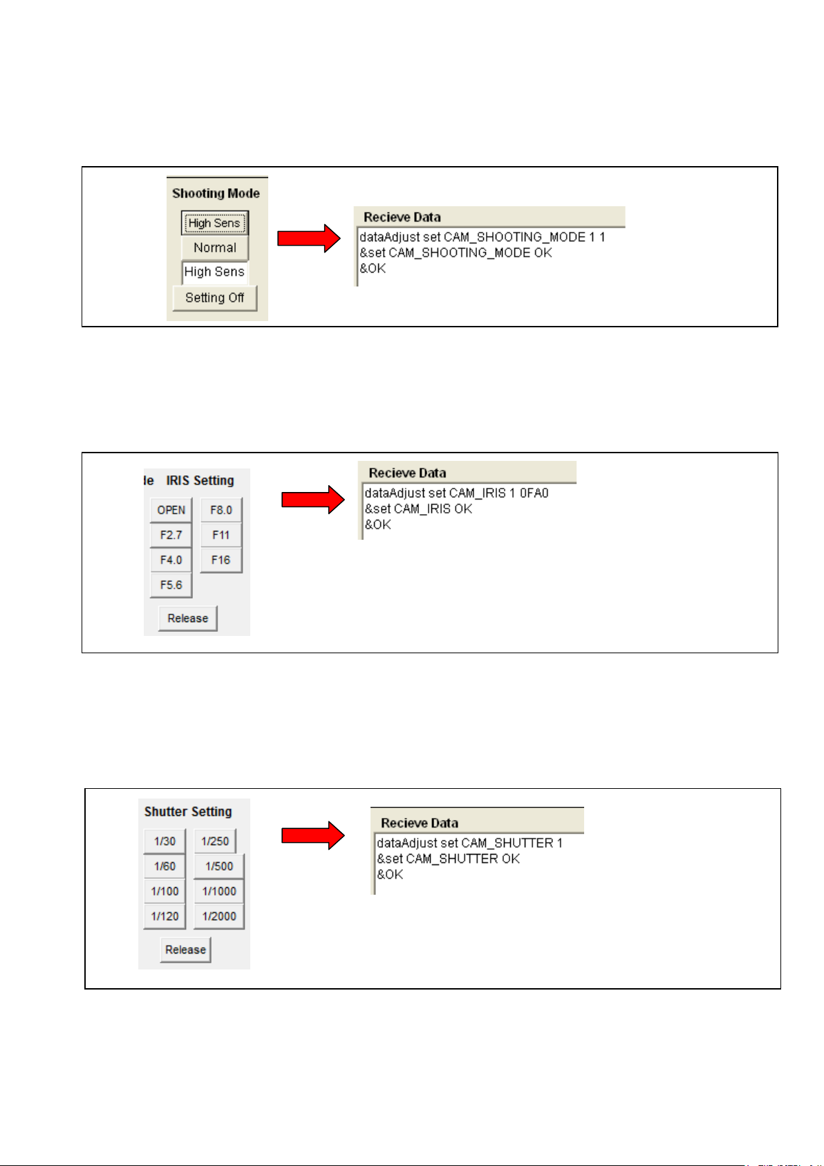
< 12. Shooting Mode setting >
Shooting mode can be changed with this button.
High Sens : Camera setting is set to High sensitivity mode.
Normal : Camera setting is set to Normal sensitivity mode.
Setting Off : The compulsive setting from PC is released.
When “&set CAM_SHOOTING_MODE OK” is displayed in Receive Data window, the setting is completed.
< 13. IRIS setting >
It is possible to set IRIS to the iris value indicated on each button.
Release : The compuls ive s etting from PC is released.
When “&set CAM_IRIS OK” is displayed in Receive Data window, the setting is completed.
< 14. Shutter setting >
It is possible to set Shutter to the shutter value indicated on each button.
Release : The compuls ive s etting from PC is released.
When “&set CAM_SHUTTER OK” is displayed in Receive Data window, the setting is completed.
ELE-9
Page 11
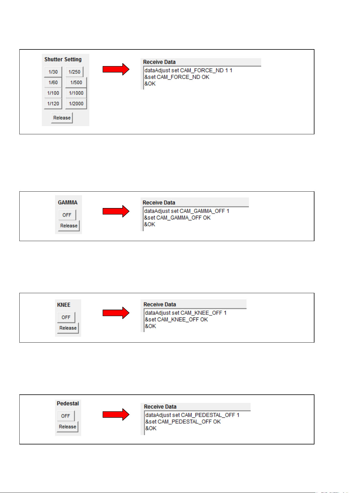
< 15. ND filter setting >
It is possible to set ND filter to the ND filter position indicated on each button.
When “&set CAM_FORCE_ND OK” is displayed in Receive Data window, the setting is completed.
< 16. GAMMA OFF setting >
It is possible to set GAMMA to OFF.
OFF : GAMMA is set to OFF.
Release : The compuls ive s etting from PC is released.
When “&set CAM_GAMMA_OFF OK” is displayed in Receive Data window, the setting is completed.
< 17. KNEE OFF setting >
It is possible to set KNEE to OFF.
OFF : KNEE is set to OFF.
Release : The compuls ive s etting from PC is released.
When “&set CAM_KNEE_OFF OK” is displayed in Receive Data window, the setting is completed.
< 18. PEDESTAL OFF setting >
It is possible to set PEDESTAL to OFF.
OFF : PEDESTAL is set to OFF.
Release : The compuls ive s etting from PC is released.
When “&set CAM_PEDESTAL_OFF OK” is displa yed in Receive Data window, the setting is completed.
ELE-10
Page 12
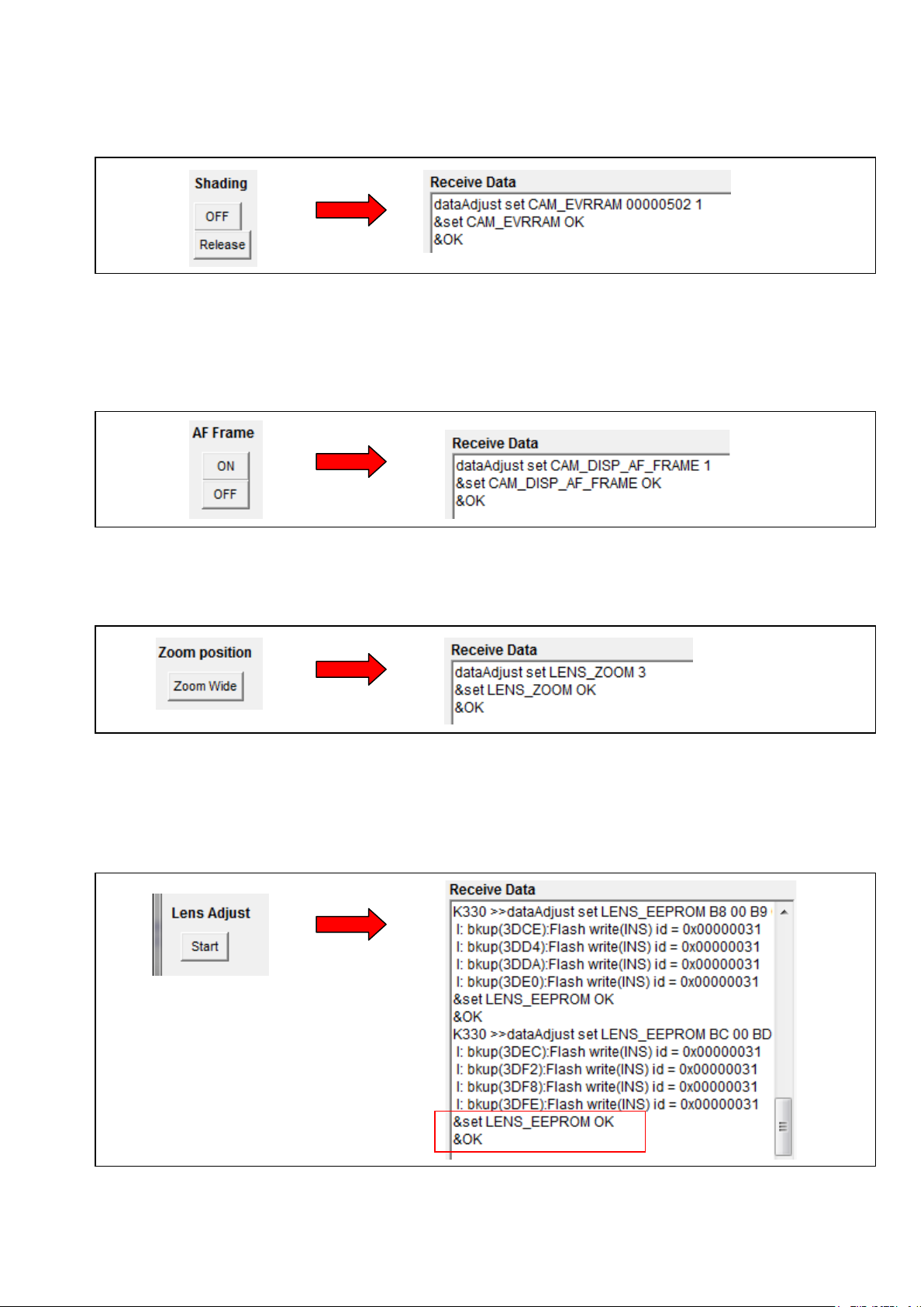
< 19. White Shading OFF setting >
It is possible to set White Shading to OFF.
OFF : White Shading is set to OFF.
Release : The compuls ive s etting from PC is released.
When “&set CAM_EVRRAM OK” is displayed in Receive Data window, the setting is completed.
< 20. AF Frame ON/OFF setting >
When adjusting Zoom Tracking, It is a button for displaying the focus window on the LCD panel.
ON : Focus window display ON
OFF : Focus window display OFF
When “&set CAM_DISP_AF_FRAME OK” is displayed in Receive Data window, the setting is completed.
< 21. Zoom position Wide setting >
It is possible to set Zoom position to Wide terminal.
When “&set LENS_ZOOM OK” is displayed in Receive Data window, the setting is completed.
< 22. Lens Adjustment St art >
In case of replacing Lens Unit or Main P.C.B, be sure to click this “Start” button before start ing Lens Adju stment.
By clicking this button, the initial setting data is set to EEPROM.
When “&set LENS_EEPROM OK” is displayed at the last line in Receive Data window, the initial setting is
completed.
ELE-11
Page 13

< 23. IRIS OIS GYRO A djustment >
When executing IRIS/OIS and GYRO adjustment, use these buttons.
IRIS OIS : for executing IRIS/OIS adjustment (Auto adjustment).
GYRO : for executing GYRO adjustment (Auto adjustment)
When “All Adjust Finish” is displayed in Receive Data window, the adjustment is completed.
If “NG” is displayed, Re-adjust again.
< 24. ZOOM Lever Adjustment >
When executing ZOOM lever adjustment, use this button. This button is clicked 6 times while adjusting.
When “Get All Data. Adjust Data Backup to E2P” i s displayed in Receive Data window at the last cl icking, the
adjustment is completed.
If “Out of Range! Please Get ****** Again” is displayed, Re-adjust again.
ELE-12
Page 14

Adjustment button
< 25. IRIS Diameter Adjustment >
When executing IRIS Diameter adjustment, use these 6 buttons and 1 adjustment button.
Be sure to click “Start” button befor e start in g t he adj u s tm ent. B y cl ic king this button, the ini tia l s etti ng data is set to
EEPROM.
Be sure to click this “End” button after completing the adjustm ent.
“Step1” is a button for the coarse adjustment of IRIS Diameter F5.6.
“Step2” is a button for the coarse adjustment of IRIS Diameter F11.
“Set” is a button for savin g the adjustment v alue of IRIS Diam eter, and also “Set” button is c licked 3 times while
adjusting.
When “&set LENS_IRISOIS OK” is displayed in Receive Data window 3 times, the adjustment is completed.
When “&set LENS_IRISOIS NG” is displayed in Receive Data window, re-adjust again.
The “Adjustment” button operates only in the direction which closes IRIS.
< 26. De-Focus/T racking Adjust >
When adjusting De-Focus and Zoom Tracking, use this button. Collimator and adaptor are necessary.
Execute : Adjustment automatically starts.
When “&set CAM_LENS_TRACKING OK” is displayed at last line in Receive Data window, the adjusting is
completed. Adjusting time takes about 1 minute.
When “&set CAM_LENS_TRACKING NG” is displayed in Receive Data window, re-adjust again.
ELE-13
Page 15

< 27. Sensitivity Adjust >
Release
adjustment mode
5600K Adjustment
Mode setting
Execute 5600K
adjustment
Total check
mode setting
3100K Adjustment
Mode setting
Execute A Gain
adjustment
Execute D Gain
adjustment
Total check
mode setting
Release
adjustment mode
Adjust Mode setting
Adjustment button
Save adjustment value
Adjust Start & End
setting
When adjusting Sensitivity, use these buttons.
Be sure to click “Start” button befor e start in g t he adj u s tm ent. B y cl ic king this button, the ini tia l s etti ng data is set to
EEPROM. Be sure to click this “End” button after completing the adjustment.
Adjust Mode : for setting to Sensitivity adjustment mode.
When “&set CAM_STD_SENSITIVE OK” is displayed in Receive Data window, the setting is completed.
Scroll button : for adjusting Sensitivity. Clicking button, G-ch level of White can be changed.
When “&set CAM_STD_SENSITIVE OK” is displayed in Receive Data window, the setting is successful .
Sens Save : for saving the Sensitivity adjustment value.
When “&set CAM_STD_SENSITIVE OK” is displayed in Receive Data window, the saving is completed.
< 28. White Balance Adjust >
When adjusting White Balance, use these buttons.
Adjust Mode : for setting to White balance adjustment mode.
When “&set CAM_WHITE_BALANCE OK” is displayed in Receive Data window, the setting is completed.
A GAIN EXE : for adjusting Analog Gain of White balance (3100K). (Auto adjustment)
When “&set CAM_WHITE_BALANCE OK” is displayed in Receive Data window, the adjusting is completed.
D GAIN EXE : for adjusting Digital Gain of White balance (3100K). (Auto adjustment)
When “&set CAM_WHITE_BALANCE OK” is displayed in Receive Data window, the adjusting is completed.
5600K Adj : for adjusting 5600K White balance. (Auto adjustment) CC filter is necessary.
When “&set CAM_WHITE_BALANCE OK” is displayed in Receive Data window, the adjusting is completed.
Check Mode : Clicking this button, the monitor checking mode of white balance is set. (AWB setting = PRE 3.2K)
Adj End : Clicking this button, the White Balance adjustment mode is released.
ELE-14
Page 16

Execute White Shading
Position1, 2 setting
Shutter value setting
Shutter value display
< 29. Black Blemish compensation >
Blemish compensation is auto adjustment.
Execute : Clicking this button, the compensation starts. It takes approx. 5??? seconds by the completion.
END : After the adjustment, click this button. Adjustment mode is released.
When “&set CAM_DEFECT OK” is displayed in Receive Data window, the compensation is completed.
< 30. White Shading adjustment >
When adjusting White Shading, use these buttons.
It is necessary to set the shutter value in two positions before executing this adjustment.
Position1 : for s etting shutter value at Posit ion1. After clicking this button, whe n clicking shutter button, shutter
value is displayed in the right window.
Position2 : for s etting shutter value at Posit ion2. After clicking this button, whe n clicking shutter button, shutter
value is displayed in the right window.
Setting : for setting two shutter value
WS Adjust : for White Shading adjustment. Clicking this button, White Shading adjustment automatically starts.
When “&set CAM_SHADING OK” is displayed in Receive Data window, the adjustment is completed. It takes
approx. 10 seconds by completion.
adjustment
ELE-15
Page 17
Input a check m ark in the
Adjustment value display
Adjustment button
Adjustment
Adjustment
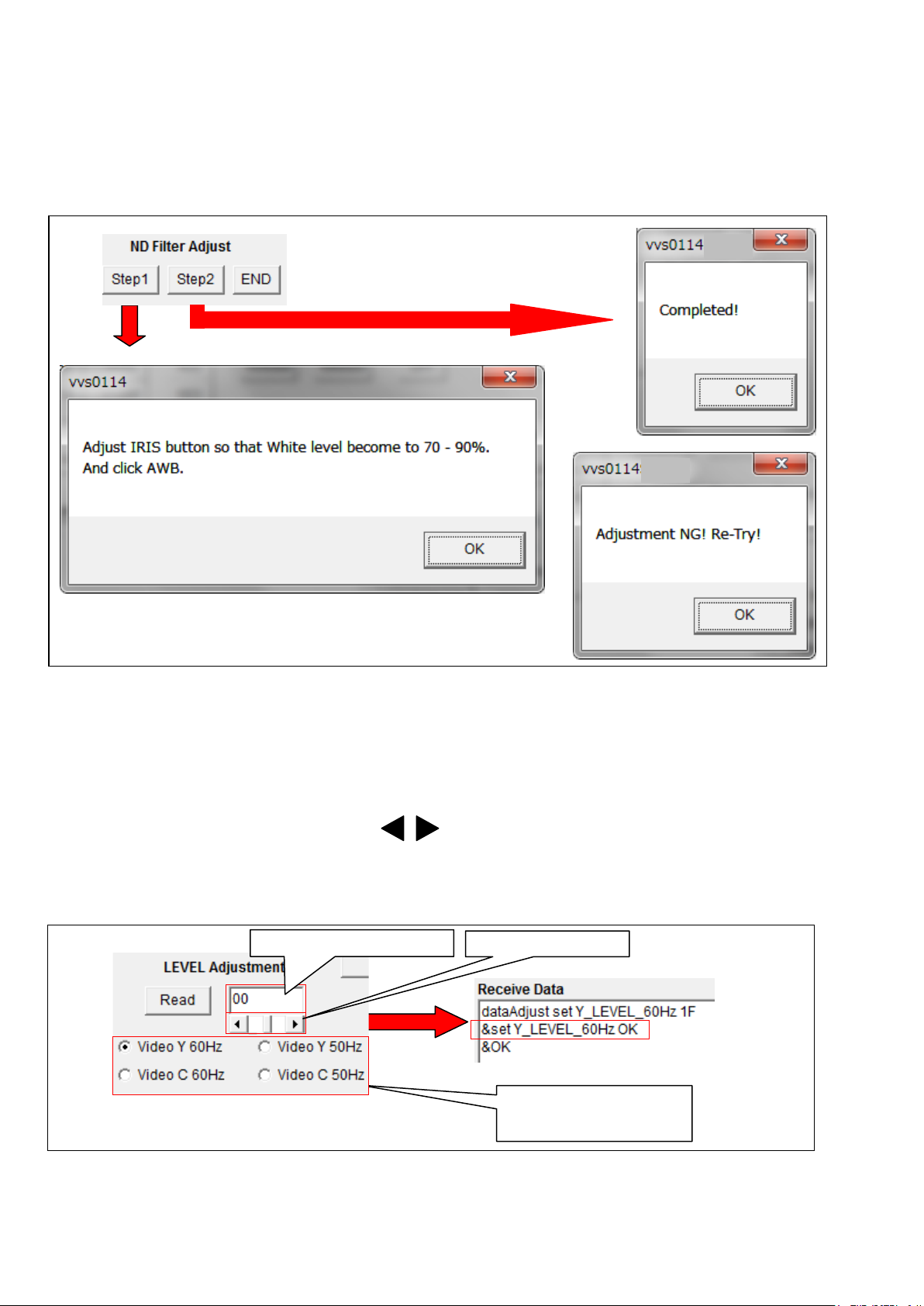
< 31. ND Filter adjustment >
When executing ND Filter adjustment, use these buttons.
Step1 : for setting ND filter adjustment mode. After settings completed, Message box opens.
Step2 : Clicking this button, the adjustment of ND2, ND3, and ND4 is automatically executed.
When the adjustment is OK, “Completed” message opens.
When the adjustment is NG, “Re-Try” message opens.
END : The adjustment mode is released.
OK
NG
< 32. LEVEL A djustment >
When adjusting each Video level, use these buttons.
Read : Clicking this button, the adjustment value is displayed.
Scroll button : for adjusting each level. Clicking button, each video level can be changed.
When “&set Y_LEVEL_60Hz OK” or “&set C_LEVEL_60Hz OK” or “&set Y_LEVEL_50Hz OK”… is displa yed
in Receive Data window, the setting is successful .
Check button : Input a check mark in the adjustment item.
adjustment item
ELE-16
Page 18

Adjustment button
Adjustment value display
Adjustment value display
Adjustment button
After adjustment, click Set
OK
< 33. INT Clock Frequency Adjustment >
When adjusting INT 27MHz Clock frequency, use these buttons.
Read : Clicking this button, the adjustment value is displayed.
Scroll button : for adjusting INT 27MHz frequency. Clicking button, the frequency can be changed.
When “&set 27M_VCXO OK” is displayed in Receive Data window, the setting is successful .
< 34. LCD Back Light Adjustment >
When adjusting LCD back light, use these buttons.
Scroll button : for adjusting LCD back light. Clicking button, the brightness of the back light can be
changed.
When “&set LCD_BL_0 OK” is displayed in Receive Data window, the setting is successful .
Set : After the adjustment, click this button so that the adjustment value is registered.
< 35. MIC Balance Adjust >
When adjusting internal MIC Balance, use this button.
Execute : Adjustment automatically starts.
When “&set INT_MIC_LEVEL OK” is displayed in Receive Data window, the adjusting is completed.
When “&set INT_MIC_LEVEL NG” is displayed in Receive Data window, re-adjust again.
ELE-17
Page 19

Port setting
OK
Temperature
< 36. LEVEL Gauge Adjust >
When adjusting Level Gauge Balance, use this button.
Execute : Adjustment automatically starts.
When “&set LEVEL_GAUGE OK” is displayed in Receive Data window, the adjusting is completed.
When “&set LEVEL_GAUGE NG” is displayed in Receive Data window, re-adjust again.
< 37. MOS Tem per at ur e >
It is possible to confirm MOS temperature.
When clicking this button, MOS temperature is displayed in Receive Data window.
In the following example, MOS temperature is 56 degree.
< 38. Other >
COM Port and communication setting can be set in the communication un-connection.
Communication
setting button
It is possible to change from COM1 to COM6 in the port setting. Please set to the COM port number of PC.
Clicking “SETTING” button, the following screen is displayed and following items can be set.
● Baud Rate, ● Party, ● Data Length, ● Stop Bit
The setting need not be changed.
ELE-18
Page 20

2. Camera Adjustment Procedure
2-1-1. Initial settings
2-1-2. Save the backup data
Back up the Scene File and User File into SD card.
Restore the Scene File and User File to Camera.
Adjustment is completed.
2-1. Preparation
Unless otherwise specified, please execute adjustment by the following setting.
< Lighting >
For the lighting source, use a halogen lamp of 3,100K±50K, 500W and set it to get 2,000lx evenly on the surface of object.
< SW Setting >
Set the
AUTO/MANUAL : MANUAL
GAIN : L
WHITE BAL SW : B
SHUTTER : OFF
USER SW : OFF
ND FILTER : OFF
ZOOM SW : SERVO
FOCUS SW : AUTO
IRIS mode : MANUAL IRIS
IN/OUT SW : OUT
< MENU Setting >
Set the
SYSTEM MODE -> LINE & FREQ : 1080/59.94i
OUTPUT SEL -> SDI OUT : ON
OUTPUT SEL -> VIDEO OUT : ON
Procedures for Electrical Adjustment premised that the MENU settings were original (factory standard) setting.
Before adjustment, save the data of user settings and return the menus settings to the factory standard settings.
After complete the adjustment, load the data from PC.
We recommended execute following operation before start and after complete the Camera adjustment.
below indicated switches as follows.
below indicated MENU items as follows.
Refer to Operating Instructions.
Refer to Operating Instructions.
*NOTE:
Do not restore CAM EEPROM and BE DATA. Adjusted adjustment value is
changed.
ELE-19
Page 21

BOARD
MAIN Board
TP
(PC ECR software)
BOARD
MAIN Board
TP
(PC ECR software)
When you perform the adjustment from “2-2. IRIS OIS
GYRO Adjustment” to “2-6 Zoom tracking/De-focus
Adjustment”, be sure to click “Start” button of Lens
Adjust before the adjustment.
2-2. IRIS OIS GYRO Adjustment
<IRIS OIS GYRO>
ADJ.
1. Set the Camera horizontally.
2. Start PC EVR software “VVS0114”.
3. Click “Start” button of Lens Adjust.
4. Click “Iris Ois” button on EVR Software.
5.
6. Click “Gyro” button on EVR Software.
7.
Iris Ois button
Gyro button
When “All Adjust Finish” is displayed in Receive
Data window, the adjustment is completed.
In the case of the other message, adjust again.
When “All Adjust Finish” is displayed in Receive
Data window, the adjustment is completed.
In the case of the other message, turn off /on the power
and adjust again.
2-3. ZOOM Lever Adjustment
Data window, go to next. If
Get Wide_Data1 Again” is displayed, re-adjust from
item 2.
5. Push the grip zoom lever to wide end, and detach it.
6. Click “Lever” button on EVR software.
7. When “Get Wide_Data2 OK” is displayed in
Data window, go to next. If
Get Wide_Data2 Again” is displayed, re-adjust from
item 5.
8. Push the grip zoom lever to wide end, and detach it.
9. Click “Lever” button on EVR software.
10. When “Get Wide_Data3 OK” is displayed in
Data window, go to next. If
Get Wide_Data3 Again” is displayed, re-adjust from
item 8. ( Total 3 times execution at Wide terminal )
11. Push the grip zoom lever to Tele end, and detach it.
12. Click “Lever” button on EVR software.
13. When “Get Tele_Data1 OK” is dis played in
Data window, go to next. If
Get Tele_Data1 Again” is displayed, re-adjust from
item 11.
14. Push the grip zoom lever to Tele end, and detach it.
15. Click “Lever” button on EVR software.
16. When “Get Tele_Data2 OK” is dis played in
Data window, go to next. If
Get Tele_Data2 Again” is displayed, re-adjust from
item 14.
17. Push the grip zoom lever to Tele end, and detach it.
18. Click “Lever” button on EVR software.
19. When “Get All Data. Adjust Data Backup to E2P” is
displayed in
is completed. If
Tele_Data3 Again” is displayed, re-adjust from item 17.
( Total 3 times execution at Tele terminal )
Receive Data window, the adjustment
“Out of Range! Please Get
“Out of Range! Please
Receive
“Out of Range! Please
Receive
“Out of Range! Please
Receive
“Out of Range! Please
Receive
“Out of Range! Please
<Zoom Lever Adj.>
ADJ.
1. Start PC EVR software “VVS0114”.
2. Push the grip zoom lever to wide end, and detach it.
3. Click “Lever” button on EVR software.
4. When “Get Wide_Data1 OK” is displayed in
Lever button
Receive
ELE-20
Page 22

BOARD
MAIN Board
(75 ohm terminated)
WFM
Waveform mode
Step1, Step2,
(PC EVR software)
CHART
MENU
M. EQ.
HD SDI or SD Waveform monitor
White peak level at F11 = Reference x 1/3
AWB
Temperature
Measure MOS temperature
42 degree or more : OK
CAM Adj Mode : ON
Shutter : 1/500
Measure White peak level A
White peak
BLK portion
A
A = Reference level
2-4. IRIS Diameter Adjustment
TP
ADJ.
SPEC.
1. Set the Camera horizontally and shoot Gray Scale
2. Monitor White level of the center of Gray Scale chart
3. Start PC EVR software “VVS0114”.
4. Measure MOS temperature by clicking “MOS
5. Click “ON"
6. Execute ABB by clicking “ABB”
7. Click “Start” button of IRIS Diameter Adjust.
8. Click “Zoom Wide” of Zoom Position button.
9. Click “OFF” of GAMMA button.
10. Click “OFF” of KNEE button.
11. Click “OFF” of Pedestal button.
12. Click “OPEN” of IRIS Setting button.
13. Click “ND2” of ND Setting button.
14. Click “1/500” of Shutter Setting button.
15. Execute AWB by clicking “AWB” button on EV R s oftware.
16. Measure W hite peak level with Waveform monitor. And
HD SDI OUT or VIDEO OUT
< MOS Temperature >
< IRIS Diameter Adj. > Start, Set,
Adjustment button, End
< CAM Adj Mode >
< ABB > < AWB >
< GAMMA > < KNEE > < Pedestal >
< Zoom Position >
< IRIS Setting >
< Shutter Setting >
< ND Setting >
Gray Scale chart
White peak level at F5.6 = Reference x 4/3
chart under a halogen lamp (3100K).
with Waveform monitor.
Temperature” button on EVR Software.
When the temperature is 42 degree or more
, go to next.
If the temperature is 41 degree or less, keep camera
with the power supply switched on until the temperature
becomes 42 degree or more.
Note: Do not operate the IRIS ring until the end of the
adjustment.
button of "CAM Adj Mode" on EVR Software.
button on EVR software.
set the lamp brightness so that the white peak level
becomes to 550 - 780mV.
This measured level is the Reference level.
Note: Measure at the center of level fluctuation.
17. Click “Set” of IRIS Diameter Adj button. (IRIS Open
setting value is registered.)
18. Click “1/30” of Shutter Setting button.
19. Click “Step1” button of IRIS Diameter Adjust.
20. Adjust IRIS with IRIS Adjustment button so that White
level becomes to Reference level x4/3.
Ex) Reference level = 600mV
Measurement White level = 600x4/3 = 800mV
NOTE:IRIS Adjustment button operates only the
direction of IRIS closing.
21. Click “Set” of IRIS Diameter Adj button. (IRIS F5.6
setting value is registered.)
22. Click “Step2” button of IRIS Diameter Adjust .
23. Adjus t IRIS with IRIS Adjustment button so that White
level becomes to Reference level x1/3.
Ex) Reference level = 600mV
Measurement White level = 600x1/3 = 200mV
NOTE:IRIS Adjustment button operates only the
direction of IRIS closing.
24. Click “Set” of IRIS Diameter Adj button. (IRIS F11
setting value is registered.)
25. Click “Release” of IRIS Setting button.
26. Click “ND1” of ND Setting button.
27. Click “Release” of Shutter Setting button.
28. Click “Release” of GAMMA button.
29. Click “Release” of KNEE button.
30. Click “Release” of Pedestal button.
31. Click “OFF" button of "CAM Adj Mode" on EVR
Software.
32. Click “End” button of IRIS Diameter Adjust.
ABB
IRIS Diameter Adjus t : Start
Zoom Position : Z oom Wide
GAMMA : OF F
KNEE : OFF
Pedestal : OFF
IRIS : OPEN
ND : ND2
ELE-21
Page 23

BOARD
MAIN Board
(75 ohm terminated)
WFM
RGB Waveform mode
(PC EVR software)
CHART
Gray Scale chart
LINE&FREQ -> 1080-59.94i
ND : OFF
M. EQ.
HD SDI Waveform monitor
SPEC.
G channel level of White: A = 100% (700mV)
Shutter : 1/30
Click Step1 button
Click Step2 button
Adjust IRIS with the Adjus tment
White peak
A x 4/3
Adjust IRIS with the Adjus tment
White peak
A x 1/3
IRIS Diameter Adjus t : End
Shutter : Release
2-5-1. Sensitivity Adjustment
TP
HD SDI OUT
button so that W hite peak level
becomes A x 4/3.
ADJ.
< IRIS Diameter Adjust >
Start, End
< Sensitivity Adj. >
Adjust Mode
Adjustment button (Manual Adjustment)
Sens Save
< CAM Adj Mode >
< Shooting Mode >
< ABB > < AWB >
< IRIS Setting >
< Zoom Position >
MENU
SW
Setting
Main Menu -> SYSTEM MODE
SHOOTING MODE -> HIGH SENS
AUTO / MANUAL : MANUAL
ZOOM : SERVO
FOCUS : AUTO
SHUTTER : OFF
GAIN : L(0dB)
AWB : B
button so that W hite peak level
becomes A x 1/3.
GAMMA : Release
KNEE : Release
Pedestal : Release
IRIS : Release
ND : ND1
1. Shoot Gray Scale chart under a halogen lamp
(3100K/2000Lux).
2. Start PC EVR software “VVS0114”.
3. Click “Start” button of IRIS Diameter Adjust.
Note: “Start” button is shared with IRIS Diameter
Adjustment.
4. Click “ON” of CAM Adj Mode button.
5. Execute ABB by clicking “ABB” button on EVR
software.
6. Click “High Sens” of Shooting mode on EVR
software.
7. Monitor the G signal on HD SDI Waveform monitor.
8. Set the IRIS with IRIS Setting button on EVR software
so that White level of Gray Scale chart becomes to 70
– 90%.
9. Execute AWB by clicking AWB button on EVR
software.
10. Click “Zoom Wide” of Zoom position button on EVR
software.
11. Click “Open” of IRIS Setting button on EVR software.
12. Click “F2.7” of IRIS Setting button on EVR software.
13. Click “Adjust Mode” of Sensitivity Adj button. When
“&set CAM_STD_SENSITIVE OK” is displayed in
Receive Data window, the setting is completed.
ELE-22
Page 24

BOARD
MAIN Board
(75 ohm terminated)
WFM
Waveform mode
ADJ.
-
CHART
Gray Scale chart
KNEE SETTING -> KNEE MODE -> OFF
ND : OFF
M. EQ.
HD SDI Waveform monitor
SPEC.
IRIS F11 +/- 1/2 at White 100% level (700mV)
IRIS Diameter Adjus t : Start
AWB
Zoom Position : Zoom Wide
IRIS Setting : F2.7
Adjust Mode setting
Adjustment butt on
Save adjustment value
White peak
BLK portion
A = 700mV
KNEE : Release
IRIS Diameter Adjus t : End
14. Adjust with the Adjustment button of Sensitivity Adj
so that G channel level of White becomes to 100%
(700mV). When “&set CAM_STD_SENSITIVE OK” is
displayed in Receive Data window, the setting is
successful .
15. After the adjustment, click “Sens Save” of Sensitivity
Adj button to save the adjustment value. When “&set
CAM_STD_SENSITIVE OK” is displayed in Receive
Data window, the saving is completed.
16. Click “Release” of KNEE button.
17. Click “OFF” of CAM Adj Mode button.
18. Click “End” button of IRIS Diameter Adjust.
Note: “End” button is shared with IRIS Diameter
Adjustment.
CAM Adj Mode : ON
ABB
Shooting Mode : High Sens
IRIS Setting : White level = 70-90%
IRIS Setting : Open
CAM Adj Mode : OFF
2-5-2. Sensitivity Confirmation
TP
MENU
SW
Setting
1. Shoot Gray Scale chart under a halogen lamp
2. Set IRIS to F8 with IRIS ring.
3. Close IRIS ring slowly so that White level becomes
4. Confirm that F value is F11 +/- 1/2.
HD SDI OUT
Main Menu -> SYSTEM MODE
SHOOTING MODE -> HIGH SENS
LINE&FREQ -> 1080-59.94i
Main Menu -> SCENE FILE
AUTO / MANUAL : MANUAL
SHUTTER : OFF
GAIN : L(0dB)
AWB : B
(3100K/2000Lux).
100% (700mV).
ELE-23
Page 25

BOARD
MAIN Board
(75 ohm terminated)
WFM
Waveform mode
(PC EVR software)
CHART
Collimator chart
> SHOOTING
ND : OFF
M. EQ.
Waveform monitor
SPEC.
2-6. Zoom tracking / De -focus
Adjustment
TP
ADJ.
MENU
SW
Setting
1. Please make a halogen lamp (3100K) into a light
2. Set the each switch of camera recorder as follows.
3. Set the IRIS to “OPEN”.
4. Set the SHUTTER to “OFF”.
5. Set the S H OOTING MODE to “NORMAL”.
6. Set the Collimator (RFKZ0422) to the Collimator
7. Set the Collimator (RFKZ0422) with the Collimator
8. Confirm that the white level of signal at white portion of
9. Start PC EVR software “VVS0114”.
10. Click “ON” of CAM Adj Mode button.
11. Click “ON” of AF Frame button.
12. Adjust the position of lens unit and collimator so that
SDI OUT or VIDEO OUT
< De-Focus / Tracking Adj. >
Execute
< CAM Adj Mode >
< Shooting Mode >
< ABB >
< AWB >
< IRIS Setting >
< AF Frame >
Main Menu -> SYSTEM MODE MODE -> NORMAL
AUTO / MANUAL : MANUAL
ZOOM : SERVO
FOCUS : AUTO
SHUTTER : OFF
GAIN : L(0dB)
AWB : B
source (Refer to page ELE-24).
● GAIN switch: L (0dB)
● AUTO/MANUAL switch: MANUAL
● ZOOM switch: SERVO
● FOCUS switch: AUTO
● ND FILTER switch: OFF
Adapter.
NOTE: Please refer to page ELE-24 for the method of
installing the Collimator (RFKZ0422) in the Collimator
Adapter.
Adapter to the front of Lens.
chart (Collimator) is about 75 to 90% when the camera
recorder set to full telephoto position. If it is not, move
the position of halogen lamp so that the white level of
signal is become about 75 to 90%.
the center of chart is always located at the center of
monitor when moved between T and W.
13. Execute ABB by clicking ABB button on EVR software.
14. Execute AWB by clicking AWB button on EVR
software.
15. Execute Zoom tracking and De-focus adjustment by
clicking “Execute” of De-focus/Tracking button on EVR
Software.
16. When “&set CAM_LENS_TRACKING OK” is
displayed at last line in Receive Data window, the
adjusting is completed. Adjust ing tim e tak es about
1 minute.
17. When “&set CAM_LENS_TRACKING NG” is
displayed in Receive Data window, re-adjust
again.
18. Click “OFF” of AF Frame button.
19. Click “OFF” of CAM Adj Mode button.
AF Frame
OK
ELE-24
Page 26

< Method of installing c o llimator (RFKZ0422) >
Halogen lamp
Attachment ring
Hex. Screw (B)
Hex. Screw (A) X 4
1. The collimator adapter is composed of the following parts.
2. Insert Collimator (RFKZ0422) in the adapter while expanding the space as shown in figure.
NOTE: Please expand the space when you remove the Collimator (RFKZ0422) from the adapter.
3. Tighten the 4 hex. screws (A) and install the Attachment ring to adapter as shown in figure.
4. Tighten the 2 hex. screws (B) as shown in figure and the Collimator (RFKZ0422) is fixed to the Collimator
Adapter.
5. Set the Collimator (RFKZ0422) with the Collimator Adapter to the front of Lens as shown in figure.
Hex. Screw (A) X 4
Space
Adapter
Attachment ring
Adapter
Hex. Screw (B) X 2
Collimator
(Light is applied to a collimator chart.)
ELE-25
Page 27

BOARD
MAIN Board
(75 ohm terminated)
WFM
Waveform / VECTOR mode
(PC EVR software)
CHART
Gray Scale Chart
ND : OFF
M. EQ.
HD SDI Waveform monitor
the same and there is not colored.
ZERO
NG
OK
( VECTOR SCOPE )
( HD Monitor TV )
OK
NG
3100K Adjustment
Mode setting
Execute A Gain
adjustment
Execute D Gain
Total check mode
Release adjustment mode
2-7. White Balance Adjustment
(3100K)
TP
ADJ.
MENU
SW
Setting
SPEC.
1. Shoot Gray Scale chart under a halogen lamp
2. Start PC EVR software “VVS0114”.
3. Click “ON” of CAM Adj Mode button.
4. Monitor the Y signal on HD SDI Waveform monitor
5. Click “Adjust Mode” of White Balance Adj 3100K
6. Set the IRIS with IRIS Setting button on EVR software
7. Execute AWB by clicking “AWB” button on EVR
8. Click “A GAIN EXE” button of White Balance Adj
9. Click “D GAIN EXE” button of White Balance Adj
10. Click “Check Mode” button of White Balance Adj
HD SDI OUT
< White Bal Adj 3100K>
Adjust Mode
A GAIN EXE
D GAIN EXE
Check Mode
Adj End
< CAM Adj M ode >
< AWB >
<IRIS Setting>
Main Menu -> SYSTEM -> SYSTEM MODE
LINE&FREQ -> 1080-59.94i
AUTO / MANUAL : MANUAL
ZOOM : SERVO
FOCUS : AUTO
SHUTTER : OFF
GAIN : L(0dB)
AWB : B
Vector Scope: Vector dot is true circle
and it located at the zero point in the vector.
Monitor: The brightness of the whole screen is
(3100K/2000Lux).
button. When “&set CAM_WHITE_BALANCE OK” is
displayed in Receive Data window, the setting is
completed.
so that the White level becomes to 70-90%.
software.
3100K. This adjustment is automatic.
When “&set
CAM_WHITE_BALANCE OK” is displayed in
Receive Data window, the adjusting is completed.
3100K. This adjustment is automatic.
When “&set
CAM_WHITE_BALANCE OK” is displayed in
Receive Data window, the adjusting is completed.
3100K. Camera setting is automatically set to
“PRE3.2K”.
11. Confirm that the picture on the monitor is FLAT (no
color shading) and the vector dot is true circle, besides
located at the zero point in the vector as shown
it
figure.
12. Click “Adj End” button of White Balance Adj 3100K.
13. Click “OFF” of CAM Adj Mode button.
adjustment
setting
ELE-26
Page 28

BOARD
MAIN Board
(75 ohm terminated)
WFM
Waveform / VECTOR mode
(PC EVR software)
CHART
Gray Scale Chart
ND : OFF
M. EQ.
HD SDI Waveform monitor
the same and there is not colored.
ZERO
NG
OK
( VECTOR SCOPE )
( HD Monitor TV )
OK
NG
Release adjustment mode
Execute 5600K
5600K Adjustment
Total check mode
2-8. White Balance Adjustment
(5600K)
TP
ADJ.
MENU
SW
Setting
SPEC.
1. Set the Color Conversion filters (LB120: VFK1347),
2. Set the one Step-down Ring (VFK1346) and two
3. Set the 72mm Attachment Ring (VFK1809) to the front
4. Set the CC Filter Holder with Step-up & fown Rings to
5. Shoot Gray Scale chart under a halogen lamp
6. Start PC EVR software “VVS0114”.
7. Click “ON” of CAM Adj Mode button.
8. Monitor the Y signal on HD SDI Waveform monitor
9. Click “Adjust Mode” of White Balance Adj 5600K
10. Set the IRIS with IRIS Setting button on EVR software
11. Execute AWB by clicking “AWB” button on EVR
12. Click “5600K Adj” button of White Balance Adj
HD SDI OUT
< White Bal Adj 5600K>
Adjust Mode
5600K Adj
Check Mode
Adj End
< CAM Adj Mode >
< AWB >
<IRIS Setting>
Main Menu -> SYSTEM -> SYSTEM MODE
LINE&FREQ -> 1080-59.94i
AUTO / MANUAL : MANUAL
ZOOM : SERVO
FOCUS : AUTO
SHUTTER : OFF
GAIN : L(0dB)
AWB : B
Vector Scope: Vector dot is true circle
and it located at the zero point in the vector.
Monitor: The brightness of the whole screen is
(LBA2: VFK1884) and (LBB6: VFK1888) to the CC
Filter Holder (VFK1345).
Step-up Ring (VFK1659, VFK1660) to the CC Filter
Holder as shown in figure.
of Lens.
72mm Attachment Ring (VFK1809).
(3100K/2000Lux).
button. When “&set CAM_WHITE_BALANCE OK” is
displayed in Receive Data window, the setting is
completed.
so that the White level becomes to 55-90%.
software.
5600K. This adjustment is automatic.
When “&set
CAM_WHITE_BALANCE OK” is displayed in
Receive Data window, the adjusting is completed.
13. Click “Check Mode” button of White Balance Adj
5600K. Camera setting is automatically set to
“PRE5.6K”.
14. Confirm that the picture on the monitor is FLAT (no
color shading) and the vector dot is true circle, besides
located at the zero point in the vector as shown
it
figure.
15. Click “Adj End” button of White Balance Adj 5600K.
16. Click “OFF” of CAM Adj Mode button.
Mode setting
adjustment
setting
To 72mm
Attachment Ring
VFK1809
ELE-27
Page 29

BOARD
MAIN Board
(75 ohm terminated)
WFM
Waveform mode
(PC EVR software)
CHART
White chart
LINE&FREQ -> 1080-59.94i
ND : OFF
M. EQ.
HD SDI Waveform monitor
SPEC.
White level : A = 100% (700mV)
Position1 setting
Shutter setting
Shutter value display
of position1
Position2 setting
Shutter setting
Shutter value display
of position2
Set Shutter value
Adjustment execution
CAM Adj Mode
2-9. White Shading Adjustment
TP
ADJ.
MENU
SW
Setting
1. Set Switch settings as mentioned above.
2. Shoot White chart under a halogen lamp (3100K).
3. Start PC EVR software “VVS0114”.
4. Click “Zoom Wide” of Zoom Position button.
5. Click “Position1” of White Shading button.
6. Adjust the Shutter with 1/60, 1/100, 1/120, 1/250, 1/500,
7. Click “Position2” of White Shading button.
8. Adjust the Shutter with 1/60, 1/100, 1/120, 1/250, 1/500,
9. Click “Setting” of White Shading button so that the
10. Click “ON” of CAM Adj Mode button.
11. Execute ABB by clicking “ABB” button on EVR
12. Click “WS Adjust” of White Shading on EVR
13.
14. Click “OFF” of CAM Adj Mode button.
HD SDI OUT
< White Shading >
Position1
Position2
Setting
WS Adjust
< CAM Adj Mode >
< Shooting Mode >
< ABB >
< IRIS Setting >
< Shutter Setting >
< Zoom Position >
Main Menu -> SYSTEM MODE
SHOOTING MODE -> NORMAL
AUTO / MANUAL : MANUAL
ZOOM : SERVO
FOCUS : MANUAL
GAIN : L(0dB)
NOTE: The same white level and brightness in the
whole screen
1/1000, or 1/2000 of Shutter Setting button so that
White level becomes to 70 - 90%.
1/1000, or 1/2000 of Shutter Setting button so that
White level becomes to 70 - 90%.
above setting value for this adjustment is set.
software.
software.
When “&set CAM_SHADING OK” is displayed in
Receive Data window, the adjustment is
completed. It takes approx. 20 seconds by
completion.
: ON
ABB
ELE-28
Page 30

BOARD
MAIN Board
(75 ohm terminated)
WFM
YPbPr display mode
(PC EVR software)
CHART
White chart
LINE&FREQ -> 1080-59.94i
ND : OFF
M. EQ.
HD SDI Waveform monitor
SPEC.
2-10. Black Blemi sh Com pe ns a t ion
TP
ADJ.
MENU
SW
Setting
1. Shoot White chart under a halogen lamp (3100K).
2. Set Camera to the following condition.
3. Start PC EVR software “VVS0114”.
4. Click “ON” of CAM Adj Mode button.
5. Click “High Sens” of Shooting mode on EVR
6. Monitor Y signal on HD SDI Waveform monitor.
7. Set “F4.0”, “F5.6”, or “F8.0” of IRIS Setting button on
8. Execute AWB by clicking AWB button on EVR
9. Click “Execute” of Black Blemish button. When
10. Click “END” of Black Blemish button. When “&set
11. Click “OFF” of CAM Adj Mode button.
HD SDI OUT
< Black Blemish >
Execute
END
< CAM Adj Mode >
< Shooting Mode >
< AWB >
< IRIS Setting >
Main Menu -> SYSTEM MODE
SHOOTING MODE -> HIGH SENS
AUTO / MANUAL : MANUAL
ZOOM : MANUAL
FOCUS : MANUAL
SHUTTER : OFF
GAIN : L(0dB)
AWB : B
● ZOOM position : Z750 – Z800
● Set up White chart position
so that the whole chart is reflected.
● Not focusing
● The same white level in the whole screen
software.
EVR software so that White level becomes to 70 –
90%.
NOTE: If the level setting is impossible, click “ND2” of
ND Setting button on EVR software. And Set “F4.0”,
“F5.6”, or “F8.0” of IRIS Setting button on EVR
software so that White level becomes to 70 – 90%
again.
software.
“&set CAM_DETECT OK” is displayed in Receive Data
window, the adjustment is completed.
CAM_DETECT OK” is displayed in Receive Data
window, the release from adjustment mode is
completed.
ELE-29
Page 31

BOARD
MAIN Board
(75 ohm terminated)
WFM
YPbPr display mode
(PC EVR software)
Shading is should be minimum
AWB : B
M. EQ.
HDSDI Waveform Monitor
SPEC.
Adjustment
Adjustment
2-11. ND Filter Adjustment
TP
ADJ.
CHART
MENU
SW
Setting
1. Shoot Gray Scale chart under a halogen lamp
2. Start PC EVR software “VVS0114”.
3. Set the Shooting Mode to “High Sens” by clicking
4. Monitor Y signal on HD SDI Waveform monitor.
5. Click “ON” button of CAM Adj Mode on EVR software.
6. Click “Step1” button of ND Filter Adjust on EVR
7. Set the IRIS with IRIS Setting button on EVR software
8. Execute AWB by clicking “AWB” button on EVR
9. After “CAM_AWB OK” is displayed, click “Step2”
10. After finished all adjustment, Click “END” button of ND
HD SDI OUT
< ND Filter Adjust >
Step1
Step2
END
< CAM Adj Mode >
< AWB >
< IRIS setting >
Gray Scale Chart (8000LUX to 15000LUX)
Main Menu -> SYSTEM -> SYSTEM MODE
LINE&FREQ -> 1080-59.94i
AUTO / MANUAL : MANUAL
ZOOM : SERVO
FOCUS : AUTO
SHUTTER : OFF
GAIN : L(0dB)
(3100K/8000 to 15000lux).
“High Sens” button on EVR software.
software. The settings for the adjustment are executed
automatically.
box opens.
so that the White level of HD SDI OUT becomes to
70-90%.
software.
button of ND Filter Adjust on EVR software. The
adjustment of ND2, ND3, and ND4 is automatically
executed.
When the adjustment is OK, “Completed” message
opens.
When the adjustment is NG, “Re-Try” message opens.
Re-adjust from item 6.
Filter Adjust on EVR software.
After settings completed, Message
OK
NG
ELE-30
Page 32

BOARD
MAIN Board
TP
VIDEO OUT (Composite)
(PC ECR software)
MODE
-> BARS TYPE : SMPTE
Setting
BARS button : ON
M. EQ.
Waveform Monitor
B = 286mVp-p ± 3mV (59.94i)
EVR software
2-12. VBS Level Adjust (59.94Hz)
Video Y (60HZ)
ADJ.
MENU
Video C (60Hz)
LEVEL Adjustment scroll button
BARS (SMPTE)
Main Menu -> SYSTEM MODE
-> LINE&FREQ : 1080-59.94i
Main Menu -> OUTPUT SEL
->VIDEO OUT : ON
Main Menu -> SW MODE
B
SW
SPEC.
1. Press MENU button for 3 seconds to open Main Menu.
2. Set “VIDEO OUT” to “ON” (Main MENU > OUTPUT
3. Set “BARS TYPE” to “SMPTE” (Main MENU > SW
4. Press the “BARS” button to output Color Bars.
5. Start PC EVR software “VVS0114”.
6. Connect a WFM to VIDEO OUT connector.
7. Input a check mark in “Video Y (60Hz)” and adjust the
8. Input a check mark in “Video C (60Hz)” and adjust the
When “&set Y_LEVEL_60Hz OK” or “&set
C_LEVEL_60Hz OK” is displayed in Receive Data window,
the setting is successful .
IN / OUT : OUT
A = 714mVp-p ± 7mV (59.94i)
SEL > VIDEO OUT).
MODE > BARS TYPE).
LEVEL Adjustment scroll button on EVR software so
that the level “A” becomes 714mVp-p ± 7mV.
LEVEL Adjustment scroll button on EVR software so
that the level “B” becomes 286mVp-p ± 3mV.
Adjustment button
Input a check mar k in the
adjustment item
ELE-31
Page 33
BOARD
MAIN Board
TP
VIDEO OUT (Composite)
(PC ECR software)
MODE
-> BARS TYPE : FULL BARS
Setting
BARS button : ON
M. EQ.
Waveform Monitor
B = 300mVp-p ± 3mV (50i)
EVR software
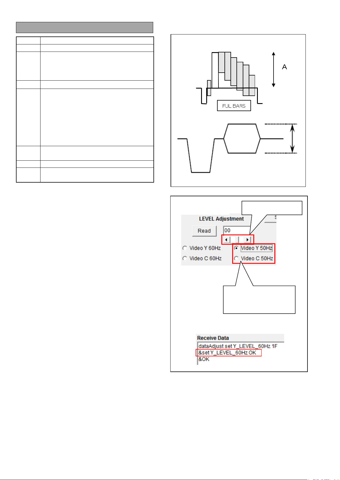
2-13. VBS Level Adjust (50Hz)
Video Y (50HZ)
ADJ.
MENU
Video C (50Hz)
LEVEL Adjustment scroll button
BARS (SMPTE)
Main Menu -> SYSTEM MODE
-> LINE&FREQ : 1080-50i
Main Menu -> OUTPUT SEL
->VIDEO OUT : ON
Main Menu -> SW MODE
B
SW
SPEC.
1. Press MENU button for 3 seconds to open Main Menu.
2. Set “VIDEO OUT” to “ON” (Main MENU > OUTPUT
3. Set “BARS TYPE” to “FULL BARS” (Main MENU >
4. Press the “BARS” button to output Color Bars.
5. Start PC EVR software “VVS0114”.
6. Connect a WFM to VIDEO OUT connector.
7. Input a check mark in “Video Y (50Hz)” and adjust the
8. Input a check mark in “Video C (50Hz)” and adjust the
When “&set Y_LEVEL_50Hz OK” or “&set
C_LEVEL_50Hz OK” is displayed in Receive Data window,
the setting is successful .
IN / OUT : OUT
A = 700mVp-p ± 7mV (50i)
SEL > VIDEO OUT).
SW MODE > BARS TYPE).
LEVEL Adjustment scroll button on EVR software so
that the level “A” becomes 700mVp-p ± 7mV.
LEVEL Adjustment scroll button on EVR software so
that the level “B” becomes 300mVp-p ± 3mV.
Adjustment button
Input a check mar k in the
adjustment item
ELE-32
Page 34

BOARD
MAIN Board
(75 ohm terminated)
WFM
vector display mode
(PC EVR software)
CHART
---
Setting
Signal Generator
74.175824MHz +/- 8Hz (59.94i)
Adjustment value display
Adjustment button
EVR software
Temperature
2-14. INT Clock Frequency
Adjustment
TP
ADJ.
MENU
SW
M. EQ.
HD SDI OUT
< MOS Temperature >
< VCXO Adjustment >
Adjustment button
Main Menu -> OUTPUT SEL -> SDI OUT : ON
BARS button : ON
HD SDI Waveform Monitor
SPEC.
74.250000MHz +/- 8Hz (50i)
1. Connect the WFM to the HD SDI OUT with 75ohm
termination.
2. Input a HD reference signal of the Signal Generator to
EXT IN of WFM.
3. Set to EXT reference mode on WFM.
4. Set to vector scope display mode on WFM.
5. Start PC EVR software “VVS0114”.
6. Measure MOS temperature by clicking “MOS
Temperature” button on EVR Software.
When the temperature is 42 degree or more, execute
the next adjustment.
If the temperature is 41 degree or less, keep camera
with the power supply switched on until the temperature
becomes 42 degree or more.
7. Set the adjustment value with “Adjustment button” of
VCXO Adjustment on EVR software so that the
rotation of the vector becomes very slowly..
When “&set 27M_VCXO OK” is displayed in Receive Data
window, the setting is successful
Note : The rotation of the vector does not stop completely.
Set the adjustment value to the point that the rotation
direction changes.
Adjust with one of 50i or 59.94i. It is not nec essary to
adjust with another System Frequency.
ELE-33
Page 35

BOARD
LCD unit
TP
LCD display
WFM
---
(PC EVR software)
CHART
---
Setting
M. EQ.
---
SPEC.
BOARD
HANDLE Unit / MAIN Board
TP
LCD Monitor
WFM
(PC EVR software)
CHART
---
Setting
M. EQ.
SPEC.
Horizontal setting = within ±1.4 degree
Set button
EVR software
Adjustment button
Adjustment value
EVR software
2-15. LCD Back Light Adjustment
2-16. LEVEL Gauge Adjustment
< LCD BL Adjustment >
Adjustment button
ADJ.
MENU
SW
Set button
Main Menu -> DISPLAY SETUP -> LCD
SETTING -> LCD BACKLIGHT
---
1. Press MENU button for 3 seconds to open Main Menu.
2. Set “LCD BACKLIGHT” to “-3” (Main MENU >
DISPLAY SETUP > LCD SETTING > BACKLIGHT).
3. Start PC EVR software “VVS0114”.
4. Set the adjustment value to “1FF” with “Adjustment
button” of LCD BL Adjustment on EVR software.
5. If LCD display is lighting on, click “Set” button on EVR
software to register the adjustment value.
6. If LCD display is no lighting, decrease the adjustment
value with “Adjustment button” of LCD BL
Adjustment on EVR software and find the value that
LCD display lights on.
7. Click “Set” button on EVR software to register the
adjustment value.
8. Return “LCD BACKLIGHT” to “0” (Main MENU >
DISPLAY SETUP > LCD SETTING > BACKLIGHT).
When “&set LCD_BL_0 OK” is displayed in Receive
Data window while adjusting, the setting is successful.
display
< LEVEL Gauge Adjust >
ADJ.
MENU
SW
Execute button
Main Menu -> DISPLAY SETUP -> LEVEL
GAUGE : ON
1. Set the Camera horizontally.
2. Set “LEVEL GAUGE” to “ON” (Main MENU >
DISPLAY SETUP > LEVEL GAUGE).
3. Start PC EVR software “VVS0114”.
4. Click “Execute button” of LEVEL GAUGE Adjust on
EVR software. The adjustment is automatically
executed.
When “&set LEVEL_GAUGE OK” is displayed in
Receive Data window, the adjusting is completed.
When “&set LEVEL_GAUGE NG” is displayed in
Receive Data window, re-adjust again.
5. Confirm the green line is indicated when no
inclinations. And when camera is inclined, confirm
the yellow lines is displayed.
ELE-34
Page 36

BOARD
HANDLE unit / MAIN Board
TP WFM
---
(PC EVR software)
CHART
---
-> OUTPUT SETTING -> TEST TONE : ON
AUDIO MON/ADV but ton : Center(13)
M. EQ.
---
SPEC.
EVR software
T (Japan)
P,EJ,EN,AN,PX,MC
2-17. MIC Balance Adjustment
2-18. Time / Zoon Sett ing
< MIC Balance Adjust >
ADJ.
MENU
SW
Setting
Execute button
Main Menu -> AUDIO SETUP
-> INPUT S ETTING -> INT MIC : STEREO
->
RECORDING CH SETTING -> HEADROOM : 20dB
-> OUTPUT SETTING -> AUDIO OUT : CH1/ CH2
INPUT1/INPUT2 SW(LINE/MIC/M+48) : LINE
CH1 SELECT/CH2 SELECT SW(INT/INPUT1/INPUT2)
:
INT(L) / INT(R)
CH1/CH2 SW(AUTO/MANUAL) : MANUAL
AUDIO LEVE L CH1/ CH2 dial : Center
F.AUDIO LE V EL dial : MAX(10)
1. Set MENU and Switch settings as mentioned above.
2. Set Camera under very low noise.
3. Start PC EVR software “VVS0114”.
4. Click “Execute” button of “MIC Balance Adjust” on
EVR software. The adjustment is automatically
executed.
When “&set INT_MIC_LEVEL OK” is displayed in
Receive Data window, the adjusting is completed.
When “&set INT_MIC_LEVEL NG” is displayed in
Receive Data window, re-adjust again.
1. Set Camera to “COM” mode and connect to PC with
USB cable.
2. Start PC EVR software “VVS0114”.
3. Click “Time / Zoon setting” button on EVR Software.
P, EJ, EN, AN, PX, MC model : G/EJ/MC button
T(Japan) model : T(Japan) button
ELE-35
Page 37

BOARD
LENS Unit / MAIN Board
(75 ohm terminated)
WFM
YPbPr display mode
ADJ.
---
CHART
White Chart
KNEE MODE : OFF
FOCUS : not focusing
HD Monitor TV
SPEC.
Black shoot level is less than 20% (140mV).
BOARD
LENS Unit / MAIN Board
(75 ohm terminated)
WFM
Waveform / Vector display mode
ADJ.
---
CHART
White Chart
IRIS : F4.0
HD Monitor TV
and it locates at the zero point in the vector.
OK
OK
Vector scope
2-19. White Bl e m ish Confirmation
2-21. White Shading Confirmation
Please refer to “8-3-1 Blemish Confirmation” of Section 1.
2-20. Black Blemish Confirmation
TP
MENU
SW
Setting
M. EQ.
1. Press MENU button for 3 seconds to open Main Menu.
2. Set “LINE&FREQ” to “1080-59.94i” (Main MENU >
3. Set “SHOOTING MODE” to “HIGH SENS” (Main
4. Shoot the W hi te Chart under 3100K (2000 LUX).
5. Set the IRIS with IRIS Ring so that the White level of
6. Execute AWB with “AWB” SW of Camera.
7. Confirm that the White level of HD SDI OUT becomes
8. Confirm that the Black-shoot level is less than 20%
HD SDI OUT
Main Menu -> SYSTEM MODE
LINE&FREQ : 1080-59.94i
SHOOTING MODE : HIGH SENS
Main Menu -> SCENE FILE -> KNEE SETTING
Shutter : OFF(1/60)
Gain : L(0dB)
WHITE BAL : PRST(3200K)
ND Filter : OFF
HD Waveform Monitor,
SYSTEM MODE > LINE&FREQ).
MENU > SYSTEM MODE > SHOOTING MODE).
HD SDI OUT becomes to 70-90%.
to 70-90%.
(140mV) in all area.
TP
MENU
SW
Setting
M. EQ.
SPEC.
HD SDI OUT or VIDEO OUT
Main Menu -> SYSTEM MODE
LINE&FREQ : 1080-59.94i
Gain : L(0dB)
WHITE BAL : A
ZOOM : Z999
Waveform Monitor,
Vector scope,
Vector dot size is smaller than Shading OFF,
1. Shoot the W hi te Chart under 3100K.
2. Set Shutter so that White level becomes to 70 – 90%.
3. Execute AWB with White Balance SW “A” position.
4. Set Camera to “COM” mode and connect to PC with
USB cable.
5. Start PC EVR software “VVS0114”.
6. Click “OFF” of Shading button on EVR Software.
White Shading compensation becomes to OFF.
7. Confirm Vector dot size is smaller than Shading OFF,
and it locates at the zero point in the vector when
clicking “Release” of Shading button on EVR
Software.
ELE-36
 Loading...