

Page 1

DISASSEMBLY PROCEDURES
1. Disassembly Flowchart ............................................................................................................... DIS-1
2. Removal of GRIP Unit ................................................................................................................. DIS-2
3. Removal of JACK COVER REAR Unit ........................................................................................ DIS-4
4. Removal of SIDE CASE R Unit ................................................................................................... DIS-4
5. Removal of HANDLE Unit ........................................................................................................... DIS-6
6. Removal of POWER P. C. Board ................................................................................................ DIS-8
7. Removal of AUDIO P. C .Board .................................................................................................. DIS-9
8. Removal of L SIDE JACK Unit .................................................................................................... DIS-10
9. Removal of Main P. C. Board. ..................................................................................................... DIS-12
10. Removal of LENS Unit .............................................................................................................. DIS-13
11. Removal of EVF Unit. ................................................................................................................ DIS-15
12. Removal of LCD Unit. ................................................................................................................ DIS-16
Model No. : AJ-PX270/EJ, AJ-PX285MC,298MC
CONTENTS
Page 2
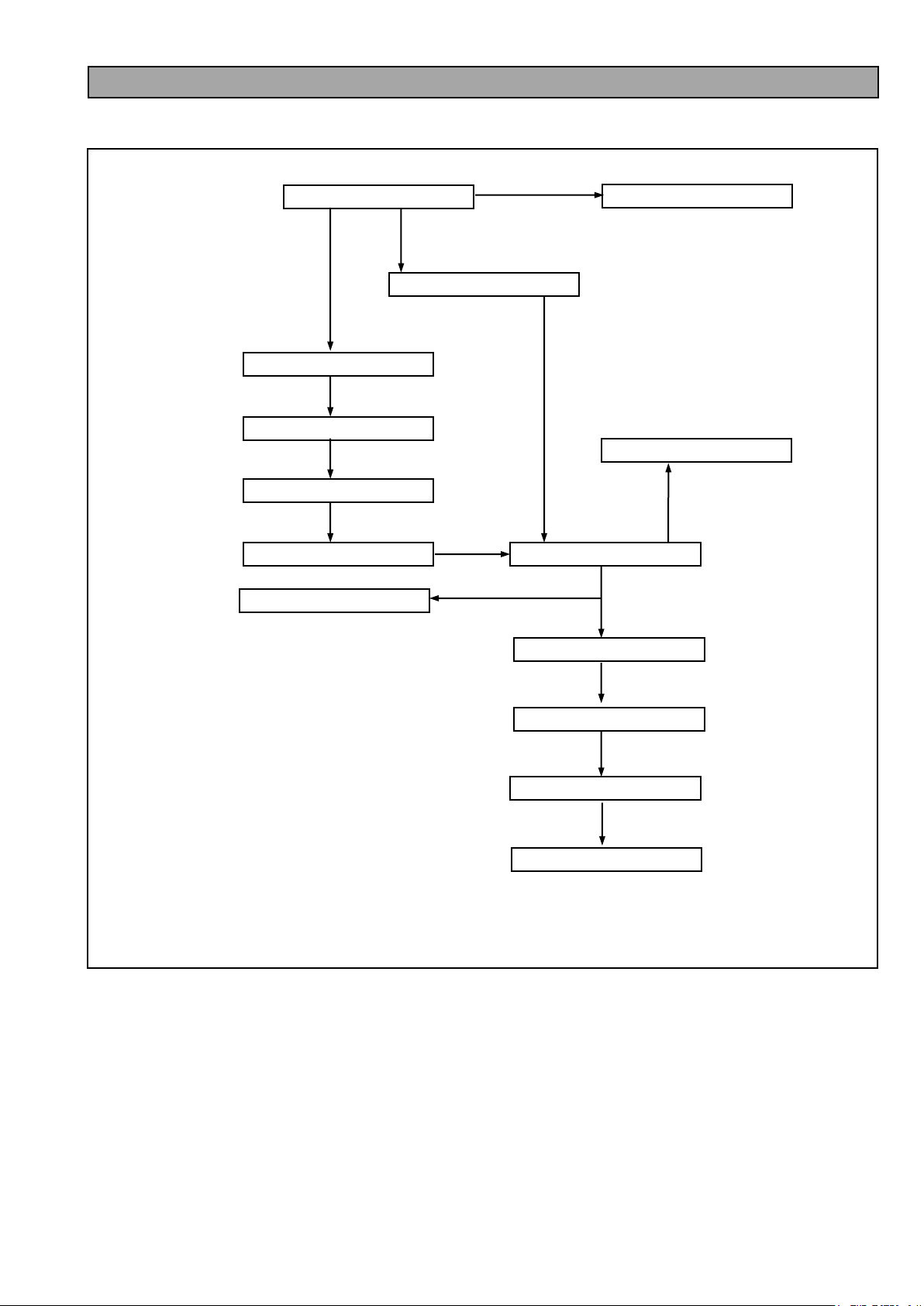
2. GRIP Unit
3. JACK COVER Unit
4. SIDE CASE R Unit
6. POWER P. C .Board
TOP SHIELD
DECORATION RING
5. HANDLE Unit
TOP COVER
7. AUDIO P. C. Board
8. L SIDE JACK Unit
11. EVF Unit
9. Main P. C .Board
10. Lens Unit
12. LCD Unit
1. Disassembly Flowchart
NOTE: Please put on your hand glove, when you operated disassemble and assemble.
DIS-1
Page 3
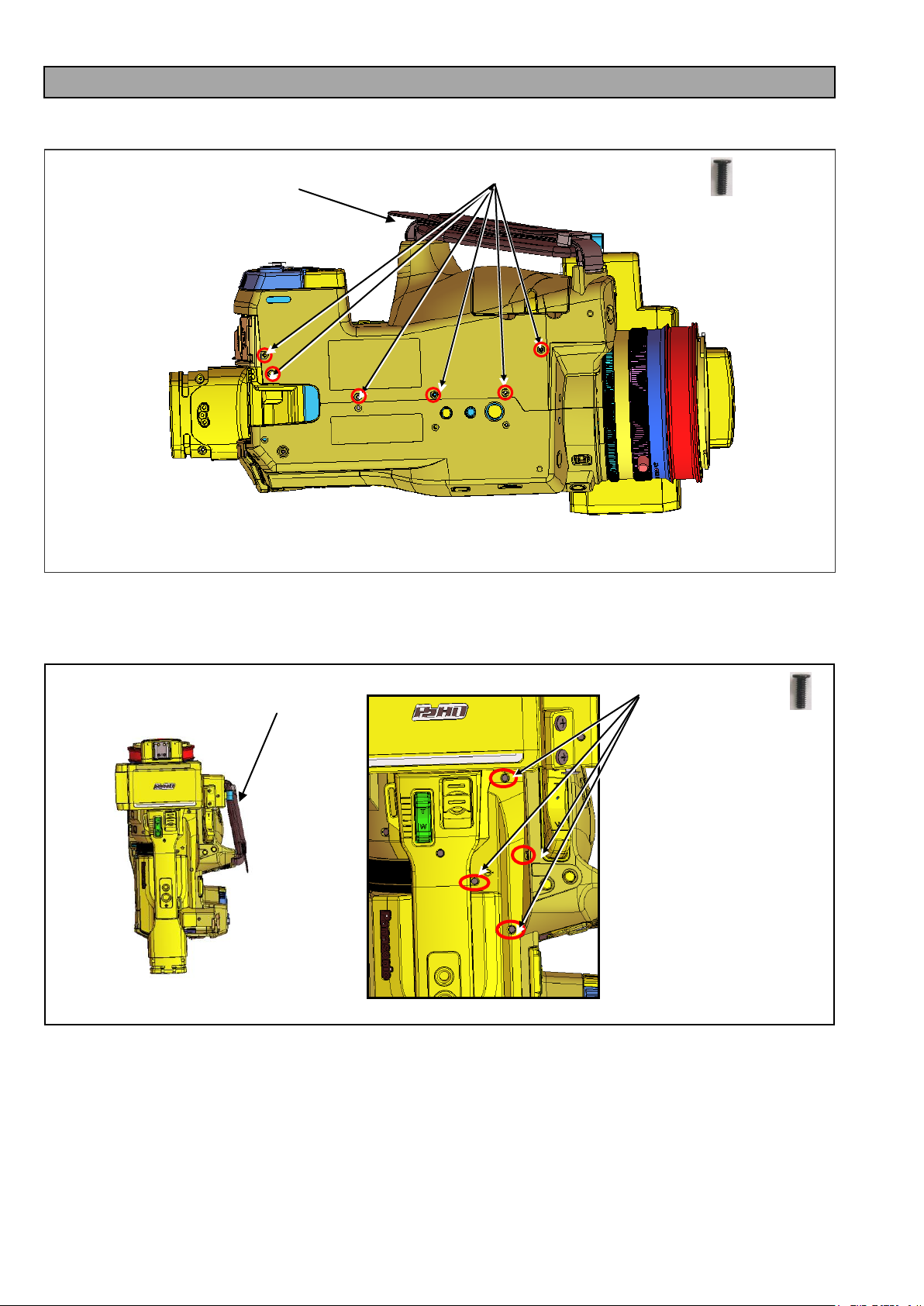
SCREW (A) XQN2+B5FJK
SCREW (B) XQN2+B5FJK
Grip Unit
Grip Unit
2. Removal of GRIP Unit
1. Unscrew 6 screws (A) as shown in figure 2-1.
2. Unscrew 4 screws (B) as shown in figure 2-2
Figure 2-1
Figure 2-2
DIS-2
Page 4
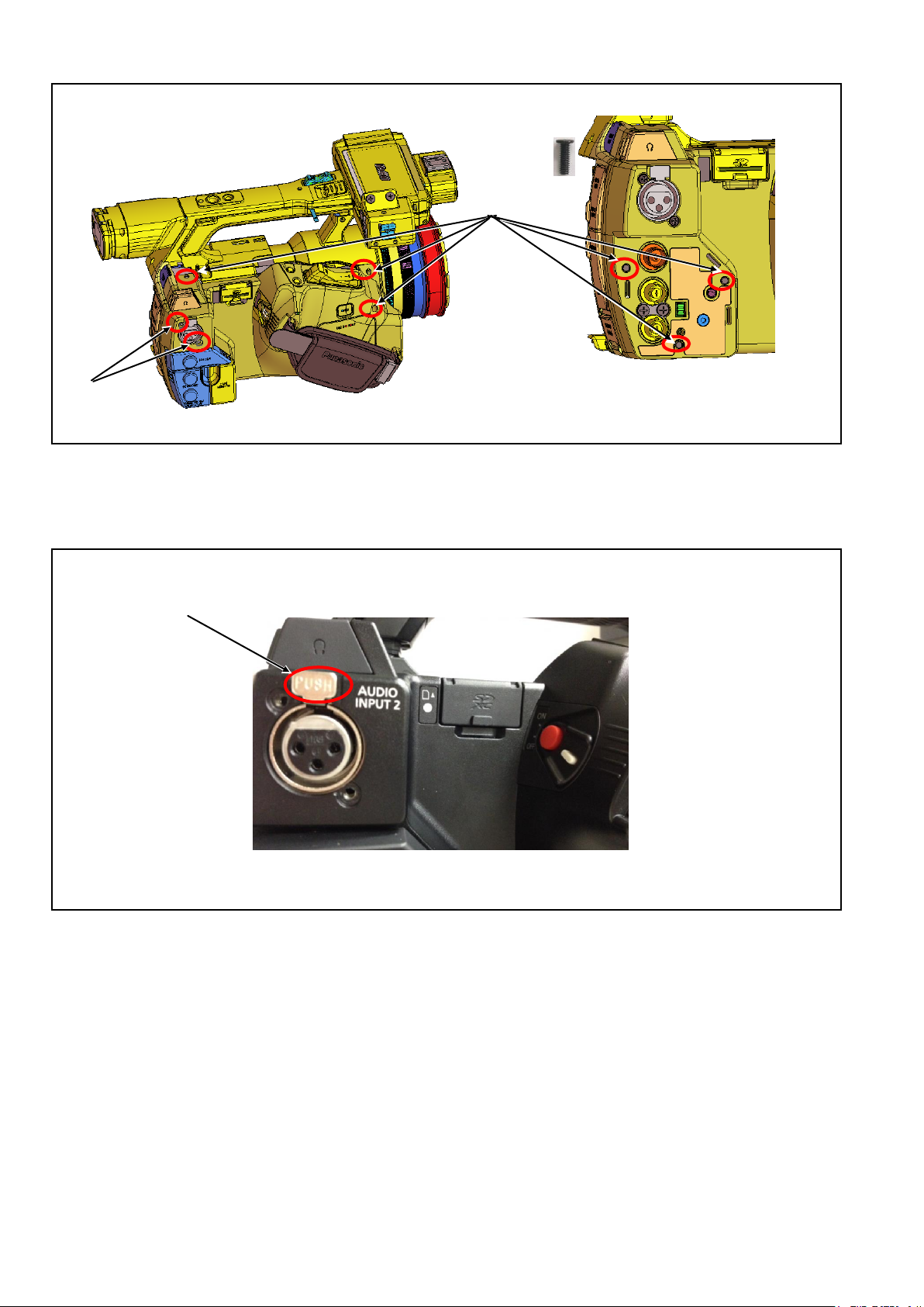
3. Unscrew 6 screws (C) and 2 screws (D) as shown in figure 2-2
SCREW (C)
XQN2+B5FJK
SCREW (D)
XYN26+A6FJK
Figure 2-3
4. Pull out “XLR PUSH pin” as shown in figure 2-4
5. Remove the Grip Unit.
Figure 2-4
DIS-3
Page 5
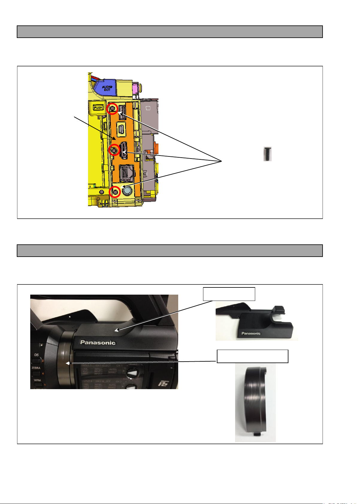
SCREW (A)
XQN2+B5FJK
TOP COVER
DECRATION RING
Jack Cover Unit
3. Removal of JACK COVER Unit
1. Remove the GRIP Unit
2. Unscrew 3 screws (A) as shown in figure 3-1
Figure 3-1
3. Remove Jack Cover Unit.
4. Removal of SIDE CASE R Unit
1. Remove the GRIP Unit.
2. Remove the TOP COVER and DECORATION RING
Figure 4-1
DIS-4
Page 6
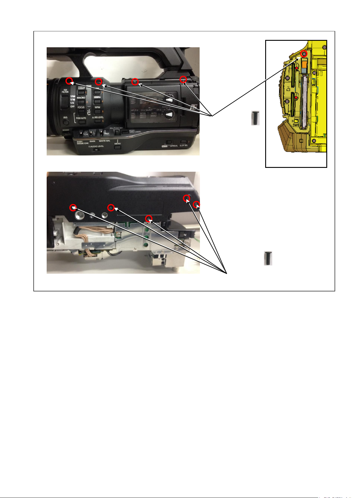
4. Unscrew 10 screws (A) as shown in Figure 4-2
SCREW (A)
XQN2+B5FJK
SCREW (A)
XQN2+B5FJK
4. Remove the Side Case R unit.
Figure 4-2
DIS-5
Page 7

SCREW (A)
XQN2+B5FJK
SCREW (B)
XYN3+J10FJ
SCREW (D)
XQN2+B4FN
*NOTE: When assembling, please make sure that the edge of TOP SHIELD
circled in blue is inside the MAIN FRAME and MAIN SHIELD.
Handle Unit
SCREW (C)
XQN26+A6FJK
5. Removal of HANDLE Unit
1. Remove the GRIP Unit
2. Remove the TOP COVER and DECORATION RING
3. Remove the SIDE CASE R Unit
4. Unscrew screw (A) , screw (B) and 2 screws (C) as shown in figure 5-1.
Figure 5-1
5. Remove the TOP SHIELD.
6. Unscrew 3 screws (D) as shown in figure 5-2
Figure 5-2
DIS-6
Page 8

Note: When reassembling HADLE Unit please make sure that the EVF cable is positioned as shown in Figure 5-3
EVF Unit should be set to horizontal
position when reassembling.
EVF cable should be positioned between
HANDLE COVER L and the AUDIO
HADLE COVER L
EVF cable should be positioned
above the
EVF cable should pass through the
groove of Main P.C.Board.
Figure 5-3
DIS-7
Page 9

6. Removal of POWER P. C. Board
CONNECTOR (A)
The position of TAPE
SCREW (A)
XQN2+B4FN
CONNECTOR (B)
1. Remove the GRIP Unit
2. Unscrew 7 screws (A) as shown in figure 6-1 and remove the POWER SUB PCB
Figure 6-1
3. Disconnect the CONNECTOR (A) and the CONNECTOR (B) as shown in figure 6-2.
Figure 6-2
DIS-8
Page 10

SCREW (A)
XQN2+B4FN
AUIDO P. C. Board
When disconnecting the cable,
please unlock the lock lever.
CABLE(A)
CABLE(B)
7. Removal of AUDIO P. C .Board
1. Remove the GRIP Unit
2. Remove the TOP COVER and DECORATION RING
3. Remove the SIDE CASE R Unit
4. Remove the TOP SHIELD
5. Remove the HANDLE Unit
6. Unscrew 2 screws (A) and disconnect cable (A) and (B)
Figure 7-1
NOTE: When reassembling please make that AUDIO P. C .Board FRAME is fixed in the correct position
without distortion as shown in figure 7-2.
Figure 7-2
DIS-9
Page 11

8. Removal of L SIDE JACK Unit
SCREW (A)
XQN2+B4FN
BOTTOM SHIELD
SCREW (B)
XQN2+B4FN
SCREW (C)
VHD2057
SCREW (B)
XQN2+B4FN
CABLE(A)
CABLE(B)
1. Remove the GRIP Unit
2. Remove the TOP COVER and DECORATION RING
3. Remove the SIDE CASE R Unit
4. Remove the TOP SHIELD
5. Remove the HANDLE Unit
6. Remove the AUDIO P. C. Board
7. Unscrew 6 screws (A) and disconnect the BOTTOM SHIELD as shown in figure 8-1
Figure 8-1
8. Unscrew 5 screws (B) and screw (C) as shown in figure 8-2.
9. Disconnect the cable (A) and (B)
Figure 8-2
DIS-10
Page 12

NOTE: When reassembling please make that the L SIDE JACK Unit is fixed in the correct position as shown
Upper side of L SIDE JACK U
Back case side of L SIDE JACK U
Bottom side of L SIDE JACK U
L Side Jack Shield should be
inside the Main Frame shield.
L Side Jack Shield should be
inside the Main Frame shield.
Please make sure that the claw of L Side
Jack Shield is properly fixed.
L Side Jack Frame should be
upside the Main Frame Shield.
in figure 8-3.
Figure 8-3
DIS-11
Page 13

9. Removal of Main P. C. Board
SCREW (A)
XQN2+B4FN
SCREW (C)
XQN2+B4FN
G R B
CONNECTOR (A)
CABLE (B)
CABLE (C)
SCREW (B)
XQN2+B4FN
Bottom View
1. Remove the GRIP Unit
2. Remove the JACK COVER Unit
3. Remove the TOP COVER and DECORATION RING
4. Remove the SIDE CASE R Unit
5. Remove the TOP SHIELD
6. Remove the HANDLE Unit
7. Remove the AUDIO P. C. Board
8. Remove the L SIDE JACK Unit
9. Remove the BOTTOM SHILED.
10. Unscrew screw (A), screw (B) and remove the DC IN P.C.BOARD as shown in figure 9-1
Figure 9-1
11. Unscrew 4 screws (C) and disconnect the connector (A), cable (B) and (C)
Figure 9-2
DIS-12
Page 14

Note: When reassembling please make sure that the cable (C) is fixed as shown in figure 9-3
CONNECTOR (B)
CABLE (C)
SCREW (A)
XQN2+B4FN
CABLE Layout
CABLE Layout
MOS Sensor Shield
Figure 9-3
10. Removal of LENS Unit
1. Remove the GRIP Unit
2. Remove the TOP COVER and DECORATION RING
3. Remove the SIDE CASE R Unit
4. Remove the TOP SHIELD
5. Remove the HANDLE Unit
6. Remove the AUDIO P. C. Board
7. Remove the BOTTOM SHIELD
8. Remove the MAIN P. C. Board
9. Unscrew 3 screws (A) and remove the MOS SENSOR SHIELD.
Figure 10-1
DIS-13
Page 15

9. Unscrew 5 screws (B) and remove the TOP P. C. Board as shown in figure10-2
SCREW (B)
XQN2+B4FN
SCREW (C)
XYN3+J10F
Figure 10-2
10. Unscrew 3 screws (C) as shown in figure10-3
Figure 10-3
Note: When reassembling please make sure that the MOS sensor cable is positioned as shown in figure 10-4.
Figure 10-4
DIS-14
Page 16

11. Removal of EVF Unit
CABLE (A)
SCREW (B)
XQN2+B5FJK
Handle Top Unit
SCREW (A)
XQN2+B5FJK
Note: Slide switch is set to OFF position.
Handle BACK COVER
1. Remove the GRIP Unit
2. Remove the TOP COVER and DECORATION RING
3. Remove the SIDE CASE R Unit
4. Remove the TOP SHIELD
5. Remove the HANDLE Unit
6. Unscrew 7 screws (A) , disconnect cable (A) and remove HANDLE TOP Unit and HANDLE BACK COVER
as shown in figure 11-1
7 .Unscrew 2 screws (A) as shown in figure 11-2
Figure 11-1
Figure 11-2
DIS-15
Page 17

Note: When reassembling please make sure that the cable of EVF unit is positioned as follows
SCREW (B)
XSB4+6FJK
SCREW (C)
XSB4+6FJK
SCREW (A)
XQN2+B5FJK
Note: Please be careful of EVF cable position
unless EVF cable may be damaged
before assembling the HANDLE BACK COVER.
Figure11-3
12. Removal of LCD Unit
1. Remove the GRIP Unit
2. Remove the TOP COVER and DECORATION RING
3. Remove the SIDE CASE R Unit
4. Remove the TOP SHIELD
5. Remove the HANDLE Unit
6. Remove HANDLE TOP Unit
7. Unscrew 1 screw (A), 2 screws (B) and 4 screws (C) as shown in figure 12-1
Figure 12-1
DIS-16
Page 18

8. Unscrew 5 screws (D) , 2 screws (E) and disconnect XLR “PUSH” pin as shown in figure 12-2
SCREW (D)
XQN2+B5FJK
SCREW (D)
XQN2+B5FJK
SCREW (E)
XYN26+A6FJK
SCREW (E)
XQN26+A6FJK
Note: Please make sure that those two cables are
under the P. C .Board when reassembling.
Note: Please make sure that those two cables are
positioned along the frame of HANDLE Unit.
Figure12-2
9. Unscrew 2 screws (E) as shown in figure 12-3
Note: When reassembling the LCD Unit, please make sure that the two cables of LCD Unit are positioned as
shown in figure 12-4
Figure12-3
Figure12-4
DIS-17
 Loading...