

Page 1

SERVICE INFORMATION
CONTENTS
1. Service Fixture & Tools ................................................................................................................ INF-1
1-1. List of Service Fixture and Tools ........................................................................................... INF-1
1-2. List of Recommended Measuring and Instruments ............................................................... INF-2
2. Maintenance ................................................................................................................................. INF-3
2-1.Maintenance Schedule ........................................................................................................... INF-3
2-2. Confirmation method of operation number of times of the Zoom Motor ............................... INF-3
2-3. Reset of operation number of times of the Zoom Motor ....................................................... INF-3
2-4. Replacement procedure of Zoom Motor unit ......................................................................... INF-3
3. Replacement procedure of Lithium Battery .................................................................................. INF-4
4. Basic Setting Menu Operations .................................................................................................... INF-5
4-1. Construction of Menu ............................................................................................................ INF-5
4-2. Service Menu Operation ........................................................................................................ INF-5
4-3. ENG Security ......................................................................................................................... INF-5
5. SERVICE MENU .......................................................................................................................... INF-6
5-1. SERVICE MENU screen ....................................................................................................... INF-6
5-2. Making of Service SD memory card ...................................................................................... INF-9
5-3. LOG..... .................................................................................................................................. INF-9
6. Software update procedure .......................................................................................................... INF-10
6-1. MICROCOMPUTER / FPGA CHART ................................................................................... INF-10
6-2. Version display method (SERVICE MENU) .......................................................................... INF-11
6-3. Version display method (MAIN MENU) ................................................................................. INF-11
6-4. Update with the SD memory card ......................................................................................... INF-12
6-4-1. Preparation of update ................................................................................................. INF-12
6-4-2. Updated procedure ..................................................................................................... INF-13
Model No. : AJ-PX270/EJ, AJ-PX285MC,298MC
Page 2

7. PC EVR software ......................................................................................................................... INF-16
7-1. Required tools and equipment for PC EVR software............................................................ INF-16
7-2. Setup……… .......................................................................................................................... INF-16
7-2-1. Installation method of USB driver ............................................................................... INF-16
7-3. Setup of PC EVR software .................................................................................................... INF-19
7-4. Function of PC EVR software ............................................................................................... INF-20
8. Data Backup Procedure ............................................................................................................... INF-35
8-1. Setup…. ................................................................................................................................ INF-35
8-2. Back Up Procedure ............................................................................................................... INF-36
8-2-1. CAM EEPROM Dump……………………………………………………………………..INF-36
8-2-2. BE Data Backup……………………………………………………………………………INF-37
8-3. Backup Data Writing Procedure ........................................................................................... INF-37
8-3-1. CAM EEPROM Writing Procedure……………………………………………………….INF-37
8-3-2. BE Data Writing Procedure……………………………………………………………….INF-38
9. White Blemish Compensation ...................................................................................................... INF-39
9-1. Blemish Compensation flow .................................................................................................. INF-39
9-2. Connection ............................................................................................................................ INF-39
9-3. Blemish Compensation Procedures ..................................................................................... INF-40
9-3-1. Blemish confirmation .................................................................................................. INF-40
9-3-2. Manual compensation procedure ............................................................................... INF-41
9-4. Remarks ................................................................................................................................ INF-42
9-4-1. Delete registered data one by one ............................................................................. INF-42
9-4-2. Change Parameter about blemish compensation ...................................................... INF-42
9-4-3. About the position inhibited to register the compensation data.................................. INF-42
10. Operation after major part exchanged ....................................................................................... INF-43
10-1. Operation List .................................................................................................................... INF-43
10-2. Operation flow chart after replacement of major parts ...................................................... INF-44
10-2-1. MAIN P.C.Board. .................................................................................................. INF-44
10-2-2. LENS Unit ............................................................................................................. INF-47
10-2-3. LCD Unit / MONITOR P.C.Board. ......................................................................... INF-47
10-2-4. BATTERY R Unit / BATTERY P.C.Board. ............................................................ INF-48
10-2-5. GRIP Unit / ZOOM SW P.C.Board. ...................................................................... INF-48
10-2-6. HANDLE Unit / HANDLE OP P.C.Board. ............................................................. INF-48
10-2-7. INT MIC. ................................................................................................................ INF-49
10-3. Adjustment after replacement of major parts .................................................................... INF-50
11. P.C.Board Location .................................................................................................................... INF-51
Page 3

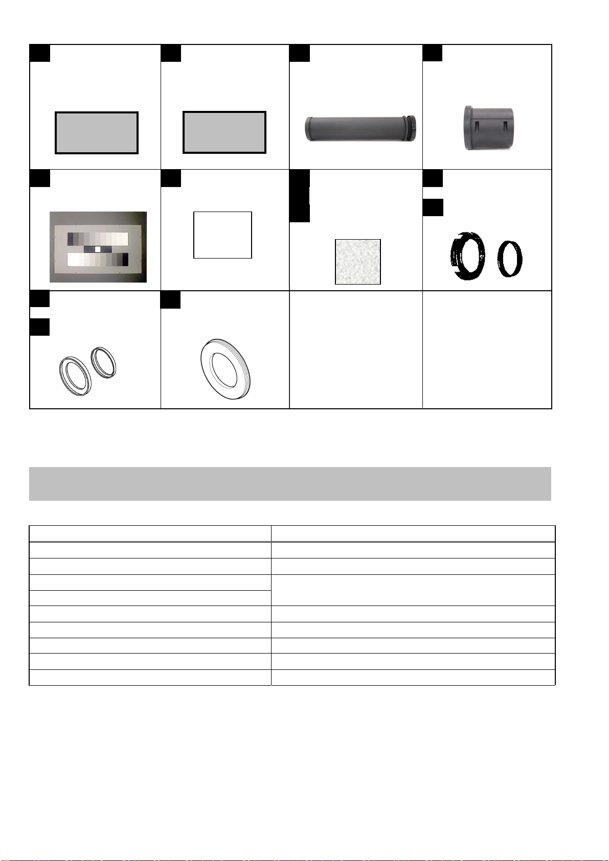
1. Service Fixture & Tools
1-1. List of Service Fixture and Tools
No. Parts No. Name Remarks
1 VVS0114 PC EVR Software for AG-PX270 series Download from Global Service WEB Site
2 VSI5386B USB Driver for EVR Adjustment Download from Global Service WEB Site
3 RFKZ0422 Collimator
4 ---------- Collimator Adaptor
5 VFK1642
6 --------- White chart
7 VFK1347 CC Filter (LB120)
8 VFK1884 CC Filter (LBA2)
9 VFK1888 CC Filter (LBB6)
10 VFK1345 CC Filter Holder
11 VFK1346 Step-Down Ring (62mm-52mm)
12 VFK1659 Step-Up Ring (43mm-49mm)
13 VFK1660 Step-Up Ring (49mm-62mm)
14 VFK1809 72mm Attachment Ring
Gray Scale Chart (Reflection type) 16:9
*NOTE1:
The AG-HMC150/HPX170 series is used. Please consult service department of Professional AV Business unit
about purchase. It is the same as the service tool used by serving the Digital Still Camera.
*NOTE2:
The AG-HMC150/HPX170 series is used. Please consult service department of Professional AV Business unit
about purchase.
*NOTE1: Please refer to the following.
*NOTE2: Please refer to the following.
INF-1
Page 4
V
A
V
VS0114
1 2
PC EVR Software for
G-PX270 series
USB Driver
for EVR Adjustment
SI5386B
DOWN LOAD
DOWN LOAD
VFK1642
5 6 7
Gray-scale Chart
(16:9, Reflection Type)
-----
White Chart
VFK1659
12
Step-up Ring (43mm - 49mm)
VFK1660
13
Step-up Ring (49mm - 62mm)
VFK1809
14
72 mm Attachment Ring
VFK1660
VFK1659
RFKZ0422
3
Collimator
VFK1347 (LB120)
VFK1884 (LBA2)
8
VFK1888 (LBB6)
9
CC Filter
-----
4
Collimator Adaptor
10
VFK1345
CC Filter Holder
VFK1346
11
Step Down Ring
VFK1345 VFK1346
(62mm - 52mm)
1-2. List of Recommended Measuring and Instruments
NAME REMA RKS
HD Monitor TV with SDI input
Monitor TV
HD/SD Waveform Monitor
Vector Scope
Halogen Lamp 500W 3200K
Lux Meter
Color Pyrometer
with SDI INPUT
R,G,B/Y,Pb,Pr Display Switching
INF-2
Page 5
2. Maintenance
2-1. Maintenance Schedule
No. Part Name Part No. Pcs Replacement
1 Zoom Motor Unit L6DAYYYC0001 1 Every 50,000 number of times (SERVO ZOOM)
*
Please refer to the following procedures.
The maintenance execution time shown in the above is recommendation for standard maintenance execution.
This is not life of various parts. The life is influenced by temperature, humidity, dust, etc..
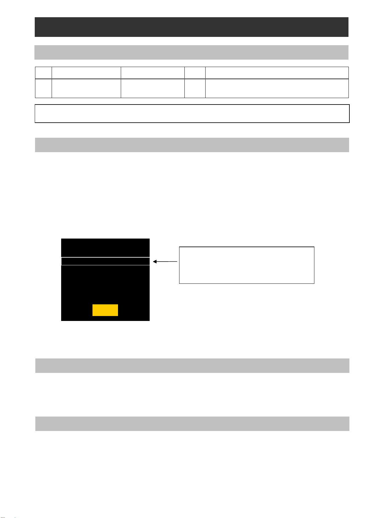
2-2. Confirmation method of operation number of times of the Zoom Motor
The operation number of times of Zoom Motor is displayed on item SERVICE INFO in SERVICE menu screen.
1. Confirm that the camera recorder is set to CAMERA mode.
2. Push the button in order of “SHIFT” button → “STOP” button → “Control stick RIGHT”→ “RESET” button
→ “MENU” button. SERVICE menu (P2 CS SERVICE, DEFECT(SETTING) and DEFECT(EDIT)) will be
displayed.
3. Select “P2 CS SERVICE” with Control stick ( ▲ or ▼ direction ) and press SET(Control stick) button.
4. Select “SERVICE INFO” with Control stick ( ▲ or ▼ direction ) and press SET(Control stick) button.
SERVICE INFO menu opens.
5. The operation number of times of Zoom Motor is displayed on item SERVO ZOOM in SERVICE INFO menu
screen.
The operation number of times can be confirmed also with the PC EVR software. Please refer to item “5. Hour
Meter information” of “7-4. Function of EVR software” about display procedure with PC EVR software.
OPERATION : 474h
P.ON TIMES : 464
SERVO ZOOM : 800
GRIP ZOOM : 500
HANDLE ZOOM : 100
LCD OPERATION : 420h
EVF OPERATION : 16h
OK
The operation number of times of the zoom
motor of the lens unit is displayed.
NOTE: The display times is updated by every
100 times.
2-3. Reset of operation number of times of the Zoom Motor
After replacing Zoom Motor unit, set the operation number of times to 0 times.
Please refer to item “6. Hour Meter Reset” of “7-4. Function of EVR software” about setting procedure with PC
EVR software.
2-4. Replacement procedure of Zoom Motor unit
The removal procedure has been described to the item “16. Removal of ZOOM MOTOR Unit” of disassembly
procedure (SECTION 2).
INF-3
Page 6
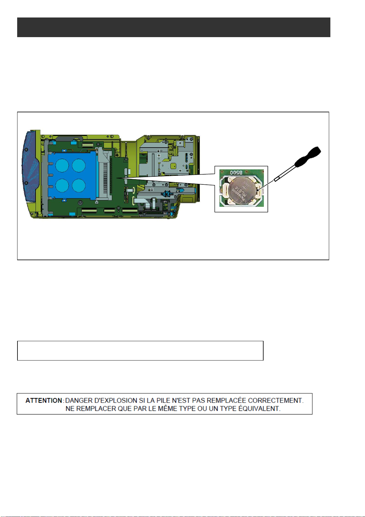
3. Replacement procedure of Lithium Battery
1. Remove the SIDE CASE R S U “VYK6S74”.
2. There is a Lithium battery on the P2 card P.C.B “VEP23724A” (Ref No: ETC100 at foil side of P2 card P.C.B.).
3. Insert the screwdriver to groove of the Lithium Battery Holder and press down it to remove the Lithium Battery.
(Pay attention for remove of battery to be pop-up)
4. Install the new battery.
5. Set the date and time of internal clock (Refer to item “Setting the date/time of the internal clock” of
operation instructions for the setting method).
NOTE: The date and time of internal clock can be set also with PC EVR software. Please refer to item “<4.
Time / Zone setting>” in “7-4. Function of PC EVR Software”.
Insert the screwdriver to
remove the Lithium Battery.
Lithium Battery
Type: ML614S
NOTE:
The lithium battery is a critical component.
It must never be subjected to excessive heat of discharge.
It must therefore only be fitted in equipment designed specifically for its use.
Replacement batteries must be of the same type and manufacture.
They must be fitted in the same manner and location as the original battery, with the correct polarity contacts
observed.
Do not attempt to re-charge the old battery or re-use it for any other purpose.
It should be disposed of in waste products destined for burial rather than incineration.
CAUTION: DANGER OF EXPLOSION IF BATTERY IS INCORRECTLY REPLACED.
REPLACE ONLY WITH THE SAME OR EQUIVALENT TYPE.
INF-4
Page 7
SERVICE MENU
P2 CS SERVICE
DEFECT (SETTING)
DEFECT (EDIT)
4. Basic Setting Menu Operations
MENU
Menu Type
How to open
User menu
Press the <MENU> button
Main menu
Press and hold the <MENU>
button for 3 seconds or more.
Option menu
Press the <MENU> button while
BACKLIGHT> button.
Please refer to item “5. SERVICE Menu”
about contents of the SERVICE menu.
These menu is mentioned
Press <SHIFT> -> <STOP> -> <Control stick RIGHT> -> <RESET> -> <MENU> button in order.
to open the function.
STOP
SHIFT
Control stick
RESET
MENU
4-1. Construction of Menu
pressing and holding the <LCD
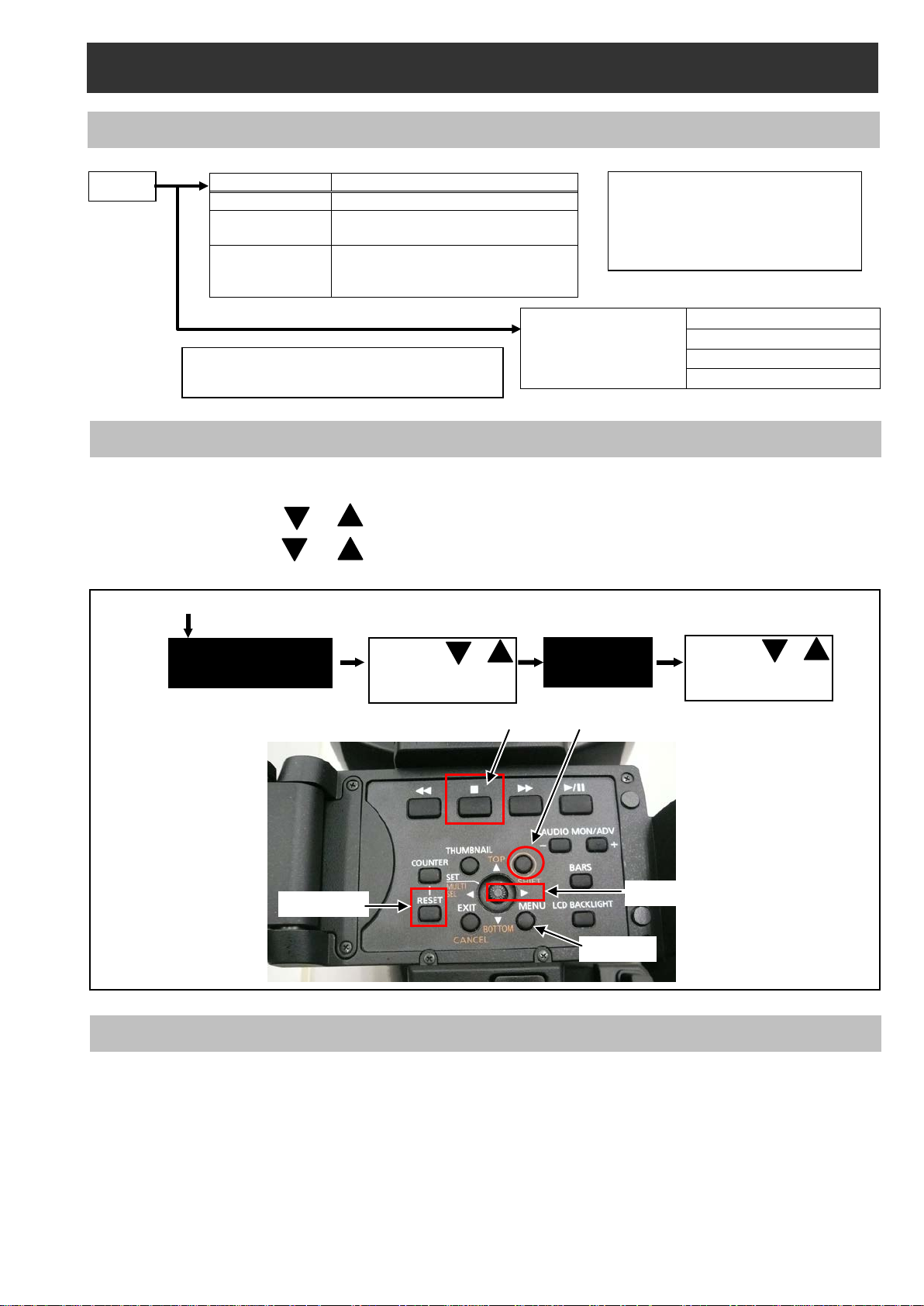
4-2. Service Menu Operation
1. Press <SHIFT> -> <STOP> -> <Control stick RIGHT> -> <RESET> -> <MENU> button in order.
SERVICE MENU is displayed.
2. Press the Control st ick or to select each Item . And then press “SET(Control stick)” button to op en
the selected SUB menu.
3. Press the Cont rol stick or to select th e item in SUB m enu. And then press “SET(Control stick)”
button to open SUB menu function.
SERVICE MENU
Select with or
Press “SET” button.
SUB MENU
in the Operating Instructions.
Select with or
Press “SET” button
4-3. ENG Security
When “ENG SECURITY” in OPTION MENU is set to “ON”, all menus can not be opened except for “USE R MENU”.
The following procedure allows you to temporarily remove the restriction on displaying menus.
1. Turn the power to “ON” while pressing “AWB” button (on the front) and “REC CHECK” button (on the grip)
simultaneously. The restriction is temporarily removed.
2. Open “OPTION MENU” by pressing “MENU” button while pressing “LCD BACKLIGHT” button.
3. Set “ENG SECURITY” to “OFF”.
INF-5
Page 8

5. SERVICE MENU
The items shown in gray are used in the electrical adjustments
5-1. SERVICE MENU screen
[ P2CS SERVICE ]
This menu is used for version confirmation or LOG saving.
ITEM RANGE & SET VALUE PRESET Setting contents and outline function explanation
VERSION
P2CS BL 1
P2CS BL 2-1
P2CS BL 2-2
P2CS KR
P2CS AP
VUP
VERSION
SERVICE INFO
EXTERNAL YES / NO NO
LOG*
MACHINE CHECKSUM
VUP FS
SYSCON
SYS BOOT
SYS FONT
CODEC SOFT
CODEC IPL
AVIO FPGA
CAM EEPROM
OPERATION Total operation time (hour meter)
P.ON TIMES The number of times of Power ON
SERVO ZOOM
GRIP ZOOM The number of times of Grip Zoom s witch
HANDLE ZOOM The number of times of Handle Zoom switch
LCD OPERATION LCD operation time (hour meter)
EVF OPERATION EVF operation time (hour met er)
MEMORY TO SD
FILE TO SD
P2CS BL 1
P2CS BL 2-1
P2CS BL 2-2
P2CS KR
P2CS AP
VUP
VUP FS
SYSCON
SYS BOOT
CODEC SOFT
CODEC IPL
AVIO FPGA
----
---
.
All software version is displayed.
Pressing right cursor button or left cursor button, next
page is displayed.
The number of times of Zoom motor (Wide <-> Tele back
and forward)
This menu is only use at factory.
Please do not execute it.
LOG data can be written on the SD memory card.
MEMORY TO SD:
The LOG data is transfer to SD card from FLASH
ROM (IP3900) on MAIN board (included error log).
FILE TO SD:
The LOG data is transfer to SD memory card from
PQ MICON (IC3800) on MAIN board.
* In order to save LOG to SD card,
it is necessary to make a service SD card.
The checksum of the each installed software can
be confirmed.
INF-6
Page 9

P2CS BL 1
P2CS BL 2-1
P2CS BL 2-2
P2CS KR
P2CS AP
IMAGE CHECKSUM
LCD SUB BRIGHT
EVF SUB BRIGHT
VUP
VUP FS
SYSCON
CODEC SOFT
CODEC IPL
AVIO FPGA
R OFFSET ( 0 – 31 ) 16
G OFFSET ( 0 – 31 ) 16
B OFFSET ( 0 – 31 ) 16
R OFFSET ( 0 – 127 ) 60
G OFFSET ( 0 – 127 ) 64
B OFFSET ( 0 – 127 ) 64
The checksum of the image data written on the SD
memory card can be confirmed.
INF-7
Page 10

[ DEFECT (SETTING) ]
This menu is used for blemish compensation.
ITEM RANGE & SET VALUE PRESET Setting contents and outline function explanation
CONPENSATION
MEDIAN FIL
USER PICKUP (ABB)
USER PICKUP LEVEL 1-15 3
ON
OFF
ON
OFF
ON
OFF
ON Select the Blemish Compensation ON/OFF.
ON Select the Median Filter ON/OFF.
ON
Select function of the automatic blemish compensation.
and detection ON/OFF during ABB.
Set the detection level of automatic blemish compensation
for USER PICKUP(ABB).
[ DEFECT (EDIT) ]
This menu is used for blemish compensation.
ITEM RANGE & SET VALUE PRESET Setting contents and outline function explanation
Select EDIT mode or NEW mode.
EDIT:
MODE
DEFECT NO. 0 - 255 0
H CURSOR COARSE 0-8 0 Coarse adjustment for horizontal cursor position.
H CURSOR FINE 0-FF 00 Fine adjustment for horizontal cursor position.
V CURSOR COARSE 0-4 0 Coarse adjustment for vertical cursor position.
V CURSOR FINE 0-FF 00 Fine adjustment for vertical cursor position.
SIZE 1,2,3,5,7 1
COLOR
DEFECT EDIT STATUS
ENTRY ----- -----
DELETE ------ ------
EDIT
NEW
Y
R
G
B
NO INFO
ENTRY
CHANGE
DELETE
UNABLE
OFF
EDIT
Y
OFF
If the current defect data need to change the
compensation position, set this mode.
NEW:
If new blemish is appeared, set this mode.
Selection of compensation No(000 to 255).
<NOTE>
Only the EDIT mode is effective.
Select the compensation size (Horizontal direction).
1: 1pixel
2: 2pixel
3: 3pixel
5: 5pixel
7: 7pixel
Select the Compensation color.
Y: R.G.B channel are compensated simultaneously.
R: R channel is compensated.
G: G channel is compensated.
B: B channel is compensated.
Memorize the above data for each DEFECT NO..
(YES/NO screen appears by selecting this item.)
Each compensation data ( the setting of the parameter
with all kinds which is registered on each DEFECT No)
can delete.
(YES/NO screen appears by selecting this item.)
INF-8
Page 11

5-2. Making of Service SD memory card
< Method1 >
1. Download the file “Service SD Card (VVS0021.zip)” from Global Service Web Site.
2. Copy the file “Service SD Card (VVS0021.zip)” to hard disk of your PC and extract the file “Service SD Card
(VVS0021.zip)”.
3. Insert a formatted SD memory card into the card slot of PC and copy the folder “PRIVATE” to SD memory
card.
NOTE: Do not change the construction of folder and file name. The folder construction shown in the following and
top of directory should be “PRIVATE”.
< Method2 >
1. Insert a formatted SD memory card into the card slot of PC.
2. Make the following directory and folder.
NOTE: Do not change the construction of folder. The folder construction shown in the following and top of directory
SD memory card used in the P2 equipment requires to be conformed to SD
Folder: PRIVATE MEIGRO UP PAVCN SBG P2SD MNTNC
should be “PRIVATE”.
Folder: PRIVATE MEIGRO UP PAVCN SBG P2SD MNTNC
Be sure to format SD memory card on this unit.
TM
standards.
5-3. LOG
The LOG data can be written on the SD memory card.
Please execute “MEMORY TO SD” and “FILE TO SD”, when you write the LOG data on the SD memory card.
MEMORY TO SD: The LOG data is transfer to SD card from FLASH ROM (IP3900) on MAIN board (included error
log).
FILE TO SD: The LOG data is transfer t o SD memory card from PQ MICON (IC3800) on MAIN board.
1. Select the item “LOG” on the “P2CS SERVICE” menu and press the SET button.
2. Select the item “MEMORY TO SD” or “FILE TO SD” on the menu and press the SET button. The confirmation
menu of the execution is displayed.
3. Select the item “YES” and press SET button, the LOG data is written on the SD memory card.
NOTE: LOG data is saved by following file name to “PRIVATE MEIGRO UP PAVCN SBG P2SD MNT NC ”
folder
_ERR**.LOG (In case of “MEMORY to SD”)
ERR**.LOG (In case of “FILE TO SD”)
INF-9
Page 12

6. Software update procedure
6-1. MICROCOMPUTER / FPGA CHART
Board Name Ref No. IC type Remark
SYSCON*
IP1500 MICON
IP1503 FLASH
IP3900 FLASH
IP3903 FLASH
IP3501 FLASH CODEC IPL : Besides for update
MAIN
SYS BOOT
CAM EEPROM
SYSCON
SOFT_EXT
P2CS BL1
P2CS BL2-1
P2CS BL2-2
P2CS KR*
P2CS AP*
P2CS BOOT
VUP*
VUP FS*
AVIO FPGA
CODEC SOFT*
CODEC IPL
SYSCAM BOOT :
Besides for update
P2CS BL1 : Besides for update
UP2 CARD WR2 SOFT IP100 FLASH Besides for update
The version of all software can be confirmed on P2CS SERVICE -> VERSION in SER VICE MENU.
NOTE:
The version of software with * mark can be confirmed on DIAGNOSTIC -> VERSION in Main menu.
INF-10
Page 13
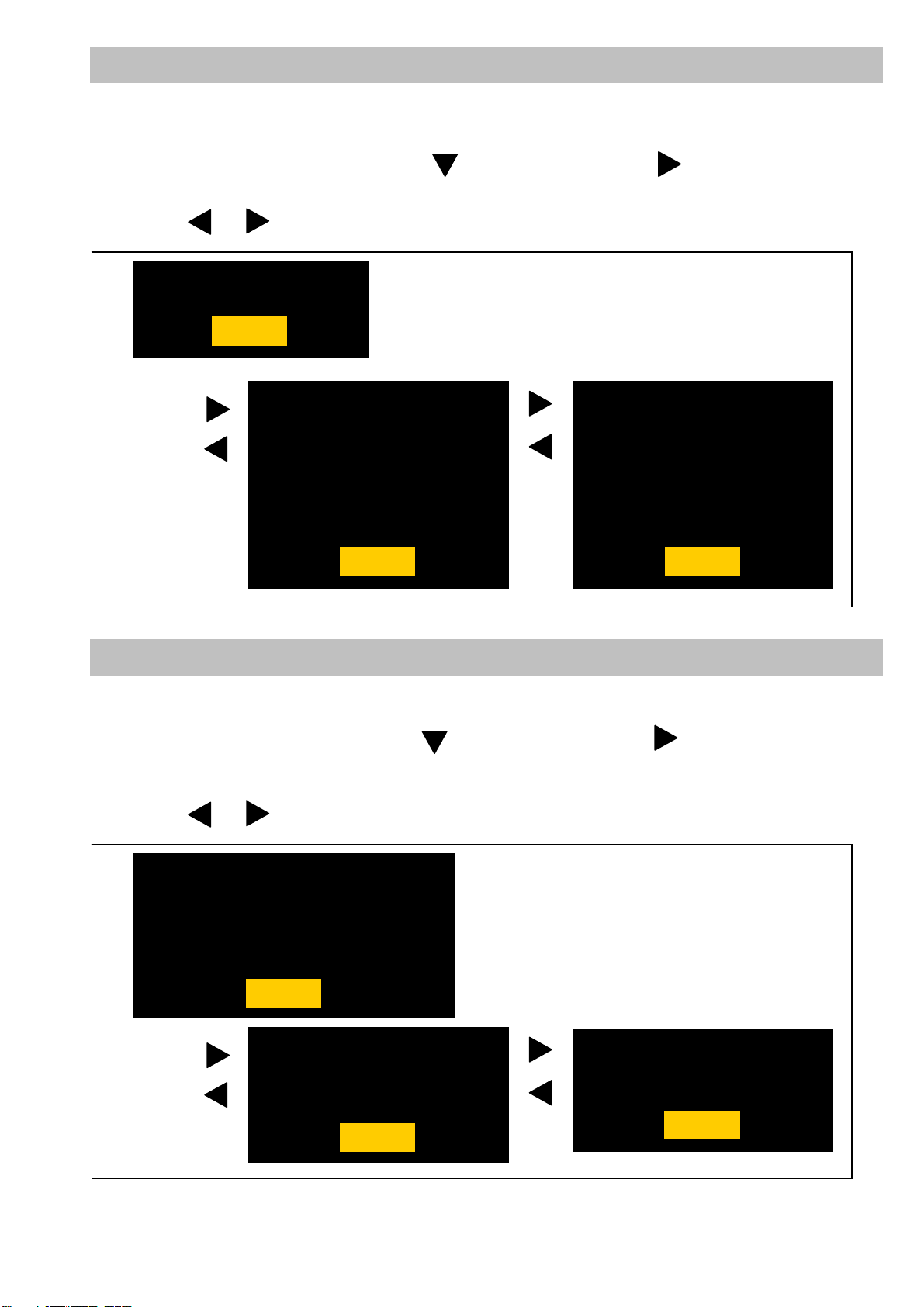
6-2. Version display method (SERVICE MENU)
Each software version can be confirmed at item “P2CS SERVICE” -> “VERSION” in SERVICE MENU.
1. Open SERVICE MENU by pressing <SHIFT> -> <STOP> -> <Control stick RIGHT> -> <RESET> -> <MENU>
button in order.
2. Select “P2CS SERVICE” with Control stick and then press Control stick . The yellow cursor moves to
SUB menu..
3. Select “VERSION” with Control stick and pressing the SET button, the all firmware version are displayed.
4. Pressing or Control stick, each software version is displayed.
VERSION : 8.51-00-F.00
OK
P2CS BL1 : 1.00-00-0.00
P2CS BL 2-1 : 1.00-00-0.00
P2CS BL 2-2 : 1.00-00-0.00
P2CS KR : 1.00-00-0.00
P2CS AP : 1.00-00-0.00
VUP : 1.00-00-0.00
VUP FS : 1.00-00-0.00
OK
SYSCON : 1.00-00-0.00
SYS BOOT : 1.00-00-0.00
SYS FONT : 1.00-00-0.00
CODEC SOFT : 1.00-00-0.00
CODEC IPL : 1.00-00-0.00
AVIO FPGA : 1.00-00-0.00
CAM EEPROM : 1.00-00-0.00
OK
6-3. Version display method (MAIN MENU)
Each software version can be confirmed at item “VERSION” of “DIAGNOSTIC” in Main menu.
1. Press MENU button for 3 seconds or more to display the MAIN MENU.
2. Select “DIAGNOSTIC” with Control stick and then press Control stick . The yellow cursor moves to
SUB menu..
3. Select “VERSION” with Control stick and pressing the SET button, the firmware version and the registered
information is displayed.
4. Pressing or Control stick, each software version is displayed.
VERSION : 8.51-00-F.00
MODEL NAME : AJ-PX270
SERIAL NO : A4TDA0003
MAC ADDRESS : 8C:C1:21:EF:D6:1E
UID : 00804582 19282004
OK
P2CS KR : 1.00-00-0.00
P2CS AP : 1.00-00-0.00
VUP : 1.00-00-0.00
VUP FS : 1.00-00-0.00
OK
SYSCON : 1.00-00-0.00
CODEC SOFT : 1.00-00-0.00
AVIO FPGA : 1.00-00-0.00
OK
INF-11
Page 14

6-4. Update with the SD memory card
CAUTION: Before Updating Software
● Do not power down or pull card while upgrading. If the program quits during loading, the dat a will be erased or
part writing condition and the restart is not made. However software can not be updated, please contact
Panasonic Service Engineering.
6-4-1. Preparation of update
< Preparation for SD memory card >
1. One piece of SD memory cards (SD: 64MB to 2GB, SDHC: 4GB to 32GB memory card) is required. Use only
SD memory cards that comply with the SD or SDHC specifications.
2. Insert an SD memory card into the card slot of this unit and format it.
NOTE: SD memory card used in this unit requires to be conformed to SD
memory card on this unit.
< Copy of Image data for update >
1. Download Image Data “VSI*****.zip” for the update from “Support Desk” web site.
2. Copy the file “VSI*****.zip” to hard disk of your PC and extract the file.
3. Insert a formatted SD memory card into the card slot of PC.
4. Copy the folder “PRIVATE” to one piece of SD memory cards. The downloaded image data (upgrade file:
VSI*****.img) is included in folder “PRIVATE”.
NOTE: Do not change the construction of folder and file name. The folder construction shown in the following and
top of directory should be “PRIVATE”.
Folder: PRIVATE MEIGROUP PAVCN SBG P2SD FW
File Name: VSI*****.img
< External Power >
It is best to power the unit from the external power supply. This will prevent the unit from shutting off during updating.
TM
standards. Be sure to format SD
INF-12
Page 15
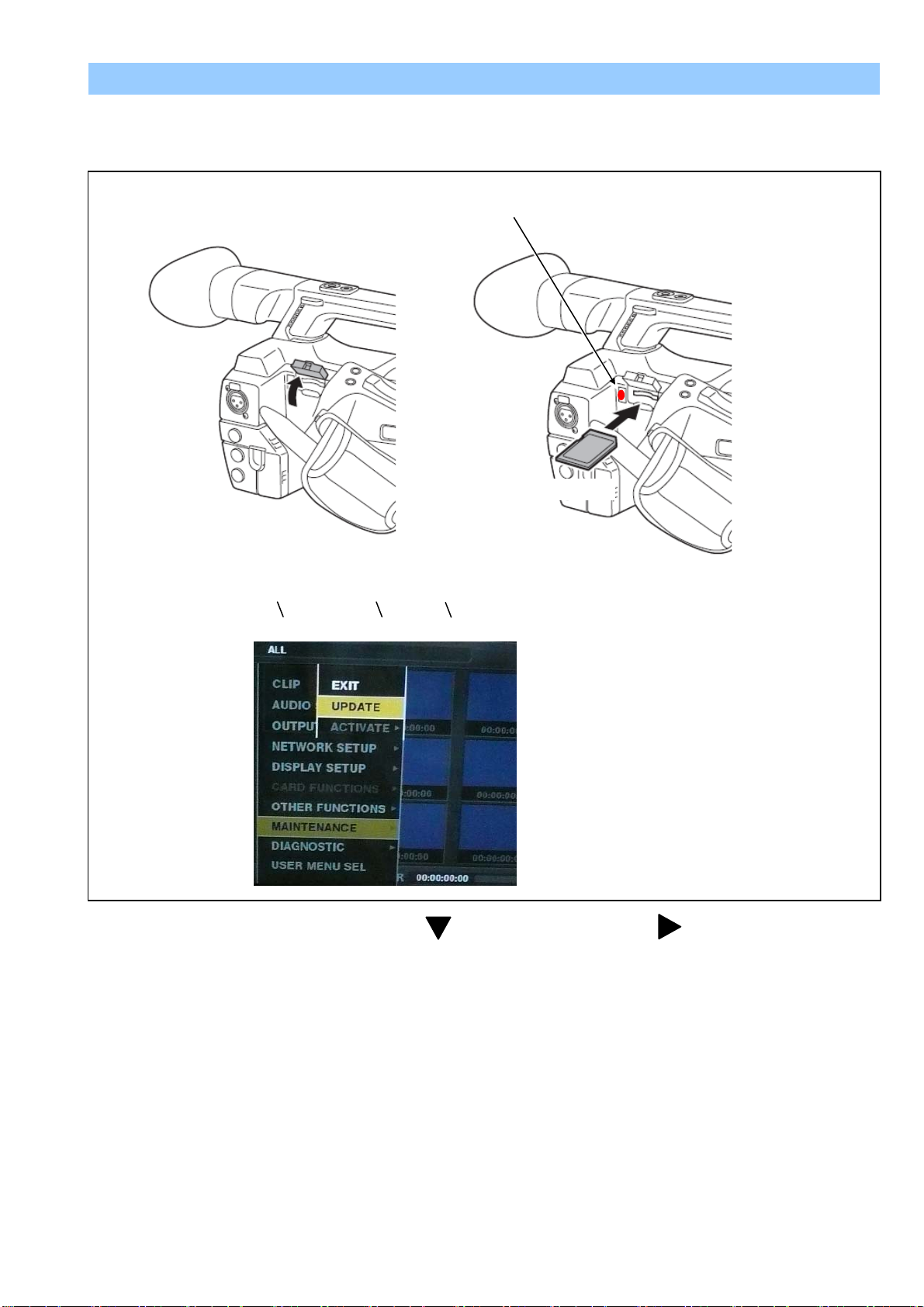
6-4-2. Updated procedure
1. Turn the power on. Press the THUMBNAIL button to thumbnail display screen mode.
2. Insert the SD memory card for update into the SD card slot of this unit.
3. Press the MENU button for 3 seconds or more to display the Main menu on thumbnail screen.
Busy lamp
SD memory card
THUMNAIL -> MAIN MENU -> MAINTENANCE -> UPDATE
4. Select “MAINTENANCE” with Control stick and then press Control stick . The yellow cursor moves to
SUB menu..
5. Select “UPDATE” with Control stick and pressing the SET button. (If the update SD memory card does not
insert into the unit, item “UPDATE” does not appeared.). The confirmation menu of the execution is displayed.
If update is executed, select the item “YES” and press SET button. In this time, BUSY lamp (SD Access LED)
is turned off.
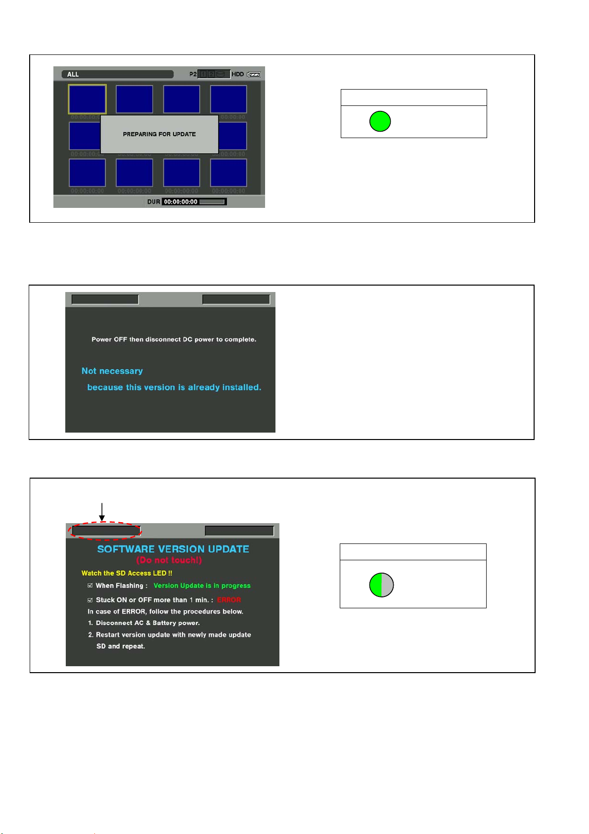
6. Update program is started and the message “PREPARING FOR UPDATE” appears on screen. In this timing, it
is doing preparation such as the confirmation of the data of the updating. In this time, BUSY lamp (SD Access
LED) is turned on.
INF-13
Page 16
NOTE: To shift to the screen in step 7, it might be necessary for about 60 seconds (Shift time changes with
capacity of an image file.).
SD Access LED
ON
NOTE: The following screen is displayed when there is data of the SD memory card in the same version.
Please remove the SD memory card and turn the power to OFF (In case of lower version, writing is
possible.).
7. When shifting to the update process of the flash and microcomputer, following screen is displayed. During
updating software, BUSY lamp (SD Access LED) is blink.
The name of firmware in the update is displayed.
SD Access LED
BLINK
In case that all firmware is updated, it takes approx. 45min (Time changes with capacity of an image file.).
INF-14
Page 17

8. In updating succeed, following screen is displayed. In this time, BUSY lamp (SD Access LED) is turned off.
SD Access LED
OFF
NOTE: If the update is not successful, an error message will appear as follows.
If the power supply is shut down on the way to update or above error operation happens, turn the powe r OFF/ON
then restart the write function start again in a few minutes.
9. Remove the SD memory card and turn the power supply of AC Adaptor OFF. Then power OFF the camera
recorder and power ON the power supply and camera recorder.
NOTE: ● Power OFF/ON by the power SW of camera recorder does not work just after updating the software.
Please shut OFF the external power supply.
● The power OFF and ON of camera recorder is required for updating data renewal.
10. Confirm that the number of software version is renewed for your confirmation update was correctly done.
INF-15
Page 18

NAME
Part Number
Pcs.
Remark
PC EVR software
VVS0114
1
Download from the Global Service WEB site.
USB Driver for AG-HPX250/260 EVR Adjustment
VSI5386B
1
Download from the Global Service WEB site.
USB cable A type ↔ mini B type
--- 1
Personal Computer
---
1
*NOTE:
7. PC EVR software
USB cable
mini B type
A type
STOP
RESET
EXIT
7-1. Required tools and equipment for PC EVR s oftware
When the PC EVR software is used, the following tools are required.
*OS: Windows XP SP2 / SP3, Windows7 32bit
7-2. Setup
7-2-1. Installation method of USB driver
VSI5386B has two U SB dr i ver for Windows XP and Windows7 32bit.
1. Download the file “USB Driv er f o r AG-HPX250/260 EVR Adjustment (VSI5386B)” from Global Service WEB
Site and extract it.
2. Set this camera recorder to COM mode.
< Setting method of COM mode >
2-1. Turn the power on.
2-2. The COM mode is set by hold down the “STOP” button, “EXIT” button and “RESET” button at the s ame
time for three seconds or more. (The character of “COM*” is displayed on the L CD screen when the COM
mode is set.).
NOTE: To cancel the COM mode, execute the o peration of the same button as the s etting. If the “ * “ mar k has
disappeared, COM mode is cancelled. When the power is turned ON next time, COM character disappears.
3. Connect the USB cable between USB connector and PC.
INF-16
Page 19

The following installation screen is for Windows Xp.
1. When the USB cable is connected between USB connector and PC, the following “Found New Hardware
Wizard” automatically opens on PC. In the window, check “Install from a list of specific location
(Advanced)” and click “Next” button.
2. The following sc reen is displa yed. Put the check in “Include this location in the sear ch” and click “Browse”
button.
3. The “Browse For Folder” screen is displayed. Select the f older that the driver entered. N ext, click “Next”
button on “Found New Hardware Wizard” screen.
INF-17
Page 20

4. The following message window may appear after a while clicking “Next” button on the “Found New Hardware
Wizard” screen. Click “Continue Anyway” button.
5. When the installation is completed, the following screen is displayed. Click “Finish” button.
INF-18
Page 21

7-3. Setup of PC EVR software
Select COM port number of your PC.
Communication starting button
1. Download the file “PC EVR Software (VVS0114)” from Global Service Web Site.
2. Make any directory and then copy all files in VVS0114.
3. Double click the “vvs0114.exe” in the “vvs0114” folder to boot-up the software. The following screen is
displayed.
4. After selecting COM port, click the “Connect” button to start communication between Camera and VVS0114.
INF-19
Page 22

7-4. Function of PC EVR software
< 1. Serial No. / Destination / MAC Address Read >
Clicking “Read” button for Serial No., Serial No. is displayed.
Clicking “Read” button for Model Name, Model Name is displayed.
Clicking “Read” button for MAC Address, MAC Address is displayed.
< 2. Destination setting >
After replacing the Main P.C.B, execute the Destination setting.
AJ-PX270(Japan), P, EN, AN, PX : Click “G set” button.
AJ-PX270EJ : Click “EJ set” button.
AJ-PX298MC : Click “298MC set” button.
AJ-PX285MC : Click “285MC set” button.
< 3. Version read >
Clicking “Read” button for Version, the total number of the firmware version is displayed.
< 4. Time / Zone setting >
The time and time zone of the internal clock is set.
AJ-PX270P,EJ,EN,AN,PX/PX298MC/285MC : Click “G / EJ / MC” button.
AJ-PX270(Japan) : Click “T(Japan)” button.
< 5. Hour Meter information >
Clicking “Read” button for Hour Meter, the hour meter information is displayed in Receive Data window.
NOTE: FAN hour meter is the effective information after Ver2 firmware.
INF-20
Page 23

OPERATION : Total operation hour
Read
Write
Input a number.
FAN1 : FAN operation hour
LCD : LCD operation hour
EVF : EVF operation hour
SERVO-ZOOM : ZOOM motor moving times
GRIP-ZOOM : GRIP ZOOM button operation times
HANDL-ZOOM : HANDLE ZOOM button operation times
P.ON-TIMES : The number of times of turning on power
< 6. Hour Meter Reset >
Clicking “Fan Reset” button, the hour meter of FAN is set zero hour.
When replacing FAN, click “Fan Reset” button for FAN Hour Meter.
NOTE: FAN hour meter reset is the effective function after Ver2 software.
Clicking “LCD Reset” button, the hour meter of LCD is set zero hour.
When replacing LCD, click “LCD Reset” button for LCD Hour Meter.
Clicking “EVF Reset” button, the hour meter of EVF is set zero hour.
When replacing EVF, click “EVF Reset” button for EVF Hour Meter.
Clicking “ZOOM Reset” button, the hour meter of SERVO-ZOOM motor is set zero hour.
When replacing ZOOM motor , click “ZOOM Reset” button for SERVO-ZOOM Hour Meter.
< 7. UID reading and writing >
Clicking “Read” button for UID, UID number is displayed.
When writing UID, input a number (8 figures) in the window and then click “Write” button.
If the number which should be written is not known, click “Write” button with a blank.
A number is generated and written in automatically.
When “&set UID OK” is displayed in Receive Data window, the writing is completed.
If unknown, with a blank.
INF-21
Page 24

< 8. CAM EEPROM READ >
Click “Read” button of CAM EEPROM. When Dump Data is displayed in RX Data window, Data Backup is
completed. It takes approx. 15 seconds.
Backup Data is saved as “PX270_yy_mm_dd_hh_nn.txt” file in “SaveRom” folder of vvs0114.
yy: year, mm: month, dd: day, hh: hour, nn: minute
< 9. CAM EEPROM WRITE >
1. Click “Write” button of CAM EEPROM. File selection dialog opens.
2. Select a backup file which you want to write from SaveRom folder.
3.Clicking “Open” button, the writing star t s. When “EEPROM W RITE FINISHED !” is displayed in Receive
Data window, t he writing is completed.
It takes approx. 9 minutes by the completion.
INF-22
Page 25

< 10. BE DATA READ >
Click “Read” button of BE. When “Data Backup completed!” message is displayed, Data Backup is completed. It
takes approx. 15 seconds.
NOTE: Backup Data is saved as “PX270_backup_yy_mm_dd_hh_nn.TXT” file in “SysBackup” folder of
vvs0114.
yy: year, mm: month, dd: day, hh: hour, nn: minute
< 11. BE D ATA WRITE >
1. Click “Write” button of BE. File selection dialog opens.
2. Select a backup file which you want to write from SysBackup folder.
3.Clicking “Open” button, the writing starts. When “WRITE Backup Data Completed!” message is
displayed, the writing is completed.
It takes approx. 10 seconds by the completion.
< 10. AWB / ABB >
Clicking “AWB” button, AWB is executed.
Clicking “ABB” button, ABB is executed.
When “&set CAM_ABB OK” or “&set CAM_AWB OK” is displayed in Receive Data window,
ABB (AWB) is completed.
INF-23
Page 26

< 11. CAM Adj. Mode setting >
It is a button which makes Camera adjustment mode.
In case of setting to adjustment mode, click “ON” button.
In case of releasing from adjustment mode, click “OFF” button.
When “&set CAM_FORCE_MODE OK” is displayed in Receive Data window, the setting is completed.
< 12. Shooting Mode setting >
Shooting mode can be changed with this button.
High Sens : Camera setting is set to High sensitivity mode.
Normal : Camera setting is set to Normal sensitivity mode.
Setting Off : The compulsive setting from PC is released.
When “&set CAM_SHOOTING_MODE OK” is displayed in Receive Data window, the setting is completed.
< 13. IRIS setting >
It is possible to set IRIS to the iris value indica ted on e ac h button.
Release : The compuls ive s etting from PC is released.
When “&set CAM_IRIS OK” is displayed in Receive Data window, the setting is completed.
INF-24
Page 27

< 14. Shutter setting >
It is possible to set Shutter to the shutter value indicated on each button.
Release : The compuls ive s etting from PC is released.
When “&set CAM_SHUTTER OK” is displayed in Receive Data window, the setting is completed.
< 15. ND filter se tting >
It is possible to set ND filter to the ND filter position indicated on each button.
When “&set CAM_FORCE_ND OK” is displayed in Receive Data window, the setting is completed.
< 16. GAMMA OFF setting >
It is possible to set GAMMA to OFF.
OFF : GAMMA is set to OFF.
Release : The compuls ive s etting from PC is released.
When “&set CAM_GAMMA_OFF OK” is displayed in Receive Data window, the setting is completed.
INF-25
Page 28

< 17. KNEE OFF setting >
It is possible to set KNEE to OFF.
OFF : KNEE is set to OFF.
Release : The compulsiv e s etting from PC is released.
When “&set CAM_KNEE_OFF OK” is displayed in Receive Data window, the setting is completed.
< 18. PEDESTAL OFF setting >
It is possible to set PEDESTAL to OFF.
OFF : PEDESTAL is set to OFF.
Release : The compulsive s etting from PC is released.
When “&set CAM_PEDESTAL_OFF OK” is displayed in Receive Data window, the setting is completed.
< 19. White Shading OFF setting >
It is possible to set White Shading to OFF.
OFF : White Shading is set to OFF.
Release : The compuls ive s etting from PC is released.
When “&set CAM_EVRRAM OK” is displayed in Receive Data window, the setting is completed.
< 20. AF Frame ON/OFF setting >
When adjusting Zoom Tracking, It is a button for displaying the focus window on the LCD panel.
ON : Focus window display ON
OFF : Focus window display OFF
When “&set CAM_DISP_AF_FRAME OK” is displayed in Receive Data window, the setting is completed.
INF-26
Page 29

< 21. Zoom position Wide setting >
It is possible to set Zoom position to Wide terminal.
When “&set LENS_ZOOM OK” is displayed in Receive Data window, the setting is completed.
< 22. Lens Adjustment St art >
In case of replacing Lens Unit or Main P.C. B, be sure to click th is “Start” button before starting L ens Adjustm ent.
By clicking this button, the initial setting data is set to EEPROM.
When “&set LENS_EEPROM OK” is displayed at the last line in Receive Data window, the initial setting is
completed.
< 23. IRIS OIS GYRO Adjustment >
When executing IRIS/OIS and GYRO adjustment, use these buttons.
IRIS OIS : for executing IRIS/OIS adjustment (Auto adjustment).
GYRO : for executing GYRO adjustment (Auto adjustment)
When “All Adjust Finish” is displayed in Receive Data window, the adjustment is completed.
If “NG” is displayed, Re-adjust again.
INF-27
Page 30

Adjustment button
< 24. ZOOM Lever Adjustment >
When executing ZOOM lever adjustment, use this button. This button is clicked 6 times while adjusting.
When “Get All Data. Adjust Data Backup to E2P” is displ ayed in Receive Data window at the last click ing, the
adjustment is completed.
If “Out of Range! Please Get ****** Again” is displayed, Re-adjust again.
< 25. IRIS Diameter Adjustment >
When executing IRIS Diameter adjustment, use these 6 buttons and 1 adjustment button.
Be sure to click “Start” button bef ore s tart in g t he adj u s tm ent. B y cl ic k ing th is b utt on, the initial setting dat a is s et to
EEPROM.
Be sure to click this “End” button after completing the adjustment.
“Step1” is a button for the coarse adjustment of IRIS Diameter F5.6.
“Step2” is a button for the coarse adjustment of IRIS Diameter F11.
“Set” is a button for sa ving the adjustment v alue of IRIS Diam eter, and also “Set” button is clic ked 3 tim es while
adjusting.
When “&set LENS_IRISOIS OK” is displayed in Receive Data window 3 times, the adjustment is completed.
When “&set LENS_IRISOIS NG” is displayed in Receive Data window, re-adjust again.
The “Adjustment” button operates only in the direction which closes IRIS.
INF-28
Page 31

Adjust Mode setting
Adjustment button
Save adjustment value
Adjust Start & End
setting
< 26. De-Focus/T racking Adjust >
When adjusting De-Focus and Zoom Tracking, use this button. Collimator and adaptor are necessary.
Execute : Adjustment automatically starts.
When “&set CAM_LENS_TRACKING OK” is displayed at last line in Receive Data window, the adjusting is
completed. Adjusting time takes about 1 minute.
When “&set CAM_LENS_TRACKING NG” is displayed in Receive Data window, re-adjust again.
< 27. Sensitivity Adjust >
When adjusting Sensitivity, use these buttons.
Be sure to click “Start” button bef ore s tart in g t he adj u s tm ent. B y cl ic k ing th is b utt on, the initial setting dat a is s et to
EEPROM.
Be sure to click this “End” button after completing the adjustment.
Adjust Mode : for setting to Sensitivity adjustment mode.
When “&set CAM_STD_SENSITIVE OK” is displayed in Receive Data window, the setting is completed.
Scroll button : for adjusting Sensitivity. Clicking button, G-ch level of White can be changed.
When “&set CAM_STD_SENSITIVE OK” is displayed in Receive Data window, the setting is successful .
Sens Save : for saving the Sensitivity adjustment value.
When “&set CAM_STD_SENSITIVE OK” is displayed in Receive Data window, the saving is completed.
INF-29
Page 32

3100K Adjustment
Mode setting
Execute A Gain
adjustment
Execute D Gain
adjustment
Total check
mode setting
Release
adjustment mode
5600K Adjustment
Mode setting
Execute 5600K
adjustment
Total check
mode setting
Release
adjustment mode
< 28. White Balance Adjust >
When adjusting White Balance, use these buttons.
Adjust Mode : for setting to White balance adjustment mode.
When “&set CAM_WHITE_BALANCE OK” is displayed in Receive Data window, the setting is completed.
A GAIN EXE : for adjusting Analog Gain of White balance (3100K). (Auto adjustment)
When “&set CAM_WHITE_BALANCE OK” is displayed in Receive Data window, the adjusting is completed.
D GAIN EXE : for adjusting Digital Gain of White balance (3100K). (Auto adjustment)
When “&set CAM_WHITE_BALANCE OK” is displayed in Receive Data window, the adjusting is completed.
5600K Adj : for adjusting 5600K White balance. (Auto adjustment) CC filter is necessary.
When “&set CAM_WHITE_BALANCE OK” is displayed in Receive Data window, the adjusting is completed.
Check Mode : Clicking this button, the monitor checking mode of white balance is set. (AWB setting = PRE 3.2K)
Adj End : Clicking this button, the White Balance adjustment mode is released.
< 29. Black Blemish compensation >
Blemish compensation is auto adjustment.
Execute : Clicking this button, the compensation starts. It takes approx. 5??? seconds by the completion.
END : After the adjustment, click this button. Adjustment mode is released.
When “&set CAM_DEFECT OK” is displayed in Receive Data window, the compensation is completed.
INF-30
Page 33

< 30. White Shading adjustment >
Execute White Shading
Position1, 2 setting
Adjustment
Shutter value setting
Shutter value display
Adjustment
When adjusting White Shading, use these buttons.
It is necessary to set the shutter value in two positions before executing this adjustment.
Position1 : for s etting shutter value at Posit ion1. After clicking this button, w hen clicking shutter button, shutter
value is displayed in the right window.
Position2 : for s etting shutter value at Position 2. After clicking this button, when c licking shutter button, shutter
value is displayed in the right window.
Setting : for setting two shutter value
WS Adjust : for White Shading adjustment. Clicking this button, White Shading adjustment automatically starts.
When “&set CAM_SHADING OK” is displayed in Receive Data window, the adjustment is completed. It takes
approx. 10 seconds by completion.
adjustment
< 31. ND Filter adjustment >
When executing ND Filter adjustment, use these buttons.
Step1 : for setting ND filter adjustment mode. After settings completed, Message box opens.
Step2 : Clicking this button, the adjustment of ND2, ND3, and ND4 is automatically executed.
When the adjustment is OK, “Completed” message opens.
When the adjustment is NG, “Re-Try” message opens.
END : The adjustment mode is released.
OK
NG
INF-31
Page 34

Input a ch eck m ark in the
Adjustment value display
Adjustment button
Adjustment button
Adjustment value display
Adjustment value display
Adjustment button
After adjustment, click Set
< 32. LEVEL Adjustment >
When adjusting each Video level, use these buttons.
Read : Clicking this button, the adjustment value is displayed.
Scroll button : for adjusting each level. Clicking button, each video level can be changed.
When “&set Y_LEVEL_60Hz OK” or “&set C_LEVEL_60Hz OK” or “&set Y_LEVEL_50Hz OK”… is displa yed
in Receive Data window, the setting is successful .
Check button : Input a check mark in the adjustment item.
adjustment item
< 33. INT Clock Frequency Adjustment >
When adjusting INT 27MHz Clock frequency, use these buttons.
Read : Clicking this button, the adjustment value is displayed.
Scroll button : for adjusting INT 27MHz frequency. Clicking button, the frequency can be changed.
When “&set 27M_VCXO OK” is displayed in Receive Data window, the setting is successful .
< 34. LCD Back Light Adjustment >
When adjusting LCD back light, use these buttons.
Scroll button : for adjusting LCD back light. Clicking button, the brightness of the back light can be
changed.
When “&set LCD_BL_0 OK” is displayed in Receive Data window, the setting is successful .
Set : After the adjustment, click this button so that the adjustment value is registered.
INF-32
Page 35

OK
OK
Temperature
< 35. MIC Balance Adjust >
When adjusting internal MIC Balance, use this button.
Execute : Adjustment automatically starts.
When “&set INT_MIC_LEVEL OK” is displayed in Receive Data window, the adjusting is completed.
When “&set INT_MIC_LEVEL NG” is displayed in Receive Data window, re-adjust again.
< 36. LEVEL Gauge Adjust >
When adjusting Level Gauge Balance, use this button.
Execute : Adjustment automatically starts.
When “&set LEVEL_GAUGE OK” is displayed in Receive Data window, the adjusting is completed.
When “&set LEVEL_GAUGE NG” is displayed in Receive Data window, re-adjust again.
< 37. MOS Temperature >
It is possible to confirm MOS temperature.
When clicking this button, MOS temperature is displayed in Receive Data window.
In the following example, MOS temperature is 56 degree.
INF-33
Page 36

< 38. Other >
COM Port and communication setting can be set in the communication un-connection.
Port setting
It is possible to change from COM1 to COM6 in the port setting. Please set to the COM port number of PC.
Clicking “SETTING” button, the following screen is displayed and following items can be set.
● Baud Rate, ● Party, ● Data Length, ● Stop Bit
The setting need not be changed.
Communication
setting button
INF-34
Page 37

8. Data Backup Procedure
In this Camera Recorder, it is possible to backup 3 kinds of the adjustment or setting data.
1. Camera adjustment data which is stored in EEPROM of SYSCON micon. (IP1500)
2. The unique data and BE side adjustment data which is stored in memory of SYSCON micon. (IP1500)
3. Scene File and User File which is saved in Flash memory of PQ micon (IP3900, IP3903)
The adjustment and setting data of Item No.1, and 2 can be backed-up by using PC EVR Software “VVS0114”.
The saving data in PQ micon (item No.3) can be backed-up to SD card with Main Menu operation (MAIN MENU ->
CARD FUNCTIONS). Please refer to Operating Instructions.
For the data backup, the following tools are required.
< Required tools and equipment >
NAME
PC EVR Software VVS0114 1 Download from Service WEB site
Personal Computer --- 1
USB Driver for AG-HPX250/260 EVR Adjustment
USBC cable A type ↔ mini B type --- 1
SD card --- 1
NOTE: USB driver is required. Please refer to item “7-2-1. Installation method of USB driver”.
Part
Number
VSI5386B 1
Pcs. Remark
*OS: Windows XP SP2 / SP3
Windo ws7 32bit
Download from the Global Service WEB site.
For Scene file and User file backup
8-1. Setup
1. Set this camera recorder to COM mode.
< Setting method of COM mode >
1-1. Turn the power on.
1-2. The COM mode is set by hold down the “STOP” button, “EXIT” button and “RESET” button at the same
time for three seconds or more. (The character of “COM*” is displayed on the LCD screen when the COM
mode is set.).
NOTE: To cancel the COM mode, execute the operation of the same button as the setting. If the “ * “ mark has
disappeared, COM mode is cancelled. When the power is turned ON next time, COM character disappears.
2. Connect the USB cable between USB connector and PC.
STOP
RESET
EXIT
mini B type
INF-35
USB cable
A type
Page 38

8-2. Back Up Procedure
8-2-1. CAM EEPROM DUMP
1. Turn on the Camera Recorder and the Personal Computer.
2. Set the Camera Recorder to COM mode.
3. Double click the “VVS0114.exe” in the “vvs0114” folder to boot-up the software.
4. After selecting COM port, click the “Connect” button to start communication between Camera and VVS0114.
5. Click “Read” button of CAM EEPROM . When Dump Data is displayed in RX Data window, Data Backup is
completed. It takes approx. 15 seconds.
NOTE: Backup Data is saved as “PX270_yy_mm_dd_hh_nn.TXT” file in “SaveRom” folder of vvs0114.
yy: year, mm: month, dd: day, hh: hour, nn: minute
Select COM port number of your PC.
Communication starting button
INF-36
Page 39

8-2-2. BE Data Backup
1. Turn on the Camera Recorder and the Personal Computer.
2. Set the Camera Recorder to COM mode.
3. Double click the “VVS0114.exe” in the “vvs0114” folder to boot-up the software.
4. After selecting COM port, click the “Connect” button to start communication between Camera and VVS0114.
5. Click “Read” button of BE . When “Data Ba ckup complete d!” message is displayed, Data Backup is
completed. It takes approx. 15 seconds.
NOTE: Backup Data is saved as “PX270_backup_yy_mm_dd_hh_nn.TXT” file in “SysBackup” folder of
vvs0114.
yy: year, mm: month, dd: day, hh: hour, nn: minute
8-3. Backup Data Writing Procedure
8-3-1. CAM EEPROM Writing Procedure
1. Click “Write” button of CAM EEPROM. File selection dialog opens.
2. Select a backup file which you want to write from SaveRom folder.
3.Clicking “Open” button, the writing starts. When “EEPROM WRITE FINISHED!” is displayed in Receive
Data window, the writing is completed.
It takes approx. 9 minutes by the completion.
INF-37
Page 40

8-3-2. BE Data Writing Procedure
1. Click “Write” button of BE. File selection dialog opens.
2. Select a backup file which you want to write from SysBackup folder.
3.Clicking “Open” button, the writing starts. When “WRITE Backup Dat a Completed! ” message is
displayed, the writing is completed.
It takes approx. 10 seconds by the completion.
INF-38
Page 41

9. White Blemish Compensation
< Features >
a ) It is possible to compensate blemish of each color signal individually (R, G, B and Y).
(Total amount: 256 points)
b ) It is possible to compensate blemish without extra equipment (PC, Service fixtures etc.).
c ) Automatic blemish compensation function. Also it is possible to compen sate manually.
9-1. Blemish Compensation flow
This machine has Automatic blemish compensation function.
Blemish compensation is executed automatically when ABB is executed in the normal operation.
(Start ABB functions first and goes on to compensate the blemish.)
Fine adjustment by cursor manually.
(Only when automatic compensation does
not provide complete compensation)
Automatic compensation is executed with ABB (ABB is executed three times.)
Confirm results (on TV monitor) (Follow the item 9-3-1)
NG
(Follow the item 9-3-2)
OK
Check the Blemish on the monitor
Finish
OK
9-2. Connection
Connect the HD SDI OUT terminal of the camera and the TV-monitor (Confirms with HD SDI).
TV-monitor
HD SDI OUT
INF-39
Page 42

9-3. Blemish Compensation Procedures
1. About 2-hours aging or operation is required before starting an adjustment.
2. Set each SW as shown below.
GAIN : L (0dB)
WHITE BAL SW : PRST <3200K>
SHUTTER : OFF
3. Set the Camera shooting mode as shown below.
SHOOTING MODE: HIGH SENS ( MENU -> SYSTEM MODE -> SHOOTING MODE )
9-3-1. Blemish confirmation
Please confirm whether all blemishes were compensated with this status display by viewing the TV-monitor. As the
standard of a confirmation, Blemish compensation specification is shown below.
Observation environment
Measurement part HD SDI OUT connector (Confirms with HD SDI)
Circumstance temperature
SYSTEM 59.94i or 50i (Either is OK)
SHOOTING MODE HIGH SENS
GAIN setting L (0dB)
SHUTTER OFF
AWB SW setting PRST (3200K PRESET)
MEDIAN FILTER ON or OFF (Either is OK)
Specification
Confirm that the blemish is in specification 1 (watch).
If it is out of specification, measure the level of blemish at waveform monitor (HD SDI OUT), and
Confirm that the level of blemish at each channel(R,G,B) is in the specification 2 (measurement).
< Specification 1 (watch) >
The white blemish does not appear on the monitor TV.
< Specification 2 (measurment) >
Contrast ratio *1 All Zone
R ch / G ch B ch
20% or more 40% or more 0
20% or less 40% or less No count *2
*1 Contrast ratio: Compared with white portion of the internal color bars signal is full (100%).
*2 No count: The number of blemish is not counted.
77F (25C) About 2-hours aging
INF-40
Page 43

9-3-2. Manual compensation procedure
In case all blemishes are not compensated in automatic compensation (ABB), it is also possible to perform blemish
compensation manually by using the cursor. Following shows then concrete manual compensation procedures for
various cases.
I ) Manual compensation for position which was not detected automatically
1. Close LENS iris and open the “<DEFECT (EDIT)>" page in SERVICE menu.
2. Select "MODE" item and set it from "EDIT" to "NEW".
(No need to decide "DEFECT NO.". DEFECT NO. is automatically set by CAMERA CPU.)
3. Set following item.
SIZE : 3
COLOR : *NOTE
EXIT
MODE
MODE NEW
DEFECT NO
H CURSOR COARSE
H CURSOR FINE
V CURSOR COARSE
V CURSOR FINE
SIZE
COLOR
DEFECT EDIT STATUS
ENTRY
DELETE
NEW
000
02
3E
01
38
3
R
OFF
ENTRY (NEW) page
4. Observe TV-monitor and then adjust item “H CURSOR COARSE” or “H CURSOR FINE” so that the H cursor
position moves to the target blemish.
5. Observe TV-monitor and then adjust item “V CURSOR COARSE” or “V CURSOR FINE” so that the V cursor
position moves to the target blemish. Then the blemish will disappear automatically.
6. When the blemish does not disappear by positional specification of cursor, the item of “COLOR" is used. Set
item "COLOR" as follows.
<COLOR>
This item specifies the color of MOS sensor with a blemish. When the setting value of this item is changed with
R, G, and B from Y and a blemish disappears, a color when a blemish disappears is set up.
NOTE: When the blemish does not disappear well by R, G or B is selected, Y is selected. When Y is selected,
R, G, and B colors are corrected.
7. Select “ENTRY” item, and push JOG Dial button. Then Select “YES” and push JOG dial button again.
8. When “ENTRY” character appears on the lower left of the screen, data store will be completed.
9. Close menu screen and then turn off the power of the Unit.
*NOTE: Select to R, G or B where blemish has
been generated.
Blemish
V CURSOR
COARSE/FINE
H CURSOR
COARSE/FINE
INF-41
Page 44

9-4. Remarks
9-4-1. Delete registered data one by one
1. Open “<DEFECT (EDIT)>” page in SERVICE menu.
2. Select “DEFECT NO.” to desired position of cursor.
3. Select “DELETE” item, and push “JOG dial” button.
4. Appear “DELETE?” “YES/NO” message, then select “YES” and push “JOG dial” button.
5. When “DELETE OK” appears on the lower left of the screen, One blemish data will be deleted.
6. Close menu screen and then turn off the power of the Unit.
9-4-2. Change Parameter about blemish compensation
1. Open “<DEFECT (EDIT)>” page in SERVICE menu.
2. Select “DEFECT NO.” to desired position of cursor.
3. Change some parameters in “<DEFECT (EDIT)>” page (COLOR, SIZE etc.).
4. Select “ENTRY” item, and push “JOG dial” button.
5. Appear “ENTRY?” “YES/NO” message, then select “YES” and push “JOG dial” button.
6. When “ENTRY” appears on the lower right of the screen, data change will be completed.
7. Close menu screen and then turn off the power of the Unit.
9-4-3. About the position inhibited to register the compensation data
When there is already registered blemish compensation data, depending on the position relation of the newly
registered blemish compensation position (cursor position), blemish compensation operation may not be performed
normally. In that case, cursor is flashed on the screen, and a blemish compensation position cannot be registe red.
When blemish compensation data is added with the registered blemish compensation data, the inhibit position for
blemish compensation is as follow.
Registered blemish
compensation size
1,2,3
5
7 7 ± 9
Ex.: When the 5 pixel compensation data is added to registered 7 pixel compensation data
The position shown in the gray of the following figure turns into a registration prohibition position.
: Registered blemish compensation position (There is compensation data of 5 pixel)
: Registration inhibited position (The compensation data of the 7 pixel cannot register additionally.)
Additional blemish
compensation size
1,2,3 ± 5
5 ± 6
7 ± 7
5 ± 7
7 ± 8
Horizontal direction Vertical direction
Range of inhibit position
± 1
INF-42
Page 45

10. Operation after major part exchanged
10-1. Operation List
X: Operation required
Replacement Parts Adj.
MAIN FRAME
LENS
HANDLE U
GRIP U
SIDE CASE R U
LCD U
EVF U EVF U Not required
BATTERY U BATTERY P.C.B X IRIS OIS GYRO
MAIN P.C.B. X X X
TOP P.C.B. Not required
BOTTOM P.C.B Not required
POWER P.C.B Not required
POWER SUB P.C.B Not required
P2CARD P.C.B X
U P2CARD P.C.B Not required
AUDIO OUT P.C.B
LENS U X
HANDLE OP P.C.B X
HANDLE ZOOM GPS
P.C.B
LCD OPEN SENS P.C.B Not required
INT MIC X MIC Balance
HANDLE ZOOM U Not required
USB P.C.B Not required
FRONT SS P.C.B Not required
POWER SW P.C.B Not required
ZOOM SW P.C.B X ZOOM Lever
CAM OP FPC Not required
FRONT AUD VR P.C.B Not required
AUDIO OP P.C.B Not required
SHUTR DIAL P.C.B Not required
TOGGLE SW P.C.B Not required
MONITOR P.C.B X LCD Back Light
Not required
Version
conf.
EEPROM
backup
Remark
Not required
Lithium battery
Time / Zone setting
LEVEL Gauge
MIC Balance
INF-43
Page 46

10-2. Operation flow chart after replacement of major parts
10-2-1. MAIN P.C.Board.
Is it possible to backup the data
of CAM EEPROM and BE DATA?
Please operate following < Procedure 2 >
NO
< PROCEDURE 1 >
Save the Scene File data into SD card.
Save the User file into SD card.
Backup the CAM EEPROM & BE Data.
Replace the MAIN P.C.Board.
Destination setting.
Refer to item <2. Destination setting> of item “7-4. Function of PC EVR software”.
Transfer the backuped CAM EEPROM & BE Data to new P.C.Board.
( It continues to next page. )
YES
Please operate following < Procedure 1 >
Refer to “Operating Instructions” about
saving the data into SD card.
Refer to item “8. Data Backup
Procedure” about backup procedure.
INF-44
Page 47

Confirm that the software version.
(Refer to item “6-2. Version display
method” about version display procedure.)
●SYSCON, ●P2CS, ●VUP, ●CODEC,
●AVIO FPGA
Be the latest version.
(Refer to Global Service WEB Site
about number of latest version.)
NO
YES
Refer to item “6-4. Update with the SD
memory card about update procedure.
Update to latest version.
Adjustment is required.
Refer to item “10-3. Adjustment after replacement of major parts”.
Load the backed up Scene File data to new board.
Refer to “Operating Instructions” about
loading the data to Camera.
Load the backed up User File to new board.
Overall Check
INF-45
Page 48

< PROCEDURE 2 >
Save the Scene File data into SD card.
Save the User File into SD card.
Destination setting.
Refer to item <2. Destination setting> of item “7-4. Function of PC EVR software”.
Write the Serial Number.
With Serial Number Writing procedure, please consult service department of
Professional A V .
Write UID.
Refer to item <7. UID reading and writng> of item “7-4. Function of PC EVR software”.
Confirm that the software version.
(Refer to item “6-2. Version display
method” about version display procedure.)
●SYSCON, ●P2CS, ●VUP, ●CODEC,
●AVIO FPGA
Be the latest version.
(Refer to Global Service WEB Site
about number of latest version.)
Replace the MAIN P.C.Board.
YES
( It continues to next page. )
Refer to “Operating Instructions” about
saving the data into SD card.
NO
Refer to item “6-4. Update with the SD
memory card about update procedure.
Update to latest version.
INF-46
Page 49

Adjustment is required.
Refer to item “10-3. Adjustment after replacement of major parts”.
Load the backed up Scene File data to new board.
Refer to “Operating Instructions” about
loading the data to Camera.
Load the backed up User File to new board.
10-2-2. LENS Unit
Replace the LENS Unit
Adjustment is required.
Refer to item “10-3. Adjustment after replacement of major parts”.
Overall Check
Overall Check
10-2-3. LCD Unit / MONITOR P.C.Board.
Replace the LCD Unit / MONITOR P.C.Board
LCD Back Light adjustment is required.
Refer to item “10-3. Adjustment after replacement of major parts”.
Overall Check
INF-47
Page 50

10-2-4. BATTERY Unit / BATTERY P.C.Board.
Replace the BATTERY Unit / BATTERY P.C.Board
IRIS OIS GYRO adjustment is required.
Refer to item “10-3. Adjustment after replacement of major parts”.
Overall Check
10-2-5. GRIP Unit / ZOOM SW P.C.Board.
Replace the GRIP Unit / ZOOM SW P.C.Board
ZOOM LEVER adjustment is required.
Refer to item “10-3. Adjustment after replacement of major parts”.
Overall Check
10-2-6. HANDLE Unit / HANDLE OP P.C.Board.
Replace the HANDLE Unit / HANDLE OP P.C.Board
LEVEL Gauge and MIC Balance adjustment is required.
Refer to item “10-3. Adjustment after replacement of major parts”.
Overall Check
INF-48
Page 51

10-2-7. INT MIC.
MIC Balance adjustment is required.
Refer to item “10-3. Adjustment after replacement of major parts”.
Replace the INT MIC
Overall Check
INF-49
Page 52

10-3. Adjustment after replacement of major parts
When the following parts is replaced showing in the table below, the adjustment and confirmation are required follow the
items shown by mark “X” in the table.
Please perform the content of operation shown in the item “10-2. Operation after major parts exchanged” of service
information (SECTION 1) when you each circuit board or unit is replaced.
INT
MIC
GRIP
Unit
Zoom
SW
PCB
PART NAME
NO ADJUSTMENT
2-2 IRIS OIS GYRO
2-3 ZOOM Lever
2-4 IRIS Diameter
2-5 Sensitivity
2-6 Zoom tracking/De-focus
2-7 White Balance (3100K)
2-8 White Balance (5600K)
2-9 White Shading
Black Blemish
2-10
Compensation
2-11 ND Filter
2-12 VBS LEVEL (59.94Hz)
2-13 VBS LEVEL (50Hz)
2-14 INT Clock Frequency
2-15 LCD Back Light
2-16 LEVEL Gauge
2-17 MIC Balance
2-18 Time / Zone setting
White Blemish
2-19
Confirmation
*MAIN P.C.B.
When
Backup
When no
backup
LENS
Unit
HANDLE Unit
Handle
OP PCB
X X X X
X X
X X X
X X X
X X X
X X
X X
X X
X X
X X
X X
X X
X X
X X
X X X X
X X X X X
X X
X X X
X: Adjustment / Confirmation Required
T he method of data backup (CAM EEPROM) has been described to the item “8. Data Backup Procedure” of service
information (SECTION 1).
The method of white blemish compensation has been described to the item “9. White Blemish Compensation” of service
information (SECTION 1).
LCD
Unit
Monitor
PCB
Battery
Unit
Battery
PCB
INF-50
Page 53

11. P.C.Board Location
INF-51
 Loading...