

Page 1

Panasonic Broadcast
AG-DV2500
Menu Information
Page 2
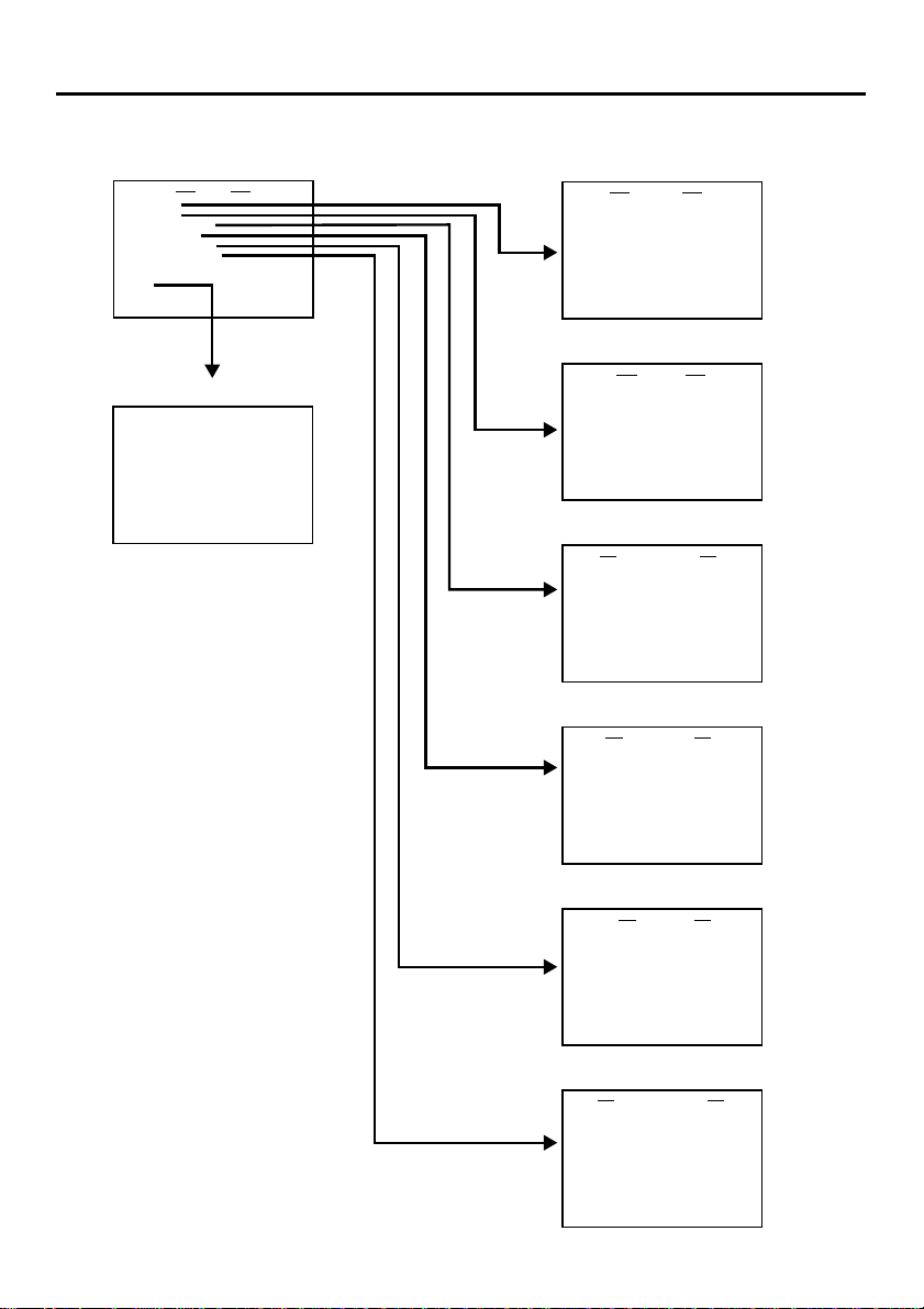
MENU SCREEN – Structure of the menu –
Hierarchical menus are displayed on the monitor.
Top MENU screen
SYSTEM. .
REMOTE . .
AUD I O /VIDEO..
TIME CODE . .
DISPLAY SET . .
CLOCK ADJUST. .
FACTORY SETTING CANCEL
DRUM HOUR MET ER 000000H
EX I T
MENU
Normal screen
32K CH–1 / 2 0
10/ 10 / 02 STANDBY-OFF
12: 00 : 00 TCR 02:00:00:00
min
SYSTEM menu screen
––– SYSTEM–––
ST I L L MODE F I ELD
SERI ES REC T I ME OFF
ST I L L T IMER 5MI N
PAUSE PROTECT F . ADV
W
RITE ON
INDEX
DC I N MODE PO
PAGE BACK
W
ER OF F
REMOTE menu screen
LOCAL FUNCTI ON STP+E JT
PREROLL 7SEC
RE
REM STOP SE L EE
PLAY DELAY OF
SYNCHRONI ZAT ION ON
CONTROLLER SEL T YPE3
PAGE BACK
REMOTE
M
FF /REWMOD E F F / RE
W
AUDIO/VIDEO menu screen
AUD I O / V I DEO
AUD I O MODE 48 K
A.OUT AT SEARCH OFF
AUD I O OUT SEL CH-1/2
AUD IO OUT LEVNORM
SET UP( NTSC ) OFF
PAGE BACK
TIME CODE menu screen
–––TIME CODE–––
TC 00 :0 0 : 00:00
CLEAR CANCEL
NDF /D F ( N TSC ) DROP
DV TC DUP . OFF
TC OUT OFFSE T OFF
PAGE BACK
DISPLAY menu
DISPLAY ON
COUNT ER POS I . LO
TIME CODE ON
VTR MODE ON
TAPE REMA IN OFF
TIME/DATE OFF
AUD I O I NFO . OF F
DATE STYL E M/D / Y
TIME STYLE 24HOUR
BARS OFF
PAGE BACK
DISPLAY
screen
W
ER - R
CLOCK ADJUST menu screen
–––CLOCK ADJUST–––
DATE ( M / D / Y )10/10/02
TIME 00:00
PAGE BACK
E-51
Page 3
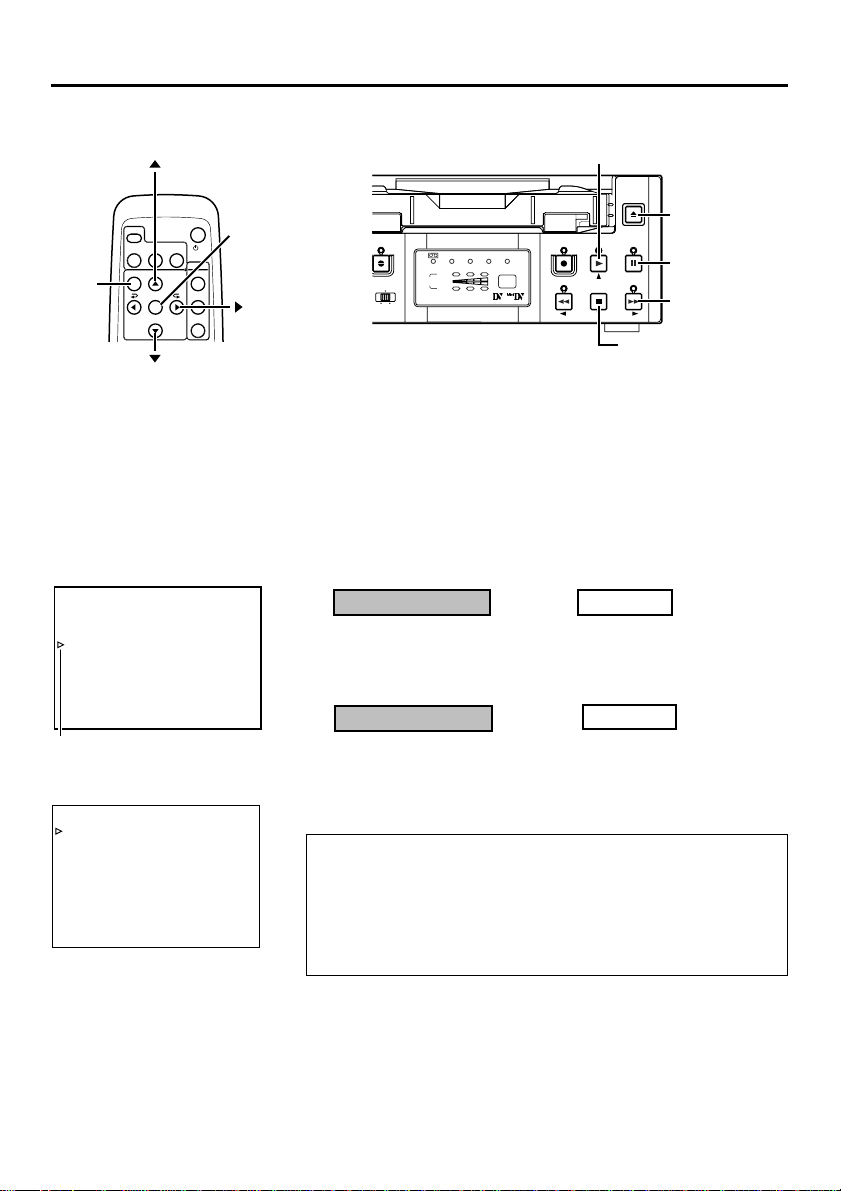
MENU SCREEN – Setting the menu –
The various functions of this unit can be set from the menu. The configured settings are
saved in the unit's memory and are maintained even after the power is turned off.
button
VCR
DISPLAY
STILL
BLANK
BARS
MODE
MENU
button
MENU SEARCH+
SET
SEARCH–
OUT SEL.
OUT LEV.
button
Top MENU
–––MENU–––
SYSTEM. .
REMOTE . .
AUD I O / V I DEO . .
TIME CODE . .
DISPLAY SET. .
CLOCK ADJUST . .
FACTORY SETTING CANCEL
DRUM HOURMETER 000000H
EX I T
Cursor
SYSTEM menu
–––SYSTEM–––
ST I L L MODE F I ELD
SER I ES REC T I ME OFF
ST I L L T I MER 5MIN
PAUSE PROTECT F . ADV
W
RITE ON
INDEX
DC I N MODE PO
PAGE BACK
POWER
AUDIO
MUTING
/I
W
SET button
ER OFF
button
A.DUB
INPUT
DV
CH
LINE
S-VIDEO
REC INH.
PAL
NTSC
DVCAM
1 / 3
2 / 4
AUDIO
The menu screen settings can be done while viewing the monitor connected to the VIDEO LINE OUT or S-VIDEO OUT terminal, using either the remote controller or the buttons on the main unit.
Set the unit to the STOP mode.
To perform setting with the operation buttons on the main unit, first
remove the cassette if one is loaded.
1.
Display the top MENU.
Remote controller
Press the MENU button.
2.
Display the menu for setting.
Remote controller
Press the / button and
1
bring the cursor to the item
to be set.
Press the SET or button.
2
• If the EXIT item of the top MENU is selected, the usual screen
resumes.
• If the FACTORY SETTING item of the top MENU is set to “EXECUTE”, the set values on the menu will be reset to those initially set at manufacture. (Except DRUM HOUR METER)
• The DRUM HOUR METER item cannot be set.
PLAY button
EJECT
EJECT button
MENU
PLAY
REC
REW
PAUSE
PAUSE button
SET
FF
STOP
FF button
STOP button
Main unit
Press the EJECT and STOP
buttons simultaneously while
no cassette is loaded.
Main unit
Press the PLAY/STOP but-
1
ton and bring the cursor to
the menu item.
Press the PAUSE or FF but-
2
ton.
E-52
Page 4
button
PLAY button
MENU button
button
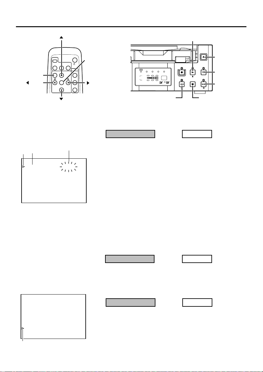
SYSTEM menu
Items
Cursor
–––SYSTEM–––
ST I L L MODE F I ELD
SER I ES REC T I ME OFF
ST I L L T I MER 5MIN
PAUSE PROTECT F . ADV
W
RITE ON
INDEX
DC I N MODE PO
PAGE BACK
DISPLAY
STILL
BARS
MODE
MENU SEARCH+
SEARCH–
VCR
SET
Settings
BLANK
button
W
ER OFF
POWER
AUDIO
MUTING
OUT SEL.
OUT LEV.
/I
SET button
button
3.
EJECT
EJECT button
MENU
PLAY
REC INH.
PAL
NTSC
DVCAM
1 / 3
CH
2 / 4
O
AUDIO
REC
REW
REW button
PAUSE
STOP
STOP button
SET
FF
PAUSE button
FF button
Set the items on the menu.
Remote controller
Press the / button and
1
bring the cursor to the item
to be set.
Press the SET or button.
2
¥
The selected value blinks and becomes available for changing.
Press the / button to
3
change the value as desired.
Press the SET button to
4
confirm the value.
¥ The value stops blinking and is confirmed.
Repeat steps 1 - 4 above and perform the necessary set-
5
tings.
Main unit
Press the PLAY/STOP but-
1
ton and bring the cursor to
the item to be set.
Press the PAUSE or FF but-
2
ton.
Press the PLAY/STOP but-
3
ton to change the value as
desired.
Press the PAUSE button to
4
confirm the value.
Top MENU
–––MENU–––
SYSTEM. .
REMOTE . .
AUD I O / V I DEO . .
TIME CODE. .
DISPLAY SET. .
CLOCK ADJUST . .
FACTORY SETTING CANCEL
DRUM HOUR ME TER 000000H
EX I T
Cursor
4.
To return to the previous screen, do either of the following:
Remote controller
• Press the
button.
Or
• Select PAGE BACK.
5.
To return to the usual screen, do either of the following:
Remote controller
• Press the MENU button.
Or
• Select EXIT from the top
MENU.
Main unit
• Press the REW button.
Or
• Select PAGE BACK.
Main unit
• Press the EJECT button.
Or
• Select EXIT from the top
MENU.
E-53
Page 5

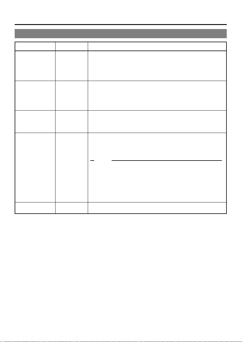
MENU SCREEN – Contents of the menus –
In the menu descriptions below, settings with marks are factory settings.
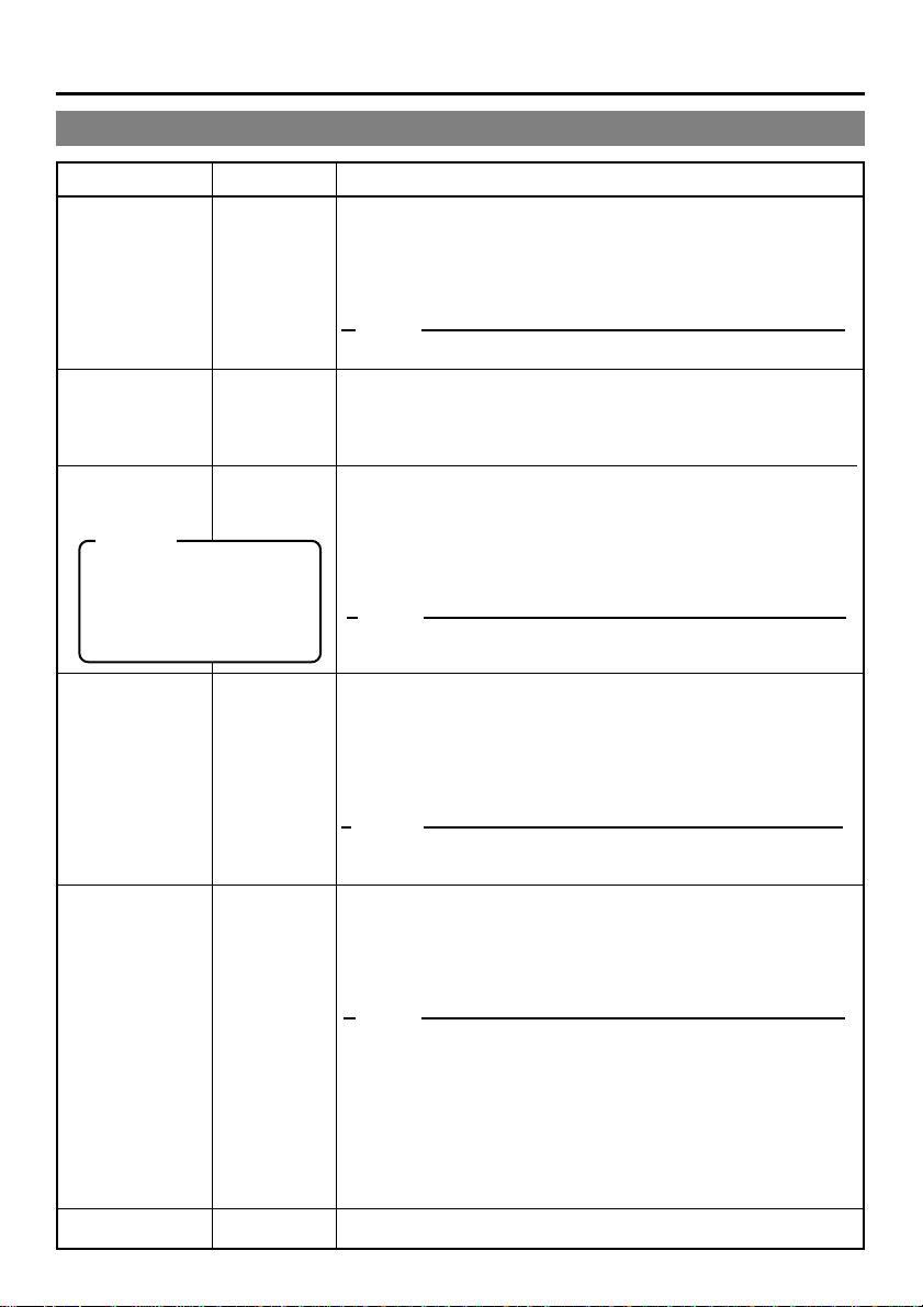
Top MENU
Items Setting Contents
SYSTEM
Displays the menus related to the operation system of this unit.
REMOTE
AUDIO/VIDEO
TIME CODE
DISPLAY SET
CLOCK ADJUST
FAC TORY
SETTING
DRUM HOUR
METER
EXIT
CANCEL
EXECUTE
Displays the menus related to the remote controller.
Displays the menus related to the audio and video.
Displays the menu for setting time codes.
Displays the menu related to the displays on the monitor connected
to the VIDEO LINE OUT or S-VIDEO OUT terminal.
Displays the menu for setting date/time.
For information on the setting method, please refer to page 30
“Setting date/time”.
Sets whether to return the values on the menu to those initially set
at manufacture:
CANCEL : Do not use the factory settings
EXECUTE : Use the factory settings
Displays the drum usage time.
*The cursor cannot be moved to this item.
Return to the usual screen.
E-54
Page 6

SYSTEM menu
SYSTEM menu
Items Setting Contents
STILL MODE
SERIES REC
TIME
STILL TIMER
PAUSE
PROTECT
INDEX WRITE
DC IN MODE
PAGE BACK
FIELD
1st
2nd
FRAME
OFF
25MIN
55MIN
75MIN
115MIN
175MIN
265MIN
30SEC
1MIN
2MIN
3MIN
5MIN
F. A D V
STBY-OFF
OFF
ON
POWER OFF
POWER ON
PLAY
Use this item to select the still image type during the STILL mode or frame
advance playback:
FIELD : Displays field image. During frame advance playback, 1st and
1st : displays the 1st field image.
2nd : displays the 2nd field image.
FRAME : displays the frame image.
Memo
The image type for the STILL mode can also be selected with the STILL
MODE button on the wireless remote controller.
Set this item according to the recording time of the source tape during DV
signal input series recording:
OFF : No series recording.
25MIN : Use this setting if the recording time of the source tape is 30
55MIN : Use this setting if the recording time of the source tape is 60
75MIN : Use this setting if the recording time of the source tape is 80
115MIN : Use this setting if the recording time of the source tape is 120
175MIN : Use this setting if the recording time of the source tape is 180
265MIN : Use this setting if the recording time of the source tape is 270
(☞ Page 38 “Series recording function”)
Sets the interval after the lapse of which the tape protection mode will be
engaged during an extended STILL mode. The setting for the STILL mode
can be done via the PAUSE PROTECT menu item.
30SEC: 30 seconds
1MIN : 1 minute 3MIN : 3 minutes
2MIN : 2 minutes 5MIN : 5 minutes
Memo
To prevent damage, please set as short a time interval as possible.
Sets the action to be taken when the unit has been left in the STILL mode for
an extended period of time. In the case of a recording pause, the unit will go
into the STOP state to protect the tape, regardless of the setting.
F. ADV : It advances in the forward direction. On the 6th advance-
STBY-OFF : Goes into the STOP state.
Selects whether to record the index signals during recording which is engaged after the STOP or recording PAUSE mode.
OFF : No recording of index signal.
ON : Use this setting to record index signals. An index signal is automati-
Select the action to perform when power is supplied via the DC IN terminal:
POWER OFF : Sets the unit to POWER OFF.
POWER ON : Sets the unit to POWER ON.
PLAY : If a tape has been inserted, the VTR will go
Return to the top MENU
2nd field images are displayed alternately.
mins.
mins.
mins.
mins.
mins.
mins.
ment, it goes into the STOP state.
cally registered at the position where recording starts.
into the PLAY mode. (AUTO PLAY)
E-55
Page 7

MENU SCREEN –
Contents of the menus
REMOTE menu
REMOTE menu
Items Setting Contents
LOCAL
FUNCTION
PREROLL
REM FF/REW
MODE
REM STOP SEL
PLAY DELAY
SYNCHRONIZATION
CONTROLLER
SEL
NO KEY
EJECT
STP + EJT
ALL KEYS
3SEC
5SEC
7SEC
10SE
FF/REW
SEARCH
EE
PB
0F
|
15F
OFF
ON
TYPE1
TYPE2
TYPE3
TYPE4
TYPE5
TYPE6
TYPE7
Use this to select the buttons on the main unit to be rendered operable
when remote controlling the unit via the 9 PIN REMOTE terminal:
NO KEY : No button enabled.
EJECT : Only the EJECT button enabled.
STP + EJT : Only the STOP button and the EJECT button are ena-
ALL KEYS : All operation buttons are enabled.
When remote controlling the unit via the 9 PIN REMOTE terminal, use
this item to set the PREROLL time of the unit. Configurations done via
the editing remote controller prevail over other settings:
3SEC : 3 seconds
5SEC : 5 seconds
7SEC : 7 seconds
10SEC : 10 seconds
Memo
To enhance editing precision, please set it to at least 7 seconds.
Use this menu item to set the action to be performed when an FF/REW
command is received via the 9 PIN REMOTE terminal or DV terminal:
FF/REW : Sets the unit to execute FF/REW when a command is
SEARCH : Sets the unit to go into the SEARCH state when a com-
Use this menu item to set the action to be performed when a STANDBY
ON command is received via the 9 PIN REMOTE terminal or DV terminal:
EE: Sets the unit to the EE mode. (The unit will go into the STOP mode.)
PB: Sets the unit to the PLAY mode. (The unit will go into the STILL
mode.)
Use this menu item to adjust the edit timing. When the remote controller is used, there will be a slight delay time before edit starts. To rectify
the time discrepancy, adjust the timing for starting playback:
0F : No compensation.
1F to 15F : Delay by the number of frames set by the user. When this
Use this setting to turn on/off the BUMP function when the unit is connected to an editing remote controller:
OFF : No synchronization.
ON :Execute synchronization. The editing precision is enhanced .
When remote control is executed via the RS-422A interface, use this
menu item to set the type of controller connected:
TYPE1 : Remote controller not of PANASONIC
TYPE2 : Remote controller not of PANASONIC
TYPE3 : AG-A850, AJ-A95
TYPE4 : Remote controller not of PANASONIC
TYPE5 - TYPE7 : (not in use)
bled.
received. This is the usual setting.
mand is received. Use this setting if the locate(cue up)
function does not work well.
unit is connected to an editing remote controller with no
BUMP (synchronization) function, use this setting to adjust the editing precision.
Please set the pre-roll time to at least 7 seconds.
–
(continued)
E-56
Page 8
AUDIO/VIDEO menu
Items Setting Contents
AUDIO MODE
A.OUT AT
SEARCH
AUDIO OUT SEL
Memo
When it is set to the MIX
mode, noise may be produced. If this occurs,
please set it to CH-1/2 or
CH-3/4.
AUDIO OUT
LEV
48K
32K
OFF
ON
CH-1/2
MIX
CH-3/4
AT T
NORM
Select the audio sampling frequency for recording:
48K : Records at 48kHz. It records in the 2-channel stereo mode.
No audio dubbing.
32K : Records at 32kHz. It records in the 4-channel mode. To
perform audio dubbing on CH3 and CH4 later, use this setting.
Memo
This setting is not required for DV signal input.
Use this menu item to enable/disable audio output from the AUDIO OUT terminal during a search:
OFF : No output.
ON : Output.
Use this menu item to select the audio channel output from the
AUDIO OUT terminal when playing back tapes recorded in the
32K mode:
CH-1/2 : Outputs CH1 and CH2 audio.
MIX : Outputs mixed audio of CH1 and CH3 and mixed au-
dio of CH2 and CH4.
CH-3/4 : Outputs CH3 and CH4 audio.
Memo
This setting can also be selected from the AUDIO OUT SEL. button on the wireless remote controller.
Use this menu item to select the standard level for audio playback
output:
AT T: Attenuates the output level to about 8dB. Use this setting
when playing tapes recorded on a VTR of which the standard level for PCM audio is full scale -12dB. The playback
level is decreased by 8dB.
NORM : Usually, this is selected.
Memo
This setting can also be selected with the AUDIO OUT LEV. button
on the wireless remote controller.
SET UP
(NTSC)
PA GE BACK
OFF
ON
During recording
OFF : Select this when analog signals are input without setup.
ON : Select this when analog signals are input with setup.
During playback
OFF : Setup is not applied to analog video signals (composite, S-VIDEO)
ON : Setup is applied to analog video signals (composite, S-VIDEO)
Memo
• If dubbing is repeatedly done with the settings of the playback or
recording video signals differing from the setting here, the hue
and brightness of the video may turn out abnormal.
• A high level of knowledge pertaining to video signals is necessary to set this menu. Generally, for DV camcorders, SETUP is
recorded on the tape as part of the video signals. Accordingly,
SETUP is normally set to “OFF”.
To use SETUP correctly, switch the setting according to the video
signals being used.
Return to the top MENU.
E-57
Page 9

MENU SCREEN
– Contents of the menus – (continued)
TIME CODE menu
Items Setting Contents
TC
Presets the time code:
For details, please refer to Page 35 "Setting Time Codes".
CLEAR
NDF/DF
(NTSC)
DV TC DUP.
TC OUT
OFFSET
PAGE BACK
CANCEL
EXECUTE
NON DROP
DROP
OFF
ON
OFF
+1F
+2F
–2F
–1F
Use this menu item to choose whether to clear the time code values:
CANCEL : Do not clear.
EXECUTE : clear.
Select the framing mode for the time code generator:
NON DROP
DROP : Sets the unit to the drop-frame mode. Use this set
Use this menu item to select the type of time code to be recorded
for DV signal input:
OFF : Records the time codes of the built-in time code
ON : Records the time codes and user-bits input to the
Use this menu item to set the timing to output time codes from the
9PIN remote terminal of the main unit to the editing remote controller:
OFF : Usually, this is selected.
+1F : Sets the timing to 1 frame faster.
+2F : Sets the timing to 2 frames faster.
–2F : Sets the timing to 2 frames slower.
–1F : Sets the timing to 1 frame slower.
Return to the top MENU.
: Sets the unit to the non-drop mode. Use this set
ting when the number of frames of the time code
is important.
ting for real-time based time codes.
generator of the main unit.
DV IN terminal.
The time code framing mode automatically takes
on that of the input time code.
E-58
Page 10

DISPLAY menu
DISPLAY menu
Items Setting Contents
DISPLAY
COUNTER POSI.
TIME CODE
VTR MODE
TAPE REMAIN
OFF
ON
AUTO
LOWER-R
LOWER-L
UPPER-R
UPPER-L
CENTER
OFF
ON
OFF
ON
OFF
ON
Use this menu item to choose whether to have the characters of
the status screen displayed on the monitor connected to VIDEO
LINE OUT or S-VIDEO OUT terminal:
OFF : No on-screen display. Video display only.
ON : Always provide on-screen display.
AUTO : Provide on-screen display for about 4 seconds on switch-
ing modes.
Memo
This setting can also be selected from the DISPLAY button of the
wireless remote controller.
Use this menu item to select the position on the monitor for time
code display:
LOWER-R : Lower right
LOWER-L : Lower left
UPPER-R : Upper right
UPPER-L : Upper left
CENTER : Center
Use this menu item to turn on/off the display of time codes on the
monitor:
OFF : No display
ON : Display
Use this menu item to turn on/off the display of the VTR mode on
the monitor:
OFF : No display
ON : Display
Use this menu item to turn on/off the display of remaining tape on
the monitor:
OFF : No display
ON : Display
TIME/DATE
OFF
TIME
DATE
DATE +TM
Use this menu item to turn on/off the date/time display on the monitor and to select the display format:
OFF : No display of date/time.
TIME : Display the time only.
DATE : Display the date only.
DATE +TM : Display the date/time.
E-59
Page 11
MENU SCREEN –
Contents of the menus
DISPLAY menu (continued)
Items Setting Contents
–
(continued)
AUDIO INFO.
DATE STYLE
TIME STYLE
BARS
PAGE BACK
OFF
ON
Y/M/D
M/D/Y
D/M/Y
24HOUR
12HOUR
OFF
ON
Use this setting to turn on/off the display of audio channel or sampling frequency on the monitor:
OFF : No display
ON : Display
Select the date format:
Y/M/D : Display year/month/day.
M/D/Y : Display month/day/year.
D/M/Y : Display day/month/year.
Select the time format:
24HOUR : Display in the 24-hour mode.
12HOUR : Display in the 12-hour mode.
Use this menu item to choose whether to output, as test signals,
color bar signals from the built-in signal generator:
OFF : No output
ON : Output
Memo
• This color bar cannot be used as the standard signal for hue calibration.
• This setting can also be selected from the BARS button on the
wireless remote controller.
• During DV signal input, the color bar will not be output even if this
item is set to “ON”.
Return to the top MENU.
E-60
 Loading...