

Page 1
Operating
Instructions
AG-
Mini
NTSC
P
Professional/Industrial Video
Digital Video Cassette Recorder
Before attempting to connect, operate or adjust this product, please read these instructions completely.
VQT7774
Page 2
Dear Customer
Thank you for purchasing this Panasonic Digital Video Cassette Recorder.
We recommend that you carefully study the Operating instructions before attempting to operate the unit and that you note the
listed precautions.
WARNING:
TO REDUCE THE RISK OF FIRE OR
SHOCK HAZARD, DO NOT
EXPOSE THIS EQUIPMENT TO
RAIN OR MOISTURE.
CAUTION:
TO REDUCE THE RISK OF FIRE,
SHOCK HAZARD AND ANNOYING
INTERFERENCE, USE THE
RECOMMENDED ACCESSORIES
ONLY.
DO NOT BLOCK ANY OF THE
VENTILATION OPENINGS. INSTALL IN
ACCORDANCE WITH THE
MANUFACTURER’S INSTRUCTIONS.
DO NOT PLACE THIS APPARATUS
INTO AN AUDIO RACK, BOOK SHELF
OR SIMILAR LOCATION BECAUSE OF
HEAT FROM THIS APPARATUS.
CAUTION: TO REDUCE THE RISK OF ELECTRIC SHOCK,
DO NOT REMOVE COVER (OR BACK).
NO USER-SERVICEABLE PARTS INSIDE.
REFER SERVICING TO QUALIFIED SERVICE
PERSONNEL.
This symbol warns the user
that uninsulated voltages
within the unit may have
sufficient magnitude to cause
electric shock. Therefore, it is
dangerous to make any kind
of contact with any inside part
of this unit.
This symbol alerts the user
that important literature
concerning the operation and
maintenance of this unit has
been included.
Therefore, it should be read
carefully in order to avoid any
problems.
FCC NOTE:
FCC Caution: To assure continued compliance,
follow the attached installation instructions and
use only shielded cables when connecting to other
devices. Also, any changes or modifications not
expressly approved by the party responsible for
compliance could void the user’s authority to
operate this equipment.
This equipment has been tested and found to
comply with the limits for a Class A digital device,
pursuant to Part 15 of the FCC Rules. These limits
are designed to provide reasonable protection
against harmful interference when the equipment
is operated in a commercial environment. This
equipment generates, uses and can radiate radio
frequency energy and, if not installed and used in
accordance with the instruction manual, may
cause harmful interference to radio
communications. Operation of this equipment in a
residential area is likely to cause harmful
interference in which case the user will be
required to correct the interference at his own
expense.
THIS DEVICE COMPLIES WITH PART 15 OF THE
FCC RULES.
OPERATION IS SUBJECT TO THE FOLLOWING
TWO CONDITIONS:
(1) THIS DEVICE MAY NOT CAUSE HARMFUL
INTERFERENCE, AND (2) THIS DEVICE MUST
ACCEPT ANY INTERFERENCE RECEIVED.
INCLUDING INTERFERENCE THAT MAY CAUSE
UNDESIRED OPERATION.
ACCESSORIES
1 pc. Infra-red Remote Controller
4 pcs. “AA” size batteries
1 pc. AC Power Cord
1 pc. DV Cable
1 pc. Edit Cable
1 pc. S-Video Cable
1 pc. AV Cables
1 pc. Editing Controller Cable
1 pc. Digital Video Head Cleaner
Attached Parts:
1 pc. Modular Cap
2
Page 3
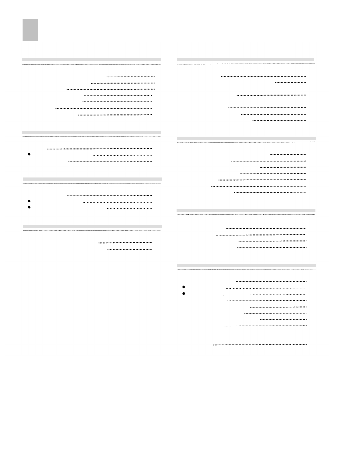
Contents
Before Use
Controls and Connection Sockets
Infra-red Remote Controller
Editing Controller
Remote Controller Setup
Editing Controller Setup
Connections
Inserting the Cassette
Basic Operations
Playback
Other Playback Functions
Manual Recording
Advanced Operations
Search Functions
Index Search System
Photoshot Index Search System
14
15
16
11
11
13
13
17
17
17
Preparations for Editing
4
7
9
Editing Functions
Connecting with a Digital Video Camera
Connecting Two Digital Video Cassette Recorders
(Using Two AG-DV2000)
Connecting an S-VHS (VHS) VCR
with an Edit Socket
Initial Settings for Editing
Creating the Tapes For Editing
22
24
26
28
30
33
For Quick Editing
Editing when Not Using an Edit Cable
One-Touch Assemble
One-Touch Insert/Audio Dubbing
One-Touch Audio Mixing
Manual Copying
Manual Insert
Manual Audio Dubbing
34
36
38
40
42
44
46
Program Editing
Various Settings
Setting the Clock of Your VCR
Settings Using On Screen Display
18
19
Program Assemble
Program Insert
Program Audio Dubbing
Other Editing Functions
Helpful Hints
Edit Timing Adjustment
Program Editing
Manual Editing
Glossary of Terms
On Screen Display Messages
Before Requesting Service
Flow Chart for On Screen Display
Usage Precautions
Specifications
48
52
56
60
62
62
64
65
67
68
70
74
76
3
Page 4
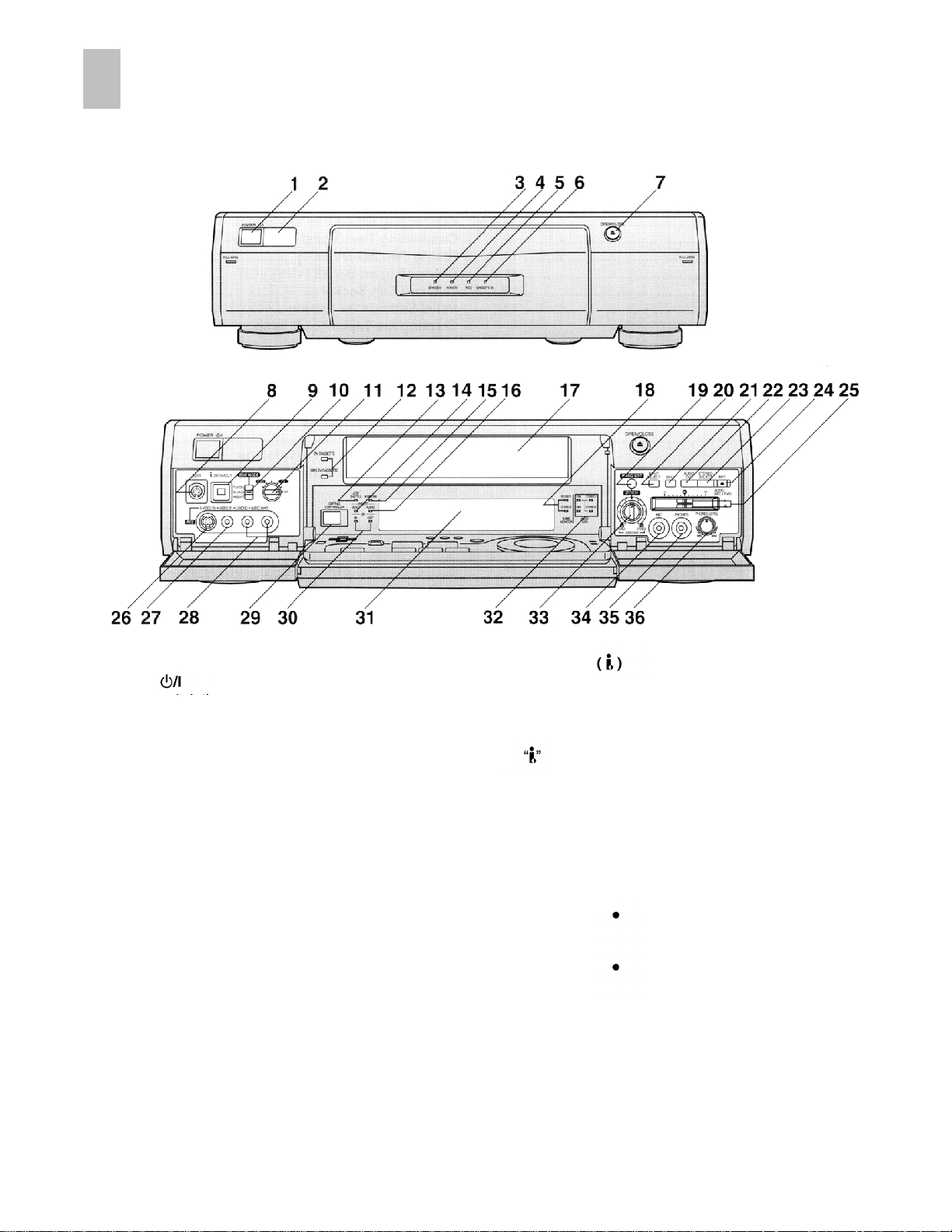
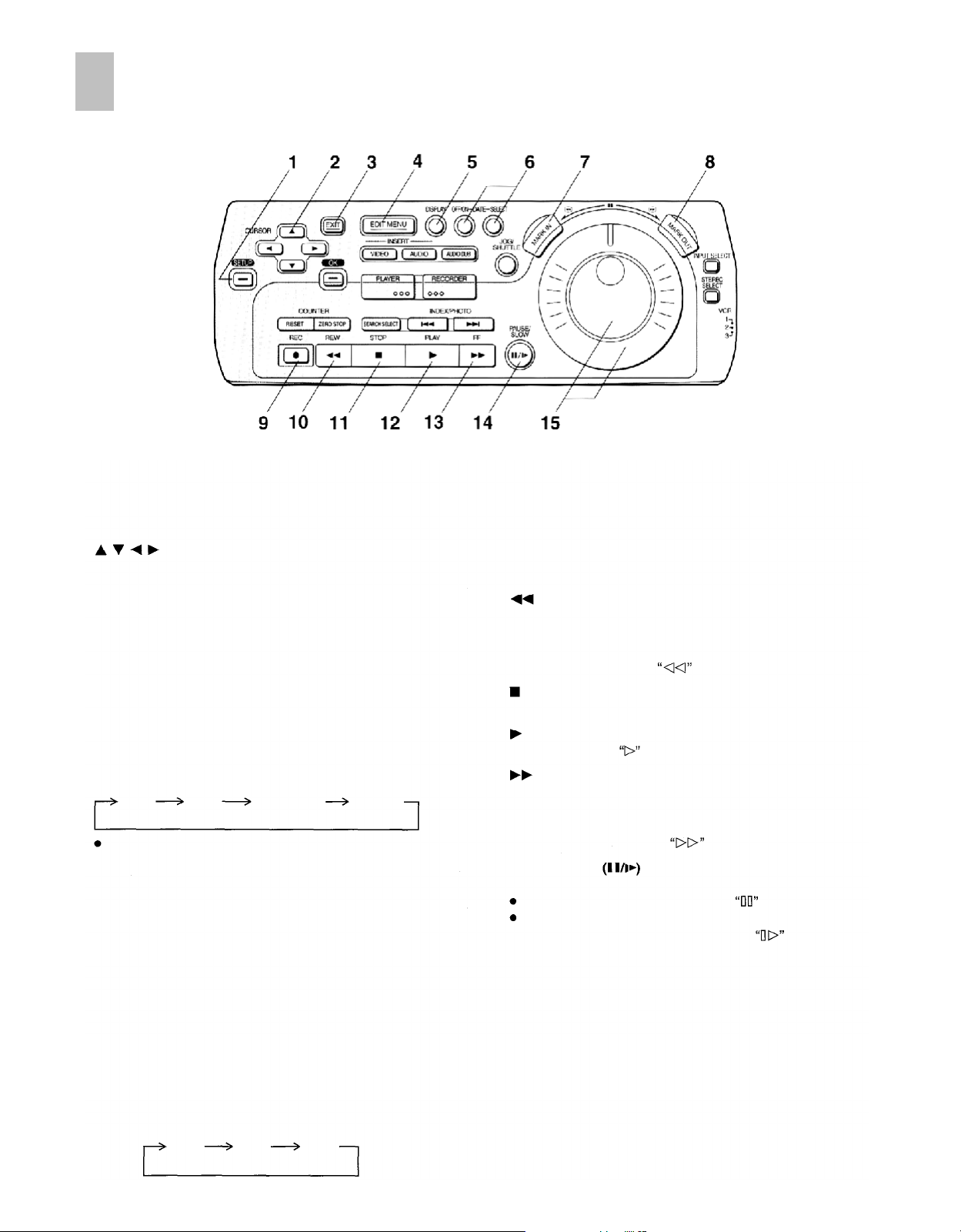
Control and Connection Sockets
This section gives a detailed explanation of the function of each button, switch and connection socket.
FRONT
1
POWER
Press to switch the VCR from on to standby mode or
vice versa. In standby mode, the unit is still connected to
the mains.
2
Infra-red Remote Control Receiver Window
STANDBY Indicator
3
This indicator is lit when main lead is connected and the
power is off.
POWER Indicator
4
This indicator is lit when the power is on.
REC Indicator
5
This indicator is lit when recording is in progress.
CASSETTE IN Indicator
6
This indicator is lit when a cassette is inserted.
OPEN/CLOSE
7
Press to open the front panel or to open/close the
cassette tray.
8
EDIT
By connecting a movie camera or VCR with an EDIT
socket to this socket via an Edit cable, various kinds of
editing functions can be performed more quickly and
efficiently between two VCRs or between a VCR and a
movie camera.
9 DV IN/OUT
To connect the DV cable to digital video equipment with
IEEE 1394-1995 compatible DV terminal.
"i.LINK” is the name of the connector in accordance with
the International Standard IEEE1394-1995.
is the logo marked on products conforming with the
“i.LINK” specifications. For further details on the DV
terminal, refer to the Glossary of Terms on page 66.
10 EDIT MODE
PLAYER:
RECORDER:
PASSIVE:
11 EDIT CONTROL
To select a connected component when another
component is to be connected for editing, etc.
12 DV CASSETTE/MINI CASSETTE Indicators
This indicator corresponds to the size of the cassette
inserted is lit.
When this VCR is used as the playback
VCR during editing operations.
When this VCR is used as the recording
VCR during editing operations.
Normally set at this position.
When operating this VCR using another
VCR or an editing controller.
The picture quality best suited for
editing is selected.
4
Page 5
13
JOG/SHUTTLE Indicator
While this display is lit, the unit is set to the Jog/Shuttle
mode.
Check that the display is lit before proceeding with a
jog or shuttle operation.
The display is automatically turned off if no operation
is performed.
14
VIDEO INSERT Indicator
This indicator is lit when the video insert editing is
performed.
AUDIO DUB Indicator
15
This indicator is lit when the Audio Dubbing or Audio
Mixing is performed.
AUDIO INSERT Indicator
16
This indicator is lit when the audio insert editing is
performed.
1718Cassette Tray
The audio track cannot be selected during the
playback of a tape recorded in the 16bit audio mode.
When INPUT SELECT is set to DV IN and a 12bit
audio mode input signal is being received, the audio
track can be selected by STEREO SELECT at any
time.
24 REC
To start recording.
25 AUDIO REC LEVEL
To adjust the audio recording level to peak at +4 dB on
the recording level indicator.
When INPUT SELECT is set to DV IN the audio
recording level cannot be adjusted.
S-VIDEO IN (AV2)
26
To connect the S-Video cable to a movie camera or to
another VCR that has an S-Video output socket.
If an S-Video cable is connected, other video input
(AV2) is automatically switched off.
Indicators for AUDIO MONITOR
The audio track selected by
(This applies only to a tape recorded in the 12 bit audio
mode.)
MIXING EDIT
19
For Mixing Editing.
INPUT SELECT
20
To select the A1, A2 or DV IN external recording source.
21
SP/LP
To select the desired tape speed for recording.
22
AUDIO OUT
To select the desired sound mode.
When this button is pressed, the audio output mode
changes as follows.
Stereo
The Left(L) and Right(R) Indicators shown which sound
mode is selected in the following way.
Stereo:
Left:
Right:
STEREO SELECT
23
To select the audio track (STEREO1 audio and/or
STEREO2 audio) on a tape which was recorded in the
12bit audio mode. During playback, each time the button
is pressed, the sound changes as follows:
The L Indicator appears.
The R Indicator appears.
STEREO1
Left
Both the L and R Indicators appear.
STEREO2
STEREO SELECT
Right
STEREO1
STEREO2
(MIX)
lights.
27 VIDEO IN (AV2)
To connect the video cable to a movie camera or to
another VCR.
28
AUDIO IN (AV2)
To connect the audio cable to a movie camera or to
another VCR.
EDITING CONTROLLER Socket
29
When using the editing controller separate from the main
unit, remove the modular cap and then connect the
editing controller cable.
DV IN/OUT Indicators
30
DV IN:
DV OUT:
31
Display
Indicators for AUDIO DATA
32
Displays the audio data that is to be recorded, or the
audio data on a tape that has already been recorded.
The audio recording mode can be set in the SET UP
MENU.
12bit-STEREO1 : To play back a tape that is recorded in
12bit-STERE02: To play back a STEREO2 audio tape
16bit :
This indicator is lit when INPUT SELECT is
set to “DV IN”.
This indicator is lit when a playback operation
is performed using this VCR or when INPUT
SELECT
is set to other than “DV IN”.
12bit audio mode.
recorded in the 12bit audio mode.
To play back a tape that is recorded in
16bit audio mode.
5
Page 6
33 AUDIO MIX Level
During the Audio Mixing function:
To adjust the volume of the original audio
(STEREO1).
During playback of a tape recorded in the 12bit audio
mode:
To adjust the mix balance between the
STEREO1 and STEREO2 audio.
34 MIC
To connect to a microphone for recording. Once
connected, this socket has priority.
35 PHONES
To connect stereo headphones.
36 PHONES LEVEL
For adjusting the volume level of connected stereo
headphones.
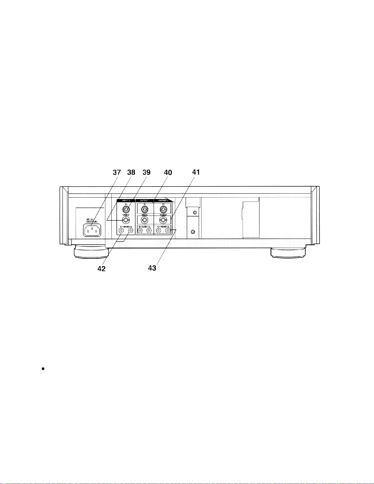
REAR
37 AC IN~
To connect to the main power supply.
38 VIDEO IN (INPUT1)
To connect the video cable (BNC) to a movie camera or
to another VCR.
39 S-VIDEO IN (INPUT1)
To connect the S-Video cable to a movie camera or to
another VCR that has an S-Video output socket.
If an S-Video cable is connected, other video input
(INPUT1) is automatically switched off.
40 S-VIDEO OUT (OUTPUT1/2)
To connect the S-Video cable to a monitor or another
VCR that has an S-Video input socket.
41 VIDEO OUT (OUTPUT1/2)
To connect the video cable (BNC) to a monitor or to
another VCR.
42 AUDIO IN (INPUT1)
To connect the audio cable to a movie camera or to
another VCR.
43 AUDIO OUT (OUTPUT1/2)
To connect the audio cable to a stereo audio system.
6
Page 7
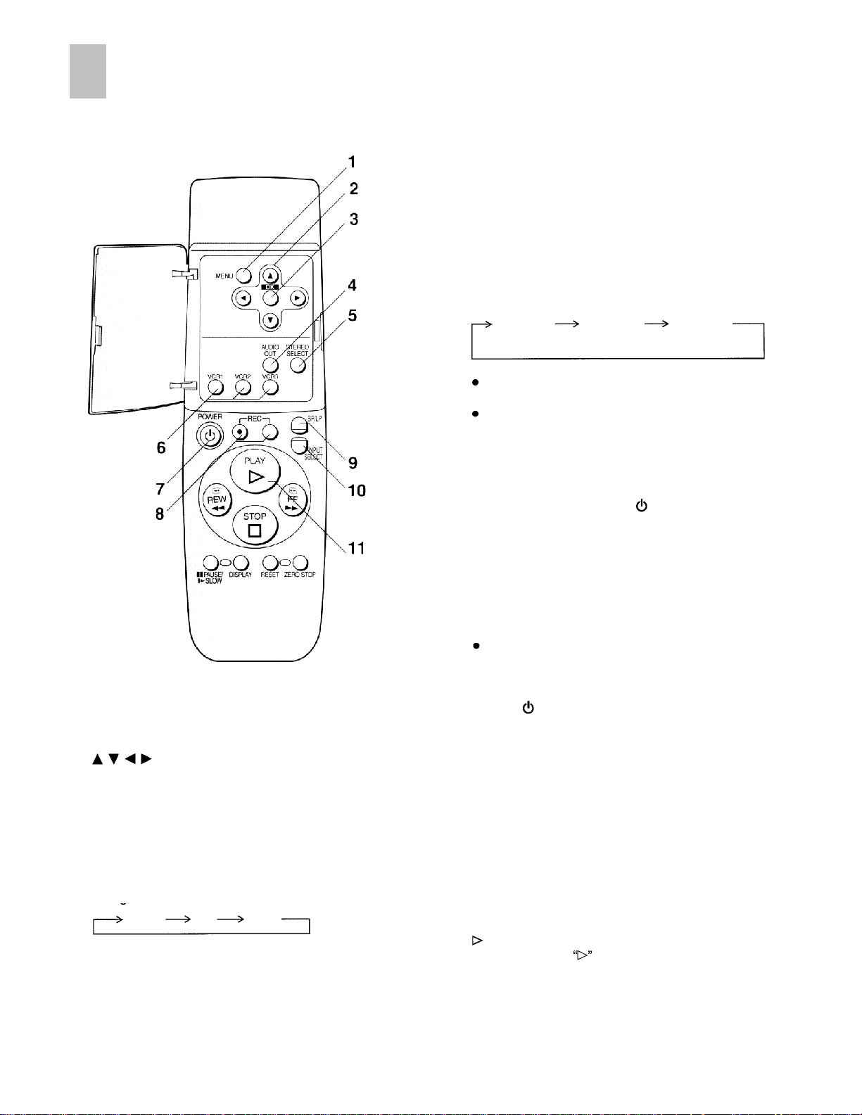
Infra-red Remote Controller
1
MENU
To make the On Screen Display Main menu appear on
the monitor screen.
2
To make selections from the On Screen Display.
3
To confirm the selection, or to store.
The Left(L) and Right(R) Indicators shown which sound
mode is selected in the following way.
Stereo:
Left:
Right:
5
STEREO SELECT
To select the audio track (STEREO1 audio and/or
STEREO2 audio) on a tape which was recorded in the
12bit audio mode. During playback, each time the button
is pressed, the sound changes as follows:
The audio track cannot be selected during the
playback of a tape recorded in the 16bit audio mode.
When INPUT SELECT is set to DV IN and a 12bit
audio mode input signal is being received, the audio
track can be selected by STEREO SELECT at any
time.
6
VCR1/2/3
While holding down
buttons to select the remote control
VCR1 :
VCR2:
VCR3:
When the VCR’s remote control mode has been
switched, select the same remote control mode on the
editing controller as well.
7
POWER
Press to switch the unit from on to standby mode or vice
versa. In standby mode, the unit is still connected to the
mains.
8OKREC
To start recording.
Press both buttons at the same time.
Both the L and R Indicators appear.
The L Indicator appears.
The R Indicator appears.
STEREO1
STEREO2
POWER
Set this position on both the VCR and
remote controller for normal use with one
VCR.
Set this position when using two
Panasonic VCRs.
Set this position when using three
Panasonic VCRs.
STEREO1
STEREO2
(MIX)
press one of these
mode.
4
AUDIO OUT
To select the desired sound mode.
When this button is pressed, the audio output mode
changes as follows.
Stereo
Left
Right
SP/LP
9
To select the desired tape speed for recording.
10 INPUT SELECT
To select the Al, A2 or DV IN external recording source.
11
(PLAY)
To start playback.
is lit during playback.
7
Page 8
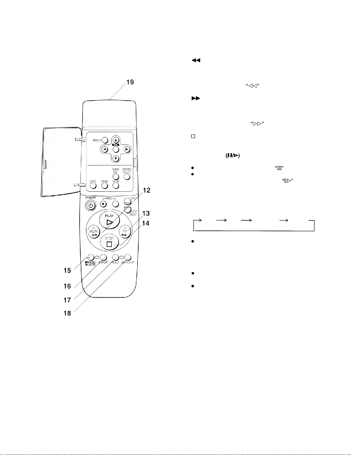
12
(REW)
In the stop mode: To rewind the tape.
In the playback mode:
In the rewind mode:
To search backward for a scene,
To view the video.
is lit during rewind.
13
14
15 PAUSE/SLOW
16 DISPLAY
17 RESET
(FF)
In the stop mode:
In the playback mode:
In the fast forward mode: To view the video.
(STOP)
To stop playback or recording.
During playback:
When pressed once: Still picture.
When pressed for 2 seconds or more:
During recording:
To change the VCR display indication as follows:
Clock
The time code frame values are not displayed on the
main unit’s VCR display.
To reset the tape counter (elapsed time) to “0:00.00”.
The tape counter is automatically reset to “0:00.00”
when a video cassette is inserted.
It is not possible to reset the Time code to
“0h00m00s00f” using RESET.
Time
Code
To fast forward the tape.
To search forward for a scene.
is lit during fast forward.
is lit.
Slow playback. is lit.
To pause recording.
Remaining
Tape Time
Counter
18 ZERO STOP
For the zero stop function.
19 Infra-red Transmitter
8
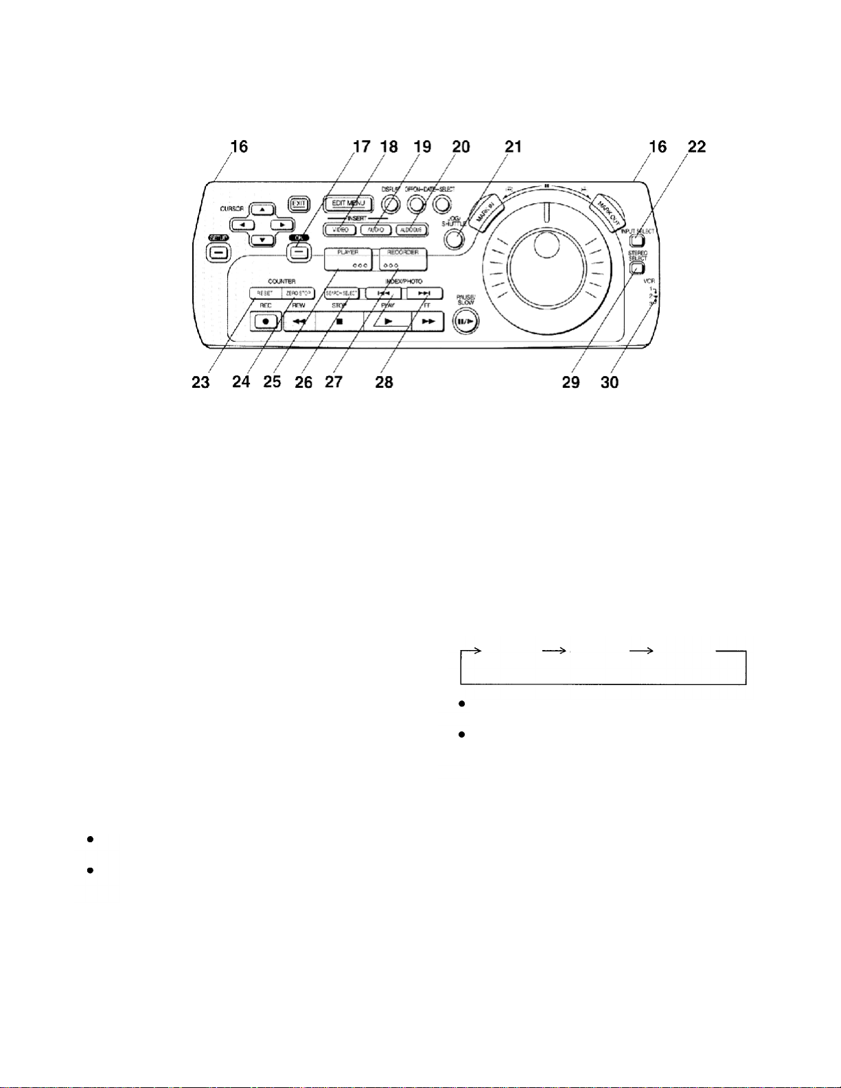
Page 9
Editing Controller
1
SET UP
To make the SET UP screen appear on the monitor
screen. When the SET UP screen is displayed, use this
button to return to the previous screen.
2
To make selections from the SET UP or EDIT MENU
screen. (When the SET UP or EDIT MENU screen is
displayed.)
3
EXIT
To exit the SET UP or EDIT MENU screen.
4
EDIT MENU
To make the EDIT MENU screen appear on the monitor
screen, and to return to the previous screen. This button
is also used to stop editing functions using the EDIT
MENU screen.
5
DISPLAY
To change the VCR display indication as follows:
Clock
The time code frame values are not displayed on the
main unit’s VCR display.
DATE-OFF/ON, DATE-SELECT
6
When pictures are recorded using this VCR or a
Panasonic Digital Video Camera, the date and time of
the recording are automatically recorded onto the tape’s
sub code track.
This button is used to select the information to be
displayed on the On Screen Display.
DATE-OFF/ON:
DATE-SELECT:
(CURSOR)
Time
Code
To make the Date/Time indication appear on the
monitor screen.
To change the indication to be displayed on the
monitor screen as follows:
Remaining
Tape Time
Counter
7
MARK IN
To set edit start points for Program Editing.
8
MARK OUT
To set edit end points for Program Editing.
REC
9
To start recording.
(REW)
10
In the stop mode:
In the playback mode: To search backward for a scene.
In the rewind mode:
11
(STOP)
To stop playback or recording.
(PLAY)
12
To start playback.
13
14 PAUSE/SLOW
15 Jog Dial/Shuttle Ring
(FF)
In the stop mode:
In the playback mode:
In the fast forward mode: To view the video.
During playback:
When pressed once: Still picture.
When pressed for 2 seconds or more:
During recording:
Jog Dial (inner dial):
Operate after pressing JOG/SHUTTLE to switch to
the Jog/shuttle mode.
To locate any desired field with utmost precision.
Shuttle Ring (outer ring):
Operate after pressing JOG/SHUTTLE to switch to
the Jog/shuttle mode.
To adjust playback speed backward or forward.
To rewind the tape.
To view the video.
is lit during rewind.
is lit during playback.
To fast forward the tape.
To search forward for a scene.
is lit during fast forward.
is lit.
Slow playback.
To pause recording.
is lit.
Date
Time
Date
Time
9
Page 10
Infra-red Transmitter
16
OK
17
To start Manual editing and to store the selection on the
SET UP or EDIT MENU screen.
VIDEO INSERT
18
For the Video Insert function and the AV Insert function.
AUDIO INSERT
19
For the Audio Insert function and the AV Insert function.
AUDIO DUB
20
For the Audio Dubbing function or the Audio Mixing
function.
21
JOG/SHUTTLE
To switch to the Jog/Shuttle mode. When the button is
pressed, it lights and the VCR enters the Jog/Shuttle
mode.
In the stop mode: Still picture (Jog/Shuttle mode).
During playback: Still picture (Jog/Shuttle mode).
22
INPUT SELECT
To select the A1, A2 or DV IN external recording source.
RESET
23
To reset the tape counter (elapsed time) to “0:00.00”.
The tape counter is automatically reset to “0:00.00”.
when a video cassette is inserted.
It is not possible to reset the Time code to
“0h00m00s00f” using RESET.
24 ZERO STOP
For the zero stop function.
26 SEARCH SELECT
To search for a recorded program using the index/
photoshot index search.
27 RECORDER
To operate the recording VCR.
28 INDEX/PHOTO
For the index/photoshot index search function.
29 STEREO SELECT
To select the audio track (STEREO1 audio and/or
STEREO2 audio) on a tape which was recorded in the
12bit audio mode. During playback, each time the button
is pressed, the sound changes as follows:
STEREO1
The audio track cannot be selected during the
playback of a tape recorded in the 16bit audio mode.
When INPUT SELECT is set to DV IN, the audio track
can be selected by STEREO SELECT at any time: it
does not have to be during playback.
30 VCR1/2/3
To select the remote control mode. The selected mode
appears on the remote controller display.
VCR1 :
VCR2:
VCR3:
STEREO2
Set this position on both the VCR and
remote controller for normal use with one
VCR.
Set this position when using two
Panasonic VCRs.
Set this position when using three
Panasonic VCRs.
STEREO1
STEREO2
(MIX)
25 PLAYER
10
To operate the playback unit.
Note:
While in the editing mode the VCR’s Time code or tape
counter display cannot be changed.
Page 11
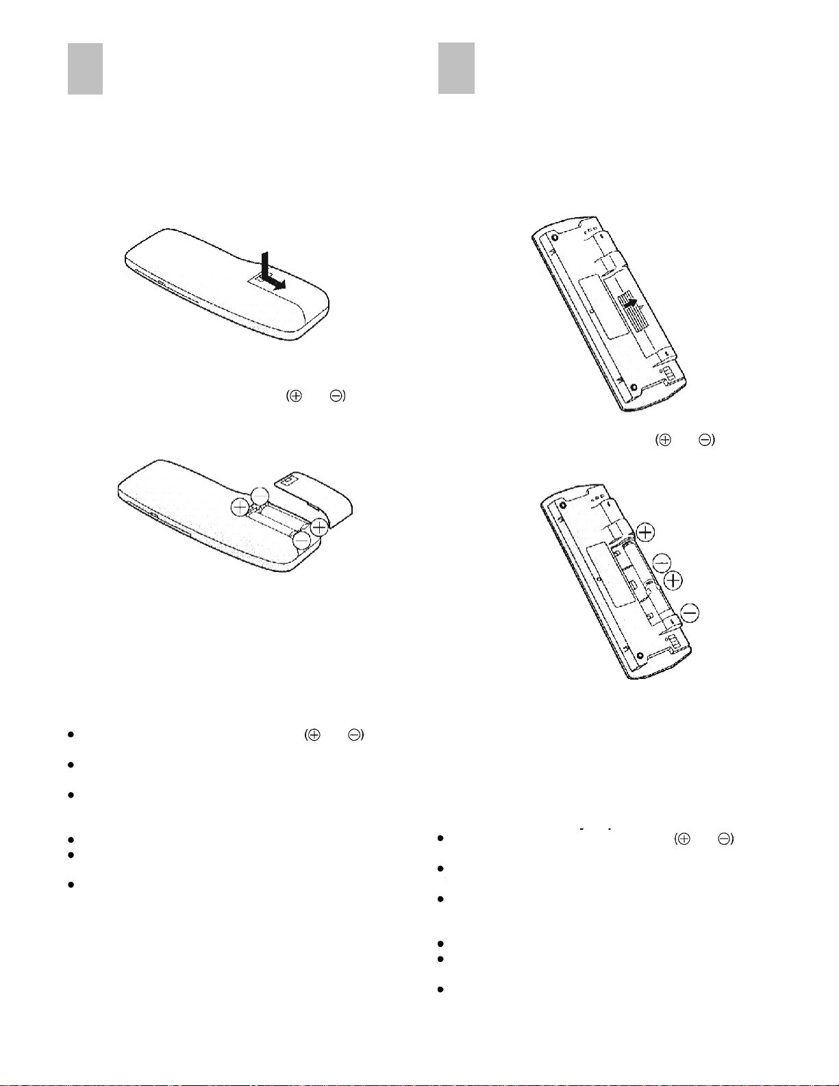
Remote Controller
Editing Controller
Setup
Installing the Batteries
1
To remove the cover, slide it in the direction of the arrow
while pressing down.
2
Load the batteries with their polarity
correctly.
and
aligned
Set Up
Installing the Batteries
1 To remove the cover, slide it in the direction of the arrow
while pressing down.
2
Load the batteries with their polarity
correctly.
and
aligned
3
Slide the cover back on.
Power Source for the Remote Controller
The remote controller is powered by 2 AA, UM3 or R6 size
batteries. The life of the batteries is about one year, although
this depends on the frequency of use.
Precautions for Battery Replacement
Load the new batteries with their polarity
aligned correctly.
Do not apply heat to the batteries, or an internal shortcircuit may occur.
If you do not intend to use the remote controller for a long
period of time, remove the batteries and store them in a
cool, dry place.
Remove spent batteries immediately and dispose of them.
Do not use an old and a new battery together, and never
use an alkaline battery with a manganese battery.
Do not use rechargeable batteries.
and
3
Slide the cover back on.
Power Source for the Editing Controller
The editing controller is powered by 2 AA, UM3 or R6 size
batteries. The life of the batteries is about one year, although
this depends on the frequency of use.
Precautions for Battery Replacement
Load the new batteries with their polarity
aligned correctly.
Do not apply heat to the batteries, or an internal shortcircuit may occur.
If you do not intend to use the editing controller for a long
period of time, remove the batteries and store them in a
cool, dry place.
Remove spent batteries immediately and dispose of them.
Do not use an old and a new battery together, and never
use an alkaline battery with a manganese battery.
Do not use rechargeable batteries.
and
11
Page 12
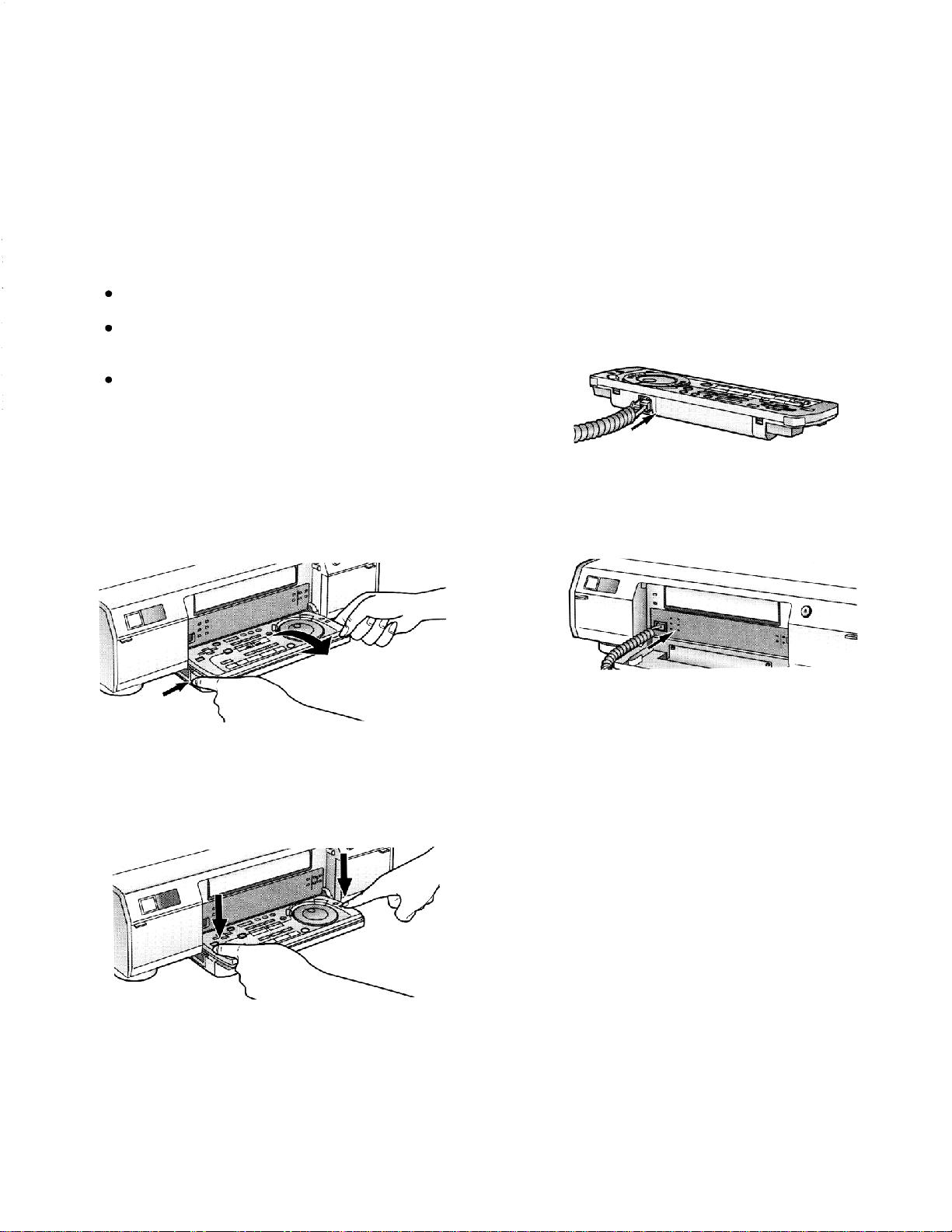
Operating
Controller
the Editing
The Editing controller can be operated in any of the
following 3 ways:
It can be operated while remaining attached to the
main unit.
Its batteries can be loaded, and it can be separated
from the main unit and operated as the remote
controller.
It can be separated from the main unit, connected
using the accessory editing controller cable and
operated as the remote controller.
How to separate the editing controller
While pressing the buttons at the left and right of the
main unit’s front panel, remove the editing controller with
both hands.
When connecting the editing controller to the
video unit using the editing controller cable
1
Remove the cover over the controller socket on the rear
panel of the editing controller, and insert the plug at one
end of the editing controller cable into this socket until it
clicks into position.
2
Remove the modular cap over the unit’s controller
socket, and insert the plug at the other end of the editing
controller cable into this socket until it clicks into position.
How to attach the editing controller
Push down on the editing controller until the areas
around the left and right buttons on the unit’s front panel
click into position.
When using the editing controller as a remote
controller
As a remote controller, the editing controller can be
operated at a distance up to about 3 m in front and up to
an angle of up to about 30 degrees to the left or right of
centre. (This range changes in accordance with the
ambient brightness.)
Note:
When the VCR’s remote control mode has been switched,
switch the remote control mode on the editing controller as
well.
12
Page 13
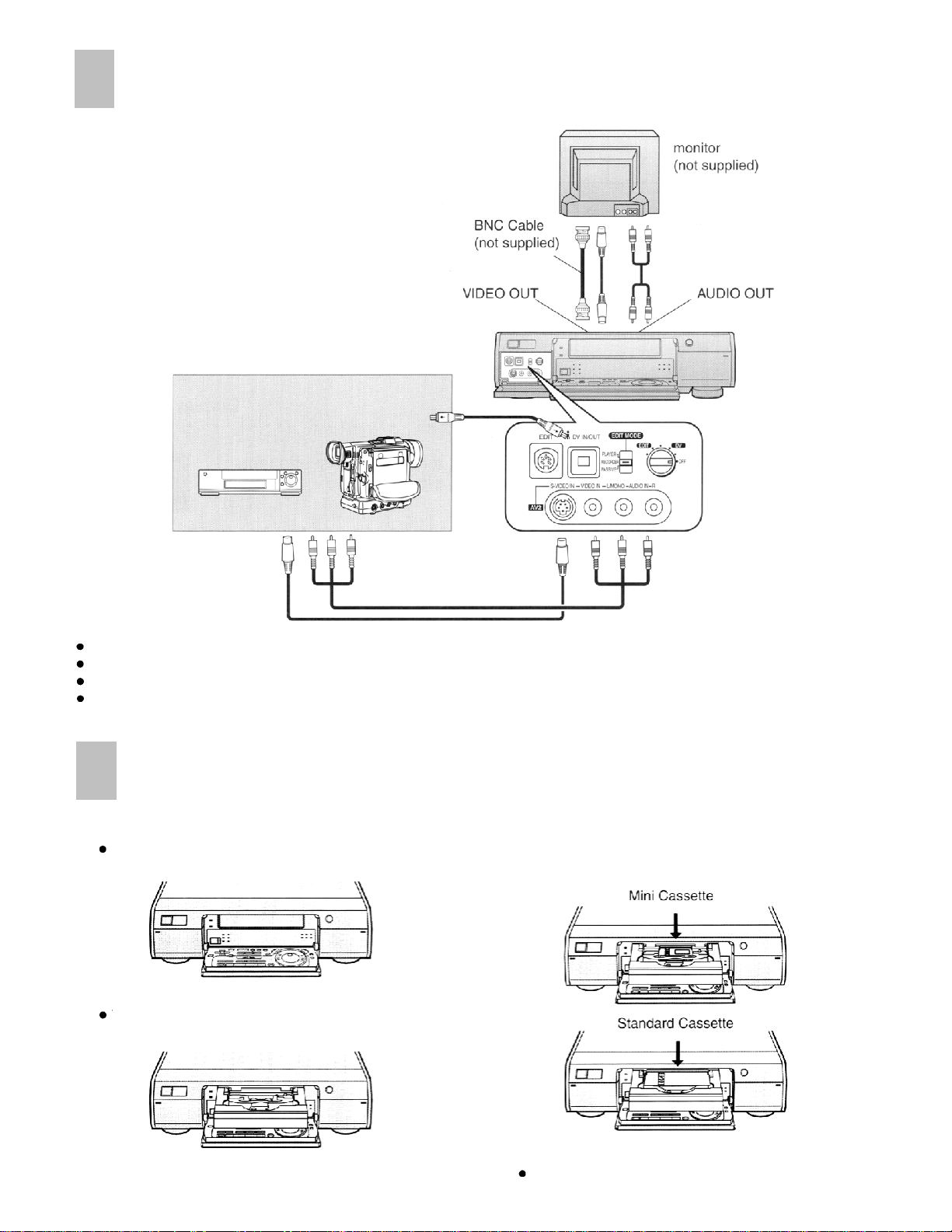
Connections
Use AV cables to connect the input sockets on this unit with the output sockets on the video equipment.
Press INPUT SELECT on this unit so that A1, A2 or DV IN is selected.
When using the BNC socket, use a BNC-PHONO conversion adapter (sold separately).
If the video equipment is connected to this unit via an S-VIDEO cable, the video signal on the S-VIDEO cable takes priority.
If the video equipment does not have an S-VIDEO socket do not connect the S-VIDEO cable to this unit.
Inserting the Cassette
3
1 Press OPEN/CLOSE.
The front panel opens.
2 Press OPEN/CLOSE again.
The cassette tray is extended.
Align the cassette with the cassette guide and place it on the
tray while ensuring that the side of the cassette with the tape
exposed is facing up and the label side is turned toward you.
4 Press OPEN/CLOSE.
The cassette tray is retracted inside the video unit.
13
Page 14
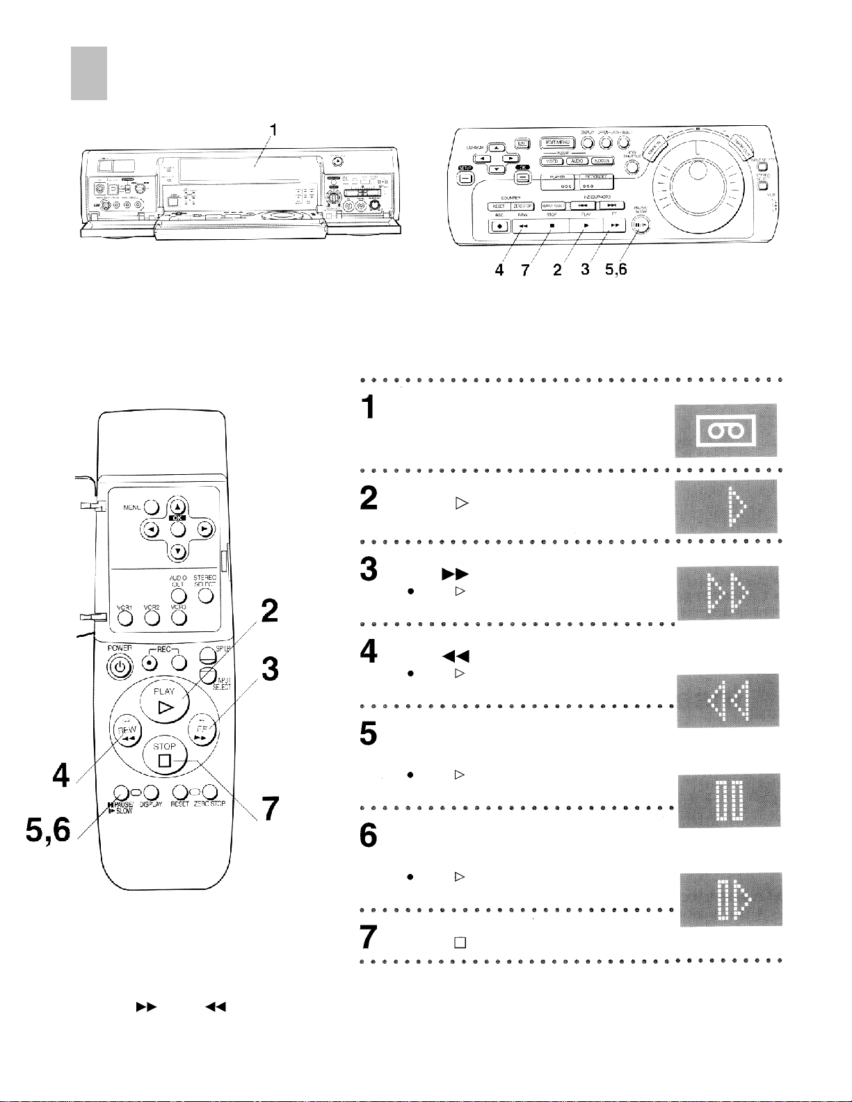
Playback
Operations
Insert a recorded cassette tape
(page 13).
Press
Tap
Press
to normal playback.
Tap
Press
to normal playback.
Press PAUSE/SLOW to view a still
picture.
Press
to continue normal playback.
Display Symbols
(PLAY) to start playback.
(FF) to search forward.
(PLAY) to change back
(REW) to search backward.
(PLAY) to change back
(PLAY) or PAUSE/SLOW
Note:
If you keep
operation returns to normal playback when the button is released.
14
(FF) or
(REW) pressed in step 3 or 4, search playback is activated while the button is pressed, and
Keep PAUSE/SLOW pressed for 2
seconds or more to view a slow motion picture.
Press
playback.
Press
(PLAY) to continue normal
(STOP) to stop the picture.
Page 15
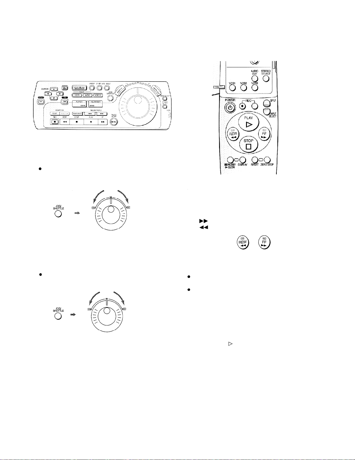
Other Playback Functions
To Change the Playback Speed
1
Press
JOG/SHUTTLE
The button on the editing controller is lit.
2 Rotate Shuttle Ring.
Backward
on the editing controller.
Forward
To View the Video During Fast Forward or
Rewind
Keep
Keep
(FF) pressed during fast forward.
(REW) pressed during rewind.
To Locate the Desired Picture Exactly
1
Press
JOG/SHUTTLE
The button on the editing controller is lit.
2 Turn Jog dial.
Backward
on the editing controller.
Forward
To Return to a Specified Scene
After playback, press
The tape will be rewound or fast forwarded to 0:00.00
approximately.
During Time code display, this function will not work.
ZERO STOP
in the stop mode.
Automatic Playback
When a cassette with the opened record prevention tab is
inserted, the VCR starts playback automatically.
VCR-off Playback
When the VCR is off, an inserted cassette can be played
back by pressing
(PLAY).
Automatic Rewinding
When the tape reaches the end during recording or
playback, it will automatically be rewound to the beginning.
Note:
Cue, review or slow playback will be automatically canceled
after 10 minutes, and still playback after 5 minutes.
15
Page 16
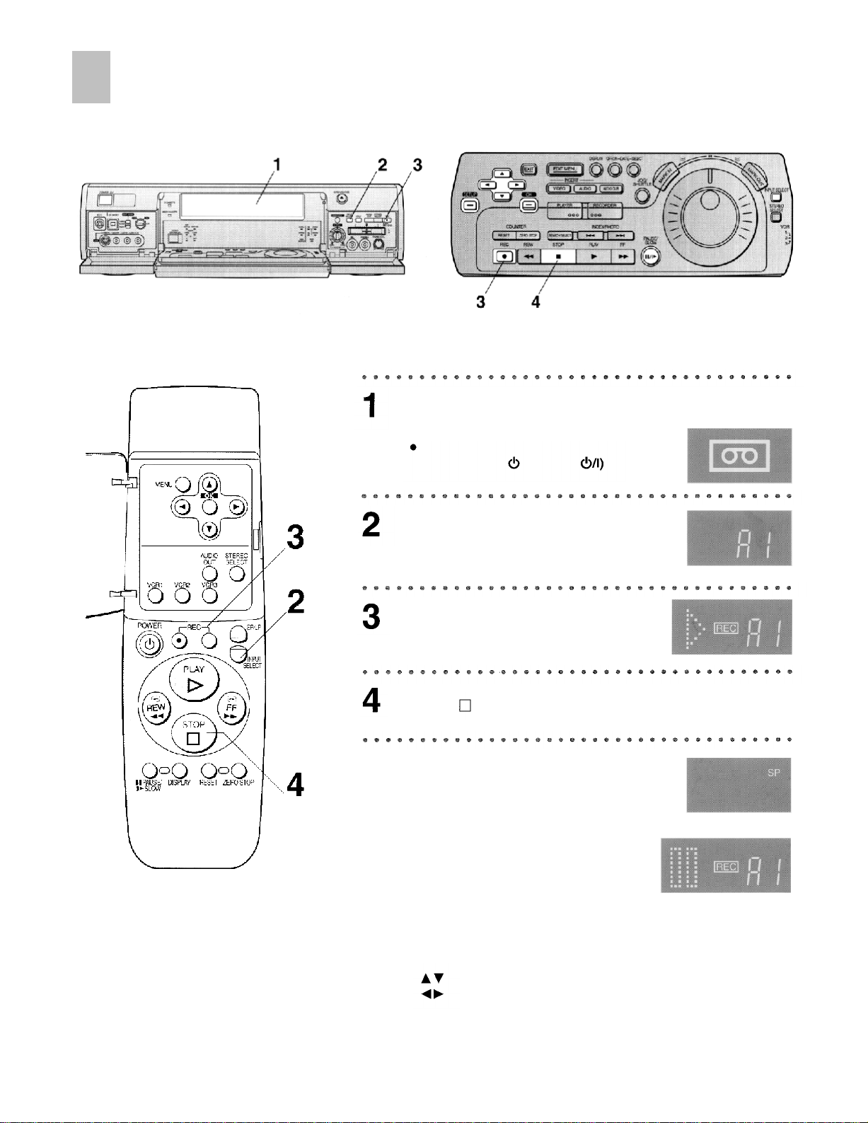
Manual Recording
Operations
Insert a video cassette with the closed record
prevention tab (page 13).
If it has already been inserted,
press POWER (POWER
the VCR on.
Press INPUT SELECT on this unit
so that A1, A2 or DV IN.
Press REC to start recording.
Press
Display Symbols
)
to turn
(STOP) to stop recording.
To Select the Desired Tape Speed
Press
SP/LP
before recording.
To Pause Recording
Press
PAUSE/SLOW
Press again to continue recording.
during recording.
To Select the Desired Audio Mode
Perform the procedure below using the editing controller.
1
Press
SET UP.
select
, select
Audio Mode
12bit
2 Using
3 Using
For details, see Initial Settings for Editing on page 30.
Note:
A long-Mini DV cassette (SP/80 min., LP/120 min.) that was recorded by this VCR cannot be played back or recorded by a
DVCPRO or DVCPRO 50 format VCR.
16
,
or
and press
16bit,
OK.
then press
OK.
Page 17
Search Functions
Index Search System
It is easy to find the beginning of each recording because a
special index signal is recorded at the start of each recorded
segment on the tape.
For example:
Searching for the 2nd recorded segment in the forward
direction.
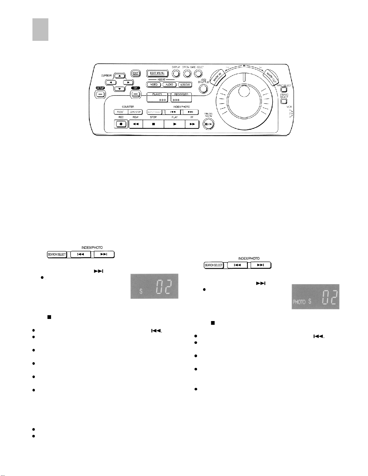
1
Press SEARCH SELECT so that “S - -” appears on the
VCR display.
(This operation is performed while the VCR is in the stop
mode or normal playback mode.)
2 Press INDEX/PHOTO
After finding the specific
recorded segment, playback
starts automatically.
To stop the operation at any time
Press
Recording Index Signals
Index signals are recorded in the following cases.
(STOP).
For the reverse direction, press
Up to 20 index signals can be searched for in either
direction.
When the opposite INDEX/PHOTO is pressed, the number
shall be decreased until 1 is reached.
The figure on the display is reduced by 1 each time an
index signal is located.
The INDEX search function can only work correctly if the
index signals are spaced at least 5 minutes apart.
Repeat the procedure if the index signal for the specified
number is not found.
When a recording is started by pressing REC.
When REC on the remote controller or the editing
controller is pressed during recording.
twice.
Display Symbols
INDEX/PHOTO
Photoshot Index Search
System
Photo shot index signals are automatically recorded when a
Panasonic Digital Video Camera is used for Photo shot
Mode. Photo shot images are searched using these signals,
and when such an image is located, the image is played
back as a still picture.
For example:
Searching for the 2nd photo shot image in the forward
direction.
1
Press SEARCH SELECT so that “PHOTO S - -”
appears on the VCR display.
2 Press INDEX/PHOTO
After finding the specific image,
playback starts automatically.
To stop the operation at any time
Press
(STOP).
For the reverse direction, press
Any of up to 20 images ahead on the tape can be
designated.
When the opposite
number shall be decreased until 1 is reached.
It may not be possible to search for a particular image
properly if photo shot images have been recorded
continuously.
At every press of the corresponding button, the tape is
fast-forwarded or rewound to the next still picture recorded
in the Photoshot Mode.
After reaching the next still picture, the still picture is
played back continually together with the sound (only for
approx. 4 seconds).
INDEX/PHOTO
twice.
Display Symbols
INDEX/PHOTO
is pressed, the
17
Page 18
Setting the Clock of Your VCR
The built-in digital clock employs the 24-hour system.
Preparations
Confirm that the monitor is on and the VCR viewing
channel is selected.
Turn on the VCR and monitor.
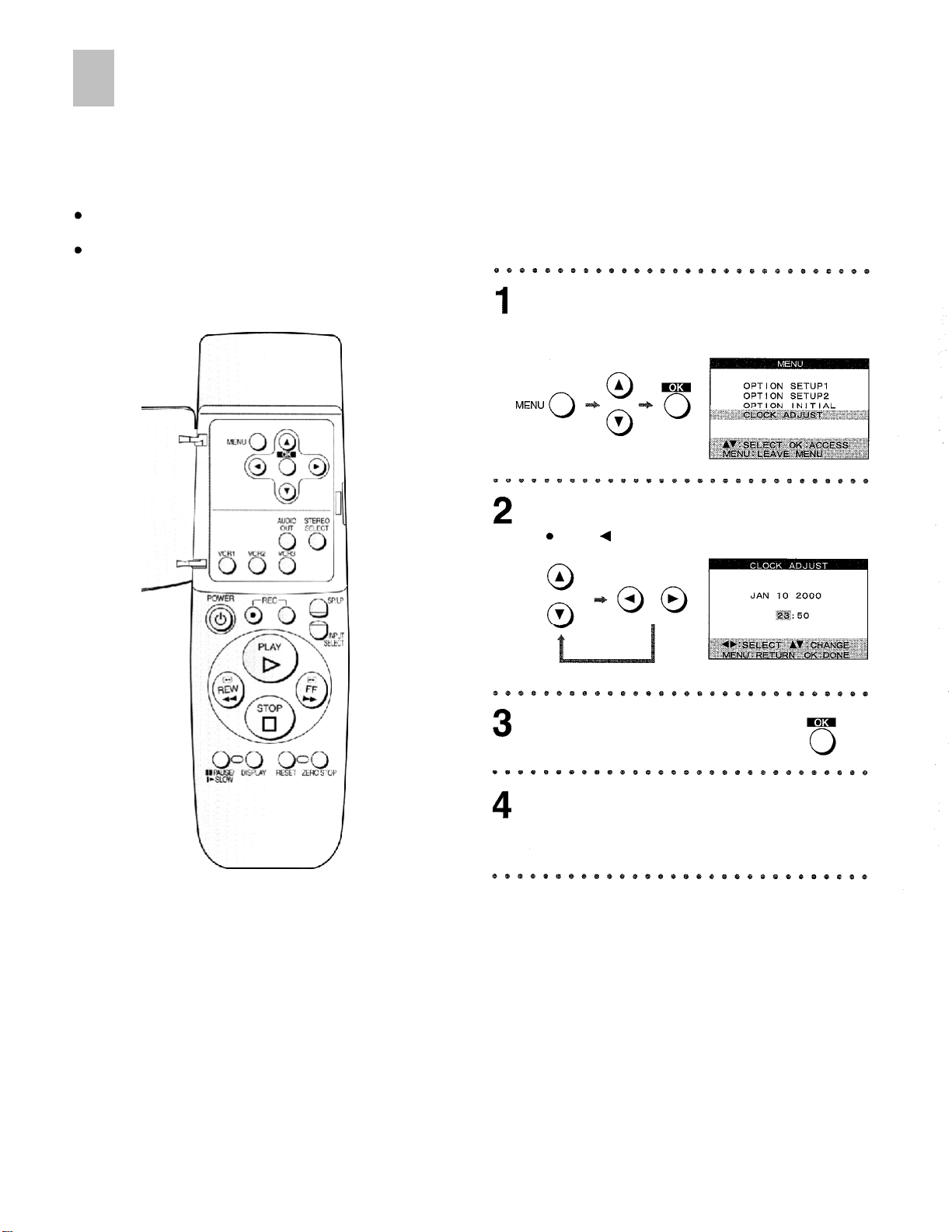
Operations
Press MENU, and then select CLOCK
ADJUST.
Set Time and Date.
Press
On Screen Display
to return to the previous item.
Press
OK
to confirm.
Press MENU to exit the On Screen
Display.
18
Page 19
Settings Using On Screen Display
The VCR indications shown on the monitor screen are
known as the On Screen Display (OSD).
This VCR allows many settings to be made at the OSD.
Preparations
Confirm that the monitor is on and the VCR viewing
channel is selected.
Turn on the VCR and monitor.
OSD Mode
1
Press
MENU,
and then select
OPTION SETUP1.
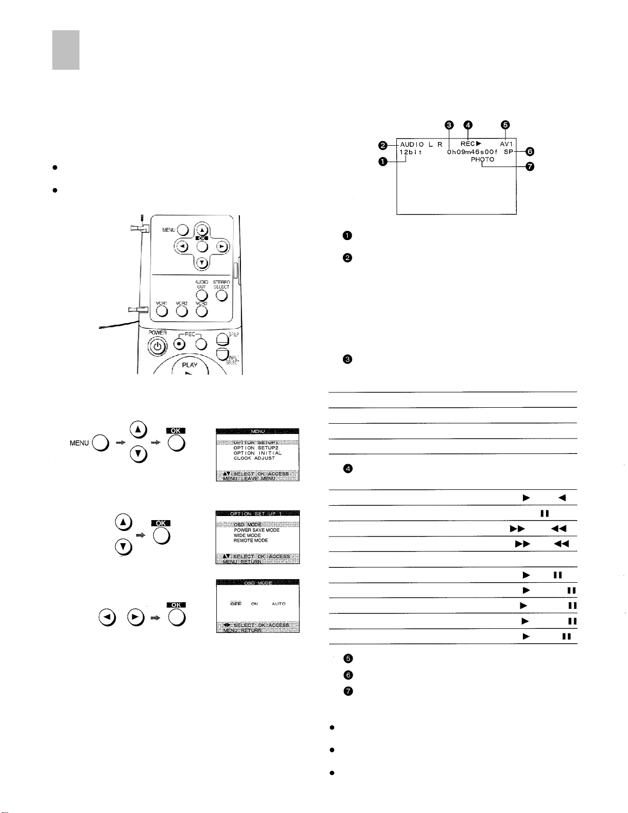
On Screen Display
To use the On Screen Display:
Audio Data indicator
Audio Output Mode Indicator
The Left (L) and Right (R) Indicators show which
sound mode is selected with AUDIO OUT
(see page 5 or 7).
Stereo:
Left:
Right:
Present time/Time code/Remaining tape time/
Tape counter/lndex/Photoshot Index Search
Present date and time
Time code
Remaining tape time
Tape counter
Index/Photoshot index Search
Both the AUDIO L and R Indicators
appear.
The AUDIO L Indicator appears.
The AUDIO R Indicator appears.
JUN 11 19:22
0h09m46s00f
REMAIN 1:16
- 1:35.47
S 02
2 Select OSD MODE.
3
Select
4
AUTO:
ON:
OFF:
Press
AUTO, ON
MENU
or
The On Screen Display will appear on the
monitor screen for a few seconds when
you operate the VCR.
The On Screen Display will always appear
on the monitor screen when you perform
the VCR.
The On Screen Display will not appear.
twice to exit the On Screen Display.
OFF.
Tape running display
Stop
Playback/Reverse Playback
Still Playback
Fast Forward/Rewind
Cue/Review
Slow/Reverse Slow Playback
Recording/Recording Pause
Video Insert/Insert Pause
Audio Insert/Insert Pause
AV Insert/Insert Pause
Audio Dubbing/Dubbing Pause
External Input Indicator
Tape speed Indicator
Index/Photoshot Index Search Indicator
Notes:
When the item
Display will not appear.
“COLOR MODE”
When
Display will not appear.
On Screen Display is not displayed when the SET UP or
EDIT MENU screen is displayed.
“OSD MODE”
is set to
is set to
PLAY /PLAY
STILL
FF
/REW
CUE
VID INS /VlD INS
AUD INS /AUD INS
A/V INS /A/V INS
A.DUB
OFF,
OFF,
the On Screen
/REV
SLOW
REC
/REC
/A.DUB
the On Screen
19
Page 20
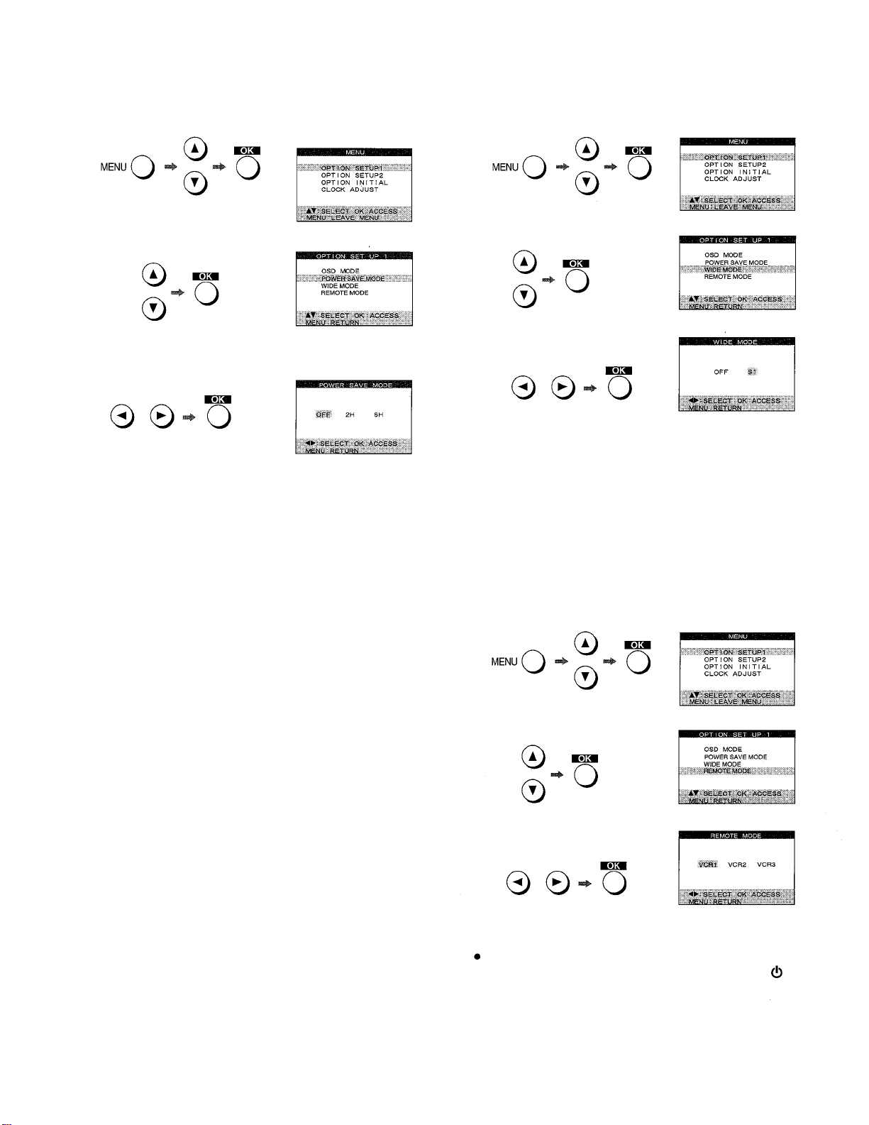
Power Save Mode
1
Press
2
3
MENU,
Select
POWER SAVE MODE.
Select
OFF, 2H
OFF:
2H:
6H:
and then select
or
6H.
This setting does not conserve power when the
VCR is off.
The VCR turns off automatically if no operation is
performed for approximately two hours.
The VCR turns off automatically if no operation is
performed for approximately six hours.
OPTION SETUP1.
On Screen Display
Wide Mode
1
Press
MENU,
2 Select WIDE MODE.
3
Select
OFF
OFF:
S1:
4
Press
MENU
and then select
or
S1.
When the S-Video input socket on the monitor
that is connected is an S-Video socket.
When the S-Video input socket on the monitor
that is connected is an S1 -Video socket.
(If a wide mode video signal is sent to the
monitor, the monitor screen size will automatically
switch to wide mode.)
twice to exit the On Screen Display.
OPTION SETUP1.
4
Press
MENU
twice to exit the On Screen Display.
To Set the Remote mode
1
Press
MENU,
2 Select REMOTE MODE.
3
Select
VCR1, VCR2
This allows the remote controller to be set for operating
VCR1, VCR2 or VCRS.
When changing the remote control mode, press
VCR1 ,VCR2
to change the remote control mode of the remote
controller. If this is not done, it will not be possible to
operate the VCR using the remote controller.
and then select
or
VCR3.
or
VCR3
while holding down
OPTION SETUP1.
POWER
20
4
Press MENU twice to exit the On Screen Display.
Page 21
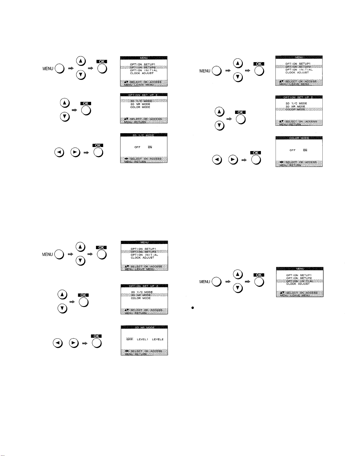
3D Y/C Mode
1
Press
MENU,
and then select
OPTION SETUPS.
To Set the Color Mode
1
Press
MENU,
and then select
OPTION SETUP2.
2 Select 3D Y/C MODE.
3
Select
OFF
or
ON.
OFF: To reduce ghosting that occurs when playing
back or recording a fast-moving video.
ON:
To record with high quality.
4
Press MENU twice to exit the On Screen Display.
3D NR Mode
1
Press
MENU,
and then select
OPTION SETUP2.
2 Select COLOR MODE.
3
Select
OFF
or
ON.
OFF:
When performing recording and playback in
black-and-white.
When performing recording and playback in color.
ON:
4
Press MENU twice to exit the On Screen Display.
Initial Setting
If you want to return the VCR to the factory-preset condition,
follow the procedure below.
1
Press
MENU,
and then select
OPTION INITIAL.
2
Select
3D NR MODE.
3
Select
OFF, LEVEL1
OFF:
LEVEL1 :
LEVEL2:
4
Press MENU twice to exit the On Screen Display.
or
LEVEL2.
To use this VCR as the playback unit
during editing.
To get better picture quality during
playback.
When there is a lot of picture noise on the
screen.
The message
bottom of the screen.
2
Press
MENU
“INITIAL COMPLETED.”
to exit the On Screen Display.
appears at the
21
Page 22
Editing Functions
Using this VCR, 4 types of
One-Touch-Edit,
3 types of
Manual Editing and 3 types of Program Editing can be
selected.
In Program Editing, after setting the edit start/end point,
editing can be performed automatically. Edit programs can
be set up to 10 scenes for each editing function (40 scenes
for Assemble editing).
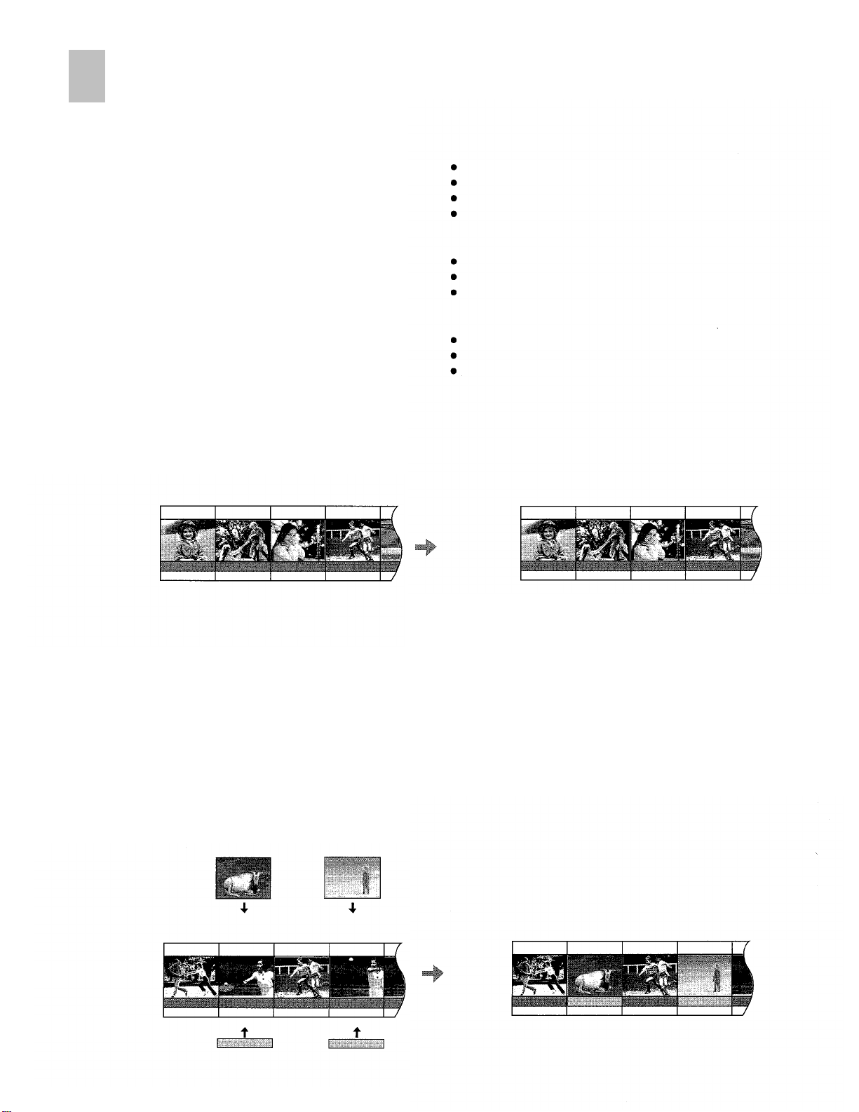
Copying
Allows the re-recording (copying) of the picture and sound
from one tape onto another tape.
Playback Unit
Subcode
Picture
One-Touch-Edit
Assemble Editing (page 36)
Insert Editing (Video, Audio, AV)
Audio Dubbing (page 38)
Audio Mixing (page 40)
Manual Editing
Copying
(page 42)
Insert Editing (Video, Audio, AV)
Audio Dubbing
(page 46)
Program Editing
Assemble Editing (page 48)
Insert Editing (Video, Audio, AV)
Audio Dubbing
(page 56)
Recording Unit
Subcode
Picture
(page 38)
(page 44)
(page 52)
Sound(STEREO1)
Sound(STEREO2)
Video Insert
Allows the partial replacement of the picture on a recorded
tape. Sound is left in its original state.
Audio Insert
Allows the partial replacement of sound on a recorded tape.
Picture is left in its original state.
AV Insert
Allows the partial replacement of the picture and sound on a
recorded tape.
Pictures from the Playback Unit
Recording VCR
Subcode
Picture
Sound(STEREO1)
Sound(STEREO2)
Performing the Copying operation on a tape that was
recorded in 12bit audio mode.
Edited Tape
Subcode
Picture
Sound(STEREO1)
Sound(STEREO2)
22
Sounds from the Playback Unit
Sound(STEREO1)
Sound(STEREO2)
Performing the AV Insert editing operation on a tape
that was recorded in 12bit audio mode.
Page 23
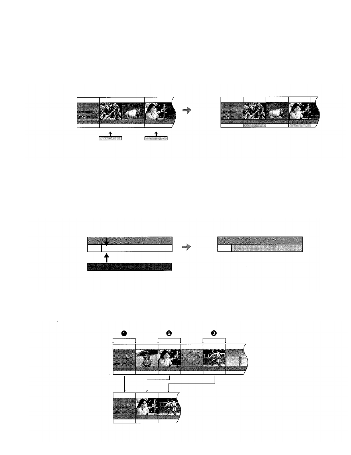
Audio Dubbing
Allows the addition of the new sound on the STEREO2 track
of a recorded tape. The original sound is left on the
STEREO1 track.
Recording VCR
Subcode
Picture
Sound(STEREO1)
Sound(STEREO2)
Sounds from the Playback Unit
Audio Mixing
Allows the mixing of the the original sound on the STEREO1
track with the new sound from the external recording source
and recording the mixed sound on the STEREO2 track of a
recorded tape. The original sound is left on the STEREO1
track.
Recording VCR
STEREO1
Sound
STEREO2
Edited Tape
Subcode
Picture
Sound(STEREO1)
Sound(STEREO2)
Performing the Audio Dubbing operation on a tape
that was recorded in 12bit audio mode.
Edited Tape
STEREO1
STEREO2
Sound from the external recording source
Assemble Editing
Allows the required scenes (picture and sound) to be picked
up from a recorded tape and recorded in any desired order
onto another tape.
Playback Unit
Edit Programmes
Subcode
Picture
Sound(STEREO1)
Sound(STEREO2)
Subcode
Picture
Sound(STEREO1)
Sound(STEREO2)
Edited Tape
Performing the Program Assemble editing
operation on a tape that was recorded in 12bit
audio mode.
23
Page 24

Connecting with a Digital Video Camera
Example for connecting Panasonic Digital Video Camera as the playback unit, when controlling the playback unit through this
unit.
Notes:
Before connecting any cables, first make sure that the
power for both units is off.
Insert a recorded cassette into the playback unit, and a
cassette with the closed record prevention tab into the VCR.
If the playback unit is connected to the recording unit via an
S-VIDEO cable, the video signal on the S-VIDEO cable
takes priority. If the playback unit does not have an SVIDEO socket do not connect the S-VIDEO cable to this
unit.
Use of an AC adaptor as the power source for the Digital
Video Camera is recommended. Doing so avoids a
situation where the camera shuts down due to low battery
power.
It is recommended that the DV cable be disconnected for
editing with INPUT SELECT set to A1 and A2. If INPUT
SELECT is set to A1 and A2 with the connections shown in
the figure left unchanged, the monitor picture may be
disturbed or noise may occur. (This has no effect on the
actual editing operations.)
When the units are connected using the DV cable and
editing is performed, some editing functions will differ
compared with when the units are connected using the AV
cable. Refer to Glossary of Terms on page 66.
24
Read the operating instructions of the Digital Video Camera.
Do not change the EDIT CONTROL or EDIT MODE settings
while performing setting or editing operations at the SET UP
or EDIT MENU screens. Be sure to quit these screens
before changing these settings.
When using a Panasonic Digital Video Camera as the
playback unit, the following editing functions can be used by
connecting the camera to this unit with a DV cable:
Copying
Video Insert
Audio Insert
Assemble
In this case, simply set INPUT SELECT to DV IN, and set
EDIT CONTROL
(This function may not operate properly with some models.)
Use Time codes for Program Editing when the playback unit
is connected to this unit via a DV cable.
When using the BNC socket, use a BNC-PHONO
conversion adapter (sold separately).
to DV.
Page 25

Playback Unit
Recording Unit
(Digital Video Camera)
Turn the power on.
Make the Time code appear on the
LCD monitor or the viewfinder.
Prepare the tape for playback.
(this unit)
Turn the power on.
Set EDIT MODE to
RECORDER.
Set EDIT CONTROL to
EDIT.
Press INPUT SELECT so that DV IN is
selected.
When pet-forming Audio Dubbing or AV Insert,
select A1 or A2.
25
Page 26

Connecting Two Digital Video Cassette Recorders (Using two AG-DV2000)
Example for connecting this unit, when controlling the playback VCR through the recording VCR.
Refer to the diagram below and connect the cables
required for the desired editing function.
Notes:
Before connecting any cables, first make sure that the
power for both VCRs is off.
Insert a recorded cassette into the playback VCR, and a
cassette with the closed record prevention tab into the VCR.
When the units are connected using the DV cable and
editing is performed, some editing functions will differ
compared with when the units are connected using the AV
cable. Refer to Glossary of Terms on page 66.
Use Time codes for program editing when the playback
VCR is connected to this unit via only a DV cable.
It is recommended that the DV cable be disconnected for
editing with INPUT SELECT set to A1 and A2. If INPUT
SELECT is set to A1 and A2 with the connections shown in
the figure left unchanged, the monitor picture may be
disturbed or noise may occur. (This has no effect on the
actual editing operations.)
Do not change the EDIT CONTROL or EDIT MODE settings
while performing setting or editing operations at the SET UP
or EDIT MENU screens. Be sure to quit these screens
before changing these settings.
26
When the connections and setting are made as shown
above, then :
The
(PLAY),
on the playback VCR or the remote controller cannot be
used to control the playback VCR directly. In order to
permit direct control, set EDIT CONTROL on the playback
VCR to
OFF.
The following editing functions can be used by connecting
the playback VCR with a DV cable:
Copying
Video Insert
Audio Insert
Assemble
In this case, simply set INPUT SELECT to DV IN, and set
EDIT CONTROL
When using the BNC socket, use a BNC-PHONO
conversion adapter (sold separately).
(FF), REC and the other such buttons
to DV
Page 27

Playback VCR
Recording VCR
Turn the power on.
Set EDIT MODE to
PASSIVE.
Set EDIT CONTROL to
EDIT.
Controlling the Recording VCR
through the Playback VCR
Follow the procedure described below:
Connect the edit cable to the EDIT socket on both
the playback VCR and the recording VCR.
Use AV cables to connect the input sockets on the
recording VCR with the output sockets on the
playback VCR.
Connect two monitors, one to each of the VCRs, so
that the screens from both VCRs can both be seen.
Set
EDIT CONTROL
the recording VCR to
Press
INPUT SELECT
select a position to which a cable is not connected.
Set
EDIT MODE
Playback VCR :
Recording VCR :
on both the playback VCR and
EDIT.
on the playback VCR and
on both VCRs as follows:
PLAYER
PASSIVE
Turn the power on.
Set the EDIT MODE to
RECORDER.
Set EDIT CONTROL to
EDIT.
Press INPUT SELECT so that DV IN is
selected.
When performing Audio Dubbing or AV Insert,
select A1 or A2.
Recording VCR
Notes:
When this connection is made, the recording VCR
cannot be controlled using the DV cable.
Although noise may appear on the screen, depending
on the connections, the noise has no effect on the
actual editing operations.
Audio Insert and AV Insert are not possible in this
configuration.
When performing editing with this connection, the
editing accuracy may be worse than when controlled
from the recording VCR.
Playback VCR
27
Page 28

Connecting an S-VHS (VHS) Video Equipment with an Edit Socket
Example for connecting an S-VHS (VHS) Video Equipment with an Edit socket as the playback unit, when controlling the
playback unit through the recording VCR (this unit).
Refer to the diagram below and connect the cables
required for the desired editing function.
Notes:
Before connecting any cables, first make sure that the
power for both units is off.
Insert a recorded cassette into the playback unit, and a
cassette with the closed record prevention tab into the VCR.
If the playback unit is connected to the recording unit via an
S-VIDEO cable, the video signal on the S-VIDEO cable
takes priority. If the playback unit does not have an SVIDEO socket do not connect the S-VIDEO cable to this
unit.
28
Read the operating instructions of the playback unit.
Do not change the EDIT CONTROL or EDIT MODE settings
while performing setting or editing operations at the SET UP
or EDIT MENU screens. Be sure to quit these screens
before changing these settings.
When using this VCR as the recording VCR, the On Screen
Display (date/time, Time Code) may scroll vertically when
still playback or slow playback are performed by the
playback VCR.
When using the BNC socket, use a BNC-PHONO
conversion adapter (sold separately).
Page 29

Playback Unit
Recording VCR
(S-VHS (VHS) Video
Equipment with an Edit socket)
Turn the power on.
Set the unit so that it is ready to be
controlled.
Read the operating instructions of the playback
unit and make the necessary settings.
(this unit)
Turn the power on.
Set EDIT MODE to
RECORDER.
Set EDIT CONTROL to
EDIT.
Press INPUT SELECT so that A2 is
selected.
If the playback unit is connected to the external
input on the rear of this unit, select A1.
Connecting this unit as the Playback
VCR to an S-VHS (VHS) VCR
Follow the procedure described below.
Connect the edit cable to the EDIT socket on both the
playback VCR and the recording VCR.
Use AV cables to connect the output sockets on this
unit with the input sockets on the S-VHS (VHS) VCR.
Connect two monitors, one to this VCR and one to the
S-VHS (VHS) VCR, so that the screens from both
VCRs can both be seen.
EDIT CONTROL
Set
Set
EDIT MODE
Press INPUT SELECT on this unit and select a
position to which a cable is not connected.
Make the necessary editing control settings for the SVHS (VHS) VCR. (Read the operating instructions of
S-VHS (VHS) VCR.)
on this unit to
on this unit to
EDIT.
PLAYER.
The Recording Unit
Note:
Audio Insert and AV Insert are not possible in this
configuration.
The Playback Unit
(this unit)
29
Page 30

Initial Settings for Editing
This VCR also allows some settings for editing to be made at the On Screen Display (OSD).
Preparations
Confirm that the monitor is on and the VCR viewing channel
is selected.
Complete necessary connections and settings.
See pages 24-29.
Search with Sound
Press
1
2
3
SET UP.
Select
Search With Sound.
On Screen Display
Select
OFF, EDIT ONLY
OFF:
EDIT ONLY:
ALWAYS ON: The sound can be always heard during
The sound cannot be heard during special
playback.
The sound can be heard during special
playback only when an editing operation is
in progress.
special playback.
or
ALWAYS ON.
Audio Mode
1
Press
SET UP.
2
Select
Audio Mode.
3
Select 12bit or 16bit.
12bit:
Divides the audio area into two stereo
audio tracks, STEREO1 and STEREO2.
If a recording is made in 12bit audio
mode, the sound is recorded on
STEREO1 only, and is not recorded on
STEREO2. STEREO2 is used to record
new audio that is added through Audio
Dubbing or Audio Mixing.
30
Uses the entire audio area in order to
record audio with greater quality.
to exit the On Screen Display.
4
16bit:
Press
EXIT
Press
EXIT
4
to exit the On Screen Display.
Page 31

One-Touch-Edit
1
Press
SET UP.
Select One-Touch-Edit.
2
3
Select
OFF
or
ON.
On Screen Display
AV-IN Color Level
1
Press
SET UP.
2
Select
AV-IN Color Level.
3
Select
SOURCE
or
ADJUST.
OFF:
Select this whenever you are performing any
editing function other than One-Touch-Edit.
ON:
Select this in order to perform One-Touch-Edit.
One-Touch-Edit is possible only when
is set to either DV or EDIT, and EDIT MODE is set to
RECORDER.
4
Press
EXIT
to exit the On Screen Display.
EDIT CONTROL
SOURCE:
ADJUST:
If you select
Level screen is displayed.
4
Adjust the color level using
Press
Press
The setting can be adjusted over a range of ±20.
5
Press
SET UP,
Display.
Notes:
If
INPUT SELECT
AV-IN Color Level, and AV-IN Hue Level cannot be selected
on SET UP screen.
The AV-IN Color Level and AV-IN Hue Level can be selected
in following cases:
INPUT SELECT is set to A1 or A2;
When the VCR is in stop mode
Normally set this position.
To adjust the color level of the input
external recording source connected to A1
or A2.
ADJUST
to make the color lighter
to make the color darker
and then press
and then press
is set to DV IN, the Audio Mode,
OK,
the AV-IN Color
EXIT
to exit the On Screen
31
Page 32

AV-IN Hue Level
1
Press
SET UP.
2
Select
AV-IN Hue Level.
3
Select
SOURCE
SOURCE:
ADJUST: To adjust the hue level of the input external
If you select
Level screen is displayed.
or
ADJUST.
Normally set this position.
recording source connected to A1 or A2.
ADJUST
and then press
OK,
the AV-IN Hue
Counter Adjustment
1
Press
SET UP.
2
Select
Counter Adjust.
3
Select
ON
or
OFF.
ON:
When the counter mode of the connected unit is
set to “DV Time code”.
OFF:
When a non-digital video equipment is connected.
Also use this setting if a digital video equipment is
connected but that VCR’s counter mode is set to
tape counter display.
4
Press
EXIT
to exit the On Screen Display.
4
Adjust the hue level using
Press
Press to make the hue greener.
The setting can be adjusted over a range of ±20.
5
Press
Display.
to make the hue redder.
SET UP,
and then press
EXIT
to exit the On Screen
Notes:
If
INPUT SELECT
AV-IN Color Level, and AV-IN Hue Level cannot be selected
on SET UP screen.
The AV-IN Color Level and AV-IN Hue Level can be selected
in following cases:
INPUT SELECT
When the VCR is in stop mode
The Counter Adjustment function operates automatically if a
digital video equipment is connected but that tape counter
is displayed.
is set to DV IN, the Audio Mode,
is set to A1 or A2;
32
Page 33

Creating the Tapes For Editing
In order to operate editing functions correctly, use these tapes
for editing as follows:
Tape on which the picture and sound have been recorded properly for about 20
seconds prior to the edit start point: [Playback unit] [Recording unit]
This VCR first rewinds the tape to the section prior to the edit start point and then
commences editing. For this reason, accurate editing cannot be performed if the tape
has been left blank or if the picture and sound have not been recorded properly for 20
seconds prior to the edit start point.
Tape on which the Time code has been recorded continuously:
[Recording unit]
If the recording is broken up or if the tape is blank in places, the Time code will lack
continuity, and editing will be aborted.
Tape which was recorded in SP mode:
(This applies to Insert, Audio Dubbing and Audio Mixing only.)
The above types of editing operations cannot be performed on a tape which was
recorded in the LP mode.
Tape which was recorded in the 12bit audio mode:
(This applies to AV Insert, Audio Dubbing and Audio Mixing editing only.)
The above types of editing operations cannot be performed on a tape which was
recorded in the 16bit audio mode.
When a tape which was recorded on another video recorder is used for Insert, Audio
Dubbing or Audio Mixing editing operations, the sound may deteriorate and the
picture may be disturbed.
[Recording unit]
[Playback unit]
[Recording unit]
If tapes answering to the above description are not available,
proceed with dubbing by following the steps below to create
the tapes for editing.
1 Load the original cassette tape into the playback unit and the new cassette tape into
the recording VCR (this VCR).
2
Connect the playback unit and recording VCR (this VCR).
For the connection, use the DV cable when the contents of the original cassette are to
be copied using their original digital signals, and use the AV cable when the contents
are to be copied using the signals from the video and audio sockets.
(To dub a 16bit audio tape and make a 12bit audio tape, connect the units using the
AV cables, and proceed with the dubbing.)
3
Check that EDIT CONTROL is at the OFF position.
4
Set the VCR’s tape speed to
5
Record a blank picture for about 20 seconds.
Set the playback unit to the stop mode, set INPUT SELECT on the recording VCR
(this VCR) to A2 and start recording.
6
Switch over the input of the recording VCR (this VCR).
If the DV cable was used for the connection in step
cable was used, switch over to A1 or A2.
7
Press the play button on the playback unit to start playing the original tape.
8
Press REC on the recording VCR (this VCR) to start dubbing.
Notes:
Digital copying using a DV cable yields a picture quality which undergoes hardly any
deterioration at all.
If a digital video tape is dubbed without connecting the DV cable, the original sub code
data (Photoshot index signals, date information, etc.) will not be copied.
The Time code is simultaneously recorded over the sub code of the tape when the tape
is recorded. Also recorded in the sub code are the photoshot index signals, information
on the recording date, etc.
For further details on the Time code, see page 66.
SP.
2,
switch over to “DV IN”; if the AV
33
Page 34

Editing when Not Using an Edit Cable
To connect a VCR or Movie Camera without an Edit Socket and use this unit as the Recording VCR.
Preparations
Complete necessary connections and settings.
See pages 24-33.
Connect the INPUT1 or AV2 on this unit to the playback
unit.
Set
INPUT SELECT
A1:
Through the INPUT1 sockets.
A2:
Through the AV2 sockets.
If the playback unit has a DV terminal, connect to the DV IN/
OUT on this unit with a DV cable.
on this VCR.
Operations
Using the controls on the playback unit,
search for the edit start point, and then
pause the playback.
Press the button for the editing mode on
this unit.
To copy the contents of the tape in the playback unit
as is: Press
To insert picture: Press
To insert sound: Press
To insert picture and sound: Press
and then press
To add new sound: Press
For Audio Mixing: Press
MIXING EDIT on the front right panel.
The Audio Mixing procedure differs in part from
other editing operations. See page 40.
The indicator that corresponds to the selected
editing mode lights on the VCR display.
REC.
VIDEO INSERT.
AUDIO INSERT.
AUDIO INSERT
AUDIO DUB.
AUDIO DUB
VIDEO INSERT
(or vice versa).
and then press
34
Press JOG/SHUTTLE on this
unit, and check that the button is
lit.
Search for the edit start point.
Indicators On the VCR Display
VIDEO INSERT
AV INSERT
AUDIO INSERT
AUDIO DUBBING
AUDIO MIXING
Page 35

Press
PAUSE/SLOW
on this unit and
start playback on the playback unit
simultaneously.
Editing begins.
Press
(STOP) on this unit, and then
press STOP on playback unit to stop
editing.
Notes:
Although Copying can be performed in LP mode, Insert and
Audio Dubbing cannot be performed with a tape recorded in
LP mode. It is necessary to first copy the tape in SP mode.
Video Insert and Audio Insert are not possible in the
following cases:
When the tape in the recording VCR (this unit) is:
Recorded in LP mode:
Blank, or contains a blank portion in the middle.
AV Insert, Audio Dubbing and Audio Mixing are not
possible in the following cases:
When the tape in the recording VCR (this unit) is:
Recorded in 16bit audio mode:
Recorded in LP mode;
Blank, or contains a blank portion in the middle.
When INPUT SELECT is set to DV IN.
If the time display on this unit is set to tape counter mode
during editing, this unit stops the editing operation
automatically when the counter reaches “0:00.00”.
(This function does not work when using the Copying or
Audio Dubbing functions.)
35
Page 36

One-Touch Assemble
If the One-Touch Edit function is used, Assemble editing can be performed by controlling the playback unit through this unit.
Preparations
Complete necessary connections and settings.
See pages 24-33.
One-Touch-Edit
Set
to
ON
on SET UP menu.
Operations
Press JOG/SHUTTLE on this
unit, and check that the button
is lit.
Search for the edit start point on this
unit.
Search for the edit start point on the
playback unit using Jog dial and
Shuttle Ring on this unit.
Press JOG/SHUTTLE on this
unit.
Editing begins.
To continue editing, press
SHUTTLE
Press
on this VCR, and repeat steps 4-5.
(STOP) on this unit to stop
JOG/
editing.
36
Press
REC.
The picture from the playback unit appears on the
screen.
Page 37

Notes:
Although Assemble editing can be performed in LP mode,
Insert, Audio Dubbing, and Audio Mixing cannot be
performed with a tape recorded in LP mode. It is necessary
to first copy the tape in SP mode.
In order to ensure that the editing operation is performed
properly, the editing points should be set at least 20
seconds after the beginning of the tape.
When using the editing controller for remote control:
In order to conserve battery power, JOG/SHUTTLE turns
off after one minute.
If JOG/SHUTTLE turns off after the edit start point has
been set on the recording unit (step 2), it is necessary to
press JOG/SHUTTLE again (so that it is lit) before
searching for the edit start point on the playback unit.
If JOG/SHUTTLE turns off after the edit start point has
been determined on the playback unit (step 4), it is
necessary to press JOG/SHUTTLE twice in order to start
editing.
37
Page 38

One-Touch Insert/Audio Dubbing
If the One-Touch Edit function is used, Insert (Video Insert, Audio Insert, and AV Insert) and Audio Dubbing can be performed
by controlling the playback unit through this unit.
Preparations
Complete necessary connections and settings.
See pages 24-33.
One-Touch-Edit ON
Set to
on SET UP menu.
Operations
Press JOG/SHUTTLE on this unit, and
check that the button is lit.
Search for the edit start point on this
unit.
Press the button for the editing mode on
this unit.
To insert picture: Press
To insert sound: Press
To insert picture and sound: Press
and then press
To add new sound: Press
The indicator that corresponds to the selected
editing mode lights on the VCR display.
The picture from the playback unit appears on the
screen.
Indicators On the VCR Display
VIDEO INSERT
AUDIO INSERT
VIDEO INSERT.
AUDIO INSERT.
VIDEO INSERT
(or vice versa).
AUDIO DUB.
AUDIO INSERT
38
AV INSERT
AUDIO DUBBING
Page 39

Search for the edit start point on the
playback unit using Jog dial and Shuttle
Ring on this unit.
Press JOG/SHUTTLE on this unit.
Editing begins.
To continue editing, press
on this VCR, and repeat steps
Press
(STOP)
JOG/SHUTTLE
4-5.
on this unit to stop
editing.
To monitor the edited audio after Audio
Dubbing
Press
STEREO SELECT
STEREO2.
during playback and select
Notes:
Video Insert and Audio Insert are not possible in the
following cases:
When the tape in the recording VCR (this unit) is:
Recorded in LP mode;
Blank, or contains a blank portion in the middle.
AV Insert and Audio Dubbing are not possible in the
following cases:
When the tape in the recording VCR (this unit) is:
Recorded in 16bit audio mode;
Recorded in LP mode;
Blank, or contains a blank portion in the middle.
When
INPUT SELECT
If the time display on this unit is set to tape counter mode
during editing, this unit stops the editing operation
automatically when the counter reaches “0:00.00”.
In order to ensure that the editing operation is performed
properly, the editing points should be set at least 20
seconds after the beginning of the tape.
When using the editing controller for remote control:
In order to conserve battery power, JOG/SHUTTLE turns
off after one minute.
If JOG/SHUTTLE turns off after the edit start point has
been set on the recording unit (step 2), it is necessary to
press JOG/SHUTTLE again (so that it is lit) before
searching for the edit start point on the playback unit.
If JOG/SHUTTLE turns off after the edit start point has
been determined on the playback unit (step 4), it is
necessary to press JOG/SHUTTLE twice in order to start
editing.
is set to DV IN.
39
Page 40

One-Touch Audio Mixing
This function is used to mix the audio on STEREO1, which has already been recorded, with audio from a external recording
source (A1 or A2), and record the result on STEREO2.
This function is useful for adding new audio, such as music or a narration, to the original audio which has already been
recorded.
Preparations
Complete necessary connections and settings.
See pages 24-33.
One-Touch-Edit ON
Set to
on SET UP menu.
Operations
Press JOG/SHUTTLE on this
unit, and check that the button is
lit.
Search for the edit start point on this
unit.
Press AUDIO DUB on this unit.
The picture from the playback unit appears on the
screen.
Press MIXING EDIT on this unit.
Search for the edit start point on the
playback unit using Jog dial and Shuttle
Ring on this unit.
Press JOG/SHUTTLE on this
unit.
Editing begins.
If you wish to adjust the volume of the
original audio (STEREO1) and external
recording source (A1 or A2) during Audio Mixing,
AUDIO MIX:
AUDIO REC LEVEL:
To continue editing, press
VCR, and repeat steps 5-6.
To adjust the volume of the
original audio (STEREO1).
To adjust the volume of the audio from
external recording source (A1 or A2).
JOG/SHUTTLE
on this
40
Page 41

Press
(STOP) on this unit to stop
editing.
To monitor the mixed signal after Audio
Mixing
Press
STEREO SELECT
STEREO2.
Notes:
Audio Mixing is not possible in the following cases:
When the tape in the recording VCR (this unit) is:
Recorded in 16bit audio mode;
Recorded in LP mode;
Blank, or contains a blank portion in the middle.
When
INPUT SELECT
In order to ensure that the editing operation is performed
properly, the editing points should be set at least 20
seconds after the beginning of the tape.
during playback and select
is set to DV IN.
When editing with a microphone
1. Connect the microphone to the MIC socket.
2. Press JOG/SHUTTLE.
3. Use Jog Dial and Shuttle Ring to search the recording
start point.
4. Press AUDIO DUB.
5. Press MIXING EDIT.
6. Use AUDIO REC LEVEL slider to adjust the microphone
level.
7. Press PAUSE/SLOW.
8. Press
(STOP)
to stop editing.
The audio from the microphone is recorded as monaural
audio. Use audio cables to connect audio equipment, etc.,
in order to record in stereo.
If both the MIC socket and the line inputs are connected,
the audio from the MIC socket is given priority in recording.
41
Page 42

Manual Copying
This function can be used to copy tapes between digital video equipments with practically no deterioration in quality.
This function can also copy a tape that was recorded in S-VHS (VHS) format onto a digital video tape.
Preparations
Complete necessary connections and settings.
See pages 24-33.
Operations
Press
EDIT MENU.
Check that Copying is selected and
press
OK.
Press PLAYER, and then press JOG/
SHUTTLE.
The picture from the playback unit appears on the
screen.
On Screen Display
42
Search for the edit start point on the
playback unit.
Page 43

Press RECORDER, and then press
JOG/SHUTTLE.
The picture from the recording VCR appears on the
screen.
Search for the edit start point on the
recording VCR.
Select Start Copying.
On Screen Display
Press
OK.
Editing begins.
Press EDIT MENU to stop editing.
Operation now returns to the screen which appears
in step 3. This makes it possible to continue with
editing or change the point at which editing is to
start.
Press
Notes:
If a digital video tape is copied without connecting a DV
cable, the original sub code data (photoshot index signals,
recording date, etc.) is not copied.
Although Copying can be performed in LP mode, Insert and
Audio Dubbing cannot be performed with a tape recorded in
LP mode. It is necessary to first copy the tape in SP mode.
In order to ensure that the editing operation is performed
properly, the editing points should be set at least 20
seconds after the beginning of the tape.
EXIT.
The On Screen Display disappears.
The pause operation may be indicated on the display of the
playback unit even though the playback unit is actually
playing the tape in slow motion.
Up to ±1 second of slight deviation in the specified edit start
position can be corrected. See page 64 for Edit Timing
Adjustment.
43
Page 44

Manual Insert
This function is used to replace the picture and sound on a recorded tape.
Preparations
Complete necessary connections and settings.
See pages 24-33.
Example:
Video Insert
Operations
Press
EDIT MENU.
Select Video Insert, and then Press OK.
To insert picture: Select
To insert sound: Select
To insert picture and sound: Select
Video Insert.
Audio Insert.
AV Insert.
Press PLAYER and JOG/SHUTTLE.
The picture from the playback unit appears on the
screen.
Note:
Video Insert and Audio Insert are not possible in the
following cases:
When the tape in the recording VCR (this unit) is:
Recorded in LP mode;
Blank, or contains a blank portion in the middle.
On Screen Display
44
Page 45

Search for the edit start point on the
playback unit.
Press RECORDER and JOG/
SHUTTLE.
The picture from the recording VCR appears on
the screen.
Search for the edit start point
on the recording VCR.
Select Start Insert.
Press
OK.
Editing begins.
Press EDIT MENU to stop editing.
Operation now returns to the screen which
appears in step 3. This makes it possible to
continue with editing or change the point at which
editing is to start.
Press
Notes:
AV Insert is not possible in the following cases:
When the tape in the recording VCR (this unit) is:
Recorded in 16bit audio mode;
Recorded in LP mode:
Blank, or contains a blank portion in the middle.
When
INPUT SELECT
In order to ensure that the editing operation is performed
properly, the editing points should be set at least 20
seconds after the beginning of the tape.
EXIT.
The On Screen Display disappears.
is set to DV IN.
The pause operation may be indicated on the display of the
playback unit even though the playback unit is actually
playing the tape in slow motion.
Up to ±1 second of slight deviation in the specified edit start
position can be corrected. See page 64 for Edit Timing
Adjustment.
45
Page 46

Manual Audio Dubbing
This function is used to add new sound on the STEREO2 track of previously recorded tape.
Preparations
Complete necessary connections and settings.
See pages 24-33.
Operations
Press
Select Audio Dubbing, and then Press
OK.
Press PLAYER and JOG/SHUTTLE.
The picture from the playback unit appears on the
screen.
Search for the edit start point on the
playback unit.
EDIT MENU.
On Screen Display
46
Page 47

Press RECORDER and JOG/
SHUTTLE.
The picture from the recording VCR appears on the
screen.
Search for the edit start point on the
recording VCR.
Select Start Dubbing.
Press
OK.
Editing begins.
Press EDIT MENU to stop editing.
Operation now returns to the screen which appears
in step 3. This makes it possible to continue with
editing or change the point at which editing is to
start.
Press
EXIT.
The On Screen Display disappears.
To monitor the edited audio after Audio
Dubbing
Press
STEREO SELECT
STEREO2.
during playback and select
Notes:
Audio Dubbing is not possible in the following cases:
When the tape in the recording VCR (this unit) is:
Recorded in 16bit audio mode:
Recorded in LP mode;
Blank, or contains a blank portion in the middle.
When
INPUT SELECT
is set to DV IN.
In order to ensure that the editing operation is performed
properly, the editing points should be set at least 20 seconds
after the beginning of the tape.
The pause operation may be indicated on the display of the
playback unit even though the playback unit is actually
playing the tape in slow motion.
Up to ±1 second of slight deviation in the specified edit start
position can be corrected. See page 64 for Edit Timing
Adjustment.
47
Page 48

Program Assemble
This function can be used to link together desired scenes on a tape.
This function can also be used to skip unnecessary scenes recorded on a tape and copy them onto a separate tape.
Preparations
Complete necessary connections and settings.
See pages 24-33.
Operations
Press
EDIT MENU.
Select Program Editing, and then
Press
OK.
Select Assemble, and then Press OK.
Notes:
Program Editing can be performed using either the tape
counter or Time code display, but the Time code display
should be used if the units are connected only by a DV cable.
If you attempt to switch to the tape counter display in order to
perform editing after setting the editing points using the Time
code display, the Erase all programs screen is displayed.
(The Erase all programs screen is also displayed when you
change from the tape counter display to the Time code
display.)
On Screen Display
After setting a program, if you attempt to set another
program in a different editing operation, the set contents for
the previous editing operation remain on the setting screen.
In order to prevent editing errors, perform the Erase all
programs operation (page 61) whenever you set a program
under a different editing mode.
Program editing can not be performed with a movie camera
that has a 4-digit counter.
48
Page 49

Press PLAYER and JOG/SHUTTLE.
The picture from the playback unit appears on the
screen.
Search for the edit start point on the
playback unit and press MARK IN.
Search for the edit end point on the
playback unit and press MARK OUT.
(Continued on next page)
Notes:
Although Assemble editing can be pet-formed in LP mode,
Insert, Audio Dubbing, and Audio Mixing cannot be
pet-formed with a tape recorded in LP mode. It is necessary
to first copy the tape in SP mode.
In order to ensure that the editing operation is performed
properly, the editing points should be set at least 20
seconds after the beginning of the tape.
The editing operation may not be performed correctly if the
set duration of a program is less than 4 seconds.
On video equipment whose Time code display or tape
counter display does not show the frame value, the area
where the frame value is displayed appears as “00f” or it
remains blank.
With some units, the frame value may be displayed when
MARK IN or MARK OUT is pressed in steps 5 and 6 even if
the unit concerned does not show the frame value.
49
Page 50

Program Assemble (continued)
Press RECORDER and JOG/
SHUTTLE.
The picture from the recording VCR appears on the
screen.
Search for the edit start
point on the recording
VCR and press MARK IN.
Press
To check and
Select Confirm/Change and then press OK.
To confirm, change, insert or erase editing programs,
see pages 60-61.
Programs cannot be inserted or erased through the
recording unit.
To continue setting programs:
1 Press EDIT MENU.
2 Press PLAYER.
3 Using
The program number changes each time these buttons
are pressed.
(Up to 40 programs can be set. 10 programs can be set
on one page; if this number is exceeded, the display
automatically changes to the next page.)
4 Repeat steps 4-6 and 9.
OK.
“OK: done”
of the screen.
change programs:
is not displayed at the bottom
select the program number.
On Screen Display
50
Page 51

Select Start Assemble to start editing,
and then press OK.
Editing begins after the playback unit and the
recording VCR both rewind their tapes to the edit
start points.
After completing editing, select Review,
and then press OK.
The edited pictures are played back.
To interrupt editing or Review:
Press
Notes:
The Preview function cannot be used with the Assemble
function.
Up to ±1 second of slight deviation in the specified edit
start/end position can be corrected. See pages 62-63 for
Edit Timing Adjustment.
EDIT MENU.
51
Page 52

Program Insert
This function is used to replace the picture and sound on a recorded tape.
Preparations
Complete necessary connections and settings.
See pages 24-33.
Example:
Video Insert
Operations
Press
EDIT MENU.
Select Program Editing, and then
Press
Notes:
Program Editing can be performed using either the tape
counter or Time code display.
If you attempt to switch to the tape counter display in order to
perform editing after setting the editing points using the Time
code display, the Erase all programs screen is displayed.
(The Erase all programs screen is also displayed when you
change from the tape counter display to the Time code
display.)
OK.
On Screen Display
After setting a program, if you attempt to set another
program in a different editing mode, the set contents for the
previous editing mode remain on the setting screen. In
order to prevent editing errors, perform the Erase all
programs operation (page 61) whenever you set a program
under a different editing mode.
Program Editing can not be performed with a movie camera
that has a 4-digit counter.
Video Insert and Audio Insert are not possible in the
following cases:
When the tape in the recording VCR (this unit) is:
Recorded in LP mode;
Blank, or contains a blank portion in the middle.
52
Page 53

Select the desired editing operation, and
then press OK.
To insert picture:
To insert sound:
To insert picture and sound:
Video Insert.
Audio Insert.
AV Insert.
Press PLAYER and JOG/SHUTTLE.
The picture from the playback unit appears on the
screen.
Search for the edit start point on the
playback unit and press MARK IN.
Search for the edit end point on the
playback unit and press MARK OUT.
(Continued on next page)
AV Insert is not possible in the following cases:
When the tape in the recording VCR (this unit) is:
Recorded in 16bit audio mode;
Recorded in LP mode:
Blank, or contains a blank portion in the middle.
When
INPUT SELECT
Notes on editing point setting
The Program Insert and Audio Dubbing functions require
the setting of only three editing points: the in and out points
on the playback unit and the in point on the recording unit,
or the in point on the playback unit and the in and out points
on the recording unit.
If both in and out points are set on both the playback unit
and the recording unit, and the times between the points do
not match, editing stops at the first out point that is reached.
is set to DV IN.
In order to ensure that the editing operation is performed
properly, the editing points should be set at least 20
seconds after the beginning of the tape.
The editing operation may not be performed correctly if the
set duration of a program is less than 4 seconds.
On video equipment whose Time code display or tape
counter display does not show the frame value, the area
where the frame value is displayed appears as “00f” or it
remains blank.
With some units, the frame value may be displayed when
MARK IN or MARK OUT is pressed in steps 5 and 6 even if
the unit concerned does not show the frame value.
53
Page 54

Program Insert (continued)
Press RECORDER and JOG/
SHUTTLE.
The picture from the recording VCR appears on the
screen.
Search for the edit start point on the
recording VCR and press MARK IN.
Press
To check and change programs:
Select Confirm/Change and then press OK.
To confirm, change, insert or erase editing programs,
see pages 60-61.
To continue setting programs:
1 Press EDIT MENU.
2 Press PLAYER.
3 Using
The program number changes each time these buttons are
pressed.
Up to 10 programs can be set.
4 Repeat steps 4-9.
OK.
select the program number.
On Screen Display
54
Page 55

Select Preview to confirm the editing
operation before performing actual
editing, and then press OK.
Preview begins after the playback unit and the
recording VCR both rewind their tapes to the edit
start points.
Select Start Insert to start editing, and
then press OK.
Editing begins after the playback unit and the
recording VCR both rewind their tapes to the edit
start points.
After completing editing, select Review,
and then press OK.
The edited pictures are played back.
To interrupt editing, Preview or Review:
Press
Note:
Up to ±1 second of slight deviation in the specified edit start/
end position can be corrected. See pages 62-63 for Edit
Timing Adjustment.
EDIT MENU.
55
Page 56

Program Audio Dubbing
This function is used to add new sound on the STEREO2 track of previously recorded tape.
Preparations
Complete necessary connections and settings.
See pages 24-33.
Operations
Press
EDIT MENU.
Select Program Editing, and then
Press
Notes:
Program Editing can be performed using either the tape
counter or Time code display.
If you attempt to switch to the tape counter display in order
to perform editing after setting the editing points using the
Time code display, the Erase all programs screen is
displayed.
(The Erase all programs screen is also displayed when you
change from the tape counter display to the Time code
display.)
Program editing can not be performed with a movie camera
that has a 4-digit counter.
OK.
On Screen Display
After setting a program, if you attempt to set another
program in a different editing mode, the set contents for the
previous editing mode remain on the setting screen. In
order to prevent editing errors, perform the Erase all
programs operation (page 61) whenever you set a program
under a different editing mode.
Audio Dubbing is not possible in the following cases:
When the tape in the recording VCR (this unit) is:
Recorded in 16bit audio mode;
Recorded in LP mode;
Blank, or contains a blank portion in the middle
When
INPUT SELECT
is set to DV IN.
56
Page 57

Select Audio Dubbing, and then press
OK.
Press PLAYER and JOG/SHUTTLE.
The picture from the playback unit appears on the
screen.
Search for the edit start point on the
playback unit and press MARK IN.
Search for the edit end point on the
playback unit and press MARK OUT.
(Continued on next page)
Notes on editing point setting
The Program Insert and Audio Dubbing functions require
the setting of only three editing points: the in and out points
on the playback unit and the in point on the recording unit,
or the in point on the playback unit and the in and out points
on the recording unit.
If both in and out points are set on both the playback unit
and the recording unit, and the times between the points do
not match, editing stops at the first out point that is reached.
In order to ensure that the editing operation is performed
properly, the editing points should be set at least 20
seconds after the beginning of the tape.
The editing operation may not be performed correctly if the
set duration of a program is less than 4 seconds.
On video equipment whose Time code display or tape
counter display does not show the frame value, the area
where the frame value is displayed appears as “00f” or it
remains blank.
With some units, the frame value may be displayed when
MARK IN or MARK OUT is pressed in steps 5 and 6 even if
the unit concerned does not show the frame value.
57
Page 58

Program Audio Dubbing (continued)
Press RECORDER and JOG/
SHUTTLE.
The picture from the recording VCR appears on the
screen.
Search for the edit start point on the
recording VCR and press MARK IN.
Press
To check and change programs:
Select Confirm/Change and then press OK.
To confirm, change, insert or erase editing programs,
see pages 60-61.
To continue setting programs:
1 Press EDIT MENU.
2 Press PLAYER.
3 Using
The program number changes each time these buttons
are pressed.
Up to 10 programs can be set.
4 Repeat steps 4-9.
OK.
select the program number.
58
Page 59

Select Preview to confirm the editing
operation before performing actual
editing, and then press OK.
Preview begins after the playback unit and the
recording VCR both rewind their tapes to the edit
start points.
Select Start Dubbing to start editing,
and then press OK.
Editing begins after the playback unit and the
recording VCR both rewind their tapes to the edit
start points.
After completing editing, select Review,
and then press OK.
The edited sounds are played back.
To interrupt editing, Preview or Review:
Press
EDIT MENU.
To monitor the edited audio after Audio
Dubbing
Press
STEREO SELECT
STEREO2.
Note:
Up to ±1 second of slight deviation in the specified edit start/
end position can be corrected. See pages 62-63 for Edit
Timing Adjustment.
during playback and select
59
Page 60

Other Editing Functions
These functions are used to confirm, change, etc. programs.
Once all program settings are completed, the screen
shown at right is displayed.
Example:
Video Insert
This portion varies,
depending on the
editing function that
was programed.
On Screen Display
To check/change programs:
1 Select Confirm/Change, and then press OK.
The program list for the playback unit is displayed.
To check the program list for the recording unit, press
RECORDER.
To just confirm the program settings, press
If corrections are needed, continue with the procedure
described below.
2 Select the program number for which changes are to be
made, and then press
The Program Change screen for the selected program
number is displayed.
3 Press JOG/SHUTTLE.
OK.
EDIT MENU.
On Screen Display
4 Use the Jog Dial/Shuttle Ring to search for the editing
point that is to be corrected.
5 To change an edit start point, press MARK IN.
To change an edit end point, press
6 Once all changes are completed, press OK.
7 Press EDIT MENU.
60
MARK OUT.
Page 61

To insert a new program between existing programs:
1 Select Insert a program, and then press OK.
The program list is displayed.
2 Select the program number where a program is to be
inserted, and then press OK.
The Insert a program screen is displayed.
3 Refer to the pages that describe the Program Editing
functions (on pages 48-59), and set the new program.
4 When setting is complete, press OK.
5 Press EDIT MENU.
To cancel a program:
1 Select Erase a program, and then press OK.
The program list is displayed.
2 Select the program number to be erased, and then press
OK.
3 Press EDIT MENU.
To cancel all editing programs:
1 Press EDIT MENU twice.
2 Select Program Editing, and then press OK.
3 Check that Erase all programs is selected and press
OK.
The Erase all programs screen is displayed.
4 Select YES, and then press OK.
The screen returns to the Program Editing menu.
After the message indicating that “All programs have
been erased.”
to the EDIT MENU screen.
5 Press EDIT MENU.
If the EDIT MENU screen is cancelled before the above
procedure is performed, the method for displaying the
Program Editing changes.
Press EDIT MENU so that the EDIT MENU screen is
displayed. Use to select Program Editing, and then press
OK.
appears on the screen, operation returns
Note:
Programs set in the recording unit for the Assemble editing
function cannot be inserted or erased.
61
Page 62

Edit Timing Adjustment
When performing editing in conjunction with a unit which has a different mechanism, there may be a lag in the edit start point due
to a deviation between the time a pause cancellation signal is received by the recording unit and the time recording actually
begins.
Edit Timing Adjustment is used to compensate the edit start and end time in light of this start-up time deviation.
Program Editing
After setting edit start/end points, the actual editing
operation may start slightly before or slightly after the
position that was set, depending on the equipment that is
connected. The procedure described below can adjust the
edit timing in order to correct for errors of up to
approximately ±1 second in the edit start points and edit
end points on the playback unit.
Example:
Operations
Video Insert
Press
EDIT MENU.
Select Program Editing, and then
Press
OK.
On Screen Display
62
Select desired editing operation, and
then press OK twice.
Page 63

Select Timing Adjust, and then press
OK.
Adjust the timing for the edit start point
by setting the amount of the
discrepancy for the
start-up time.
The setting is displayed in
frames (apporoximately 1/30 of a second) units.
Press
press
Each time the button is pressed, the tape moves
by 1 frame.
Corrections can be made in the range of ±30
frames.
if the start point is too early;
if it is too late.
Press
OK.
Adjust the timing for the edit end pont
in same way.
Press
OK.
Select Start Insert (Assemble or
Dubbing), and then press OK.
If the results of editing indicate that the
adjustment is inadequate, repeat steps 4-8.
Notes:
The procedure described on these pages is to be
performed after exiting the EDIT MENU screen. If this
procedure is performed after having executed Start
Editing or Review, start this procedure from step 4 on the
Video Insert (Assemble, Audio Insert, AV Insert or Audio
Dubbing) screen.
The adjusted frame unit is applied to all of the programs
that have been set at the moment when the adjustment is
made.
63
Page 64

Edit Timing Adjustment (continued)
Manual Editing
If there is a deviation in the results of a manual editing
operation, the timing of the edit start (In) position on the
playback unit can be adjusted by approximately ±1 second.
Perform the procedure described below when setting an edit
start point in any editing mode.
Example:
Manual Copying
Operations
Select Timing Adjust, and then press
OK.
Adjust the timing for the edit start point
by setting the amount of the
discrepancy for the start-up time.
The setting is displayed in
frames (apporoximately 1/30
of a second) units.
Press
is too early; press
Each time the button is pressed, the tape moves
by 1 frame.
Corrections can be made in the range of ±30
frames.
On Screen Display
if the start point
if it is too late.
64
Press
OK.
Select Start Copying (Insert,
Dubbing), and then press OK.
If the results of editing indicate that the
adjustment is inadequate, repeat steps
1-3.
Page 65

Glossary of Terms
Assemble
With the Assemble function, only the required portions of
the original (source) tape are copied to another tape and
linked together.
Audio Dubbing
You can record two audio tracks (Stereo 1 and Stereo 2) on
a tape that is recorded in 12bit audio mode. (When the tape
is first recorded, the audio is recorded only in the Stereo 1
track.) The Audio Dubbing function allows you to add new,
separate audio in the Stereo 2 track.
Audio Mixing
You can record two audio tracks (Stereo 1 and Stereo 2) on
a tape that is recorded in 12bit audio mode. (When the tape
is first recorded, the audio is recorded only in the Stereo 1
track.) The Audio Mixing function allows you to mix the
original audio from Stereo 1 with new audio from a line input
and record the result in the Stereo 2 track.
Copying
The Copying function copies material previously recorded
on one tape onto another tape with no changes.
Insert
The Insert function allows you to insert different material into
previously recorded video or audio. There are three
variations of the Insert function: Video Insert, which inserts
video only; Audio Insert, which inserts audio only, and AV
Insert, which inserts both audio and video.
SP/LP Mode
There are two different tape speed modes for digital video:
SP and LP.
“SP” is short for “Standard Play”, and “LP” is short for “Long
Play”.
LP mode permits recording for about 1.5 times as long as
SP mode. Although the image quality of LP mode is as
good as that of SP mode, material recorded in LP mode
may not play back normally when played on a different video
unit, or when played in slow motion or frame by frame, which
can result in mosaic noise on the display. In addition, the
Insert, Audio Dubbing, and Audio Mixing functions cannot
be used with a tape that was recorded in LP mode.
When a cassette recorded in LP mode on this VCR is
played back on other digital video equipment.
When a cassette recorded in LP mode on other digital
video equipment is played back on this VCR.
When a cassette recorded in LP mode on this VCR is
played back on other digital video equipment not featuring
LP mode.
When a cassette recorded in LP mode on this VCR is
played back on other digital video equipment.
Digital Video System
In the digital video system, picture and sound are converted
into digital signals and recorded onto tape.
This completely digital recording allows recording and
playback of picture and sound with minimum quality
deterioration.
In addition, such data as Time Code, Date and Time are
also automatically recorded as digital signals.
Features
Superior picture resolution
Excellent signal-to-noise ratio
Stable pictures
Minimised quality deterioration in dubbing
Minimised cross color distortion
PCM digital sound
No picture deterioration in LP Mode
6.35 mm-wide tape
Compact cassette with long recording time
Minimised quality deterioration in editing
Time Code editing
PCM Sound
For recording of the sound, Digital Video Cassette Recorder
offers the choice between two different PCM Audio
Recording Mode.
16 bit 48 kHz 2 channels
12 bit 32 kHz 4 channels
The “16bit, 48 kHz, 2 channels” mode offers superior
recording sound quality.
The “12bit, 32 kHz, 4 channels” mode lets you record the
original sound on two channels and the dubbed sound on
two separate channels.
Sub Code
The digital recording system offers the added capability of
recording sub code containing various data.
The following data is recorded as sub code on the Digital
Video Cassette Recorder.
Time Code
Recording date and time
Index signals for locating the still images recorded in the
Photoshot Mode
Index signals for locating the beginning of scenes marked
with an index signal
65
Page 66

DV Terminal
This terminal is used to input/output video and audio data
on digital video equipment. Because the video and audio
data is sent through the DV cable as digital signals, there is
practically no deterioration in video and audio quality after
copying. In addition, because the hardware automatically
determines the direction of flow for input and output signals
according to the state of the unit, there is no need to change
the connections around when switching between input and
output, as is the case with conventional AV cables.
In addition, the DV terminal on this unit can also send
control signals that are required in editing operations. If a
Panasonic Digital Video Camera is used as the playback
unit, only one DV cable needs to be connected between the
camera and this unit in order to perform the following editing
functions:
Copying, Assemble, Video Insert, and Audio Insert.
(Such a configuration does not permit AV Insert, Audio
Dubbing, or Audio Mixing. AV cables must also be
connected.)
The following functional differences exist when the recording
unit and the playback unit are connected through the DV
terminal, as opposed to when they are connected through
the audio and video sockets:
The original sub code data (date of the recording,
photoshot index signals, etc.) on the playback unit is
copied as is on the recording unit.
(Time codes are not copied.)
The audio is recorded in the same mode (12bit or 16bit)
on the recording unit as it was on the playback unit. (If
you want to change the audio recording mode, the units
must be connected through the audio and video sockets,
not the DV terminal.)
No audio is output while searching with the Jog Dial/
Shuttle Ring.
The AV-IN Color Level and the AV-IN Hue Level settings
on the SET UP menu are not available.
When playing a tape that was recorded with two audio
channels (main and sub; from a bilingual broadcast, for
example), both the main audio channel and the sub audio
channel are output, regardless of the audio select (main/
sub) setting.
Horizontal sway may appear at the bottom of the screen
for video input from the DV terminal, but this has no effect
on the recording.
Time code
Time codes are time data that is recorded on a tape. The
time is expressed in units of hours (h), minutes (m), seconds
(s) and frames (f). (One second is equivalent to
approximately 30 frames.) Time codes are recorded
concurrently while video is recorded. If a recording is made
continuously from the beginning of a tape, the time codes
can be used to determine the absolute position of video and
audio recorded on the tape.
When you first record on a brand new (completely blank)
cassette, the time codes are also recorded, starting from
zero. If you start recording in the middle of a cassette that
has already been partially recorded, and you start where the
previous recording ended, the time code values continue
from the ending value of the previous recording. However, if
you start recording in the middle of a tape after a blank
section of tape, the time codes again start from zero.
Because one frame is equivalent to approximately l/30 of a
second, if you record continuously for an extended period of
time, a slight discrepancy will eventually arise between the
time codes and the actual duration of the recording. In the
digital video SD standard, compensation for this
discrepancy between the time codes and the actual duration
is applied by using the drop frame method.
(Refer to the explanation of Drop frames.)
Drop Frame
Because one frame (f) in NTSC Time codes is equal to 1/30
of a second, recording continuously for an extended period
of time will result in a slight discrepancy between the time
codes and the actual duration of the recording. The drop
frame method automatically compensates for this
discrepancy by skipping frame 00 and frame 01 at the 00
second mark of every minute, except for the 0, 10, 20, 30,
40, and 50 minute marks.
Frame
Movement in a video image is produced through a series of
successive still images in the same manner as a movie. In a
video, there are 30 stills per second: one still is called a
“frame.” In the NTSC format, one frame of the time code is
equivalent to approximately 1/30 of a second.
Tape Counter (Linear counter)
This counter mode is used to display the elapsed recording
or playback time. Because the value that is displayed is
derived from the length of tape travel, it is not possible to
display the precise tape position, as it is with time codes.
When a cassette is loaded, the counter is reset to “0:00.00”.
The counter can also be reset to “0:00.00” at any position
simply by pressing
elapsed recording or playback time by resetting the counter
when you start recording or playback.
RESET.
You can keep track of the
66
Page 67

On Screen Display Messages
Before requesting service, check the following points once
again.
The error message is indicated in brackets [ ].
[Please insert video tape.]
REC,
SHUTTLE is pressed when no cassette is in the VCR.
Insert a video cassette.
[Recording not allowed. Check setting of the recordprevention tab.]
REC, VIDEO INSERT, AUDIO INSERT or AUDIO
DUB has been pressed when using a cassette with
the opened record-prevention tab. Use a cassette
with a closed record-prevention tab.
[This function cannot be made in the blank part of the tape.]
Are you trying to edit using a blank tape, or a tape that
contains a blank segment in the middle?
Editing is not possible in blank segments (because
there are no Time codes). In order to use such a tape
for editing, copy the tape once so that continuous
Time codes are recorded on the tape, even if there is
nothing else recorded on the tape. See page 33.
[This function is not allowed in LP-recorded section of the
tape.]
It is not possible to edit a tape that was recorded in LP
mode, or that was recorded partly in SP mode and
partly in LP mode. Make a copy of the tape in SP
mode and then use that tape. See page 33.
[This function cannot be made with 16bit mode audio
recording.]
Does the audio mode change in the middle of the
tape?
The Audio Dubbing and AV Insert functions can only
be used on a tape that was recorded in 12bit audio
mode. Make a copy of the tape in 12bit mode and then
use that tape. See page 33.
(PLAY),
(FF),
(REW) or JOG/
[EDITING cannot be made. Please check switches setting
and cables.]
Are the necessary cables for controlling the playback
unit (Edit cable or DV cable) connected?
Connect cables for controlling.
Is the playback unit turned off?
Are EDIT MODE, EDIT CONTROL, and the input
select setting on this VCR set properly for the desired
editing operation?
Is there more than one digital video device (including
personal computers) connected to this VCR?
Are this VCR and another unit connected to this VCR
both set to control each other (if the connected unit is
a digital video device)?
[Audio Dubbing or Audio Mixing cannot be made with DV
input mode.]
Audio Dubbing and Audio Mixing functions will not
work if INPUT SELECT is set to DV IN.
Set to A1 or A2.
[AV Insert cannot be made with DV input mode.]
AV Insert will not work if INPUT SELECT is set to DV
IN. Set to A1 or A2.
[Please select DV input mode.]
Is EDIT CONTROL set to DV, but INPUT SELECT is
set to something other than DV IN?
[This tape is an incorrect type. Please replace the tape.]
A video cassette tape other than a DV or MINI DV
cassette has been inserted.
DVCPRO cassettes cannot be used with this VCR.
Other messages may also appear.
Follow the instructions in the message.
67
Page 68

Before Requesting Service
Before requesting service, check the following points once
again.
Self Test Indication
This VCR has a self-diagnosis and display function. If the
VCR detects trouble during installation or during use, the
following indications automatically appear in the VCR
display. Indications are displayed in the form of a single
English letter plus two numbers such as [H01].
INDICATION
H
F
CAUSE
Some problem has occurred.
(Numbers following H and F differ according to the status of
the VCR.)
REMEDY
Consult your dealer for further advice.
VCR does not operate correctly
The symptom description is indicated in quotations “
“VCR display is not illuminated.”
Mains lead is not connected. Reconnect mains lead
to VCR.
“VCR picture does not appear on monitor screen.”
The connections are incorrect.
Check the connections with the monitor.
”.
Recording does not operate correctly
The symptom description is indicated in quotations “
indication flashes whenever recording is attempted.”
The record prevention tab on the cassette is open.
Close the record prevention tab. (Slide it in the
direction of the [REC] arrow.)
“Recordings cannot be made.”
Does INPUT SELECT setting match the sockets that
are actually connected?
The connections are incorrect. Check that
connections for external video and audio source are
correct. See page 13.
Remote controller does not
work correctly
The symptom description is indicated in quotations “
“Remote controller does not operate correctly.”
Remote controller transmitter beam is not reaching the
VCR. Ensure that remote controller is being pointed at
the VCR and that the transmitter beam is not
obstructed.
Distance is too far. Use remote controller within 7 m
of the VCR. If operation is not possible in this range,
replace the batteries.
Batteries are spent. Replace the batteries. Note the
precautions for replacement on page 11.
Batteries are incorrectly fitted with
Fit the batteries correctly as shown on page 11.
Wrong remote control mode has been selected. Set to
the correct remote control mode. (See page 20.)
reversed.
”.
”.
Playback does not operate correctly
The symptom description is indicated in quotations “
“The playback picture contains rectangular blocks of picture
noise or the whole screen becomes black.”
Video heads are clogged or worn. Use the Digital
Video Head Cleaner supplied with the VCR. (See
page 74.) If the picture is still not clear after using it,
consult your dealer for further advice.
68
”.
Page 69

Editing does not operate correctly
The symptom description is indicated in quotations “
”.
“One-Touch-Editing does not work.”
Is One-Touch-Edit on the SET UP screen set to
“ON”
?
“Editing does not commence; the VCR stays in the
recording pause state.”
While setting the edit start point on the playback unit,
this VCR switched from the recording pause state to
the stopped state.
In order to protect the tape and the head from
damage, this VCR is designed to automatically stop if
it is left in the recording pause state for more than 5
minutes.
“The picture from the playback unit is not appeared.”
Does INPUT SELECT setting match the sockets that
are actually connected?
Are the cables connected to the playback unit
securely?
“Cannot execute the editing operation, or the operation
stops suddenly before it is complete.”
The following are possible causes:
There is a blank segment in the middle of the tape in
the recording unit.
The tape speed (SP/LP) or the audio mode (12bit/
16bit) changed in the middle of the tape in the
recording unit.
The end of the tape was reached in the VCR.
The VCR was suddenly not able to control the
connected unit.
The tape that is being used either does not contain
continuous Time codes, or contains two identical
Time codes.
The Input select setting or EDIT CONTROL was
changed while editing was still in progress.
An edit start/end point was set within 20 seconds of
the beginning of the tape.
“Control of the playback unit was lost while editing was in
progress”
If the playback unit is left in the pause state for more
than 5 minutes, it may automatically stop in order to
protect the tape and the head from damage.
If the playback unit is a video camera, control is not
possible if the camera is in CAMERA Mode. Put the
camera into PLAYBACK (VCR) Mode.
“Program Editing
MENU screen”
Program Editing is not available if the playback unit
that is connected does not have a Time code or tape
(linear) counter display.
“After setting the edit start/end points, the next screen does
not appear when OK is pressed”
Have all three points in the edit start/end points been
set on the playback unit and the recording unit?
Program setting is not completed unless 3 or more
points are set.
Are the edit start/end points set in the wrong order
(i.e., the editing end precedes the in point)?
“Cannot set program”
Have the maximum number of programs already been
set?
“A set program is skipped”
Are there at least 4 seconds between the edit start
point and the end point?
Editing may not be performed properly for a program
with a set duration of less than 4 seconds.
“Cannot adjust the edit timing”
The edit timing cannot be adjusted if the playback unit
that is connected does not have a Time code or tape
(linear) counter display.
is not available for selection on the EDIT
“The EDIT MENU screen does not appear, even though
EDIT MENU
has been pressed”
EDIT CONTROL
This unit is set as indicated below in the following
instances.
With
EDIT CONTROL
PLAYER
to
are connected)
EDIT CONTROL
With
set to
PASSIVE?
is set to
or
PASSIVE?
OFF.
set to
DV,
is
EDIT MODE
(when two AG-DV2000s
set to
EDIT,
is
EDIT MODE
set
69
Page 70

Flow Chart for On Screen Displays
SET UP On Screen Display
70
Page 71

EDIT MENU On Screen Display (Manual Editing)
Programme Editing
(See page 72.)
71
Page 72

Flow Chart for On Screen Displays
(continued)
Program Editing On Screen Display
72
73
Page 73

Usage Precautions
Please read these precautions before operating this VCR.
Avoid Sudden Changes in Temperature
If the VCR is suddenly moved from a cold place to a warm
place, condensation may form on the tape and inside the
VCR. In this case, the “ ” dew indicator will flash on and off
and the VCR will not operate.
Humidity and Dust
Avoid places where there is high humidity or much dust. This
may cause damage to the internal parts.
Do Not Obstruct the Ventilation Holes
The ventilation holes prevent abnormal increases in
temperature. Do not block or cover these holes. Particularly
avoid covering the holes with soft materials such as cloth or
paper.
Avoid High Temperatures
Keep the VCR away from sources of extreme heat such as
direct sunlight, radiators, or closed automobiles.
Avoid Magnets or Magnetized objects
Never bring a magnet or magnetized object near the VCR. It
will adversely affect the performance of the VCR.
Keep the VCR away from other equipment as much as
possible when using it, to avoid any adverse effect on
performance of both the VCR and the other equipment.
Do Not Place Fingers or Other Objects Inside
Touching internal parts of this VCR is dangerous and may
cause serious damage to the VCR. Do not attempt to
disassemble the VCR. There are no user serviceable parts
inside.
Keep Water Away
Keep the VCR away from flower vases, tubs, sinks, and
other locations where if could come into contact with water.
CAUTION: If liquids are spilled into the VCR, serious
damage could occur. If this happens, consult qualified
service personnel.
Lightning
To avoid damage by lightning, disconnect the aerial plug
from the VCR during lightning storms.
Cleaning the VCR
Wipe the VCR with a clean, dry cloth. Never use cleaning
fluid or other chemicals. Also do not use compressed air to
remove dust.
Stacking
Place the VCR in a horizontal position, and do not place
anything heavy on top of it.
Video Head Clogging and Remedy
When the video heads (which contact the tape) are dirty, the
playback picture contains mosaic-like patterns or the whole
screen becomes black. If they become even more dirty, the
recording performance deteriorates and in the worst case,
recording may not be possible at all.
Causes of Dirty Video Heads
A lot of dust in the air
High-temperature and high-humidity environment
Damaged tape
Long-time use
Using the Mini-DV Format Digital Video Head
Cleaner:
1.
Insert the Head Cleaner into the VCR in the
same way as a video cassette.
2.
Press
20 seconds press
the tape.)
3.
Take out the Head Cleaner. Insert a video
cassette, perform recording and then play it
back to check the picture.
If the picture is still not clear, repeat above
4.
operation steps 1-3. (Do not use the Head
Cleaner more than 3 times in succession.)
Notes:
Do not rewind the tape in the Head Cleaner
after every use. Rewind it only after the tape
has reached its end, and then use it again in
the same way from the beginning.
If the video heads again become clogged
with dirt soon after cleaning, this might be
caused by a damaged tape. In this case, stop
using that cassette immediately.
Be careful not to clean the video heads too
much. (Too much cleaning could cause
excessive wear to the video heads. If the
video heads get worn, the picture is not
played back clearly even after cleaning.)
If using the Head Cleaner does not clear the
video head clogging, the VCR requires
cleaning or repairing by a service center.
Please consult with your dealer.
This Video Head Cleaner is available from
service centers.
(PLAY), and after apporoximately
(STOP). (Do not rewind
74
Page 74

Dew May Form in the VCR if:
The VCR is in a room where the heater has just been
turned on.
The VCR is in a room with steam or high humidity.
The VCR is brought from cold surroundings into a heated
room.
The VCR is suddenly brought from cool surroundings,
such as an air-conditioned room or car, to a place which is
hot and humid.
When dew forms in the VCR, the “ ” dew indicator on the
display flashes on and off (The self test indicator “U10” will
also appear in the VCR display.) and all the function buttons
are made non-operational to protect the tape and the video
heads. When the dew indicator flashes, wait until this
indicator disappears.
If dew forms inside the VCR while the VCR is off, it will
turn on automatically and the dew indicator will flash on
and off. As soon as the dew disappears, the VCR will turn
itself off again.
Note:
Do not operate the VCR for at least 1 hour if any of the
above conditions occur.
75
Page 75

Specifications
AG-DV2000P
Power Source:
Power Consumption:
Power Consumption When in Standby Mode:
Video Recording System:
Audio Recording System:
Video Heads:
Tape Speed:
Tape Format:
Record/Playback Time:
FF/REW Time:
VIDEO
Television System:
Modulation System:
Input Level:
Output Level:
AUDIO
Input Level:
Output Level:
2 rotary heads, Digital Component
PCM Digital Recording; 16 bit (48 kHz/2ch), 12 bit (32 kHz/4ch)
2 heads
SP; 18.812 mm/sec.
LP; 12.555 mm/sec.
DV/Mini DV tape
SP; 120 min. LP; 180 min. with DV120
SP; 60 min. LP; 90 min. with DVM60
approx. 70 sec. with DV120
approx. 50 sec. with DVM60
EIA; Standard (525 lines, 60 fields) NTSC color signal
Digital Component recording
VIDEO IN;
S-VIDEO IN;
VIDEO OUT
S-VIDEO OUT
AUDIO IN
MIC(M3);
AUDIO OUT
HEAD PHONES;
120 V AC 60 Hz
27 watts
Approx. 7 watts
1.0 Vp-p,
1.0 Vp-p,
1.0 Vp-p,
1.0 Vp-p,
309 mV,
0.33 mV,
309 mV,
1–30 mV,
75 ohm, terminated
75 ohm, terminated
75 ohm, terminated
75 ohm, terminated
more than 47 kohm
600 ohm
less than 1 kohm
8 ohm
Audio Track:
Digital Interface:
Video Horizontal Resolution:
Audio Frequency Response:
Operating Temperature:
Operating Humidity:
Weight:
Dimensions:
Weight and dimensions shown are approximate.
Specifications are subject to change without notice.
16 bit (48 kHz/2ch);
12 bit (32 kHz/4ch);
DV Terminal (i.LINK, 4-pin)
Color; more than 500 lines
20 Hz-20 kHz (16 bit)
20 Hz-14.5 kHz (12 bit)
5°C-40°C
35%-80%
14.6 Ibs. (6.8 kg)
9
/16"(W)x47/8"(H)x137/8"(D) [445 (W)x 123 (H) x 351.5 (D) mm]
17
1 track, 2 channels
2 tracks, 4 channels
76
Page 76

Broadcast & Television Systems Company
Division of Matsushita Electric Corporation of America
Executive Office
One Panasonic Way (4B-7) Secaucus, NJ 07094
Service Centers
Eastern:
One Panasonic Way, Panazip (2A-4) Secaucus, NJ 07094
(201)-348-7677 Fax (201)-348-7511
Southern:
1225 Northbrook Parkway, Suite #170, Suwanee, GA 30174
(770)-338-6855 Fax (770)-338-6656
Western:
4001 West Alameda Ave., Suite 100, Burbank, CA 91505
(818)-562-1579 Fax (818)-562-6663
Parts Information & Ordering
9:00 am - 5:00 pm (EST) (800)-334-4881/24 hr. Fax (800)-334-4880
Technical Support
Emergency 24 hr. Parts & Support (800)-222-0741
Training Information
Digital System Products (201)-392-6076
Service Literature
(201)-392-6281
Panasonic Canada Inc.
5770 Ambler Drive, Mississaugua, Ontario L4W 2T3 (905)-624-5010
Panasonic de Mexico S.A. de C.V.
Av angel Urraza Num. 1209 Col. de Valle 03100 Mexico, D.F. (52) 1 951 2127
Printed in Japan
F1198C0 (
)
 Loading...