

Page 1
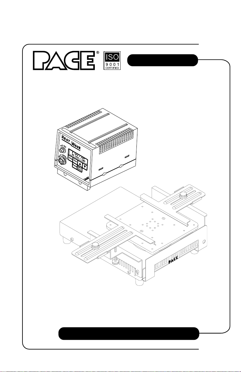
HS 200 System
HS 200 Heat Wave System
Operation & Maintenance Manual
Page 2

PACE Incorporated retains the right to make changes to specifications contained
herein at any time, without notice.
Contact your local authorized PACE Distributor or PACE Incorporated to obtain the
latest specifications.
The following are registered trademarks and/or servicemarks of PACE
Incorporated, Laurel Maryland U.S.A. and may only be used to identify genuine
PACE products or services:
AdapTip, Arm-Evac, Cir-Kit, ComForm I, ConducTweez, CRAFT,
Dual Path, Flo-D-Sodr, FuseSet, HandiPik, HotSpot, LapFlo, MBT,
Micro Portable, MicroChine, MiniChine, Mini-Wave, PACE, Pacenter,
Ped-A-V ac, PETS, Pik-Vac, PRC, Prep-Set, Pro-Evac, Redi-Rak, ResisT weez,
SensaTemp, Snap-Vac, Sodr-Pen, Sodr-X-Tractor, SR-3, SR-4, ST,
StripTweez, SwaPlater, ThermoBond, Thermo-Drive, ThermoJet, ThermoPart,
ThermoPik, ThermoT weez, Tip-Ev ac,Ventur-Evac VisiFilter .
The following are trademarks and/or servicemarks of PACE Incorporated, Laurel
Maryland U.S.A. and may only be used to identify genuine PACE products or
services:
Heat Wave, Pik-Tip, Pulse Plate, Sodrtek, ThermoFlo, Toolnet.
Since 1958, PACE Incorporated has provided
advanced technology training in all aspects of hand
soldering, rework and repair.
Additional copies of this manual or other PACE literature may be obtained from:
PACE Incorporated (301) 490 - 9860
Sales Administration (301) 498 - 3252 Fax
9893 Brewers Court
Laurel MD 20723-1990
Page 3

MANUAL NUMBER 5050-0406
REV. C
SYSTEM QUICK START
The HS 200 Heat Wave system is very easy to operate and can be
quickly set up for use in standard preheating operations. To begin
operation of your new system quickly, read the "Set-Up" and
"Quick Start Procedure" instructions detailed on pages 9-13
and page 18 of this manual. A shaded title bar on each of these
pages highlights their location.
For any questions regarding the following instructions, contact your local authorized
PACE dealer or contact PACE directly at:
Telephone (301) 490-9860, Fax (301) 604-8782
PACE Incorporated
9893 Brewers Court
Laurel MD 20723-1990
©1998 PACE Incorporated, Laurel MD. All rights reserved. Printed in the U.S.A.
1
Page 4

Table of Contents
TITLE PAGE
General Information ............................................................................................... 4
Introduction.................................................................................................. 4
Specifications ............................................................................................... 5
Parts Identification ....................................................................................... 6
Safety ...................................................................................................................... 8
Set-Up ..................................................................................................................... 9
System.......................................................................................................... 9
Hot Plate Installation .............................................................................. 9
Heat Shield Installation ........................................................................ 10
Board Holder Mounting ....................................................................... 10
Heater Unit/Power Source Connection................................................. 12
Air Hose Connection ............................................................................ 13
System Power Up ................................................................................. 13
Preheat Guidelines ................................................................................................ 14
Introduction................................................................................................ 14
Safe, Rapid Preheating............................................................................... 16
Preheat & Soak .......................................................................................... 17
Quick Start Procedure........................................................................................... 18
Operation .............................................................................................................. 19
Introduction................................................................................................ 19
Definitions.................................................................................................. 19
Overview.................................................................................................... 20
Factory Settings ......................................................................................... 22
Password .................................................................................................... 23
Board Set-Up ............................................................................................. 24
Power Up.................................................................................................... 25
Panel Controls ............................................................................................ 25
Manual Mode ....................................................................................... 26
Auto Mode............................................................................................ 27
Adjusting Set Temperature ................................................................... 28
Adjusting Time/Day of Week ............................................................... 29
Pump Operation.................................................................................... 30
Pik-Vac Operation ...................................................................................... 32
2
Page 5

Table of Contents
TITLE PAGE
Set-Up Mode......................................................................................................... 33
Introduction................................................................................................ 33
Operation ................................................................................................... 34
Entering Set-Up Mode.......................................................................... 34
Password ............................................................................................... 35
Time Protection .................................................................................... 35
Hot Plate Temperature Offset ............................................................... 36
Temperature Limits............................................................................... 36
Time Display ........................................................................................ 37
Auto Schedule ...................................................................................... 37
Auto Off................................................................................................ 39
Corrective Maintenance ........................................................................................ 40
Spare Parts ............................................................................................................ 41
Manual Improvement & Comment Form ............................................................. 42
TABLE PAGE
Table 1 Rapid Preheat Guidelines................................................................... 16
Table 2 Preheat & Soak Guidelines ................................................................ 17
Table 3 Factory Settings ................................................................................. 22
Table 4 HS 200 Checkout Procedures ............................................................ 40
Table 5 Spare Parts ......................................................................................... 41
3
Page 6

General Information
Introduction
Thank you for purchasing the PACE HS 200 Heat Wave system. This manual will
provide you with the information necessary to properly set up, operate and maintain
the HS 200 Heat Wave system.
The HS 200 is a fully integrated system which provides temperature controlled
bottom preheating of high mass electronic assemblies and components. Users can
select forced convective (forced air) or conductive (direct hot plate contact)
preheating.
The system utilizes the PPS 28 Heat Wave power source which incorporates
microprocessor control of system features as defined by the user (e.g., temperature
limits, password lock and scheduled operations). An integral motor pump supplies
forced air (air pressure) for convective applications and vacuum for component
handling operations using the PACE Pik-Vac handpiece.
NOTE
The PPS 28 Heat Wave power source is designed specifically for use with
the HS 200 Heat Wave system only. DO NOT use with any PACE
accessories other than the Heat Wave Heater Unit.
The Heat Wave heater unit has a wide area hot plate design which protects substrates
and components from thermal shock, minimizes board (PCB) warpage and allows
rapid solder reflow during rework applications.
4
Page 7

General Information
Specifications
The HS 200 Heat Wave system operates as a bottom preheater.
The system is available in either the 115 VAC or 230 VAC versions as listed below.
The 230 VAC version system bears the CE conformity marking which assures the
user that it conforms to all the requirements of council directive EMC 89/336/EEC.
System Power Requirements:
HS 200 - Operates on 97-127 VAC, 50/60Hz
Heater Unit - 300 Watts maximum at 115 VAC, 60Hz
PPS 28 Power Source - 7 Watts maximum at 115 VAC, 60Hz
HS 200E - Operates on 197-264 VAC, 50/60Hz
Heater Unit - 275 Watts maximum at 230 VAC, 50/60Hz
PPS 28E Power Source - 8 Watts maximum at 230 VAC, 50/60Hz
Temperature Range: 38°C to 371°C (100°F to 700°F)
Standard Hot Plate Dimensions: 140mm (5.5 inches) square
Board Holding Capacity:
Standard Board Holder: 20.3cm x 20.3cm (8" x 8")
Optional Board Holder: 45.7cm x 45.7cm (18" x 18")
EOS/ESD Specifications:
Hot Plate-To-Ground Resistance: Less than 2 ohms.
AC Leakage: Less than 2 millivolts RMS from 50Hz to 500Hz.
System Calibration:
No calibration steps are necessary to maintain the accuracy of the system.
5
Page 8
General Information
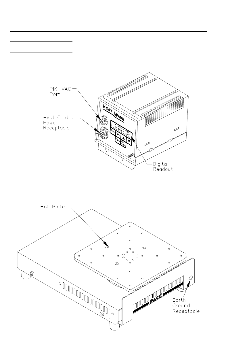
Parts Identification
PPS 28/E Heat Wave
Power Source
Heat Wave
Heater Unit
6
Page 9
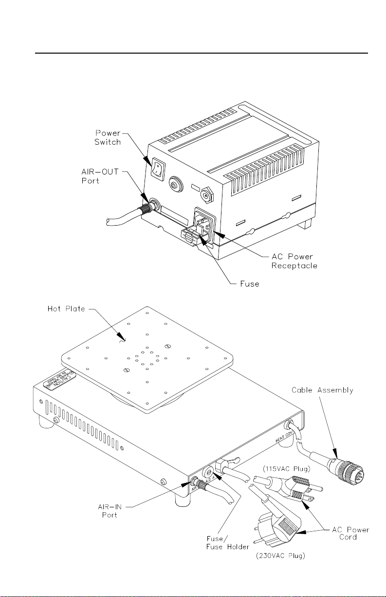
PPS 28/E Heat Wave
Power Source
General Information
Heat Wave
Heater Unit
(shown without
Heat Shield)
7
Page 10

Safety
The following are safety precautions which personnel must understand and follow
when using or servicing this product.
1. To prevent personnel injury, adhere to safety guidelines in accordance
with OSHA and other applicable safety standards.
2. Ensure that the Heat Shield is installed before the system is powered up.
Installation of the Heat Shield will help prevent accidental touching of
the Hot Plate. Severe burns may result if this shield is not installed.
3. The Hot Plate is hot when the system is powered on. Also, the Hot Plate
is hot for a period of time after the power is turned off. A "Warming UP"
message when the system is powered on or a "Cooling Down" message if
the Auto Scheduler powers the system down, may be displayed on the
Digital Readout alerting personnel that the Hot Plate is hot. Always treat
the Hot Plate as being hot. DO NOT touch the Hot Plate or areas
adjacent to the Hot Plate of the Heat Wave heater unit. Severe burns may
result.
4. Always use the system in the manner described in this manual. Use in
applications other than preheating can produce unacceptable results and
may cause damage to the system.
5. The PPS 28 Heat Wave power source is designed to power the Heat Wave
heater unit only.
6. Always use this system in a well ventilated area. A fume extraction
system such as those available from PACE are highly recommended to
help protect personnel from fumes.
7. The system should be used in a stable position on a work bench. Ensure
that the area below and immediately adjacent to the Hot Plate Heater Unit
is clear of flammable objects.
8. Exercise proper precautions when using materials (e.g., fluxes & solder
paste). Refer to the Material Safety Data Sheet (MSDS) supplied with
each material and follow all safety precautions recommended by the
manufacturer.
9. POTENTIAL SHOCK HAZARD - Repair procedures on this product
should be performed by Qualified Service Personnel only. Line voltage
parts will be exposed when the equipment is disassembled. Service
personnel must avoid contact with these parts when troubleshooting the
system.
8
Page 11
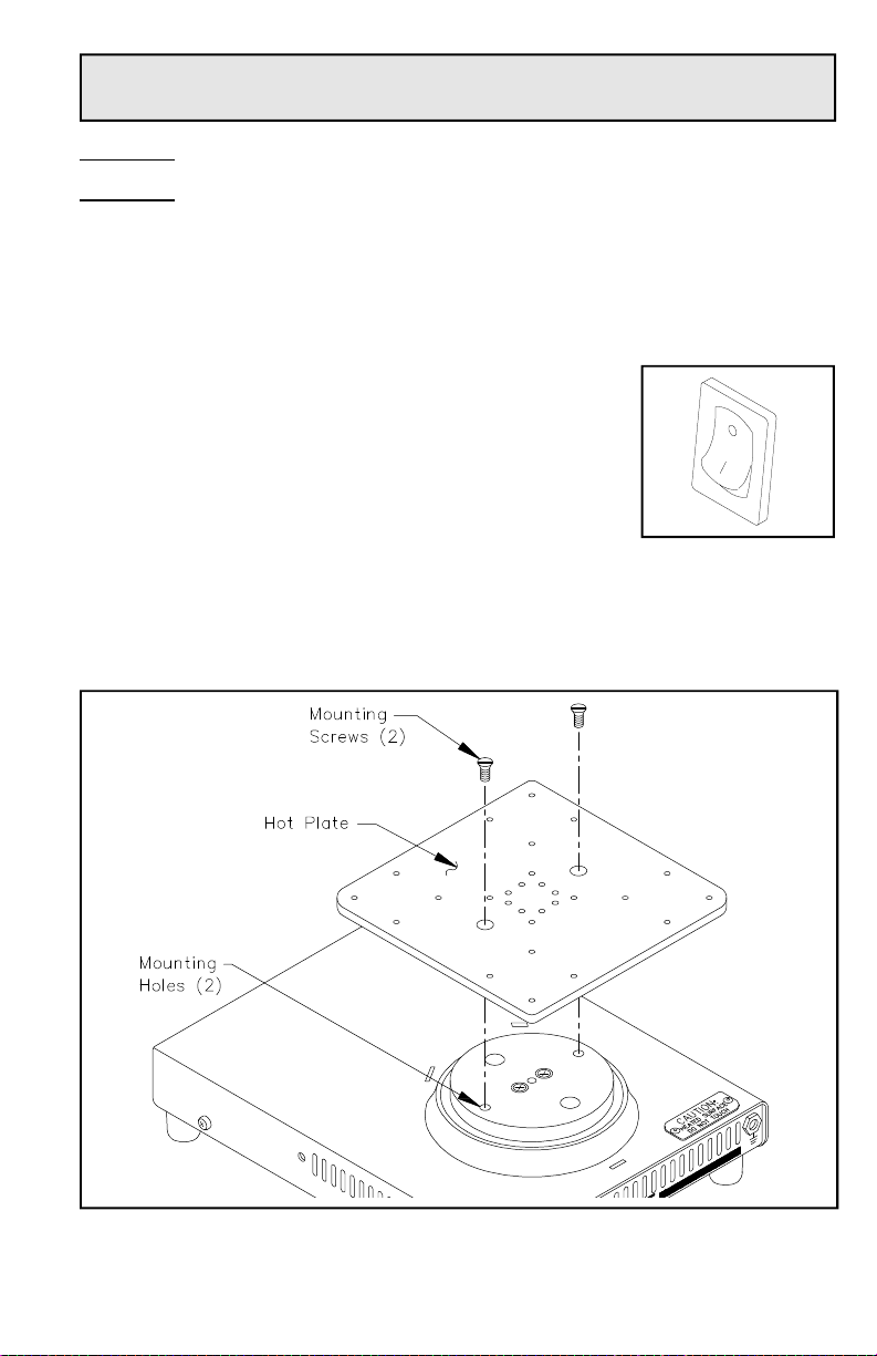
Set-Up
System
Set up the HS 200 Heat Wave system using the following steps and associated
drawings.
1. Store the shipping container(s) in a convenient location. These containers
can be reused to prevent damage if you store or ship the system.
2. Place the Power Switch (on rear of Heat Wave power
source) in the “OFF” or “0” position.
Hot Plate Installation
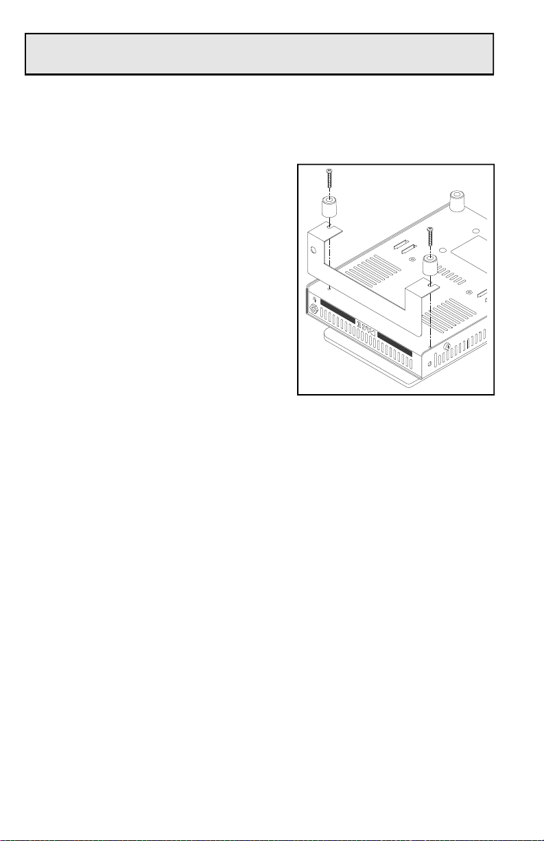
3. Place the Hot Plate in position on the Heat Wave heater unit with its 2
mounting holes in alignment with the 2 threaded Mounting Holes on the
heater assembly. Attach the Hot Plate to the heater assembly using the 2
enclosed Mounting Screws. Refer to illustration below.
4. Place the PPS 28 Heat Wave power source in position adjacent to the
heater unit.
9
Page 12
Set-Up
Heat Shield Installation
5. Install the Heat Shield onto the Heater Unit in the following manner:
a) Ensure that the Heater Unit is at
room temperature.
b) Place Heater Unit upside down (Hot
Plate down) on a suitable work
surface Position unit with the Earth
Ground Receptacle facing you.
c) Remove the 2 Mounting Scews
shown that secure the Rubber Feet to
the bottom, front of the Heater Unit.
DO NOT remove screws that secure
the remaining 2 Rubber Feet.
d) Place the Heat Shield in position as
shown between the 2 Rubber Feet
and the Heater Unit chassis.
e) Install the 2 Mounting Screws removed in step 5c to secure the
Rubber Feet and Heat Shield to the Heater Unit chassis.
Board Holder Mounting
The HS 200 Heat Wave system is supplied with a standard Board Holder which will
accomodate PCB sizes up to 20.3cm x 20.3cm (8" x 8"). An optional Board Holder
(part number 7900-0045) is available which accomodates PCB sizes up 45.7cm x
45.7cm (18" x 18").
6. If the optional Board Holder has been purchased, mount the holder to the
Heater Unit using the instructions included with the holder.
7. If you wish to use the standard Board Holder included with your system,
perform the following procedure. Use the illustrations as a guide.
a) Position the heater unit as shown.
b) Mount large bracket (item ➀) to the side of the heater unit using 2
mounting screws (item ➁).
10
Page 13
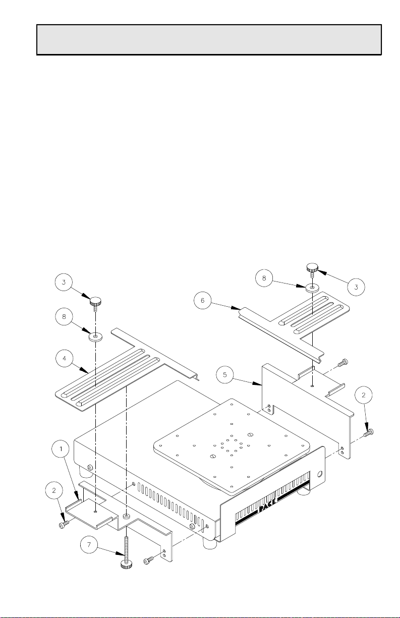
c) Place long holding clamp (item ➃) in position on bracket (item ➀).
Secure clamp in position using locking screw (item ➂) and flat
washer (item ➇).
d) Install leveling screw (item ➆). Adjust leveling screw until its end
just touches the bottom of the long holding clamp (item ➃).
e) Mount small bracket (item ➄) to the side of the heater unit using 2
mounting screws (item ➁).
f) Place short holding clamp (item ➅) in position on bracket (item ➄).
Secure clamp in position using locking screw (item ③) with flat
washer (item ➇).
Board Holder Assembly Parts Locator
Set-Up
11
Page 14
Set-Up
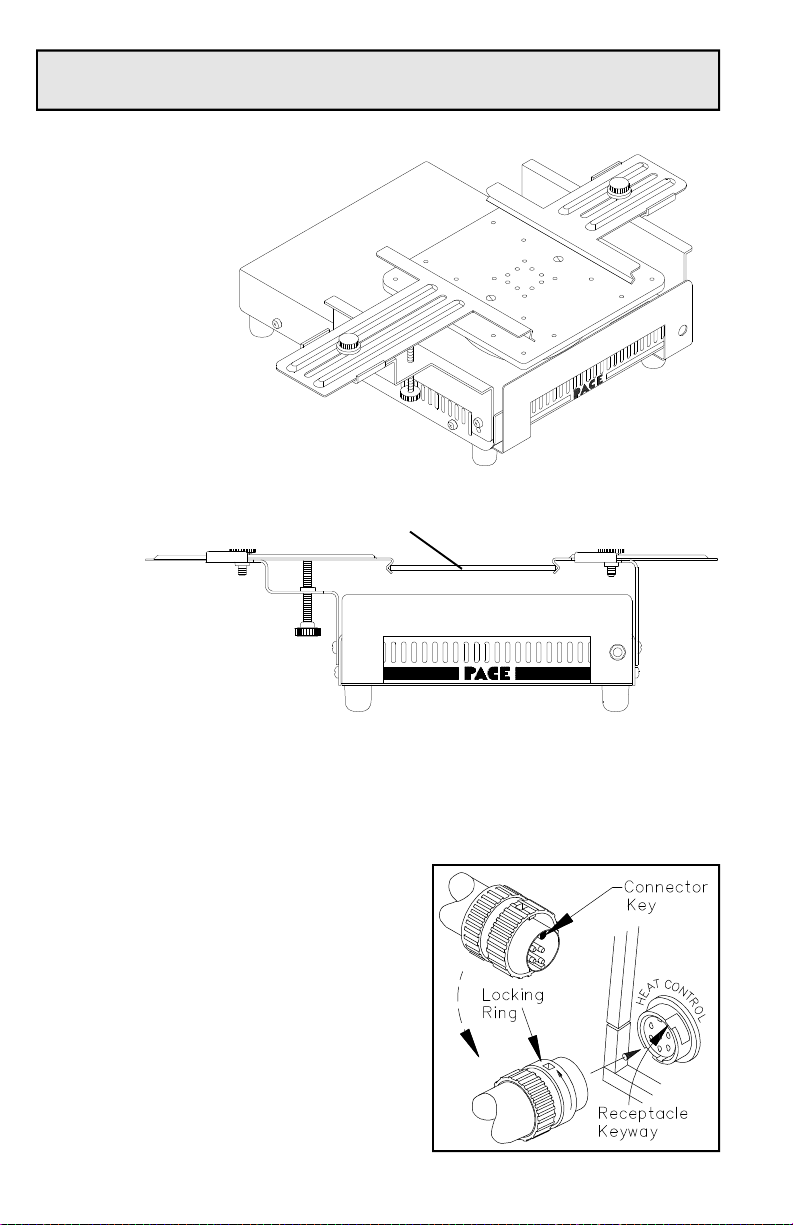
Assembled
Board Holder
Board Holder Assembly
With PCB Installed
PCB
Heater Unit/Power Source Connection
8. Connect the Heater Unit Cable Assembly connector plug to the HEAT
CONTROL Power Receptacle in the following manner:
a) With the Connector Key end facing
the power source, turn the Locking
Ring fully counterclockwise.
b) Align the Connector Key with the
Receptacle Keyway.
c) Insert the connector into the HEAT
CONTROL Power Receptacle.
d) Turn the Locking Ring fully
clockwise to secure in place.
12
Page 15

Set-Up
Air Hose Connection
Two air hoses (and fittings) are included with the system. One air hose provides air
pressure for convective preheating from the Heat Wave power source to the Heater
Unit. The second air hose provides vacuum to the Pik-Vac wand for component
handling.
9. Prepare 2 Air Hose assemblies by
installing a male quick disconnect hose
mount Fitting to each end of the supplied
air hoses. Insert the ribbed end of the
Fitting into the Air Hoses.
10. Connect one air hose assembly between the power source AIR OUT Port
and the AIR IN Port on the rear panel of the Heater Unit (see drawing on
page 7).
11. Connect the remaining air hose assembly between the PIK-VAC Port of
the power source and the PIK-VAC handpiece.
System Power Up
12. Insert the female end of the loose power cord into the AC Receptacle of
the Heat Wave power source.
13. Plug the prong ends of both the Heat Wave power source and the Heater
Unit into a 3 wire grounded AC supply receptacle. The system is now
ready for operation.
CAUTION
To insure operator safety, the AC supply receptacle must be checked for
proper grounding before initial operation.
14. Read the “Quick Start Procedure” section of this manual thoroughly
before operating the system.
13
Page 16

Preheat Guidelines
Introduction
The Heat Wave system provides process control to meet your specific requirements.
Follow these steps and use the following tables as a guideline to set the process
parameters for your particular applications:
1. Determine your basic board type:
a. Simple, Double Sided Board
b. SMT/Thru-Hole Board with approximately 6 or fewer internal layers
c. High Mass Board with approximately 7 or more internal layers
2. Determine your desired preheat temperature. The tables provide data for
commonly used preheat temperatures of 80 °C (176 °F), 100 °C (212 °F)
and 120 °C (248 °F).
3. To preheat quickly (yet always slower than 3 °C per second), see Table 1.
4. To preheat (always slower than 3 °C per second) and soak the board area
prior to reflow, see Table 2. Using this method:
a) the internal pump delivers hot air for quick ramp preheating.
b) when the pump stops, the radiant convection of the hot plate provides
a controlled soak at the desired preheat temperature.
NOTE
Thermal characteristics of every board assembly will be different. The
following tables provide a base starting point for the development of the
exact preheating parameters for your rework process.
When developing processes for removal/replacement of components, PACE
recommends the use of embedded thermocouples on the test board to
ensure optimum results.
14
Page 17

Preheat Guidelines
The following graph depicts a typical preheat and soak profile for a circuit board.
Setting the parameters in Table 1 will maximize the temperature ramp rate (3°C per
second or slower). Rework can then be performed immediately when the pump
turns off. The radiant heat from the hot plate will continue to slowly increase the
temperature of the workpiece.
Use the parameters in Table 2 to achieve a true ramp and soak temperature profile as
shown below. In this case, the radiant heat stabilizes the workpiece at the desired
preheat temperature.
15
Page 18

Preheat Guidelines
Safe, Rapid Preheating
To preheat quickly at safe ramp rates, set the following temperature and pump runtime parameters for the appropriate board type. These settings will quickly preheat
the repair area over the center of the Heat Wave plate to the desired temperature (yet
always slower than 3 °C per second). The entire board area over the Heat Wave plate
will also be preheated, but at a slightly slower rate.
This method allows the operator to quickly perform any necessary rework tasks. The
temperature on the board may continue to rise (at a slower rate) even after the pump
turns off.
Heat Wave
Desired
Preheat Temp.
Simple, Double Sided Board
Set
Temperature Pump Run-time
16
80°C
(176°F)
100°C
(212°F)
120°C
(248°F)
SMT/Thru-Hole Boards With Up To 6 Internal Layers
80°C
(176°F)
100°C
(212°F)
120°C
(248°F)
High Mass Board With 7 Or More Internal Layers
80°C
(176°F)
100°C
(212°F)
120°C
371°C
(700°F)
371°C
(700°F)
371°C
(700°F)
371°C
(700°F)
371°C
(700°F)
371°C
(700°F)
371°C
(700°F)
371°C
(700°F)
371°C
Table 1. Rapid Preheat Guidelines
28 seconds
36 seconds
54 seconds
44 seconds
64 seconds
112 seconds
56 seconds
114 seconds
190 seconds
Page 19

Preheat Guidelines
Preheat & Soak
The Heat Wave can be used to preheat and soak a circuit board before reflow takes
place. This helps to bake out the laminate and to equalize temperatures across the
repair area.
To preheat at a safe ramp rate, followed by a soak time (repair area of board
remaining within ±10 °C of desired preheat temperature), set the following
temperature and pump run-time parameters for the appropriate board type.
This method provides quick ramp preheating. When the pump stops, the radiant
convection of the hot plate provides a controlled soak at the desired preheat
temperature. This prevents the board from heating more than 10°C over the desired
temperature.
Heat Wave
Desired
Preheat Temp.
Simple, Double Sided Board
80°C
(176°F)
100°C
(212°F)
120°C
(248°F)
SMT/Thru-Hole Boards With Up To 6 Internal Layers
80°C
(176°F)
100°C
(212°F)
120°C
(248°F)
High Mass Board With 7 Or More Internal Layers
80°C
(176°F)
100°C
(212°F)
120°C
Set
Temperature Pump Run-time
250°C
(482°F)
300°C
(572°F)
320°C
(608°F)
250°C
(482°F)
300°C
(572°F)
340°C
(644°F)
250°C
(482°F)
300°C
(572°F)
360°C
50 seconds
56 seconds
72 seconds
114 seconds
130 seconds
180 seconds
208 seconds
212 seconds
Table 2. Preheat & Soak Guidelines
17
Page 20

Quick Start Procedure
The following procedure assumes that the Heater Unit Hot Plate is at room
temperature and the power source is in the Manual Mode with no installed Password
(as received from factory). If not, displayed messages may be different.
1. Set-Up - Ensure that the Set-Up procedure has been performed. Check the
following:
a) Heater Unit connection to the Heat Wave power source.
b) Power cord connections (2) between the house AC supply and both
the Heater Unit & power source.
c) Ensure that the system is properly mounted (on standard Board
Holder or on large Board Holder).
2. Air Hose Connection - If you wish to use the Convective (forced air)
method of preheating, connect the Air Hose Assembly between the power
source AIR OUT Port and the Heater Unit AIR IN Port (see illustrations
on page 21).
3. Apply Power - Turn the Power Switch (on power source) to the “ON”
(“1”) position. The Digital Readout will display "Heat Wave" and then a
Version number for 2 seconds each. Then, a "Warming Up" message
(with a countdown time) or "System is OFF" message will be displayed.
4. Adjust Temperature - Press and release the TEMP Key. Press and
release the Scroll UP (▲) Key to increase or the Scroll Down (▼) Key to
decrease the desired temperature. Press and release the TEMP Key. The
Digital Readout will now display the "Warming Up" and time out
message. When the system times out, the Digital Readout will display
the actual Hot Plate temperature. Allow time for the temperature to
stabilize at the set temperature.
5. Install PCB for Repair - Place the PCB to be repaired in the Board
Holder. Position PCB repair area directly over the center of the Hot
Plate. When repairing large PCBs, you may wish to install the optional
PCB Supports supplied in kit P/N 6993-0197-P1.
6. Actuate Motor Pump - Optional Step - Press and release Pump Key to
apply convective flow of hot air to PCB repair area. Press and hold the
Pump Key for 2 seconds, then release to allow adjustment of the pump
run time.
IMPORTANT
PACE recommends that you not read the “Set-Up Mode” section until after
you feel comfortable with manual operation of the system. Please read the
“Operation” section thoroughly before changing any system settings.
18
Page 21

Operation
Introduction
The HS 200 Heat Wave system is very easy to operate. As received from the
factory, the system can be quickly set up for use in standard preheating operations.
Simply perform the Quick Start Procedure (page 14) to begin system operation.
For operations requiring user defined controls, use this portion of the manual.
Definitions
Auto Mode - Mode in which the system will turn on and off for periods of
operation as determined by the user-defined Auto Schedule settings in system
memory.
Auto Off - Safety feature which turns power off after 12 hours of continuous use in
the Manual Mode. This feature is enabled or disabled in the Set-Up Mode.
Auto Schedule - Feature which enables the operator (when in Set-Up Mode) to
program the system to turn on for a specific time period when in the Auto Mode.
The operator can select enable or disable for any day(s) of the week .
Conductive Preheating - Preheating a board (PCB) by transferring heat directly
from the hot plate to the board.
Convective Preheating - Preheating a board (PCB) by transferring heat using
forced air through the hot plate and onto the board. With convective preheating
there is no direct contact between the hot plate and the board.
Manual Mode - Mode in which the system is turned on and off as determined
by the operator.
Operating Temperature - The true temperature at which the hot plate operates
at any given time. This temperature is displayed on the Digital Readout (“Temp
= XXX”) in normal operation (Temperature Display Mode).
Password - Feature which, when enabled, will prevent unauthorized alteration
of stored system parameters and feature settings.
Set Temperature - The operator selected idle hot plate temperature (“Set Temp
= XXX”) entered into the system memory.
Set-Up Mode - Mode of operation in which the operator can quickly and easily
adjust the system parameters (e.g., temperature limits, password, auto schedule).
Temperature Display Mode (normal operation) - Normal operating mode of
the system in which the actual hot plate temperature is displayed.
Time Protected - System requires that the Password stored in system memory
be entered before the current time setting can be altered.
Time Unprotected - Current time setting can be changed without Password entry.
19
Page 22

Operation
Overview
The following is a brief summary of basic system operational functions.
1. Temp Key - Press and release to set a desired Hot Plate temperature using
the Scroll keys to adjust. Also used in Set-Up Mode.
2. Time Key - Press and release to display time of day and to select time
(hours or minutes) for change.
3. Scroll Up (▲) Key - Press and release to increase Set Temperature, Time
or Day of Week settings.
4. Scroll Down (▼) Key - Press and release to decrease Set Temperature
and time settings.
5. Pump Key - Press and release to turn pump on or off for Convective
Heating operations and for component handling operations using the PikVac handpiece. Pump run time is adjustable from 10 seconds minimum
to 1 hour maximum or for continuous operation. As received from the
factory, the pump will run continuously when the key is pressed.
6. Man/Auto Key - Toggles system between Auto and Manual Modes.
7. Digital Readout - Provides a 2 line LCD display of system information.
The Digital Readout will display:
a) ”Heat Wave” for 2 seconds on initial power up.
b) The software version of the Heat Wave power source for 2 seconds.
c) A “Warming Up” or a “Cooling Down” message plus the Set
Temperature and estimated time (in minutes and seconds) to reach Set
Temperature.
d) An “On” & "Off" time message for 5 seconds and then "Set
Schedule" if the system is in Auto Mode with no Set Schedule.
e) Temperature in °C or °F (programmable in Set-Up Mode).
f) The Operating Temperature when it stabilizes. The system is now in
Temperature Display Mode (normal operation).
20
Page 23

Operation
g) An hour glass graphic to indicate that the 12 hour timer is active and
the system will automatically power down if used for 12 continuous
hours of manual operation.
h) A variety of text messages to denote system status (e.g., “Open Sensor
Check Heater” if the Heater Unit Cable Assembly is not connected to
power source).
8. AIR OUT Port - Connect the air hose assembly between this port and the
AIR IN Port of the Heater Unit to supply forced air when utilizing
Convective Heating. Pump must be turned on when preheating in this
manner.
9. AIR-IN Port - See AIR OUT Port above.
10. PIK-VAC Port - Connect the air hose assembly between this port and the
Pik-Vac handpiece. Used to pick and place components.
21
Page 24

Operation
Factory Settings
The HS 200 Heat Wave system comes equipped with a number of features which
may be adjusted, enabled or disabled as desired by the user. Listed below are the
features and factory settings of each. To change and/or learn about any of these
features, refer to the applicable part of the "Operation" or "Set-Up Mode" portions of
this manual.
FEATURE FACTORY SETTING
Password No Stored Password
Hot Plate Size 140mm (5.5 inch) square
Temperature Scale (°C/°F) °F
"Lo" (lower) Temperature Limit 38°C (100°F)
"Hi" (upper) Temperature Limit 371°C (700°F)
Clock Format 12 Hour
Auto Scheduler
Auto Off Disabled
Pump Run Time Continuous Operation
Time To Auto Off (manual mode, continuous
operation)
Time Protection Disabled
Set Temperature (of Hot Plate) "OFF"
All Days & Times
Disabled
12 Hours, Not Adjustable
Table 3. Factory Settings
22
Page 25

Operation
Password
The Password feature of the HS 200 Heat Wave system, when activated, will prevent
unauthorized alteration of stored system parameters and feature settings. If a
Password has been installed, the Digital Readout will display an instruction to enter
a Password (a 4 key sequence of the keys on the front panel of the power source)
when a setting change is attempted or when entering the Set-Up mode.
Entry of the correct Password at this point will allow the operator to proceed with
the desired changes. The Password protection will be reactivated if the system is
turned off and then back on. Refer to the “Set-Up Mode” section of this manual for
instructions on entering, changing or removing a Password.
23
Page 26

Operation
Board Set-Up
A PC Board can be may be placed or clamped in position on the Heater Unit
utilizing the standard or optional Board Holder accessory. When working with large
PCBs, you may wish to install the PCB Supports supplied in kit part number 69930197-P1.
Standard Board Holder Mounting
(see pages 10-11 for details)
Optional Board Holder Mounting
(See instructions with Optional Board Holder for details)
24
PCB Support
(See instructions with PCB Support Kit for details)
Page 27

Operation
The following instructions assume that the Heater Unit Hot Plate is at room
temperature and the power source is in the Manual Mode with no installed Password.
If not, displayed messages may be different.
Power Up
1. Turn the Power Switch ON (“1”).
Panel Controls
2. The Digital Readout will now display “Heat Wave” for 2 seconds and
then the microprocessor revision for 2 seconds.
NOTE
If the HEAT CONTROL Power Receptacle does not have the Cable Assembly
connector plug (from Hot Plate) attached, “Open Sensor Check Heater” will be
displayed on the Digital Readout.
3. The system has 2 modes of operation: Manual and Auto. The system will
power up to the same mode as when power was last turned off. The
display on the Digital Readout is determined by the following:
a) With the system in the Manual Mode, or in Auto Mode with a set
schedule, a “Warming Up ... Set Temp” message will be displayed.
Allow time for the Hot Plate to reach the Set Temperature.
NOTE
The system is shipped from the factory to enter Manual Mode and will
display a "System is OFF" message on initial power up. A “Set Schedule”
message will be displayed if in Auto Mode & the Auto Schedule is disabled.
To enable the Auto Schedule, refer to the Set-Up Mode section of this
manual.
b) An “OFF” or “ON” time or a "Warming ... Set Temp" message will be
displayed if the system is in the Auto Mode and a schedule has been
stored in system memory.
c) If the system is in the Auto Mode but no schedule is enabled, the
current time and a “Set Schedule” message will be displayed. No
power is being applied to the Hot Plate.
25
Page 28

Operation
Manual Mode
4. If the system is displaying an “ON”, “OFF” or "Set Schedule" message
(Auto Mode), press the Man/Auto Key to change to Manual Mode.
NOTE
If a "System is OFF" message is displayed, press and release the Temp Key
& use Scroll keys to adjust desired Hot Plate temperature. Press and release
the Temp Key or wait 5 seconds; turn Power Switch OFF ("0") then back ON
("1"). The "Warming Up" message will now be displayed.
5. Notice in the upper right corner of the
“Warming Up” display is a timer clock.
This clock is displaying the estimated
time remaining to reach Set Temperature
in minutes and seconds. The bottom
line displays the Set Temperature.
6. When the temperature of the Hot Plate
nears the Set Temperature, the actual
temperature will be displayed. The
displayed temperature will increase to a
point higher than the Set Temperature.
This is NORMAL. Observe the Digital
Readout as the displayed temperature
decreases and settles in at the Set
Temperature.
26
Page 29

Operation
7. The system will now maintain the Set Temperature unless one of the
following occurs:
a) If the Auto Off feature is enabled, the system will turn off after 12
hours of continuous operation.
b) If the Set Temperature is lowered, the temperature will decrease to the
new setting.
c) If the system Power Switch is turned off.
Auto Mode
In the Auto Mode, the system will turn On and Off at predetermined times entered in
the Set-Up Mode. The Auto Schedule portion of the Set-Up Mode routine allows the
operator to set a time for system power up and power down. This selected time
period is then enabled or disabled for each individual day of the week. For example,
a power on time period of 8 am to 5 pm can be enabled for Monday through Friday
but the system will remain off (disabled) Saturday and Sunday.
8. Press and release the Man/Auto Key.
The system is now in the Auto Mode. A
time "On = ... Off = ..." message will be
displayed for 5 seconds.
9. The Digital Readout will now display
the actual temperature (Temperature
Display Mode) plus one of the
following:
a) The time the system will turn off (if
in a scheduled On period).
b) The time the system will turn On (if
in a scheduled Off period) if any day
has been enabled.
c) If all days are disabled, a "Set
Schedule" message will be displayed.
27
Page 30

Operation
Adjusting Set Temperature
10. Press and release the Temp Key. The
Set Temperature is now displayed on the
Digital Readout. If no other Key is
pressed within 5 seconds, the system
will revert to the Temperature Display
Mode (normal operation). Allow time
for the system to change back.
11. Press and release the Temp Key, then, immediately press and hold the
Scroll Up (s) Key. Observe the display as the Set Temperature increases
first in increments of 1° and then in increments of 10°. Release the key.
12. Press and hold the Scroll Down (t) key. Observe the display as the Set
Temperature decreases first in increments of 1° and then in increments of
10°. Release the key; press and release the Temp Key (or wait 5 seconds).
NOTE
The Set Temperature can only be within the set temperature limits. If a limit
(upper or lower) is reached, the lower limit would display “Off”; the upper limit
would not allow the Set Temperature to exceed that limit. Temperature limits
can be adjusted in the Set-Up Mode.
28
Page 31

Operation
Adjusting Time/Day of Week
13. Press and release the Time Key. If the
system is Time Protected, the Digital
Readout will display a request to enter the
Password before altering the time setting;
enter the Password. The current time will
now be displayed along with a bottom
line display. If no other Key is pressed
within 5 seconds, the system will revert to
the Temperature Display Mode (normal
operation). Allow time for the system to
change back.
NOTE
The time will be displayed in either a 12 hour or 24 hour format as determined
in the Set-Up Mode. Also, throughout the Time setting process (steps 14-
19), a 5 second timeout between any key actuations will cause the system
to revert to Temperature Display Mode (Normal Operation).
14. Press and release the Time Key twice; the hour portion of the time will
start to flash.
15. Use the Scroll Up (s) and Scroll Down (t) Keys to change the hour.
Ensure that the displayed hour is correct before continuing.
16. Press and release the Time Key again. The tens digit of the minutes
display will begin to flash. Use the Scroll Up (s) and Scroll Down (t)
Keys to change the minutes display in increments of 10. Ensure that the
displayed minutes is correct before continuing.
17. Press and release the Time Key again. The single (ones) digit of the
minutes display will begin to flash. Use the Scroll Up (s) and Scroll
Down (t) Keys to change the minutes display in increments of 1.
Ensure that the displayed time is correct before continuing.
29
Page 32

Operation
18. Press and release the Temp Key. The day of the week is now displayed.
Immediately press and release the Scroll Up (s) Key several times and
watch as the day changes. Ensure that the displayed day is correct before
continuing.
19. Press and release the Temp Key again or allow the system to time out
(after 5 seconds) and revert to normal operation.
NOTE
Any changes to the time or day of the week are stored in system memory
when exiting the Set-Up Mode and the system changes back to Normal
Operation (Temperature Display Mode).
Pump Operation
20. The power source has an integral motor pump which provides forced air
for Convective Heating and vacuum for component handling operations.
NOTE
The motor pump is not designed for other operations such as solder
extraction. DO NOT use the motor pump for any applications other than
those described in this manual.
To activate the pump, press and release
the Pump Key. Press and release the
key again to terminate pump operation.
30
Page 33

Operation
The Pump run time is adjustable from 10 seconds minimum to 1 hour maximum or
for continuous operation. As received from the factory, the pump will run
continuously when the key is pressed.
21. Press and hold the Pump Key for 2
seconds. The digital Readout will now
display current Pump run time as
"Cont." (Continuous) or in hours,
minutes, and seconds.
22. Press and release the Time Key.
23. Press and release the Scroll Down (t) and Scroll Up (s) Keys several
times. Notice the Pump run time change from Continuous to 1 (hour) to
0 hours. When 0 hours is displayed the minimum time displayed will be
10 seconds.
24. If the Pump run time is "Cont.", press and release the Scroll Down (t)
Key.
25. Press and release the Time Key several times. Notice the display
changes with each press and release of the Key. The hour digit will flash,
then the minutes times 10 digit, then the minutes digit, then the seconds
times 10 digit, then the seconds digit. When the digit is flashing, that
time segment is subject to change by use of the Scroll Keys (s & t).
26. Adjust the Pump run time to 1 minute (as an example) using the Time
Key plus the Scroll Up and Scroll Down Keys.
27. Press and release the Temp Key to return to normal operation.
28. Press and release the Pump Key. The
Pump is now activated. Observe the
displayed Pump run time as the timer
counts down to 0. Upon reaching zero,
the pump will turn off. Also, the pump
will turn off immediately if the Pump
Key is pressed a second time when the
pump is operating.
29. Adjust the Pump run time to the time desired for your application using
steps 21 thru 28 as a guide.
31
Page 34

Operation
Pik-Vac Operation
1. Connect the Pik-Vac air hose assembly between the
PIK-VAC Port and the back of the Pik-Vac
handpiece.
2. Install the metal tip and desired Vacuum Cup onto
the end of the handpiece.
3. Turn the Power Switch (on rear of power source)
ON (“1”).
4. Press and release the Pump Key to activate vacuum flow.
NOTE
The Pump run time should be set for continuous operation when using the
Pik-Vac handpiece.
5. Grasp the handpiece as you would a pencil with the Vacuum Cup
pointing down and the Vacuum Control Port pointing up.
6. Place the Vacuum Cup gently on the top surface of the component body.
Caution must be taken to avoid bending of leads on fine pitch devices.
7. Place one finger over the Vacuum Control Port. Vacuum is now being
applied to the component body.
8. Gently lift the component from its position.
32
Page 35

Set-Up Mode
9. Lower the component in position (illustration depicts placement of
component on land pattern).
10. Slide the finger from the Vacuum Control Port to release the component.
11. Press and release the Pump Key to stop vacuum flow.
Introduction
The menu driven Digital Readout of the HS 200 Heat Wave system in the Set-Up Mode
allows you to easily customize your system. In most cases, the operator is directed as to
which key(s) to press in order to proceed. In cases where specific instructions are not
displayed, simply press and release the Temp Key to proceed to the next step.
No calibration steps are necessary to maintain the accuracy of the system.
In Set-Up Mode, you can:
1. Enter, remove, or change a Password.
2. Select Hot Plate standard size or enter temperature offset constant for
custom size in use on Heater Unit.
3. Set the Default Temperature scale to °C or °F as desired.
4. Change the Upper and Lower Temperature limits of the Hot Plate.
5. Select a 12 hour or 24 hour time clock.
6. Program Auto Schedule for power on/off period and enable or disable for
each day of the week.
7. Enable or disable the Auto Off feature.
33
Page 36

Set-Up Mode
Operation
Entering Set-Up Mode
1. Place the Heat Wave Power Switch in the OFF (“0”) position.
2. Press and hold the Temp and Scroll
Down (▼) Keys together.
3. Place the Power Switch in the ON
(“1”) position. The Digital Readout
will display “HeatWave”, change to
read “Version XXXX” and the
change again to read “Password
Needed?”
4. Release the Temp and Scroll Down
(▼) Keys. The system is now in the
Set-Up Mode. “Enter Password"
will be displayed if a Password is
currently stored in system memory.
34
Page 37

Set-Up Mode
Password
5. If a Password has been previously stored in system memory, enter the 4
key sequence Password; an asterisk (✶) will be added to the display as
each key is actuated.
NOTE
If an incorrect Password sequence is entered, the system will immediately
revert to normal operation.
6. At this point the Digital Readout will ask you:
a) If you would like to retain the “Same” Password (if previously stored)
in the system. If you do, press the Temp Key (directly beneath
“Same”).
b) If you do not wish to have a Password stored in the system, press the
Time Key (directly beneath “No”). Any previously stored Password
will be removed from the system.
c) If you wish to enter a new Password, press the Scroll Up (▲) Key
(directly beneath “Yes”). The Digital Readout will now display
“Enter New Password”. Enter a new 4 key sequence Password. As
each key is pressed, an asterisk (✶) will be displayed. Once the fourth
key is pressed, a “Time Protected” or “Time Unprotected” message
will be displayed if the system has a Password stored in memory.
Time Protection
7. If a “Time Protected” or “Time
Unprotected” message is displayed
(Password stored in system memory), the
Scroll Up (▲) Key can be pressed to toggle
between the two messages. If you wish to
require the operator to enter the stored
Password before altering the time setting in
normal operation, the “Time Protected”
message should be displayed. Press and
release the Temp Key to continue.
The message displayed in this illustration,
indicates that the system clock can not be
changed without entering the password.
35
Page 38

Set-Up Mode
Hot Plate Temperature Offset
8. A “Select Plate” message will be
displayed. The standard Hot Plate size is
140mm (5.5”) square; this is the default
size. The system has a permanently
stored temperature offset constant which
automatically compensates for
temperature losses between the
temperature sensor and the Hot Plate.
This ensures that the plate temperature
matches the set temperature. If your
system has a different Hot Plate, actuate
the Scroll Down (t) Key. Then, use the
scroll keys to adjust the temperature
offset for your Hot Plate.
NOTE
The Digital Readout will display the standard Hot Plate size as 140mm if
temperature is being displayed in °C or as 5.5" when temperature is
displayed in °F.
Temperature Limits
9. Press and release the Temp Key. The
Digital Readout will now display
whether temperature will be shown in
°C or °F. Press and release the Scroll Up
(s) Key to change.
10. Press and release the Temp Key. The
Low (“Lo”) Temperature Limit setting is
now displayed. Use the Scroll keys to
adjust.
36
Page 39

11. Press and release the Temp Key. The
High (“Hi”) Temperature Limit setting is
now displayed. Use the Scroll keys to
adjust.
Time Display
12. Press and release the Temp Key. The
Time Mode setting is now displayed.
With a “12Hr” setting, the displayed
time will be the same as on a digital
clock (with AM and PM suffixes). A
“24Hr” setting will display 24 hour
(military) time. Use the Scroll Up (s)
Key to change the displayed time mode.
Set-Up Mode
Auto Schedule
13. Press and release the Temp Key. The
displayed message will now ask if you
wish to change the Auto Schedule. If
you wish to change settings, press and
release the Temp Key. If you do not
wish to change Auto Schedule, press and
release the Time Key; proceed directly
to step 18.
37
Page 40

Set-Up Mode
14. The stored turn on time is now
displayed. Find the horizontal line
beneath a digit of the displayed time.
Use the Time Key to change the selected
digit & the Scroll Keys to change the
value of the selected digit.
15. Press and release the Temp Key. The
stored turn off time is now displayed.
Find the horizontal line beneath a digit
of the displayed time. Use the Time
Key to change the selected digit & the
Scroll Keys to change the value of the
selected digit.
16. Press and release the Temp Key. A day
of the week message is displayed with
“is Disabled” or “is Enabled”. Press and
release the Scroll Up (s) Key to change.
If “is Enabled” is displayed, the on and
off schedule will activate the system on
that day for the specified time period
when the system is used in the Auto
Mode.
17. Press and release the Temp Key. The next day of the week will be now
be displayed. Perform steps 16 & 17 until all 7 days have been set.
38
Page 41

Auto Off
18. An Auto Off message will now be
displayed with “Disabled” or “Enabled”.
If “is Enabled” is displayed, the system
when in the Manual Mode of operation,
will remove power from the system if it
is operated for 12 continuous hours. An
hour glass graphic will also be displayed
in the upper left corner of the digital
readout (in normal operation) to indicate
that the 12 hour timer is active.
19. Press and release the Temp Key. An
“Exit Setup?” message will now be
displayed. Press and Release the Temp
Key to exit or press and release the Time
Key to restart the Set-Up Mode
sequence.
Set-Up Mode
20. When the Temp Key is actuated to exit setup, the system will revert to
normal operation and in the mode (Manual or Auto) in which the system
was last used. Any setting changes are now stored in system memory.
39
Page 42

Corrective Maintenance
Use the following Checkout Procedures (Table 4) to determine the source of a
malfunction.
Symptom
No Digital Readout;
no motor pump on
Heat Wave Power
Source. No heat to
Hot Plate.
No heat to Hot Plate.
Digital Readout on
power source
functions normally.
No heat to Hot Plate.
Digital Readout on
power source
displays "Open
Sensor Check
Heater".
No Ground
Probable
Cause
Power Switch
in "0" (Off)
position.
Blown Fuse in
power source.
Blown Fuse in
Heater Unit.
Open Heater. Contact the PACE
Heater Unit
Cable
Assembly not
connected to
Heat Wave
power source.
Open Heater
Sensor.
Oxidation on
Checkout
Procedure Solution
Check for blown
fuse in AC
Receptacle of Heat
Wave power
source.
Check Fuse in Fuse
Holder on rear of
Heater Unit.
Service Department.
Check connection
to HEAT CONTROL
Power Receptacle.
Contact the PACE
Service Department.
Check resistance -
Turn Power
Switch to "1"
(On) position.
Replace fuse
in AC
Receptacle
and recheck
system.
Replace Fuse
and recheck
system.
Replace
Heater
Assembly in
Heater Unit.
Connect Cable
Assembly
connector
plug to Heat
Wave power
source.
Replace
Heater
Assembly in
Heater Unit.
Clean Heater
Table 4. HS 200 Checkout Procedures
40
Page 43

Spare Parts
Listed below are the HS 200 system spare parts which may be ordered through your
local authorized PACE distributor. To obtain any HS 200 parts other than those
listed below, contact the PACE Service Department at Tel. #1-888-535-7223 (tollfree), Fax #(301) 483-7030.
Ite
# Description
1 Hot Plate, 140mm (5.5 inch) inches square 1335-0177
2 Detachable Power Cord for 115VAC systems 1332-0094
Detachable Power Cord for 230VAC systems 1332-0093
3 Pik-Vac Handpiece 7027-0001-P
4 Vacuum Cup Kit 6993-0154
5 PACE Screwdriver 1100-0230
6 Large Board Holder Kit (optional accessory) 7900-0045
7 PCB Support Kit 6993-0197
Part
Number
Table 5. Spare Parts
CAUTION
POTENTIAL SHOCK HAZARD - Disassembly of power source or heater
unit exposes line voltage parts. Replacement of heater unit power cord or
any internal parts must be performed by qualified service personnel only.
Contact the PACE Service Department for assistance.
41
Page 44

MANUAL IMPROVEMENT & COMMENT FORM
Instructions
1.
Duplicate this form and submit comments on the copy. Keep the original to make
future comments.
2.
Complete all requested information.
3.
Submit completed form to:
PACE Incorporated
Applications Engineering Fax: (301) 604-8782
9893 Brewers Court
Laurel, MD 20723-1990 U.S.A.
Document #
Nature of Change (Identify page and paragraph and include proposed rewrite, if
possible.)
Reason for Recommendation
5050-0406 Rev. C
Date of Submission:
Name of Submitter: Company or Organization:
Mailing Address: Telephone: ( )
Voice:
Fax:
e-Mail:
Thank you for your comments; they are greatly appreciated!
42
 Loading...