

Page 1
HS 100 Pre-Heater Operations Manual (P/N 5050-500)
1. Packing Contents (8007-0358-P1 or 8007-0359-P1)
a. HS 100 System (1 each)
b. External PCB Supports
c. Power Cord (1 each)
2. Specification
Voltage
8007-0358-P1
8007-0359-P1
120 VAC
230 VAC
Heater Ceramic, 80 W
Temperature Range
Approx.130 - 190
Temp. Adjustment Zero point switching 50-100%
Dimension 142mm (5.6”) W x 50 (2”) mm H x
80mm (3.2”) D
Weight 500 g (1.1 pounds)
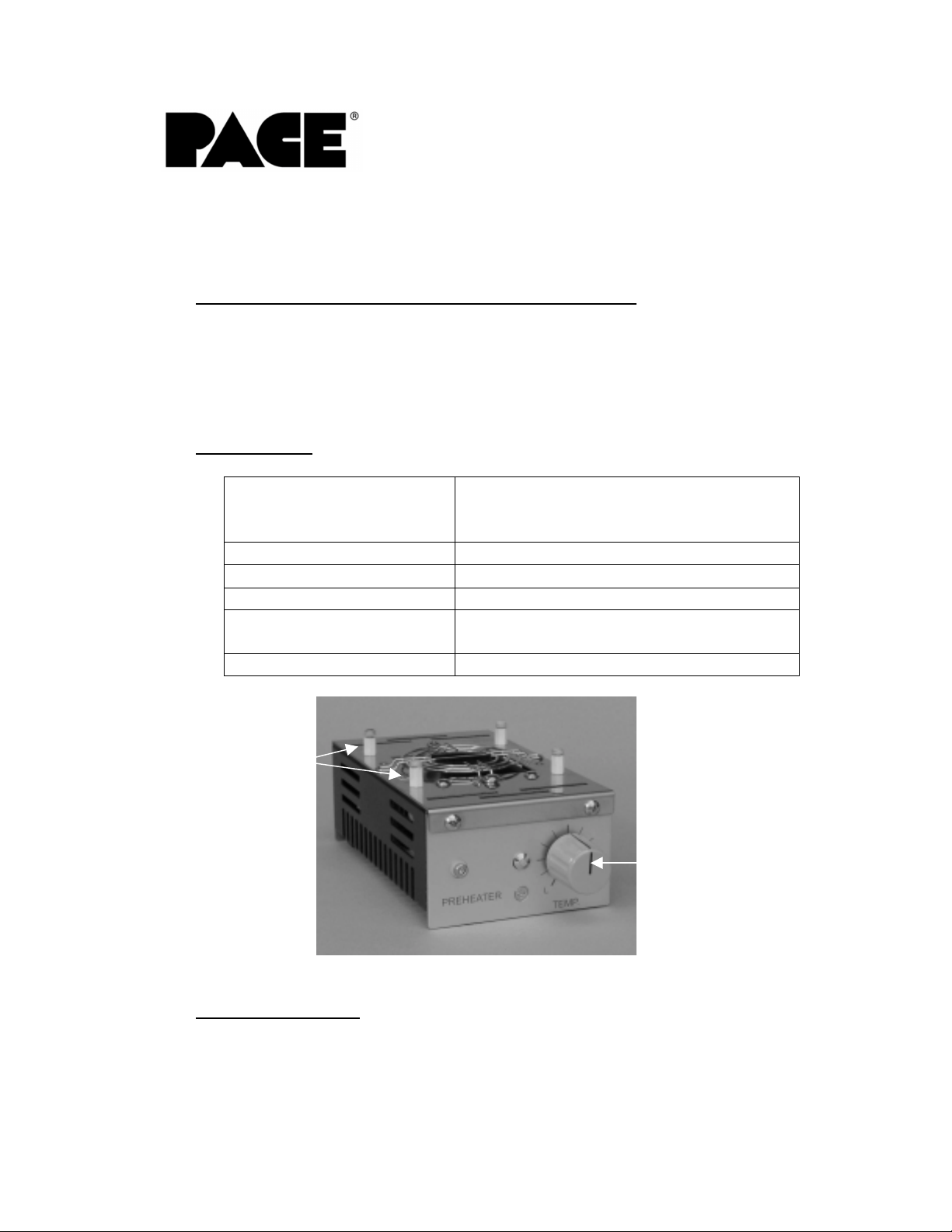
PCB Supports
3. Safety Information
a. Do not contact the Heater or its peripheral parts during operation.
b. Once turned off, let the unit cool completely before contacting.
Temperature
Control Knob
Page 2

c. When using Fluxes, use fume extractio n equipment or use in a well
ventilated area to minimize operator exposure to fumes.
4. Features
a. The HS 100 can be used to provide pre-heating to small PCBs or
to provide localized pre-heating capability on larger PCBs.
b. The HS 100 is ideal for using in conjunction with desoldering and
convective systems. Using the HS 100 in conjunction with other
types of equipment allows for lower temperatures to be used and
for shorter cycle times.
5. Set-Up
a. Place HS 100 on a stable work surface.
b. Connect Power cord, to the main body.
6. Operation
a. Turn on the power switch on the back of the HS 100.
b. Set the temperature control knob to the desired setting.
c. Allow the unit to warm up for 2 or 3 minutes after turning the unit
on.
d. Place PCB on PCB supports, External supports maybe used as
required.
e. A thermo-couple is recommended for PCB temperature verification.
17. Maintenance
The maintenance should only be completed by qualified personnel
designated by your company.
18. Regulation
The system is in conformity with the Low Voltage Directive and EMC
Directive 73/23 EEC as last amended by EEC Directive 93/68/EEC.
19. Service
Please contact PACE or your local distributor for service and repair.
HS 100 Operations Manual, Rev A
www.paceworldwide.com
Page 2 of 3
Page 3

www.paceworldwide.com
PACE USA PACE Europe
9893 Brewers Court Sherbourne House
Laurel, MD 20723 Sherbourne Drive
USA Tilbrook, Milton Keynes
MK7 8HX
United Kingdom
Tel: (301) 490-9860 (44) 1908-277666
Fax: (301) 498-3252 (44) 1908-277777
HS 100 Operations Manual, Rev A
1-888-535-PACE
www.paceworldwide.com
Page 3 of 3
 Loading...