

Page 1
It is of vital importance, before attempting to
operate your engine, to read the general
'SAFETY INSTRUCTIONS AND WARNINGS'
section on pages 2-5 of this booklet and to strictly
adhere to the advice contained therein.
●
Also, please study the entire contents of this
instruction manual, so as to familiarize yourself
with the controls and other features of the
engine.
●
Keep these instructions in a safe place so that
you may readily refer to them whenever
necessary.
●
It is suggested that any instructions supplied
with the vehicle, radio control equipment, etc.,
are accessible for checking at the same time.
SAFETY INSTRUCTIONS AND
WARNINGS ABOUT YOUR O.S. ENGINE
ENGINE CONSTRUCTION, NOTES WHEN
APPLYING AN ELECTRIC STARTER
INSTRUCTIONS,
TOOLS, ACCESSORIES, etc.
BASIC ENGINE PARTS, INSTALLATION
OF THE STANDARD ACCESSORIES
GLOWPLUG, INSTALLATION,
NOTES CONCERNING THE RECOIL STARTER
CARBURETOR CONTROLS (21E)
STARTING THE ENGINE &
RUNNING-IN ('Breaking-in)
FINAL ADJUSTMENT
CONTENTS
2-5
6-7
8-10
11-15
16-18
19
20-24
25-28
CARE AND MAINTENANCE,
CHECKING THE ENGINE
TROUBLE SHOOTING
EXPLODED ENGINES VIEWS &
PARTS LIST
CARBURETOR EXPLODED VIEW &
PARTS LIST
O.S. GENUINE PARTS & ACCESSORIES
THREE VIEW DRAWING
MEMO
1
29-31
32-35
36-41
42-43
44
45-47
48
Page 2
SAFETY INSTRUCTIONS AND WARNINGS ABOUT YOUR O.S. ENGINE
Remember that your engine is not a "toy", but a highly efficient internalcombustion machine whose power is capable of harming you, or others, if it is
misused.
As owner, you, alone, are responsible for the safe operation of your engine, so act
with discretion and care at all times.
If at some future date, your O.S. engine is acquired by another person, we would
respectfully request that these instructions are also passed on to its new owner.
The advice which follows applies basically to ALL MODEL ENGINES and is
grouped under two headings according to the degree of damage or danger
which might arise through misuse or neglect.
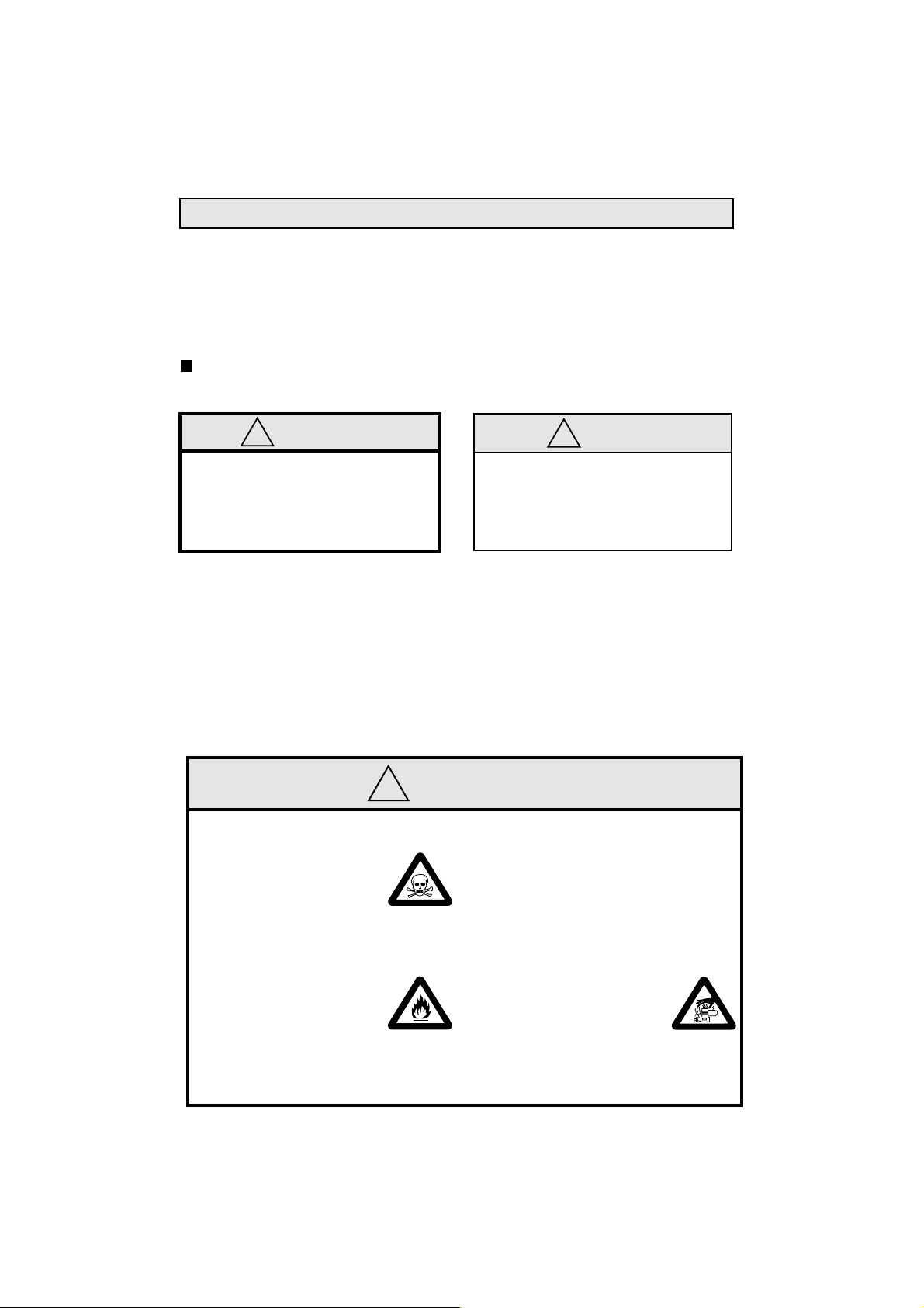
WARNINGS
!
These cover events which
might involve serious (in
extreme circumstances, even
fatal) injury.
!
•
Model engine fuel is poisonous. Do not allow it to
come into contact with the
eyes or mouth. Always store
it in a clearly marked container and out of the reach
of children.
Model engine fuel is also
•
highly flammable. Keep it
away from an open flame,
excessive heat, sources of
sparks, or anything else
which might ignite it. Do not
smoke or allow anyone else
to smoke, near to it.
These cover the many other
possibilities, generally less obvious
sources of danger, but which, under
certain circumstances, may also
cause damage or injury.
2
WARNINGS
•
Never operate your engine in an enclosed space. Model engines, like
automobile engines, exhaust deadly
carbon-monoxide. Run your engine
only in an open area.
Model engines generate
•
considerable heat. Do not
touch any part of your
engine until it has cooled.
Contact with the muffler
(silencer), cylinder head
or exhaust header pipe, in
particular, may result in a
serious burn.
!
NOTES
3
Page 3
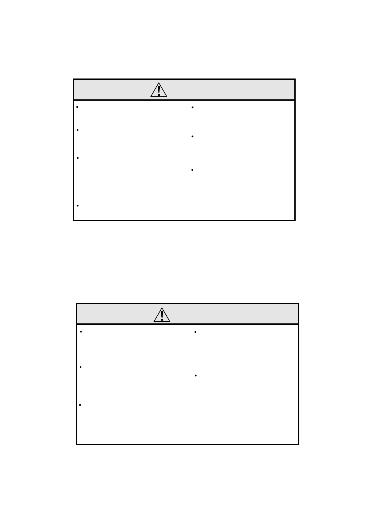
NOTES
This engine is intended for model cars.
Do not attempt to use it for any other
purpose.
Mount the engine in your model
securely, following the manufacturer’s
recommendations, using appropriate
screws and locknuts.
Install an effective silencer (muffler).
Frequent close exposure to a noisy
exhaust (especially in the case of the
more powerful highspeed engines) may
eventually impair your hearing and such
noise is also likely to cause annoyance
to others over a wide area.
The wearing of safety glasses is also
strongly recommended.
Take care that the glowplug clip or
battery leads do not come into contact
with rotating parts. Also check that the
linkage to the throttle arm is secure.
For their safety, keep all onlookers
(especially small children) well back (at
least 20 feet or 6 meters) when
preparing your model for running.
Before starting the engine, always check
the tightness of all the screws and nuts
especially those of joint and movable
parts such as throttle arm. Missing
retightening the loose screws and nuts
often causes the parts breakage that is
capable of harming you.
4
NOTES
To stop the engine, fully retard the
throttle stick and trim lever on the transmitter, or, in an emergency, cut off the
fuel supply by pinching the fuel delivery
line from the tank.
Do not attempt to disassemble the recoil
starter of the 30VG(P)-X. If you do so,
the very strong spring inside will be
suddenly ejected. This can be very
dangerous.
Do not extend the starter cord more than
40cm (16"). Do not abruptly release the
operating handle. Allow the cord to
rewind smoothly while still holding the
handle.
Pull the operating handle straight out
when starting the engine, so that the cord
does not rub against the vehicle body or
engine. This will help prevent the cord
from being damaged by abrasion or
engine heat.
Warning! Immediately after a glowplugignition engine has been run and is still
warm, conditions sometimes exist
whereby it is just possible for the engine to
abruptly restart if it is rotated over
compression WITHOUT the glowplug
battery being reconnected.
5
Page 4
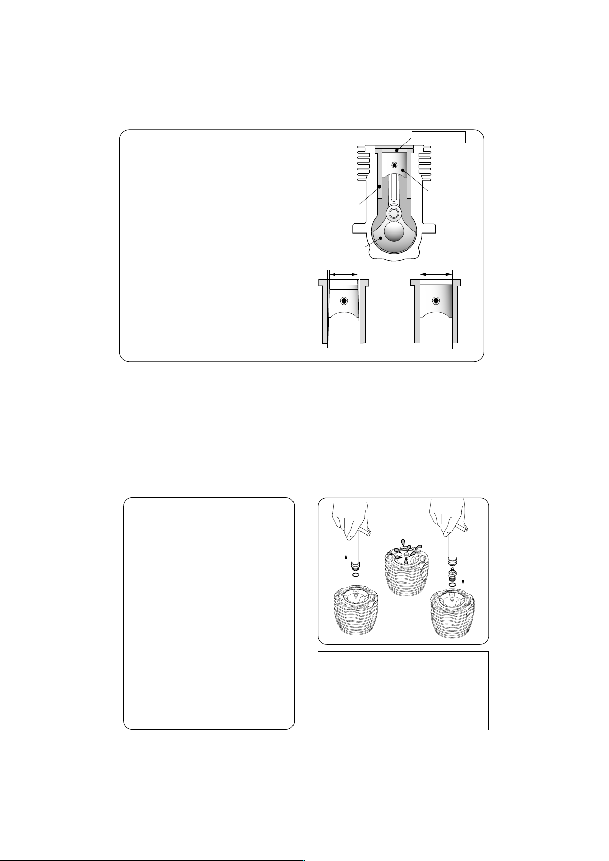
ENGINE CONSTRUCTION
With this engine, the piston
will feel tight at the top of its
stroke (TDC) when the engine
is cold. This is normal. The
cylinder bore has a slight
taper. The piston and cylinder
are designed to achieve a
perfect running clearance
when they reach operating
temperature.
Near TDC
Piston
Cylinder Liner
Crankshaft
Slight taper
NOTES WHEN APPL YING
AN ELECTRIC STARTER
Do not over-prime. This could
cause a hydraulic lock and damage
the engine on application of the
electric starter.
If over-primed, remove glowplug,
close needle-valve and apply
starter to pump out surplus fuel.
Cover the head with a rag to
prevent pumped out fuel getting
into your eyes.
When the engine is cold.
6
NOTE
As delivered, the engine has the
carburetor lightly fit into its intake.
Secure it changing its angle and
outer head position according to the
car chassis.
When the engine is hot.
7
Page 5
MAX-
30VG(P) SERIES INSTRUCTIONS
This manual handles the following three versions.
MAX-30VG(P)
MAX-30VG(P)-X
MAX-30VG(P) SR
(with recoil starter)
(for ROTO STARTER)
ABOUT THE ENGINE
These are rear exhaust and developed for
mainly Monster Trucks. They are the largest
displacement in the O.S. line up for model
cars and offer overwhelming torque and
power. The new 21E carburetor is a single
adjustment type and fitted with a thermo
insulator. It offers stable running.
The engine mount size is the same as the
21 size and easily replaced in most models.
About MAX-30VG(P) SR
This engine is designed to utilize the SAVAGE
ROTO STARTER System #87110 (for S-25
engine).
In case you own a SAVAGE ROTO STARTER
System #87110, remove the back plate unit
#87117 from the System and install it to the
engine.
The back plate unit #87127 from the ROTO
STARTER System #87126 for Nitro Star K
Series cannot be installed to the engine. You
need to purchase a back plate unit #87117
from HPI.
SAVAGE, ROTO STARTER and Nitro Star are the product
name of HPI RACING.
8
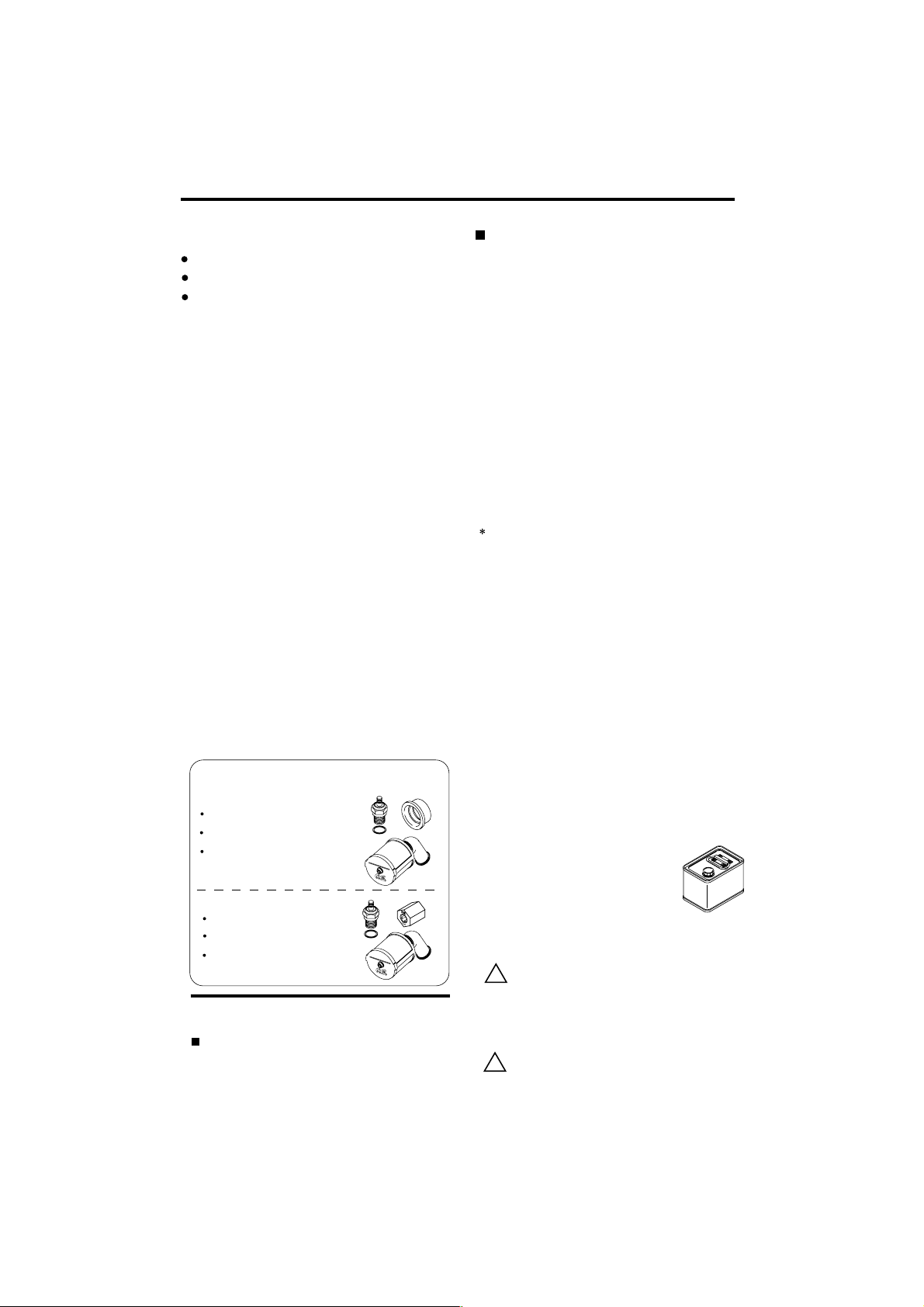
Standard accessories
For
MAX-
30VG(P) /
Glow Plug No.8 1piece
Exhaust Seal Ring 1piece
Super Air Cleaner 203
Assembly
For
MAX-
30VG(P) SR
Glow Plug No.8 1piece
One-way Clutch 1piece
Super Air Cleaner 203
Assembly
MAX-
30VG(P)-X
TOOLS, ACCESSORIES, etc.
The following items are necessary for operating the engine.
Items necessary for starting
FUEL
Generally, it is suggested that the user selects a fuel
that is commercially available for model two-stroke
engines and contains 10-30% nitromethane.
9
As a starting point, we recommend a fuel containing
20% nitromethane, changing to a fuel containing
more nitro if necessary. When the brand of fuel is
changed, or the nitro content increased, it is
advisable to repeat the running-in procedure referred
to in the RUNNING-IN paragraphs. Please note that
with high-nitro fuels, although power
may be increased for competition
purposes, glowplug elements do not
last as long and engine life will be
shorter.
REMINDER!
Model engine fuel is poisonous. Do not
allow it to come into contact with the
eyes or mouth. Always store it in a
!
clearly marked container and out of the
reach of children.
Model engine fuel is also highly
flammable. Keep it away from open
flame, excessive heat, sources of sparks,
!
or anything else which might ignite it. Do
not smoke or allow anyone else to
smoke, near to it.
Page 6
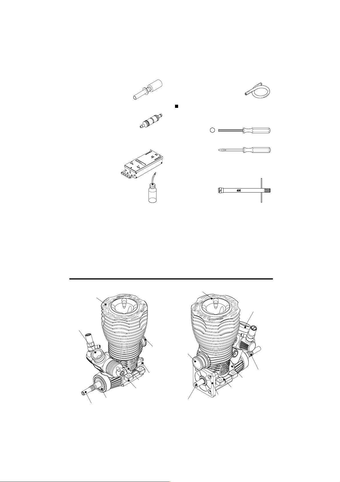
GLOWPLUG IGNITER
Commercialy available handy
glowplug heater in which the
glowplug battery and battery
leads are integrated.
FUEL FILTER
To be installed in the fuel line
between fuel tank and carburetor
to prevent dust from entering the
carburetor.
STARTER BOX
For starting the engine. It is
not necessary for 30VG(P)X and 30VG(P)SR.
FUEL PUMP
For filling the fuel tank, a simple,
polyethylene "squeeze" bottle,
with a suitable spout, is required.
SILICONE FUEL LINE
Heatproof silicone tubing of
approx. 5mm o.d. and 2mm i.d. is
required for the connection
between the fuel tank and engine.
TOOLS
HEX SCREWDRIVER
Necessary for engine installation.
1.5mm, 2mm, 2.5mm, 3mm
SCREWDRIVER
Necessary for carburetor adjustments.
No.1, No.2, etc
LONG SOCKET WRENCH WITH PLUG GRIP
Recommended for easy removal and
replacement of the angled and recessed
glowplug, the O.S.Long Socket Wrench
incorporates a special grip.
10
BASIC ENGINE PARTS
Heatsink Head
Carburetor
Type 21E
Crankshaft Ball Bearing (Front)
Crankshaft
Exhaust
Cover Plate
Crankcase
Mounting Lugs
MAX-
30VG(P)
Heatsink Head
Exhaust
Starting Shaft
11
Mounting Lugs
Rear Adaptor
MAX-
Carburetor
Type 21E
Crankshaft
Crankcase
30VG(P) SR
Page 7
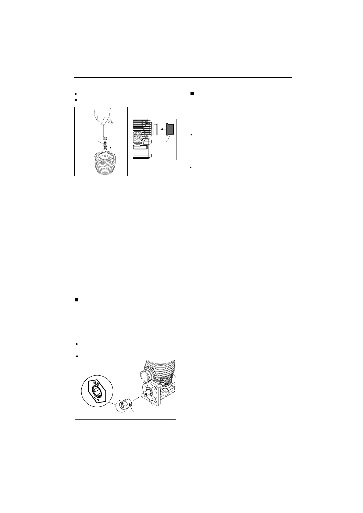
INSTALLATION OF THE STANDARD ACCESSORIES
Installing the glow plug.
Install the exhaust seal ring supplied.
Glowplug
Exhaust
Seal Ring
When the exhaust seal ring supplied cannot
be fitted to the exhaust manifold you have,
use a seal ring supplied with the car kit or
the exhaust manifold.
About the Head Gasket
These engines are equipped with two head
gaskets of 0.2mm thick. It is suggested to
adjust the total thickness according to
atmospheric temperature, humidity and
glowplug used.
At early stage of running-in, when a glowplug
tends to burn out early or when high
nitromethane content fuel is used, try to run
the engine with both gaskets or removing the
0.1mm gasket.
When low nitromethane content fuel is used,
try to run the engine removing one gasket.
12
MAX-30VG(P) SR
Exhaust seal ring is not supplied with the
engine. Use an exhaust seal ring supplied
with the car kit.
Installation of one-way clutch
Inert the one-way clutch on the starting shaft with
the O.S. and an arrow mark facing outside.
Then, install the back plate unit #87117.
Starting Shaft
One-way Clutch
13
Page 8
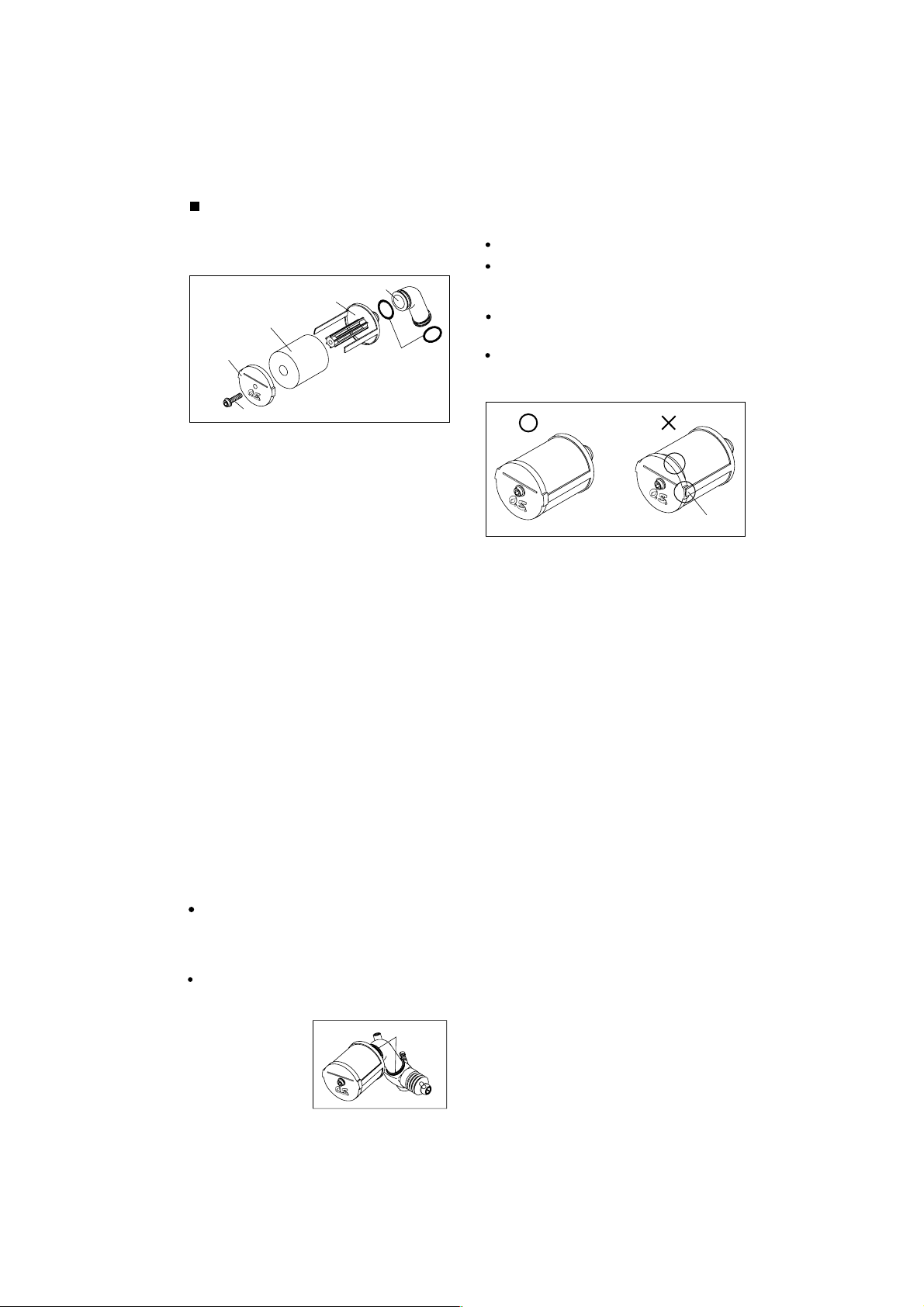
AIR CLEANER TYPE 203
This is a heavy-duty wet type air cleaner
that has been developed specifically for
3.5cc 'off-road' model car engines.
203 Intake Elbow
Element Base
Filter Element
End Plate
Retaining Screw
NOTE:
The element is already impregnated with a
special filter oil. As this oil is very sticky , take
care, when handling it, to pre vent dust or dirt
from adhering to the element. If your fingers
become contaminated, wash them with soap
and water.
"O" Ring
ASSEMBLY
Insert the filter element on the element base.
Install the end plate with retaining screw,
making sure that the element fits correctly
between the end plate and base.
Insert the joint pipe on the element base and
secure it with "O" ring.
Install the end plate, retaining screw, making
sure that the element fits correctly between
the end plate and base.
Element misaligned
14
REPLACMENT OF ELEMENT
NOTE:
During storage, the oil may have become
unevenly dispersed through the element.
This will be indicated if the blue color of the
element material appears patchy. In this
case, place the element in a small plastic bag
and gently rub the element between finger
and thumb to redistribute oil.
It is advisable to replace the filter element after
each hour of running time. Be careful not to
allow dirt and dust to enter the carburetor.
INSTALLATION
Carefully clean the carburetor, removing any
old adhesive or sealant that may have been
previously used on the outside of the air
intake.
"O" Ring
FURTHER PRECAUTIONS
When removing the air cleaner, check the inside
of the element base and carburetor venturi. If
any dirt is detected, this indicates that the filter
element was incorrectly installed or should have
been replaced earlier. In this event, it is vitally
important to wash out the inside of the engine
thoroughly, with alcohol or fuel, before it is used
again, otherwise rapid wear of the
piston/cylinder assenbly, bearings, connectingrod, etc., will occur. Obviously, it will be
necessary to carry out the same procedure with
the air cleaner and to replace the filter element.
NOTE:
Be careful not to splash alcohol or fuel over
the filter element, or the filter oil will be
washed away, and the filter capacity will be
lowered.
15
Page 9

GLOWPLUG
Since the glowplug and fuel combination used
may have a marked effect on performance and
reliability, it would be worthwhile to experiment
with different plug types. An O.S. No.8 glowplug is supplied with the engine. Recommended O.S. plugs are the No.8 and A5. Carefully
install plug finger-tight, before final tightening
with the correct size plug wrench.
The role of the glowplug
With a glowplug engine, ignition is initiated by the
application of a 1.5-volt power source. When the
battery is disconnected, the heat retained within the
combustion chamber remains sufficient to keep the
plug filament glowing, thereby continuing to keep the
engine running. Ignition timing is 'automatic' : under
reduced load, allowing higher rpm, the plug becomes
hotter and, appropriately, fires the fuel/air charge
earlier; conversely, at reduced rpm, the plug become
cooler and ignition is retarded.
Glowplug life
Particularly in the case of very high performance
engines,
glowplugs must be regarded as expendable
items. However, plug life can be extended and engine
performance maintained by careful use, i.e.:
Install a plug suitable for the engine.
Use fuel containing a moderate percentage of
nitromethane unless more is essential for racing
events.
Do not run the engine too lean and do not leave the
battery connected while adjusting the needle.
When to replace the glowplug
Apart from when actually burned out, a plug may
need to be replaced because it no longer delivers its
best performance, such as when:
Filament surface has roughened and turned white.
Filament coil has become distorted.
Foreign matter has adhered to filament or plug
body has corroded.
Engine tends to cut out when idling.
Starting qualities deteriorate.
16
INSTALLATION OF THE CARBURETOR
As delivered, the engine has its carburetor lightly
installed in the intake boss. Secure it as follows.
Loosen the retainer screw, rotate the
1.
carburetor to its correct position and make
sure that it is pressed well down into the
intake boss, compressing the rubber gasket,
before retightening screw.
Rotate the retainer screw gently until it
2.
stops, then tighten a further 120-180 .
Do not overtighten the screw as this will
damage the carburetor body.
Rotate the retainer nut
gently until it stops.
Tighten a further
120-180
17
Note
Be careful not to damage the O rings when
removing the carburetor retainer from the
engine.
First, remove the retainer Retaining screw,
then pull out each part. Do not push the
part in or damage the O rings.
"O" Ring
"O" Ring
Retaining Screw
Page 10

ENGINE INSTALLATION
Make sure that the vehicle’s engine mounting
surfaces are level and in the same plane. Poor
installation may cause distortion of the
crankcase, bearings, etc., resulting in erratic
running and loss of performance.
The recommended screws for securing the
engine are 3mm or 4-40 steel Allen hexagon
socket type.
If existing holes in the engine mount do not align
perfectly with engine mounting lugs, enlarge
them slightly with a needle-file so that screws are
in alignment with the mounting holes.
Do not allow bottom
of crankcase to
touch chassis.
Chassis
Chamfer inside edges of bearers.
NOTES CONCERNING THE RECOIL STARTER
REMINDER!
Do not attempt to disassemble the recoil starter.
If you do so, the very strong spring inside will be
suddenly ejected. This can be very dangerous.
Do not extend the starter cord more than 40cm
(16"). Do not abruptly release the operating
handle. Allow the cord to rewind smoothly while
still holding the handle.
Pull the operating handle straight out when
starting the engine, so that the cord does not
rub against the vehicle body or engine.
This will help prevent the cord from being
damaged by abrasion or engine heat.
Try to avoid spilling fuel over the starter unit and
its cord. Some fuels have a detrimental effect on
these parts.
The starter prevents the engine from being rotated in the wrong direction.The unit will be
damaged if you attempt to force the flywheel in
the opposite direction (i.e. clockwise when
viewed from the crankshaft end).
18
( 30VG(P)-X ONLY)
CARBURETOR CONTROLS 21E
Needle Valve
Fuel Inlet
Metering Needle
Ball Link
Mixture Control Screw
Thermo Insulator
Three adjustable controls are provided on
this carburetor.
The Needle-Valve
For adjusting the mixture strength when the
throttle is fully open.
The Metering Needle:
(Adjusted at the factory):
For adjusting the mixture strength at partthrottle and idle speed, to obtain steady
idling and smooth acceleration to mid speed.
The Mixture Control Screw:
(Adjusted at the factory):
For setting the minimum idle speed:
NOTE: Readjustment may be necessary,
occasionally to allow for changes in fuel
formula, gear ratio or clutch engagement
point.
19
Page 11

STARTING THE ENGINE & RUNNING-IN ('Breaking-in)
Lay the chassis on a stand and start the
engine so that the tires are not in contact
with the ground.
Running- in is a procedure for an engine to
come close to actual running conditions
(fuel, r.p.m., engine temperature, etc.).
Excessively rich running and prolonged
low speed running should be avoided.
Prolonged low speed running and low
temperature running may result in the oil in
the fuel being gelled and piston/liner being
glued together.
PRESSURIZED FUEL SYSTEM
The somewhat violent changes of vehicle
attitude that occur in off-road running,
combined with the fact that, in buggy type
cars, the fuel tank is often located some
distance from the carburetor, means that fuel
'head' at the carburettor can vary and upset
running.Therefore,it is recommended that a
muffler pressurized fuel feed system be used.
Never run your vehicle without installing the
air cleaner. Dust and dirt that may otherwise
be drawn into the engine will rapidly shorten
its life.
Before starting the engine, always
check the tightness of all the screws
and nuts especially those of joint and
!
movable parts such as throttle arm.
Missing retightening the loose screws
and nuts often causes the parts breakage that is capable of harming you.
20
The following procedure is suitable when a
fuel containing up to 30% nitromethane is
used.
Lay the chassis on a stand and start the
engine so that the tires are not in contact
with the ground.
stand
Fill the tank completely with fuel.
Fuel Pump
Fuel Tank
Temporarily remove the glowplug to check
that it glows bright red when energized.
Element glows when energized.
Pliers
Replace the plug when the
element does not glow or is
burnt out.
Glow Plug Igniter
Do not hold a glowplug with fingers and
use pliers when checking the brightness. Do not have your face close to the
glowplug or boiled fuel remaining in the
coil will burn you.
21
Page 12

The carburetor is set as shown below at the
factory. Start the engine as it is.
The needle-valve is set approx. 2-3/4 turns
opened from the fully closed position.
Turn the needle-valve clockwise until it stops. This
is the fully closed position. Do not force it to turn
further.
Close (clockwise)
Note
Check the throttle opening at idle before installing an air cleaner. After the engine is
started, be sure to install an air cleaner.
If the fuel tank is equipped with a choke
button, push the button to send the fuel to the
carburetor. If not, apply an electric starter to
send the fuel to the carburetor.
Open
Needle Valve
Throttle is set approx. 0.5mm open.
approx 0.5mm
Approx. 0.5mm open
factory setting
Metering needle is set at basic position.
(Refer to P28.)
In case of the 30VG(P)
Start the engine using a starter box, making
sure the engine rotation direction is correct
(counter-clockwise seen from the crankshaft
end). Be sure to install an air cleaner when
starting.
In case of the 30VG(P)-X
Pull the starter handle
briskly straight out
several times to start
the engine.
In case of the 30VG(P) SR
Starter Handle
Use the ROTO STARTER to start the engine.
Attention:
It is vitally important to set
the throttle at the correct
position before starting the
engine. If the engine is
allowed to run with the
throttle too far open under
Deliver fuel into the carburetor.
Fuel
Fuel tank side
Now connect glowplug battery lead to heat
the plug filament and start the engine.
22
''no load'' conditions (i.e. with the driving wheels
not in contact with
the ground) it will rapidly
over-heat and may be seriously damaged.
When the engine starts, first allow it to
operate in short runs at the very rich starting
settings, with the glowplug battery still
connected and the driving wheels clear of
the ground. The rich mixture will, under
these conditions, provide adequate
lubrication and cooling, indicated by profuse
smoke from the exhaust.
Next, disconnect the glowplug battery and try
◆
running the car on the track. If the engine
stalls, open the throttle fractionally, but try to
keep the engine running as rich as possible: if
it stops because of being excessively overrich, close the Needle-Valve 30 and try again.
23
Page 13

Run the car on the track until one tank of fuel
has been consumed, then close the NeedleValve 30 and run the car for another full
tank of fuel. Repeat this procedure until 1/2
gallon of fuel have been consumed, during
which time the throttle may be opened for
brief bursts of increased power.
The position of the needle-valve
Needle
when starting the engine.
Close the needle-valve approx.
30 after running the vehicle for
one full tank of fuel.
Repeat this procedure several
times.
Note:
If the engine should need to be
disassembled (e.g. for cleaning or minor
parts replacement), it is advisable to return
the needle-valve to the original rich,
starting setting and check whether further
running-in time is required before the car is
raced again. In the event of any major
working parts (e.g. piston/cylinder liner
assembly) being replaced or the fuel being
changed, especially to high nitro fuel, the
complete running-in should be repeated.
To stop the engine, close the throttle to idle
speed, then shut it off completely with the
trim lever on the transmitter. To cut off the
fuel supply, pinch the fuel delivery tube to
the carburetor.
Fuel
Warning!
Do not touch rotating parts, engine and
silencer when stopping the engine as they
become very hot, and contact with them
may result in a serious burn.
24
FINAL ADJUSTMENT
Final adjustment should be carried out only after
the running-in has been completed.
Needle Valve
Open
More fuel
Needle Valve
Close
Less fuel
Metering Needle
Metering Needle
Open
More fuel Less fuel
Close
Run the vehicle (with throttle fully open) over
the longest available straight course, in order
to observe the model's speed. Next return
the car to the starting point, close the NeedleValve 30 and repeat the run, taking note of
the improvement in performance.
Continue with further runs, gradually
reducing the Needle-Valve setting and
aiming to achieve the highest straight-line
speed. Remember, however, that, if the
Needle-Valve is shut down too far, the
engine will overheat and, accompanied by
visibly diminished exhaust smoke, the model
will lose speed. At this point, throttle down
immediately, stop the vehicle and reopen the
Needle-Valve 45~90 .
Note
Be sure to set the needle-valve a little open
from the optimum position so that the mixture
may become a little rich.
25
Page 14

With the engine running, close the throttle
and allow it to idle for about five seconds,
then reopen the throttle fully. If, at this point,
the engine puffs out an excessive amount of
smoke and the vehicle does not accelerate
smoothly and rapidly, it is probable that the
idle mixture is too rich. In this case, turn the
Metering Needle clockwise 45-90 . If, on the
other hand, the engine tends to speed up
momentarily and then cut out abruptly when
the throttle is opened, the idle mixture is too
lean. Correct this by turning the Metering
Needle counter-clockwise 45-90 .
NOTE:
Metering Needle adjustment should be
made in steps of not more than 45-90 ,
carefully checking the effect,on throttle
response, of each small adjustment.
Carry out adjustments patiently, under actual
running conditions, until the engine
responds quickly and positively to the
throttle control.
Warning!
Mixture adjustments (whether via the
Metering Needle, or the Needle-Valve)
cannot be made accurately under 'no-load'
conditions, which, in any case, are not
advised, since such operation carries the
risk of seriously damaging the engine
through over-revving and overheating.
26
With the optimum mixture control position,
light smoke is visible during high speed
running,and the engine rpm increases
smoothly during acceleration. Remember
that, if the engine is operated with the fuel/air
mixture slightly too lean, it will overheat and
run unevenly. As with all engines, it is
advisable to set both the needle-valve and
metering needle slightly on the rich side of
the best rpm setting, as a safety measure.
If the engine runs too fast with the throttle
closed, the Mixture Control screw should be
turned counter-clockwise to allow the throttle
opening to be reduced.
Finally, beyond the nominal break-in period,
a slight readjustment toward a leaner needle
setting may be required to maintain
maximum performance.
NOTE
The above mentioned needle opening is a
guide. It varies according to the fuel used and
silencer. Usually, when a lower nitro content
fuel used, it will be necessary to close the
needle-valve.
Do not close the needle-valve too much or
rust will be generated and the engine will be
damaged.
27
Page 15

CARBURETOR CLEANLINESS
The correct functioning of the carburetor
depends on its small fuel orifices remaining
clear.
REALIGNMENT OF METERING NEEDLE
In the course of making carburetor
adjustments, it is just possible that the Metering
Needle may be inadvertently screwed in or out
too far and thereby moved beyond its effective
adjustment range. The basic positions can be
found by rotating the Metering Needle until its
slotted head is flush with the ball link body.
Carburetor Body
Slide Valve
Ball Link
First rotate the Mixture
Control Valve until its
slotted head is flush with
the ball link outer face.
Then screw the valve in
exactly 1.5 turns (0.75mm).
This is the standard
Metering
position.
Needle
CARE AND MAINTENANCE
In case of the 30VG(P) and 3
Do not forget to clean the filters regularly to remove
dirt and lint that accumulate on the filter screens.
Also, clean the carburetor itself occasionally.
At the end of each operating session, drain out any
fuel that may remain in the fuel tank.
Afterwards,energize the glow-plug and try to restart
the engine, to burn off any fuel that may remain
inside the engine. Repeat this procedure until the
engine fails to fire. Do this while the engine is still
warm.
Then, inject some after-run oil into the engine, and
rotate the engine with an electric starter for 4 to 5
seconds to distribute the oil to all the working
parts.
0VG(P) SR
28
In case of the 30VG(P)-X
Do not forget to clean the filters regularly to remove
dirt and lint that accumulate on the filter screens.
Also, clean the carburetor itself occasionally.
At the end of each operating session, drain out any
fuel that may remain in the fuel tank.
Afterwards,energize the glow-plug and try to restart
the engine, to burn off any fuel that may remain
inside the engine. Repeat this procedure until the
engine fails to fire. Do this while the engine is still
warm.
Then, inject some after-run oil into the engine, and
rotate the engine pulling the recoil starter to
distribute the oil to all the working parts.
29
Page 16

Note:
Do not inject after-run oil into the carburetor as
this may cause the O-rings inside the carburetor
to deteriorate. These procedures will reduce the
risks of starting difficulties or corrosion after a
period of storage.
Finally, when cleaning the exterior of the
engine, use methanol or kerosene. Do not
use gasoline or any solvent that might
damage the silicone fuel tubing.
Installing Dust Caps
(Optional extra)
When storing the engine, install the cap on
the exhaust port, carburetor, etc. to prevent
dust from entering the engine.
The minute particles of foreign matter, that are
present in any fuel may, by accumulating and
partially obstructing fuel flow, cause engine
performance to become erratic and unreliable.
O.S. 'Super-Filters' (large and small) are
available, as optional extras, to deal with this
problem.
One of these filters installed to the pickup tube
inside your refueling container, will prevent the
entry of foreign material into the fuel tank. It is
also recommended that a good in-line filter be
installed between the tank and carburetor.
Dirt and dust may lodge in marked places.
30
CHECKING THE ENGINE
If the engine suffers a loss of performance
after a long period of running it may be due to
the wearing of parts. It is suggested that the
worn parts be replaced when the following
symptoms are detected.
Engine sound changes and easily overheats.
Power has dropped considerably.
Idle is unstable and/or engine tends to stop
at idle.
In most cases, ball bearings, cylinder & piston
assembly, connecting rod and/or crankcase
have become worn out or abnormal. Check
the parts carefully and replace them if necessary.
31
Page 17

TROUBLE SHOOTING
Cause
Fuel tank is empty.
Fuel not reaching the engine.
Glowplug element is burnt out.
Glowplug battery discharged
Clogged fuel filter
Air cleaner and silencer inside is dirty.
Over priming Remove glowplug and pump out excess fuel.
Fill the tank with fuel and repeat
Priming procedure.
Replace glowplug.
Recharge or replace the battery.
Clean or replace fuel filter.
Replace cleaner element and clean inside silencer.
Symptom
Engine fails to fire.
Corrective action
Fuel tubing is disconnected.
Fuel tubing is kinked, split or has a hole.
Incorrect carburetor settings
Incorrect servo linkage
Reverse rotating direction of electric starter.
Symptom
Engine fires intermittently but does not run.
Cause
Insufficient fuel in the tank. Fill the tank with fuel.
Connect fuel tubing securely.
Check the tubing carefully and replace if necessary.
Return the metering needle
and mixture control valve to basic position.
adjust linkage after setting servo at neutral.
Mare sure it rotates counter clockwise seen
from crankshaft side.
32
Corrective action
Deteriorated glowplug
Clogged fuel filter
Air cleaner and silencer inside is dirty.
Engine overheated
Incorrect clutch release
Glowplug battery disconnecting too soon
Fuel foaming in tank
Replace glowplug.
Clean or replace fuel filter.
Replace cleaner element and clean inside silencer.
Wait until engine is cooled.
Adjust the tension of clutch spring.
Do not disconnect plug battery and wait until
r.p.m. become stable.
Fit O rings to the tank screws to
prevent foaming.
33
Page 18

Symptom
Unstable idle
Cause
Corrective action
Unsuitable glowplug
Unsuitable fuel
Extremely light flywheel Use heavier flywheel.
Silencer is disconnected or has play
Symptom
Not reaching expected peak r.p.m.
Cause
Insufficient warming up or running-in.
Silencer or manifold is not securely connected
or disconnected.
Fuel tubing from tank to is split or broken.
Use suggested glowplug in the instructions.
Do not use extremely high nitro or low oil fuel.
Install silencer securely.
Corrective action
Set the needle only after warming up.
Complete running-in.
Replace seal ring.
Check the connections and secure them.
Replace the tubing.
34
Symptom
Poor response
Cause
Deteriorated glowplug
Incorrect carburetor settings
Incorrect setting of transmitter Exponential function.
Symptom
Poor r.p.m. drop
Cause
Throttle open too far at idle.
Incorrect carburetor fitting
Corrective action
Replace glowplug.
Readjust low r.p.m. range with metering
needle and mixture control valve.
Check the transmitter setting.
Corrective action
Close metering needle to adequate position
to lower idle r.p.m.
Fit carburetor securely.
35
Page 19

36
MAX-
30VG(P) ENGINE EXPLODED VIEW
C.M3x18
1
2
3
5
4
7
8
9
6
11
C.M2.6x18
10
MAX-
30VG(P) ENGINE PARTS LIST
No.
Code No.
1
23924000
2
23914100
3
23923000
4
23916000
5
24517000
6
7
8
9
10
11
12
13
14
15
23915000
23981000
23981740
23731000
23911000
23730010
23912000
23764020
23927000
23763010
C.M2.6x7
15
37
71608001
14
13
12
22826140
72413000
72413200
The specifications are subject to alteration for improvement without notice.
Heatsink Head
Head Gasket
Cylinder & Piston Assembly
Piston Pin
Piston Pin Retainer (2pcs.)
Connecting Rod
Carburetor Complete (Type 21E)
Carburetor Retainer Assembly
Crankshaft Ball Bearing (Front)
Crankcase
Crankshaft Ball Bearing (Rear)
Crankshaft
Cover Gasket
Cover Plate
Screw Set
Glow Plug No.8
Exhaust Seal Ring
Super Air Cleaner 203 Assembly (W/2 filter elements)
203 Filter Elements (4pcs.)
Description
Type of screw
C...Cap Screw M...Oval Fillister-Head Screw
F...Flat Head Screw N...Round Head Screw S...Set Screw
Page 20

MAX-
30VG(P)-X ENGINE EXPLODED VIEW
C.M3x18
1
2
38
Type of screw
C...Cap Screw M...Oval Fillister-Head Screw
F...Flat Head Screw N...Round Head Screw S...Set Screw
5
4
7
9
8
10
6
C.M2.6x18
15
3
11
M.+M2.6x7
12
16-2
13
16
14
M.+M2.6x6
16-1
MAX-
30VG(P)-X ENGINE PARTS LIST
No.
Code No.
1
23924000
2
23914100
3
23923000
4
23916000
5
24517000
6
23915000
7
23981000
8
23981740
9
23731000
10
23911000
11
23730010
12
17
39
13
14
15
16
16-1
16-2
17
23912010
23764020
23912100
23927100
73009000
73009100
73008200
23911300
71608001
22826140
72413000
72413200
The specifications are subject to alteration for improvement without notice.
Heatsink Head
Head Gasket
Cylinder & Piston Assembly
Piston Pin
Piston Pin Retainer (2pcs.)
Connecting Rod
Carburetor Complete (Type 21E)
Carburetor Retainer Assembly
Crankshaft Ball Bearing (Front)
Crankcase
Crankshaft Ball Bearing (Rear)
Crankshaft
Cover Gasket
Starting Shaft
Rear Adaptor
N3 Recoil Starter Assembly
N3 Recoil Starter Body
One-way Clutch
Screw Set
Glow Plug No.8
Exhaust Seal Ring
Super Air Cleaner 203 Assembly (W/2 filter elements)
203 Filter Elements (4pcs.)
Description
Page 21

MAX-
30VG(P) SR ENGINE EXPLODED VIEW
MAX-
30VG(P) SR ENGINE PARTS LIST
C.M3x18
1
2
40
5
4
7
9
8
10
Type of screw
C...Cap Screw M...Oval Fillister-Head Screw
F...Flat Head Screw N...Round Head Screw S...Set Screw
6
C.M2.6x18
No.
Code No.
23924000
1
23914100
2
23923000
3
23916000
4
24517000
5
23915000
6
23981000
7
23981740
8
23731000
9
23911000
41
10
11
12
13
14
15
16
23730010
23912010
23764020
23912200
23917200
23911300
16
3
71608001
73008200
11
14
13
12
M.+M2.6x7
15
72413000
72413200
The specifications are subject to alteration for improvement without notice.
Heatsink Head
Head Gasket
Cylinder & Piston Assembly
Piston Pin
Piston Pin Retainer (2pcs.)
Connecting Rod
Carburetor Complete (Type 21E)
Carburetor Retainer Assembly
Crankshaft Ball Bearing (Front)
Crankcase
Crankshaft Ball Bearing (Rear)
Crankshaft
Cover Gasket
Starting Shaft (For Roto Start)
Rear Adaptor (For Roto Start)
Screw Set
Glow Plug No.8
One-way Clutch
Super Air Cleaner 203 Assembly (W/2 filter elements)
203 Filter Elements (4pcs.)
Description
Page 22

21E CARBURETOR EXPLODED VIEW
2-1
2-2
2
2-3
2-4
1
3
8
9
5
4
5-1
6
Type of screw
C...Cap Screw M...Oval Fillister-Head Screw
F...Flat Head Screw N...Round Head Screw S...Set Screw
21E CARBURETOR PARTS LIST
No.
Code No.
23981620
1
22781800
1-1
23618190
2
23618197
2-1
46066319
2-2
23618194
2-3
23818176
2-4
23981100
3
23981200
4
23981500
5
27881820
5-1
23981520
6
23781400
7
23781110
8
29015019
9
The specifications are subject to alteration for improvement without notice.
Mixture Control Screw
"O" Ring (S) (2pcs.)
Needle Valve Assembly
Needle Assembly
"O" Ring (2pcs.)
Needle Holder Assembly
Fuel Inlet
Carburetor Body
Slide Valve
Metering Needle Assembly
"O" Ring (2pcs.)
Dust Cover
Ball Link (No.3)
Thermo Insulator
Carburetor Rubber Gasket
S.M3x3
7
42
Description
43
Page 23

O.S. GENUINE PARTS & ACCESSORIES
O.S. Glow Plug
No.8
(71608001)
A5
(71605100)
Dust Cap Set
(5pcs.)
(73300305)
3
(3pcs.)
8
(73300812)
(3pcs.)
(3pcs.)
(73301612)
(73301812)
16
18
Super Air Cleaner 203 Assembly
(72413000)
203 Filter Element (4pcs.)
(72413200)
Cap Screw Set
Off-road T ype
(10pcs.)
M2.6x7
(79871020)
M2.6x18
(79871055)
The specifications are subject to alteration for improvement without notice.
44
Exhaust Seal Ring
(22826140)
Thermo Insulator
(23781110)
Long Socket Wrench
With Plug Grip
(71521000)
(2pcs.)
MAX-
30VG(P
SPECIFICATIONS
Displacement
■
■
Bore
■
Stroke
■
Practical R.P.M.
■
Power output
■
Weight
)
THREE VIEW DRAWING
5.0 cc (0.298 cu.in.)
18.5mm (0.728 in.)
18.2mm (0.717 in.)
4,000-36,000 r.p.m.
3.0 ps / 28,000 r.p.m.
360g (12.7oz.)
97.7
30.8
45
UNF1/4-28
45
29.5
21
44 21.6
59
37
Dimensions (mm)
Page 24

MAX-
30VG(P)-X
SPECIFICATIONS
Displacement
■
Bore
■
Stroke
■
Practical R.P.M.
■
Power output
■
Weight
■
THREE VIEW DRAWING
5.0 cc (0.298 cu.in.)
18.5mm (0.728 in.)
18.2mm (0.717 in.)
4,000-36,000 r.p.m.
3.0 ps / 28,000 r.p.m.
408g (14.4oz.)
97.7
59
37
21
UNF1/4-28
MAX-
30VG(P) SR
SPECIFICATIONS
Displacement
■
Bore
■
Stroke
■
Practical R.P.M.
■
Power output
■
Weight
■
45
THREE VIEW DRAWING
5.0 cc (0.298 cu.in.)
18.5mm (0.728 in.)
18.2mm (0.717 in.)
4,000-36,000 r.p.m.
3.0 ps / 28,000 r.p.m.
399g (14.1oz.)
97.7
46
29.5
44
38.5
Dimensions (mm)
59
37
21
UNF1/4-28
6
45
29.5
44
21.3
Dimensions (mm)
47
Page 25

MEMO
48
C
Copyright 2005 by O.S.Engines Mfg. Co., Ltd. All rights reserved. Printed in Japan.
6-15 3-Chome Imagawa Higashisumiyoshi-ku
Osaka 546-0003, Japan
URL : http://www.os-engines.co.jp
TEL. (06)6702-0225
FAX. (06)6704-2722
60091710 010601
 Loading...