

Page 1
Page 2

3510 Vauxhall/Opel Omega
Vauxhall/Opel Omega
Service and Repair Manual
Mark Coombs and Spencer Drayton
Models covered
Vauxhall Omega Saloon and Estate models with petrol engines, including special/limited editions
1998 cc, 2498 cc & 2969 cc petrol engines
Does not cover diesel engine or bi-fuel (LPG) models
(3510 - 352)
ABCDE
FGHIJ
KLMNO
PQRST
1 2 3
© Haynes Publishing 1999
A book in the Haynes Service and Repair Manual Series
All rights reserved. No part of this book may be reproduced or transmitted
in any form or by any means, electronic or mechanical, including
photocopying, recording or by any information storage or retrieval system,
without permission in writing from the copyright holder.
ISBN 1 850960 510 9
British Library Cataloguing in Publication Data
A catalogue record for this book is available from the British Library.
Printed by J H Haynes & Co. Ltd, Sparkford, Nr Yeovil, Somerset BA22 7JJ
Haynes Publishing
Sparkford, Nr Yeovil, Somerset BA22 7JJ, England
Haynes North America, Inc
861 Lawrence Drive, Newbury Park, California 91320, USA
Editions Haynes S.A.
Tour Aurore - La Défense 2, 18 Place des Reflets,
92975 PARIS LA DEFENSE Cedex France
Haynes Publishing Nordiska AB
Box 1504, 751 45 UPPSALA, Sverige
Page 3

3510 Vauxhall/Opel Omega
Contents
LIVING WITH YOUR VAUXHALL OMEGA
Introduction Page 0•4
Safety First! Page 0•5
Roadside Repairs
Introduction Page 0•6
If your car won’t start Page 0•6
Jump starting Page 0•7
Wheel changing Page 0•8
Identifying leaks Page 0•9
Towing Page 0•9
Weekly Checks
Introduction Page 0•10
Underbonnet check points Page 0•10
Engine oil level Page 0•11
Coolant level Page 0•11
Brake (and clutch) fluid level Page 0•12
Power steering fluid level Page 0•12
Battery Page 0•13
Electrical systems Page 0•13
Tyre condition and pressure Page 0•14
Tyre tread wear patterns Page 0•14
Washer fluid level Page 0•15
Wiper blades Page 0•15
Lubricants and fluids Page 0•16
Tyre pressures Page 0•17
MAINTENANCE
Routine Maintenance and Servicing
Servicing specifications Page 1•2
Maintenance schedule Page 1•3
Maintenance procedures Page 1•6
Page 4

3510 Vauxhall/Opel Omega
Contents
REPAIRS & OVERHAUL
Engine and Associated Systems
2.0 litre SOHC engine in-car repair procedures Page 2A•1
2.0 litre DOHC engine in-car repair procedures Page 2B•1
2.5 and 3.0 litre engine in-car repair procedures Page 2C•1
General engine overhaul procedures Page 2D•1
Cooling, heating and ventilation systems Page 3•1
Fuel and exhaust systems Page 4A•1
Emission control systems Page 4B•1
Starting and charging systems Page 5A•1
Ignition system Page 5B•1
Transmission
Clutch Page 6•1
Manual transmission Page 7A•1
Automatic transmission Page 7B•1
Final drive, driveshafts and propeller shaft Page 8•1
Brakes and Suspension
Braking system Page 9•1
Suspension and steering Page 10•1
Body equipment
Bodywork and fittings Page 11•1
Body electrical system Page 12•1
Wiring Diagrams Page 12•23
REFERENCE
Dimensions and weights Page REF•1
Conversion Factors Page REF•2
Buying Spare Parts and Vehicle Identification Page REF•3
General Repair Procedures Page REF•4
Jacking and vehicle support Page REF•5
Radio/cassette unit anti-theft system precaution Page REF•5
Tools and working facilities Page REF•6
MOT Test Checks Page REF•8
Fault Finding Page REF•12
Glossary of Technical Terms Page REF•20
Index Page REF•24
Page 5
0•4 Introduction
3510 Vauxhall/Opel Omega
The Vauxhall Omega was introduced into the UK in April of 1994 as a
replacement for the Vauxhall Carlton and Senator. At its launch, the
Omega was available in both Saloon and Estate body styles with a
choice of either 2.0 litre (1998 cc) or a 2.5 litre (2498 cc) petrol engine
both available with either a 5-speed manual transmission unit or a 4speed automatic transmission unit. Shortly afterwards a 3.0 (2968 cc)
litre petrol engine was also introduced. A 2.5 litre Diesel engine (not
covered in this manual) was also available. The petrol engines are all
well-proven units which are used in many other Vauxhall vehicles; the
engine is mounted at the front of vehicle with the transmission
mounted on its rear.
Two versions of the four-cylinder 2.0 litre engine were used; low
specification vehicles were fitted with a single overhead camshaft
(SOHC) 8-valve engine were as all other vehicles were fitted with the
double overhead camshaft (DOHC) 16-valve engine often referred to as
the ECOTEC engine. The 2.5 and 3.0 litre engines are both V6, double
overhead camshaft (DOHC) units which are also often referred as
ECOTEC engines.
All models have fully-independent front and rear suspension and are
equipped with front and rear disc brakes.
A wide range of standard and optional equipment is available within
the range to suit most tastes, including central locking, electric
windows and an electric sunroof. An air conditioning system was
available as an option on certain models.
Provided that regular servicing is carried out in accordance with the
manufacturer’s recommendations, the vehicle should prove reliable
and very economical. The engine compartment is well-designed, and
most of the items requiring frequent attention are easily accessible.
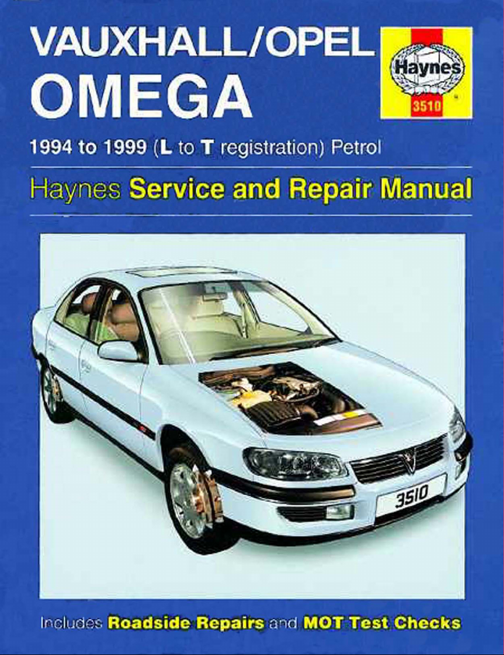
Vauxhall Omega 2.0 16V Select
Vauxhall Omega Estate CD
Your Vauxhall Omega manual
The aim of this manual is to help you get the best value from your
vehicle. It can do so in several ways. It can help you decide what work
must be done (even should you choose to get it done by a garage). It
will also provide information on routine maintenance and servicing, and
give a logical course of action and diagnosis when random faults
occur. However, it is hoped that you will use the manual by tackling the
work yourself. On simpler jobs it may even be quicker than booking the
car into a garage and going there twice, to leave and collect it. Perhaps
most important, a lot of money can be saved by avoiding the costs a
garage must charge to cover its labour and overheads.
The manual has drawings and descriptions to show the function of
the various components so that their layout can be understood. Tasks
are described and photographed in a clear step-by-step sequence.
References to the ‘left’ and ‘right’ are in the sense of a person in the
driver’s seat, facing forwards.
Acknowledgements
Thanks are due to Champion Spark Plug, who supplied the
illustrations showing spark plug conditions. Certain illustrations are the
copyright of Vauxhall Motors Limited, and are used with their
permission. Thanks are also due to Draper Tools Limited, who
provided some of the workshop tools, and to all those people at
Sparkford who helped in the production of this manual.
We take great pride in the accuracy of information given in this
manual, but vehicle manufacturers make alterations and design
changes during the production run of a particular vehicle of which
they do not inform us. No liability can be accepted by the authors
or publishers for loss, damage or injury caused by any errors in, or
omissions from, the information given.
The Vauxhall Omega Team
Haynes manuals are produced by dedicated and
enthusiastic people working in close co-operation. The
team responsible for the creation of this book included:
Authors Marc Coombs
Spencer Drayton
Sub-editor Ian Barnes
Editor & Page Make-up Steve Churchill
Workshop manager Paul Buckland
Photo Scans Steve Tanswell
John Martin
Cover illustration & Line Art Roger Healing
Wiring diagrams Matthew Marke
We hope the book will help you to get the maximum
enjoyment from your car. By carrying out routine
maintenance as described you will ensure your car’s
reliability and preserve its resale value.
Page 6
Safety first! 0•5
3510 Vauxhall/Opel Omega
Working on your car can be dangerous.
This page shows just some of the potential
risks and hazards, with the aim of creating a
safety-conscious attitude.
General hazards
Scalding
• Don’t remove the radiator or expansion
tank cap while the engine is hot.
• Engine oil, automatic transmission fluid or
power steering fluid may also be dangerously
hot if the engine has recently been running.
Burning
• Beware of burns from the exhaust system
and from any part of the engine. Brake discs
and drums can also be extremely hot
immediately after use.
Crushing
• When working under or near
a raised vehicle,
always
supplement the
jack with axle
stands, or use
drive-on
ramps.
Never
venture
under a car which
is only supported by a jack.
• Take care if loosening or tightening hightorque nuts when the vehicle is on stands.
Initial loosening and final tightening should be
done with the wheels on the ground.
Fire
• Fuel is highly flammable; fuel vapour is
explosive.
• Don’t let fuel spill onto a hot engine.
• Do not smoke or allow naked lights
(including pilot lights) anywhere near a
vehicle being worked on. Also beware of
creating sparks
(electrically or by use of tools).
• Fuel vapour is heavier than air, so don’t
work on the fuel system with the vehicle over
an inspection pit.
• Another cause of fire is an electrical
overload or short-circuit. Take care when
repairing or modifying the vehicle wiring.
• Keep a fire extinguisher handy, of a type
suitable for use on fuel and electrical fires.
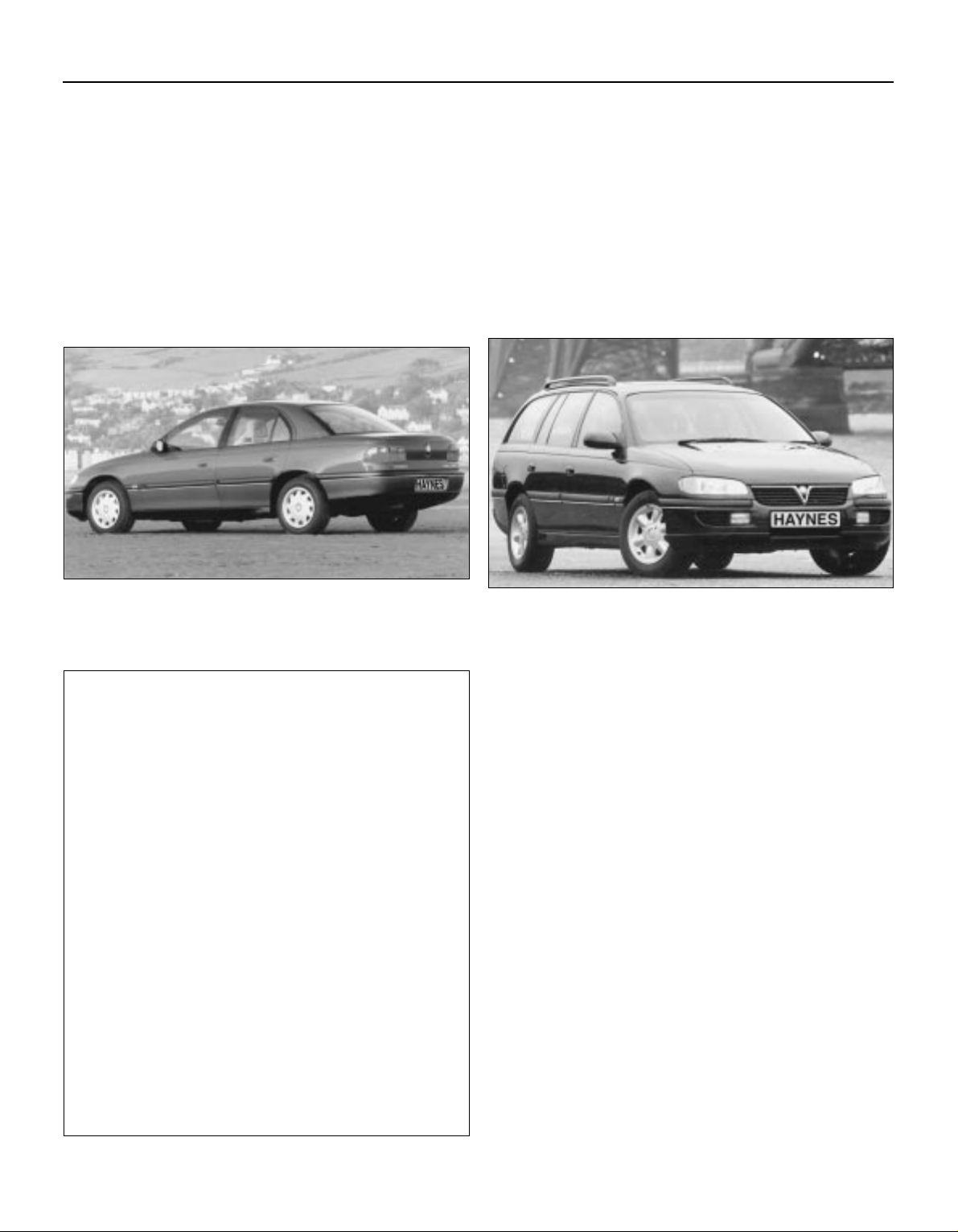
Electric shock
• Ignition HT
voltage can be
dangerous,
especially to
people with heart
problems or a
pacemaker. Don’t
work on or near the
ignition system with
the engine running or
the ignition switched on.
• Mains voltage is also dangerous. Make
sure that any mains-operated equipment is
correctly earthed. Mains power points should
be protected by a residual current device
(RCD) circuit breaker.
Fume or gas intoxication
• Exhaust fumes are
poisonous; they often
contain carbon
monoxide, which is
rapidly fatal if inhaled.
Never run the
engine in a
confined space
such as a garage
with the doors shut.
• Fuel vapour is also
poisonous, as are the vapours from some
cleaning solvents and paint thinners.
Poisonous or irritant substances
• Avoid skin contact with battery acid and
with any fuel, fluid or lubricant, especially
antifreeze, brake hydraulic fluid and Diesel
fuel. Don’t syphon them by mouth. If such a
substance is swallowed or gets into the eyes,
seek medical advice.
• Prolonged contact with used engine oil can
cause skin cancer. Wear gloves or use a
barrier cream if necessary. Change out of oilsoaked clothes and do not keep oily rags in
your pocket.
• Air conditioning refrigerant forms a
poisonous gas if exposed to a naked flame
(including a cigarette). It can also cause skin
burns on contact.
Asbestos
• Asbestos dust can cause cancer if inhaled
or swallowed. Asbestos may be found in
gaskets and in brake and clutch linings.
When dealing with such components it is
safest to assume that they contain asbestos.
Special hazards
Hydrofluoric acid
• This extremely corrosive acid is formed
when certain types of synthetic rubber, found
in some O-rings, oil seals, fuel hoses etc, are
exposed to temperatures above 4000C. The
rubber changes into a charred or sticky
substance containing the acid. Once formed,
the acid remains dangerous for years. If it
gets onto the skin, it may be necessary to
amputate the limb concerned.
• When dealing with a vehicle which has
suffered a fire, or with components salvaged
from such a vehicle, wear protective gloves
and discard them after use.
The battery
• Batteries contain sulphuric acid, which
attacks clothing, eyes and skin. Take care
when topping-up or carrying the battery.
• The hydrogen gas given off by the battery
is highly explosive. Never cause a spark or
allow a naked light nearby. Be careful when
connecting and disconnecting battery
chargers or jump leads.
Air bags
• Air bags can cause injury if they go off
accidentally. Take care when removing the
steering wheel and/or facia. Special storage
instructions may apply.
Diesel injection equipment
• Diesel injection pumps supply fuel at very
high pressure. Take care when working on
the fuel injectors and fuel pipes.
Warning: Never expose the hands,
face or any other part of the body
to injector spray; the fuel can
penetrate the skin with potentially fatal
results.
Remember...
DO
• Do use eye protection when using power
tools, and when working under the vehicle.
• Do wear gloves or use barrier cream to
protect your hands when necessary.
• Do get someone to check periodically
that all is well when working alone on the
vehicle.
• Do keep loose clothing and long hair well
out of the way of moving mechanical parts.
• Do remove rings, wristwatch etc, before
working on the vehicle – especially the
electrical system.
• Do ensure that any lifting or jacking
equipment has a safe working load rating
adequate for the job.
DON’T
• Don’t attempt to lift a heavy component
which may be beyond your capability – get
assistance.
• Don’t rush to finish a job, or take
unverified short cuts.
• Don’t use ill-fitting tools which may slip
and cause injury.
• Don’t leave tools or parts lying around
where someone can trip over them. Mop
up oil and fuel spills at once.
• Don’t allow children or pets to play in or
near a vehicle being worked on.
Page 7
0•6 Roadside repairs
3510 Vauxhall/Opel Omega
The following pages are intended to help in dealing with
common roadside emergencies and breakdowns. You will find
more detailed fault finding information at the back of the
manual, and repair information in the main chapters.
If your car won’t start
and the starter motor
doesn’t turn
M If it’s a model with automatic transmission, make sure the
selector is in ‘P’ or ‘N’.
M Open the bonnet and make sure that the battery terminals
are clean and tight.
M Switch on the headlights and try to start the engine. If the
headlights go very dim when you’re trying to start, the
battery is probably flat. Get out of trouble by jump starting
(see next page) using a friend’s car.
If your car won’t start
even though the starter
motor turns as normal
M Is there fuel in the tank?
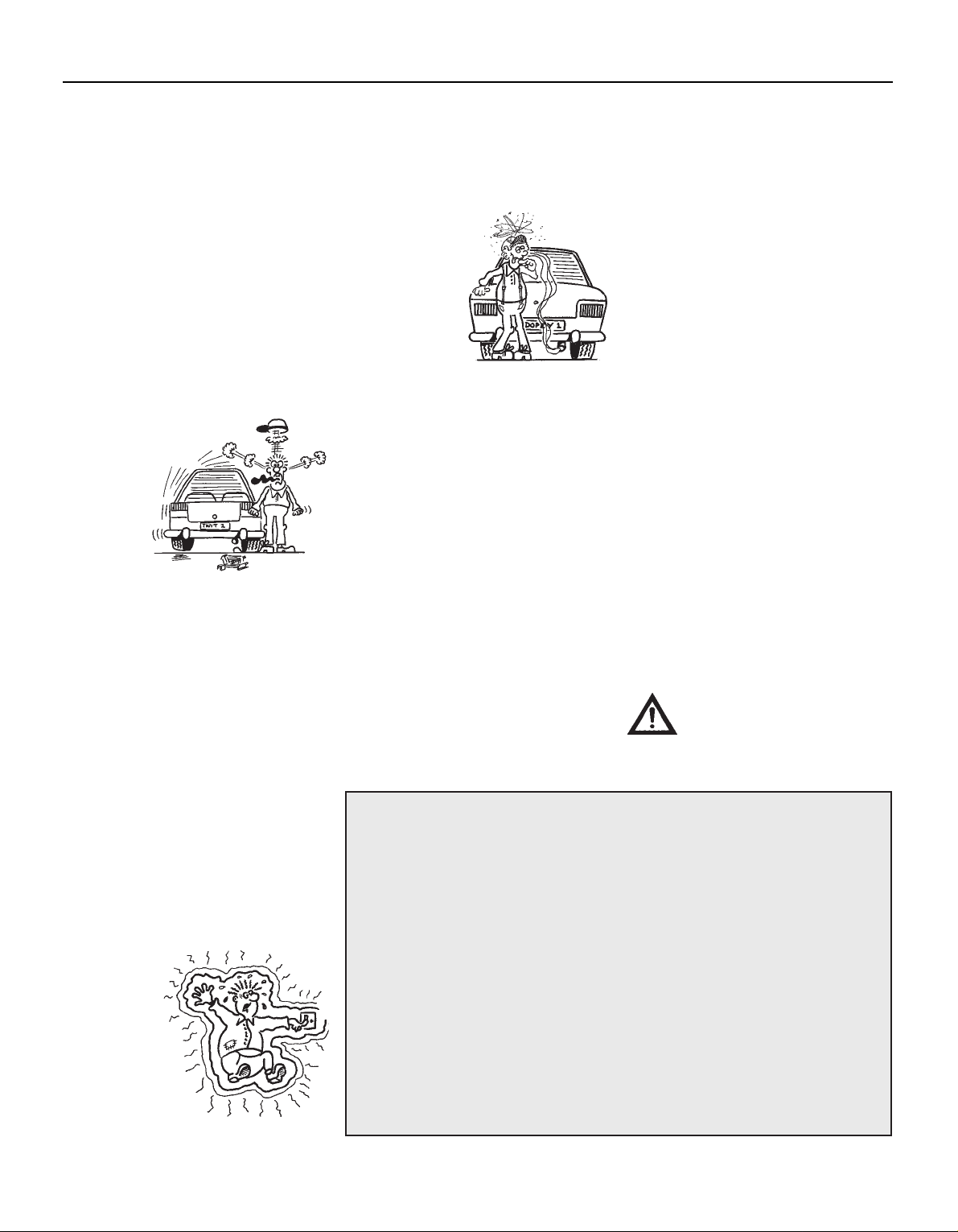
M Is there moisture on electrical components under the
bonnet? Switch off the ignition, then wipe off any obvious
dampness with a dry cloth. Spray a water-repellent aerosol
product (WD-40 or equivalent) on ignition and fuel system
electrical connectors like those shown in the photos.
Pay special attention to the ignition coil wiring connector
and HT leads.
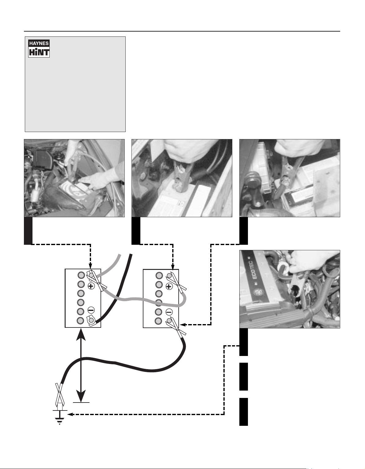
Check the condition and security of the
battery connections
A
Check that the spark plug HT leads are
securely connected by pushing them
onto the plugs (where accessible)
B
Check that the spark plug HT leads are
securely connected by pushing them
onto the DIS module (where accessible)
C
Check that the engine management
system wiring connectors are securely
connected
D
Check that electrical connections are secure (with the ignition switched off) and spray them
with a water dispersant spray like WD40 if you suspect a problem due to damp
Page 8
Roadside repairs 0•7
3510 Vauxhall/Opel Omega
Jump starting will get you out
of trouble, but you must correct
whatever made the battery go
flat in the first place. There are
three possibilities:
1
The battery has been drained by
repeated attempts to start, or by
leaving the lights on.
2
The charging system is not working
properly (alternator drivebelt slack
or broken, alternator wiring fault or
alternator itself faulty).
3
The battery itself is at fault
(electrolyte low, or battery worn out).
Connect one end of the red jump lead to
the positive (+) terminal of the flat
battery
Connect the other end of the red lead to
the positive (+) terminal of the booster
battery.
Connect one end of the black jump lead
to the negative (-) terminal of the booster
battery
Connect the other end of the black jump
lead to a bolt or bracket on the engine
block, well away from the battery, on the
vehicle to be started.
1 2 3
4
Make sure that the jump leads will not
come into contact with the fan, drivebelts or other moving parts of the
engine.
5
Start the engine using the booster
battery and run it at idle speed. Switch
on the lights, rear window demister and
heater blower motor, then disconnect
the jump leads in the reverse order of
connection. Turn off the lights etc.
6
When jump-starting a car using a
booster battery, observe the following
precautions:
4 Before connecting the booster
battery, make sure that the ignition is
switched off.
4 Ensure that all electrical equipment
(lights, heater, wipers, etc) is
switched off.
4 Take note of any special precautions
printed on the battery case.
4 Make sure that the booster battery is
the same voltage as the discharged
one in the vehicle.
4 If the battery is being jump-started
from the battery in another vehicle,
the two vehicles MUST NOT TOUCH
each other.
4 Make sure that the transmission is in
neutral (or PARK, in the case of
automatic transmission).
Jump starting
Page 9
0•8 Roadside repairs
3510 Vauxhall/Opel Omega
Wheel changing
Some of the details shown here will vary
according to model.
Warning: Do not change a wheel in a situation where you risk being hit by
another vehicle. On busy roads, try to stop in a lay-by or a gateway. Be wary of
passing traffic while changing the wheel - it is easy to become distracted by
the job in hand.
Preparation
M When a puncture occurs, stop as soon as
it is safe to do so.
M Park on firm level ground, if possible,
and well out of the way of other traffic.
M Use hazard warning lights if necessary.
M If you have one, use a warning triangle to
alert other drivers of your presence.
M Apply the handbrake and engage first or
reverse gear (or Park on models with
automatic transmission.
M Chock the wheel diagonally opposite the
one being removed – a couple of large
stones will do for this.
M If the ground is soft, use a flat piece of
wood to spread the load under the jack.
Changing the wheel
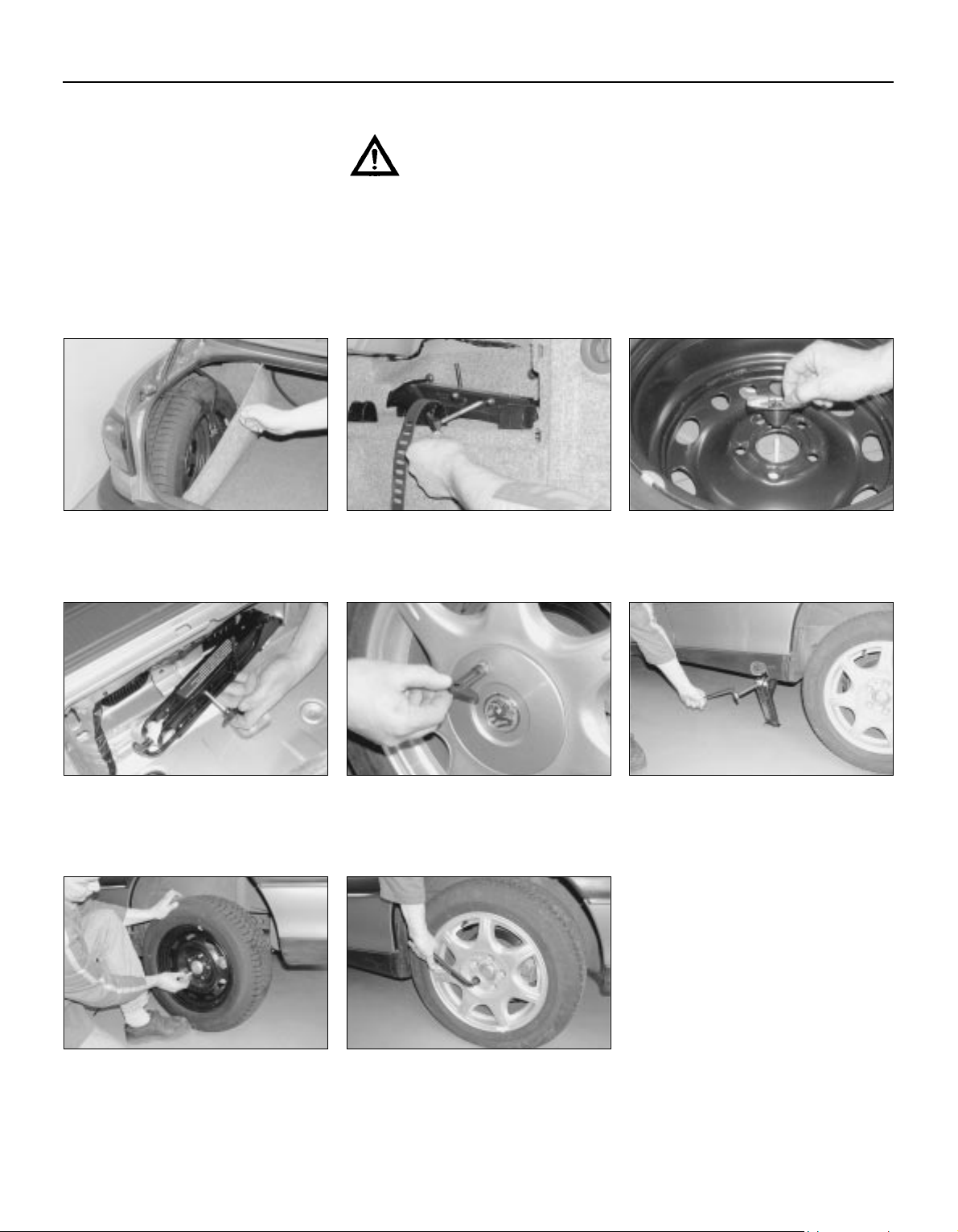
On Saloon models unclip the luggage
compartment left-hand trim panel then
release the retaining strap and remove
the spare wheel . . .
On Estate models lift up the luggage
compartment floor panel and remove the
tools from the centre of the spare wheel.
Undo the retaining nut and remove the spare
wheel . . .
. . . The tools and jack are stored in the
smaller compartment on the right-hand
side of the luggage compartment. Remove
the cover (where fitted) then unscrew the bolt
and remove the jack and wheelbrace.
1 2 3
. . . then unscrew the retaining bolt and
remove the jack from behind the wheel.
On models with steel wheels, use the
removal tool supplied to pull off the wheel
trim and on models with alloy wheels, use
the tool supplied to unscrew the anti-theft bolt
and remove the hub cap. Slacken each wheel
bolt by half a turn.
Unclip the access cover from the sill trim
panel then make sure the jack is located
on firm ground and engage the jack head
correctly with the lifting point on the sill. Make
sure that the lug on the jack head is correctly
located in the sill seam cutout and the base of
the jack is directly underneath the sill seam.
4 5
Raise the jack until the wheel is raised
clear of the ground. Unscrew the wheel
bolts and remove the wheel. Fit the spare
wheel and screw on the bolts. Lightly tighten
the bolts with the wheelbrace then lower the
vehicle to the ground.
Securely tighten the wheel bolts in a
diagonal sequence then refit the hub
cap/wheel trim (as applicable). Note that
the wheel bolts should be slackened and
retightened to the specified torque at the
earliest possible opportunity.
7 8
6
Finally...
M Remove the wheel chocks.
M Stow the punctured wheel, jack and tools
in the correct locations in the car.
M
Check the tyre pressure on the wheel just
fitted. If it is low, or if you don’t have a
pressure gauge with you, drive slowly to
the nearest garage and inflate the tyre to
the right pressure.
M Have the damaged tyre or wheel repaired
as soon as possible.
Page 10
Roadside repairs 0•9
3510 Vauxhall/Opel Omega
Puddles on the garage floor or drive, or
obvious wetness under the bonnet or
underneath the car, suggest a leak that needs
investigating. It can sometimes be difficult to
decide where the leak is coming from,
especially if the engine bay is very dirty
already. Leaking oil or fluid can also be blown
rearwards by the passage of air under the car,
giving a false impression of where the
problem lies.
Warning: Most automotive oils
and fluids are poisonous. Wash
them off skin, and change out
of contaminated clothing,
without delay.
Identifying leaks
The smell of a fluid leaking
from the car may provide a
clue to what’s leaking. Some
fluids are distictively coloured.
It may help to clean the car carefully
and to park it over some clean paper
overnight as an aid to locating the
source of the leak.
Remember that some leaks may only
occur while the engine is running.
Sump oil Gearbox oil
Brake fluid Power steering fluid
Oil from filter
Antifreeze
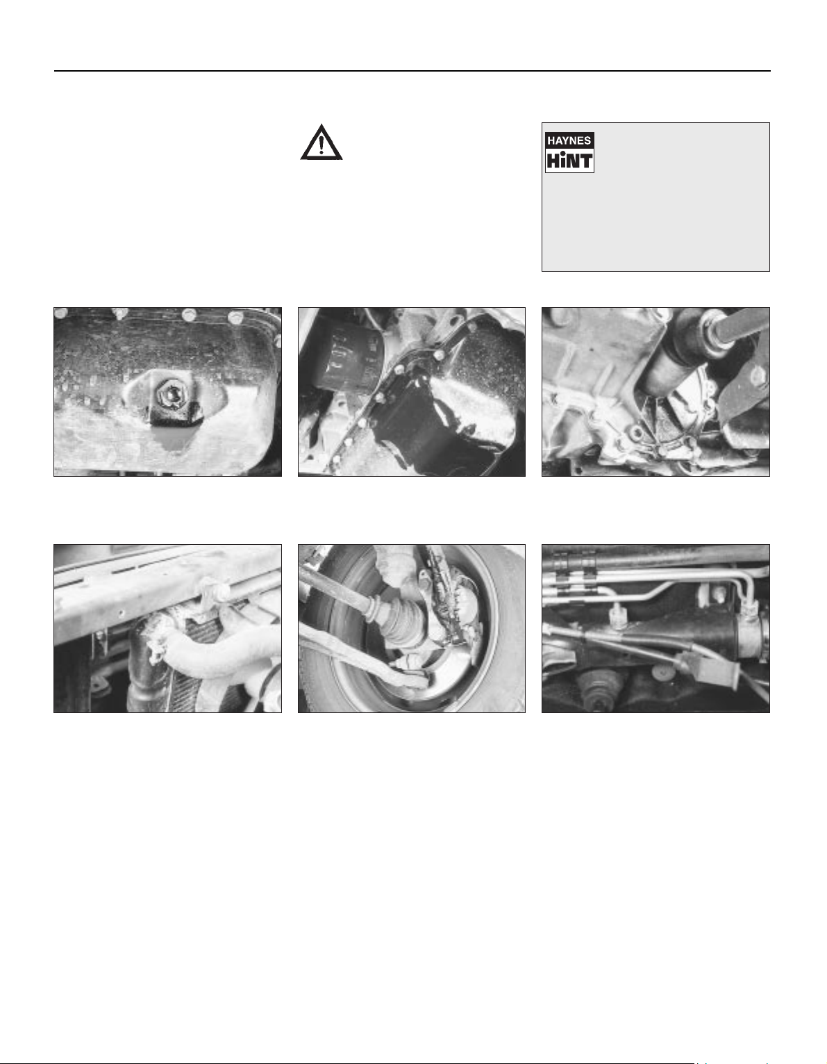
Engine oil may leak from the drain plug... ...or from the base of the oil filter.
Leaking antifreeze often leaves a crystalline
deposit like this.
Gearbox oil can leak from the seals at the
inboard ends of the driveshafts.
A leak occurring at a wheel is almost
certainly brake fluid.
Power steering fluid may leak from the pipe
connectors on the steering rack.
When all else fails, you may find yourself
having to get a tow home – or of course you
may be helping somebody else. Long-distance
recovery should only be done by a garage or
breakdown service. For shorter distances, DIY
towing using another car is easy enough, but
observe the following points:
M Use a proper tow-rope – they are not
expensive. The vehicle being towed must
display an ‘ON TOW’ sign in its rear window.
M Always turn the ignition key to the ‘on’
position when the vehicle is being towed, so
that the steering lock is released, and that the
direction indicator and brake lights will work.
M Both front and rear towing eyes are
provided. They are located behind the access
covers on the front and rear bumper.
M Before being towed, release the handbrake
and select neutral on the transmission.
M Note that greater-than-usual pedal
pressure will be required to operate the
brakes, since the vacuum servo unit is only
operational with the engine running.
M On models with power steering, greater-
than-usual steering effort will also be required.
M The driver of the car being towed must
keep the tow-rope taut at all times to avoid
snatching.
M Make sure that both drivers know the route
before setting off.
M Only drive at moderate speeds and keep
the distance towed to a minimum. Drive
smoothly and allow plenty of time for slowing
down at junctions.
M On models with automatic transmission,
special precautions apply. If in doubt, do not
tow, or transmission damage may result.
Towing
Page 11
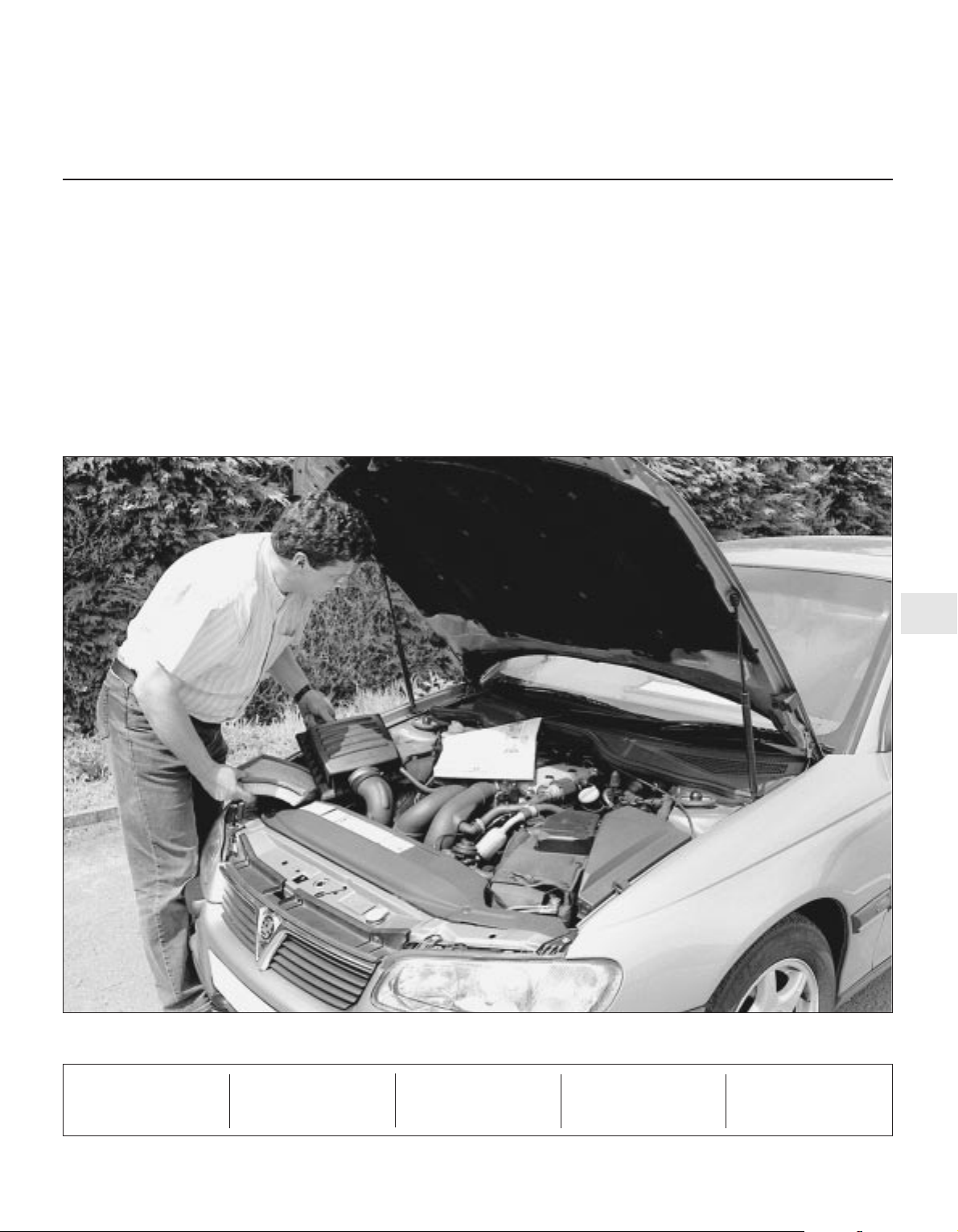
0•10 Weekly checks
3510 Vauxhall/Opel Omega
There are some very simple checks which
need only take a few minutes to carry out, but
which could save you a lot of inconvenience
and expense.
These "Weekly checks" require no great skill
or special tools, and the small amount of time
they take to perform could prove to be very
well spent, for example;
M Keeping an eye on tyre condition and
pressures, will not only help to stop them
wearing out prematurely, but could also save
your life.
M
Many breakdowns are caused by electrical
problems. Battery-related faults are particularly
common, and a quick check on a regular basis
will often prevent the majority of
these.
M If your car develops a brake fluid leak, the
first time you might know about it is when
your brakes don't work properly. Checking
the level regularly will give advance warning of
this kind of problem.
M If the oil or coolant levels run low, the cost
of repairing any engine damage will be far
greater than fixing the leak, for example.
Introduction
§
2.0 litre DOHC
engine
A
Engine oil level dipstick
B
Engine oil filler cap
C
Coolant expansion tank
D
Brake (and clutch) fluid
reservoir
E
Battery
F
Power steering fluid reservoir
Underbonnet check points
§
2.5 and
3.0 litre engine
A
Engine oil level dipstick
B
Engine oil filler cap
C
Coolant expansion tank
D
Brake (and clutch) fluid
reservoir
E
Battery
F
Power steering fluid reservoir
G
Screen washer fluid reservoir
Page 12
Weekly checks 0•11
3510 Vauxhall/Opel Omega
Engine oil level
Before you start
4 Make sure that your car is on level ground.
4 Check the oil level before the car is driven,
or at least 5 minutes after the engine has been
switched off.
The correct oil
Modern engines place great demands on their
oil. It is very important that the correct oil for
your car is used (See “Lubricants and fluids”
on page 0•16).
Car Care
l If you have to add oil frequently, you should
check whether you have any oil leaks. Place
some clean paper under the car overnight,
and check for stains in the morning. If there
are no leaks, the engine may be burning oil
(see “Fault Finding”).
l Always maintain the level between the
upper and lower dipstick marks (see photo 3).
If the level is too low severe engine damage
may occur. Oil seal failure may result if the
engine is overfilled by adding too much oil.
If the oil is checked
immediately after driving the
vehicle, some of the oil will
remain in the upper engine
components, resulting in an inaccurate
reading on the dipstick!
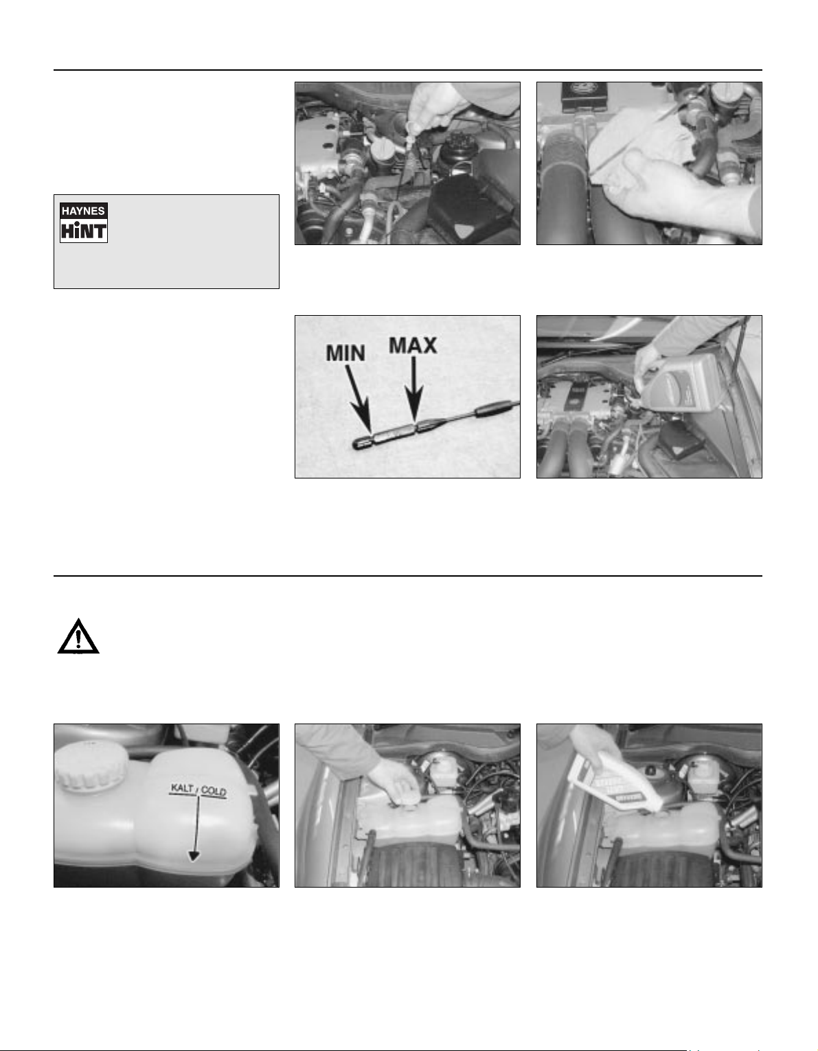
The dipstick is located on the left-hand
side of the engine (see Underbonnet
check points on page 0•10 for exact
location). Withdraw the dipstick.
Using a clean rag or paper towel remove
all oil from the dipstick. Insert the clean
dipstick into the tube as far as it will go,
then withdraw it again.
Note the oil level on the end of the
dipstick, which should be between the
upper (MAX) mark and lower (MIN) mark.
Approximately 1.0 litre of oil will raise the level
from the lower mark to the upper mark.
Oil is added through the filler cap. Rotate
the cap through a quarter-turn anti-
clockwise and withdraw it. Top-up the
level. A funnel may help to reduce spillage.
Add the oil slowly, checking the level on the
dipstick often. Do not overfill.
12
34
Warning: DO NOT attempt to
remove the expansion tank
pressure cap when the engine
is hot, as there is a very great
risk of scalding. Do not leave
open containers of coolant
about, as it is poisonous.
Car Care
l With a sealed-type cooling system, adding
coolant should not be necessary on a regular
basis. If frequent topping-up is required, it is
likely there is a leak. Check the radiator, all
hoses and joint faces for signs of staining or
wetness, and rectify as necessary.
l It is important that antifreeze is used in the
cooling system all year round, not just during
the winter months. Don’t top-up with water
alone, as the antifreeze will become too
diluted.
Coolant level
The coolant level varies with the
temperature of the engine. When the
engine is cold, the coolant level should
be slightly above the KALT/COLD mark on the
side of the tank. When the engine is hot, the
level will rise.
If topping up is necessary, wait until the
engine is cold. Slowly unscrew the
expansion tank cap, to release any
pressure present in the cooling system, and
remove it.
Add a mixture of water and antifreeze to
the expansion tank until the coolant level
is slightly above the KALT/COLD mark
then securely refit the expansion tank cap.
123
Page 13
0•12 Weekly checks
3510 Vauxhall/Opel Omega
Brake and clutch* fluid level
*On manual transmission models the brake fluid reservoir also supplies fluid to the clutch master cylinder.
Warning:
l Brake fluid can harm your
eyes and damage painted
surfaces, so use extreme
caution when handling and
pouring it.
l Do not use fluid that has
been standing open for some
time, as it absorbs moisture
from the air, which can cause a
dangerous loss of braking
effectiveness.
Safety First!
l If the reservoir requires repeated toppingup this is an indication of a fluid leak
somewhere in the system, which should be
investigated immediately.
l If a leak is suspected, the car should not be
driven until the braking system has been
checked. Never take any risks where brakes
are concerned.
• Make sure that your car is
on level ground.
• The fluid level in the
reservoir will drop slightly as
the brake pads wear down, but the fluid
level must never be allowed to drop
below the “MIN” mark.
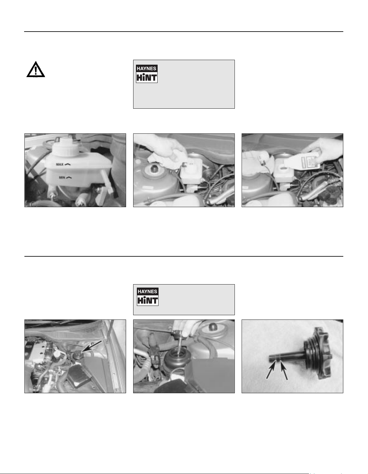
The upper (MAX) and lower (MIN) fluid
level markings are on the side of the
reservoir, which is located in the righthand rear corner of the engine compartment.
The fluid level must always be kept in
between these two marks.
1
If topping-up is necessary, first wipe
clean the area around the filler cap to
prevent dirt entering the hydraulic
system.
2
Carefully add fluid, taking care not to spill
it onto the surrounding components. Use
only the specified fluid; mixing different
types can cause damage to the system. After
topping-up to the correct level, securely refit
the cap and wipe off any spilt fluid.
3
Power steering fluid level
Before you start:
4 Park the vehicle on level ground.
4 Set the steering wheel straight-ahead.
4 The engine should be turned off.
Safety First!
l The need for frequent topping-up indicates
a leak, which should be investigated
immediately.
For the check to be
accurate, the steering must
not be turned once the
engine has been stopped.
The power steering fluid reservoir is
located on the left-hand side of the
engine compartment. Wipe clean the
reservoir before unscrewing and removing the
cap.
1
Wipe clean the filler cap dipstick then
refit the filler cap and remove it again.
Note the fluid level on the dipstick.
2
When the engine is cold the fluid level
should be up to the lower mark up the
dipstick and when the engine is at
operating temperature it should be at the
upper mark. Top up the fluid level using the
specified type of fluid (do not overfill) then
securely refit the filler cap.
3
Page 14
Weekly checks 0•13
3510 Vauxhall/Opel Omega
Battery
Caution: Before carrying out any work on the
vehicle battery, read the precautions given in
"Safety first" at the start of this manual.
4 Make sure that the battery tray is in good
condition, and that the clamp is tight.
Corrosion on the tray, retaining clamp and the
battery itself can be removed with a solution
of water and baking soda. Thoroughly rinse all
cleaned areas with water. Any metal parts
damaged by corrosion should be covered
with a zinc-based primer, then painted.
4 Periodically (approximately every three
months), check the charge condition of the
battery as described in Chapter 5A.
4 If the battery is flat, and you need to jump
start your vehicle, see Roadside Repairs.
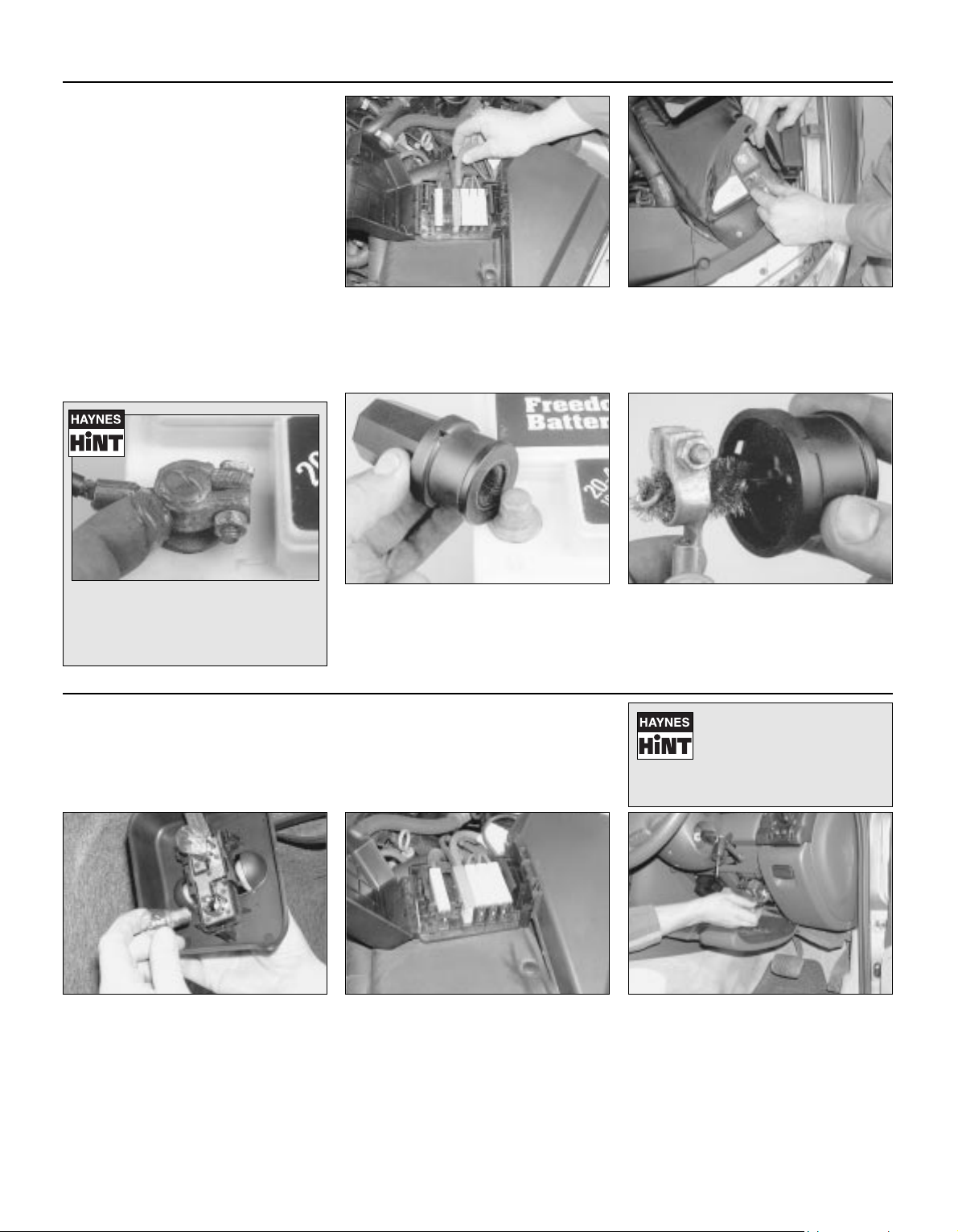
The battery is located at the front lefthand corner of the engine compartment.
If necessary, unclip the fusible link
housing (where fitted) from side of the relay
box then open up the insulating cover to gain
access to the battery.
1
The exterior of the battery should be
inspected periodically for damage such
as a cracked case or cover. Check the
battery lead clamps for tightness to ensure
good electrical connections and check the
leads for signs of damage.
2
Battery corrosion can be kept to a
minimum by applying a layer of
petroleum jelly to the clamps and
terminals after they are reconnected.
If corrosion (white, fluffy deposits) is
evident, remove the cables from the
battery terminals, clean them with a small
wire brush, then refit them. Automotive stores
sell a tool for cleaning the battery post . . .
3
. . . as well as the battery cable clamps
4
Electrical systems
4 Check all external lights and the horn. Refer
to the appropriate Sections of Chapter 12 for
details if any of the circuits are found to be
inoperative.
4 Visually check all accessible wiring
connectors, harnesses and retaining clips for
security, and for signs of chafing or damage.
If you need to check your
brake lights and indicators
unaided, back up to a wall or
garage door and operate the
lights. The reflected light should show if
they are working properly.
If a single indicator light, stop-light or
headlight has failed, it is likely that a bulb
has blown and will need to be replaced.
Refer to Chapter 12 for details. If both stop
lights have failed, it is possible that the switch
has failed (see Chapter 12, Section 4).
If more than one indicator light or tail light
has failed it is likely that either a fuse has
blown or that there is a fault in the circuit
(see Chapter 12). Most fuses are located behind
in the fusebox, behind the cover on the driver’s
side of the facia; depress the locking button and
remove the cover to gain access. Additional
fuses can be found in the engine compartment
relay box and fusible link housing.
2
To replace a blown fuse, remove it, where
applicable, using the plastic tool
provided. Fit a new fuse of the same
rating, available from car accessory shops. It
is important that you find the reason that the
fuse blew (see Electrical fault finding in
Chapter 12).
31
Page 15
0•14 Weekly checks
3510 Vauxhall/Opel Omega
Tyre condition and pressure
It is very important that tyres are in good
condition, and at the correct pressure - having
a tyre failure at any speed is highly dangerous.
Tyre wear is influenced by driving style - harsh
braking and acceleration, or fast cornering,
will all produce more rapid tyre wear. As a
general rule, the front tyres wear out faster
than the rears. Interchanging the tyres from
front to rear ("rotating" the tyres) may result in
more even wear. However, if this is
completely effective, you may have the
expense of replacing all four tyres at once!
Remove any nails or stones embedded in the
tread before they penetrate the tyre to cause
deflation. If removal of a nail does reveal that
the tyre has been punctured, refit the nail so
that its point of penetration is marked. Then
immediately change the wheel, and have the
tyre repaired by a tyre dealer.
Regularly check the tyres for damage in the
form of cuts or bulges, especially in the
sidewalls. Periodically remove the wheels,
and clean any dirt or mud from the inside and
outside surfaces. Examine the wheel rims for
signs of rusting, corrosion or other damage.
Light alloy wheels are easily damaged by
"kerbing" whilst parking; steel wheels may
also become dented or buckled. A new wheel
is very often the only way to overcome severe
damage.
New tyres should be balanced when they are
fitted, but it may become necessary to rebalance them as they wear, or if the balance
weights fitted to the wheel rim should fall off.
Unbalanced tyres will wear more quickly, as
will the steering and suspension components.
Wheel imbalance is normally signified by
vibration, particularly at a certain speed
(typically around 50 mph). If this vibration is
felt only through the steering, then it is likely
that just the front wheels need balancing. If,
however, the vibration is felt through the
whole car, the rear wheels could be out of
balance. Wheel balancing should be carried
out by a tyre dealer or garage.
Tread Depth - visual check
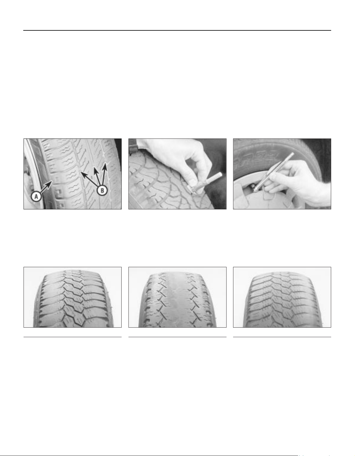
The original tyres have tread wear safety
bands (B), which will appear when the tread
depth reaches approximately 1.6 mm. The
band positions are indicated by a triangular
mark on the tyre sidewall (A).
1
Tread Depth - manual check
Alternatively, tread wear can be
monitored with a simple, inexpensive device
known as a tread depth indicator gauge.
2
Tyre Pressure Check
Check the tyre pressures regularly with
the tyres cold. Do not adjust the tyre
pressures immediately after the vehicle has
been used, or an inaccurate setting will result.
Tyre pressures are shown on page 0•17.
3
Tyre tread wear patterns
Shoulder Wear
Underinflation (wear on both sides)
Under-inflation will cause overheating of the
tyre, because the tyre will flex too much, and
the tread will not sit correctly on the road
surface. This will cause a loss of grip and
excessive wear, not to mention the danger of
sudden tyre failure due to heat build-up.
Check and adjust pressures
Incorrect wheel camber (wear on one side)
Repair or renew suspension parts
Hard cornering
Reduce speed!
Centre Wear
Overinflation
Over-inflation will cause rapid wear of the
centre part of the tyre tread, coupled with
reduced grip, harsher ride, and the danger of
shock damage occurring in the tyre casing.
Check and adjust pressures
If you sometimes have to inflate your car’s
tyres to the higher pressures specified for
maximum load or sustained high speed, don’t
forget to reduce the pressures to normal
afterwards.
Uneven Wear
Front tyres may wear unevenly as a result of
wheel misalignment. Most tyre dealers and
garages can check and adjust the wheel
alignment (or "tracking") for a modest charge.
Incorrect camber or castor
Repair or renew suspension parts
Malfunctioning suspension
Repair or renew suspension parts
Unbalanced wheel
Balance tyres
Incorrect toe setting
Adjust front wheel alignment
Note: The feathered edge of the tread which
typifies toe wear is best checked by feel.
Page 16
Weekly checks 0•15
3510 Vauxhall/Opel Omega
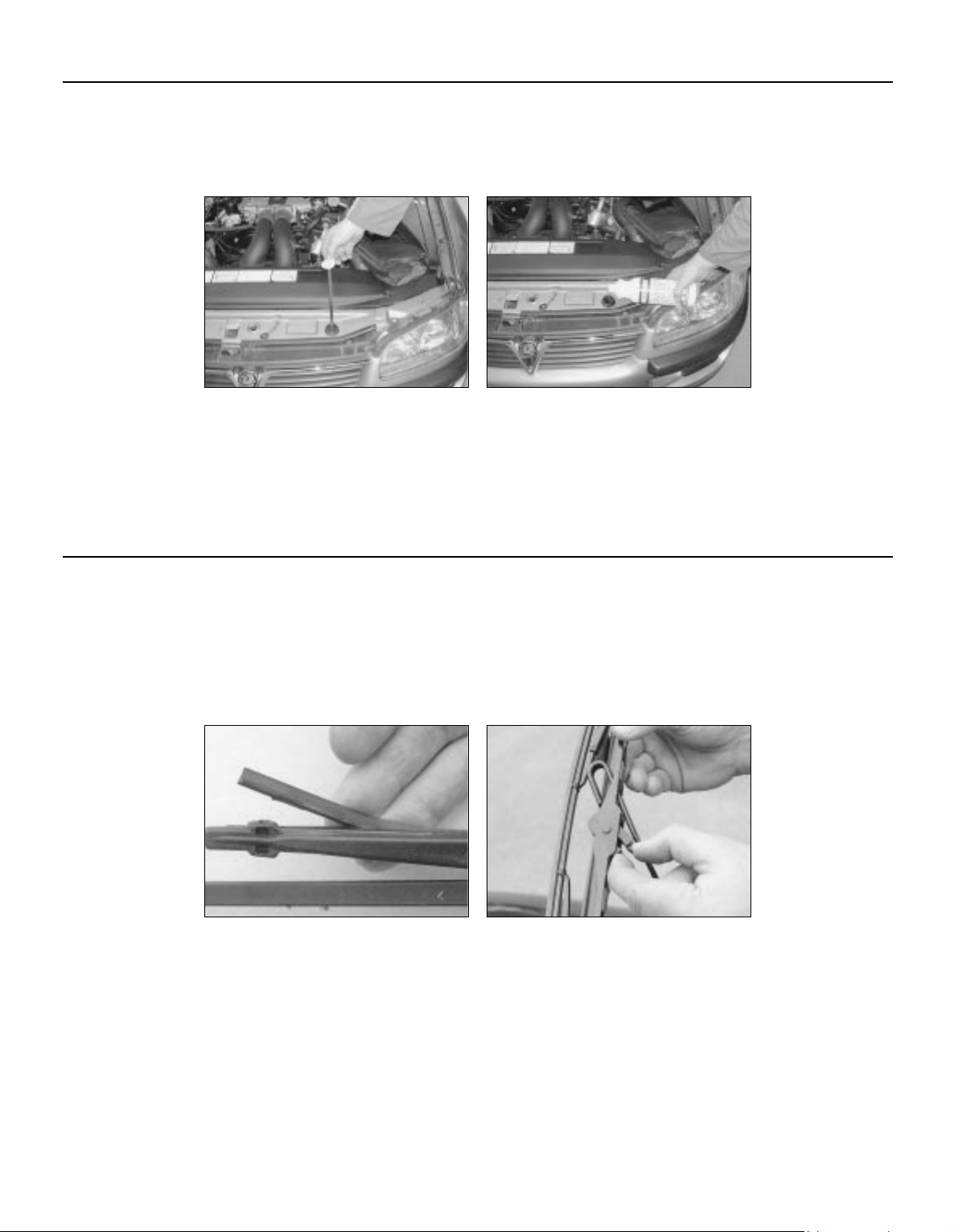
Wiper blades
Check the condition of the wiper blades;
if they are cracked or show any signs of
deterioration, or if the glass swept area is
smeared, renew them. Wiper blades should
be renewed annually.
1
To remove a windscreen wiper blade, pull
the arm fully away from the screen until it
locks. Swivel the blade through 90°,
press the locking tab with your fingers and
slide the blade out of the arm’s hooked end.
2
Screenwash additives not only keep the
winscreen clean during foul weather, they also
prevent the washer system freezing in cold
weather - which is when you are likely to need it
most. Don’t top up using plain water as the
screenwash will become too diluted, and will
freeze during cold weather. On no account use
coolant antifreeze in the washer system this could discolour or damage paintwork.
Washer fluid level
When topping-up the reservoir, a
screenwash additive should be added in
the quantities recommended on the
bottle.
2
The reservoir for the windscreen/
tailgate/headlamps (as applicable) is
located at the front of vehicle. The fluid
level in the reservoir can be checked using the
dipstick attached to the filler cap.
1
Page 17

0•16 Lubricants and fluids
3510 Vauxhall/Opel Omega
Lubricants and fluids
Engine . . . . . . . . . . . . . . . . . . . . . . . . . . . . . . . . . . . . . . . . . . . . Multigrade engine oil, viscosity SAE 10W/40 to 15W/50 to API
SG/CD or SH/CD
(Duckhams QXR Premium Petrol Engine Oil or
Duckhams Hypergrade Petrol Engine Oil)
Cooling system . . . . . . . . . . . . . . . . . . . . . . . . . . . . . . . . . . . . . Ethylene glycol based antifreeze
(Duckhams Antifreeze and Summer Coolant)
Manual transmission:
Early (pre 1999) vehicles:
Up to number JP3097A01361659* . . . . . . . . . . . . . . . . . . . Vauxhall transmission oil 19 40 704
From number JP3097A01361659* . . . . . . . . . . . . . . . . . . . Vauxhall transmission oil 19 40 764
Later (1999 onwards) vehicles . . . . . . . . . . . . . . . . . . . . . . . . Vauxhall transmission oil 19 40 768
Automatic transmission . . . . . . . . . . . . . . . . . . . . . . . . . . . . . . Vauxhall transmission fluid 19 40 763
(Duckhams ATF Autotrans III)
Final drive unit . . . . . . . . . . . . . . . . . . . . . . . . . . . . . . . . . . . . . See Chapter 8 specifications
Braking and clutch system . . . . . . . . . . . . . . . . . . . . . . . . . . . Hydraulic fluid DOT 4
(Duckhams Universal Brake and Clutch Fluid)
Power steering . . . . . . . . . . . . . . . . . . . . . . . . . . . . . . . . . . . . . Vauxhall transmission fluid 19 40 700
(Duckhams ATF Autotrans III)
*The identification number is stamped on the transmission housing. Note: There have been three different types of oil used in the
transmission by Vauxhall. The different types of oil should never be mixed, and it is essential that the transmission is refilled either
with the same type of oil as that drained, or the latest oil used in production from 1999 model year. If it is not known what type of
oil has been drained, the transmission unit should be flushed before filling with the latest specification oil. To do this, refer to
Chapter 7A, Section 2.
Engines need oil, not only to lubricate moving
parts and minimise wear, but also to maximise
power output and to improve fuel economy.
By introducing a simplified and improved
range of engine oils, Duckhams has taken
away the confusion and made it easier for you
to choose the right oil for your engine.
HOW ENGINE OIL WORKS
• Beating friction
Without oil, the moving surfaces inside your
engine will rub together, heat up and melt,
quickly causing the engine to seize. Engine oil
creates a film which separates these moving
parts, preventing wear and heat build-up.
• Cooling hot-spots
Temperatures inside the engine can exceed
1000º C. The engine oil circulates and acts as
a coolant, transferring heat from the hot-spots
to the sump.
• Cleaning the engine internally
Good quality engine oils clean the inside of
your engine, collecting and dispersing
combustion deposits and controlling them
until they are trapped by the oil filter or flushed
out at oil change.
OIL CARE - FOLLOW THE CODE
To handle and dispose of used engine oil
safely, always:
• Avoid skin contact
with used engine oil.
Repeated or prolonged
contact can be harmful.
• Dispose of used oil
and empty packs in a
responsible manner in an
authorised disposal site.
Call 0800 663366 to find
the one nearest to you.
Never tip oil down drains
or onto the ground.
Choosing your engine oil
DUCKHAMS ENGINE OILS
For the driver who demands a premium
quality oil for complete reassurance, we
recommend synthetic formula Duckhams
QXR Premium Engine Oils.
For the driver who requires a straightforward quality engine oil, we recommend
Duckhams Hypergrade Engine Oils.
For further information and advice, call the
Duckhams UK Helpline on 0800 212988.
Page 18

Tyre pressures 0•17
3510 Vauxhall/Opel Omega
Tyre pressures
Note: Pressures apply to original-equipment tyres only and may vary if any other make or type of tyre is fitted; check with the tyre manufacturer or
supplier for correct pressures if necessary.
Note: Tyre pressures must always be checked with the tyres cold to ensure accuracy.
Saloon models
2.0 litre engine Front Rear
Up to 3 passengers (including driver) . . . . . . . . . . . . . . . . . . . . 28.5 psi (2.0 bar) 28.5 psi (2.0 bar)
Fully loaded . . . . . . . . . . . . . . . . . . . . . . . . . . . . . . . . . . . . . . . . 36 psi (2.5 bar) 42 psi (2.9 bar)
2.5 and 3.0 litre engine
Up to 3 passengers (including driver) . . . . . . . . . . . . . . . . . . . . 31.5 psi (2.2 bar) 31.5 psi (2.2 bar)
Fully loaded . . . . . . . . . . . . . . . . . . . . . . . . . . . . . . . . . . . . . . . . 36 psi (2.5 bar) 42 psi (2.9 bar)
Estate models
2.0 litre engine
Up to 3 passengers (including driver) . . . . . . . . . . . . . . . . . . . . 28.5 psi (2.0 bar) 31.5 psi (2.2 bar)
4 or 5 passengers (including driver) and 60 kg of luggage . . . . 33.0 psi (2.3 bar) 45.0 psi (3.1 bar)
Fully loaded . . . . . . . . . . . . . . . . . . . . . . . . . . . . . . . . . . . . . . . . 38.0 psi (2.6 bar) 45.0 psi (3.1 bar)
2.5 and 3.0 litre engine
195/65 R 15 tyres:
Up to 3 passengers (including driver) . . . . . . . . . . . . . . . . . . . 31.5 psi (2.2 bar) 34.0 psi (2.3 bar)
4 or 5 passengers (including driver) and 60 kg of luggage . . . 34.0 psi (2.3 bar) 46.0 psi (3.2 bar)
Fully loaded . . . . . . . . . . . . . . . . . . . . . . . . . . . . . . . . . . . . . . 39.0 psi (2.7 bar) 46.0 psi (3.2 bar)
205/65 R 15 and 225/55 R 15 tyres:
Up to 3 passengers (including driver) . . . . . . . . . . . . . . . . . . . 28.5 psi (2.0 bar) 31.5 psi (2.2 bar)
4 or 5 passengers (including driver) and 60 kg of luggage . . . 33.0 psi (2.3 bar) 45.0 psi (3.1 bar)
Fully loaded . . . . . . . . . . . . . . . . . . . . . . . . . . . . . . . . . . . . . . 38.0 psi (2.6 bar) 45.0 psi (3.1 bar)
Page 19
1•1
1
3510 Vauxhall/Opel Omega
Chapter 1
Routine maintenance and servicing
Air filter element - renewal . . . . . . . . . . . . . . . . . . . . . . . . . . . . . . . . . 16
Automatic transmission fluid - renewal . . . . . . . . . . . . . . . . . . . . . . . 25
Automatic transmission fluid level - check . . . . . . . . . . . . . . . . . . . . 19
Auxiliary drivebelt - check and renewal . . . . . . . . . . . . . . . . . . . . . . . 6
Bodywork/underbody corrosion protection - check . . . . . . . . . . . . . 8
Brake fluid - renewal . . . . . . . . . . . . . . . . . . . . . . . . . . . . . . . . . . . . . 26
Coolant - renewal . . . . . . . . . . . . . . . . . . . . . . . . . . . . . . . . . . . . . . . 28
Driveshaft gaiter condition - check . . . . . . . . . . . . . . . . . . . . . . . . . . 21
Engine oil and filter - renewal . . . . . . . . . . . . . . . . . . . . . . . . . . . . . . 3
Exhaust system - check . . . . . . . . . . . . . . . . . . . . . . . . . . . . . . . . . . 15
Front and rear disc brakes - pad wear check . . . . . . . . . . . . . . . . . . 5
Fuel filter - renewal . . . . . . . . . . . . . . . . . . . . . . . . . . . . . . . . . . . . . . 23
General information . . . . . . . . . . . . . . . . . . . . . . . . . . . . . . . . . . . . . . 1
Handbrake - shoe condition check . . . . . . . . . . . . . . . . . . . . . . . . . . 20
Handbrake operation - check and adjustment . . . . . . . . . . . . . . . . . 9
Headlight and auxiliary driving light beam alignment - check . . . . . . 12
Lock and hinge lubrication . . . . . . . . . . . . . . . . . . . . . . . . . . . . . . . . 18
Monitoring, lighting and signalling equipment - check . . . . . . . . . . . 4
Pollen filter - renewal . . . . . . . . . . . . . . . . . . . . . . . . . . . . . . . . . . . . . 17
Regular maintenance . . . . . . . . . . . . . . . . . . . . . . . . . . . . . . . . . . . . . 2
Remote control keyfob battery - renewal . . . . . . . . . . . . . . . . . . . . . 27
Road test . . . . . . . . . . . . . . . . . . . . . . . . . . . . . . . . . . . . . . . . . . . . . . 13
Spark plugs - renewal . . . . . . . . . . . . . . . . . . . . . . . . . . . . . . . . . . . . 22
Suspension and steering condition and operation - check . . . . . . . . 10
Timing belt - renewal . . . . . . . . . . . . . . . . . . . . . . . . . . . . . . . . . . . . . 24
Underbonnet/underbody hose and fluid leak - check . . . . . . . . . . . . 7
Wheel alignment - check . . . . . . . . . . . . . . . . . . . . . . . . . . . . . . . . . . 14
Wheel bolt torque - check and adjustment . . . . . . . . . . . . . . . . . . . . 11
Contents
Easy, suitable for
novice with little
experience
Fairly easy, suitable
for beginner with
some experience
Fairly difficult,
suitable for competent
DIY mechanic
Difficult, suitable for
experienced DIY
mechanic
Very difficult,
suitable for expert DIY
or professional
Degrees of difficulty
5
4
3
2
1
Page 20

Lubricants and fluids . . . . . . . . . . . . . . . . . . . . . . . . . . . . . . . . . . Refer to end of Weekly checks on page 0•16
Capacities
Engine oil
2.0 litre engine:
SOHC engine . . . . . . . . . . . . . . . . . . . . . . . . . . . . . . . . . . . . . . . . . 4.5 litres
DOHC engine:
Engines with a one-piece sump . . . . . . . . . . . . . . . . . . . . . . . . . 4.5 litres
Engines with a two-piece sump . . . . . . . . . . . . . . . . . . . . . . . . . 5.0 litres
2.5 and 3.0 litre engine . . . . . . . . . . . . . . . . . . . . . . . . . . . . . . . . . . . . 5.75 litres
Difference between MIN and MAX on dipstick (all engines) . . . . . . . . . . 1.0 litre
Cooling system Manual transmission Automatic transmission
2.0 litre engine:
SOHC engine . . . . . . . . . . . . . . . . . . . . . . . . . . . . . . . . . . . . . . . . . . . 9.0 litres 8.8 litres
DOHC engine . . . . . . . . . . . . . . . . . . . . . . . . . . . . . . . . . . . . . . . . . . . 8.8 litres 8.6 litres
2.5 and 3.0 litre engine . . . . . . . . . . . . . . . . . . . . . . . . . . . . . . . . . . . . . . 9.7 litres 9.5 litres
Transmission
Manual transmission (approximate) . . . . . . . . . . . . . . . . . . . . . . . . . . . . 1.2 litres
Automatic transmission (approximate):
From dry . . . . . . . . . . . . . . . . . . . . . . . . . . . . . . . . . . . . . . . . . . . . . . . 8.4 litres
After removing main sump . . . . . . . . . . . . . . . . . . . . . . . . . . . . . . . . . 4.4 litres
Final drive . . . . . . . . . . . . . . . . . . . . . . . . . . . . . . . . . . . . . . . . . . . . . . . . 1.0 litre*
*On models with limited-slip differential, observe the notes in Chapter 8 regarding the correct mixture of oil and additive to be used when refilling
the final drive unit.
Washer fluid reservoir
Without headlight washers . . . . . . . . . . . . . . . . . . . . . . . . . . . . . . . . . . . 3.0 litres
With headlight washers . . . . . . . . . . . . . . . . . . . . . . . . . . . . . . . . . . . . . 6.4 litres
Fuel tank
All models . . . . . . . . . . . . . . . . . . . . . . . . . . . . . . . . . . . . . . . . . . . . . . . . 75 litres
Engine
Oil filter . . . . . . . . . . . . . . . . . . . . . . . . . . . . . . . . . . . . . . . . . . . . . . . . . . Champion G102
Cooling system
Antifreeze mixture:
50% antifreeze . . . . . . . . . . . . . . . . . . . . . . . . . . . . . . . . . . . . . . . . . . Protection down to -37ºC
55% antifreeze . . . . . . . . . . . . . . . . . . . . . . . . . . . . . . . . . . . . . . . . . . Protection down to -45ºC
Note: Refer to antifreeze manufacturer for latest recommendations.
Fuel system
Air filter element:
2.0 litre engine . . . . . . . . . . . . . . . . . . . . . . . . . . . . . . . . . . . . . . . . . . Champion U595
2.5 and 3.0 litre engine . . . . . . . . . . . . . . . . . . . . . . . . . . . . . . . . . . . . Champion U601
Fuel filter . . . . . . . . . . . . . . . . . . . . . . . . . . . . . . . . . . . . . . . . . . . . . . . . . Champion L225
Ignition system
Spark plugs (gap not adjustable - see text) . . . . . . . . . . . . . . . . . . . . . . Champion RC10DMC
Brakes
Friction material minimum thickness:
Front brake pads . . . . . . . . . . . . . . . . . . . . . . . . . . . . . . . . . . . . . . . . . 8.0 mm including backing plate
Rear brake pads . . . . . . . . . . . . . . . . . . . . . . . . . . . . . . . . . . . . . . . . . 6.0 mm including backing plate
Handbrake shoes . . . . . . . . . . . . . . . . . . . . . . . . . . . . . . . . . . . . . . . . 1.0 mm excluding backing plate
Torque wrench settings Nm lbf ft
Automatic transmission fluid level plug . . . . . . . . . . . . . . . . . . . . . . . . . 33 24
Oil filter . . . . . . . . . . . . . . . . . . . . . . . . . . . . . . . . . . . . . . . . . . . . . . . . . . 15 11
Roadwheel bolts . . . . . . . . . . . . . . . . . . . . . . . . . . . . . . . . . . . . . . . . . . . 110 81
Spark plugs . . . . . . . . . . . . . . . . . . . . . . . . . . . . . . . . . . . . . . . . . . . . . . . 25 18
Sump drain plug:
2.0 litre SOHC engine . . . . . . . . . . . . . . . . . . . . . . . . . . . . . . . . . . . . . 55 41
2.0 litre DOHC engine:
Hex-head bolt . . . . . . . . . . . . . . . . . . . . . . . . . . . . . . . . . . . . . . . . . 45 33
Torx-head bolt . . . . . . . . . . . . . . . . . . . . . . . . . . . . . . . . . . . . . . . . . 10 7
2.5 and 3.0 litre engine:
Hex-head bolt . . . . . . . . . . . . . . . . . . . . . . . . . . . . . . . . . . . . . . . . . 55 41
Torx-head bolt . . . . . . . . . . . . . . . . . . . . . . . . . . . . . . . . . . . . . . . . . 10 7
1•2 Servicing specifications
3510 Vauxhall/Opel Omega
Page 21

The maintenance intervals in this manual
are provided with the assumption that you,
not the dealer, will be carrying out the work.
These are the minimum maintenance intervals
recommended by us for vehicles driven daily.
If you wish to keep your vehicle in peak
condition at all times, you may wish to
perform some of these procedures more
often. We encourage frequent maintenance,
because it enhances the efficiency,
performance and resale value of your vehicle.
If the vehicle is driven in dusty areas, used
to tow a trailer, or driven frequently at slow
speeds (idling in traffic) or on short journeys,
more frequent maintenance intervals are
recommended.
When the vehicle is new, and/or still within
its warranty period, it should be serviced by a
factory-authorised dealer service department,
in order to preserve the factory warranty.
Maintenance schedule 1•3
1
3510 Vauxhall/Opel Omega
Every 5000 miles (7500 km) or
6 months, whichever comes first
mm Engine oil and filter - renewal (Section 3)
Note: Vauxhall recommend that the engine oil and filter are changed
every 10 000 miles or 12 months. However, oil and filter changes are
good for the engine and we recommend that the oil and filter are
renewed more frequently, especially if the vehicle is used on a lot of
short journeys.
Every 40 000 miles (60 000 km) or
4 years, whichever comes first
Carry out all the operations listed for the 15,000 km/12 month and the
30,000 km/2 year intervals, plus the following additional operations:
mm Spark plugs - renewal (Section 22)*
mm Fuel filter - renewal (Section 23)
mm Timing belt - renewal (Section 24)**
* Note: On pre-1999 model year vehicles, renew the spark plugs
every 40 000 miles (60 000 km) regardless of the time elapsed.
**Note: Since the introduction of the Omega in 1994, Vauxhall have
gradually increased the specified interval for timing belt renewal as
follows:
1994 model year vehicle,
36 000 miles or 4 years, whichever comes first.
1995 and 1996 model year vehicles,
40 000 miles or 4 years, whichever comes first.
1997 model year vehicles onwards,
80 000 miles or 8 years, whichever comes first.
However, if the vehicle is used mainly for short journeys or a lot of
stop-start driving, or if the vehicle’s history is unknown, it is
recommended that the earlier (1994 model year) recommendation is
adhered to. The actual belt renewal interval is very much up to the
individual owner but, bearing in mind that severe engine damage will
result if the belt breaks in use, we recommend you err on the side of
caution.
Every 10 000 miles (15 000 km) or
12 months, whichever comes first
mm Monitoring, lighting and signalling equipment -
check (Section 4)
mm Front and rear brakes - pad and disc wear check
(Section 5)
mm Auxiliary drivebelt condition and tension - check
and adjust (Section 6)*
mm Underbonnet/underbody hose and fluid leak -
check (Section 7)*
mm Bodywork/underbody corrosion protection - check
(Section 8)*
mm Handbrake operation - check and adjustment
(Section 9)*
mm Suspension and steering condition and operation -
check (Section 10)*
mm Wheel bolt torque - check and adjustment
(Section 11)
mm Headlight and auxiliary driving light beam
alignment - check (Section 12)*
mm Road test (Section 13)
mm Wheel alignment - check (Section 14)
mm Exhaust system - check (Section 15)*
* Note: On vehicles covering a high mileage (more than 20 000
miles/30 000 km annually) carry out the items marked with an asterisk
at the 12 month interval; carry out the items not marked with an
asterisk every 10 000 miles/15 000 km, regardless of elapsed time.
Every 70 000 miles (105 000 km) or
7 years whichever comes first
mm Automatic transmission fluid - renewal (Section 25)*
Note: This operation applies only to vehicles covering a high mileage
(more than 20 000 miles/30 000 km annually)
Every 20 000 miles (30 000 km) or
2 years, whichever comes first
Carry out all the operations listed for the 15,000 km/12 month
interval, plus the following additional operations:
mm Air filter element - renewal (Section 16)
mm Pollen filter - renewal (Section 17)
mm Lock and hinge lubrication (Section 18)
mm Automatic transmission fluid level check (Section 19)
mm Handbrake - shoe condition check (Section 20)
mm Driveshaft gaiter condition - check (Section 21)
Every 2 years, regardless of mileage
mm Brake fluid - renewal (Section 26)
mm Remote control keyfob battery - renewal
(Section 27)
mm Coolant - renewal (Section 28)
Page 22
1•4 Maintenance - component location
3510 Vauxhall/Opel Omega
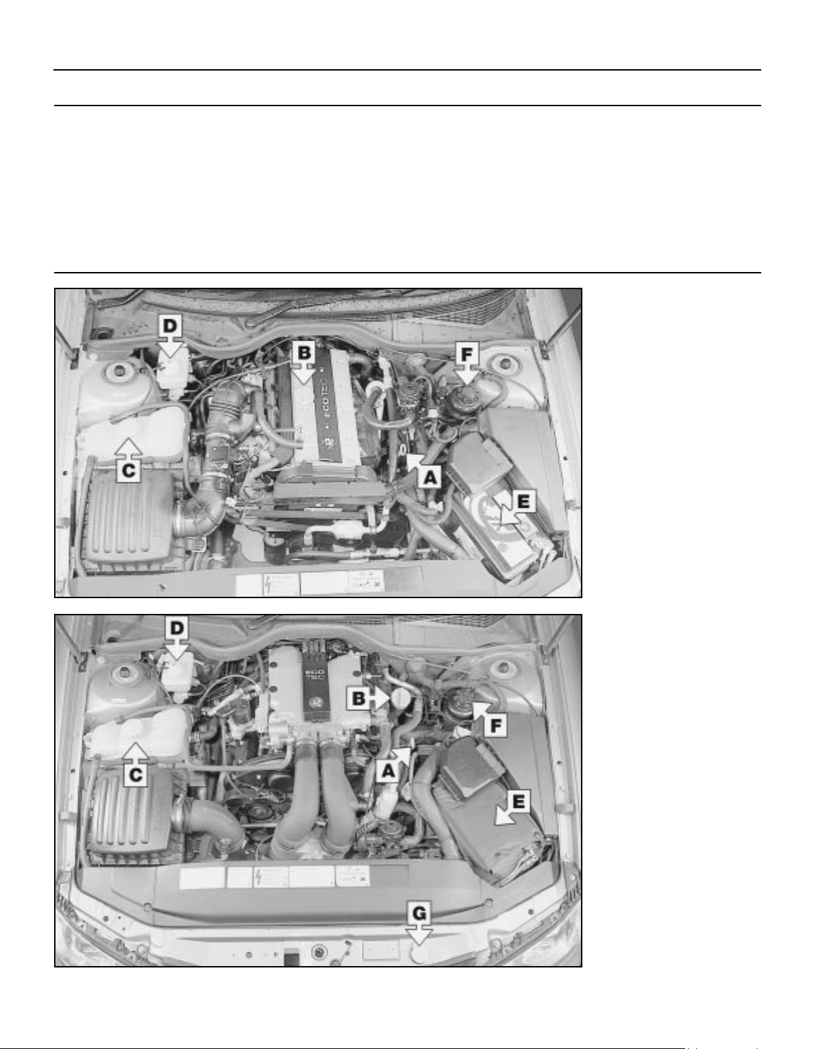
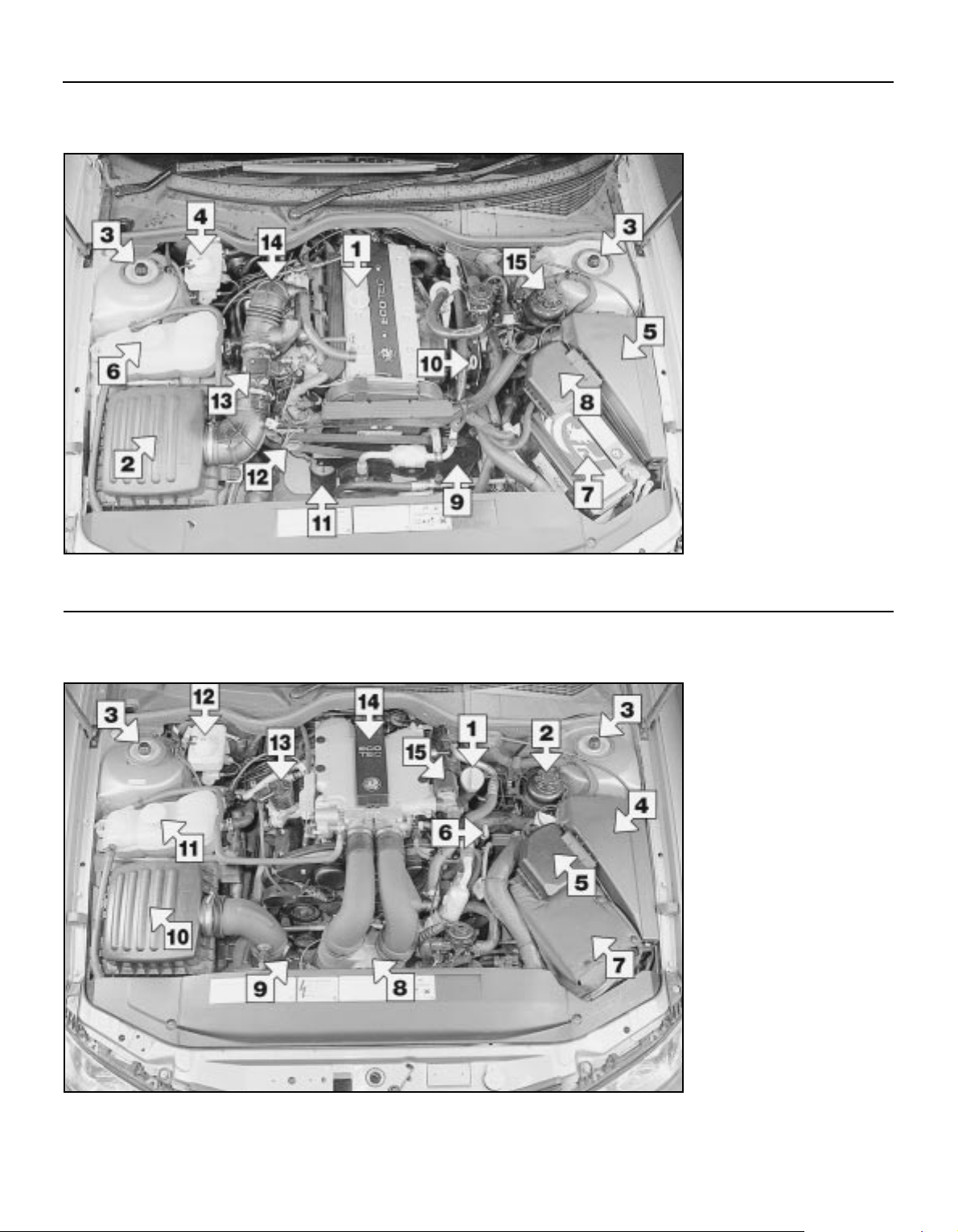
Underbonnet view of a 2.0 litre DOHC engine model
1 Engine oil filler cap
2 Air cleaner
3 Front suspension strut
upper mounting
4 Brake (and clutch) fluid
reservoir
5 Relay box
6 Cooling system expansion
tank
7 Battery
8 Fusible link housing
9 Power steering pump
10 Engine oil level dipstick
11 Oil filter
12 Alternator
13 Airflow meter
14 Throttle housing
15 Power steering fluid
reservoir
Underbonnet view of a 2.5 litre engine model (3.0 litre engine similar)
1 Engine oil filler cap
2 Power steering fluid
reservoir
3 Front suspension strut
upper mounting
4 Relay box
5 Fusible link housing
6 Engine oil level dipstick
7 Battery
8 Multi-ram air intake system
pre-volume chamber
9 Airflow meter
10 Air cleaner
11 Cooling system expansion
tank
12 Brake (and clutch) fluid
reservoir
13 Exhaust gas recirculation
(EGR) valve
14 Inlet manifold
15 Idle speed adjuster valve
Page 23
Maintenance - component location 1•5
1
3510 Vauxhall/Opel Omega
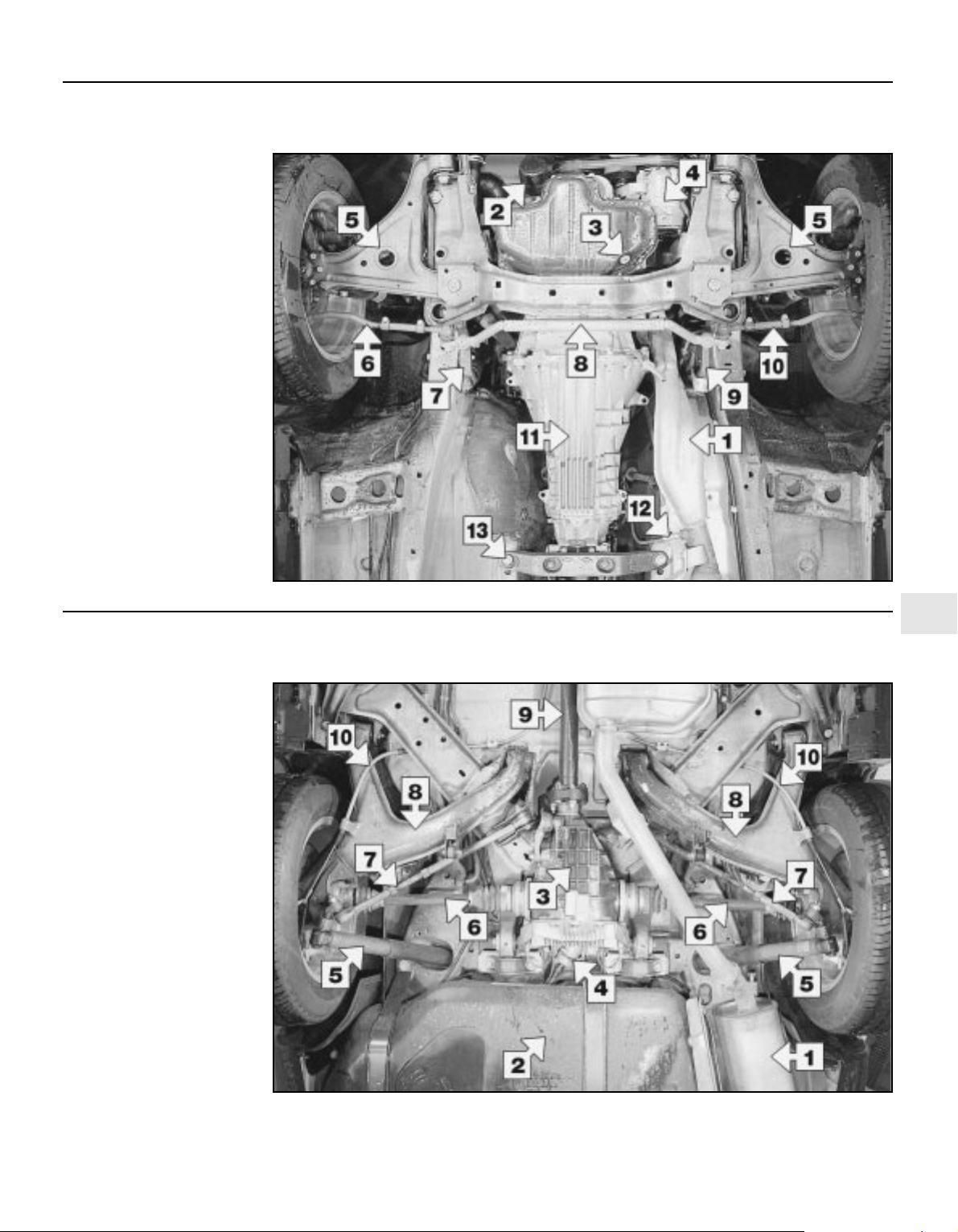
Front underbody view (2.0 litre DOHC engine shown - others similar)
1 Exhaust front downpipe
2 Oil filter
3 Engine oil drain plug
4 Air conditioning system
compressor
5 Front suspension lower
arm
6 Steering outer tie rod
7 Steering drop arm
8 Steering centre tie rod
9 Steering idler
10 Steering outer tie rod
11 Manual transmission
12 Oxygen sensor
13 Transmission unit rear
mounting crossmember
Rear underbody view (2.0 litre DOHC engine shown - others similar)
1 Exhaust tailpipe
2 Fuel tank
3 Final drive unit
4 Fuel filter
5 Rear shock absorber
6 Driveshaft
7 Rear suspension tie rod
8 Rear suspension lower
arm
9 Propeller shaft
10 Handbrake cable
Page 24
1 General information
1 This Chapter is designed to help the home
mechanic maintain his/her vehicle for safety,
economy, long life and peak performance.
2 The Chapter contains a master
maintenance schedule, followed by Sections
dealing specifically with each task in the
schedule. Visual checks, adjustments,
component renewal and other helpful items
are included. Refer to the accompanying
illustrations of the engine compartment and
the underside of the vehicle for the locations
of the various components.
3 Servicing your vehicle in accordance with the
mileage/time maintenance schedule and the
following Sections will provide a planned
maintenance programme, which should result
in a long and reliable service life. This is a
comprehensive plan, so maintaining some
items but not others at the specified service
intervals, will not produce the same results.
4 As you service your vehicle, you will
discover that many of the procedures can and should - be grouped together, because of
the particular procedure being performed, or
because of the proximity of two otherwiseunrelated components to one another. For
example, if the vehicle is raised for any reason,
the exhaust can be inspected at the same time
as the suspension and steering components.
5 The first step in this maintenance pro-
gramme is to prepare yourself before the actual
work begins. Read through all the Sections
relevant to the work to be carried out, then
make a list and gather all the parts and tools
required. If a problem is encountered, seek
advice from a parts specialist, or a dealer
service department.
2 Regular maintenance
1 If, from the time the vehicle is new, the
routine maintenance schedule is followed
closely, and frequent checks are made of fluid
levels and high-wear items, as suggested
throughout this manual, the engine will be
kept in relatively good running condition, and
the need for additional work will be minimised.
2 It is possible that there will be times when
the engine is running poorly due to the lack of
regular maintenance. This is even more likely
if a used vehicle, which has not received
regular and frequent maintenance checks, is
purchased. In such cases, additional work
may need to be carried out, outside of the
regular maintenance intervals.
3 If engine wear is suspected, a compression
test (refer to Chapter 2A, 2B or 2C, as
applicable) will provide valuable information
regarding the overall performance of the main
internal components. Such a test can be used
as a basis to decide on the extent of the work
to be carried out. If, for example, a
compression test indicates serious internal
engine wear, conventional maintenance as
described in this Chapter will not greatly
improve the performance of the engine, and
may prove a waste of time and money, unless
extensive overhaul work is carried out first.
4 The following series of operations are those
most often required to improve the performance of a generally poor-running engine:
Primary operations
a) Clean, inspect and test the battery (refer
to Weekly checks).
b) Check all the engine-related fluids (refer
to Weekly checks).
c) Check the condition and tension of the
auxiliary drivebelt (Section 6).
d) Renew the spark plugs (Section 22).
e) Check the condition of the air filter, and
renew if necessary (Section 16).
f) Renew the fuel filter (Section 23).
g) Check the condition of all hoses, and
check for fluid leak.
5 If the above operations do not prove fully
effective, carry out the following secondary
operations:
Secondary operations
All items listed under Primary operations, plus
the following:
a) Check the charging system (refer to
Chapter 5A).
b) Check the ignition system (refer to
Chapter 5B).
c) Check the fuel system (refer to Chapter 4A).
3 Engine oil and filter -
renewal
2
1 Frequent oil and filter changes are the most
important preventative maintenance
procedures which can be undertaken by the
DIY owner. As engine oil ages, it becomes
diluted and contaminated, which leads to
premature engine wear.
2 Before starting this procedure, gather
together all the necessary tools and materials.
Also make sure that you have plenty of clean
rags and newspapers handy, to mop up any
spills. Ideally, the engine oil should be warm,
as it will drain more easily, and more built-up
sludge will be removed with it. Take care not
to touch the exhaust or any other hot parts of
the engine when working under the vehicle.
To avoid any possibility of scalding, and to
protect yourself from possible skin irritants
and other harmful contaminants in used
engine oils, it is advisable to wear gloves
when carrying out this work.
3 Firmly apply the handbrake then jack up the
front of the vehicle and support it on axle
stands (see Jacking and Vehicle Support).
Undo the retaining screws and remove the
undercover from beneath the engine unit.
4 Remove the oil filler cap.
5 Using a spanner, or preferably a suitable
socket and bar, slacken the drain plug about
half a turn (see illustration). Position the
draining container under the drain plug, then
remove the plug completely (see Haynes
Hint).
6 Allow some time for the oil to drain, noting
that it may be necessary to reposition the
container as the oil flow slows to a trickle.
7 After all the oil has drained, wipe the drain
plug and the sealing washer with a clean rag.
Examine the condition of the sealing washer,
and renew it if it shows signs of scoring or
other damage which may prevent an oil-tight
seal. Clean the area around the drain plug
opening, and refit the plug complete with the
washer and tighten it to the specified torque.
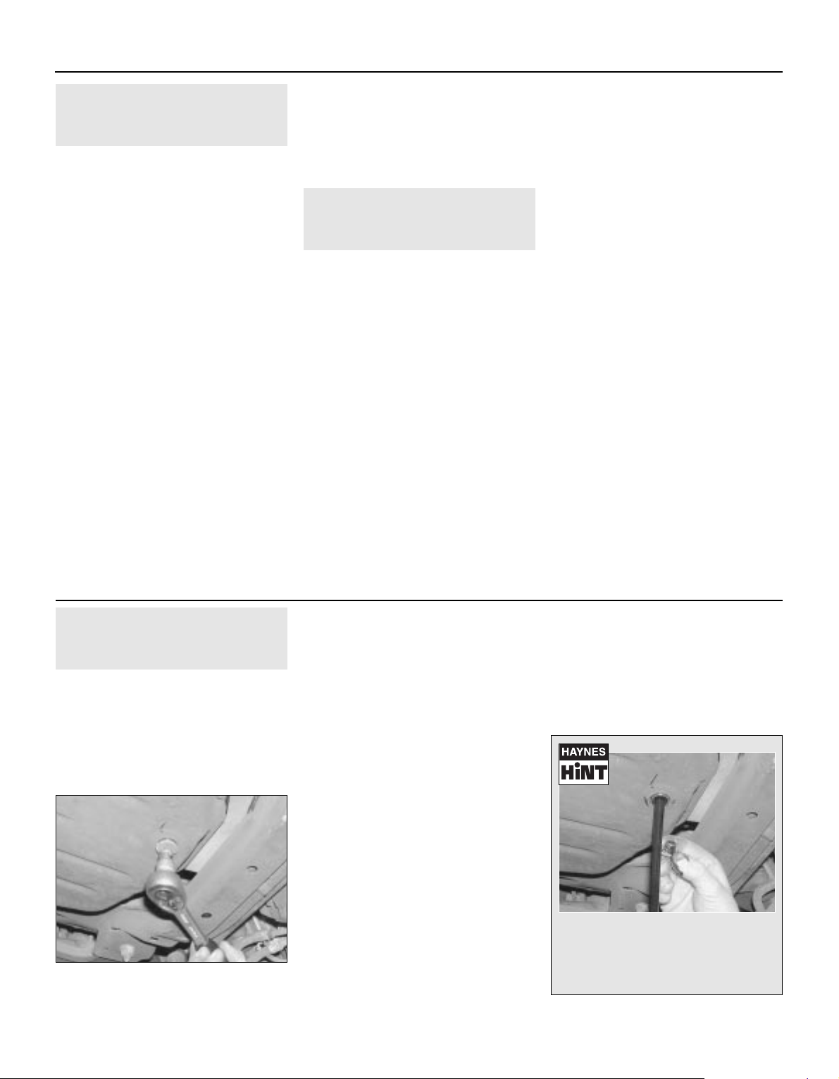
8 Move the container into position under the
oil filter. On 2.0 litre engines the filter is
located on the front end of the engine, where
1•6 Maintenance procedures
3.5 Removing the sump drain plug
3510 Vauxhall/Opel Omega
Every 5000 miles or 6 months
As the drain plug releases from the
threads, move it quickly away so that
the stream of oil running out of the
sump goes into the container and not
over your arm
Page 25

it is screwed onto the oil pump housing, and
on 2.5 and 3.0 litre engines it is screwed onto
the left-hand side of the cylinder block (see
illustration).
9 Use an oil filter removal tool to slacken the
filter initially, then unscrew it by hand the rest
of the way. Empty the oil from the old filter
into the container.
10 Use a clean rag to remove all oil, dirt and
sludge from the filter sealing area on the
engine.
11 Apply a light coating of clean engine oil
to the sealing ring on the new filter, then
screw the filter into position on the engine.
Tighten the filter firmly by hand only - do not
use any tools (see illustrations). If a genuine
filter is being fitted and the special oil filter
tool (Tool no. KM-726A - a socket which fits
over the end of the filter) is available, tighten
the filter to the specified torque.
12 Refit the undercover, tightening its
retaining screws securely, then remove the
old oil and all tools from under the vehicle
before lowering the vehicle to the ground.
13 Fill the engine through the filler hole, using
the correct grade and type of oil (refer to
Weekly Checks for details of topping-up).
Pour in half the specified quantity of oil first,
then wait a few minutes for the oil to drain into
the sump. Continue to add oil, a small
quantity at a time, until the level is up to the
lower mark on the dipstick. Adding
approximately a further 1.0 litre will bring the
level up to the upper mark on the dipstick.
14 Start the engine and run it for a few
minutes, while checking for leaks around the
oil filter seal and the sump drain plug. Note
that there may be a delay of a few seconds
before the low oil pressure warning light goes
out when the engine is first started, as the oil
circulates through the new oil filter and the
engine oil galleries before the pressure builds
up.
15 Stop the engine, and wait a few minutes
for the oil to settle in the sump once more.
With the new oil circulated and the filter now
completely full, recheck the level on the
dipstick, and add more oil as necessary.
16 Dispose of the used engine oil safely with
reference to General repair procedures.
Every 5000 miles 1•7
1
3.8 Oil filter location - 2.0 litre engine 3.11a Lubricate the sealing ring of the new
filter with a smear of engine oil . . .
3.11b . . . then screw the filter on by hand
only (2.5 litre engine shown)
3510 Vauxhall/Opel Omega
4 Monitoring, lighting and
signalling equipment -
check
1
1 Turn the ignition switch to the second
position and check that the instrument panel
CHECK lamp lights up and then extinguishes
after 4 approximately seconds. If the lamp
fails to extinguish, observe the fault
description message(s) displayed and rectify
the cause.
2 Start the engine and check that all tell-tale
system operation/fault lamps extinguish. Note
that some lamps (such as the automatic
transmission sport programme, or traction
control system lamps) may remain lit,
depending on the driving mode selected;
consult your drivers handbook for the exact
meaning of each lamp.
3 Release handbrake, depress the brake
pedal and check that the brake lights fault
display extinguishes.
4 Switch on all interior and exterior lights in
turn and check their operation. Pay particular
attention to the tail lamps, fog lamps, brake
lamps, main and dipped beam headlamps,
position lamps and front and rear direction
indicators. Renew any blown bulbs with
reference to Chapter 12.
5 Finally, check the operation of the horn.
5 Front and rear brakes -
pad and disc wear check
2
Front brakes
1 Firmly apply the handbrake, select first gear
or P, then jack up the front of the vehicle and
support it securely on axle stands (see
Jacking and Vehicle Support). Remove the
front roadwheels.
2 For a quick check, the pad thickness can
be carried out via the inspection hole on the
front surface of each caliper (see illustration).
Using a steel rule, measure the thickness of
each pad lining, including the backing plate.
This must not be less than that indicated in
the Specifications.
3 The view through the caliper inspection
hole gives only a rough indication of the
state of the brake pads. For a comprehensive
check, the brake pads should be removed
and cleaned. The operation of the caliper can
then also be checked, and the condition of the
brake disc itself can be fully examined on both
sides. Chapter 9 contains a detailed
description of how the brake discs should be
checked for wear and/or damage.
4 If any pad’s friction material is worn to the
specified thickness or less, all four pads must
be renewed as an axle set; for example - if the
pads in the left hand caliper are found to be
worn, those in the right hand caliper must also
be renewed, regardless of their condition.
Refer to Chapter 9 for details.
5 On completion, refit the roadwheels and
lower the vehicle to the ground.
Rear brakes
6 Chock the front wheels, then jack up the
rear of the vehicle and support it securely on
axle stands (see Jacking and Vehicle
Support). Remove the rear roadwheels.
Every 10 000 miles or 12 months
5.2 The brake pad wear can be assessed
by observing the thickness of the friction
material, visible through the inspection
aperture at the front of the brake caliper
Page 26

7 Proceed as described in paragraphs 2 to 4
inclusive, noting that the inspection aperture
is at the rear of the caliper.
8 On completion, refit the rear roadwheels
and lower the vehicle to the ground.
6 Auxiliary drivebelt -
check and renewal
3
Check
1 Although the drivebelt tension is
automatically adjusted by the spring-loaded
tensioner, the belt itself should still be
regularly checked for damage or deterioration.
2 With the engine stopped, inspect the full
length of the drivebelt for cracks and
separation of the belt plies. It will be
necessary to turn the engine (using a spanner
or socket and bar on the crankshaft pulley
bolt) in order to move the belt from the pulleys
so that the belt can be inspected thoroughly.
Twist the belt between the pulleys so that
both sides can be viewed. Also check for
fraying, and glazing which gives the belt a
shiny appearance. Check the pulleys for
nicks, cracks, distortion and corrosion.
3 Check the position of the drivebelt
tensioner assembly arm in relation to the
backplate. On 2.0 litre engines the arm
indicator should be in between the stops on
the backplate and should be free to move. On
2.5 and 3.0 litre engines the stop on the
tensioner mounting plate should be
positioned between the lugs on the arm and
the arm should be free to move (see
illustrations).
4 If the belt shows signs of wear or damage,
or the tensioner arm is against the stop, the
belt must be renewed.
Renewal
2.0 litre engine
5 Prior to removal make a note of the correct
routing of the belt around the various pulleys.
If the belt is to be reused, also mark the
direction of rotation on the belt to ensure the
belt is refitted the same way around.
6 Using a suitable spanner or socket fitted to
the tensioner pulley centre bolt, lever the
tensioner away from the belt until there is
sufficient slack to enable the belt to be
slipped off from the pulleys. Carefully release
the tensioner pulley until it is against its stop
then remove the belt from the vehicle. If
necessary, the tensioner can be locked in the
released position by aligning the arm hole with
the hole in the backplate and inserting a
suitable tool/pin.
7 Manoeuvre the belt into position, routing it
correctly around the pulleys; if the original belt
is being fitted use the marks made prior to
removal to ensure it is fitted the correct way
around.
8 Lever the tensioner roller back against is
spring, and seat the belt on the pulleys.
Ensure the belt is centrally located on all
pulleys then slowly release the tensioner
pulley until the belt is correctly tensioned. Do
not allow the tensioner to spring back and
stress the belt.
9 Check the tensioner arm is correctly
positioned in relation to the backplate (see
paragraph 3).
2.5 and 3.0 litre engine
10 Remove the multi-ram air intake system
pre-volume chamber and the secondary air
injection system front connecting pipe as
described in the relevant Parts of Chapter 4.
11 Prior to removal make a note of the
correct routing of the belt around the various
pulleys. If the belt is to be reused, also mark
the direction of rotation on the belt to ensure
the belt is refitted the same way around.
12 Using a suitable spanner or socket fitted
to the tensioner pulley centre bolt, lever the
tensioner away from the belt until there is
sufficient slack to enable the belt to be
slipped off from the pulleys (see illustration).
Carefully release the tensioner pulley until it is
against its stop then remove the belt from the
vehicle.
13 Manoeuvre the belt into position, routing it
correctly around the pulleys; if the original belt
is being fitted use the marks made prior to
removal to ensure it is fitted the correct way
around.
14 Lever the tensioner roller back against is
spring, and seat the belt on the pulleys.
Ensure the belt is centrally located on all
pulleys then slowly release the tensioner
pulley until the belt is correctly tensioned. Do
not allow the tensioner to spring back and
stress the belt.
15 Check the tensioner arm is correctly
positioned in relation to the backplate (see
paragraph 3) then refit the secondary air
injection system connecting pipe and the
multi-ram air intake system pre-volume
chamber as described in the relevant part of
Chapter 4.
1•8 Every 10 000 miles
6.12 Lever the tensioner away from the
belt then slip the belt off from its pulleys
(2.5 litre engine shown)
3510 Vauxhall/Opel Omega
6.3a On 2.0 litre engines check that the drivebelt tensioner arm
indicator (2) is correctly positioned between the stops (1 and 3) on
the backplate
6.3b On 2.5 and 3.0 litre engines ensure the stop (1) on the
drivebelt tensioner mounting plate is in between the lugs (2) on
the arm
Page 27
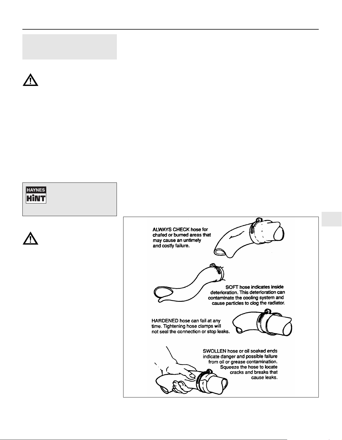
7 Underbonnet/underbody
hose and fluid leak -
check
2
Cooling system
Warning: Refer to the safety
information given in Safety First
and Chapter 3 before disturbing
any of the cooling system components.
1 Carefully check the radiator and heater
coolant hoses along their entire length. Renew
any hose which is cracked, swollen or which
shows signs of deterioration. Cracks will show
up better if the hose is squeezed. Pay close
attention to the clips that secure the hoses to
the cooling system components. Hose clips
that have been over-tightened can pinch and
puncture hoses, resulting in cooling system
leaks (see illustration).
2 Inspect all the cooling system components
(hoses, joint faces, etc) for leaks. Where any
problems of this nature are found on system
components, renew the component or gasket
with reference to Chapter 3.
Fuel system
Warning: Refer to the safety
information given in Safety First
and Chapter 4A before disturbing
any of the fuel system components.
3 Petrol leaks can be difficult to pinpoint,
unless the leakage is significant and hence
easily visible. Fuel tends to evaporate quickly
once it comes into contact with air, especially
in a hot engine bay. Small drips can disappear
before you get a chance to identify the point
of leakage. If you suspect that there is a fuel
leak from the area of the engine bay, leave the
vehicle overnight then start the engine from
cold, with the bonnet open. Metal
components tend to shrink when they are
cold, and rubber seals and hoses tend to
harden, so any leaks will be more apparent
whilst the engine is warming up from a cold
start.
4 Check all fuel lines at their connections to
the fuel rail, fuel pressure regulator and fuel
filter (petrol models), Examine each rubber
fuel hose along its length for splits or cracks.
Check for leakage from the crimped joints
between rubber and metal fuel lines. Examine
the unions between the metal fuel lines and
the fuel filter housing. Also check the area
around the fuel injectors for signs of O-ring
leakage.
5 To identify fuel leaks between the fuel tank
and the engine bay, the vehicle should raised
and securely supported on axle stands.
Inspect the petrol tank and filler neck for
punctures, cracks and other damage. The
connection between the filler neck and tank is
especially critical. Sometimes a rubber filler
neck or connecting hose will leak due to loose
retaining clamps or deteriorated rubber.
6 Carefully check all rubber hoses and metal
fuel lines leading away from the petrol tank.
Check for loose connections, deteriorated
hoses, kinked lines, and other damage. Pay
particular attention to the vent pipes and
hoses, which often loop up around the filler
neck and can become blocked or kinked,
making tank filling difficult. Follow the fuel
supply and return lines to the front of the
vehicle, carefully inspecting them all the way
for signs of damage or corrosion. Renew
damaged sections as necessary.
Engine oil
7 Inspect the area around the camshaft
cover, cylinder head, oil filter and sump joint
faces. Bear in mind that, over a period of time,
some very slight seepage from these areas is
to be expected - what you are really looking
for is any indication of a serious leak caused
by gasket failure. Engine oil seeping from the
base of the timing belt cover or the
transmission bellhousing may be an indication
of crankshaft or transmission input shaft oil
seal failure. Should a leak be found, renew the
failed gasket or oil seal by referring to the
appropriate Chapters in this manual.
Automatic transmission fluid
8 Check the hoses leading to the
transmission fluid cooler for leakage. Look for
deterioration caused by corrosion and
damage from grounding, or debris thrown up
from the road surface. Automatic transmission
fluid is a thin oil and is usually red in colour.
Check the area around the propeller shaft seal
at the rear of the transmission for signs of fluid
leakage. Should a leak be found, check the
fluid level as described in Section 19 then
rectify the cause of leakage as soon as
possible.
Power assisted steering (PAS)
fluid
9 Examine the hose running between the fluid
reservoir and the power steering pump, and
the return hose running from the steering rack
to the fluid reservoir. Also examine the high
pressure supply hose between the pump and
the steering rack.
10 Check the condition of each hose
carefully. Look for deterioration caused by
corrosion and damage from grounding, or
debris thrown up from the road surface.
11 Pay particular attention to crimped
unions, and the area surrounding the hoses
that are secured with adjustable worm drive
clips. Like automatic transmission fluid, PAS
fluid is a thin oil, and is usually red or light
brown in colour.
Every 10 000 miles 1•9
1
3510 Vauxhall/Opel Omega
7.1 Possible causes of coolant hose failure
A leak in the cooling system
will usually manifest itself as
white or rust-coloured,
crusty deposits on the area
adjacent to the leak
Page 28
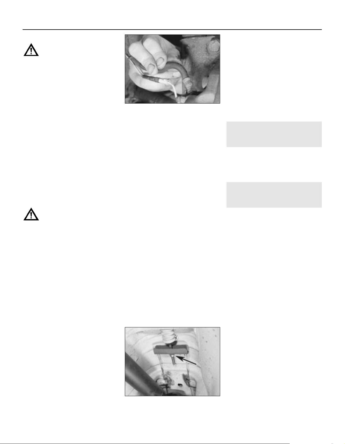
Air conditioning refrigerant
Warning: Refer to the safety
information given in Safety First
and Chapter 3, regarding the
dangers of disturbing any of the air
conditioning system components.
12 The air conditioning system is filled with a
liquid refrigerant, which is retained under high
pressure. If the air conditioning system is
opened and depressurised without the aid of
specialised equipment, the refrigerant will
immediately turn into gas and escape into the
atmosphere. If the liquid comes into contact
with your skin, it can cause severe frostbite. In
addition, the refrigerant contains substances
which are environmentally damaging; for this
reason, it should not be allowed to escape
into the atmosphere in an uncontrolled
fashion.
13 Any suspected air conditioning system
leaks should be immediately referred to a
Vauxhall dealer or air conditioning specialist.
Leakage will be shown up as a steady drop in
the level of refrigerant in the system.
14 Note that water may drip from the
condenser drain pipe, underneath the car,
immediately after the air conditioning system
has been in use. This is normal, and should
not be cause for concern.
Brake fluid
Warning: Refer to the safety
information given in Safety First
and Chapter 9, regarding the
dangers of handling brake fluid.
15 Examine the area surrounding the brake
pipe unions at the master cylinder for signs of
leakage. Check the area around the base of
fluid reservoir, for signs of leakage caused by
seal failure. Also examine the brake pipe
unions at the ABS hydraulic unit.
16 If fluid loss is evident, but the leak cannot
be pinpointed in the engine bay, the brake
calipers and underbody brake lines should be
carefully checked with the vehicle raised and
supported on axle stands (see illustration).
Leakage of fluid from the braking system is a
serious fault that must be rectified
immediately.
17 Brake/clutch hydraulic fluid is a toxic
substance with a watery consistency. New
fluid is almost colourless, but it becomes
darker with age and use.
Manual transmission fluid
18 Check the area around the propeller shaft
seal at the rear of the transmission for signs of
fluid leakage. Should a leak be found, check
the transmission fluid level as described in
Chapter 7A then rectify the cause of leakage
as soon as possible.
Final drive unit differential fluid
19 Check the area around the driveshaft and
propeller shaft seals, and the flange seal on
the rear of the final drive unit for signs of fluid
leakage. Should a leak be found, check the
differential fluid level as described in Chapter 8
then rectify the cause of leakage as soon as
possible.
Unidentified fluid leaks
20 If there are signs that a fluid of some
description is leaking from the vehicle, but
you cannot identify the type of fluid or its
exact origin, park the vehicle overnight and
slide a large piece of card underneath it.
Providing that the card is positioned in
roughly the right location, even the smallest
leak will show up on the card. Not only will
this help you to pinpoint the exact location of
the leak, it should be easier to identify the fluid
from its colour. Bear in mind, though, that the
leak may only be occurring when the engine is
running!
Vacuum hoses
21 Although the braking system is
hydraulically-operated, the brake servo unit
amplifies the effort applied at the brake pedal,
by making use of the vacuum in the inlet
manifold, generated by the engine. Vacuum is
ported to the servo by means of a large-bore
hose. Any leaks that develop in this hose will
reduce the effectiveness of the braking
system, and may affect the running of the
engine.
22 In addition, a number of the underbonnet
components, particularly the emission control
components, are driven by vacuum supplied
from the inlet manifold via narrow-bore rubber
and plastic hoses. A leak in a vacuum hose
means that air is being drawn into the hose
(rather than escaping from it) and this makes
leakage very difficult to detect. One method is
to use an old length of vacuum hose as a kind
of stethoscope - hold one end close to (but
not in!) your ear and use the other end to
probe the area around the suspected leak.
When the end of the hose is directly over a
vacuum leak, a hissing sound will be heard
clearly through the hose. Care must be taken
to avoid contacting hot or moving
components, as the engine must be running,
when testing in this manner. Renew any
vacuum hoses that are found to be defective.
8 Bodywork/underbody
corrosion protection -
check
5
1 This work should be carried out by a
Vauxhall/Opel dealer in order to validate the
vehicle warranty. The work includes a
thorough inspection of the vehicle paintwork
and underbody for damage and corrosion
9 Handbrake operation -
check and adjustment
2
1 Chock the front wheels, then jack up the
rear of the vehicle and support it securely on
axle stands (see Jacking and Vehicle
Support). Remove the rear roadwheels.
2 Fully release the handbrake lever, then
apply it to the third notch. Check that both
rear wheels can still rotate by attempting to
turn them by hand (ensure that the
transmission is in neutral). Release the
handbrake lever.
3 Fully apply the handbrake lever, so that the
rear wheels are locked, counting how many
notches the lever passes through. If the
handbrake lever passes through more than
seven notches before the rear wheels lock,
adjustment is required.
4 If adjustment is necessary, first fully release
the handbrake, then pull it up to the third
notch.
5 Working underneath the vehicle, unbolt the
exhaust system heat shields from the
floorpan. Locate the handbrake cable
adjustment nut, at the cable compensation
bar, above the propeller shaft. Fully slacken
the adjustment nut so that there is a small
amount of clearance between it and the
compensation bar (see illustration).
6 Working on one brake disc at a time,
position the hole in the disc over the serrated
adjustment nut on the adjuster at the top of
the backplate. Using a screwdriver inserted
through the hole, turn the nut until the brake
disc locks, then turn the nut in opposite
direction until the disc is just free (see
illustration). Repeat the adjustment on the
remaining rear brake.
1•10 Every 10 000 miles
7.16 Inspecting the flexible hose
connection to a front brake caliper
9.5 Handbrake cable adjustment nut
(arrowed)
3510 Vauxhall/Opel Omega
Page 29
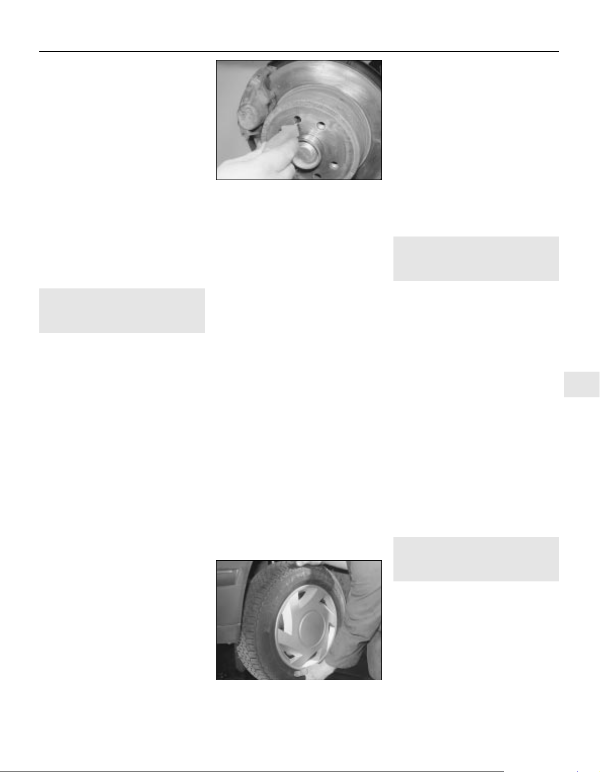
7 Check that the handbrake lever is still
positioned on the third notch, then working
underneath the vehicle, tighten the handbrake
cable adjustment nut against the
compensation bar, until the handbrake shoes
just start to take effect - test for this by turning
the brake discs by hand.
8 Refit the rear wheels, then carry out a final
check of the handbrake adjustment; the rear
wheels should turn freely with the lever
applied to the third notch and should be fully
locked before passing through the seventh
notch. Tighten the wheel bolts to the specified
torque then lower the car the ground. Check
the operation of the handbrake before using
the vehicle on the road.
9 After fitting new handbrake shoes, the
shoes should be bedded-in by driving a short
distance (approximately 300 metres) at low
speed with the handbrake lever lightly
applied. Check, and if necessary adjust the
handbrake again after completing the
bedding-in.
10 Suspension and steering
condition and operation -
check
2
Front suspension and steering
check
1 Raise the front of the vehicle, and securely
support it on axle stands (see Jacking and
Vehicle Support).
2 Visually inspect the balljoint dust covers
and the steering rack-and-pinion gaiters for
splits, chafing or deterioration. Any wear of
these components will cause loss of lubricant,
together with dirt and water entry, resulting in
rapid deterioration of the balljoints or steering
gear.
3 Check the power steering fluid hoses for
chafing or deterioration, and the pipe and
hose unions for fluid leaks. Also check for
signs of fluid leakage under pressure from the
steering gear rubber gaiters, which would
indicate failed fluid seals within the steering
gear.
4 Grasp the roadwheel at the 12 o’clock and
6 o’clock positions, and try to rock it (see
illustration). Very slight free play may be felt,
but if the movement is appreciable, further
investigation is necessary to determine the
source. Continue rocking the wheel while an
assistant depresses the footbrake. If the
movement is now eliminated or significantly
reduced, it is likely that the hub bearings are
at fault. If the free play is still evident with the
footbrake depressed, then there is wear in the
suspension joints or mountings.
5 Now grasp the wheel at the 9 o’clock and 3
o’clock positions, and try to rock it as before.
Any movement felt now may again be caused
by wear in the hub bearings or the steering
track-rod balljoints. If the outer balljoint is
worn, the visual movement will be obvious. If
the inner joint is suspect, it can be felt by
placing a hand over the rack-and-pinion
rubber gaiter and gripping the track-rod. If the
wheel is now rocked, movement will be felt at
the inner joint if wear has taken place.
6 Using a large screwdriver or flat bar, check
for wear in the suspension mounting bushes
by levering between the relevant suspension
component and its attachment point. Some
movement is to be expected, as the
mountings are made of rubber, but excessive
wear should be obvious. Also check the
condition of any visible rubber bushes,
looking for splits, cracks or contamination of
the rubber.
7 With the car standing on its wheels, have an
assistant turn the steering wheel back-andforth, about an eighth of a turn each way.
There should be very little, if any, lost
movement between the steering wheel and
roadwheels. If this is not the case, closely
observe the joints and mountings previously
described. In addition, check the steering
column universal joints for wear, and also
check the rack-and-pinion steering gear itself.
Rear suspension check
8 Chock the front wheels, then jack up the
rear of the vehicle and support securely on
axle stands (see Jacking and Vehicle
Support).
9 Working as described previously for the
front suspension, check the rear hub
bearings, the suspension bushes and the strut
or shock absorber mountings (as applicable)
for wear.
Shock absorber check
10 Check for any signs of fluid leakage
around the shock absorber body, or from the
rubber gaiter around the piston rod. Should
any fluid be noticed, the shock absorber is
defective internally, and should be renewed.
Note: Shock absorbers should always be
renewed in pairs on the same axle.
11 The efficiency of the shock absorber may
be checked by bouncing the vehicle at each
corner. Generally speaking, the body will
return to its normal position and stop after
being depressed. If it rises and returns on a
rebound, the shock absorber is probably
suspect. Also examine the shock absorber
upper and lower mountings for any signs of
wear.
11 Wheel bolt torque -
check and adjustment
2
Note: As well as being potentially damaging
to the vehicle’s roadwheels, over-tightened
wheel bolts may cause problems if you
have to change a wheel by the side of the
road. By ensuring that the wheel bolts are
tightened to the correct torque, you could
save yourself a lot of time and trouble in an
emergency situation.
1 Slacken the front wheel securing bolts
slightly, then apply the handbrake firmly, raise
the front of the vehicle, and securely support
it on axle stands (see Jacking and Vehicle
Support).
2 Fully slacken the each of the wheel bolts in
turn and clear any dirt of debris from the
threads. Re-insert the wheel bolts and tighten
them to the specified torque setting using a
good quality torque wrench.
3 Repeat the operation at the opposite wheel,
then lower the car the ground.
4 Chock the front wheels, then jack up the
rear of the vehicle and support securely on
axle stands (see Jacking and Vehicle
Support). Repeat the operations described in
paragraphs 2 and 3.
12 Headlight and auxiliary
driving light beam alignment
- check
5
1 Badly adjusted headlights and/or foglights
cause poor visibility and can dazzle other road
users. Accurate adjustment of the headlight
and auxiliary driving light beams is only
possible using optical beam-setting
equipment, and this work should therefore be
carried out by a Vauxhall/Opel dealer or
suitably-equipped workshop.
2 For reference, the headlights can be
adjusted using the adjuster assemblies fitted
to the front upper outer mounting and to the
rear inner mounting. The inner screw is for
horizontal adjustment and the outer one for
Every 10 000 miles 1•11
1
9.6 Adjusting the handbrake screws using
a screwdriver through the hole in the
disc/hub flange
10.4 To check for play in the wheel bearing,
grasp the roadwheel at the 12 o’clock and
6 o’clock positions, and try to rock it
3510 Vauxhall/Opel Omega
Page 30
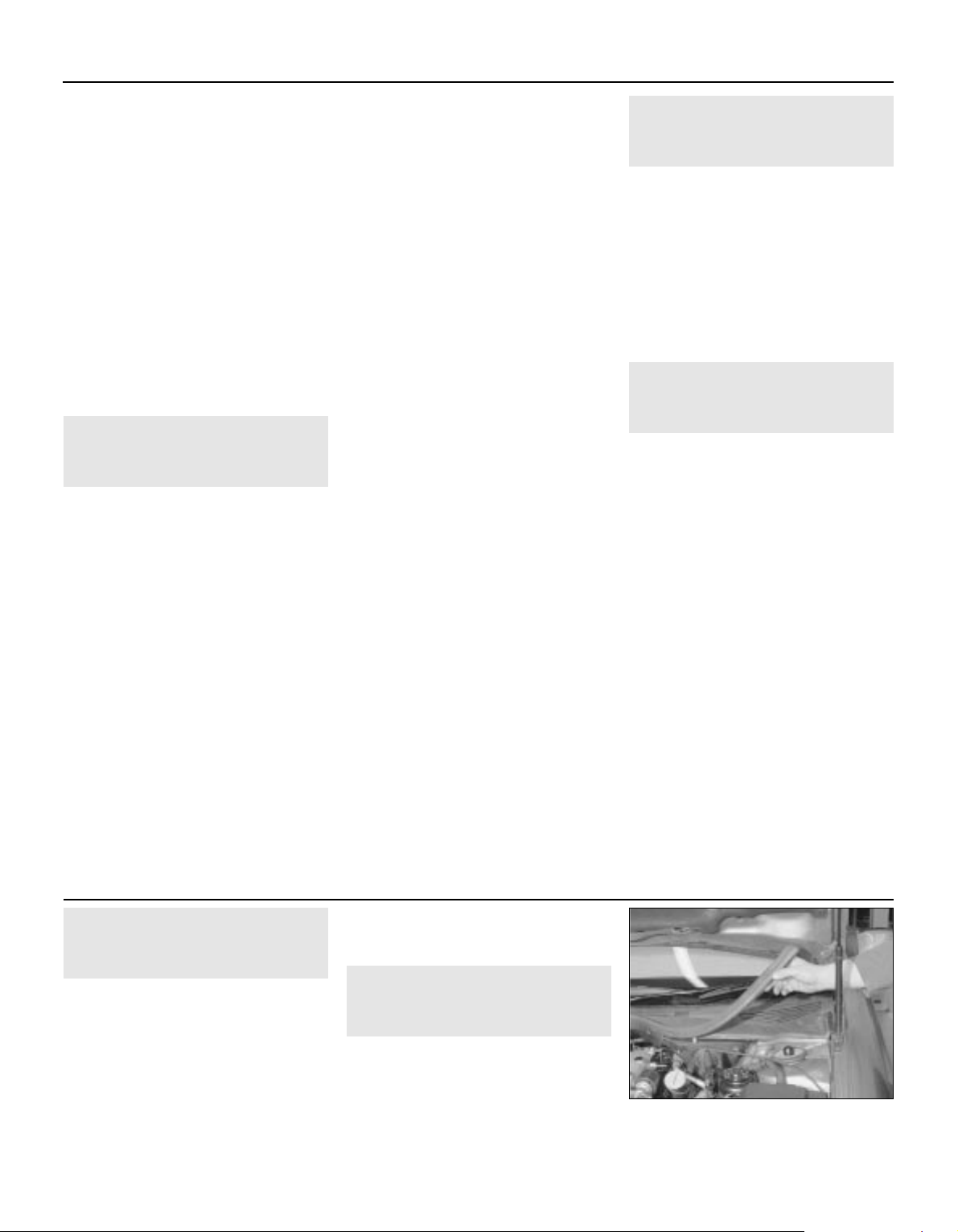
vertical adjustment. When adjusting the
headlight aim, ensure that the facia -mounted
range adjustment switch is set to position 0
(see paragraph 3).
3 All models have an electric headlight beam
adjustment range system, controlled via a
rotary switch in the facia*. The recommended
settings are as follows.
0 Front seat(s) occupied
1 All seats occupied
2 All seats occupied, and load in luggage
compartment
3 Driver’s seat occupied and load in the
luggage compartment
*On models built from 1998 onwards with
Xenon headlights, an automatic headlamp
range adjustment system is fitted, to which
no manual adjustment can be made; see
Chapter 12 for details.
13 Road test
1
Instruments and
electrical equipment
1 Check the operation of all instruments and
electrical equipment.
2 Make sure that all instruments read correctly,
and switch on all electrical equipment in turn, to
check that it functions properly.
Steering and suspension
3 Check for any abnormalities in the steering,
suspension, handling or road feel.
4 Drive the vehicle, and check that there are
no unusual vibrations or noises.
5 Check that the steering feels positive, with
no excessive sloppiness, or roughness, and
check for any suspension noises when
cornering and driving over bumps.
Drivetrain
6 Check the performance of the engine,
clutch, transmission and driveshafts.
7 Listen for any unusual noises from the
engine, clutch and transmission.
8 Make sure that the engine runs smoothly
when idling, and that there is no hesitation
when accelerating.
9 Check that, where applicable, the clutch
action is smooth and progressive, that the
drive is taken up smoothly, and that the pedal
travel is not excessive. Also listen for any
noises when the clutch pedal is depressed.
10 Check that all gears can be engaged
smoothly without noise, and that the gear
lever action is not abnormally vague or
notchy.
11 On automatic transmission models, make
sure that all gearchanges occur smoothly,
without snatching, and without an increase in
engine speed between changes. Check that
all of the gear positions can be selected with
the vehicle at rest. If any problems are found,
they should be referred to a Vauxhall/Opel
dealer.
Check the operation and
performance of the braking
system
12 Make sure that the vehicle does not pull to
one side when braking, and that the wheels
do not lock prematurely when braking hard.
13 Check that there is no vibration through
the steering when braking.
14 Check that the handbrake operates
correctly, without excessive movement of the
lever, and that it holds the vehicle stationary
on a slope.
15 Test the operation of the brake servo unit
as follows. Depress the footbrake four or five
times to exhaust the vacuum, then start the
engine. As the engine starts, there should be a
noticeable give in the brake pedal as vacuum
builds up. Allow the engine to run for at least
two minutes, and then switch it off. If the
brake pedal is now depressed again, it should
be possible to detect a hiss from the servo as
the pedal is depressed. After about four or five
applications, no further hissing should be
heard, and the pedal should feel considerably
harder.
14 Wheel alignment -
check
5
1 Accurate wheel alignment is essential for
positive, accurate steering, stable road
holding and to prevent abnormal tyre wear.
Wheel alignment checking is carried out with
the car loaded to its kerbside weight, and with
the tyre pressures correctly adjusted.
2 The front toe setting, front camber angle,
rear toe setting and rear camber angle are all
adjustable, but can only be checked using
specialised equipment; work of this nature
should therefore be entrusted to a garage or
suitably-equipped tyre specialist.
15 Exhaust system -
check
2
1 Park the vehicle on a level surface and
switch off the engine. Chock the front wheels,
then raise the rear of the vehicle and support
it securely on axle stands - refer to Jacking
and vehicle support in Reference.
2 With the engine cold (wait at least an hour
after switching off the engine), check the
complete exhaust system from the engine to
the end of the tailpipe.
3 Check the exhaust pipes and connections
for evidence of leaks, severe corrosion and
damage. Make sure that all brackets and
mountings are in good condition, and that all
relevant nuts and bolts are tight. Leakage at
any of the joints or in other parts of the system
will usually show up as a black, sooty stain in
the vicinity of the leak.
4 Rattles and vibrations can often be traced
to the exhaust system. Tap the silencer units
with a soft mallet and listen for noises caused
by corroded or displaced baffle material. Do
not strike the catalytic converter, as this may
damage the ceramic block inside.
5 Carefully rock the pipes and silencers from
side to side on their mountings. If the
components are able to come into contact
with the body or suspension parts, look for
broken or worn rubber mountings.
1•12 Every 10 000 miles
3510 Vauxhall/Opel Omega
16 Air filter element -
renewal
1
1 The air cleaner is located in the front righthand corner of the engine compartment.
2 Release the retaining clip and disconnect
the intake duct from the air cleaner housing.
3 Release the retaining clips then lift the air
cleaner cover and filter element out of position.
4 Wipe out the casing and the cover.
5 Fit the new filter, noting that the rubber
locating flange should be uppermost, and
secure the cover with the clips.
6 Reconnect the intake duct to the air cleaner
housing and secure it in position with the
retaining clip.
17 Pollen filter -
renewal
2
1 Open the bonnet and support it in the
upright position.
2 Carefully peel the rubber beading away
from the bulkhead seam, at the rear of the
engine compartment, on the drivers side of
the car (see illustration).
Every 20 000 miles or 2 years
17.2 Carefully peel the rubber beading
away from the bulkhead seam
Page 31

3 Hinge the grille panel upwards to expose
the pollen filter housing (see illustration).
4 Release the clips at either side of the
housing, then withdraw the pollen filter
element (see illustrations).
5 Slide the new filter element into the housing
and secure it in position with the clips.
6 Hinge the grille panel down over the
housing and press the rubber beading into
position on the bulkhead seam.
18 Lock and hinge lubrication
1
1 Work around the vehicle and lubricate the
hinges of the bonnet, doors and tailgate/boot
lid with a light machine oil.
2 Lightly lubricate the bonnet release
mechanism and exposed section of inner
cable with a smear of grease.
3 Check the security and operation of all
hinges, latches and locks, adjusting them
where required. Check the operation of the
central locking system.
4 Check the condition and operation of the
tailgate/boot lid struts, renewing them both if
either is leaking or no longer able to support
the tailgate/boot lid securely when raised.
19 Automatic transmission
fluid level -
check
3
1 The transmission fluid level must be
checked with the engine warm. For the check
to be accurate, Vauxhall state that the
transmission fluid temperature should ideally
be 60ºC but can be anywhere in the range of
45 to 85ºC (113 to 185ºF).
2 Take the vehicle on a short run to warm the
engine and transmission unit up to operating
temperature. On your return position the
vehicle over an inspection pit, on vehicle
ramps, or jack it up, but make sure that it is
level.
3 Start the engine and allow it to idle. Wipe
clean the area around the level plug which is
fitted to the right-hand side of the
transmission main sump (see illustration).
Unscrew the plug and clean it.
4 The oil level should reach the lower edge of
the level plug hole. If topping up is necessary,
add the specified type of oil through the level
plug hole until oil begins to trickle out.
5 Allow the excess oil to drain out then fit a
new sealing washer to the level plug and refit
it to the sump, tightening it to the specified
torque.
20 Handbrake -
shoe condition check
1 Refer to the information given in Chapter 9
for details.
21 Driveshaft gaiter condition -
check
2
1 Chock the front wheels, then jack up the rear
of the vehicle and support it on axle stands.
2 With the handbrake released turn each
wheel separately and check the driveshaft
rubber gaiters for splits and damage. Check
that the securing clips are in good condition
and shows no signs of damage or corrosion.
Driveshaft grease sprayed in a line along the
underside of the car, above the joint is a sign
that the gaiter has failed and requires renewal.
Every 20 000 miles 1•13
1
17.3 Hinge the grille panel upwards 17.4a Release the clips . . . 17.4b . . . then withdraw the pollen filter
element
19.3 Removing the automatic
transmission unit fluid level plug
3510 Vauxhall/Opel Omega
22 Spark plugs -
renewal
3
1 The correct functioning of the spark plugs is
vital for the correct running and efficiency of
the engine. It is essential that the plugs fitted
are appropriate for the engine; suitable types
are specified at the beginning of this Chapter,
or in the vehicle’s Owner’s Handbook. If the
correct type is used and the engine is in good
condition, the spark plugs should not need
attention between scheduled replacement
intervals. Spark plug cleaning is rarely
necessary, and should not be attempted unless
specialised equipment is available, as damage
can easily be caused to the firing ends.
2 On 2.0 litre DOHC engines, undo the
retaining screws and lift off the spark plug
cover from the top of the camshaft cover (see
illustration).
3 On 2.5 and 3.0 litre engines, carry out the
following operations referring to Chapter 4A
for further information.
a) Remove the idle speed control valve.
b) On models with air conditioning, undo the
retaining bolt and remove the air
conditioning pipe retaining clip from the
left-hand cylinder head.
Every 40 000 miles or 4 years
22.2 On 2.0 litre DOHC engine remove the
spark plug cover to gain access to the plugs
Page 32

c) Undo the bolts securing the wiring
harness cover to the inlet manifold and
position the harness clear of the left-hand
cylinder head spark plugs.
d) Unscrew the union nut and disconnect
the braking system servo unit vacuum
hose from the manifold.
e) To improve access to the plugs on the
right-hand cylinder head, unclip the
accelerator cable from its mounting
bracket then unbolt and remove the
mounting bracket from the inlet manifold.
4 On all engines, if the marks on the originalequipment spark plug (HT) leads cannot be
seen, mark the leads to correspond to the
cylinder the lead serves. Pull the leads from
the plugs by gripping the end fitting, not the
lead, otherwise the lead connection may be
fractured. On 2.0 litre DOHC engines and all
2.5 and 3.0 litre engines use the tool clipped
to one of the plug leads to pull the HT leads
from the plugs (see illustrations).
5 It is advisable to remove the dirt from the
spark plug recesses using a clean brush,
vacuum cleaner or compressed air before
removing the plugs, to prevent dirt dropping
into the cylinders.
6 Unscrew the plugs from the cylinder head
using a spark plug spanner, suitable box
spanner or a deep socket and extension bar.
Keep the socket aligned with the spark plug if it is forcibly moved to one side, the ceramic
insulator may be broken off. As each plug is
removed, examine it as follows.
7 Examination of the spark plugs will give a
good indication of the condition of the engine.
If the insulator nose of the spark plug is clean
and white, with no deposits, this is indicative
of a weak mixture or too hot a plug (a hot plug
transfers heat away from the electrode slowly,
a cold plug transfers heat away quickly).
8 If the tip and insulator nose are covered
with hard black-looking deposits, then this is
indicative that the mixture is too rich. Should
the plug be black and oily, then it is likely that
the engine is fairly worn, as well as the mixture
being too rich.
9 If the insulator nose is covered with light tan
to greyish-brown deposits, then the mixture is
correct and it is likely that the engine is in
good condition.
10 All engines are fitted with multi-electrode
plugs as standard by Vauxhall (see
illustration). On these plugs, the electrode
gaps are all preset and no attempt should be
made to bend the electrodes.
11 If non-standard single electrode plugs are
to be installed (this is not recommended), the
spark plug electrode gap is of considerable
importance. If the gap is too large or too
small, the size of the spark and its efficiency
will be seriously impaired and it will not
perform correctly under all engine speed and
load conditions. The gap should be set to the
value specified by the manufacturer.
12 To set the gap on a single electrode plug,
measure it with a feeler blade or spark plug
gap gauge and then carefully bend the outer
plug electrode until the correct gap is
achieved. The centre electrode should never
be bent, as this may crack the insulator and
cause plug failure, if nothing worse. If using
feeler blades, the gap is correct when the
appropriate-size blade is a firm sliding fit (see
illustrations).
13 Special spark plug electrode gap
adjusting tools are available from most motor
accessory shops, or from some spark plug
manufacturers (see illustration).
14 Before fitting the spark plugs, check that
the threaded connector sleeves are tight, and
that the plug exterior surfaces and threads are
clean.
1•14 Every 40 000 miles
22.4a Unclip the tool (arrowed) . . . 22.4b . . . and use it to pull the HT leads off
from the plugs (2.5 litre engine shown)
22.10 The multi-electrode plugs fitted as
standard should not be adjusted
22.12a If single electrode plugs are being
fitted, check the electrode gap using a
feeler gauge . . .
22.12b . . . or a wire gauge . . . 22.13 . . . and if necessary adjust the gap
by bending the electrode
3510 Vauxhall/Opel Omega
It is very often difficult to insert spark
plugs into their holes without crossthreading them. To avoid this possibility,
fit a short length of 5⁄16 inch internal
diameter rubber hose over the end of
the spark plug. The flexible hose acts as
a universal joint to help align the plug
with the plug hole. Should the plug
begin to cross-thread, the hose will slip
on the spark plug, preventing thread
damage to the aluminium cylinder head
Page 33

15 Remove the rubber hose (if used), and
tighten the plug to the specified torque using
the spark plug socket and a torque wrench.
Refit the remaining spark plugs in the same
manner.
16 Securely reconnect the HT leads in their
correct order.
17 On 2.0 litre DOHC engines refit the spark
plug cover and securely tighten its retaining
screws (see illustration).
18 On 2.5 and 3.0 litre engines carry out the
following operations, referring to Chapter 4A
for further information.
a) Refit the accelerator cable bracket to the
manifold and adjust the accelerator cable.
b) Reconnect the servo unit vacuum hose to
the manifold and tighten to the specified
torque.
c) Refit the wiring cover bolts and (where
necessary) the air conditioning pipe
bracket.
d) Refit the idle speed control valve.
23 Fuel filter -
renewal
3
1 The fuel filter is located under the rear of the
vehicle, just in front of the fuel tank.
2 Depressurise the fuel system as described
in Chapter 4A.
3 Chock the front wheels, then jack up the
rear of the vehicle and support on axle stands
(see Jacking and Vehicle Support).
4 Release the retaining clip holding the filter
to the underbody. Before removing the filter,
note the orientation of the fuel flow direction
arrow (see illustration).
5 Position a suitable container below the fuel
filter, to catch spilt fuel.
6 Release the connectors and disconnect the
fuel hoses from the fuel filter, noting their
locations to ensure correct refitting (see
illustration). A Vauxhall/Opel special tool is
available to disconnect the hose connectors,
but provided care it taken, the connections
can be released using a pair of pliers or a
screwdriver. Be prepared for fuel spillage, and
take adequate fire precautions.
7 Withdraw the filter from under the vehicle.
8 Fit the quick-release fitting clips to the new
filter offer up the filter making sure the flow
direction arrow on the filter body pointing in
the direction of fuel flow (see illustration).
9 Securely clip both hoses onto the filter then
secure the filter in position with the retaining
clip.
10 Start the engine and check the filter hose
unions for signs of leaks. If leakage is evident,
stop the engine immediately and rectify the
problem without delay.
11 If all is well, stop the engine and lower the
vehicle to the ground.
24 Timing belt -
renewal
1 Refer to the information given in Chapter 2A, 2B or 2C (as applicable).
Every 40 000 miles 1•15
1
22.17 On 2.0 litre DOHC engines refit the
spark plug cover and securely tighten its
retaining screws
23.4 Release the retaining clip and free
the fuel filter from the body
23.6 Depress the quick-release fitting tabs and detach the hoses
from the fuel filter
23.8 On refitting ensure the arrow (1) on the filter is pointing in
the direction of fuel flow and the quick-release fitting clips (2) are
correctly fitted
3510 Vauxhall/Opel Omega
25 Automatic transmission fluid
- renewal
1 Renew the transmission fluid and filter
assembly as described in Section 2 of
Chapter 7B.
Every 70 000 miles or 7 years
Page 34

26 Brake fluid -
renewal
3
Warning: Brake hydraulic fluid
can harm your eyes and damage
painted surfaces, so use extreme
caution when handling and pouring it. Do
not use fluid that has been standing open
for some time, as it absorbs moisture from
the air. Excess moisture can cause a
dangerous loss of braking effectiveness.
1 The procedure is similar to that for the
bleeding of the hydraulic system as described
in Chapter 9.
2 Working as described in Chapter 9, open
the first bleed screw in the sequence, and
pump the brake pedal gently until nearly all
the old fluid has been emptied from the
master cylinder reservoir. Top-up to the MAX
level with new fluid, and continue pumping
until only the new fluid remains in the
reservoir, and new fluid can be seen
emerging from the bleed screw. Tighten the
screw, and top the reservoir level up to the
MAX level line.
3 Work through all the remaining bleed screws
in the sequence until new fluid can be seen at
all of them. Be careful to keep the master
cylinder reservoir topped-up to above the MIN
level at all times, or air may enter the system
and greatly increase the length of the task.
4 When the operation is complete, check that
all bleed screws are securely tightened, and
that their dust caps are refitted. Wash off all
traces of spilt fluid, and recheck the master
cylinder reservoir fluid level.
5 Check the operation of the brakes before
taking the car on the road.
27 Remote control keyfob
battery -
renewal
1
Caution: The following procedure must be
completed within 3 minutes, otherwise the
remote control unit will have to be reprogrammed.
1 Using a small flat-bladed screwdriver, prise
the battery cover from the remote control unit.
2 Note how the battery is fitted, then carefully
remove it from the contacts.
3 Fit the new battery and refit the cover
making sure that it clips fully onto the base.
28 Coolant -
renewal
3
Cooling system draining
Warning: Wait until the engine is
cold before starting this
procedure. Do not allow antifreeze
to come in contact with your skin,
or with the painted surfaces of the vehicle.
Rinse off spills immediately with plenty of
water. Never leave antifreeze lying around
in an open container, or in a puddle in the
driveway or on the garage floor. Children
and pets are attracted by its sweet smell,
but antifreeze can be fatal if ingested.
1 With the engine completely cold, remove
the expansion tank filler cap. Turn the cap
anti-clockwise, wait until any pressure
remaining in the system is released, then
unscrew it and lift it off.
2 Where applicable, remove the engine
undershield, then position a suitable container
beneath the left hand side of the radiator.
3 Open the drain plug at the base of the
radiator, and allow the coolant to drain into
the container (see illustration).
4 When the flow of coolant stops, close the
drain plug securely.
5 If the coolant has been drained for a reason
other than renewal, then provided it is clean
and less than two years old, it can be re-used,
though this is not recommended.
Cooling system flushing
6 If coolant renewal has been neglected, or if
the antifreeze mixture has become diluted, then
in time, the cooling system may gradually lose
efficiency, as the coolant passages become
restricted due to rust, scale deposits, and other
sediment. The cooling system efficiency can be
restored by flushing the system clean.
7 The radiator should be flushed
independently of the engine, to avoid
unnecessary contamination.
Radiator flushing
8 Disconnect the top and bottom hoses and
any other relevant hoses from the radiator,
with reference to Chapter 3.
9 Insert a garden hose into the radiator top
inlet. Direct a flow of clean water through the
radiator, and continue flushing until clean
water emerges from the radiator bottom outlet.
10 If after a reasonable period, the water still
does not run clear, the radiator can be flushed
with a good proprietary cleaning agent. It is
important that the manufacturer’s instructions
are followed carefully. If the contamination is
particularly bad, remove the radiator, insert
the hose in the radiator bottom outlet, and
reverse-flush the radiator.
Engine flushing
11 Remove the thermostat as described in
Chapter 3 then, if the radiator top hose has
been disconnected from the engine, temporarily
reconnect the hose.
12 With the top and bottom hoses
disconnected from the radiator, insert a
garden hose into the radiator top hose. Direct
a clean flow of water through the engine, and
continue flushing until clean water emerges
from the radiator bottom hose.
13 On completion of flushing, refit the
thermostat and reconnect the hoses with
reference to Chapter 3.
Cooling system filling
14 Before attempting to fill the cooling
system, make sure that all hoses and clips are
in good condition, and that the clips are tight.
Note that an antifreeze mixture must be used
all year round, to prevent corrosion of the
engine components.
15 Remove the expansion tank filler cap, and
top the level up to the KALT/COLD mark.
6-cylinder engine models
16 Disconnect the heater supply (upper) hose
from the bulkhead connection (see Chapter 3).
17 Pour coolant into the disconnected heater
hose with the aid of a funnel, until no more
coolant will flow in, then reconnect the heater
hose to the bulkhead connection and tighten
the clip securely.
1•16 Every 2 years
28.3 Open the drain plug at the base of the
radiator (arrowed)
28.18 Slowly fill the system via the
expansion tank filler neck, until the coolant
level again reaches the KALT/COLD mark
on the side of the expansion tank
3510 Vauxhall/Opel Omega
Every 2 years, regardless of mileage
Old hydraulic fluid is
invariably much darker in
colour than the new, making
it easy to distinguish the
two.
Page 35

18 Slowly fill the system via the expansion
tank filler neck, until the coolant level again
reaches the KALT/COLD mark on the side of
the expansion tank (see illustration).
All models
19 Refit and tighten the expansion tank filler
cap.
20 Start the engine, and allow it to run until it
reaches normal operating temperature (until
the cooling fan cuts in and out). The cooling
system will bleed automatically as the engine
warms up.
21 Stop the engine, and allow it to cool, then
re-check the coolant level with reference to
Weekly checks. Top-up the level if necessary
and refit the expansion tank filler cap. Where
applicable, refit the engine undershield.
Antifreeze mixture
22 The antifreeze should always be renewed
at the specified intervals. This is necessary
not only to maintain the antifreeze properties,
but also to prevent corrosion which would
otherwise occur as the corrosion inhibitors
become progressively less effective.
23 Always use an ethylene-glycol based
antifreeze which is suitable for use in mixedmetal cooling systems. The quantity of
antifreeze and levels of protection are given in
the Specifications.
24 Before adding antifreeze, the cooling
system should be completely drained,
preferably flushed, and all hoses checked for
condition and security.
25 After filling with antifreeze, a label should
be attached to the expansion tank, stating the
type and concentration of antifreeze used,
and the date installed. Any subsequent
topping-up should be made with the same
type and concentration of antifreeze.
26 Do not use engine antifreeze in the windscreen/tailgate washer system, as it will cause
damage to the vehicle paintwork. A screenwash additive should be added to the washer
system in the quantities stated on the bottle.
Every 2 years 1•17
1
3510 Vauxhall/Opel Omega
Page 36

3510 Vauxhall/Opel Omega
2A•1
2A
Chapter 2 Part A:
2.0 litre SOHC engine in-car repair procedures
General
Engine type . . . . . . . . . . . . . . . . . . . . . . . . . . . . . . . . . . . . . . . . . . . . . . . Four-cylinder, in-line, water-cooled. Single overhead camshaft, belt-
driven, acting on hydraulic tappets
Manufacturer’s engine code:
Models with a catalytic converter . . . . . . . . . . . . . . . . . . . . . . . . . . . . X20SE
Models not fitted with a catalytic converter* . . . . . . . . . . . . . . . . . . . 20SE
Bore . . . . . . . . . . . . . . . . . . . . . . . . . . . . . . . . . . . . . . . . . . . . . . . . . . . . 86 mm
Stroke . . . . . . . . . . . . . . . . . . . . . . . . . . . . . . . . . . . . . . . . . . . . . . . . . . . 86 mm
Capacity . . . . . . . . . . . . . . . . . . . . . . . . . . . . . . . . . . . . . . . . . . . . . . . . . 1998 cc
Firing order . . . . . . . . . . . . . . . . . . . . . . . . . . . . . . . . . . . . . . . . . . . . . . . 1-3-4-2 (No 1 cylinder at timing belt end)
Direction of crankshaft rotation . . . . . . . . . . . . . . . . . . . . . . . . . . . . . . . Clockwise (viewed from timing belt end of engine)
Compression ratio . . . . . . . . . . . . . . . . . . . . . . . . . . . . . . . . . . . . . . . . . 10:1
Maximum power . . . . . . . . . . . . . . . . . . . . . . . . . . . . . . . . . . . . . . . . . . . 85 kW at 5400 rpm
Maximum torque . . . . . . . . . . . . . . . . . . . . . . . . . . . . . . . . . . . . . . . . . . . 178 Nm at 2800 rpm
*This model was never available in the UK
Compression pressures
Standard . . . . . . . . . . . . . . . . . . . . . . . . . . . . . . . . . . . . . . . . . . . . . . . . . 12 to 15 bar (174 to 218 psi)
Maximum difference between any two cylinders . . . . . . . . . . . . . . . . . . 1 bar (15 psi)
Camshaft
Endfloat . . . . . . . . . . . . . . . . . . . . . . . . . . . . . . . . . . . . . . . . . . . . . . . . . . 0.09 to 0.21 mm
Maximum permissible radial run-out . . . . . . . . . . . . . . . . . . . . . . . . . . . 0.04 mm
Lubrication system
Oil pump type . . . . . . . . . . . . . . . . . . . . . . . . . . . . . . . . . . . . . . . . . . . . . Gear type, driven directly from crankshaft
Minimum permissible oil pressure at idle speed, with engine
at operating temperature (oil temperature of at least 80°C) . . . . . . . . 1.5 bar (22 psi)
Oil pump clearances:
Gear teeth clearance . . . . . . . . . . . . . . . . . . . . . . . . . . . . . . . . . . . . . . 0.08 to 0.15 mm
Gear endfloat . . . . . . . . . . . . . . . . . . . . . . . . . . . . . . . . . . . . . . . . . . . 0.03 to 0.10 mm
Camshaft cover - removal and refitting . . . . . . . . . . . . . . . . . . . . . . . 4
Camshaft followers and hydraulic tappets - removal, inspection and
refitting . . . . . . . . . . . . . . . . . . . . . . . . . . . . . . . . . . . . . . . . . . . . . . 11
Camshaft housing and camshaft - removal, inspection and refitting 10
Camshaft oil seal - renewal . . . . . . . . . . . . . . . . . . . . . . . . . . . . . . . . 9
Compression test - description and interpretation . . . . . . . . . . . . . . 2
Crankshaft oil seals - renewal . . . . . . . . . . . . . . . . . . . . . . . . . . . . . . 16
Crankshaft pulley - removal and refitting . . . . . . . . . . . . . . . . . . . . . . 5
Cylinder head - removal and refitting . . . . . . . . . . . . . . . . . . . . . . . . 12
Engine oil and filter - renewal . . . . . . . . . . . . . . . . . . . . .See Chapter 1
Engine oil level check . . . . . . . . . . . . . . . . . . . . . . .See Weekly checks
Engine/transmission mountings - inspection and renewal . . . . . . . . 17
Flywheel/driveplate - removal, inspection and refitting . . . . . . . . . . . 15
General information . . . . . . . . . . . . . . . . . . . . . . . . . . . . . . . . . . . . . . 1
Oil pump - removal, overhaul and refitting . . . . . . . . . . . . . . . . . . . . 14
Sump - removal and refitting . . . . . . . . . . . . . . . . . . . . . . . . . . . . . . . 13
Timing belt - removal and refitting . . . . . . . . . . . . . . . . . . . . . . . . . . . 7
Timing belt covers - removal and refitting . . . . . . . . . . . . . . . . . . . . . 6
Timing belt tensioner and sprockets - removal and refitting . . . . . . . 8
Top dead centre (TDC) for No 1 piston - locating . . . . . . . . . . . . . . . 3
Specifications
Contents
Easy, suitable for
novice with little
experience
Fairly easy, suitable
for beginner with
some experience
Fairly difficult,
suitable for competent
DIY mechanic
Difficult, suitable for
experienced DIY
mechanic
Very difficult,
suitable for expert DIY
or professional
Degrees of difficulty
5
4
3
2
1
Page 37

Torque wrench settings Nm lbf ft
Camshaft cover bolts . . . . . . . . . . . . . . . . . . . . . . . . . . . . . . . . . . . . . . . 8 6
Camshaft sprocket bolt . . . . . . . . . . . . . . . . . . . . . . . . . . . . . . . . . . . . . 45 33
Camshaft thrustplate bolts . . . . . . . . . . . . . . . . . . . . . . . . . . . . . . . . . . . 8 6
Camshaft housing end cover bolts . . . . . . . . . . . . . . . . . . . . . . . . . . . . . 8 6
Connecting rod big-end bearing cap bolt:
Stage 1 . . . . . . . . . . . . . . . . . . . . . . . . . . . . . . . . . . . . . . . . . . . . . . . . 35 26
Stage 2 . . . . . . . . . . . . . . . . . . . . . . . . . . . . . . . . . . . . . . . . . . . . . . . . Angle-tighten a further 45°
Stage 3 . . . . . . . . . . . . . . . . . . . . . . . . . . . . . . . . . . . . . . . . . . . . . . . . Angle-tighten a further 15°
Coolant pump bolts . . . . . . . . . . . . . . . . . . . . . . . . . . . . . . . . . . . . . . . . 25 18
Crankcase breather tube bolts . . . . . . . . . . . . . . . . . . . . . . . . . . . . . . . . 25 18
Crankshaft pulley bolts . . . . . . . . . . . . . . . . . . . . . . . . . . . . . . . . . . . . . . 20 15
Crankshaft sensor rotor bolts . . . . . . . . . . . . . . . . . . . . . . . . . . . . . . . . . 13 10
Crankshaft sprocket bolt:
Stage 1 . . . . . . . . . . . . . . . . . . . . . . . . . . . . . . . . . . . . . . . . . . . . . . . . 130 96
Stage 2 . . . . . . . . . . . . . . . . . . . . . . . . . . . . . . . . . . . . . . . . . . . . . . . . Angle-tighten a further 40 to 50°
Cylinder head bolts:
Stage 1 . . . . . . . . . . . . . . . . . . . . . . . . . . . . . . . . . . . . . . . . . . . . . . . . 25 18
Stage 2 . . . . . . . . . . . . . . . . . . . . . . . . . . . . . . . . . . . . . . . . . . . . . . . . Angle-tighten a further 90°
Stage 3 . . . . . . . . . . . . . . . . . . . . . . . . . . . . . . . . . . . . . . . . . . . . . . . . Angle-tighten a further 90°
Stage 4 . . . . . . . . . . . . . . . . . . . . . . . . . . . . . . . . . . . . . . . . . . . . . . . . Angle-tighten a further 90°
Driveplate bolts:
Stage 1 . . . . . . . . . . . . . . . . . . . . . . . . . . . . . . . . . . . . . . . . . . . . . . . . 55 41
Stage 2 . . . . . . . . . . . . . . . . . . . . . . . . . . . . . . . . . . . . . . . . . . . . . . . . Angle-tighten a further 30°
Stage 3 . . . . . . . . . . . . . . . . . . . . . . . . . . . . . . . . . . . . . . . . . . . . . . . . Angle-tighten a further 15°
Engine/transmission mountings:
Left- and right-hand mountings:
Mounting-to-subframe nut . . . . . . . . . . . . . . . . . . . . . . . . . . . . . . . 55 41
Mounting-to-mounting bracket nut . . . . . . . . . . . . . . . . . . . . . . . . . 40 30
Mounting bracket-to-cylinder block bolts . . . . . . . . . . . . . . . . . . . . 60 44
Rear mounting:
Mounting-to-transmission bolts . . . . . . . . . . . . . . . . . . . . . . . . . . . 40 30
Mounting-to-crossmember nuts . . . . . . . . . . . . . . . . . . . . . . . . . . . 20 15
Crossmember-to-body bolts . . . . . . . . . . . . . . . . . . . . . . . . . . . . . 45 33
Engine to transmission support bracket bolts:
Bracket-to-engine bolt . . . . . . . . . . . . . . . . . . . . . . . . . . . . . . . . . . . . 40 30
Bracket-to-transmission bolts . . . . . . . . . . . . . . . . . . . . . . . . . . . . . . 22 16
Engine-to-transmission unit bolts . . . . . . . . . . . . . . . . . . . . . . . . . . . . . . 60 44
Flywheel bolts:
Stage 1 . . . . . . . . . . . . . . . . . . . . . . . . . . . . . . . . . . . . . . . . . . . . . . . . 65 48
Stage 2 . . . . . . . . . . . . . . . . . . . . . . . . . . . . . . . . . . . . . . . . . . . . . . . . Angle-tighten a further 30°
Stage 3 . . . . . . . . . . . . . . . . . . . . . . . . . . . . . . . . . . . . . . . . . . . . . . . . Angle-tighten a further 15°
Main bearing cap bolts:
Stage 1 . . . . . . . . . . . . . . . . . . . . . . . . . . . . . . . . . . . . . . . . . . . . . . . . 50 37
Stage 2 . . . . . . . . . . . . . . . . . . . . . . . . . . . . . . . . . . . . . . . . . . . . . . . . Angle-tighten a further 45°
Stage 3 . . . . . . . . . . . . . . . . . . . . . . . . . . . . . . . . . . . . . . . . . . . . . . . . Angle-tighten a further 15°
Oil filter . . . . . . . . . . . . . . . . . . . . . . . . . . . . . . . . . . . . . . . . . . . . . . . . . . 15 11
Oil pump:
Retaining bolts . . . . . . . . . . . . . . . . . . . . . . . . . . . . . . . . . . . . . . . . . . 8 6
Pump cover screws . . . . . . . . . . . . . . . . . . . . . . . . . . . . . . . . . . . . . . 6 4
Oil pressure relief valve bolt . . . . . . . . . . . . . . . . . . . . . . . . . . . . . . . . 50 37
Oil pump pick-up/strainer bolts . . . . . . . . . . . . . . . . . . . . . . . . . . . . . . . 8 6
Spark plug heatshields . . . . . . . . . . . . . . . . . . . . . . . . . . . . . . . . . . . . . . 25 18
Sump bolts:
Retaining bolts . . . . . . . . . . . . . . . . . . . . . . . . . . . . . . . . . . . . . . . . . . 8 6
Drain plug . . . . . . . . . . . . . . . . . . . . . . . . . . . . . . . . . . . . . . . . . . . . . . 55 41
Timing belt cover bolts:
Outer cover . . . . . . . . . . . . . . . . . . . . . . . . . . . . . . . . . . . . . . . . . . . . . 4 3
Rear cover . . . . . . . . . . . . . . . . . . . . . . . . . . . . . . . . . . . . . . . . . . . . . . 6 4
Timing belt tensioner bolt . . . . . . . . . . . . . . . . . . . . . . . . . . . . . . . . . . . . 20 15
2A•2 2.0 litre SOHC engine in-car repair procedures
3510 Vauxhall/Opel Omega
Page 38

1 General information
How to use this Chapter
1 This Part of Chapter 2 is devoted to in-car
repair procedures for the engine. All
procedures concerning engine removal and
refitting, and engine block/cylinder head
overhaul can be found in Chapter 2D.
2 Most of the operations included in this Part
are based on the assumption that the engine
is still installed in the car. Therefore, if this
information is being used during a complete
engine overhaul, with the engine already
removed, many of the steps included here will
not apply.
Engine description
3 The engine is a single overhead camshaft,
four-cylinder, in-line unit, mounted at the front
of the car with the clutch/transmission (as
applicable) on its rear.
4 The cylinder block is of the dry-liner type.
The crankshaft is supported within the
cylinder block on five shell-type main
bearings. Thrustwashers are fitted to number
3 main bearing, to control crankshaft endfloat.
5 The connecting rods are attached to the
crankshaft by horizontally split shell-type bigend bearings, and to the pistons by
interference-fit gudgeon pins. The aluminium
alloy pistons are of the slipper type, and are
fitted with three piston rings, comprising two
compression rings and a scraper-type oil
control ring.
6 The camshaft runs directly in the camshaft
housing, which is mounted on top of the
cylinder head, and driven by the crankshaft
via a toothed rubber timing belt (which also
drives the coolant pump). The camshaft
operates each valve via a follower. Each
follower pivots on a hydraulic self-adjusting
valve lifter (tappet) which automatically
adjusts the valve clearance.
7 Lubrication is by pressure-feed from a
gear-type oil pump, which is mounted on the
front end of the crankshaft. It draws oil
through a strainer located in the sump, and
then forces it through an externally mounted
full-flow cartridge-type filter. The oil flows into
galleries in the main bearing cap bridge
arrangement and cylinder block/crankcase,
from where it is distributed to the crankshaft
(main bearings) and camshaft. The big-end
bearings are supplied with oil via internal
drillings in the crankshaft, while the camshaft
bearings also receive a pressurised supply.
The camshaft lobes and valves are lubricated
by splash, as are all other engine
components.
8 A semi-closed crankcase ventilation system
is employed; crankcase fumes are drawn from
cylinder head cover, and passed via a hose to
the inlet manifold.
Repair operations possible with
the engine in the car
9 The following operations can be carried out
without having to remove the engine from the
vehicle:
a) Removal and refitting of the cylinder
head.
b) Removal and refitting of the timing belt
and sprockets.
c) Renewal of the camshaft oil seal.
d) Removal and refitting of the camshaft
housing and camshaft.
e) Removal and refitting of the sump.
f) Removal and refitting of the connecting
rods and pistons*.
g) Removal and refitting of the oil pump.
h) Renewal of the crankshaft oil seals.
i) Renewal of the engine mountings.
j) Removal and refitting of the
flywheel/driveplate.
* Although the operation marked with an
asterisk can be carried out with the engine in
the car after removal of the sump, it is better
for the engine to be removed, in the interests
of cleanliness and improved access. For this
reason, the procedure is described in
Chapter 2D.
2 Compression test -
description and interpretation
3
1 When engine performance is down, or if
misfiring occurs which cannot be attributed to
the ignition or fuel systems, a compression
test can provide diagnostic clues as to the
engine’s condition. If the test is performed
regularly, it can give warning of trouble before
any other symptoms become apparent.
2 The engine must be fully warmed-up to
normal operating temperature, the battery
must be fully charged, and the spark plugs
must be removed (see Chapter 1). The aid of
an assistant will also be required.
3 Ensure the ignition is switched off then
disable the ignition system by disconnecting
the wiring connector from the DIS module
(see Chapter 5B) and the fuel system by
removing the fuel pump relay from the engine
compartment relay box (see Chapter 4A,
Section 13).
4 Fit a compression tester to the number 1
cylinder spark plug hole the type of tester
which screws into the plug thread is to be
preferred.
5 Have the assistant hold the throttle wide
open and crank the engine on the starter
motor; after one or two revolutions, the
compression pressure should build up to a
maximum figure, and then stabilise. Record
the highest reading obtained.
6 Repeat the test on the remaining cylinders,
recording the pressure in each.
7 All cylinders should produce very similar
pressures; any difference greater than that
specified indicates the existence of a fault.
Note that the compression should build up
quickly in a healthy engine; low compression
on the first stroke, followed by graduallyincreasing pressure on successive strokes,
indicates worn piston rings. A low
compression reading on the first stroke, which
does not build up during successive strokes,
indicates leaking valves or a blown head
gasket (a cracked head could also be the
cause). Deposits on the undersides of the
valve heads can also cause low compression.
8 If the pressure in any cylinder is reduced to
the specified minimum or less, carry out the
following test to isolate the cause. Introduce a
teaspoonful of clean oil into that cylinder
through its spark plug hole, and repeat the
test.
9 If the addition of oil temporarily improves
the compression pressure, this indicates that
bore or piston wear is responsible for the
pressure loss. No improvement suggests that
leaking or burnt valves, or a blown head
gasket, may be to blame.
10 A low reading from two adjacent cylinders
is almost certainly due to the head gasket
having blown between them; the presence of
coolant in the engine oil will confirm this.
11 If one cylinder is about 20 per cent lower
than the others, and the engine has a slightly
rough idle, a worn camshaft lobe could be the
cause.
12 If the compression reading is unusually
high, the combustion chambers are probably
coated with carbon deposits. If this is the
case, the cylinder head should be removed
and decarbonised.
13 On completion of the test, refit the spark
plugs (see Chapter 1), refit the fuel pump relay
and reconnect the wiring connector to the DIS
module.
3 Top dead centre
(TDC) for No 1 piston -
locating
3
1 In its travel up and down its cylinder bore,
Top Dead Centre (TDC) is the highest point
that each piston reaches as the crankshaft
rotates. While each piston reaches TDC both
at the top of the compression stroke and
again at the top of the exhaust stroke, for the
purpose of timing the engine, TDC refers to
the piston position (usually number 1) at the
top of its compression stroke.
2 Number 1 piston (and cylinder) is at the
front (timing belt) end of the engine, and its
TDC position is located as follows. Note that
the crankshaft rotates clockwise when viewed
from the front of the vehicle.
3 Disconnect the battery negative terminal. If
necessary, remove all the spark plugs as
described in Chapter 1 to enable the engine to
be easily turned over.
4 To gain access to the camshaft sprocket
timing mark, remove the timing belt outer
cover as described in Section 6.
2.0 litre SOHC engine in-car repair procedures 2A•3
2A
3510 Vauxhall/Opel Omega
Page 39

5 Using a socket and extension bar on the
crankshaft sprocket bolt, turn the crankshaft
whilst keeping an eye on the camshaft
sprocket. Rotate the crankshaft until the
timing mark on the camshaft sprocket is
correctly aligned with the cutout on the top of
the timing belt rear cover and the mark on the
crankshaft sprocket rim is correctly aligned
with the cutout on the oil pump housing (see
illustration).
6 With the crankshaft pulley and camshaft
sprocket timing marks positioned as
described, the engine is positioned with No1
piston at TDC on its compression stroke.
4 Camshaft cover -
removal and refitting
2
Removal
1 Release the retaining clip and disconnect
the breather hose from the camshaft cover.
2 Slacken and remove the retaining bolts,
noting the correct fitted location of any clips
or brackets retained by the bolts (as
applicable) then lift the camshaft cover from
the camshaft housing. If the cover is stuck, do
not lever between the cover and camshaft
housing mating surfaces - if necessary, gently
tap the cover sideways to free it. Recover the
gasket; if it shows signs of damage or
deterioration it must be renewed.
Refitting
3 Prior to refitting, examine the inside of the
cover for a build-up of oil sludge or any other
contamination, and if necessary clean the
cover with paraffin, or a water-soluble solvent.
Examine the condition of the crankcase
ventilation filter inside the camshaft cover,
and clean as described for the inside of the
cover if clogging is evident (if desired, the filter
can be removed from the cover, after
removing the securing bolts). Dry the cover
thoroughly before refitting.
4 Ensure the cover is clean and dry and seat
the gasket in the cover recess then refit the
cover to the camshaft housing, ensuring the
gasket remains correctly seated.
5 Refit the retaining bolts, ensuring all relevant
clips/brackets are correctly positioned, and
tighten them to the specified torque working in
a diagonal sequence.
6 Reconnect the breather hose securely to
the cover.
5 Crankshaft pulley -
removal and refitting
2
Removal
1 Remove the auxiliary drivebelt as described
in Chapter 1. Prior to removal, mark the
direction of rotation on the belt to ensure the
belt is refitted the same way around.
2 Slacken and remove the small retaining
bolts securing the pulley to the crankshaft
sprocket and remove the pulley from the
engine. If necessary, prevent crankshaft
rotation by holding the sprocket retaining bolt
with a suitable socket.
Refitting
3 Seat the crankshaft pulley on the sprocket
and tighten its retaining bolts to the specified
torque.
4 Refit the auxiliary drivebelt as described in
Chapter 1 using the mark made prior to removal
to ensure the belt is fitted the correct way
around.
6 Timing belt covers -
removal and refitting
3
Outer cover
Removal
1 Remove the crankshaft pulley as described
in Section 5.
2 Undo the retaining bolt and free the wiring
harness guide from the top of the timing belt
cover.
2A•4 2.0 litre SOHC engine in-car repair procedures
3510 Vauxhall/Opel Omega
3.5 Align the camshaft sprocket timing mark with the cutout on the timing belt cover (1)
and align the crankshaft sprocket mark with the cutout on the oil pump housing (2) to
position No1 piston at TDC on its compression stroke
Page 40

3 Undo the remaining retaining bolts then
unclip the timing belt outer cover and remove
it from the engine.
Refitting
4 Refitting is the reverse of removal, ensuring
the auxiliary drivebelt is fitted the same way
around as it was prior removal.
Rear cover
Removal
5 Remove the camshaft and crankshaft
timing belt sprockets and the timing belt
tensioner as described in Section 8.
6 Free the crankshaft sensor wiring from the
base of the timing belt rear cover, noting its
correct routing.
7 Slacken and remove the bolts securing the
rear cover to the camshaft housing and oil
pump housing and remove the cover from the
engine.
Refitting
8 Refitting is the reverse of removal,
tightening the cover retaining bolts to the
specified torque. Ensure the crankshaft
sensor wiring is correctly routed before
refitting the timing belt components.
7 Timing belt -
removal and refitting
3
Note: The timing belt must be removed and
refitted with the engine cold.
Removal
1 Disconnect the battery negative terminal
then remove the timing belt outer cover as
described in Section 6. Note: On models with
a Vauxhall anti-theft warning system (ATWS),
the battery negative terminal must be
disconnected within 15 seconds of the
ignition being switched off to prevent the
alarm system being triggered.
2 Position No 1 cylinder at TDC on its
compression stroke as described in Section 3.
3 Slacken the timing belt tensioner bolt.
Using an Allen key, rotate the tensioner arm
clockwise to its stop, to relieve the tension in
the timing belt, and hold it in position by
securely tighten the retaining bolt (see
illustration).
4 Slide the timing belt off from its sprockets
and remove it from the engine. If the belt is to
be re-used, use white paint or similar to mark
the direction of rotation on the belt. Do not
rotate the crankshaft or camshaft until the
timing belt has been refitted.
5 Check the timing belt carefully for any signs
of uneven wear, splitting or oil contamination,
and renew it if there is the slightest doubt
about its condition. If the engine is undergoing
an overhaul and has covered 40 000 miles or
it was more than 4 years since the original belt
was fitted, renew the belt as a matter of
course, regardless of its apparent condition
(from 1997 onwards the belt renewal interval
was increased to 80 000 miles or 8 years). If
signs of oil contamination are found, trace the
source of the oil leak and rectify it, then wash
down the engine timing belt area and all
related components to remove all traces of oil.
Refitting
6 On reassembly, thoroughly clean the timing
belt sprockets then check that the camshaft
sprocket timing mark is still correctly aligned
with the rear cover cutout and the crankshaft
sprocket mark is still aligned with the mark on
the oil pump housing.
7 Fit the timing belt over the crankshaft and
camshaft sprockets, ensuring that the belt
left-hand run is taut (ie, all slack is on the
tensioner pulley side of the belt), then fit the
belt over the coolant pump sprocket and
tensioner pulley. Do not twist the belt sharply
while refitting it. Ensure that the belt teeth are
correctly seated centrally in the sprockets,
and that the timing marks remain in alignment.
If a used belt is being refitted, ensure that the
arrow mark made on removal points in the
normal direction of rotation, as before.
8 Slacken the timing belt tensioner bolt to
release the tensioner spring. Rotate the
tensioner arm anti-clockwise until the
tensioner pointer is fully over against its stop,
without exerting any excess strain on the belt
(see illustration). Hold the tensioner in
position and securely tighten its retaining bolt.
9 Check the sprocket timing marks are still
correctly aligned. If adjustment is necessary,
release the tensioner again then disengage
the belt from the sprockets and make any
necessary adjustments.
10 Using a socket on the crankshaft sprocket
bolt, rotate the crankshaft smoothly through
two complete turns (720º) in the normal
direction of rotation to settle the timing belt in
position.
11 Check that both the camshaft and
crankshaft sprocket timing marks are
correctly realigned then slacken the tensioner
bolt again.
12 If a new timing belt is being fitted, adjust
the tensioner so that the pointer is aligned
with either the cutout or NEW marking
(depending on type of tensioner fitted) on the
backplate (see illustration). Hold the
tensioner in the correct position and tighten
its retaining bolt to the specified torque.
Rotate the crankshaft smoothly through
another two complete turns in the normal
direction of rotation, to bring the sprocket
timing marks back into alignment. Check that
the tensioner pointer is still aligned with the
backplate cutout/marking (as applicable).
13 If the original belt is being refitted, adjust
the tensioner so that the pointer is either
positioned 4 mm to the left of the cutout or is
aligned with the USED marking (depending on
the type of tensioner fitted) on the backplate
(see illustration 7.12). Hold the tensioner in
the correct position and tighten its retaining
bolt to the specified torque. Rotate the
crankshaft smoothly through another two
complete turns in the normal direction of
2.0 litre SOHC engine in-car repair procedures 2A•5
2A
3510 Vauxhall/Opel Omega
7.3 Slacken the timing belt tensioner bolt (1) and rotate the
tensioner clockwise using an Allen key in the arm cutout (2)
7.8 Tension the belt by rotating the tensioner arm fully anticlockwise until the pointer is positioned as shown
Page 41

rotation, to bring the sprocket timing marks
back into alignment. Check that the tensioner
pointer is still correctly positioned in relation to
the backplate cutout/marking (as applicable).
14 If the tensioner pointer is not correctly
positioned in relation to the backplate, repeat
the procedure in paragraph 12 (new belt) or 13
(original belt) (as applicable).
15 Once the tensioner arm and backplate
remain correctly aligned, refit the timing belt
cover and crankshaft pulley as described in
Sections 5 and 6.
8 Timing belt tensioner
and sprockets -
removal and refitting
3
Camshaft sprocket
Removal
1 Remove the timing belt as described in
Section 7.
2 The camshaft must be prevented from
turning as the sprocket bolt is unscrewed, and
this can be achieved in one of two ways as
follows.
a) Make up a sprocket-holding tool using
two lengths of steel strip (one long, the
other short), and three nuts and bolts; one
nut and bolt forms the pivot of a forked
tool, with the remaining two nuts and
bolts at the tips of the ‘forks’ to engage
with the sprocket spokes as shown (see
illustration).
b) Remove the camshaft cover as described
in Section 4 and hold the camshaft with
an open-ended spanner on the flats
provided.
3 Unscrew the retaining bolt and washer and
remove the sprocket from the end of the
camshaft.
Refitting
4 Prior to refitting check the oil seal for signs
of damage or leakage, if necessary, renewing
it as described in Section 9.
5 Refit the sprocket to the end of the
camshaft, aligning its cutout with the
camshaft locating pin, then refit the retaining
bolt and washer (see illustration).
6 Tighten the sprocket retaining bolt to the
specified torque whilst prevent rotation using
the method employed on removal.
7 Refit the timing belt as described in Section
7 then (where necessary) refit the camshaft
cover as described in Section 4.
Crankshaft sprocket
Note: A new crankshaft sprocket retaining
bolt will be required on refitting.
Removal
8 Remove the timing belt as described in
Section 7.
9 The crankshaft must be prevented from
turning as the sprocket bolt is unscrewed (the
bolt is very tight), and this can be achieved in
anyone of the following ways.
a) Use the holding tool described in
paragraph 2 securing the tool to the
sprocket with two bolts screwed into
opposite pulley retaining bolt holes.
b) On manual transmission models have an
assistant select top gear and apply the
brakes firmly.
c) If the engine is removed from the vehicle
or the transmission unit has been
removed the flywheel/driveplate can be
locked as described in Section 15.
10 Unscrew the retaining bolt and washer
and remove the crankshaft sprocket from the
end of the crankshaft. Discard the bolt; a new
one must be used on refitting. If necessary,
remove the sprocket Woodruff key from the
crankshaft end and slide off the spacer.
Refitting
11 Slide the spacer (where removed) onto the
crankshaft then refit the Woodruff key to the
crankshaft slot.
12 Align the sprocket with the key and slide it
into position, ensuring the sprocket flange is
facing outwards. Fit the washer and new
retaining bolt.
2A•6 2.0 litre SOHC engine in-car repair procedures
8.5 Refit the camshaft sprocket making
sure the locating pin (1) engages with the
sprocket hole (2)
8.2 Using a home-made sprocket holding
tool to retain the camshaft sprocket whilst
the bolt is slackened
3510 Vauxhall/Opel Omega
7.12 Ensure the timing belt tensioner arm (1) is correctly positioned in relation to the
backplate cutout/marking (2) as described in text
A Correct position for new belt - engines
with an unmarked tensioner
B Correct position for new belt - engines
with a marked tensioner
C Correct position for used belt - engines
with an unmarked tensioner
D Correct position for used belt - engines
with a marked tensioner
Page 42

13 Lock the crankshaft by the method used
on removal, and tighten the sprocket retaining
bolt to the specified stage 1 torque setting
then angle-tighten the bolt through the
specified stage 2 angle, using a socket and
extension bar. It is recommended that an
angle-measuring gauge is used during the
final stages of the tightening, to ensure
accuracy. If a gauge is not available, use white
paint to make alignment marks between the
bolt head and sprocket prior to tightening; the
marks can then be used to check that the bolt
has been rotated through the correct angle.
14 Refit the timing belt as described in
Section 7.
Tensioner assembly
Removal
15 Remove the timing belt as described in
Section 7.
16 Slacken and remove the retaining bolt and
remove the tensioner assembly from the
engine.
Refitting
17 Fit the tensioner to the engine, making
sure that the lug on the backplate is correctly
located in the oil pump housing hole. Ensure
the tensioner is correctly seated then refit the
retaining bolt. Using an Allen key, rotate the
tensioner arm clockwise to its stop then
securely tighten the retaining bolt.
18 Refit the timing belt as described in
Section 7.
9 Camshaft oil seal -
renewal
3
1 Remove the camshaft sprocket as
described in Section 8.
2 Carefully punch or drill two small holes
opposite each other in the oil seal. Screw a
self-tapping screw into each, and pull on the
screws with pliers to extract the seal (see
illustration).
3 Clean the seal housing, and polish off any
burrs or raised edges which may have caused
the seal to fail in the first place.
4 Lubricate the lips of the new seal with clean
engine oil, and press it into position using a
suitable tubular drift (such as a socket) which
bears only on the hard outer edge of the seal
(see illustration). Take care not to damage
the seal lips during fitting; note that the seal
lips should face inwards.
5 Refit the camshaft sprocket as described in
Section 8.
10 Camshaft housing and
camshaft - removal,
inspection and refitting
4
Removal
1 The camshaft can only be removed once
the camshaft housing has been removed from
the engine. Since the camshaft housing is
secured in position by the cylinder head bolts,
it is not possible to remove the camshaft
without removing the cylinder head (see
Section 12). Note: In theory it is possible to
remove the camshaft housing once the
cylinder head bolts have been removed, and
leave the head in position. However, this
procedure carries a high risk of disturbing the
head gasket, resulting in the head gasket
blowing once the camshaft and housing are
refitted. If you wish to attempt this, proceed as
described in Section 12, noting that it will not
be necessary to remove the manifolds, etc. Be
warned though that after refitting, you may
find the head gasket will need renewing,
meaning that the cylinder head will have to be
removed after all. The decision is yours as to
whether this is a chance worth taking.
2 With the camshaft housing removed, undo
the retaining bolts and remove the end cover
and gasket from the rear of the housing.
Discard the gasket, a new one should be used
on refitting.
3 Measure the camshaft endfloat by inserting
feeler gauges between the thrustplate and the
camshaft; if the endfloat is not within the limits
given in the Specifications then the thrustplate
will need to be renewed. Unscrew the two
retaining bolts then slide out the camshaft
thrustplate, noting which way round it is fitted
(see illustrations).
4 Carefully withdraw the camshaft from the
rear of the housing, taking care not to damage
the bearing journals (see illustration).
Inspection
5 With the camshaft removed, examine the
bearings in the camshaft housing for signs of
obvious wear or pitting. If evident, a new
camshaft housing will probably be required.
Also check that the oil supply holes in the
camshaft housing are free from obstructions.
6 The camshaft itself should show no marks
or scoring on the journal or cam lobe
surfaces. If evident, renew the camshaft. If the
camshaft lobes show signs of wear also
examine the followers (see Section 11). Check
the camshaft thrustplate for signs of wear or
grooves, and renew if necessary.
Refitting
7 Carefully prise the old seal out of from the
camshaft housing, using a suitable
2.0 litre SOHC engine in-car repair procedures 2A•7
2A
9.2 Removing the camshaft oil seal 9.4 Fitting a new camshaft oil seal
10.3a Undo the retaining bolts
(arrowed) . . .
10.3b . . . then remove the thrustplate . . . 10.4 . . . and slide the camshaft out from
the housing
3510 Vauxhall/Opel Omega
Page 43

screwdriver. Ensure the housing is clean then
press the in new seal, ensuring its sealing lip
is facing inwards, until it is flush with the
housing.
8 Liberally lubricate the camshaft and
housing bearings and the oil seal lip with fresh
engine oil.
9 Carefully insert the camshaft into the
housing, taking care not to mark the bearing
surfaces or damage the oil seal lip.
10 Slide the thrustplate into position, engaging it with the camshaft slot, and tighten its
retaining bolts to the specified torque. Check
the camshaft endfloat (see paragraph 3).
11 Ensure the mating surfaces are clean and
dry and fit a new gasket to the rear of the
housing. Refit the cover and tighten its
retaining bolts to the specified torque.
12 Refit the camshaft housing as described
in Section 12.
11 Camshaft followers and
hydraulic tappets - removal,
inspection and refitting
4
Using Vauxhall service tool
(tool no. KM-565)
1 If access to the special tool (KM-565) or a
suitable equivalent can be gained, the cam
followers and tappets can be removed as
follows, without disturbing the camshaft.
2 Remove the camshaft cover as described in
Section 4.
3 Using a socket and extension bar, rotate the
crankshaft in the normal direction of rotation
until the camshaft lobe of the first follower/
tappet to be removed is pointing straight
upwards. Remove the spark plug from the
corresponding cylinder (see Chapter 1).
4 Fit the service tool to the top of the
camshaft housing, making sure the tool end is
correctly engaged with the top of the valve.
Screw the tool stud into one of the housing
bolt holes until the valve is sufficiently
depressed to allow the follower to be slid out
from underneath the camshaft. The hydraulic
tappet can then also be removed as can the
thrust pad from the top of the valve. Inspect
the components (see paragraphs 10 and 11)
and renew if worn or damaged.
5 Lubricate the tappet and follower with fresh
engine oil then slide the tappet into its bore in
the cylinder head. Manoeuvre the follower into
position, ensuring it is correctly engaged with
the tappet and valve stem, then carefully
remove the service tool.
6 Repeat the operation on the remaining
followers and tappets then refit the spark
plug(s) (see Chapter 1).
Without special tool
Removal
7 Without the use of the special tool, it will be
necessary to remove the camshaft housing to
allow the followers and tappets to be removed
(see Section 10, paragraph 1).
8 With the housing removed, obtain eight
small, clean plastic containers, and number
them 1 to 8; alternatively, divide a larger
container into eight compartments. Lift out
each follower, thrust pad and hydraulic tappet
in turn, and place them in their respective
container (see illustrations). Do not
interchange the cam followers, or the rate of
wear will be much-increased.
Inspection
9 Examine the cam follower bearing surfaces
which contact the camshaft lobes for wear
ridges and scoring. Renew any follower on
which these conditions are apparent. If a
follower bearing surface is badly scored, also
examine the corresponding lobe on the
camshaft for wear, as it is likely that both will
be worn. Also check the thrust pad for signs
of wear or damage. Renew worn components
as necessary.
10 If the hydraulic tappets are thought to be
faulty they should be renewed; testing of the
tappets is not possible.
Refitting
11 Lubricate the hydraulic tappets and their
cylinder head bores with clean engine oil.
Refit the tappets to the cylinder head, making
sure they are fitted in their original locations.
12 Fit each thrust pad to the top of its
respective valve.
13 Lubricate the followers with clean engine
oil. Fit each follower, making sure it is
correctly located with both the tappet and
thrust pad, then refit the camshaft housing
(see Section 10).
12 Cylinder head -
removal and refitting
4
Removal
Note: The engine must be cold when
removing the cylinder head. New cylinder
head bolts must be used on refitting.
1 Disconnect the battery negative lead. Note:
On models with a Vauxhall anti-theft warning
system (ATWS), the battery negative terminal
must be disconnected within 15 seconds of
the ignition being switched off to prevent the
alarm system being triggered.
2 Drain the cooling system and remove the
spark plugs and auxiliary drivebelt as
described in Chapter 1.
3 Remove the timing belt as described in
Section 7. Prior to releasing the timing belt
tension and removing the belt, rotate the
crankshaft backwards by approximately 60º
(4 teeth of movement); this will position the
camshaft so that the valve spring pressure is
evenly exerted along its the complete length,
preventing the shaft turning and reducing the
risk of the valves contacting the pistons (see
illustration).
2A•8 2.0 litre SOHC engine in-car repair procedures
11.8a Remove each follower . . . 11.8b . . . thrust pad . . . 11.8c . . . and hydraulic tappet from the
cylinder head
12.3 Prior to removing the timing belt,
rotate the crankshaft 60º backwards to
ensure the camshaft and pistons are safely
positioned
3510 Vauxhall/Opel Omega
Page 44

4 Remove the inlet and exhaust manifolds as
described in Chapter 4A. If no work is to be
carried out on the cylinder head, the head can
be removed complete with manifolds once the
following operations have been carried out
(see Chapters 4A and 4B).
a) Remove the duct linking the air cleaner to
the throttle housing.
b) Disconnect the wiring connectors from
the throttle potentiometer, idle speed
adjuster, injectors, EGR valve, purge valve
and oxygen sensor. Unbolt the earth
connection from the fuel rail and release
all wiring from the inlet manifold.
c) Depressurise the fuel system then
disconnect the fuel hoses from the fuel
rail.
d) Disconnect the various vacuum and
coolant hoses from the inlet
manifold/throttle housing.
e) Unbolt the inlet manifold support bracket
and the alternator upper bracket.
f) Disconnect the accelerator cable.
g) Unbolt the exhaust front pipe from the
manifold and its mounting bracket.
5 Remove the camshaft cover as described in
Section 4.
6 Remove the camshaft sprocket as
described in Section 8.
7 Undo the retaining bolts securing the timing
belt rear cover to the camshaft housing.
8 Disconnect the wiring connectors from the
DIS module, the coolant temperature sensor,
the knock sensor and the crankshaft sensor.
Undo the bolt(s) securing the earth lead(s) to
the front of the cylinder head then position the
wiring cover assembly clear of the cylinder
head.
9 Slacken the retaining clips and disconnect
the coolant hoses from the thermostat
housing on the front end of the cylinder head.
Also disconnect the wiring connector from the
coolant temperature gauge sender unit on the
left-hand side of the thermostat housing.
10 Make a final check to ensure that all
relevant hoses, pipes and wires, etc, have
been disconnected.
11 Working in the reverse of the tightening
sequence (see illustration 12.29),
progressively slacken the cylinder head bolts
by a quarter of a turn at a time until all bolts
can be unscrewed by hand. Remove each
bolt in turn, along with its washer.
12 Lift the camshaft housing from the
cylinder head. If necessary, tap the housing
gently with a soft-faced mallet to free it from
the cylinder head, but do not lever at the
mating faces. Note the fitted positions of the
two locating dowels, and remove them for
safe keeping if they are loose.
13 Lift the cylinder head from the cylinder
block, taking care not to dislodge the cam
followers or thrust pads. If necessary, tap the
cylinder head gently with a soft-faced mallet
to free it from the block, but do not lever at
the mating faces. Note the fitted positions of
the two locating dowels, and remove them for
safe keeping if they are loose.
14 Recover the cylinder head gasket, and
discard it.
Preparation for refitting
15 The mating faces of the cylinder head and
block must be perfectly clean before refitting
the head. Use a scraper to remove all traces
of gasket and carbon, and also clean the tops
of the pistons. Take particular care with the
aluminium surfaces, as the soft metal is
damaged easily. Also, make sure that debris
is not allowed to enter the oil and water
channels - this is particularly important for the
oil circuit, as carbon could block the oil supply
to the camshaft or crankshaft bearings. Using
adhesive tape and paper, seal the water, oil
and bolt holes in the cylinder block. To
prevent carbon entering the gap between the
pistons and bores, smear a little grease in the
gap. After cleaning the piston, rotate the
crankshaft so that the piston moves down the
bore, then wipe out the grease and carbon
with a cloth rag. Clean the piston crowns in
the same way.
16 Check the block and head for nicks, deep
scratches and other damage. If slight, they
may be removed carefully with a file. More
serious damage may be repaired by
machining, but this is a specialist job.
17 If warpage of the cylinder head is
suspected, use a straight-edge to check it for
distortion. Refer to Chapter 2D if necessary.
18 Ensure that the cylinder head bolt holes in
the crankcase are clean and free of oil.
Syringe or soak up any oil left in the bolt
holes. This is most important in order that the
correct bolt tightening torque can be applied
and to prevent the possibility of the block
being cracked by hydraulic pressure when the
bolts are tightened.
19 Renew the cylinder head bolts regardless
of their apparent condition.
Refitting
20 Ensure the crankshaft is till positioned
approximately 60º BTDC and wipe clean the
mating faces of the head and block.
21 Ensure that the two locating dowels are in
position at each end of the cylinder
block/crankcase surface (see illustration).
22 Fit the new cylinder head gasket to the
block, making sure it is fitted with the correct
way up with its OBEN or TOP mark
uppermost and at the front end of the engine
(see illustration).
23 Carefully refit the cylinder head, locating it
on the dowels.
24 Ensure the mating surfaces of the cylinder
head and camshaft housing are clean and dry
and that all the camshaft followers are
correctly located with the tappets and thrust
pad.
25 Apply a bead of suitable sealant (Vauxhall
recommend the use of sealant 15 03 170 available from your Vauxhall dealer) to the
cylinder head mating surface (see
illustration).
26 Ensure the two locating dowels are in
position then lubricate the camshaft followers
with clean engine oil.
27 Carefully lower the camshaft housing
assembly into position, locating it on the
dowels.
28 Fit the washers to the new cylinder head
bolts then carefully insert them into position
(do not drop), tightening them finger-tight
only at this stage.
29 Working progressively and in the
sequence shown, first tighten all the cylinder
head bolts to the stage 1 torque setting (see
illustration).
30 Once all bolts have been tightened to the
stage 1 torque, again working in the sequence
shown, tighten each bolt through its specified
stage 2 angle, using a socket and extension bar.
2.0 litre SOHC engine in-car repair procedures 2A•9
2A
12.21 Fit the new gasket to the cylinder
block, engaging it with the locating dowels
(arrowed) . . .
12.22 . . . making sure its OBEN/TOP
marking is uppermost
12.25 Apply sealant to the cylinder head
upper mating surface then refit the
camshaft housing
3510 Vauxhall/Opel Omega
Page 45

It is recommended that an angle-measuring
gauge is used during this stage of the tightening,
to ensure accuracy (see illustration).
31 Working in the specified sequence, go
around again and tighten all bolts through the
specified stage 3 angle.
32 Finally go around in the specified
sequence again and tighten all bolts through
the specified stage 4 angle.
33 Refit the bolts securing the timing belt
rear cover to the camshaft housing and
tighten them to the specified torque.
34 Refit the camshaft sprocket as described
in Section 8.
35 Align all the sprocket timing marks to
bring the camshaft and crankshaft back to
TDC (see Section 3) then refit the timing belt
as described in Section 7.
36 Reconnect the wiring connectors to the
cylinder head components, ensuring all wiring
is correctly routed, and secure it in position
with the necessary clips.
37 Reconnect the coolant hoses to the
thermostat housings and securely tighten the
retaining clips.
38 Refit/reconnect the manifolds as
described in Chapter 4A.
39 Refit the undercover then lower the
vehicle to the floor.
40 Ensure all pipes and hoses are securely
reconnected then refill the cooling system and
refit the spark plugs as described in Chapter 1.
41 Reconnect the battery then start the
engine and check for signs of leaks.
13 Sump -
removal and refitting
3
Removal
Note: A new baffle plate will be required on
refitting (the sump gasket is an integral part of
the plate).
1 Disconnect the battery negative terminal.
Note: On models with a Vauxhall anti-theft
warning system (ATWS), the battery negative
terminal must be disconnected within 15
seconds of the ignition being switched off to
prevent the alarm system being triggered.
2 Firmly apply the handbrake then jack up the
front of the car and support it on axle stands.
Undo the retaining screws and remove the
undercover from beneath the engine.
3 Drain the engine oil as described in Chapter
1, then fit a new sealing washer and refit the
drain plug, tightening it to the specified
torque.
4 Where necessary, disconnect the wiring
connector from the oil level sender unit on the
sump.
5 Slacken and remove the bolts securing the
support brackets to the transmission housing
and sides of the cylinder block. Remove both
brackets from the engine then remove the
flywheel lower cover plate from the base of
the transmission housing.
6 Slacken and remove the nuts securing the
left- and right-hand engine mounting brackets
to the top of the rubber mountings. Unbolt the
right-hand mounting bracket and remove it
from the cylinder block.
7 Attach an engine hoist to the cylinder head
lifting brackets then raise the hoist until it is
supporting the weight of the engine.
8 Progressively slacken and remove the bolts
securing the sump to the base of the cylinder
block/oil pump. Break the sump joint by
striking the sump with the palm of the hand,
then lower the sump away from the engine
and withdraw it. Raise the engine unit slightly
to gain the necessary clearance required for
sump removal, taking care not to place any
excess strain on the engine wiring/hoses or
exhaust system.
9 Undo the retaining bolts and remove the oil
pump pick-up/strainer from the base of the oil
pump housing, noting the sealing ring, then
remove the baffle plate assembly.
10 Check the oil pump pick-up/strainer for
signs of clogging or splitting and renew/clean
as necessary. Note: If the sump is to be
removed for any length of time, refit the
mounting bracket to the cylinder block and
lower the engine back down onto its mounting
rubbers.
Refitting
11 Remove all traces of dirt and oil from the
mating surfaces of the sump, cylinder block
and oil pump housing. Also remove all traces
of locking compound from the threads of the
oil pump pick-up/strainer bolts and the sump
retaining bolts.
12 Apply a smear of suitable sealant
(Vauxhall recommend the use of sealant 15 03
295 - available from your Vauxhall dealer) to
the areas of the cylinder block mating surface
around the areas of the oil pump housing and
rear main bearing cap joints.
13 Fit a new sealing ring to the oil pump pickup/strainer and apply a few drops of locking
compound (Vauxhall recommend the use of
locking compound 15 10 181 - available from
your Vauxhall dealer) to the threads of the
strainer retaining bolts.
14 Offer up the new baffle plate, making sure
it is correctly located, then refit the oil pump
strainer tightening its retaining bolts to the
specified torque.
15 Apply a drop of locking compound to
each of the sump retaining bolts then offer up
the sump to the cylinder block. Refit the
retaining bolts and progressively tighten them
to the specified torque, working out from the
centre in a diagonal sequence.
16 Refit the mounting bracket to the cylinder
block and tighten its retaining bolts to the
specified torque. Lower the engine back down
onto its mountings making sure the brackets
and mounting rubbers are correctly aligned.
Remove the hoist from the engine then refit
the mounting nuts, tightening them to the
specified torque setting.
2A•10 2.0 litre SOHC engine in-car repair procedures
3510 Vauxhall/Opel Omega
12.29 Cylinder head bolt tightening sequence
12.30 Working in the specified sequence, tighten the cylinder
head bolts to the specified stage 1 torque setting and then
through the various specified angles (see text)
Page 46

17 Refit the flywheel lower cover plate to the
transmission housing then refit the support
brackets. Screw in the bolts securing the
brackets to the cylinder block and
transmission housing and tighten them to
their specified torque settings.
18 Reconnect the oil level sender wiring
connector (where fitted).
19 Refit the undercover then lower the
vehicle to the ground then fill the engine with
fresh oil, with reference to Chapter 1.
14 Oil pump -
removal, overhaul and refitting
4
Removal
1 Drain the engine oil as described in Chapter 1, then fit a new sealing washer and refit
the drain plug, tightening it to the specified
torque. Remove the oil filter and discard it.
2 Remove the timing belt as described in
Section 7.
3 Remove the camshaft and crankshaft
timing belt sprockets and the tensioner as
described in Section 8.
4 Unbolt the timing belt rear cover from the
camshaft housing and oil pump and remove it
from the engine.
5 Remove the sump and oil pump pickup/strainer as described in Section 13.
6 Disconnect the wiring connector from the
oil pressure switch.
7 Slacken and remove the retaining bolts
then slide the oil pump housing assembly off
of the end of the crankshaft, taking great care
not to lose the locating dowels. Remove the
housing gasket and discard it.
Overhaul
8 Undo the retaining screws and lift off the
pump cover from the rear of the housing (see
illustration).
9 Using a suitable marker pen, mark the
surface of both the pump inner and outer
gears; the marks can then be used to ensure
the rotors are refitted the correct way around.
10 Lift out the inner and outer gears from the
pump housing (see illustration).
11 Unscrew the oil pressure relief valve bolt
from the side of the housing and withdraw the
spring and plunger from the housing, noting
which way around the plunger is fitted (see
illustration). Remove the sealing washer from
the valve bolt. Note: The pressure relief valve
can be removed with pump in position on the
engine unit.
12 Clean the components, and carefully
examine the gears, pump body and relief
valve plunger for any signs of scoring or wear.
Renew any component which shows signs of
wear or damage; if the gears or pump housing
are marked then the complete pump
assembly should be renewed.
13 If the components appear serviceable,
measure the clearance between the inner gear
to outer gear clearance using feeler blades.
Also measure the gear endfloat, and check
the flatness of the end cover (see
illustrations). If the clearances exceed the
specified tolerances, the pump must be
renewed.
14 If the pump is satisfactory, reassemble the
components in the reverse order of removal,
noting the following.
a) Ensure both gears are fitted the correct
way around.
b) Fit a new sealing washer to the pressure
relief valve bolt and tighten the bolt to the
specified torque.
c) Remove all traces of locking compound
from the cover screws. Apply a drop of
fresh locking compound to each screw
and tighten the screws to the specified
torque.
d) On completion prime the oil pump by
filling it with clean engine oil whilst
rotating the inner gear.
Refitting
15 Prior to refitting, carefully lever out the
crankshaft oil seal using a flat-bladed
screwdriver. Fit the new oil seal, ensuring its
sealing lip is facing inwards, and press it
squarely into the housing using a tubular drift
which bears only on the hard outer edge of
the seal (see illustration). Press the seal into
position so that it is flush with the housing and
lubricate the oil seal lip with clean engine oil.
16 Ensure the mating surfaces of the oil
pump and cylinder block are clean and dry
and the locating dowels are in position.
17 Fit a new gasket to the cylinder block.
18 Carefully manoeuvre the oil pump into
position and engage the inner gear with the
crankshaft end. Locate the pump on the
dowels, taking great care not to damage the
oil seal lip.
2.0 litre SOHC engine in-car repair procedures 2A•11
2A
14.8 Undo the retaining screws and
remove the oil pump cover
14.10 Lift the inner and outer gears
(arrowed) out from the pump housing
14.11 Oil pressure relief valve components
1 Plunger
2 Spring
3 Sealing washer
4 Valve bolt
14.13a Using a feeler blade to check gear
clearance
14.13b Using a straight edge and feeler
blade to measure gear endfloat
14.15 Fitting a new crankshaft oil seal to
the oil pump housing
3510 Vauxhall/Opel Omega
Page 47

19 Refit the pump housing retaining bolts in
their original locations and tighten them to the
specified torque.
20 Reconnect the oil pressure sensor wiring
connector.
21 Refit the oil pump pick-up/strainer and
sump as described in Section 13.
22 Refit the rear timing belt cover to the
engine, tightening its retaining bolts to the
specified torque.
23 Refit the timing belt sprockets and
tensioner then refit the belt as described in
Sections 7 and 8.
24 On completion fit a new oil filter and fill the
engine with clean oil as described in Chapter 1.
15 Flywheel/driveplate -
removal, inspection
and refitting
4
Note: New flywheel/driveplate retaining bolts
will be required on refitting.
Removal
Manual transmission models
1 Remove the transmission as described in
Chapter 7A then remove the clutch assembly
as described in Chapter 6.
2 Prevent the flywheel from turning by locking
the ring gear teeth with a similar arrangement
to that shown (see illustration). Alternatively,
bolt a strap between the flywheel and the
cylinder block/crankcase. Make alignment
marks between the flywheel and crankshaft
using paint or a suitable marker pen.
3 Slacken and remove the retaining bolts and
remove the flywheel. Do not drop it, as it is
very heavy.
Automatic transmission models
4 Remove the transmission as described in
Chapter 7B.
5 Lock the driveplate as described in
paragraph 2 then slacken the driveplate
retaining bolts.
6 Unscrew the retaining bolts and remove the
retaining plate, centering ring and driveplate
from the end of the crankshaft, noting each
components correct fitted location.
Inspection
7 On manual transmission models, examine
the flywheel for scoring of the clutch face. If
the clutch face is scored, the flywheel may be
surface-ground, but renewal is preferable.
Check for wear or chipping of the ring gear
teeth. Renewal of the ring gear is possible on
models with a normal flywheel but is not a
task for the home mechanic; renewal requires
the new ring gear to be heated (up to 180º to
230ºC) to allow it to be fitted. On dual-mass
flywheels ring gear renewal is not possible.
8 On automatic transmission models closely
examine the driveplate for ring gear teeth for
signs of wear or damage and check the
driveplate surface for any signs of cracks.
9 If there is any doubt about the condition of
the flywheel/driveplate, seek the advice of a
Vauxhall dealer or engine reconditioning
specialist. They will be able to advise if it is
possible to recondition it or whether renewal
is necessary.
Refitting
Manual transmission models
10 Clean the mating surfaces of the flywheel
and crankshaft and remove all traces of
locking compound from the flywheel retaining
bolt threads in the crankshaft.
11 Offer up the flywheel and fit the new
retaining bolts. If the original is being refitted
align the marks made prior to removal.
12 Lock the flywheel by the method used on
removal, and tighten the retaining bolts to the
specified stage 1 torque setting then angletighten the bolts through the specified stage 2
angle, using a socket and extension bar, and
finally through the specified stage 3 angle. It is
recommended that an angle-measuring
gauge is used during the final stages of the
tightening, to ensure accuracy (see
illustrations). If a gauge is not available, use
white paint to make alignment marks between
the bolt head and flywheel prior to tightening;
the marks can then be used to check that the
bolt has been rotated through the correct
angle.
13 Refit the clutch as described in Chapter 6
then remove the locking tool, and refit the
transmission as described in Chapter 7A.
Automatic transmission models
14 Clean the mating surfaces of the driveplate
and crankshaft and remove all traces of
locking compound from the driveplate
retaining bolt threads in the crankshaft.
15 Offer up the driveplate complete with the
centering ring and retaining plate, making
sure all components are fitted the correct way
around, then screw in the new retaining bolts.
16 Tighten the retaining bolts through the
specified torque and angles as described in
paragraph 12 then remove the locking tool
and refit the transmission as described in
Chapter 7B.
16 Crankshaft oil seals -
renewal
4
Front (timing belt end) oil seal
1 Remove the crankshaft sprocket as
described in Section 8.
2 Carefully punch or drill two small holes
opposite each other in the oil seal. Screw a
self-tapping screw into each and pull on the
screws with pliers to extract the seal (see
illustration). Alternatively carefully lever the
seal out of position.
Caution: Great care must be taken to avoid
damage to the oil pump
3 Clean the seal housing and polish off any
burrs or raised edges which may have caused
the seal to fail in the first place.
2A•12 2.0 litre SOHC engine in-car repair procedures
15.2 Lock the flywheel/driveplate ring gear
with a tool similar to that shown
15.12a On manual transmission models,
tighten the flywheel bolts to the specified
stage 1 torque setting . . .
15.12b . . . then tighten them through the
specified stage 2 and 3 angles
16.2 Removing the crankshaft front oil
seal
3510 Vauxhall/Opel Omega
Page 48

4 Lubricate the lips of the new seal with clean
engine oil and ease it into position on the end
of the shaft. Press the seal squarely into
position until it is flush with the housing. If
necessary, a suitable tubular drift, such as a
socket, which bears only on the hard outer
edge of the seal can be used to tap the seal
into position (see illustration). Take great
care not to damage the seal lips during fitting
and ensure that the seal lips face inwards.
5 Wash off any traces of oil, then refit the
crankshaft sprocket as described in Section 8.
Rear (flywheel/driveplate end)
oil seal
6 Remove the flywheel/driveplate as
described in Section 15.
7 Renew the seal as described in paragraphs 2
to 4.
8 Refit the flywheel/driveplate as described in
Section 15.
17 Engine/transmission
mountings -
inspection and renewal
3
Inspection
1 If improved access is required, raise the
front of the car and support it securely on axle
stands. Undo the retaining bolts and remove
the undercover from beneath the engine unit.
2 Check the mounting rubber to see if it is
cracked, hardened or separated from the
metal at any point; renew the mounting if any
such damage or deterioration is evident.
3 Check that all the mounting’s fasteners are
securely tightened; use a torque wrench to
check if possible.
4 Using a large screwdriver or a pry bar,
check for wear in the mounting by carefully
levering against it to check for free play;
where this is not possible, enlist the aid of an
assistant to move the engine/transmission
unit back and forth, or from side to side, while
you watch the mounting. While some free play
is to be expected even from new
components, excessive wear should be
obvious. If excessive free play is found, check
first that the fasteners are correctly secured,
then renew any worn components as
described below.
Renewal
Left- and right-hand engine mountings
Note: It is recommended that the engine
mountings are replaced as a matched pair.
5 Firmly apply the handbrake then jack up the
front of the vehicle and support it on axle
stands. Undo the retaining screws and remove
the undercover from beneath the engine.
6 Support the weight of the engine/
transmission using a trolley jack with a block
of wood placed on its head. Alternatively
attach an engine hoist to the lifting brackets
on the cylinder head and use the hoist to
support the engine.
7 Unscrew the upper and lower nuts securing
the relevant engine mounting to the cylinder
block bracket and subframe then raise the
engine unit slightly and manoeuvre the
mounting out of position. If necessary the
mounting bracket can be unbolted and
removed from the cylinder block. Note: Take
great care not to place any excess stress on
any engine wiring/hoses or the exhaust
system or when raising the engine.
8 Check all components for signs of wear or
damage, and renew as necessary.
9 On refitting, refit the mounting to the
subframe aligning its locating lug with the
subframe slot then refit the lower nut and
tighten to the specified torque.
10 Refit the mounting bracket (where
removed) to the cylinder block and tighten its
retaining bolts to the specified torque.
11 Lower the engine unit back down onto the
mounting, making sure it is correctly located,
then remove the jack/hoist (as applicable). Fit
the upper retaining nut to the mounting and
tighten it to the specified torque.
12 Refit the undercover then lower the
vehicle to the ground.
Transmission unit rear mounting
13 Firmly apply the handbrake then jack up
the front of the vehicle and support it on axle
stands.
14 Place a jack with a block of wood beneath
the transmission, and raise the jack to take
the weight of the transmission.
15 With the transmission securely supported,
slacken and remove the bolts securing the
transmission unit rear mounting crossmember
to the vehicle body. Unscrew the nuts
securing the crossmember to the mounting
and remove it from the vehicle.
16 Slacken and remove the bolts and remove
the mounting from the base of the
transmission unit.
17 Check all components for signs of wear or
damage, and renew as necessary. Remove all
traces of locking compound from the
crossmember to body bolt threads.
18 Fit the mounting to the transmission unit
and tighten its retaining bolts to the specified
torque.
19 Refit the crossmember to the mounting
and lightly tighten its retaining nuts.
20 Apply a few drops of thread locking
compound (Vauxhall recommend the use of
locking compound 15 10 181 - available from
your Vauxhall dealer) to the threads of each
crossmember to body bolt then refit both
bolts and tighten them to the specified torque.
21 Remove the jack from underneath the
transmission unit then tighten the mounting to
crossmember nuts to the specified torque
before lowering the vehicle to the ground.
2.0 litre SOHC engine in-car repair procedures 2A•13
2A
16.4 Fitting a new crankshaft front oil seal
3510 Vauxhall/Opel Omega
Page 49

3510 Vauxhall/Opel Omega
2B•1
2B
Chapter 2 Part B:
2.0 litre DOHC engine in-car repair procedures
General
Engine type . . . . . . . . . . . . . . . . . . . . . . . . . . . . . . . . . . . . . . . . . . . . . . . Four-cylinder, in-line, water-cooled. Double overhead camshaft, belt-
driven
Manufacturer’s engine code . . . . . . . . . . . . . . . . . . . . . . . . . . . . . . . . . . X20XEV
Bore . . . . . . . . . . . . . . . . . . . . . . . . . . . . . . . . . . . . . . . . . . . . . . . . . . . . 86.0 mm
Stroke . . . . . . . . . . . . . . . . . . . . . . . . . . . . . . . . . . . . . . . . . . . . . . . . . . . 86.0 mm
Capacity . . . . . . . . . . . . . . . . . . . . . . . . . . . . . . . . . . . . . . . . . . . . . . . . . 1998 cc
Firing order . . . . . . . . . . . . . . . . . . . . . . . . . . . . . . . . . . . . . . . . . . . . . . . 1-3-4-2 (No 1 cylinder at timing belt end)
Direction of crankshaft rotation . . . . . . . . . . . . . . . . . . . . . . . . . . . . . . . Clockwise (viewed from timing belt end of engine)
Compression ratio . . . . . . . . . . . . . . . . . . . . . . . . . . . . . . . . . . . . . . . . . 10.8:1
Maximum power . . . . . . . . . . . . . . . . . . . . . . . . . . . . . . . . . . . . . . . . . . . 100 kW at 5600 rpm
Maximum torque . . . . . . . . . . . . . . . . . . . . . . . . . . . . . . . . . . . . . . . . . . . 185 Nm at 4000 rpm
Compression pressures
Standard . . . . . . . . . . . . . . . . . . . . . . . . . . . . . . . . . . . . . . . . . . . . . . . . . 12 to 15 bar (174 to 218 psi)
Maximum difference between any two cylinders . . . . . . . . . . . . . . . . . . 1 bar (15 psi)
Camshaft
Cam lift . . . . . . . . . . . . . . . . . . . . . . . . . . . . . . . . . . . . . . . . . . . . . . . . . . 9.2 mm
Lubrication system
Oil pump type . . . . . . . . . . . . . . . . . . . . . . . . . . . . . . . . . . . . . . . . . . . . . Gear-type, driven directly from crankshaft
Minimum permissible oil pressure at idle speed, with engine
at operating temperature (oil temperature of at least 80°C) . . . . . . . . 1.5 bar (22 psi)
Oil pump clearances:
Gear teeth clearance . . . . . . . . . . . . . . . . . . . . . . . . . . . . . . . . . . . . . . 0.08 to 0.15 mm
Gear endfloat . . . . . . . . . . . . . . . . . . . . . . . . . . . . . . . . . . . . . . . . . . . 0.03 to 0.10 mm
Camshafts and followers - removal, inspection and refitting . . . . . . 10
Camshaft cover - removal and refitting . . . . . . . . . . . . . . . . . . . . . . . 4
Camshaft oil seals - renewal . . . . . . . . . . . . . . . . . . . . . . . . . . . . . . . 9
Compression test - description and interpretation . . . . . . . . . . . . . . 2
Crankshaft balancer unit (1998 model year onwards) - removal,
refitting and adjustment . . . . . . . . . . . . . . . . . . . . . . . . . . . . . . . . . 14
Crankshaft oil seals - renewal . . . . . . . . . . . . . . . . . . . . . . . . . . . . . . 16
Crankshaft pulley - removal and refitting . . . . . . . . . . . . . . . . . . . . . . 5
Cylinder head - removal and refitting . . . . . . . . . . . . . . . . . . . . . . . . 11
Engine oil and filter - renewal . . . . . . . . . . . . . . . . . . . . .See Chapter 1
Engine oil level check . . . . . . . . . . . . . . . . . . . . . . .See Weekly checks
Engine/transmission mountings - inspection and renewal . . . . . . . . 17
Flywheel/driveplate - removal, inspection and refitting . . . . . . . . . . . 15
General information . . . . . . . . . . . . . . . . . . . . . . . . . . . . . . . . . . . . . . 1
Oil pump - removal, overhaul and refitting . . . . . . . . . . . . . . . . . . . . 13
Sump - removal and refitting . . . . . . . . . . . . . . . . . . . . . . . . . . . . . . . 12
Timing belt - removal and refitting . . . . . . . . . . . . . . . . . . . . . . . . . . . 7
Timing belt covers - removal and refitting . . . . . . . . . . . . . . . . . . . . . 6
Timing belt sprockets, tensioner and idler pulleys - removal and
refitting . . . . . . . . . . . . . . . . . . . . . . . . . . . . . . . . . . . . . . . . . . . . . . 8
Top dead centre (TDC) for No 1 piston - locating . . . . . . . . . . . . . . . 3
Specifications
Contents
Easy, suitable for
novice with little
experience
Fairly easy, suitable
for beginner with
some experience
Fairly difficult,
suitable for competent
DIY mechanic
Difficult, suitable for
experienced DIY
mechanic
Very difficult,
suitable for expert DIY
or professional
Degrees of difficulty
5
4
3
2
1
Page 50

Torque wrench settings Nm lbf ft
Camshaft bearing cap bolts . . . . . . . . . . . . . . . . . . . . . . . . . . . . . . . . . . 8 6
Camshaft cover bolts . . . . . . . . . . . . . . . . . . . . . . . . . . . . . . . . . . . . . . . 8 6
Camshaft sprocket bolt:
Stage 1 . . . . . . . . . . . . . . . . . . . . . . . . . . . . . . . . . . . . . . . . . . . . . . . . 50 37
Stage 2 . . . . . . . . . . . . . . . . . . . . . . . . . . . . . . . . . . . . . . . . . . . . . . . . Angle-tighten a further 60°
Stage 3 . . . . . . . . . . . . . . . . . . . . . . . . . . . . . . . . . . . . . . . . . . . . . . . . Angle-tighten a further 15°
Coolant pump bolts . . . . . . . . . . . . . . . . . . . . . . . . . . . . . . . . . . . . . . . . 25 18
Connecting rod big-end bearing cap bolt:
Stage 1 . . . . . . . . . . . . . . . . . . . . . . . . . . . . . . . . . . . . . . . . . . . . . . . . 35 26
Stage 2 . . . . . . . . . . . . . . . . . . . . . . . . . . . . . . . . . . . . . . . . . . . . . . . . Angle-tighten a further 45°
Stage 3 . . . . . . . . . . . . . . . . . . . . . . . . . . . . . . . . . . . . . . . . . . . . . . . . Angle-tighten a further 15°
Crankcase breather tube bolts . . . . . . . . . . . . . . . . . . . . . . . . . . . . . . . . 25 18
Crankshaft balancer unit bolts - 1998-on engines:
Stage 1 . . . . . . . . . . . . . . . . . . . . . . . . . . . . . . . . . . . . . . . . . . . . . . . . 20 15
Stage 2 . . . . . . . . . . . . . . . . . . . . . . . . . . . . . . . . . . . . . . . . . . . . . . . . Angle-tighten a further 45°
Crankshaft pulley bolts . . . . . . . . . . . . . . . . . . . . . . . . . . . . . . . . . . . . . . 20 15
Crankshaft sensor rotor bolts . . . . . . . . . . . . . . . . . . . . . . . . . . . . . . . . . 13 10
Crankshaft sprocket bolt:
Stage 1 . . . . . . . . . . . . . . . . . . . . . . . . . . . . . . . . . . . . . . . . . . . . . . . . 130 96
Stage 2 . . . . . . . . . . . . . . . . . . . . . . . . . . . . . . . . . . . . . . . . . . . . . . . . Angle-tighten a further 40 to 50°
Cylinder head bolts:
Stage 1 . . . . . . . . . . . . . . . . . . . . . . . . . . . . . . . . . . . . . . . . . . . . . . . . 25 18
Stage 2 . . . . . . . . . . . . . . . . . . . . . . . . . . . . . . . . . . . . . . . . . . . . . . . . Angle-tighten a further 90°
Stage 3 . . . . . . . . . . . . . . . . . . . . . . . . . . . . . . . . . . . . . . . . . . . . . . . . Angle-tighten a further 90°
Stage 4 . . . . . . . . . . . . . . . . . . . . . . . . . . . . . . . . . . . . . . . . . . . . . . . . Angle-tighten a further 90°
Stage 5 . . . . . . . . . . . . . . . . . . . . . . . . . . . . . . . . . . . . . . . . . . . . . . . . Angle-tighten a further 15°
Driveplate bolts:
Stage 1 . . . . . . . . . . . . . . . . . . . . . . . . . . . . . . . . . . . . . . . . . . . . . . . . 55 41
Stage 2 . . . . . . . . . . . . . . . . . . . . . . . . . . . . . . . . . . . . . . . . . . . . . . . . Angle-tighten a further 30°
Stage 3 . . . . . . . . . . . . . . . . . . . . . . . . . . . . . . . . . . . . . . . . . . . . . . . . Angle-tighten a further 15°
Engine/transmission mounting bolts:
Left- and right-hand mountings:
Mounting-to-subframe nut . . . . . . . . . . . . . . . . . . . . . . . . . . . . . . . 55 41
Mounting-to-mounting bracket nut . . . . . . . . . . . . . . . . . . . . . . . . . 40 30
Mounting bracket-to-cylinder block bolts . . . . . . . . . . . . . . . . . . . . 60 44
Rear mounting:
Mounting-to-transmission bolts . . . . . . . . . . . . . . . . . . . . . . . . . . . 40 30
Mounting-to-crossmember nuts . . . . . . . . . . . . . . . . . . . . . . . . . . . 20 15
Crossmember-to-body bolts . . . . . . . . . . . . . . . . . . . . . . . . . . . . . 45 33
Engine-to-transmission unit bolts:
Transmission-to-cylinder block bolts . . . . . . . . . . . . . . . . . . . . . . . . . 60 44
Transmission-to-sump flange bolts
(engines with a two-piece sump) . . . . . . . . . . . . . . . . . . . . . . . . . . . . 40 30
Engine-to-transmission support bracket bolts - engines with one-piece sump:
Bracket-to-engine bolt . . . . . . . . . . . . . . . . . . . . . . . . . . . . . . . . . . . . 40 30
Bracket-to-transmission bolts . . . . . . . . . . . . . . . . . . . . . . . . . . . . . . 22 16
Flywheel bolts:
Stage 1 . . . . . . . . . . . . . . . . . . . . . . . . . . . . . . . . . . . . . . . . . . . . . . . . 65 48
Stage 2 . . . . . . . . . . . . . . . . . . . . . . . . . . . . . . . . . . . . . . . . . . . . . . . . Angle-tighten a further 30°
Stage 3 . . . . . . . . . . . . . . . . . . . . . . . . . . . . . . . . . . . . . . . . . . . . . . . . Angle-tighten a further 15°
Main bearing cap bolts:
Stage 1 . . . . . . . . . . . . . . . . . . . . . . . . . . . . . . . . . . . . . . . . . . . . . . . . 50 37
Stage 2 . . . . . . . . . . . . . . . . . . . . . . . . . . . . . . . . . . . . . . . . . . . . . . . . Angle-tighten a further 45°
Stage 3 . . . . . . . . . . . . . . . . . . . . . . . . . . . . . . . . . . . . . . . . . . . . . . . . Angle-tighten a further 15°
Main bearing cap bridge casting/baffle plate bolts - engines with
two piece sump:
Stage 1 . . . . . . . . . . . . . . . . . . . . . . . . . . . . . . . . . . . . . . . . . . . . . . . . 20 15
Stage 2 . . . . . . . . . . . . . . . . . . . . . . . . . . . . . . . . . . . . . . . . . . . . . . . . Angle-tighten a further 45°
Oil filter . . . . . . . . . . . . . . . . . . . . . . . . . . . . . . . . . . . . . . . . . . . . . . . . . . 15 11
Oil pump:
Retaining bolts . . . . . . . . . . . . . . . . . . . . . . . . . . . . . . . . . . . . . . . . . . 8 6
Pump cover screws . . . . . . . . . . . . . . . . . . . . . . . . . . . . . . . . . . . . . . 6 4
Oil pressure relief valve bolt . . . . . . . . . . . . . . . . . . . . . . . . . . . . . . . . 50 37
Oil pump pick-up/strainer bolts:
Engines with one-piece sump . . . . . . . . . . . . . . . . . . . . . . . . . . . . . . 8 6
2B•2 2.0 litre DOHC engine in-car repair procedures
3510 Vauxhall/Opel Omega
Page 51

Torque wrench settings (continued) Nm lbf ft
Oil pump pick-up/strainer bolts (continued):
Engines with two piece sump:
Pick-up-to-oil pump housing bolts . . . . . . . . . . . . . . . . . . . . . . . . . 8 6
Pick-up-to-casting/balancer unit bolts:
M6 bolts . . . . . . . . . . . . . . . . . . . . . . . . . . . . . . . . . . . . . . . . . . . 10 7
M8 bolts . . . . . . . . . . . . . . . . . . . . . . . . . . . . . . . . . . . . . . . . . . . 20 15
Sump bolts:
One-piece sump . . . . . . . . . . . . . . . . . . . . . . . . . . . . . . . . . . . . . . . . . 15 11
Two-piece sump:
Sump pan bolts:
Stage 1 . . . . . . . . . . . . . . . . . . . . . . . . . . . . . . . . . . . . . . . . . . . . 8 6
Stage 2 . . . . . . . . . . . . . . . . . . . . . . . . . . . . . . . . . . . . . . . . . . . . Angle-tighten a further 30°
Main casting bolts:
Casting-to-cylinder block/oil pump bolts . . . . . . . . . . . . . . . . . . 20 15
Casting flange-to-transmission bolts . . . . . . . . . . . . . . . . . . . . . 40 30
Sump drain plug:
Hex-head bolt . . . . . . . . . . . . . . . . . . . . . . . . . . . . . . . . . . . . . . . . . . . 45 33
Torx-head bolt . . . . . . . . . . . . . . . . . . . . . . . . . . . . . . . . . . . . . . . . . . 10 7
Timing belt cover bolts:
Outer cover . . . . . . . . . . . . . . . . . . . . . . . . . . . . . . . . . . . . . . . . . . . . . 6 4
Rear cover . . . . . . . . . . . . . . . . . . . . . . . . . . . . . . . . . . . . . . . . . . . . . . 8 6
Timing belt idler pulley:
Pulley bolt . . . . . . . . . . . . . . . . . . . . . . . . . . . . . . . . . . . . . . . . . . . . . . 25 18
Mounting bracket bolts . . . . . . . . . . . . . . . . . . . . . . . . . . . . . . . . . . . . 25 18
Timing belt tensioner bolt . . . . . . . . . . . . . . . . . . . . . . . . . . . . . . . . . . . . 20 15
2.0 litre DOHC engine in-car repair procedures 2B•3
2B
3510 Vauxhall/Opel Omega
1 General information
How to use this Chapter
1 This Part of Chapter 2 is devoted to in-car
repair procedures for the engine. All
procedures concerning engine removal and
refitting, and engine block/cylinder head
overhaul can be found in Chapter 2D.
2 Most of the operations included in this Part
are based on the assumption that the engine
is still installed in the car. Therefore, if this
information is being used during a complete
engine overhaul, with the engine already
removed, many of the steps included here will
not apply.
Engine description
3 The engine is a double overhead camshaft,
four-cylinder, in-line unit, mounted at the front
of the car with the transmission on its rear.
This engine is often referred to as the 2.0 litre
ECOTEC engine (Emission Consumption
Optimized TEChnology).
4 The cylinder block is of the dry-liner type.
The crankshaft is supported within the
cylinder block on five shell-type main
bearings. Thrustwashers are fitted to number
3 main bearing, to control crankshaft endfloat.
5 The connecting rods are attached to the
crankshaft by horizontally split shell-type bigend bearings, and to the pistons by
interference-fit gudgeon pins. The aluminium
alloy pistons are of the slipper type, and are
fitted with three piston rings, comprising two
compression rings and a scraper-type oil
control ring.
6 The camshafts run directly in the cylinder
head, and are driven by the crankshaft via a
toothed rubber timing belt (which also drives
the coolant pump). The camshafts operate
each valve via a follower. Each follower
incorporates a hydraulic self-adjusting valve
which automatically adjust the valve
clearances.
7 Lubrication is by pressure-feed from a
gear-type oil pump, which is mounted on the
front end of the crankshaft. It draws oil
through a strainer located in the sump, and
then forces it through an externally mounted
full-flow cartridge-type filter. The oil flows into
galleries in the main bearing cap bridge
arrangement and cylinder block/crankcase,
from where it is distributed to the crankshaft
(main bearings) and camshafts. The big-end
bearings are supplied with oil via internal
drillings in the crankshaft, while the camshaft
bearings also receive a pressurised supply.
The camshaft lobes and valves are lubricated
by splash, as are all other engine
components.
8 On later (1998 model year onwards)
engines, a crankshaft balancer unit is fitted to
the engine to smooth out the forces which
occur during normal crankshaft/piston
movement. The balancer unit houses two
balance shafts and is bolted onto the base of
the cylinder block, directly beneath number 2
cylinder. The balancer shaft gears are meshed
together and the gear of the first shaft is
driven by the crankshaft via a gear which
forms the third web of the crankshaft. The
crankshaft gear has twice as many teeth as
the balance shaft gears and so drives the
balance shaft at twice the speed of the
crankshaft, the first balance shaft rotates in
the opposite direction to the crankshaft and
the second in the same direction.
9 A semi-closed crankcase ventilation system
is employed; crankcase fumes are drawn from
cylinder head cover, and passed via a hose to
the inlet manifold.
Repair operations possible with
the engine in the car
10 The following operations can be carried
out without having to remove the engine from
the vehicle.
a) Removal and refitting of the cylinder
head.
b) Removal and refitting of the timing belt
and sprockets.
c) Renewal of the camshaft oil seals.
d) Removal and refitting of the camshafts
and followers.
e) Removal and refitting of the sump.
f) Removal and refitting of the connecting
rods and pistons*.
g) Removal and refitting of the oil pump.
h) Renewal of the crankshaft balancer unit -
1998 on engines.
i) Renewal of the crankshaft oil seals.
j) Renewal of the engine mountings.
k) Removal and refitting of the
flywheel/driveplate.
* Although the operation marked with an asterisk
can be carried out with the engine in the car after
removal of the sump, it is better for the engine to
be removed, in the interests of cleanliness and
improved access. For this reason, the procedure
is described in Chapter 2D.
Page 52

2 Compression test -
description and interpretation
Refer to Chapter 2A, Section 2.
3 Top dead centre
(TDC) for No 1 piston -
locating
2
1 In its travel up and down its cylinder bore,
Top Dead Centre (TDC) is the highest point
that each piston reaches as the crankshaft
rotates. While each piston reaches TDC both
at the top of the compression stroke and
again at the top of the exhaust stroke, for the
purpose of timing the engine, TDC refers to
the piston position (usually number 1) at the
top of its compression stroke.
2 Number 1 piston (and cylinder) is at the
front (timing belt) end of the engine, and its
TDC position is located as follows. Note that
the crankshaft rotates clockwise when viewed
from the front of the vehicle.
3 Disconnect the battery negative terminal. If
necessary, remove all the spark plugs as
described in Chapter 1 to enable the engine to
be easily turned over.
4 To gain access to the camshaft sprocket
timing marks, remove the timing belt outer
cover as described in Section 6.
5 Using a socket and extension bar on the
crankshaft sprocket bolt, rotate the crankshaft
until the timing marks on the camshaft
sprockets are both at the top and are
correctly aligned with the marks on the
camshaft cover. With the camshaft sprocket
marks correctly positioned, align the notch on
the crankshaft pulley rim with the pointer (see
illustration). The engine is now positioned
with No1 piston at TDC on its compression
stroke. Note: If the crankshaft pulley has been
removed, use the mark on the crankshaft
sprocket rim. The mark should be aligned with
the cutout on the oil pump housing (see
Section 7).
4 Camshaft cover -
removal and refitting
2
Removal
1 Slacken the retaining clips and disconnect
the breather hoses from the camshaft cover
(see illustration).
2 Undo the retaining screws and remove the
spark plug cover. Disconnect the plug caps
from the plugs then unclip the HT leads and
position them clear of the cover (see
illustrations).
3 Slacken the nut securing the engine wiring
harness tray to the timing belt cover upper
fixing then free the tray from the front of the
cover and position it clear
4 Disconnect the camshaft sensor wiring
connector and unclip the wiring from the
camshaft cover.
5 Evenly and progressively slacken and
remove the camshaft cover retaining bolts.
6 Lift the camshaft cover away from the
cylinder head and recover the cover seal and
the sealing rings which are fitted to each of
the retaining bolt holes. Examine the seal and
sealing rings for signs of wear or damage and
renew if necessary.
Refitting
7 Ensure the cover and cylinder head
surfaces are clean and dry then fit the
camshaft seals securely to the cover grooves.
Fit the sealing rings to the recesses around
each retaining bolt hole, holding them in
position with a smear of grease.
8 Apply a smear of suitable sealant (Vauxhall
recommend the use of sealant 15 03 295 available from your Vauxhall dealer) to the
areas of the cylinder head surface around the
front inlet and exhaust camshaft bearing caps
and also to the semi-circular cutouts on the
rear of the head.
9 Carefully manoeuvre the camshaft cover
into position, taking great care to ensure all
the sealing rings remain correctly seated. Refit
the cover retaining bolts and tighten the
retaining bolts to the specified torque,
working in a spiral pattern from the centre
outwards.
10 Reconnect the breather hoses, securing
them in position with the retaining clips, and
securely reconnect the plug caps to the spark
plugs.
11 Reconnect the camshaft sensor wiring
connector then refit the spark plug cover and
securely tighten its retaining screws. Clip the
wiring tray back into position and securely
tighten its retaining nut.
5 Crankshaft pulley -
removal and refitting
2
Removal
1 Remove the auxiliary drivebelt as described
in Chapter 1. Prior to removal, mark the
direction of rotation on the belt to ensure the
belt is refitted the same way around.
2 Using a socket and extension bar on the
crankshaft sprocket bolt, turn the crankshaft
until the notch on the pulley rim is correctly
aligned with the pointer on the cover (see
illustration).
3 Slacken and remove the small retaining
bolts securing the pulley to the crankshaft
sprocket and remove the pulley from the
engine. If necessary, prevent crankshaft
rotation by holding the sprocket retaining bolt
with a suitable socket.
2B•4 2.0 litre DOHC engine in-car repair procedures
3.5 Align the camshaft sprocket timing
marks with the cutout on the camshaft
cover (1) and align the crankshaft pulley
notch with the pointer (2) to position No 1
piston at TDC on its compression stroke
4.1 Release the retaining clips and
disconnect the breather hoses from the
camshaft cover
4.2a Remove the spark plug cover . . . 4.2b . . . and disconnect the plug caps
from the spark plugs
3510 Vauxhall/Opel Omega
Page 53

Refitting
4 Check that the crankshaft sprocket mark is
still aligned with the mark on the oil pump
housing then manoeuvre the crankshaft pulley
into position. Align the notch on the pulley rim
with the pointer then seat the pulley on the
sprocket and tighten its retaining bolts to the
specified torque.
5 Refit the auxiliary drivebelt as described in
Chapter 1 using the mark made prior to
removal to ensure the belt is fitted the correct
way around.
6 Timing belt covers -
removal and refitting
3
Outer cover
Removal
1 Remove the auxiliary drivebelt as described
in Chapter 1. Prior to removal, mark the
direction of rotation on the belt to ensure the
belt is refitted the same way around.
2 Slacken and remove the nut securing the
engine wiring harness tray to the outer cover
upper mounting and free the tray assembly
from the timing belt cover. Unclip the cover
from the tray then free the wiring harness and
coolant hose and remove the tray from the
engine compartment (see illustrations).
3 Slacken and remove the retaining bolts,
along with their washers and outer rubber
spacers, then remove the outer cover from the
engine unit along with its seal. Once the cover
has been removed, recover inner rubber
spacers from the mountings (see
illustrations).
Refitting
4 Ensure the inner rubber spacers are
correctly fitted to each of the mountings then
manoeuvre the cover into position (see
illustration).
5 Fit the washers and outer rubber spacers to
the mounting bolts then refit the bolts in their
original locations and tighten them to the
specified torque (see illustration).
6 Seat the wiring harness correctly in the tray
then refit the tray cover. Clip the tray securely
onto the timing belt cover and securely tighten
its retaining nut.
7 Refit the auxiliary drivebelt as described in
Chapter 1 using the mark made prior to
removal to ensure the belt is fitted the correct
way around.
Rear cover
Removal
8 Remove the timing belt as described in
Section 7.
9 Remove the camshaft sprockets,
crankshaft sprocket, the timing belt tensioner
and the idler pulley assembly as described in
Section 8.
10 Unbolt the camshaft sensor from the
cylinder head.
11 Undo the retaining bolts, noting their
correct fitted locations, and remove the rear
cover from the engine unit.
Refitting
12 Refitting is the reverse of removal,
tightening all bolts to the specified torque.
2.0 litre DOHC engine in-car repair procedures 2B•5
2B
5.2 Align the crankshaft pulley notch with
the pointer on the cover (arrowed - shown
with timing belt outer cover removed)
6.2b . . . then unclip the cover . . .
6.2c . . . and free the wiring and coolant
hose and remove the tray from the engine
compartment
6.3a Slacken and remove the cover
retaining bolts (upper bolt shown) and
recover the outer rubber spacers . . .
6.4 Ensure the inner rubber spacers are
correctly fitted to the mountings before
installing the outer cover . . .
6.5 . . . and ensure the outer spacers are
correctly positioned before refitting the
retaining bolts
6.2a Undo the retaining nut and free the
wiring tray from the outer cover . . .
6.3b . . . then remove the outer cover from
the engine
3510 Vauxhall/Opel Omega
Page 54

7 Timing belt -
removal and refitting
3
Note: The timing belt must be removed and
refitted with the engine cold.
Removal
1 Disconnect the battery negative terminal
then position No1 cylinder at TDC on its
compression stroke as described in Section 3.
Note: On models with a Vauxhall anti-theft
warning system (ATWS), the battery negative
terminal must be disconnected within 15
seconds of the ignition being switched off to
prevent the alarm system being triggered.
2 Remove the crankshaft pulley as described
in Section 5.
3 Check the camshaft sprocket timing marks
are correctly aligned with the camshaft cover
marks and the crankshaft sprocket timing
mark is aligned with the cutout on the oil
pump housing.
4 Slacken the timing belt tensioner bolt (see
illustration). Using an Allen key, rotate the
tensioner arm clockwise to its stop, to relieve
the tension in the timing belt, and hold it in
position by and securely tighten the retaining
bolt.
5 Slide the timing belt off from its sprockets
and remove it from the engine. If the belt is to
be re-used, use white paint or similar to mark
the direction of rotation on the belt. Do not
rotate the crankshaft or camshafts until the
timing belt has been refitted.
6 Check the timing belt carefully for any signs
of uneven wear, splitting or oil contamination,
and renew it if there is the slightest doubt
about its condition. If the engine is undergoing
an overhaul and has covered 40 000 miles or
it was more than 4 years since the original belt
was fitted, renew the belt as a matter of
course, regardless of its apparent condition
(from 1997 onwards the belt renewal interval
was increased to 80 000 miles or 8 years). If
signs of oil contamination are found, trace the
source of the oil leak and rectify it, then wash
down the engine timing belt area and all
related components to remove all traces of oil.
Refitting
7 On reassembly, thoroughly clean the timing
belt sprockets and tensioner/idler pulleys.
8 Check that the crankshaft sprocket timing
mark is still aligned with the cutout on the oil
pump housing and the camshaft sprocket
marks are aligned with the marks on the
camshaft cover. If the camshaft cover has
been removed, align the sprocket marks with
the lugs on the top of the camshaft front
bearing caps (see illustration).
9 Fit the timing belt over the crankshaft and
camshaft sprockets and around the idler
pulleys, ensuring that the belt left-hand run is
taut (ie, all slack is on the tensioner side of the
belt), then fit the belt over the coolant pump
sprocket and tensioner pulley. Do not twist
the belt sharply while refitting it. Ensure that
the belt teeth are correctly seated centrally in
the sprockets, and that the timing marks
remain in alignment. If a used belt is being
refitted, ensure that the arrow mark made on
removal points in the normal direction of
rotation, as before.
10 Slacken the timing belt tensioner bolt to
release the tensioner spring. Rotate the
tensioner arm anti-clockwise until the
tensioner pointer is fully over against its stop,
without exerting any excess strain on the belt
(see illustration). Hold the tensioner in
position and securely tighten its retaining bolt.
2B•6 2.0 litre DOHC engine in-car repair procedures
7.4 Slacken the timing belt tensioner bolt
(1) and rotate the tensioner clockwise
using an Allen key in the arm cutout (2)
7.10 Tension the belt by rotating the
tensioner arm fully anti-clockwise until the
pointer is positioned as shown
3510 Vauxhall/Opel Omega
7.8 Align the camshaft sprocket marks (1) with the marks on the bearing caps (2) or
cover and ensure the crankshaft sprocket timing mark is correctly aligned with the oil
pump cutout (3)
Page 55

11 Check the sprocket timing marks are still
correctly aligned. If adjustment is necessary,
release the tensioner again then disengage
the belt from the sprockets and make any
necessary adjustments.
12 Using a socket on the crankshaft sprocket
bolt, rotate the crankshaft smoothly through
two complete turns (720°) in the normal
direction of rotation to settle the timing belt in
position.
13 Check that both the camshaft and
crankshaft sprocket timing marks are
correctly realigned then slacken the tensioner
bolt again.
14 If a new timing belt is being fitted, adjust
the tensioner so that the pointer is aligned
with either the cutout or NEW marking
(depending on type of tensioner fitted) on the
backplate (see illustration). Hold the
tensioner in the correct position and tighten
its retaining bolt to the specified torque.
Rotate the crankshaft smoothly through
another two complete turns in the normal
direction of rotation, to bring the sprocket
timing marks back into alignment. Check that
the tensioner pointer is still aligned with the
backplate cutout/marking (as applicable).
15 If the original belt is being refitted, adjust
the tensioner so that the pointer is either
positioned 4 mm to the left of the cutout or is
aligned with the USED marking (depending on
the type of tensioner fitted) on the backplate
(see illustration 7.14). Hold the tensioner in the
correct position and tighten its retaining bolt
to the specified torque. Rotate the crankshaft
smoothly through another two complete turns
in the normal direction of rotation, to bring the
sprocket timing marks back into alignment.
Check that the tensioner pointer is still
correctly positioned in relation to the
backplate cutout/marking (as applicable).
16 If the tensioner pointer is not correctly
positioned in relation to the backplate, repeat
the procedure in paragraph 14 (new belt) or 15
(original belt) (as applicable).
17 Once the tensioner pointer and backplate
remain correctly aligned, refit the timing belt
cover and crankshaft pulley as described in
Sections 5 and 6.
8 Timing belt sprockets,
tensioner and idler pulleys -
removal and refitting
3
Camshaft sprockets
Note: New sprocket retaining bolt(s) will be
required on refitting.
Removal
1 Remove the timing belt as described in
Section 7.
2 The camshaft must be prevented from
turning as the sprocket bolt is unscrewed, and
this can be achieved in one of two ways.
a) Make up a sprocket-holding tool using two
lengths of steel strip (one long, the other
short), and three nuts and bolts; one nut and
bolt forms the pivot of a forked tool, with the
remaining two nuts and bolts at the tips of
the ‘forks’ to engage with the sprocket
spokes (see illustration 8.2 in Chapter 2A).
b) Remove the camshaft cover as described
in Section 4 and hold the camshaft with
an open-ended spanner on the flats
provided (see illustration).
3 Unscrew the retaining bolt and washer and
remove the sprocket from the end of the
camshaft. If the sprocket locating pin is a
loose fit in the camshaft end, remove it and
store it with the sprocket for safe-keeping.
4 If necessary, remove the remaining
sprocket using the same method.
Refitting
5 Prior to refitting check the oil seal(s) for
signs of damage or leakage. If necessary,
renew as described in Section 9.
6 Ensure the locating pin is in position in the
camshaft end.
7 Note that both inlet and exhaust camshaft
sprockets are the same but each one is
equipped with two locating pin cutouts. If the
sprocket is being fitted to the inlet camshaft
engage the locating pin in the IN cutout, and if
the sprocket is being fitted to the exhaust
camshaft engage the locating pin in the EX
(see illustration).
8 Ensure the camshaft locating pin is
2.0 litre DOHC engine in-car repair procedures 2B•7
2B
8.2 Using an open-ended spanner to
retain the camshaft sprocket whilst the
sprocket bolt is slackened
8.7 Ensure the locating pin is engaged in
the correct sprocket hole on refitting
(see text)
3510 Vauxhall/Opel Omega
7.14 Ensure the timing belt tensioner arm (1) is correctly position in relation to the
backplate cutout/marking (2) as described in text
A Correct position for new belt - engines
with an unmarked tensioner
B Correct position for new belt - engines
with a marked tensioner
C Correct position for used belt - engines
with an unmarked tensioner
D Correct position for used belt - engines
with a marked tensioner
Page 56

engaged in the correct sprocket cutout then
fit the washer and new retaining bolt.
9 Retain the sprocket by the method used on
removal, and tighten the sprocket retaining
bolt to the specified stage 1 torque setting
then angle-tighten the bolt through the
specified stage 2 angle, using a socket and
extension bar, and finally through the
specified stage 3 angle. It is recommended
that an angle-measuring gauge is used during
the final stages of the tightening, to ensure
accuracy. If a gauge is not available, use white
paint to make alignment marks between the
bolt head and sprocket prior to tightening; the
marks can then be used to check that the bolt
has been rotated through the correct angle.
10 Refit the timing belt as described in
Section 7 then (where necessary) refit the
camshaft cover as described in Section 4.
Crankshaft sprocket
Note: A new crankshaft sprocket retaining
bolt will be required on refitting.
Removal
11 Remove the timing belt as described in
Section 7.
12 The crankshaft must be prevented from
turning as the sprocket bolt is unscrewed (the
bolt is very tight), and this can be achieved in
anyone of the following ways.
a) Use the holding tool described in
paragraph 2 securing the tool to the
sprocket with two bolts screwed into
opposite pulley retaining bolt holes.
b) On manual transmission models have an
assistant select top gear and apply the
brakes firmly.
c) If the engine is removed from the vehicle
or the transmission unit has been
removed the flywheel/driveplate can be
locked (see Chapter 2A, Section 15).
13 Unscrew the retaining bolt and washer
and remove the crankshaft sprocket from the
end of the crankshaft. Discard the bolt; a new
one must be used on refitting. If necessary,
remove the sprocket Woodruff key from the
crankshaft end and slide off the spacer.
Refitting
14 Slide the spacer (where removed) onto the
crankshaft then refit the Woodruff key to the
crankshaft slot.
15 Align the sprocket with the key and slide it
into position, ensuring the sprocket flange is
facing outwards. Fit the washer and new
retaining bolt.
16 Lock the crankshaft by the method used
on removal, and tighten the sprocket retaining
bolt to the specified stage 1 torque setting
then angle-tighten the bolt through the
specified stage 2 angle, using a socket and
extension bar. It is recommended that an
angle-measuring gauge is used during the
final stages of the tightening, to ensure
accuracy. If a gauge is not available, use white
paint to make alignment marks between the
bolt head and sprocket prior to tightening; the
marks can then be used to check that the bolt
has been rotated through the correct angle.
17 Refit the timing belt as described in
Section 7.
Tensioner assembly
Removal
18 Remove the timing belt as described in
Section 7.
19 Slacken and remove the retaining bolt and
remove the tensioner assembly from the
engine.
Refitting
20 Fit the tensioner to the engine, making
sure that the lug on the backplate is correctly
located in the oil pump housing hole. Ensure
the tensioner is correctly seated then refit the
retaining bolt. Using an Allen key, rotate the
tensioner arm clockwise to its stop then
securely tighten the retaining bolt.
21 Refit the timing belt as described in
Section 7.
Idler pulleys
Removal
22 Remove the timing belt as described in
Section 7.
23 Slacken and remove the retaining bolt(s)
and remove the idler pulley(s) from the engine.
If necessary, unbolt the pulley mounting
bracket and remove it from the cylinder block.
Refitting
24 Refit the pulley mounting bracket (where
removed) to the cylinder block and tighten its
retaining bolts to the specified torque.
25 Refit the idler pulley(s) and tighten the
retaining bolt(s) to the specified torque.
26 Refit the timing belt as described in
Section 7.
9 Camshaft oil seals -
renewal
3
1 Remove the relevant camshaft sprocket as
described in Section 8.
2 Carefully punch or drill two small holes
opposite each other in the oil seal. Screw a
self-tapping screw into each, and pull on the
screws with pliers to extract the seal.
Alternatively carefully lever the oil seal out of
position.
3 Clean the seal housing, and polish off any
burrs or raised edges which may have caused
the seal to fail in the first place.
4 Lubricate the lips of the new seal with clean
engine oil, and press it into position using a
suitable tubular drift (such as a socket) which
bears only on the hard outer edge of the seal.
Take care not to damage the seal lips during
fitting; note that the seal lips should face
inwards.
5 Refit the camshaft sprocket as described in
Section 8.
10 Camshafts and followers -
removal, inspection and
refitting
4
Removal
1 Remove the timing belt as described in
Section 7. Prior to releasing the timing belt
tension and removing the belt, rotate the
crankshaft backwards by approximately 60°
(4 teeth of movement); this will position the
camshafts so that the valve spring pressure is
evenly exerted along the complete length of
the shaft, reducing the risk of the bearing
caps being damaged on removal/refitting (see
illustration).
2 Remove the camshaft sprockets as
described in Section 8.
3 Starting on the inlet camshaft, working in a
spiral pattern from the outside inwards,
slacken the camshaft bearing cap retaining
bolts by half-a-turn at a time, to relieve the
pressure of the valve springs on the bearing
caps gradually and evenly. Once the valve
spring pressure has been relieved, the bolts
can be fully unscrewed and removed along
with the caps; the bearing caps and the
cylinder head locations are numbered to
ensure the caps are correctly positioned on
refitting (see illustration). Take care not to
loose the locating dowels (where fitted).
2B•8 2.0 litre DOHC engine in-car repair procedures
10.1 Prior to removing the timing belt,
rotate the crankshaft 60º backwards to
ensure the camshaft and pistons are safely
positioned
10.3 Removing a camshaft bearing cap
3510 Vauxhall/Opel Omega
Page 57

Caution: If the bearing cap bolts are
carelessly slackened, the bearing caps
might break. If any bearing cap breaks
then the complete cylinder head assembly
must be renewed; the bearing caps are
matched to the head and are not available
separately.
4 Lift the camshaft out of the cylinder head
and slide off the oil seal.
5 Repeat the operations described in paragraphs 3 and 4 and remove the exhaust
camshaft.
6 Obtain sixteen small, clean plastic
containers, and label them for identification.
Alternatively, divide a larger container into
compartments. Lift the followers out from the
top of the cylinder head and store each one in
its respective fitted position (see illustration).
Note: Store all the followers the correct way
up to prevent the oil draining from the
hydraulic valve adjustment mechanisms.
Inspection
7 Examine the camshaft bearing surfaces and
cam lobes for signs of wear ridges and scoring.
Renew the camshaft if any of these conditions
are apparent. Examine the condition of the
bearing surfaces both on the camshaft journals
and in the cylinder head. If the head bearing
surfaces are worn excessively, the cylinder
head will need to be renewed.
8 Examine the follower bearing surfaces
which contact the camshaft lobes for wear
ridges and scoring. Check the followers and
their bores in the cylinder head for signs of
wear or damage. If any follower is thought to
be faulty or is visibly worn it should be
renewed.
Refitting
9 Where removed, lubricate the followers with
clean engine oil and carefully insert each one
into its original location in the cylinder head.
10 Lubricate the camshaft followers with
clean engine oil then lay the camshafts in
position. Ensure the crankshaft is still
positioned approximately 60° BTDC and
position each camshaft so that the lobes of
No1 cylinder are pointing upwards.
Temporarily refit the sprockets to the
camshafts and position each one so that its
sprocket timing mark is approximately 4 teeth
before its TDC alignment position.
11 Ensure the mating surfaces of the bearing
caps and cylinder head are clean and dry and
lubricate the camshaft journals and lobes with
clean engine oil.
12 Apply a smear of sealant (Vauxhall
recommend the use of sealant 15 03 170 available from your Vauxhall dealer) to the
areas of the cylinder head mating surface
around the sides of the inlet and exhaust
camshaft front bearing cap oil seal apertures
(see illustration).
13 Ensure the locating dowels (where fitted)
are in position then refit the camshaft bearing
caps and the retaining bolts in their original
locations on the cylinder head. The caps are
numbered from front to rear and the
corresponding numbers are marked on the
cylinder head upper surface.
14 Working on the inlet camshaft, tighten the
bearing cap bolts by hand only then, working
in a spiral pattern from the centre outwards,
tighten the bolts by half-a-turn at a time to
gradually impose the pressure of the valve
springs on the bearing caps (see illustration).
Repeat this sequence until all bearing caps
are in contact with the cylinder head then go
around and tighten the camshaft retaining
bolts to the specified torque.
Caution: If the bearing cap bolts are
carelessly tightened, the bearing caps
might break. If any bearing cap breaks then
the complete cylinder head assembly must
be renewed; the bearing caps are matched
to the head and are not available separately.
15 Tighten the exhaust camshaft bearing cap
bolts as described in paragraph 14.
16 Fit new camshaft oil seals as described in
Section 9.
17 Refit the camshaft sprockets as described
in Section 8.
18 Align all the sprocket timing marks to
bring the camshafts and crankshaft back to
TDC then refit the timing belt as described in
Section 7.
19 Refit the camshaft cover and timing belt
cover as described in Sections 4 and 6.
11 Cylinder head -
removal and refitting
4
Removal
Note: The engine must be cold when
removing the cylinder head. New cylinder
head bolts must be used on refitting.
1 Disconnect the battery negative lead. Note:
On models with a Vauxhall anti-theft warning
system (ATWS), the battery negative terminal
must be disconnected within 15 seconds of
the ignition being switched off to prevent the
alarm system being triggered.
2 Drain the cooling system and remove the
spark plugs as described in Chapter 1.
3 Remove the inlet and exhaust manifolds as
described in Chapter 4A. If no work is to be
carried out on the cylinder head, the head can
be removed complete with manifolds once the
following operations have been carried out
(see Chapter 4A).
2.0 litre DOHC engine in-car repair procedures 2B•9
2B
10.6 Using a rubber sucker to remove a
camshaft follower
3510 Vauxhall/Opel Omega
10.12 Apply sealant to the shaded areas (arrowed) on each side
of the inlet and exhaust camshaft oil seal apertures
10.14 Camshaft bearing cap tightening sequence
(exhaust camshaft shown - inlet the same)
Page 58

a) Remove the intake duct connecting the
air cleaner to the throttle housing.
b) Disconnect the wiring connectors from
the throttle potentiometer, idle speed
adjuster, EGR valve, purge valve, coolant
temperature sensor, oxygen sensor and
DIS module. Unbolt the earth connection
from the fuel rail and release the wiring
harness from its retaining clips. Lift the
wiring cover squarely off of the injectors
then disconnect the knock sensor and
crankshaft sensor wiring connectors
before positioning the wiring
cover/harness clear of the cylinder head.
c) Depressurise the fuel system then
disconnect the fuel hoses from the fuel rail.
d) Disconnect the various vacuum and
coolant hoses from the inlet
manifold/throttle housing.
e) Unbolt the inlet manifold support bracket
and the alternator upper brackets.
f) Disconnect the accelerator cable.
g) Remove the exhaust system front pipe.
h) Disconnect the air hose from the
secondary air injection system non-return
valve on the exhaust manifold.
4 Remove the timing belt as described in
Section 7. Prior to releasing the timing belt
tension and removing the belt, rotate the
crankshaft backwards by approximately 60°
(4 teeth of movement); this will position the
camshafts so that the valve spring pressure is
evenly exerted along the complete length of
the shafts, preventing the shafts turning and
reducing the risk of the valves contacting the
pistons (see illustration 10.1).
5 Remove the camshafts as described in
Section 10.
6 Undo the retaining bolts securing the timing
belt rear cover to the cylinder head.
7 Release the retaining clips and disconnect
the various coolant hoses from the cylinder
head/thermostat housing, noting each ones
correct fitted location.
8 Unbolt the crankcase breather tube and
remove it from the left-hand side of the
cylinder block. Discard the gasket, a new one
should be used on refitting.
9 Make a final check to ensure that all
relevant hoses, pipes and wires, etc, have
been disconnected.
10 Working in the reverse of the tightening
sequence (see illustration 11.23), progressively
slacken the cylinder head bolts by a quarter of
a turn at a time until all bolts can be unscrewed
by hand. Remove each bolt in turn, along with
its washer.
11 Lift the cylinder head from the cylinder
block. If necessary, tap the cylinder head
gently with a soft-faced mallet to free it from
the block, but do not lever at the mating
faces. Note the fitted positions of the two
locating dowels, and remove them for safe
keeping if they are loose.
12 Recover the cylinder head gasket, and
discard it.
Preparation for refitting
13 The mating faces of the cylinder head and
block must be perfectly clean before refitting
the head. Use a scraper to remove all traces
of gasket and carbon, and also clean the tops
of the pistons. Take particular care with the
aluminium surfaces, as the soft metal is
damaged easily. Also, make sure that debris
is not allowed to enter the oil and water
channels - this is particularly important for the
oil circuit, as carbon could block the oil supply
to the camshaft or crankshaft bearings. Using
adhesive tape and paper, seal the water, oil
and bolt holes in the cylinder block. To
prevent carbon entering the gap between the
pistons and bores, smear a little grease in the
gap. After cleaning the piston, rotate the
crankshaft so that the piston moves down the
bore, then wipe out the grease and carbon
with a cloth rag. Clean the piston crowns in
the same way.
14 Check the block and head for nicks, deep
scratches and other damage. If slight, they
may be removed carefully with a file. More
serious damage may be repaired by
machining, but this is a specialist job.
15 If warpage of the cylinder head is
suspected, use a straight-edge to check it for
distortion. Refer to Chapter 2D if necessary.
16 Ensure that the cylinder head bolt holes in
the crankcase are clean and free of oil.
Syringe or soak up any oil left in the bolt
holes. This is most important in order that the
correct bolt tightening torque can be applied
and to prevent the possibility of the block
being cracked by hydraulic pressure when the
bolts are tightened.
17 Renew the cylinder head bolts regardless
of their apparent condition.
Refitting
18 Ensure the crankshaft is till positioned
approximately 60° BTDC and wipe clean the
mating faces of the head and block.
19 Ensure that the two locating dowels are in
position at each end of the cylinder
block/crankcase surface (see illustration).
20 Fit the new cylinder head gasket to the
block, making sure it is fitted with the correct
way up with its OBEN or TOP mark uppermost
and at the front end of the engine (see
illustration).
21 Carefully refit the cylinder head, locating it
on the dowels.
22 Fit the washers to the new cylinder head
bolts then carefully insert them into position
(do not drop), tightening them finger-tight
only at this stage.
23 Working progressively and in the sequence
shown, first tighten all the cylinder head bolts
to the stage 1 torque setting (see illustration).
2B•10 2.0 litre DOHC engine in-car repair procedures
11.19 Fit the new gasket to the cylinder
block, engaging it with the locating dowels
(arrowed) . . .
11.20 . . . making sure its OBEN/TOP
marking is uppermost
3510 Vauxhall/Opel Omega
11.23 Cylinder head bolt tightening sequence
Page 59

24 Once all bolts have been tightened to the
stage 1 torque, again working in the sequence
shown, tighten each bolt through its specified
stage 2 angle, using a socket and extension
bar. It is recommended that an anglemeasuring gauge is used during this stage of
the tightening, to ensure accuracy.
25 Working in the specified sequence, go
around again and tighten all bolts through the
specified stage 3 angle.
26 Working again in the specified sequence,
go around and tighten all bolts through the
specified stage 4 angle.
27 Finally go around in the specified
sequence again and tighten all bolts through
the specified stage 5 angle.
28 Ensure the mating surfaces are clean and
dry then refit the breather tube to the cylinder
block and tighten its retaining bolts to the
specified torque.
29 Reconnect the coolant hoses, securing
them in position with the retaining clips.
30 Refit the timing belt rear cover retaining
bolts and tighten them to the specified torque.
31 Refit the camshafts as described in
Section 10.
32 Align all the sprocket timing marks to
bring the camshafts and crankshaft back to
TDC then refit the timing belt as described in
Section 7.
33 Refit the camshaft cover and timing belt
cover(s) as described in Sections 4 and 5.
34 Refit/reconnect the inlet and exhaust
manifolds (see Chapter 4A).
35 Ensure all pipes and hoses are securely
reconnected then refill the cooling system and
refit the spark plugs as described in Chapter 1.
36 Reconnect the battery then start the
engine and check for signs of leaks.
12 Sump -
removal and refitting
4
Note: There are two possible types of sump
fitted to these engines; early models had a onepiece sump made of pressed steel and later
models had a two-piece sump arrangement
with a small pressed steel sump pan being
fitted to the base of the main sump casting
which is made of aluminium alloy. Proceed as
described under the relevant heading
One-piece sump
Note: A new baffle plate will be required on
refitting (the sump gasket is an integral part of
the plate).
Removal
1 Disconnect the battery negative terminal.
Note: On models with a Vauxhall anti-theft
warning system (ATWS), the battery negative
terminal must be disconnected within 15
seconds of the ignition being switched off to
prevent the alarm system being triggered.
2 Firmly apply the handbrake then jack up the
front of the car and support it on axle stands.
Undo the retaining screws and remove the
undercover from beneath the engine.
3 Drain the engine oil as described in Chapter 1, then fit a new sealing washer and refit
the drain plug, tightening it to the specified
torque.
4 Where necessary, disconnect the wiring
connector from the oil level sender unit on the
sump.
5 Slacken and remove the bolts securing the
support brackets to the transmission housing
and sides of the cylinder block. Remove both
brackets from the engine then remove the
flywheel lower cover plate from the base of
the transmission housing.
6 Slacken and remove the nuts securing the
left- and right-hand engine mounting brackets
to the top of the rubber mountings. Unbolt the
right-hand mounting bracket and remove it
from the cylinder block.
7 Attach an engine hoist to the cylinder head
lifting brackets then raise the hoist until it is
supporting the weight of the engine.
8 Progressively slacken and remove the bolts
securing the sump to the base of the cylinder
block/oil pump. Break the sump joint by
striking the sump with the palm of the hand,
then lower the sump away from the engine
and withdraw it. Raise the engine unit slightly
to gain the necessary clearance required for
sump removal, taking care not to place any
excess strain on the engine wiring/hoses or
exhaust system.
9 Undo the retaining bolts and remove the oil
pump pick-up/strainer from the base of the oil
pump housing, noting the sealing ring, then
remove the baffle plate assembly.
10 Check the oil pump pick-up/strainer for
signs of clogging or splitting and renew/clean
as necessary. Note: If the sump is to be
removed for any length of time, refit the
mounting bracket to the cylinder block and
lower the engine back down onto its mounting
rubbers.
Refitting
11 Remove all traces of dirt and oil from the
mating surfaces of the sump, cylinder block
and oil pump housing. Also remove all traces
of locking compound from the threads of the
oil pump pick-up/strainer bolts and the sump
retaining bolts.
12 Apply a smear of suitable sealant
(Vauxhall recommend the use of sealant 15 03
295 - available from your Vauxhall dealer) to
the areas of the cylinder block mating surface
around the areas of the oil pump housing and
rear main bearing cap joints.
13 Fit a new sealing ring to the oil pump pickup/strainer and apply a few drops of locking
compound (Vauxhall recommend the use of
locking compound 15 10 181 - available from
your Vauxhall dealer) to the threads of the
strainer retaining bolts.
14 Offer up the new baffle plate, making sure
it is correctly located, then refit the oil pump
strainer tightening its retaining bolts to the
specified torque.
15 Apply a drop of the locking compound to
each of the sump retaining bolts then offer up
the sump to the cylinder block. Refit the
retaining bolts and progressively tighten them
to the specified torque, working out from the
centre in a diagonal sequence.
16 Refit the mounting bracket to the cylinder
block and tighten its retaining bolts to the
specified torque. Lower the engine back down
onto its mountings making sure the brackets
and mounting rubbers are correctly aligned.
Remove the hoist from the engine then refit
the mounting nuts, tightening them to the
specified torque setting.
17 Refit the flywheel lower cover plate to the
transmission housing then refit the support
brackets. Screw in the bolts securing the
brackets to the cylinder block and
transmission housing and tighten them to
their specified torque settings.
18 Reconnect the oil level sender wiring
connector (where fitted).
19 Refit the undercover then lower the
vehicle to the ground then fill the engine with
fresh oil, with reference to Chapter 1.
Two-piece sump
Note: New sump pan retaining bolts and front
suspension subframe mounting bolts will be
required on refitting. New retaining nuts for
the centre tie rod will also be required.
Removal
20 Carry out the operations described in
paragraphs 1 to 3.
21 Referring to Chapter 12, on models with
Xenon headlights, disconnect the wiring
connector from the headlight system front
vehicle level control sensor then unclip the
link rod from the sensor arm balljoint.
22 Remove the steering linkage centre tie rod
as described in Chapter 10, Section 25.
23 Slacken and remove the nuts securing the
engine left- and right-hand mountings to the
subframe.
24 Attach an engine hoist to the cylinder
head lifting brackets then raise the hoist until
it is supporting the weight of the engine.
Alternatively use an engine support bar to
take the weight of the engine.
25 Referring to Chapter 10, unscrew the front
suspension subframe front mounting bolts by
approximately 4 turns. Support the rear of the
subframe with a jack then slacken and remove
the rear mounting bolts. Lower the rear of the
subframe approximately 10 cm to gain access
to the sump pan.
26 If an oil level sensor is fitted, disconnect
the wiring connector from the sensor
connector on the left-hand side of the main
casting then slide off the retaining clip and
push the connector into the sump.
27 Slacken and remove the bolts securing
the sump pan to the main casting then free
the pan and remove it along with its gasket.
On models with an oil level sensor, take care
not to damage the sensor wiring as the pan is
removed.
2.0 litre DOHC engine in-car repair procedures 2B•11
2B
3510 Vauxhall/Opel Omega
Page 60

28 To remove the main casting from the
engine, disconnect the wiring connector from
the oil temperature sensor (where fitted) then
slacken and remove the bolts securing the
exhaust front pipe mounting bracket in
position.
29 Unscrew the bolts securing the main
casting flange to the transmission housing
then progressively slacken and remove the
bolts securing the casting to the base of the
cylinder block/oil pump. Break the joint by
striking the casting with the palm of the hand,
then lower it away from the engine and
withdraw it. Remove the gasket and discard it.
Note: If the sump pan/main casting are to be
removed for any length of time, raise the
subframe back up into position and refit its
mounting bolts then lower the engine back
down onto the subframe.
30 While the sump is removed, take the
opportunity to check the oil pump pickup/strainer for signs of clogging or splitting. If
necessary, unbolt the pick-up/strainer and
remove it from the base of the oil pump
housing along with its sealing ring. The
strainer can then be cleaned easily in solvent
or renewed.
Refitting
31 Remove all traces of dirt and oil from the
mating surfaces of the sump pan, main
casting and cylinder block and (if necessary)
the pick-up/strainer and oil pump housing.
Also remove all traces of locking compound
from the main casting bolts and (where
removed) the pick-up/strainer bolts.
32 Where necessary, position a new sealing
ring on top of the oil pump pick-up/strainer
and fit the strainer. Apply locking compound
(Vauxhall recommend the use of locking
compound 15 10 181 - available from your
Vauxhall dealer) to the threads of the retaining
bolts then fit the bolts and tighten to the
specified torque.
33 Apply a smear of suitable sealant
(Vauxhall recommend the use of sealant 15 03
295 - available from your Vauxhall dealer) to
the areas of the cylinder block mating surface
around the areas of the oil pump housing and
rear main bearing cap joints.
34 Fit a new gasket to the main casting then
apply a drop of locking compound to the
threads of the casting to cylinder block/oil
pump bolts. Manoeuvre the casting into
position, ensuring the gasket is correctly
positioned, then loosely refit all the retaining
bolts and the exhaust front pipe mounting
bracket.
35 Working out from the centre in a diagonal
sequence, progressively tighten the bolts
securing the main casting to the cylinder
block/oil pump to their specified torque
setting.
36 Tighten the bolts securing the main
casting flange to the transmission housing to
their specified torque settings then securely
tighten the exhaust bracket bolts. Where
necessary, reconnect the oil temperature
sensor.
37 Ensure the sump pan and main casting
surfaces are clean and dry, place a new
gasket on the top of the pan and offer it up to
the main casting. On models with an oil level
sensor, fit a new sealing ring to the wiring
connector and seat the wiring connector in
the main casting, securing it in position with
the retaining clip, prior to seating the sump
pan on the main casting.
38 Fit the new sump pan retaining bolts then
go around in a diagonal sequence and tighten
them to the specified stage 1 torque setting.
Once all bolts have been tightened go around
again and angle-tighten them through the
specified stage 2 angle. It is recommended
that an angle-measuring gauge is used during
this stage of the tightening, to ensure
accuracy.
39 Reconnect the oil level sender wiring
connector (where necessary).
40 Raise the subframe back up into position
making sure the engine mounting lugs engage
correctly with the subframe cutouts. Fit the four
new rear retaining bolts then remove the
subframe front retaining bolts and fit the new
ones. Tighten the subframe mounting bolts to
their specified torque setting and then through
the specified angles as described in Chapter 10.
41 Remove the hoist from the engine then
refit the nuts securing the engine mountings
to the subframe, tightening them to the
specified torque.
42 Refit the steering linkage centre tie rod as
described in Chapter 10
43 On models with Xenon headlights clip the
link rod balljoint back onto the vehicle level
control sensor and reconnect the wiring
connector (see Chapter 12).
44 Refit the undercover then lower the
vehicle to the ground then fill the engine with
fresh oil, with reference to Chapter 1.
13 Oil pump -
removal, overhaul and refitting
4
Removal
1 Drain the engine oil as described in Chapter 1, then fit a new sealing washer and refit
the drain plug, tightening it to the specified
torque. Remove the oil filter and discard it.
2 Remove the timing belt as described in
Section 7.
3 Remove the rear timing belt cover as
described in Section 6.
4 Remove the sump and oil pump pickup/strainer as described in Section 12.
5 Disconnect the wiring connector from the
oil pressure switch.
6 Slacken and remove the retaining bolts
then slide the oil pump housing assembly off
of the end of the crankshaft, taking great care
not to lose the locating dowels. Remove the
housing gasket and discard it.
Overhaul
7 Undo the retaining screws and lift off the
pump cover from the rear of the housing (see
illustration).
8 Using a suitable marker pen, mark the
surface of both the pump inner and outer
gears; the marks can then be used to ensure
the gears are refitted the correct way around.
9 Lift out the inner and outer gears from the
pump housing (see illustration).
10 Unscrew the oil pressure relief valve bolt
from the front of the housing and withdraw the
spring and plunger from the housing, noting
which way around the plunger is fitted (see
illustration). Remove the sealing washer from
the valve bolt. Note: The pressure relief valve
can be removed with pump in position on the
engine unit. On models with air conditioning it
will be necessary to unbolt the compressor
mounting bracket assembly from the block to
allow the valve to be removed.
2B•12 2.0 litre DOHC engine in-car repair procedures
13.7 Undo the retaining screws and
remove the oil pump cover
13.9 Lift the inner and outer gears
(arrowed) out from the pump housing
13.10 Oil pressure relief valve components
1 Plunger
2 Spring
3 Sealing washer
4 Valve bolt
3510 Vauxhall/Opel Omega
Page 61

11 Clean the components, and carefully
examine the gears, pump body and relief
valve plunger for any signs of scoring or wear.
Renew any component which shows signs of
wear or damage; if the gears or pump housing
are marked then the complete pump
assembly should be renewed.
12 If the components appear serviceable,
measure the clearance between the inner and
outer gears using feeler blades. Also measure
the gear endfloat, and check the flatness of
the end cover (see illustrations). If the
clearances exceed the specified tolerances,
the pump must be renewed.
13 If the pump is satisfactory, reassemble the
components in the reverse order of removal,
noting the following.
a) Ensure both gears are fitted the correct
way around.
b) Fit a new sealing ring to the pressure
relief valve bolt and tighten the bolt to the
specified torque.
c) Tighten the pump cover screws to the
specified torque.
d) On completion prime the oil pump by
filling it with clean engine oil whilst
rotating the inner gear.
Refitting
14 Prior to refitting, carefully lever out the
crankshaft oil seal using a flat-bladed
screwdriver. Fit the new oil seal, ensuring its
sealing lip is facing inwards, and press it
squarely into the housing using a tubular drift
which bears only on the hard outer edge of
the seal (see illustration). Press the seal into
position so that it is flush with the housing and
lubricate the oil seal lip with clean engine oil.
15 Ensure the mating surfaces of the oil
pump and cylinder block are clean and dry
and the locating dowels are in position.
16 Fit a new gasket to the cylinder block.
17 Carefully manoeuvre the oil pump into
position and engage the inner gear with the
crankshaft end. Locate the pump on the
dowels, taking great care not damage the oil
seal lip.
18 Refit the pump housing retaining bolts in
their original locations and tighten them to the
specified torque.
19 Reconnect the oil pressure sensor wiring
connector.
20 Refit the oil pump pick-up/strainer and
sump as described in Section 12.
21 Refit the rear timing belt cover to the
engine, tightening its retaining bolts to the
specified torque.
22 Refit the timing belt sprockets, idler
pulleys and tensioner then refit the belt as
described in Sections 7 and 8.
23 On completion, fit a new oil filter and fill
the engine with clean oil as described in
Chapter 1.
14 Crankshaft balancer unit
(1998 model year onwards) -
removal, refitting and adjustment
4
Note: New balancer unit retaining bolts will be
required on refitting.
Removal
1 Remove the sump and oil pump pickup/strainer pipe as described in Section 12.
2 Using a socket on the crankshaft sprocket
bolt, rotate the crankshaft in the normal
direction of rotation until the notch on the
pulley rim is correctly aligned with the pointer
on the timing belt cover. This positions
number 1 cylinder at TDC. With number 1
piston at TDC the flats on the end of each
balancer shaft should be correctly aligned
(see paragraph 5).
3 Evenly and progressively slacken and
remove the retaining bolts then remove the
balancer unit from the base of the cylinder
block along with the spacer plate which is
fitted between the unit and block. The spacer
plate is used to adjust the balancer unit gear
teeth backlash (see paragraph 10).
Refitting
4 If any work has been carried out on the
crankshaft or a new balancer is being
installed, it will be necessary to adjust the
gear teeth backlash prior to refitting. If the
original balancer unit is to be refitted and no
work has being carried out on the crankshaft
it is permissible to refit the unit with the
original spacer plate without checking the
gear backlash.
5 Ensure the crankshaft pulley notch is still
correctly aligned with the pointer on the rear
cover then rotate the balancer unit gears until
the flats on the gear shaft ends are facing
downwards and are in line with each other
(see illustration).
2.0 litre DOHC engine in-car repair procedures 2B•13
2B
13.12a Using a feeler blade to check gear
clearance
13.12b Using a straight edge and feeler
blade to measure gear endfloat
13.14 Fitting a new crankshaft oil seal to
the oil pump housing
14.5 With number 1 cylinder at TDC the balancer unit gear shaft flats should be correctly
aligned as shown
3510 Vauxhall/Opel Omega
Page 62

6 Fit the spacer plate to the top of the
balancer unit then refit the balancer unit to the
cylinder block. Ensure the shaft gear is
correctly engaged with the crankshaft gear,
and screw in the new retaining bolts.
7 Tighten all the bolts by hand then check
that the crankshaft pulley mark and balance
shaft flats are still correctly aligned. If not,
remove the balancer unit and make any
necessary adjustments before refitting it to
the cylinder block.
8 Once the balancer unit is correctly timed
with the crankshaft, go around in a diagonal
sequence and tighten the retaining bolts to
the specified stage 1 torque setting. Once all
bolts have been tightened go around again
and angle-tighten them through the specified
stage 2 angle. It is recommended that an
angle-measuring gauge is used during this
stage of the tightening, to ensure accuracy.
9 Refit the oil pump pick-up/strainer and
sump as described in Section 12.
Adjustment
Note: The following procedure can only be
accurately carried out using Vauxhall service
tool KM-949 and a dial gauge.
10 If work has been carried out on the
crankshaft or a new balancer unit is being
fitted, it is necessary to check the balancer unit
gear teeth backlash. The backlash is controlled
by the thickness of the spacer plate which is
fitted in between the balancer unit and the
cylinder block. The spacer is available in the
following thicknesses; the thickness can be
determined by direct measurement or by the
identification marking on the stamped on it.
Plate thickness Identification
marking
0.535 to 0.565 mm 55
0.565 to 0.595 mm 58
0.595 to 0.625 mm 61
0.625 to 0.655 mm 64
0.655 to 0.685 mm 67
0.685 to 0.715 mm 70
0.715 to 0.745 mm 73
0.745 to 0.775 mm 76
0.775 to 0.805 mm 79
0.805 to 0.835 mm 82
0.835 to 0.865 mm 85
11 The backlash is measured with the
balancer unit correctly installed on the
cylinder block. If a new balancer unit is being
fitted, obtain the thickest spacer plate
available (identification marking 85) and fit the
balancer unit to the cylinder block using the
original retaining bolts (see paragraphs 5 to 8).
12 Position number 1 cylinder at TDC (see
paragraph 2) and fit the service tool KM-949.
Fit the measuring arm to the right-hand (inlet
manifold side) shaft, ensuring the arm is
horizontal, then screw both knurled
thumbwheels into the balancer shafts and
tighten securely. Position the dial gauge so
that it is at a right-angle to the measuring arm
and its pointer is seated correctly in the arm
groove (see illustration).
13 Using the knurled thumbwheel, rotate the
left-hand (exhaust manifold side) balancer
shaft fully clockwise then zero the dial gauge.
Rotate the shaft fully anti-clockwise and
measure the movement of the arm on the
gauge, noting this figure down on paper.
14 Position the dial gauge clear of the
measuring arm then rotate the crankshaft
through 45° (the balance shafts will rotate
90°). Slacken the right-hand thumbwheel and
return the measurement arm to the horizontal
position before tightening it securely then take
the backlash measurement again.
15 Repeat this procedure twice more until a
total of four backlash measurements have
been obtained.
16 All four backlash measurements should
be within the range of 0.02 to 0.06 mm. If any
one of the four measurements is outside this
range then adjustment is necessary.
17 If adjustment is necessary, remove the
balancer unit from the cylinder block and
recover the spacer plate. Identify the
thickness of the spacer plate (see paragraph 10). The backlash measurements are
decreased by fitting a thinner spacer plate
and increased by fitting a thicker plate.
Calculate the correct thickness of spacer
plate required noting that each plate thickness
increases/decreases (as applicable) the backlash measurement by approximately 0.02 mm.
For example, if a backlash measurement of
0.07 mm was obtained and a spacer plate
with the identification marking 67 was
installed, fitting a spacer plate with the
identification marking 64 will decrease the
measurement by approximately 0.02 mm and
bring the backlash to within the specified limit.
18 Select the correct thickness of spacer
plate required then refit the balancer unit as
described in paragraphs 5 to 9.
15 Flywheel/driveplate -
removal, inspection and
refitting
Refer to Chapter 2A, Section 15.
16 Crankshaft oil seals -
renewal
4
Front (timing belt end) oil seal
1 Remove the crankshaft sprocket as
described in Section 8.
2 Carefully punch or drill two small holes
opposite each other in the oil seal. Screw a
self-tapping screw into each and pull on the
screws with pliers to extract the seal.
Alternatively carefully lever the seal out of
position.
Caution: Great care must be taken to avoid
damage to the oil pump
3 Clean the seal housing and polish off any
burrs or raised edges which may have caused
the seal to fail in the first place.
4 Lubricate the lips of the new seal with clean
engine oil and ease it into position on the end
of the shaft. Press the seal squarely into
position until it is flush with the housing. If
necessary, a suitable tubular drift, such as a
socket, which bears only on the hard outer
edge of the seal can be used to tap the seal
into position. Take great care not to damage
the seal lips during fitting and ensure that the
seal lips face inwards.
5 Wash off any traces of oil, then refit the
crankshaft sprocket as described in Section 8.
Rear (flywheel/driveplate end)
oil seal
6 Remove the flywheel/driveplate as
described in Chapter 2A, Section 15.
7 Renew the seal as described in paragraphs 2
to 4.
8 Refit the flywheel/driveplate as described in
Chapter 2A, Section 15.
17 Engine/transmission
mountings -
inspection and renewal
Refer to Chapter 2A, Section 17.
2B•14 2.0 litre DOHC engine in-car repair procedures
14.12 Using service tool KM-949 to check
the balancer unit gear teeth backlash.
Ensure the dial gauge is positioned at a
right-angle to the arm and is correctly
seated in the arm groove
1 Right-hand
thumbwheel
2 Left-hand
thumbwheel
3 Measuring arm
base
4 Dial gauge
5 Measuring arm
3510 Vauxhall/Opel Omega
Page 63

3510 Vauxhall/Opel Omega
2C•1
2C
Chapter 2 Part C:
2.5 and 3.0 litre engine in-car repair procedures
General
Engine type . . . . . . . . . . . . . . . . . . . . . . . . . . . . . . . . . . . . . . . . . . . . . . . V6 water-cooled. Double overhead camshaft, belt-driven
2.5 litre engine 3.0 litre engine
Manufacturer’s engine code . . . . . . . . . . . . . . . . . . . . . . . . . . . . . . . . . . X25XE X30XE
Bore . . . . . . . . . . . . . . . . . . . . . . . . . . . . . . . . . . . . . . . . . . . . . . . . . . . . 81.6 mm 86.0 mm
Stroke . . . . . . . . . . . . . . . . . . . . . . . . . . . . . . . . . . . . . . . . . . . . . . . . . . . 79.6 mm 85.0 mm
Capacity . . . . . . . . . . . . . . . . . . . . . . . . . . . . . . . . . . . . . . . . . . . . . . . . . 2498 cc 2969 cc
Maximum power . . . . . . . . . . . . . . . . . . . . . . . . . . . . . . . . . . . . . . . . . . . 125 kW at 6000 rpm 155 kW at 6200 rpm
Maximum torque . . . . . . . . . . . . . . . . . . . . . . . . . . . . . . . . . . . . . . . . . . . 227 Nm at 3200 rpm 270 Nm at 3600 rpm
Firing order . . . . . . . . . . . . . . . . . . . . . . . . . . . . . . . . . . . . . . . . . . . . . . . 1-2-3-4-5-6 (No 1 cylinder at timing belt end of right-hand cylinder bank)
Direction of crankshaft rotation . . . . . . . . . . . . . . . . . . . . . . . . . . . . . . . Clockwise (viewed from timing belt end of engine)
Compression ratio . . . . . . . . . . . . . . . . . . . . . . . . . . . . . . . . . . . . . . . . . 10.8:1
Compression pressures
Standard . . . . . . . . . . . . . . . . . . . . . . . . . . . . . . . . . . . . . . . . . . . . . . . . . 12 to 15 bar (174 to 218 psi)
Maximum difference between any two cylinders . . . . . . . . . . . . . . . . . . 1 bar (15 psi)
Camshaft
Cam lift:
2.5 litre engine . . . . . . . . . . . . . . . . . . . . . . . . . . . . . . . . . . . . . . . . . . 9.2 mm
3.0 litre engine . . . . . . . . . . . . . . . . . . . . . . . . . . . . . . . . . . . . . . . . . . 10.0 mm
Lubrication system
Oil pump type . . . . . . . . . . . . . . . . . . . . . . . . . . . . . . . . . . . . . . . . . . . . . Rotor-type, driven directly from crankshaft
Minimum permissible oil pressure at idle speed, with engine
at operating temperature (oil temperature of at least 80°C) . . . . . . . . 1.5 bar (22 psi)
Oil pump rotor endfloat:
Inner rotor . . . . . . . . . . . . . . . . . . . . . . . . . . . . . . . . . . . . . . . . . . . . . . Less than 0.08 mm
Outer rotor . . . . . . . . . . . . . . . . . . . . . . . . . . . . . . . . . . . . . . . . . . . . . Less than 0.10 mm
Camshaft covers - removal and refitting . . . . . . . . . . . . . . . . . . . . . . 4
Camshaft oil seals - renewal . . . . . . . . . . . . . . . . . . . . . . . . . . . . . . . 9
Camshafts and followers - removal, inspection and refitting . . . . . . 10
Compression test - description and interpretation . . . . . . . . . . . . . . 2
Crankshaft oil seals - renewal . . . . . . . . . . . . . . . . . . . . . . . . . . . . . . 16
Crankshaft pulley - removal and refitting . . . . . . . . . . . . . . . . . . . . . . 5
Cylinder heads - removal and refitting . . . . . . . . . . . . . . . . . . . . . . . 11
Engine oil and filter - renewal . . . . . . . . . . . . . . . . . . . . .See Chapter 1
Engine oil level check . . . . . . . . . . . . . . . . . . . . . . .See Weekly checks
Engine/transmission mountings - inspection and renewal . . . . . . . . 17
Flywheel/driveplate - removal, inspection and refitting . . . . . . . . . . . 15
General information . . . . . . . . . . . . . . . . . . . . . . . . . . . . . . . . . . . . . . 1
Oil cooler - removal and refitting . . . . . . . . . . . . . . . . . . . . . . . . . . . . 14
Oil pump - removal, overhaul and refitting . . . . . . . . . . . . . . . . . . . . 13
Sump - removal and refitting . . . . . . . . . . . . . . . . . . . . . . . . . . . . . . . 12
Timing belt - removal and refitting . . . . . . . . . . . . . . . . . . . . . . . . . . . 7
Timing belt covers - removal and refitting . . . . . . . . . . . . . . . . . . . . . 6
Timing belt sprockets, tensioner and guide pulleys - removal and
refitting . . . . . . . . . . . . . . . . . . . . . . . . . . . . . . . . . . . . . . . . . . . . . . 8
Top dead centre (TDC) for No 1 piston - locating . . . . . . . . . . . . . . . 3
Specifications
Contents
Easy, suitable for
novice with little
experience
Fairly easy, suitable
for beginner with
some experience
Fairly difficult,
suitable for competent
DIY mechanic
Difficult, suitable for
experienced DIY
mechanic
Very difficult,
suitable for expert DIY
or professional
Degrees of difficulty
5
4
3
2
1
Page 64

Torque wrench settings Nm lbf ft
Auxiliary drivebelt tensioner bolts . . . . . . . . . . . . . . . . . . . . . . . . . . . . . . 35 26
Baffle plate bolts . . . . . . . . . . . . . . . . . . . . . . . . . . . . . . . . . . . . . . . . . . . 8 6
Camshaft bearing cap bolts . . . . . . . . . . . . . . . . . . . . . . . . . . . . . . . . . . 8 6
Camshaft cover bolts . . . . . . . . . . . . . . . . . . . . . . . . . . . . . . . . . . . . . . . 8 6
Camshaft sensor bolt . . . . . . . . . . . . . . . . . . . . . . . . . . . . . . . . . . . . . . . 8 6
Camshaft sprocket bolt:
Stage 1 . . . . . . . . . . . . . . . . . . . . . . . . . . . . . . . . . . . . . . . . . . . . . . . . 50 37
Stage 2 . . . . . . . . . . . . . . . . . . . . . . . . . . . . . . . . . . . . . . . . . . . . . . . . Angle-tighten a further 60°
Stage 3 . . . . . . . . . . . . . . . . . . . . . . . . . . . . . . . . . . . . . . . . . . . . . . . . Angle-tighten a further 15°
Connecting rod big-end bearing cap bolt:
Stage 1 . . . . . . . . . . . . . . . . . . . . . . . . . . . . . . . . . . . . . . . . . . . . . . . . 35 26
Stage 2 . . . . . . . . . . . . . . . . . . . . . . . . . . . . . . . . . . . . . . . . . . . . . . . . Angle-tighten a further 45°
Stage 3 . . . . . . . . . . . . . . . . . . . . . . . . . . . . . . . . . . . . . . . . . . . . . . . . Angle-tighten a further 15°
Coolant pipe (right-hand)-to-cylinder block bolts . . . . . . . . . . . . . . . . . 20 15
Coolant pipe/dipstick tube/engine lifting bracket bolt . . . . . . . . . . . . . . 25 18
Coolant pump bolts . . . . . . . . . . . . . . . . . . . . . . . . . . . . . . . . . . . . . . . . 25 18
Coolant pump pulley bolts:
Stage 1 . . . . . . . . . . . . . . . . . . . . . . . . . . . . . . . . . . . . . . . . . . . . . . . . 8 6
Stage 2 . . . . . . . . . . . . . . . . . . . . . . . . . . . . . . . . . . . . . . . . . . . . . . . . Angle-tighten a further 30°
Stage 3 . . . . . . . . . . . . . . . . . . . . . . . . . . . . . . . . . . . . . . . . . . . . . . . . Angle-tighten a further 30°
Crankcase breather housing bolts . . . . . . . . . . . . . . . . . . . . . . . . . . . . . 8 6
Crankshaft pulley bolts . . . . . . . . . . . . . . . . . . . . . . . . . . . . . . . . . . . . . . 20 15
Crankshaft sensor rotor bolts . . . . . . . . . . . . . . . . . . . . . . . . . . . . . . . . . 15 11
Crankshaft sprocket bolt:
Stage 1 . . . . . . . . . . . . . . . . . . . . . . . . . . . . . . . . . . . . . . . . . . . . . . . . 250 185
Stage 2 . . . . . . . . . . . . . . . . . . . . . . . . . . . . . . . . . . . . . . . . . . . . . . . . Angle-tighten a further 45°
Stage 3 . . . . . . . . . . . . . . . . . . . . . . . . . . . . . . . . . . . . . . . . . . . . . . . . Angle-tighten a further 15°
Cylinder head bolts:
Stage 1 . . . . . . . . . . . . . . . . . . . . . . . . . . . . . . . . . . . . . . . . . . . . . . . . 25 18
Stage 2 . . . . . . . . . . . . . . . . . . . . . . . . . . . . . . . . . . . . . . . . . . . . . . . . Angle-tighten a further 90°
Stage 3 . . . . . . . . . . . . . . . . . . . . . . . . . . . . . . . . . . . . . . . . . . . . . . . . Angle-tighten a further 90°
Stage 4 . . . . . . . . . . . . . . . . . . . . . . . . . . . . . . . . . . . . . . . . . . . . . . . . Angle-tighten a further 90°
Stage 5 . . . . . . . . . . . . . . . . . . . . . . . . . . . . . . . . . . . . . . . . . . . . . . . . Angle-tighten a further 15°
Cylinder head coolant outlet bolts . . . . . . . . . . . . . . . . . . . . . . . . . . . . . 30 22
Driveplate bolts:
Stage 1 . . . . . . . . . . . . . . . . . . . . . . . . . . . . . . . . . . . . . . . . . . . . . . . . 65 48
Stage 2 . . . . . . . . . . . . . . . . . . . . . . . . . . . . . . . . . . . . . . . . . . . . . . . . Angle-tighten a further 30°
Stage 3 . . . . . . . . . . . . . . . . . . . . . . . . . . . . . . . . . . . . . . . . . . . . . . . . Angle-tighten a further 15°
Engine/transmission mounting bolts:
Left- and right-hand mountings:
Mounting-to-subframe nut . . . . . . . . . . . . . . . . . . . . . . . . . . . . . . . 55 41
Mounting-to-mounting bracket nut . . . . . . . . . . . . . . . . . . . . . . . . . 40 30
Mounting bracket-to-cylinder block bolts . . . . . . . . . . . . . . . . . . . . 60 44
Vibration damper bolts . . . . . . . . . . . . . . . . . . . . . . . . . . . . . . . . . . 40 30
Rear mounting:
Mounting-to-transmission bolts . . . . . . . . . . . . . . . . . . . . . . . . . . . 40 30
Mounting-to-crossmember nuts . . . . . . . . . . . . . . . . . . . . . . . . . . . 20 15
Crossmember-to-body bolts . . . . . . . . . . . . . . . . . . . . . . . . . . . . . 45 33
Engine-to-transmission unit bolts:
Transmission-to-cylinder block bolts . . . . . . . . . . . . . . . . . . . . . . . . . 60 44
Transmission-to-sump flange bolts . . . . . . . . . . . . . . . . . . . . . . . . . . 40 30
Flywheel bolts:
Stage 1 . . . . . . . . . . . . . . . . . . . . . . . . . . . . . . . . . . . . . . . . . . . . . . . . 65 48
Stage 2 . . . . . . . . . . . . . . . . . . . . . . . . . . . . . . . . . . . . . . . . . . . . . . . . Angle-tighten a further 30°
Stage 3 . . . . . . . . . . . . . . . . . . . . . . . . . . . . . . . . . . . . . . . . . . . . . . . . Angle-tighten a further 15°
Main bearing cap/bridge casting:
Main bearing cap bolts:
Stage 1 . . . . . . . . . . . . . . . . . . . . . . . . . . . . . . . . . . . . . . . . . . . . . . 50 37
Stage 2 . . . . . . . . . . . . . . . . . . . . . . . . . . . . . . . . . . . . . . . . . . . . . . Angle-tighten a further 60°
Stage 3 . . . . . . . . . . . . . . . . . . . . . . . . . . . . . . . . . . . . . . . . . . . . . . Angle-tighten a further 15°
Casting threaded sleeves . . . . . . . . . . . . . . . . . . . . . . . . . . . . . . . . . . 8 6
Casting-to-cylinder block (M8) bolts . . . . . . . . . . . . . . . . . . . . . . . . . 20 15
Oil cooler:
Cover bolts . . . . . . . . . . . . . . . . . . . . . . . . . . . . . . . . . . . . . . . . . . . . . 20 15
Cover nuts . . . . . . . . . . . . . . . . . . . . . . . . . . . . . . . . . . . . . . . . . . . . . . 30 22
Oil cooler pipe union nuts and bolts . . . . . . . . . . . . . . . . . . . . . . . . . . . . 30 22
2C•2 2.5 and 3.0 litre engine in-car repair procedures
3510 Vauxhall/Opel Omega
Page 65

1 General information
How to use this Chapter
1 This Part of Chapter 2 is devoted to in-car
repair procedures for the engine. All
procedures concerning engine removal and
refitting, and engine block/cylinder head
overhaul can be found in Chapter 2D.
2 Most of the operations included in this Part
are based on the assumption that the engine
is still installed in the car. Therefore, if this
information is being used during a complete
engine overhaul, with the engine already
removed, many of the steps included here will
not apply.
Engine description
3 The engine is a double overhead camshaft,
V6 unit, mounted at the front of the car with
the transmission on its rear. The cylinder
banks are arranged at a 54° angle to keep the
engine as compact as possible. This engine is
often referred to as the V6 ECOTEC engine
(Emission Consumption Optimized
TEChnology).
4 The cylinder block is of the dry-liner type.
The crankshaft is supported within the cylinder
block on four shell-type main bearings. Thrustwashers are fitted to number 4 (flywheel/
driveplate end) main bearing, to control crankshaft endfloat.
5 The aluminium alloy pistons are of the
slipper type, and are fitted with three piston
rings, comprising two compression rings and
a scraper-type oil control ring. The pistons are
joined to the connecting rods by gudgeon
pins; on 2.5 litre engines the pins are an
interference-fit and on 3.0 litre engines the
pins are secured in position with circlips. On
all engines, the connecting rods are attached
to the crankshaft by horizontally split shelltype big-end bearings.
6 The camshafts run directly in the cylinder
heads, and are driven by the crankshaft via a
toothed rubber timing belt. The camshafts
operate each valve via a follower. Each
follower incorporates a hydraulic selfadjusting valve which automatically adjust the
valve clearances.
7 Lubrication is by pressure-feed from a
rotor-type oil pump, which is mounted on the
front end of the crankshaft. It draws oil
through a strainer located in the sump, and
then forces it through an externally mounted
full-flow cartridge-type filter. The oil flows into
galleries in the main bearing cap bridge
arrangement and cylinder block/crankcase,
from where it is distributed to the crankshaft
(main bearings) and camshafts. The big-end
bearings are supplied with oil via internal
drillings in the crankshaft, while the camshaft
bearings also receive a pressurised supply.
The camshaft lobes and valves are lubricated
by splash, as are all other engine
components. An oil cooler is fitted to help
keep the oil temperature stable under arduous
operating temperatures; the cooler is fitted to
the top of the cylinder block where it is
located in between the cylinder banks.
8 A semi-closed crankcase ventilation system
is employed; crankcase fumes are drawn from
cylinder head cover, and passed via a hose to
the inlet manifold.
Repair operations possible with
the engine in the car
9 The following operations can be carried out
without having to remove the engine from the
vehicle.
a) Removal and refitting of the cylinder
heads.
b) Removal and refitting of the timing belt
and sprockets.
2.5 and 3.0 litre engine in-car repair procedures 2C•3
2C
3510 Vauxhall/Opel Omega
Torque wrench settings (continued) Nm lbf ft
Oil filter . . . . . . . . . . . . . . . . . . . . . . . . . . . . . . . . . . . . . . . . . . . . . . . . . . 15 11
Oil pump cover screws . . . . . . . . . . . . . . . . . . . . . . . . . . . . . . . . . . . . . . 8 6
Oil pump retaining bolts - see text for details:
M6 bolts with original timing belt rear cover:
Initial torque . . . . . . . . . . . . . . . . . . . . . . . . . . . . . . . . . . . . . . . . . . 8 6
Final torque . . . . . . . . . . . . . . . . . . . . . . . . . . . . . . . . . . . . . . . . . . . 10 7
M6 bolts with modified timing belt rear cover . . . . . . . . . . . . . . . . . . 10 7
M8 bolts:
Stage 1 . . . . . . . . . . . . . . . . . . . . . . . . . . . . . . . . . . . . . . . . . . . . . . 12 9
Stage 2 . . . . . . . . . . . . . . . . . . . . . . . . . . . . . . . . . . . . . . . . . . . . . . 20 15
Oil pump pick-up/strainer bolts . . . . . . . . . . . . . . . . . . . . . . . . . . . . . . . 8 6
Power steering pump pulley bolts:
Stage 1 . . . . . . . . . . . . . . . . . . . . . . . . . . . . . . . . . . . . . . . . . . . . . . . . 20 15
Stage 2 . . . . . . . . . . . . . . . . . . . . . . . . . . . . . . . . . . . . . . . . . . . . . . . . Angle-tighten a further 30°
Stage 3 . . . . . . . . . . . . . . . . . . . . . . . . . . . . . . . . . . . . . . . . . . . . . . . . Angle-tighten a further 15°
Sump bolts:
Sump pan bolts:
Stage 1 . . . . . . . . . . . . . . . . . . . . . . . . . . . . . . . . . . . . . . . . . . . . . . 8 6
Stage 2 . . . . . . . . . . . . . . . . . . . . . . . . . . . . . . . . . . . . . . . . . . . . . . Angle-tighten a further 30°
Main casting bolts:
Casting-to-cylinder block/oil pump bolts . . . . . . . . . . . . . . . . . . . . 15 11
Casting flange-to-transmission bolts . . . . . . . . . . . . . . . . . . . . . . . 40 30
Sump drain plug:
Hex-head bolt . . . . . . . . . . . . . . . . . . . . . . . . . . . . . . . . . . . . . . . . . . . 55 41
Torx-head bolt . . . . . . . . . . . . . . . . . . . . . . . . . . . . . . . . . . . . . . . . . . 10 7
Timing belt cover bolts:
Outer cover . . . . . . . . . . . . . . . . . . . . . . . . . . . . . . . . . . . . . . . . . . . . . 8 6
Rear cover:
M6 bolts . . . . . . . . . . . . . . . . . . . . . . . . . . . . . . . . . . . . . . . . . . . . . 8 6
M8 threaded stud . . . . . . . . . . . . . . . . . . . . . . . . . . . . . . . . . . . . . . 10 7
Timing belt lower guide pulley bolt . . . . . . . . . . . . . . . . . . . . . . . . . . . . . 40 30
Timing belt tensioner pulley/upper guide pulley assembly:
Backplate-to-cylinder head bolts . . . . . . . . . . . . . . . . . . . . . . . . . . . . 40 30
Tensioner pulley nut . . . . . . . . . . . . . . . . . . . . . . . . . . . . . . . . . . . . . . 20 15
Guide pulley bolt . . . . . . . . . . . . . . . . . . . . . . . . . . . . . . . . . . . . . . . . . 40 30
Page 66

c) Renewal of the camshaft oil seals.
d) Removal and refitting of the camshafts
and followers.
e) Removal and refitting of the sump.
f) Removal and refitting of the connecting
rods and pistons*.
g) Removal and refitting of the oil pump.
h) Renewal of the crankshaft oil seals.
i) Renewal of the engine mountings.
j) Removal and refitting of the
flywheel/driveplate.
* Although the operation marked with an asterisk can be carried out with the engine in the
car after removal of the sump, it is better for the
engine to be removed, in the interests of cleanliness and improved access. For this reason,
the procedure is described in Chapter 2D.
2 Compression test -
description and interpretation
Refer to Chapter 2A, Section 2.
3 Top dead centre
(TDC) for No 1 piston -
locating
3
1 In its travel up and down its cylinder bore,
Top Dead Centre (TDC) is the highest point
that each piston reaches as the crankshaft
rotates. While each piston reaches TDC both
at the top of the compression stroke and
again at the top of the exhaust stroke, for the
purpose of timing the engine, TDC refers to
the piston position (usually number 1) at the
top of its compression stroke.
2 Number 1 piston (and cylinder) is at the
front (timing belt) end of the right-hand
cylinder bank, and its TDC position is located
as follows. Note that the crankshaft rotates
clockwise when viewed from the front of the
vehicle.
3 Disconnect the battery negative terminal. If
necessary, remove all the spark plugs as
described in Chapter 1 to enable the engine to
be easily turned over.
4 Remove the timing belt outer cover to gain
access to the camshaft sprocket timing marks
(see Section 6).
5 Using a socket and extension bar on the
crankshaft sprocket bolt, rotate the crankshaft
until the relevant timing marks on the
camshaft sprockets are all at the top and are
correctly aligned with the marks on the timing
belt rear cover. Each sprocket has two timing
marks the correct mark to use is as follows
(see illustrations).
Camshaft Timing mark to be used
Right-hand cylinder head exhaust 1
Right-hand cylinder head inlet 2
Left-hand cylinder head inlet 3
Left-hand cylinder head exhaust 4
6 With the camshaft sprocket marks correctly
positioned, align the notch on the crankshaft
pulley rim with the pointer on the oil pump
housing (see illustration). The engine is now
positioned with No1 piston at TDC on its
compression stroke. Note: If the crankshaft
pulley has been removed, use the mark on the
crankshaft sprocket rim. The mark should be
aligned with the cutout on the base of the oil
pump housing (see Section 7).
4 Camshaft covers -
removal and refitting
3
Removal
1 Remove the inlet manifold as described in
Chapter 4A.
Right-hand cover
2 Disconnect the plug caps from the plugs
then unclip the HT leads and position them
clear of the cover.
3 Evenly and progressively slacken and
remove the camshaft cover retaining bolts.
4 Lift the camshaft cover away from the
cylinder head and recover the cover seals and
the sealing rings which are fitted to each of
the retaining bolt holes. Examine the seal and
sealing rings for signs of wear or damage and
renew if necessary.
Left-hand cover
5 To improve access, remove the windscreen
wiper arms and the water deflector panel (see
Chapter 12, Sections 15 and 16). Access can
be further improved by disconnecting the
engine wiring harness as described in
paragraphs 14 to 16 of Section 11 and
positioning it clear of the cover.
6 On models with air conditioning, unbolt the
air conditioning pipe/hose bracket from the
front of the cylinder head and position the
hose/pipe to one side.
7 Lift the oil filler neck retaining tab then twist
the neck anti-clockwise and remove it from
the top of the cover (see illustrations).
Recover the neck sealing ring and discard it; a
new one should be used on refitting.
2C•4 2.5 and 3.0 litre engine in-car repair procedures
3.6 . . . and the crankshaft pulley notch
with the pointer on the oil pump housing
(arrowed) to position No1 piston at TDC on
its compression stroke
3510 Vauxhall/Opel Omega
3.5a Align the relevant camshaft sprockets timing marks with the
cutouts on the timing belt rear cover (arrowed) on both the right-
hand . . .
3.5b . . . and left-hand cylinder heads (arrowed) . . .
Page 67

8 Remove the cover as described in
paragraphs 3 and 4 (see illustration).
Refitting
Right-hand cover
9 Ensure the cover and cylinder head
surfaces are clean and dry then fit the seals
securely to the cover grooves. Fit the sealing
rings to the recesses around each retaining
bolt hole, holding them in position with a
smear of grease (see illustrations).
10 Apply a smear of suitable sealant
(Vauxhall recommend the use of sealant 15 03
295 - available from your Vauxhall dealer) to
the areas of the cylinder head surface around
the front inlet and exhaust camshaft bearing
caps and also to the semi-circular cutouts on
the rear of the head (see illustrations).
11 Carefully manoeuvre the camshaft cover
into position, taking great care to ensure all
the sealing rings remain correctly seated.
12 Refit the cover retaining bolts and tighten
the retaining bolts to the specified torque,
working in a spiral pattern from the centre
outwards.
13 Securely reconnect the plug caps to the
spark plugs making sure the HT leads are
clipped securely in position.
14 Refit the inlet manifold as described in
Chapter 4A.
Left-hand cover
15 Refit the cover as described in
paragraphs 9 to 12.
16 Fit a new sealing ring to the filler neck
then refit the neck to the cover making sure its
retaining tab is correctly engaged with the
cover retaining bolt.
17 Where necessary, refit the air conditioning
pipe/hose retaining clip and securely tighten
its retaining bolt.
18 Refit the windscreen wiper motor cover
panel and wiper arms as described in Chapter 12. Where necessary, reconnect the
engine wiring harness making sure the wiring
is correctly routed and all connectors are
securely connected.
5 Crankshaft pulley -
removal and refitting
2
Removal
1 Remove the auxiliary drivebelt as described
in Chapter 1. Prior to removal, mark the
direction of rotation on the belt to ensure the
belt is refitted the same way around.
2.5 and 3.0 litre engine in-car repair procedures 2C•5
2C
4.7a Lift the retaining tab (arrowed) . . . 4.7b . . . and rotate the oil filler neck anticlockwise to free it from the left-hand
camshaft cover
4.8 Removing the left-hand camshaft
cover
4.9b . . . and install the sealing rings in the
bolt hole grooves
4.9a Fit the new seals securely to the
cover grooves . . .
3510 Vauxhall/Opel Omega
4.10a Apply sealant to the areas at the sides of the camshaft
front bearing caps (arrowed) . . .
4.10b . . . and also to the semi-circular cut-outs (arrowed) on the
rear of the cylinder head
Page 68

2 Using a socket and extension bar on the
crankshaft sprocket bolt, turn the crankshaft
until the notch on the pulley rim is correctly
aligned with the pointer on the cover.
3 Slacken and remove the small retaining
bolts securing the pulley to the crankshaft
sprocket and remove the pulley from the
engine. If necessary, prevent crankshaft
rotation by holding the sprocket retaining bolt
with a suitable socket.
Refitting
4 Check that the crankshaft sprocket mark is
still aligned with the mark on the oil pump
housing then manoeuvre the crankshaft pulley
into position. Align the notch on the pulley rim
with the pointer then seat the pulley on the
sprocket and tighten its retaining bolts to the
specified torque.
5 Refit the auxiliary drivebelt as described in
Chapter 1 using the mark made prior to
removal to ensure the belt is fitted the correct
way around.
6 Timing belt covers -
removal and refitting
4
Outer cover
Note: New coolant pump and power steering
pump pulley bolts will be required on refitting.
Removal
1 Remove the multi-ram air intake system
pre-volume chamber assembly as described
in Chapter 4A.
2 Remove the secondary air injection system
front connecting pipe as described in Chapter 4B.
3 Remove the auxiliary drivebelt as described
in Chapter 1. Prior to removal, mark the
direction of rotation on the belt to ensure the
belt is refitted the same way around.
4 Slacken and remove the coolant pump
drivebelt pulley retaining bolts whilst retaining
the pump shaft with an open-ended spanner.
Remove the pulley and discard the bolts; new
ones must be used on refitting (see
illustrations).
5 Insert a socket and extension bar in through
the one of the power steering pump pulley
holes and locate it on a pump mounting bolt
to prevent rotation. Slacken and remove the
pulley retaining bolts and remove the pulley,
noting which way around it is fitted (see
illustrations). Discard the bolts; new ones
must be used on refitting.
6 Disconnect the right-hand cylinder bank
knock sensor wiring connector and unclip it
from the front of the timing belt cover.
7 Unclip the covers from the front and righthand end of the wiring harness tray which
runs across the front of the timing belt cover.
Disconnect the wiring connector from the
EGR valve and position the wiring harness
clear of the timing belt cover then undo the
retaining bolts and remove the tray from the
belt cover (see illustrations).
8 Slacken and remove the retaining bolts and
remove the auxiliary drivebelt tensioner
assembly from the right-hand cylinder head
(see illustration).
2C•6 2.5 and 3.0 litre engine in-car repair procedures
6.4a Retain the coolant pump shaft with
an open-ended spanner then undo the
retaining bolts . . .
6.4b . . . and remove the pulley from the
engine
6.5a Insert a socket and extension bar
through the power steering pump pulley
then undo the retaining bolts . . .
6.7b . . . and right-hand covers and
position the wiring harness clear of the
tray
6.7c Undo the retaining bolts and remove
the tray from the timing belt cover
6.5b . . . and remove the pulley from the
pump
6.7a Unclip the front . . .
6.8 Undo the retaining bolts and remove
the auxiliary drivebelt tensioner
3510 Vauxhall/Opel Omega
Page 69

9 Slacken and remove the retaining bolts
then remove the outer cover from the engine
unit along with its seal (see illustration).
Refitting
10 Ensure the seal is firmly fixed to the cover
prior to refitting. If necessary, glue it in
position with a suitable adhesive (Vauxhall
recommend the use of adhesive 08 983 341).
Refit the cover to the engine and tighten its
retaining bolts to the specified torque.
11 Refit the auxiliary drivebelt tensioner and
tighten its retaining bolts to the specified
torque.
12 Refit the wiring harness tray onto the
cover and securely tighten its retaining bolts.
Seat the wiring correctly in the tray then clip
on the front and right-hand covers.
13 Refit the drivebelt pulleys to the coolant
and power steering pump then fit the new
retaining bolts. Tighten the pulley bolts to the
specified stage 1 torque then angle-tighten
through the specified stage 2 and 3 angles. It
is recommended that an angle-measuring
gauge is used during the final stages of the
tightening, to ensure accuracy.
14 Refit the auxiliary drivebelt as described in
Chapter 1 using the mark made prior to
removal to ensure the belt is fitted the correct
way around.
15 Refit the air injection system pipe and the
pre-volume chamber as described in Chapter 4A and 4B.
Rear cover
Removal
16 Remove the timing belt as described in
Section 7.
17 Remove the camshaft sprockets, the
timing belt tensioner pulley/upper guide pulley
assembly and the lower guide pulley as
described in Section 8.
18 Drain the cooling system and remove the
coolant pump (see Chapters 1 and 3).
19 Undo the retaining bolts, noting the
correct fitted location of the threaded stud,
and remove the rear cover from the engine
unit (see illustration).
Refitting
20 Refit the rear cover to the engine and
tighten its retaining bolts and the threaded
stud to their specified torque settings.
21 Refit the coolant pump as described in
Chapter 3.
22 Refit the guide pulley, tensioner assembly,
camshaft sprockets and crankshaft sprocket
as described in Section 8 then refit the timing
belt as described in Section 7.
23 On completion, refill the cooling system
as described in Chapter 1.
7 Timing belt -
removal and refitting
4
Note: Accurate adjustment of the timing belt
requires the use of the following Vauxhall
service tools; camshaft sprocket locking tools
(KM-800-1 and KM-800-2), crankshaft
sprocket locking tool (KM-800-10), timing belt
locating wedge (KM-800-30) and a camshaft
sprocket timing gauge (KM-800-20) (see
illustration). If the belt is to be refitted without
the use of the service tools, it is
recommended that the belt adjustment is
checked at the earliest possible opportunity
by a Vauxhall dealer.
Note: The timing belt must be removed and
refitted with the engine cold.
Removal
1 Disconnect the battery negative lead then
position No1 cylinder at TDC on its
compression stroke as described in Section 3.
Note: On models with a Vauxhall anti-theft
warning system (ATWS), the battery negative
terminal must be disconnected within 15
seconds of the ignition being switched off to
prevent the alarm system being triggered.
2 Remove the crankshaft pulley as described
in Section 5.
3 Check the camshaft sprocket timing marks
are all correctly aligned with the rear cover
marks and the crankshaft sprocket timing
mark is aligned with the cutout on the oil
pump housing.
4 If the Vauxhall service tools are available, fix
the service tool (KM-800-10) to the crankshaft
sprocket and lock the crankshaft in position
by clamping the tool locking arm firmly around
the coolant pump flange. Lock the camshafts
in position by inserting the service tools
making sure the TOP marking on each tool is
uppermost; the sprockets on the right-hand
cylinder head must be locked with KM-800-1
(tool is stamped with numbers 1 and 2 and
handle is coloured red) and the left-hand
cylinder head sprockets with KM-800-2 (tool
is stamped with numbers 3 and 4 and handle
is coloured green) (see illustrations).
2.5 and 3.0 litre engine in-car repair procedures 2C•7
2C
6.9 Removing the timing belt outer cover
3510 Vauxhall/Opel Omega
7.0 Vauxhall timing belt service tools
1 Timing gauge (KM-800-20)
2 Sprocket locking tool
(KM-800-1)
3 Timing belt wedge (KM-800-30)
4 Crankshaft locking tool
(KM-800-10)
5 Sprocket locking tool
(KM-800-2)
6.19 Ensure the threaded stud is correctly positioned when
refitting the timing belt rear cover
Page 70

5 Slacken the timing belt tensioner pulley nut.
Using an Allen key fitted to the hexagonal
cutout, rotate the tensioner pulley clockwise
so it is positioned just before its stop and hold
it in position by securely tighten the retaining
nut (see illustrations).
6 Slacken the retaining bolts for the timing
belt upper and lower guide pulleys (see
illustrations).
7 Slide the timing belt off from its sprockets
and remove it from the engine. If the new belt
is not being fitted straight away and the
service tools are not being used, rotate the
crankshaft backwards by approximately 60°;
this will position the pistons approximately
halfway up the bores reducing the risk of the
valves contacting the pistons should the
camshafts move.
8 Check the timing belt carefully for any signs
of uneven wear, splitting or oil contamination,
and renew it if there is the slightest doubt
about its condition. If the fitting markings on
the outside of the original belt are no longer
visible the belt must be renewed regardless of
its apparent condition (see paragraph 12). If
the engine is undergoing an overhaul and has
covered 40 000 miles or it was more than 4
years since the original belt was fitted, renew
the belt as a matter of course, regardless of its
apparent condition (from 1997 onwards the
belt renewal interval was increased to 80 000
miles or 8 years). If signs of oil contamination
are found, trace the source of the oil leak and
rectify it, then wash down the engine timing
belt area and all related components to
remove all traces of oil.
Refitting
Note: There are two different types of timing
belt and tensioner assembly available for this
engine and it is essential that the timing belt is
of the correct type for the tensioner. A
modified tensioner assembly and timing belt
were fitted as standard to later (1997 on
model year) engines, enabling the belt
renewal interval on these engines to be
extended to 80 000 miles or 8 years. The
modified tensioner assembly can be identified
by checking the letter stamped on the
tensioner pulley/upper guide roller backplate;
the original tensioner is marked with D and
the modified assembly marking has an E in it
(EA or EB) (see illustration 7.15). It is most
important to check the tensioner backplate
marking before ordering a timing belt since
the modified tensioner and belt can also be
installed on early (pre 1997 model year)
engines to enable the timing belt renewal
interval to be extended. See your Vauxhall
dealer for further details.
9 On reassembly, thoroughly clean the timing
belt sprockets and tensioner/guide pulleys.
10 Check that the crankshaft sprocket timing
mark is still aligned with the cutout on the oil
pump housing and the camshaft sprocket
marks are aligned with the marks on the rear
cover (see Section 3) (see illustrations). If the
crankshaft was moved back 60°, rotate it
back to TDC to bring the marks into
alignment.
2C•8 2.5 and 3.0 litre engine in-car repair procedures
7.4a If the service tools are available,
firmly attach the crankshaft locking tool to
the sprocket . . .
7.4b . . . and clamp its locking arm firmly
around the coolant pump flange
7.4c Insert the locking tools correctly in
between the sprockets . . .
7.6a Slacken the retaining bolts securing
the upper guide pulley . . .
7.6b . . . and lower guide pulley in position
then slide the belt off the sprockets
7.4d . . . making sure their TOP markings
are uppermost
7.5a Slacken the tensioner pulley retaining
nut . . .
7.5b . . . then rotate the pulley clockwise,
positioning it just before its stop, and
secure it by retightening the nut
3510 Vauxhall/Opel Omega
Page 71

11 If the special tools are available lock the
camshaft sprockets and crankshaft sprocket
in position as described in paragraph 4.
12 Examine the fitting marks on the outer
face of the timing belt. The arrows on the belt
must point in the direction of rotation and the
double line on the belt should be aligned with
the crankshaft sprocket mark. The four single
lines on the belt will then align with the
camshaft sprocket timing marks if the belt is
correctly installed.
13 Ensure the arrows on the belt are pointing
in the correct direction of rotation then align
the double line on the belt with the crankshaft
sprocket timing mark and engage the belt
with the sprocket. If the locating wedge (KM800-30) is available secure the belt in position
by inserting the wedge in between the righthand side of the belt and the rear cover (see
illustrations).
14 Check the identification marking stamped
onto the tensioner pulley/upper guide pulley
backplate (see Note at the start of the refitting
procedure).
15 On early engines with the original
tensioner (marked with a D - see illustration),
fit the timing belt over the lower guide pulley
then around the left-hand cylinder head
camshaft sprockets making sure the belt
fitting marks are correctly aligned with the
sprocket marks. Fit the belt around the upper
guide pulley then over the right-hand cylinder
camshaft, again making sure the fitting marks
are correctly aligned and tensioner pulley. Do
not twist the belt sharply while refitting it.
16 On all engines fitted with the modified
tensioner (marked with an E - see illustration
7.15), fit the belt behind the tensioner pulley
and then over the right-hand cylinder head
camshaft sprockets ensuring that the fitting
marks are both correctly aligned with the
sprocket marks. Fit the belt around the upper
guide pulley then over the left-hand cylinder
camshaft sprockets, again making sure the
fitting marks are correctly aligned, and finally
over the lower guide pulley (see
illustrations). Do not twist the belt sharply
while refitting it.
2.5 and 3.0 litre engine in-car repair procedures 2C•9
2C
7.10c . . . and the crankshaft sprocket
timing mark is correctly aligned with the oil
pump housing cutout (arrowed)
7.13a Align the double line on the timing
belt with the crankshaft sprocket
timing mark
7.13b If the service tool is available secure
the belt in position with the wedge
7.15 Checking the marking (location
arrowed) on the tensioner/upper guide
pulley backplate to identify which type of
tensioner assembly is fitted to your engine
- see text
7.16a On engines with a modified
tensioner, work around in a clockwise
direction and engage the belt first with the
right-hand cylinder head sprockets . . .
3510 Vauxhall/Opel Omega
7.10a Ensure the right-hand cylinder head camshaft sprocket
markings (1 and 2) . . .
7.10b . . . and the left-hand cylinder head camshaft markings
(3 and 4) are all correctly aligned with the rear cover cutouts
(arrowed) . . .
Page 72

17 On all engines, ensure that the belt teeth
are correctly seated centrally in the sprockets
and the sprocket timing marks/belt fitting
marks are correctly aligned. If adjustment is
necessary, disengage the belt from the
sprockets and make any necessary
adjustments.
18 Slacken the lower guide pulley retaining
bolt. Rotate the pulley anti-clockwise to
remove all slack from the left-hand run of the
belt without placing any excess strain on the
belt. Ensure that all the sprocket timing marks
remain in alignment as the pulley is moved; if
the service tools are available, remove the
locking tools and use the timing gauge (KM800-20) to check the sprocket mark positions.
Once the pulley is correctly positioned, hold it
stationary and tighten its retaining bolt to the
specified torque (see illustrations).
19 Slacken the upper guide pulley retaining
bolt. Rotate the pulley anti-clockwise to
remove all slack from the top run of the belt
without placing any excess strain on the belt.
Ensure that all the sprocket timing marks
remain in alignment as the pulley is moved.
Once the pulley is correctly positioned, hold it
stationary and tighten its retaining bolt to the
specified torque (see illustration).
20 Slacken the timing belt tensioner pulley
nut then, using an Allen key, rotate the
tensioner arm anti-clockwise until the gap
between the tensioner plate and its stop is 0.5
to 1.5 mm (see illustration). Hold the
tensioner pulley in this position and securely
tighten its retaining nut.
21 Remove all the service tools (where fitted)
then using a socket on the crankshaft
sprocket bolt, rotate the crankshaft smoothly
through two complete turns (720°) in the
normal direction of rotation to settle the timing
belt in position.
22 Check that all the camshaft and
crankshaft sprocket timing marks are
correctly realigned then slacken the tensioner
nut again. Note: The belt fitting lines will not
be realigned with the sprocket marks; they
serve no purpose once the belt has been
installed.
23 Using an Allen key, position the tensioner
pulley so that the index mark on the tensioner
plate is positioned 3 to 4 mm above the mark
on the backplate stop (see illustration). Hold
the tensioner correctly in position and tighten
its retaining nut to the specified torque.
24 Rotate the crankshaft smoothly through
2C•10 2.5 and 3.0 litre engine in-car repair procedures
7.18b . . . then hold the pulley stationary
and tighten its retaining bolt to the
specified torque
7.18a Remove all slack from the left-hand
run of the belt by rotating the lower guide
pulley whilst making sure the sprocket
timing marks remain in alignment (timing
gauge shown) . . .
7.19 Remove all slack from the top run of
the belt then hold the upper pulley
stationary and tighten its retaining bolt to
the specified torque
7.20 Rotate the tensioner pulley anti-
clockwise until the gap (arrowed) is 0.5 to
1.5 mm then securely tighten its retaining
nut
3510 Vauxhall/Opel Omega
7.16b . . . and then the left-hand head sprockets (directional
fitting arrows arrowed), making sure the fitting lines are all
correctly aligned with the sprockets . . .
7.16c . . . and finally over the lower guide pulley
Page 73

another two complete turns (720°) in the
normal direction of rotation to bring the
sprocket timing marks back into alignment.
25 If the service tools are available, lock the
crankshaft in position (KM-800-10) and check
the camshaft sprocket timing marks are
correctly positioned using the timing gauge
(KM-800-20).
26 If the service tools are not available,
ensure the crankshaft sprocket timing mark is
correctly aligned with the cutout on the oil
pump housing and all the camshaft sprocket
timing marks are exactly aligned with the
cutouts on the rear cover.
27 If adjustment is necessary repeat the
operations described in paragraphs 18 to 26.
28 Once the timing marks are all correctly
aligned, refit the timing belt cover and
crankshaft pulley as described in Sections 5
and 6. Note: If refitting has been carried out
without the use of the service tools, it is
advisable to have the belt adjustment checked
by a Vauxhall dealer at the earliest possible
opportunity.
8 Timing belt sprockets,
tensioner and guide pulleys -
removal and refitting
4
Camshaft sprockets
Note: New sprocket retaining bolt(s) will be
required on refitting.
Removal
1 Remove the timing belt as described in
Section 7. Once the belt has been removed,
rotate the crankshaft backwards by
approximately 60°; this will position the
pistons approximately halfway up the bores
reducing the risk of the valves contacting the
pistons.
2 The camshaft must be prevented from
turning as the sprocket bolt is unscrewed, and
this can be achieved in one of two ways.
a) Make up a sprocket-holding tool using
two lengths of steel strip (one long, the
other short), and three nuts and bolts; one
nut and bolt forms the pivot of a forked
tool, with the remaining two nuts and
bolts at the tips of the ‘forks’ to engage
with the sprocket spokes (see
illustration).
b) Remove the camshaft cover as described
in Section 4 and hold the camshaft with
an open-ended spanner on the flats
provided (see illustration).
3 Unscrew the retaining bolt and washer and
remove the sprocket from the end of the
camshaft (see illustrations). If the sprocket
locating pin is a loose fit in the camshaft end,
remove it and store it with the sprocket for
safe-keeping.
4 If necessary, remove the remaining
sprocket(s) using the same method.
Refitting
5 Prior to refitting check the oil seal(s) for
signs of damage or leakage. If necessary,
renew as described in Section 9.
6 Ensure the locating pin is in position in the
camshaft end.
2.5 and 3.0 litre engine in-car repair procedures 2C•11
2C
8.2b If the camshaft cover has been
removed, the camshaft can be held with an
open-ended spanner on the flats provided
8.3a Unscrew the retaining bolt and
washer . . .
8.3b . . . and remove the sprocket from the
camshaft
3510 Vauxhall/Opel Omega
7.23 Adjust the tensioner pulley so that its index mark (A) is
positioned 3 to 4 mm above backplate mark (B) then tighten its
retaining nut to the specified torque
8.2a Using a home-made tool to prevent rotation as the camshaft
sprocket bolt is slackened
Page 74

7 Note that there are two pairs of camshaft
sprockets, one for the right-hand cylinder
head and the other for the left-hand cylinder
head; the right-hand cylinder head sprockets
carry the identification marks 1 and 2 and the
left-hand cylinder head sprockets the marks 3
and 4. The inlet and exhaust camshaft
sprockets on each head are the same but
each one is equipped with two locating pin
cutouts and two timing marks. On refitting is
vital that the sprocket locating pin is engaged
in the correct sprocket slot as follows and the
correct timing mark is used (see
illustrations).
Camshaft Sprocket slot/timing
mark number to be used
Right-hand cylinder head exhaust 1
Right-hand cylinder head inlet 2
Left-hand cylinder head inlet 3
Left-hand cylinder head exhaust 4
8 Ensure the camshaft locating pin is engaged
in the correct sprocket cutout then fit the washer
and new retaining bolt (see illustrations).
9 Retain the sprocket by the method used on
removal, and tighten the sprocket retaining bolt
to the specified stage 1 torque setting then
angle-tighten the bolt through the specified
stage 2 angle, using a socket and extension
bar, and finally through the specified stage 3
angle (see illustrations). It is recommended
that an angle-measuring gauge is used during
the final stages of the tightening, to ensure
accuracy. If a gauge is not available, use white
paint to make alignment marks between the
bolt head and sprocket prior to tightening; the
marks can then be used to check that the bolt
has been rotated through the correct angle.
2C•12 2.5 and 3.0 litre engine in-car repair procedures
8.9b . . . and then through the specified
stage 2 and 3 angles
8.9a Retaining the sprocket/camshaft then
tighten the retaining bolt first to the stage
1 torque . . .
3510 Vauxhall/Opel Omega
8.7a Right-hand cylinder head camshaft sprocket. Ensure timing
mark and slot 1 are used on the exhaust camshaft and 2 on the
inlet camshaft
8.7b Left-hand cylinder head camshaft sprocket. Ensure timing
mark and slot 3 are used on the inlet camshaft and 4 on the
exhaust camshaft
8.8a Ensure the locating pins are engaged in the correct sprocket
slots (arrowed) . . .
8.8b . . . and the relevant sprocket timing marks are correctly
aligned with the rear cover cutouts (arrowed)
Page 75

10 Ensure the relevant camshaft sprocket
timing marks are all correctly aligned with the
cutouts on the rear cover then carefully rotate
the crankshaft in the normal direction of
rotation until the sprocket mark is correctly
realigned with the notch on the oil pump
housing.
11 Refit the timing belt as described in
Section 7 then (where necessary) refit the
camshaft cover as described in Section 4.
Crankshaft sprocket
Note: A new crankshaft sprocket retaining
bolt will be required on refitting.
Removal
12 Remove the timing belt as described in
Section 7.
13 The crankshaft must be prevented from
turning as the sprocket bolt is unscrewed (the
bolt is very tight), and this can be achieved in
anyone of the following ways.
a) Use the holding tool described in
paragraph 2 securing the tool to the
sprocket with two bolts screwed into
opposite pulley retaining bolt holes (see
illustration).
b) On manual transmission models have an
assistant select top gear and apply the
brakes firmly.
c) If the engine is removed from the vehicle
or the transmission unit has been
removed the flywheel/driveplate can be
locked (see Section 15).
14 Unscrew the retaining bolt and remove
the crankshaft sprocket from the end of the
crankshaft. Discard the bolt; a new one must
be used on refitting. If necessary, slide the
spacer out from the oil seal and remove it
from the crankshaft; if the outer surface of the
spacer is damaged it should be renewed (see
illustrations).
Refitting
15 Prior to refitting, examine the oil seal for
signs of damage or deterioration and renew if
necessary (see Section 16).
16 Slide the spacer (where removed) onto the
crankshaft and into position taking care not to
damage the oil seal lip.
17 Align the sprocket with the crankshaft slot
and slide it into position, ensuring the
sprocket flange is facing outwards. Fit the
new retaining bolt.
18 Lock the crankshaft by the method used
on removal, and tighten the sprocket retaining
bolt to the specified stage 1 torque setting
then angle-tighten the bolt through the
specified stage 2 angle, using a socket and
extension bar, and finally through the
specified stage 3 angle. It is recommended
that an angle-measuring gauge is used during
the final stages of the tightening, to ensure
accuracy (see illustrations). If a gauge is not
available, use white paint to make alignment
marks between the bolt head and sprocket
prior to tightening; the marks can then be
used to check that the bolt has been rotated
through the correct angle.
19 Refit the timing belt as described in
Section 7.
Tensioner pulley/
upper guide pulley assembly
Note: The tensioner pulley/upper guide pulley
assembly must be renewed as a complete
unit. It is not possible to renew the individual
components of the assembly separately.
Removal
20 Remove the timing belt as described in
Section 7.
21 Slacken and remove the retaining bolts
securing the backplate to the cylinder head
and remove the assembly from the engine
(see illustrations).
Refitting
22 Fit the tensioner pulley/upper guide pulley
assembly to the cylinder head and tighten its
retaining bolts to the specified torque.
2.5 and 3.0 litre engine in-car repair procedures 2C•13
2C
8.13 Home-made tool for preventing
crankshaft rotation as the sprocket bolt is
slackened
8.14a Unscrew the retaining bolt . . . 8.14b . . . then slide off the crankshaft
sprocket . . .
8.18a Tighten the crankshaft sprocket bolt
to the specified stage 1 torque setting . . .
8.18b . . . then tighten it through the
specified stage 2 and 3 angles
8.14c . . . and, if necessary, withdraw the
spacer from the oil seal
8.21a Undo the retaining bolts
(arrowed) . . .
3510 Vauxhall/Opel Omega
Page 76

23 Refit the timing belt as described in
Section 7. If a new tensioner assembly has
been fitted, fit a new timing belt ensuring it is
of the correct type for the tensioner.
Lower guide pulley
Removal
24 Remove the timing belt as described in
Section 7.
25 Slacken and remove the retaining bolt and
remove the lower guide pulley and its spacer
from the engine (see illustration).
Refitting
26 Position the spacer behind the guide
pulley then refit the pulley retaining bolt,
tightening it lightly only at this stage.
27 Refit the timing belt as described in
Section 7.
9 Camshaft oil seals -
renewal
4
1 Remove the relevant camshaft sprocket as
described in Section 8.
2 Carefully punch or drill two small holes
opposite each other in the oil seal. Screw a
self-tapping screw into each, and pull on the
screws with pliers to extract the seal (see
illustrations). Alternatively carefully lever the
oil seal out of position.
3 Clean the seal housing, and polish off any
burrs or raised edges which may have caused
the seal to fail in the first place.
4 Lubricate the lips of the new seal with clean
engine oil, and press it into position using a
suitable tubular drift (such as a socket) which
bears only on the hard outer edge of the seal
(see illustration). Take care not to damage
the seal lips during fitting; note that the seal
lips should face inwards.
5 Refit the camshaft sprocket as described in
Section 8.
10 Camshafts and followers -
removal, inspection and
refitting
4
Removal
1 Remove the camshaft cover as described in
Section 4.
2 Remove the camshaft sprockets as
described in Section 8. If the right-hand
cylinder head camshafts are to be removed,
rotate both the inlet and exhaust camshaft
backwards approximately 60°; this will
minimise the valve spring pressure being
exerted on the bearing caps and so lessen the
risk of damage as the caps are removed. The
left-hand cylinder head camshafts are best
left positioned at TDC.
3 Starting on the inlet camshaft, working in a
spiral pattern from the outside inwards,
slacken the camshaft bearing cap retaining
bolts by half-a-turn at a time, to relieve the
pressure of the valve springs on the bearing
caps gradually and evenly. Once the valve
spring pressure has been relieved, the bolts
can be fully unscrewed and removed along
with the caps. The bearing caps and the
cylinder head locations are numbered to
ensure the caps are correctly positioned on
refitting; an identification letter is also
stamped on each cap (see illustration).
Caution: If the bearing cap bolts are
carelessly slackened, the bearing caps
might break. If any bearing cap breaks
then the complete cylinder head assembly
must be renewed; the bearing caps are
matched to the head and are not available
separately.
4 Lift the camshaft out of the cylinder head
and slide off the oil seal. Using a dab of paint
or a suitable marker pen, make an
identification mark on the inlet camshaft to
avoid getting the camshafts mixed up on
refitting; the inlet and exhaust camshafts are
the same but it is important they are not
interchanged as this will increase the rate of
wear.
5 Repeat the operations described in
paragraphs 3 and 4 and remove the exhaust
camshaft. If the work is being carried out on
the left-hand cylinder head, prior to removing
the bearing caps, unbolt the camshaft sensor
(see Chapter 4A, Section 14) and position it
clear of the front bearing cap and free the
knock sensor wiring.
6 Obtain twelve small, clean plastic
containers, and label them for identification.
Alternatively, divide a larger container into
compartments. Lift the followers out from the
2C•14 2.5 and 3.0 litre engine in-car repair procedures
9.2a Carefully drill/punch holes in the oil
seal . . .
9.4 Tap the new seal into position using a
socket which bears only on the seal outer
edge as a drift
9.2b . . . then screw in a self-tapping
screw and pull out the oil seal with
pliers/grips
10.3 Prior to removal note the
identification markings on the camshaft
caps and cylinder head (arrowed)
8.21b . . . and remove the tensioner
pulley/upper guide pulley assembly from
the cylinder head
8.25 Unscrew the retaining bolt and
remove the lower guide pulley and its
spacer (arrowed) from the engine
3510 Vauxhall/Opel Omega
Page 77

top of the cylinder head and store each one in
its respective fitted position (see illustration).
Note: Store all the followers the correct way
up to prevent the oil draining from the
hydraulic valve adjustment mechanisms.
7 If necessary, repeat the operations
described in paragraphs 1 to 6 and remove
the camshafts and followers from the other
cylinder head. If all the camshafts are to be
removed at the same time, make identification
marks on the shafts to ensure they are refitted
in their original locations, and note the
camshaft bearing caps identification letter
locations to ensure the caps are refitted to the
correct cylinder head.
Inspection
8 Examine the camshaft bearing surfaces and
cam lobes for signs of wear ridges and scoring.
Renew the camshaft if any of these conditions
are apparent. Examine the condition of the
bearing surfaces both on the camshaft journals
and in the cylinder head. If the head bearing
surfaces are worn excessively, the cylinder
head will need to be renewed.
9 Examine the follower bearing surfaces
which contact the camshaft lobes for wear
ridges and scoring. Check the followers and
their bores in the cylinder head for signs of
wear or damage. If any follower is thought to
be faulty or is visibly worn it should be
renewed.
Refitting
10 Where removed, lubricate the followers
with clean engine oil and carefully insert each
one into its original location in the cylinder
head.
11 Lubricate the camshaft followers with
clean engine oil then lay the camshafts in
position. Ensure the crankshaft is still
positioned approximately 60° BTDC then
temporarily refit the sprockets (see Section 8
for details) to the camshafts (see
illustrations). On the left-hand cylinder head
position each shaft so that its sprocket timing
mark is aligned with cutouts on the rear cover
and on the right-hand cylinder head position
each shaft so that its sprocket timing mark is
approximately 60∞ before the rear cover
cutouts. This will position each camshaft so
that the valve spring pressure will be equally
exerted along its length as the bearing caps
are tightened.
12 Ensure the mating surfaces of the bearing
caps and cylinder head are clean and dry and
lubricate the camshaft journals and lobes with
clean engine oil.
13 Apply a smear of sealant (Vauxhall
recommend the use of sealant 15 03 170 available from your Vauxhall dealer) to
cylinder mating surfaces on each side of the
camshaft oil seal apertures (see illustration).
14 Refit the camshaft bearing caps and the
retaining bolts in their original locations on the
cylinder head. The exhaust camshaft caps are
numbered 1 to 4 from front to rear and the
inlet camshaft caps 5 to 8 from front to rear
with the corresponding numbers being
marked on the cylinder head upper surface
(see illustration).
15 Working on the exhaust camshaft, tighten
the bearing cap bolts by hand only then,
working in a spiral pattern from the centre
outwards, tighten the bolts by half-a-turn at a
time to gradually impose the pressure of the
valve springs on the bearing caps. Repeat this
sequence until all bearing caps are in contact
with the cylinder head then go around and
tighten the camshaft retaining bolts to the
specified torque (see illustration).
Caution: If the bearing cap bolts are
carelessly tightened, the bearing caps
might break. If any bearing cap breaks
then the complete cylinder head assembly
must be renewed; the bearing caps are
matched to the head and are not available
separately.
16 Tighten the inlet camshaft bearing cap
bolts as described in paragraph 15.
17 If necessary, repeat the operations in
paragraphs 10 to 15 and refit the camshafts to
the opposite cylinder head.
18 Fit new camshaft oil seals as described in
Section 9.
19 Refit the camshaft sprockets as described
in Section 8.
20 Ensure the camshaft sprocket timing
marks are all correctly aligned with the
cutouts on the rear cover then carefully rotate
the crankshaft in the normal direction of
rotation until the sprocket mark is correctly
realigned with the notch on the oil pump
housing.
21 Refit the timing belt as described in
Section 7.
22 Refit the camshaft cover(s) and timing belt
cover as described in Sections 4 and 6.
2.5 and 3.0 litre engine in-car repair procedures 2C•15
2C
10.6 Removing a camshaft follower 10.11a Lay the camshafts in position . . .
10.11b . . . then temporarily refit the
sprockets to position the shafts correctly
(see text)
10.13 Apply sealant to the cylinder head
surface on each side of the camshaft oil
seal apertures (arrowed)
10.14 Use the identification markings
(arrowed) to ensure that the bearing caps
are refitted in their original locations
10.15 Carefully tighten the camshaft
bearing cap bolts as described in text
3510 Vauxhall/Opel Omega
Page 78

11 Cylinder head -
removal and refitting
4
Removal
Note: The engine must be cold when
removing the cylinder head. New cylinder
head bolts must be used on refitting.
1 Remove the battery as described in
Chapter 5A. Note: On models with a Vauxhall
anti-theft warning system (ATWS), the battery
negative terminal must be disconnected within
15 seconds of the ignition being switched off
to prevent the alarm system being triggered.
2 Remove the windscreen wiper arms and the
water deflector panel (see Chapter 12,
Sections 15 and 16).
3 Remove the complete inlet manifold
assembly, including the manifold flange, as
described in Chapter 4A.
4 Drain the cooling system and remove the
spark plugs as described in Chapter 1.
5 Disconnect the wiring connectors from the
coolant temperature gauge sender and the
engine management system coolant
temperature sensor which are screwed into
the coolant outlet which links the rear of the
cylinder heads (see illustration).
6 Slacken the retaining clips and disconnect
the coolant hoses from the cylinder head
outlet (see illustration).
7 Unscrew the retaining bolts and remove the
coolant outlet from the cylinder heads.
Recover the sealing rings and discard them;
new ones must be used on refitting (see
illustration).
8 Remove the timing belt as described in
Section 7.
9 Remove the camshaft sprockets, the timing
belt tensioner pulley/upper guide pulley
assembly and the lower guide pulley as
described in Section 8.
10 Remove the coolant pump as described in
Chapter 3.
11 Undo the retaining bolts and remove the
timing belt rear cover from the engine unit
(see Section 6). Proceed as described under
the relevant sub-heading.
Left-hand cylinder head
12 Remove the camshaft cover as described
in Section 4.
13 Disconnect the wiring connector and the
right-hand cylinder head plug leads from the
DIS module so the module is free to be
removed with the head. Also unbolt the earth
connections from the rear of the left-hand
cylinder head.
14 Remove the cover from the relay box in the
left-hand corner of the engine compartment.
Lift out the engine management electronic
control unit (ECU) then release the retaining clip
and disconnect its wiring connector (see
Chapter 4A, Section 14) (see illustration). The
ECU can be left in position in the box.
15 Trace the engine wiring harness back
from the left-hand cylinder head to the engine
compartment relay box. Unclip the injection
system relay connectors from the box then
disconnect the harness connector and free
the sealing grommet from the relay box (see
illustrations).
16 Disconnect the harness connectors which
are located at the rear of the battery then
disconnect the camshaft sensor and left-hand
cylinder bank knock sensor wiring
connectors. Free the engine wiring harness
auxiliary connections from the battery positive
terminal and position the harness clear of the
cylinder head. On some models the harness is
connected to the fusible link housing instead
of the battery terminal; where this is the case,
remove the fusible link and unclip the
connector from the housing (see
illustrations).
17 Remove the exhaust system left-hand
front pipe as described in Chapter 4A.
2C•16 2.5 and 3.0 litre engine in-car repair procedures
11.5 Disconnect the wiring connectors
(arrowed) from the coolant temperature
sender and sensor . . .
11.6 . . . then release the retaining clips
and disconnect the coolant hoses from the
outlet elbow
11.7 Unscrew the retaining bolts then
remove the coolant outlet elbow from
between the cylinder heads and recover
the sealing washers (arrowed)
11.15a Unclip the injection system
relays . . .
11.14 Disconnecting the wiring connector
from the engine management ECU
11.15b . . . then disconnect the wiring
connector . . .
11.15c . . . and free the wiring harness
from the relay box
3510 Vauxhall/Opel Omega
Page 79

18 Remove the power steering pump as
described in Chapter 10.
19 Slacken the retaining clip and disconnect
the radiator upper coolant hose from the pipe
at the front of the left-hand cylinder head.
20 Unscrew the bolt and spacer securing the
coolant pipe and engine lifting bracket to the
cylinder head and remove the lifting bracket.
Move the coolant pipe to the left to free it from
the thermostat housing then manoeuvre it out
of position (see illustrations). Remove the
sealing rings from the inner end of the pipe
and discard them; new ones must be used on
refitting.
21 Remove the dipstick then free the dipstick
tube from the cylinder block and remove it
from the engine. Discard the tube sealing
rings; new ones should be used on refitting.
22 Remove the exhaust camshaft as
described in Section 10.
23 Working in the reverse of the tightening
sequence (see illustration 11.41a),
progressively slacken the cylinder head bolts
by a quarter of a turn at a time until all bolts
can be unscrewed by hand (see illustration).
Remove each bolt in turn, along with its
washer.
24 Lift the cylinder head from the cylinder
block (see illustration). If necessary, tap the
cylinder head gently with a soft-faced mallet
to free it from the block, but do not lever at
the mating faces. Note the fitted positions of
the two locating dowels, and remove them for
safe keeping if they are loose.
25 Recover the cylinder head gasket, and
discard it.
Right-hand cylinder head
26 Position a suitable container beneath the
oil filter. Unscrew the filter using an oil filter
removal tool if necessary, and drain the oil
into the container. If the oil filter is damaged or
distorted during removal, it must be renewed.
Given the low cost of a new oil filter relative to
the cost of repairing the damage which could
result if a re-used filter springs a leak, it is
probably a good idea to renew the filter in any
case.
27 Unscrew the union nuts securing the oil
cooler pipes to the cylinder block then
unscrew the union bolts securing the pipes to
the cooler. Recover the sealing washers from
each side of the oil cooler unions and move
the pipes to the rear (see illustrations).
28 Release the retaining clips and disconnect
the radiator bottom hose, expansion tank
hose and heater hose from the coolant pipe
which runs along the right-hand side of the
engine. Slacken and remove the retaining
bolts then remove the pipe from the engine.
2.5 and 3.0 litre engine in-car repair procedures 2C•17
2C
11.16a Disconnect the harness
connectors located at the rear of the
battery
11.16b Where the engine harness is
connected to the fusible link housing,
remove the fusible link . . .
11.16d Once all the wiring has been
disconnected, position the harness clear
of the cylinder head
11.16c . . . then unclip the connector from
the housing
11.23 Evenly and progressively slacken
and remove the cylinder head bolts . . .
11.20a Slacken and remove the retaining
bolt and spacer . . .
11.20b . . . then remove the coolant pipe
from the thermostat housing (shown with
engine removed)
11.24 . . . then lift the cylinder head off
the block
11.27a Unscrew the union nuts (arrowed)
securing the oil pipes to the cylinder
block . . .
3510 Vauxhall/Opel Omega
Page 80

Recover the sealing ring and discard it; a new
one should be used on refitting (see
illustrations).
29 Remove the exhaust system right-hand
front pipe as described in Chapter 4A.
30 Remove the exhaust camshaft as
described in Section 10.
31 Remove the cylinder head as described in
paragraphs 23 to 25 (see illustration).
Preparation for refitting
32 The mating faces of the cylinder head and
block must be perfectly clean before refitting
the head. Use a scraper to remove all traces
of gasket and carbon, and also clean the tops
of the pistons. Take particular care with the
aluminium surfaces, as the soft metal is
damaged easily. Also, make sure that debris
is not allowed to enter the oil and water
channels - this is particularly important for the
oil circuit, as carbon could block the oil supply
to the camshaft or crankshaft bearings. Using
adhesive tape and paper, seal the water, oil
and bolt holes in the cylinder block. To
prevent carbon entering the gap between the
pistons and bores, smear a little grease in the
gap. After cleaning the piston, rotate the
crankshaft so that the piston moves down the
bore, then wipe out the grease and carbon
with a cloth rag. Clean the piston crowns in
the same way.
33 Check the block and head for nicks, deep
scratches and other damage. If slight, they
may be removed carefully with a file. More
serious damage may be repaired by
machining, but this is a specialist job.
34 If warpage of the cylinder head is
suspected, use a straight-edge to check it for
distortion. Refer to Chapter 2D if necessary.
35 Ensure that the cylinder head bolt holes in
the crankcase are clean and free of oil.
Syringe or soak up any oil left in the bolt
holes. This is most important in order that the
correct bolt tightening torque can be applied
and to prevent the possibility of the block
being cracked by hydraulic pressure when the
bolts are tightened. Renew the cylinder head
bolts regardless of their apparent condition.
Refitting
Left-hand cylinder head
36 Ensure the crankshaft is till positioned
approximately 60° BTDC and wipe clean the
mating faces of the head and block.
37 Ensure that the two locating dowels are in
position at each end of the cylinder
block/crankcase surface.
38 Fit the new cylinder head gasket to the
block, making sure it is fitted with the correct
way up with its OBEN or TOP mark
uppermost and at the front end of the engine
(see illustration).
39 Carefully refit the cylinder head (complete
with exhaust manifold), locating it on the
dowels.
40 Lightly lubricate the threads and heads of
the new cylinder head bolts with engine oil
then carefully insert them into position (do not
drop), tightening them finger-tight only at this
stage.
2C•18 2.5 and 3.0 litre engine in-car repair procedures
11.27b . . . then remove the union bolts
and sealing washers (arrowed) and free
the pipes from the oil cooler
11.28a Disconnect the expansion tank
hose . . .
11.28b . . . and heater hose (arrowed) from
the coolant pipe . . .
11.38 Ensure the locating dowels (arrowed) are in position then fit
the new head gasket
11.28c . . . then undo the retaining bolts
and remove the pipe from the engine
11.31 Removing the right-hand cylinder head assembly
3510 Vauxhall/Opel Omega
Page 81

41 Working progressively and in the
sequence shown, first tighten all the cylinder
head bolts to the stage 1 torque setting (see
illustrations).
42 Once all bolts have been tightened to the
stage 1 torque, again working in the sequence
shown, tighten each bolt through its specified
stage 2 angle, using a socket and extension
bar. It is recommended that an anglemeasuring gauge is used during this stage of
the tightening, to ensure accuracy (see
illustration).
43 Working in the specified sequence, go
around again and tighten all bolts through the
specified stage 3 angle.
44 Working again in the specified sequence,
go around and tighten all bolts through the
specified stage 4 angle.
45 Finally go around in the specified
sequence again and tighten all bolts through
the specified stage 5 angle.
46 The remainder of the refitting procedure is
the reverse of removal noting the following
points
a) If the right-hand cylinder head has also
been removed, refit this to the block
before connecting any ancillaries.
b) Fit new sealing rings to the dipstick tube
and thermostat housing coolant pipe.
Ensure the coolant pipe, dipstick tube and
lifting bracket are correctly positioned
before refitting the retaining bolt and
spacer and tightening to the specified
torque.
c) Ensure the engine wiring harness is
correctly routed and securely reconnect
all the wiring connectors. Also make sure
the earth lead retaining bolts are securely
tightened.
d) Refit the camshaft, timing belt and
associated components as described in
Sections 6 to 10.
e) Use new sealing rings when refitting the
coolant outlet to the cylinder heads and
tighten the retaining bolts to the specified
torque.
f) Ensure all coolant hoses are correctly
reconnected and securely retained by
their clips.
g) Refit the exhaust front pipe and inlet
manifold as described in Chapter 4A.
h) On completion refill the cooling system
and power steering fluid reservoir (see
Chapter 1 and Weekly checks).
Right-hand cylinder head
47 Refit the cylinder head as described in
paragraphs 36 to 45 noting that the cylinder
head gasket OBEN or TOP mark must be
uppermost and at the rear end of the engine.
48 The remainder of the refitting procedure is
the reverse of removal noting the following
points
a) If the left-hand cylinder head has also
been removed, refit this to the block
before connecting any ancillaries.
b) Fit a new sealing ring to coolant pipe and
securely tighten the pipe retaining bolts.
c) Fit new sealing washers to each side of
the oil cooler pipe unions and tighten the
pipe union nuts and bolts to the specified
torque.
d) Refit the camshaft, timing belt and
associated components as described in
Sections 6 to 10.
e) Use new sealing rings when refitting the
coolant outlet to the cylinder heads and
tighten the retaining bolts to the specified
torque.
f) Ensure all coolant hoses are correctly
reconnected and securely retained by
their clips.
g) Refit the exhaust front pipe and inlet
manifold as described in Chapter 4A.
h) Fit a new oil filter and refill the cooling
system as described in Chapter 1.
i) On completion, check the engine oil level
as described in Weekly checks.
12 Sump -
removal and refitting
4
Removal
Sump pan
Note: New sump pan retaining bolts will be
required on refitting.
1 Disconnect the battery negative terminal.
Note: On models with a Vauxhall anti-theft
warning system (ATWS), the battery negative
terminal must be disconnected within 15
seconds of the ignition being switched off to
prevent the alarm system being triggered.
2 Firmly apply the handbrake then jack up the
front of the car and support it on axle stands.
Undo the retaining screws and remove the
undercover from beneath the engine.
3 Drain the engine oil as described in Chapter 1, then fit a new sealing washer and refit
the drain plug, tightening it to the specified
torque.
4 Disconnect the wiring connector from the
oil level sensor connector on the right-hand
2.5 and 3.0 litre engine in-car repair procedures 2C•19
2C
11.42 . . . and then through the specified
stage 2 to 5 angles using an angle
measuring gauge for accuracy
3510 Vauxhall/Opel Omega
11.41a Cylinder head bolt tightening sequence
(left-hand head shown)
11.41b Working in the specified sequence, tighten the cylinder
head bolts to the specified stage 1 torque . . .
Page 82

side of the main casting then slide off the
retaining clip and push the connector into the
sump (see illustration).
5 Slacken and remove the sump pan
retaining bolts then free it from the main
casting and remove it along with its gasket.
Take care not to damage the oil level sensor
wiring as the pan is removed.
6 If necessary, undo the retaining bolts (one
is tricky to reach) and remove the oil pump
pick-up/strainer from the base of the oil pump
housing along with its sealing ring. Check the
oil pump pick-up/strainer for signs of clogging
or splitting and renew/clean as necessary.
Main casting
Note: New front suspension subframe
mounting bolts will be required on refitting.
New retaining nuts for the centre tie rod will
also be required.
7 Remove the sump pan and oil pickup/strainer as described in paragraphs 1 to 6.
8 Referring to Chapter 12, on models with
Xenon headlights, disconnect the wiring
connector from the headlight system front
vehicle level control sensor then unclip the
link rod from the sensor arm balljoint.
9 Remove the steering linkage centre tie rod
as described in Chapter 10, Section 25.
10 Slacken and remove the mounting bolts
and remove the vibration dampers from the
left- and right-hand engine mountings
11 Slacken and remove the nuts securing the
engine left- and right-hand mountings to the
subframe.
12 Attach an engine hoist to the engine lifting
brackets then raise the hoist until it is
supporting the weight of the engine.
Alternatively use an engine support bar to
take the weight of the engine.
13 Referring to Chapter 10, unscrew the front
suspension subframe front mounting bolts by
approximately 4 turns. Support the rear of the
subframe with a jack then slacken and remove
the rear mounting bolts. Lower the rear of the
subframe approximately 10 cm to gain access
to the main casting.
14 Unscrew the bolts securing the main
casting flange to the transmission housing
then progressively slacken and remove the
bolts securing the main casting to the base of
the cylinder block/oil pump. Break the joint by
striking the casting with the palm of the hand,
then lower it away from the engine and
withdraw it. Remove the seal and discard it.
Note: If the main casting is to be removed for
any length of time, raise the subframe back up
into position and refit its mounting bolts then
lower the engine back down onto the
subframe.
Refitting
Sump pan
15 Remove all traces of dirt and oil from the
mating surfaces of the sump pan, main
casting and (if necessary) the pick-up/strainer
and oil pump housing.
16 Where necessary, position a new sealing
ring on top of the oil pump pick-up/strainer
then refit the strainer, tightening its retaining
bolts to the specified torque (see illustration).
17 Ensure the sump pan and main casting
surfaces are clean and dry and fit a new
sealing ring to the oil level sensor wiring
connector.
18 Place a new gasket on the top of the pan
and offer it up to the main casting. Seat the oil
level sensor wiring connector in the main
casting, securing it in position with the
retaining clip, then seat the sump pan on the
main casting (see illustration).
19 Fit the new sump pan retaining bolts then
go around in a diagonal sequence and tighten
them to the specified stage 1 torque setting.
Once all bolts have been tightened go around
again and angle-tighten them through the
specified stage 2 angle. It is recommended
that an angle-measuring gauge is used during
this stage of the tightening, to ensure
accuracy.
20 Reconnect the oil level sender wiring
connector then refit the undercover.
21 Lower the vehicle to the ground then fill
the engine with fresh oil, with reference to
Chapter 1.
Main casting
22 Remove all traces of dirt and oil from the
mating surfaces of the main casting and
cylinder block.
23 Ensure the main casting seal groove is
completely dry then apply a bead of sealant
(Vauxhall recommend the use of sealant 15 03
298 - available from your Vauxhall dealer) to
the areas of the groove shown (see
illustration). Note: If the Vauxhall sealant is
being used, the main casting must be bolted
in position on the cylinder block within ten
minutes of applying the sealant.
24 Locate the new seal correctly in its groove
then apply a bead of the sealant,
approximately 3mm in diameter, to the main
casting surface as shown (see illustrations).
The sealant should go around the outside of
the seal around the front of the casting and
the inside at the rear, making sure the sealant
overlaps at the points shown.
25 Apply a smear of suitable sealant (Vauxhall
recommend the use of sealant 15 03 295 available from your Vauxhall dealer) to the
areas of the cylinder block mating surface
2C•20 2.5 and 3.0 litre engine in-car repair procedures
12.4 Slide off the retaining clip and push
the oil level sensor wiring connector into
the sump
12.16 Fit a new sealing ring to the oil
pump pick-up/strainer before refitting
12.18 On refitting, locate the oil level
sensor wiring connector in the main casting
before bolting the sump pan in position
12.23 Apply a bead of sealant (arrowed) to
the main casting seal groove in between
the lines shown . . .
12.24a . . . then locate the new seal in the
casting groove
3510 Vauxhall/Opel Omega
Page 83

around the areas of the oil pump housing and
rear main bearing cap joints (see illustrations).
26 Manoeuvre the casting into position and
loosely refit all its retaining bolts.
27 Working out from the centre in a diagonal
sequence, progressively tighten the bolts
securing the main casting to the cylinder
block/oil pump to their specified torque
setting.
28 Tighten the bolts securing the casting
flange to the transmission housing to their
specified torque settings.
29 Raise the subframe back up into position
making sure the engine mounting lugs engage
correctly with the subframe cutouts. Fit the
four new rear retaining bolts then remove the
subframe front retaining bolts and fit the new
ones. Tighten the subframe mounting bolts to
their specified torque setting and then through
the specified angles as described in Chapter
10.
30 Remove the hoist/support bar from the
engine then refit the nuts securing the engine
mountings to the subframe, tightening them
to the specified torque. Refit the vibration
dampers to the mountings and tighten their
mounting bolts to the specified torque.
31 Refit the steering linkage centre tie rod as
described in Chapter 10
32 On models with Xenon headlights clip the
link rod balljoint back onto the vehicle level
control sensor and reconnect the wiring
connector (see Chapter 12).
33 Refit the sump pan as described in
paragraphs 15 to 21.
13 Oil pump -
removal, overhaul and refitting
4
Removal
1 Remove the timing belt as described in
Section 7.
2 Remove all the camshaft sprockets, the
crankshaft sprocket, the belt tensioner
pulley/upper guide pulley assembly and the
lower guide pulley as described in Section 8.
3 Undo the retaining bolts and remove the
rear timing belt cover from the front of the
engine (see Section 6).
4 Remove the sump pan, oil pump pickup/strainer and main casting as described in
Section 12.
5 Slacken and remove the alternator lower
mounting bolt then slacken the upper bolt and
pivot the alternator clear of the oil pump
housing.
6 Disconnect the wiring connector from the
oil pressure switch then unscrew the bolt
securing the wiring guide to the front of the
pump housing.
7 Slacken and remove the retaining bolts
then slide the oil pump housing assembly off
of the end of the crankshaft, taking great care
not to lose the locating dowels. Remove the
housing gasket and discard it.
2.5 and 3.0 litre engine in-car repair procedures 2C•21
2C
12.25a Apply a smear of sealant to the
joints between the oil pump housing and
cylinder block . . .
12.25b . . . and the rear main bearing cap
and block
3510 Vauxhall/Opel Omega
12.24b Apply beads of sealant to the main casting mating surface as shown
Page 84

Overhaul
8 Undo the retaining screws and lift off the
pump cover from the rear of the housing (see
illustration).
9 Using a suitable marker pen, mark the
surface of both the pump inner and outer
rotors; the marks can then be used to ensure
the rotors are refitted the correct way around.
On some pump identification marks may
already exist on the rotors (see illustration).
10 Lift out the inner and outer rotors from the
pump housing (see illustration).
11 Unscrew the oil pressure relief valve and
the safety valve bolts from the top of the
housing and withdraw the valve springs and
plungers from the housing, noting which way
around the plungers are fitted. Remove the
sealing washers from the valve bolts (see
illustrations). Note: The pressure relief valve
can be removed with pump in position on the
engine unit once the timing belt front cover
has been removed.
12 Clean the components, and carefully
examine the rotors, pump body and valve
plungers for any signs of scoring or wear.
Renew any component which shows signs of
wear or damage; if the rotors or pump
housing are marked then the complete pump
assembly should be renewed.
13 If the components appear serviceable,
measure the rotor endfloat, and check the
flatness of the end cover. If the clearances
exceed the specified tolerances, the pump
must be renewed.
14 If the pump is satisfactory, reassemble the
components in the reverse order of removal,
noting the following.
a) Ensure both rotors are fitted the correct
way around.
b) Tighten the pump cover screws to the
specified torque.
c) Fit new sealing rings to the valve bolts and
ensure the plungers and springs are fitted
the correct way around (see illustrations).
2C•22 2.5 and 3.0 litre engine in-car repair procedures
13.8 Undo the retaining screws and
remove the cover from the oil pump
13.9 Note the identification markings
(where present) on the pump rotors . . .
13.10 . . . then lift both rotors out of the
housing
13.11a Slacken and remove the oil
pressure relief valve bolt and sealing
washer . . .
13.11b . . . then remove the valve plunger
and spring from the pump
13.11c Slacken and remove the safety
valve bolt and sealing washer . . .
13.11d . . . and withdraw the spring and
plunger from the pump
3510 Vauxhall/Opel Omega
13.14a Oil pressure relief valve components
1 Spring
2 Plunger
3 Sealing washer
4 Valve bolt
13.14b Safety valve components
1 Plunger
2 Spring
3 Sealing washer
4 Valve bolt
Page 85

d) On completion prime the oil pump by
filling it with clean engine oil whilst
rotating the inner rotor.
Refitting
15 Prior to refitting it is necessary to determine
which of the three possible types of oil pump
assembly is fitted to your engine. The first step
is to check the diameter of the oil pump
retaining bolts; during the 1999 model year the
pump retaining bolt diameter was increased
from M6 to M8. If M6 retaining bolts are used, it
will then be necessary to determine whether
the engine is fitted with an original oil pump
and timing belt rear cover arrangement or the
modified arrangement (see illustration). The
modified cover has an additional hole through
which the oil pump upper bolt (number 6 in the
tightening sequence) can be reached and this
affects the refitting procedure. Proceed as
described under the relevant sub-heading.
Oil pump with M6 retaining bolts and
the original timing belt rear cover
16 Prior to refitting, carefully lever out the
crankshaft oil seal using a flat-bladed
screwdriver. Fit the new oil seal, ensuring its
sealing lip is facing inwards, and press it
squarely into the housing using a tubular drift
which bears only on the hard outer edge of
the seal (see illustrations). Press the seal into
position so that it is flush with the housing and
lubricate the oil seal lip with clean engine oil.
17 Ensure the mating surfaces of the oil
pump and cylinder block are clean and dry
and the locating dowels are in position.
18 Apply a thin coat of sealant (Vauxhall
recommend the use of sealant 15 03 170 available from your Vauxhall dealer),
approximately 0.2 mm thick, to the shaded
areas of the oil pump side of the new pump
gasket as shown (see illustration).
19 Fit the gasket to the cylinder block then
carefully manoeuvre the oil pump into position
and engage the inner rotor with the crankshaft
end. Locate the pump on the dowels, taking
great care not damage the oil seal lip (see
illustrations).
20 Refit the pump housing retaining bolts in
their original locations and tighten them to the
initial specified torque in the order shown (see
illustration).
2.5 and 3.0 litre engine in-car repair procedures 2C•23
2C
13.18 Apply sealant (see text) to the
shaded areas of the oil pump side of the
new gasket
13.16a Lever out the oil seal out from the
pump with a large flat-bladed
screwdriver . . .
13.16b . . . and tap the new seal squarely
into position, using a socket which bears
only on the seal outer edge
13.19a Locate the pump gasket on the
dowels . . .
13.19b . . . then refit the oil pump
assembly
3510 Vauxhall/Opel Omega
13.15 Oil pump and timing belt rear cover identification details (pump retained by M6 bolts)
A Original pump and timing belt cover
B Modified pump and timing belt cover (shaded areas show differences) which allow
access to the bolt shown with the cover in position
Page 86

21 Fit the timing belt lower guide pulley to the
pump and tighten its retaining bolt to the
specified torque.
22 Refit the alternator lower mounting bolt
and tighten to the specified torque (see
Chapter 5A).
23 Wait approximately 10 minutes to allow
the sealant on the pump gasket to cure then
go around again in the specified sequence
and tighten them to the final specified torque
setting.
24 Remove the lower guide pulley from the
oil pump and refit the timing belt rear cover
(see Section 6), tightening its retaining bolts to
the specified torque.
25 Reconnect the oil pressure sensor wiring
connector and secure the wiring guide in
position with the bolt.
26 Refit the sump main casting, oil pump
pick-up/strainer and sump pan as described
in Section 12.
27 Refit the timing belt sprockets, guide
pulleys and tensioner then refit the belt as
described in Sections 7 and 8.
28 On completion, fit a new oil filter and fill
the engine with clean oil as described in
Chapter 1.
Oil pump with M6 retaining bolts and
the modified timing belt rear cover
29 Carry out the operations described in
paragraphs 16 to 19.
30 Refit the pump housing retaining bolts in
their original locations and tighten them to the
specified torque in the order shown (see
illustration 13.20).
31 Refit the alternator lower mounting bolt
and tighten to the specified torque (see
Chapter 5A).
32 Refit the timing belt rear cover (see
Section 6) and tighten its retaining bolts to the
specified torque.
33 Reconnect the oil pressure sensor wiring
connector and secure the wiring guide in
position with the retaining bolt.
34 Refit the sump main casting, oil pump
pick-up/strainer and sump pan as described
in Section 12.
35 Refit the timing belt sprockets, guide
pulleys and tensioner then refit the belt as
described in Sections 7 and 8. Prior to
refitting the timing belt outer cover, go around
in the specified sequence (see illustration
13.20) and retighten all the oil pump retaining
bolts to the specified torque.
36 On completion, fit a new oil filter and fill
the engine with clean oil as described in
Chapter 1.
Oil pump with M8 retaining bolts
37 Remove all traces of locking compound
from the oil pump retaining bolt threads.
38 Carry out the operations described in
paragraphs 16 to 19.
39 Apply a drop of locking compound
(Vauxhall recommend the use of locking
compound 15 10 181 - available from your
Vauxhall dealer) to the thread of each pump
retaining bolt then refit the bolts in their
original locations, tightening them by hand
only.
40 Go around in the specified sequence and
tighten all the pump retaining bolts to the
specified stage 1 torque setting (see
illustration).
41 Refit the alternator lower mounting bolt
and tighten to the specified torque (see
Chapter 5A).
42 Go around again in the specified
sequence and tighten all the pump retaining
bolts to the specified stage 2 torque setting.
43 Reconnect the oil pressure sensor wiring
connector and secure the wiring guide in
position with the retaining bolt.
44 Refit the timing belt rear cover (see
Section 6) and tighten its retaining bolts to the
specified torque.
45 Refit the sump main casting, oil pump
pick-up/strainer and sump pan as described
in Section 12.
46 Refit the timing belt sprockets, guide
pulleys and tensioner then refit the belt as
described in Sections 7 and 8.
47 On completion, fit a new oil filter and fill
the engine with clean oil as described in
Chapter 1.
14 Oil cooler -
removal and refitting
4
Removal
1 Drain the cooling system as described in
Chapter 1.
2 Remove the complete inlet manifold,
including the manifold flange, as described in
Chapter 4A.
3 Disconnect the wiring connectors from the
coolant temperature gauge sender and the
engine management system coolant
temperature sensor which are screwed into
the coolant outlet which links the rear of the
cylinder heads (see illustration).
2C•24 2.5 and 3.0 litre engine in-car repair procedures
14.3 Disconnect the wiring connectors
(arrowed) from the coolant temperature
sender and sensor . . .
3510 Vauxhall/Opel Omega
13.20 Oil pump bolt tightening sequence pump with M6 retaining bolts
13.40 Oil pump bolt tightening sequence pump with M8 retaining bolts
Page 87

4 Slacken the retaining clips and disconnect
the coolant hoses from the cylinder head
outlet (see illustration).
5 Unscrew the retaining bolts and remove the
coolant outlet from the cylinder heads.
Recover the sealing rings and discard them;
new ones must be used on refitting (see
illustration).
6 Undo the retaining bolts and remove the
upper heatshield from the left-hand cylinder
bank exhaust manifold. If necessary, to
improve access to the rear bolt remove the
exhaust system front pipe as described in
Chapter 4A.
7 Position a suitable container beneath the oil
filter. Unscrew the filter using an oil filter
removal tool if necessary, and drain the oil
into the container. If the oil filter is damaged or
distorted during removal, it must be renewed.
Given the low cost of a new oil filter relative to
the cost of repairing the damage which could
result if a re-used filter springs a leak, it is
probably a good idea to renew the filter in any
case.
8 Unscrew the union nuts securing the oil
cooler pipes to the cylinder block then unscrew
the union bolts securing the pipes to the
cooler. Recover the sealing washers from each
side of the oil cooler unions and position the
pipes clear of the oil cooler (see illustrations).
9 Unscrew the large nuts securing the oil
cooler unions to the cover then undo the
retaining bolts and remove the cover from the
top of the cylinder block (see illustrations).
Recover the gasket (where fitted) and discard
it; sealant will be needed to replace the gasket
on refitting.
10 Lift out the oil cooler and remove it from
the engine, keeping it upright to prevent oil
spillage (see illustration). Recover the sealing
rings from the cooler unions and discard
them; new ones must be used on refitting.
11 If the oil cooler shows signs of damage it
must be renewed.
Refitting
12 Ensure the mating surfaces of the oil
cooler, cover and cylinder block are clean and
dry.
13 Fit new sealing rings to the oil cooler
unions then refit the cover and screw on the
large nuts, tightening them by hand only at
this stage.
2.5 and 3.0 litre engine in-car repair procedures 2C•25
2C
14.9a Unscrew the large nuts from the
cooler unions . . .
14.9b . . . then undo the retaining bolts
and lift off the oil cooler cover
14.8a Slacken the union nuts (arrowed)
securing the oil pipes to the block . . .
14.8b . . . then remove the union bolts and
sealing washers (arrowed) and free the
pipes from the oil cooler
14.10 Removing the oil cooler from the
cylinder block
3510 Vauxhall/Opel Omega
14.4 . . . then release the retaining clips and disconnect the
coolant hoses from the outlet elbow
14.5 Unscrew the retaining bolts then remove the coolant outlet
elbow from between the cylinder heads and recover the sealing
washers (arrowed)
Page 88

14 Apply a bead of suitable sealant (Vauxhall
recommend the use of sealant 15 03 296 available from your Vauxhall dealer), approximately 2 mm in diameter, to the groove on the
oil cooler cover (see illustration).
15 Refit the cooler assembly to the cylinder
block and refit the cover retaining bolts,
tightening them evenly and progressively to
their specified torque. Once the cover bolts
are correctly tightened, tighten the cooler nuts
to their specified torque (see illustration).
16 Manoeuvre the oil cooler pipes into
position and screw their union nuts into the
cylinder block by a few turns each. Position a
new sealing washer on each side of the pipe
unions then refit the union bolts. Tighten the
union bolts to the specified torque then
tighten the pipe union nuts to the specified
torque.
17 Fit new sealing rings to each side of the
coolant outlet then refit it to the cylinder
heads, tightening its retaining bolts to the
specified torque. Reconnect the hoses to the
outlet, securing them in position with the
retaining clips, and the temperature sensor
wiring connectors.
18 Refit the inlet manifold as described in
Chapter 4A and install the exhaust manifold
heatshield and (where necessary) front pipe.
19 Fit a new oil filter and refill the cooling
system as described in Chapter 1.
20 On completion, check the engine oil level
as described in Weekly checks.
15 Flywheel/driveplate -
removal, inspection and
refitting
4
Note: New flywheel/driveplate retaining bolts
will be required on refitting.
Removal
Manual transmission models
1 Remove the transmission as described in
Chapter 7A then remove the clutch assembly
as described in Chapter 6.
2 Prevent the flywheel from turning by locking
the ring gear teeth with a similar arrangement
to that shown (see illustration). Alternatively,
bolt a strap between the flywheel and the
cylinder block/crankcase. Make alignment
marks between the flywheel and crankshaft
using paint or a suitable marker pen.
3 Slacken and remove the retaining bolts and
remove the flywheel. Do not drop it, as it is
very heavy.
Automatic transmission models
4 Remove the transmission as described in
Chapter 7B.
5 Lock the driveplate as described in
paragraph 2 then slacken the driveplate
retaining bolts.
6 Unscrew the retaining bolts and remove the
retaining plate, centering ring and driveplate
from the end of the crankshaft, noting each
components correct fitted location.
Inspection
7 On manual transmission models, examine
the flywheel for scoring of the clutch face. If
the clutch face is scored, the flywheel may be
surface-ground, but renewal is preferable.
Check for wear or chipping of the ring gear
teeth, if the teeth are damaged the flywheel
must be renewed (ring gear renewal is not
possible).
8 On automatic transmission models closely
examine the driveplate for ring gear teeth for
signs of wear or damage and check the
driveplate surface for any signs of cracks.
9 If there is any doubt about the condition of
the flywheel/driveplate, seek the advice of a
Vauxhall dealer or engine reconditioning
specialist. They will be able to advise if it is
possible to recondition it or whether renewal
is necessary.
Refitting
Manual transmission models
10 Clean the mating surfaces of the flywheel
and crankshaft and remove all traces of
locking compound from the flywheel retaining
bolt threads in the crankshaft.
11 Offer up the flywheel and fit the new
retaining bolts. If the original is being refitted
align the marks made prior to removal.
12 Lock the flywheel by the method used on
removal, and tighten the retaining bolts to the
specified stage 1 torque setting then angletighten the bolts through the specified stage 2
angle, using a socket and extension bar, and
finally through the specified stage 3 angle. It is
recommended that an angle-measuring
gauge is used during the final stages of the
tightening, to ensure accuracy. If a gauge is
not available, use white paint to make
alignment marks between the bolt head and
flywheel prior to tightening; the marks can
then be used to check that the bolt has been
rotated through the correct angle.
13 Refit the clutch as described in Chapter 6
then remove the locking tool, and refit the
transmission as described in Chapter 7A.
Automatic transmission models
14 Clean the mating surfaces of the
driveplate and crankshaft and remove all
2C•26 2.5 and 3.0 litre engine in-car repair procedures
15.2 Lock the flywheel/driveplate ring gear
with a tool similar to that shown
3510 Vauxhall/Opel Omega
14.14 Apply a bead of sealant to the groove in the oil cooler cover 14.15 Tighten the cover retaining bolts to the specified torque
then tighten the cooler nuts to their specified torque
Page 89

traces of locking compound from the
driveplate retaining bolt threads in the
crankshaft.
15 Offer up the driveplate complete with the
centering ring and retaining plate, making
sure all components are fitted the correct way
around, then screw in the new retaining bolts.
16 Tighten the retaining bolts through the
specified torque and angles as described in
paragraph 12 then remove the locking tool
and refit the transmission as described in
Chapter 7B.
16 Crankshaft oil seals -
renewal
4
Front (timing belt end) oil seal
1 Remove the crankshaft sprocket and
spacer as described in Section 8.
2 Carefully punch or drill two small holes
opposite each other in the oil seal. Screw a
self-tapping screw into each and pull on the
screws with pliers to extract the seal.
Alternatively carefully lever the seal out of
position.
Caution: Great care must be taken to avoid
damage to the oil pump
3 Clean the seal housing and polish off any
burrs or raised edges which may have caused
the seal to fail in the first place.
4 Lubricate the lips of the new seal with clean
engine oil and ease it into position on the end
of the shaft. Press the seal squarely into
position until it is flush with the housing. If
necessary, a suitable tubular drift, such as a
socket, which bears only on the hard outer
edge of the seal can be used to tap the seal
into position. Take great care not to damage
the seal lips during fitting and ensure that the
seal lips face inwards.
5 Wash off any traces of oil, then refit the
spacer and crankshaft sprocket as described
in Section 8.
Rear (flywheel/driveplate end)
oil seal
6 Remove the flywheel/driveplate as
described in Section 15.
7 Renew the seal as described in paragraphs 2
to 4 (see illustration).
8 Refit the flywheel/driveplate as described in
Section 15.
17 Engine/transmission
mountings -
inspection and renewal
3
Inspection
1 If improved access is required, raise the
front of the car and support it securely on axle
stands. Undo the retaining bolts and remove
the undercover from beneath the engine unit.
2 Check the mounting rubber to see if it is
cracked, hardened or separated from the
metal at any point; renew the mounting if any
such damage or deterioration is evident.
3 Check that all the mounting’s fasteners are
securely tightened; use a torque wrench to
check if possible.
4 Using a large screwdriver or a pry bar,
check for wear in the mounting by carefully
levering against it to check for free play;
where this is not possible, enlist the aid of an
assistant to move the engine/transmission
unit back and forth, or from side to side, while
you watch the mounting. While some free play
is to be expected even from new
components, excessive wear should be
obvious. If excessive free play is found, check
first that the fasteners are correctly secured,
then renew any worn components as
described below.
Renewal
Left- and right-hand engine
mountings
Note: It is recommended that the engine
mountings are replaced as a matched pair.
5 Firmly apply the handbrake then jack up the
front of the vehicle and support it on axle
stands. If necessary, to improve access undo
the retaining screws and remove the
undercover from beneath the engine unit.
6 Support the weight of the
engine/transmission using a trolley jack with a
block of wood placed on its head.
Alternatively attach an engine hoist/support
bar to the lifting brackets on the cylinder head
and use this to support the engine.
7 Slacken and remove the mounting bolts
and remove the vibration damper (where
fitted) from the mounting assembly.
8 Unscrew the upper and lower nuts securing
the relevant engine mounting to the cylinder
block bracket and subframe then raise the
engine unit slightly and manoeuvre the
mounting out of position (see illustrations). If
necessary the mounting bracket can be
unbolted and removed from the cylinder
block. Note: Take great care not to place any
excess stress on any engine wiring/hoses or
the exhaust system or when raising the
engine.
9 Check all components for signs of wear or
damage, and renew as necessary.
2.5 and 3.0 litre engine in-car repair procedures 2C•27
2C
16.7 Fitting a new crankshaft rear oil seal
3510 Vauxhall/Opel Omega
17.8a Slacken and remove the upper and lower nuts . . .
17.8b . . . then lift the engine slightly until there is sufficient
clearance to manoeuvre the mounting out of position
Page 90

10 On refitting, refit the mounting to the
subframe aligning its locating lug with the
subframe slot then refit the lower nut and
tighten to the specified torque.
11 Refit the mounting bracket (where
removed) to the cylinder block and tighten its
retaining bolts to the specified torque.
12 Lower the engine unit back down onto the
mounting then refit the upper retaining nut to
the mounting, tightening it to the specified
torque.
13 Where necessary, refit the vibration
damper to the mounting bracket and
subframe and tighten its mounting bolts to the
specified torque.
14 Refit the undercover (where removed)
then lower the vehicle to the ground.
Transmission unit rear mounting
15 Firmly apply the handbrake then jack up
the front of the vehicle and support it on axle
stands.
16 Place a jack with a block of wood beneath
the transmission, and raise the jack to take
the weight of the transmission.
17 With the transmission securely supported,
slacken and remove the bolts securing the
transmission unit rear mounting crossmember
to the vehicle body. Unscrew the nuts
securing the crossmember to the mounting
and remove it from the vehicle.
18 Slacken and remove the bolts and remove
the mounting from the base of the
transmission unit.
19 Check all components for signs of wear or
damage, and renew as necessary. Remove all
traces of locking compound from the
crossmember to body bolt threads.
20 Fit the mounting to the transmission unit
and tighten its retaining bolts to the specified
torque.
21 Refit the crossmember to the mounting
and lightly tighten its retaining nuts.
22 Apply a few drops of thread locking
compound (Vauxhall recommend the use of
locking compound 15 10 181 - available from
your Vauxhall dealer) to the threads of each
crossmember to body bolt then refit both
bolts and tighten them to the specified torque.
23 Remove the jack from underneath the
transmission unit then tighten the mounting to
crossmember nuts to the specified torque
before lowering the vehicle to the ground.
2C•28 2.5 and 3.0 litre engine in-car repair procedures
3510 Vauxhall/Opel Omega
Page 91

3510 Vauxhall/Opel Omega
2D•1
2D
Chapter 2 Part D:
General engine overhaul procedures
Cylinder head
2.0 litre engine
Maximum gasket face distortion . . . . . . . . . . . . . . . . . . . . . . . . . . . . . . 0.05 mm
Cylinder head height:
SOHC engine . . . . . . . . . . . . . . . . . . . . . . . . . . . . . . . . . . . . . . . . . . . 95.75 to 96.25 mm
DOHC engine . . . . . . . . . . . . . . . . . . . . . . . . . . . . . . . . . . . . . . . . . . . 134 mm
Valve seat width:
SOHC engine:
Inlet . . . . . . . . . . . . . . . . . . . . . . . . . . . . . . . . . . . . . . . . . . . . . . . . . 1.0 to 1.5 mm
Exhaust . . . . . . . . . . . . . . . . . . . . . . . . . . . . . . . . . . . . . . . . . . . . . . 1.7 to 2.2 mm
DOHC engine:
Inlet . . . . . . . . . . . . . . . . . . . . . . . . . . . . . . . . . . . . . . . . . . . . . . . . . 1.0 to 1.4 mm
Exhaust . . . . . . . . . . . . . . . . . . . . . . . . . . . . . . . . . . . . . . . . . . . . . . 1.4 to 1.8 mm
Valve guide height in cylinder head:
SOHC engine . . . . . . . . . . . . . . . . . . . . . . . . . . . . . . . . . . . . . . . . . . . 83.25 to 84.05 mm
DOHC engine . . . . . . . . . . . . . . . . . . . . . . . . . . . . . . . . . . . . . . . . . . . 13.70 to 14.00 mm
2.5 and 3.0 litre engine
Maximum gasket face distortion . . . . . . . . . . . . . . . . . . . . . . . . . . . . . . 0.05 mm
Cylinder head height . . . . . . . . . . . . . . . . . . . . . . . . . . . . . . . . . . . . . . . . 134 mm
Valve seat width:
Inlet . . . . . . . . . . . . . . . . . . . . . . . . . . . . . . . . . . . . . . . . . . . . . . . . . . . 1.0 to 1.4 mm
Exhaust . . . . . . . . . . . . . . . . . . . . . . . . . . . . . . . . . . . . . . . . . . . . . . . . 1.4 to 1.8 mm
Valve guide height in cylinder head . . . . . . . . . . . . . . . . . . . . . . . . . . . . 13.7 to 14.0 mm
Crankshaft - inspection . . . . . . . . . . . . . . . . . . . . . . . . . . . . . . . . . . . 13
Crankshaft - refitting and main bearing running clearance check . . . 17
Crankshaft - removal . . . . . . . . . . . . . . . . . . . . . . . . . . . . . . . . . . . . . 10
Cylinder block - cleaning and inspection . . . . . . . . . . . . . . . . . . . . . 11
Cylinder head - dismantling . . . . . . . . . . . . . . . . . . . . . . . . . . . . . . . . 6
Cylinder head - reassembly . . . . . . . . . . . . . . . . . . . . . . . . . . . . . . . . 8
Cylinder head and valves - cleaning and inspection . . . . . . . . . . . . . 7
Engine - initial start up after overhaul . . . . . . . . . . . . . . . . . . . . . . . . 19
Engine - removal and refitting . . . . . . . . . . . . . . . . . . . . . . . . . . . . . . 4
Engine overhaul - dismantling sequence . . . . . . . . . . . . . . . . . . . . . . 5
Engine overhaul - general information . . . . . . . . . . . . . . . . . . . . . . . . 2
Engine overhaul - reassembly sequence . . . . . . . . . . . . . . . . . . . . . . 15
Engine removal - methods and precautions . . . . . . . . . . . . . . . . . . . 3
General information . . . . . . . . . . . . . . . . . . . . . . . . . . . . . . . . . . . . . . 1
Main and big-end bearings - inspection . . . . . . . . . . . . . . . . . . . . . . 14
Piston rings - refitting . . . . . . . . . . . . . . . . . . . . . . . . . . . . . . . . . . . . 16
Piston/connecting rod assembly - inspection . . . . . . . . . . . . . . . . . . 12
Piston/connecting rod assembly - refitting and big-end running
clearance check . . . . . . . . . . . . . . . . . . . . . . . . . . . . . . . . . . . . . . . 18
Piston/connecting rod assembly - removal . . . . . . . . . . . . . . . . . . . . 9
Specifications
Contents
Easy, suitable for
novice with little
experience
Fairly easy, suitable
for beginner with
some experience
Fairly difficult,
suitable for competent
DIY mechanic
Difficult, suitable for
experienced DIY
mechanic
Very difficult,
suitable for expert DIY
or professional
Degrees of difficulty
5
4
3
2
1
Page 92

Valves and guides
2.0 litre engine
Valve stem diameter*:
SOHC engine:
Inlet:
Standard (GM) . . . . . . . . . . . . . . . . . . . . . . . . . . . . . . . . . . . . . . . 6.998 to 7.012 mm
1st oversize (0.075 mm - GM K1) . . . . . . . . . . . . . . . . . . . . . . . . 7.073 to 7.087 mm
2nd oversize (0.150 mm - GM K2) . . . . . . . . . . . . . . . . . . . . . . . 7.148 to 7.162 mm
3rd oversize (0.250 mm - A) . . . . . . . . . . . . . . . . . . . . . . . . . . . . 7.248 to 7.262 mm
Exhaust:
Standard (GM) . . . . . . . . . . . . . . . . . . . . . . . . . . . . . . . . . . . . . . . 6.978 to 6.992 mm
1st oversize (0.075 mm - GM K1) . . . . . . . . . . . . . . . . . . . . . . . . 7.053 to 7.067 mm
2nd oversize (0.150 mm - GM K2) . . . . . . . . . . . . . . . . . . . . . . . 7.128 to 7.142 mm
3rd oversize (0.250 mm - A) . . . . . . . . . . . . . . . . . . . . . . . . . . . . 7.228 to 7.262 mm
DOHC engine:
Inlet:
Standard (GM) . . . . . . . . . . . . . . . . . . . . . . . . . . . . . . . . . . . . . . . 5.955 to 5.970 mm
1st oversize (0.075 mm - GM K1) . . . . . . . . . . . . . . . . . . . . . . . . 6.030 to 6.045 mm
2nd oversize (0.150 mm - GM K2) . . . . . . . . . . . . . . . . . . . . . . . 6.105 to 6.120 mm
Exhaust:
Standard (GM) . . . . . . . . . . . . . . . . . . . . . . . . . . . . . . . . . . . . . . . 5.945 to 5.960 mm
1st oversize (0.075 mm - GM K1) . . . . . . . . . . . . . . . . . . . . . . . . 6.020 to 6.035 mm
2nd oversize (0.0150 mm - GM K2) . . . . . . . . . . . . . . . . . . . . . . 6.095 to 6.110 mm
Valve stem runout . . . . . . . . . . . . . . . . . . . . . . . . . . . . . . . . . . . . . . . . . . Less than 0.03 mm
Valve guide bore diameter:
SOHC engine:
Standard . . . . . . . . . . . . . . . . . . . . . . . . . . . . . . . . . . . . . . . . . . . . . 7.030 to 7.050 mm
1st oversize (0.075 mm) . . . . . . . . . . . . . . . . . . . . . . . . . . . . . . . . . 7.105 to 7.125 mm
2nd oversize (0.150 mm) . . . . . . . . . . . . . . . . . . . . . . . . . . . . . . . . . 7.180 to 7.200 mm
3rd oversize (0.250 mm) . . . . . . . . . . . . . . . . . . . . . . . . . . . . . . . . . 7.280 to 7.300 mm
DOHC engine:
Standard . . . . . . . . . . . . . . . . . . . . . . . . . . . . . . . . . . . . . . . . . . . . . 6.000 to 6.012 mm
1st oversize (0.075 mm) . . . . . . . . . . . . . . . . . . . . . . . . . . . . . . . . . 6.075 to 6.090 mm
2nd oversize (0.150 mm) . . . . . . . . . . . . . . . . . . . . . . . . . . . . . . . . . 6.150 to 6.165 mm
Stem-to-guide clearance:
SOHC engine:
Inlet . . . . . . . . . . . . . . . . . . . . . . . . . . . . . . . . . . . . . . . . . . . . . . . . . 0.018 to 0.052 mm
Exhaust . . . . . . . . . . . . . . . . . . . . . . . . . . . . . . . . . . . . . . . . . . . . . . 0.038 to 0.072 mm
DOHC engine:
Inlet . . . . . . . . . . . . . . . . . . . . . . . . . . . . . . . . . . . . . . . . . . . . . . . . . 0.030 to 0.057 mm
Exhaust . . . . . . . . . . . . . . . . . . . . . . . . . . . . . . . . . . . . . . . . . . . . . . 0.040 to 0.067 mm
Valve length:
SOHC engine:
Inlet:
Standard valve . . . . . . . . . . . . . . . . . . . . . . . . . . . . . . . . . . . . . . 104.0 to 104.4 mm
Oversize valve . . . . . . . . . . . . . . . . . . . . . . . . . . . . . . . . . . . . . . . 103.6 to 104.0 mm
Exhaust:
Standard valve . . . . . . . . . . . . . . . . . . . . . . . . . . . . . . . . . . . . . . 103.75 to 104.25 mm
Oversize valve . . . . . . . . . . . . . . . . . . . . . . . . . . . . . . . . . . . . . . . 103.35 to 103.85 mm
DOHC engine:
Inlet:
Standard valve . . . . . . . . . . . . . . . . . . . . . . . . . . . . . . . . . . . . . . 101.9 to 102.3 mm
Oversize valve . . . . . . . . . . . . . . . . . . . . . . . . . . . . . . . . . . . . . . . 101.5 to 101.9 mm
Exhaust:
Standard valve . . . . . . . . . . . . . . . . . . . . . . . . . . . . . . . . . . . . . . 92.05 to 92.45 mm
Oversize valve . . . . . . . . . . . . . . . . . . . . . . . . . . . . . . . . . . . . . . . 91.65 to 92.05 mm
Valve stem fitted height:
SOHC engine . . . . . . . . . . . . . . . . . . . . . . . . . . . . . . . . . . . . . . . . . . . 17.85 to 18.25 mm
DOHC engine:
Standard valve . . . . . . . . . . . . . . . . . . . . . . . . . . . . . . . . . . . . . . . . 39.6 to 40.2 mm
Oversize valve . . . . . . . . . . . . . . . . . . . . . . . . . . . . . . . . . . . . . . . . . 39.2 to 39.8 mm
Valve head diameter:
SOHC engine:
Inlet . . . . . . . . . . . . . . . . . . . . . . . . . . . . . . . . . . . . . . . . . . . . . . . . . 41.8 mm
Exhaust . . . . . . . . . . . . . . . . . . . . . . . . . . . . . . . . . . . . . . . . . . . . . . 36.5 mm
DOHC engine:
Inlet . . . . . . . . . . . . . . . . . . . . . . . . . . . . . . . . . . . . . . . . . . . . . . . . . 31.9 to 32.1 mm
Exhaust . . . . . . . . . . . . . . . . . . . . . . . . . . . . . . . . . . . . . . . . . . . . . . 28.9 to 29.1 mm
2D•2 General engine overhaul procedures
3510 Vauxhall/Opel Omega
Page 93

Valves and guides (continued)
2.5 and 3.0 litre engine
Valve stem diameter*:
Inlet:
Standard (GM) . . . . . . . . . . . . . . . . . . . . . . . . . . . . . . . . . . . . . . . . . 5.955 to 5.970 mm
1st oversize (0.075 mm - GM K1) . . . . . . . . . . . . . . . . . . . . . . . . . . 6.030 to 6.045 mm
2nd oversize (0.150 mm - GM K2) . . . . . . . . . . . . . . . . . . . . . . . . . 6.105 to 6.120 mm
Exhaust:
Standard (GM) . . . . . . . . . . . . . . . . . . . . . . . . . . . . . . . . . . . . . . . . . 5.945 to 5.960 mm
1st oversize (0.075 mm - GM K1) . . . . . . . . . . . . . . . . . . . . . . . . . . 6.020 to 6.035 mm
2nd oversize (0.0150 mm - GM K2) . . . . . . . . . . . . . . . . . . . . . . . . 6.095 to 6.110 mm
Valve stem runout . . . . . . . . . . . . . . . . . . . . . . . . . . . . . . . . . . . . . . . . . . Less than 0.03 mm
Valve guide bore diameter:
Standard . . . . . . . . . . . . . . . . . . . . . . . . . . . . . . . . . . . . . . . . . . . . . . . 6.000 to 6.012 mm
1st oversize (0.075 mm) . . . . . . . . . . . . . . . . . . . . . . . . . . . . . . . . . . . 6.075 to 6.090 mm
2nd oversize (0.150 mm) . . . . . . . . . . . . . . . . . . . . . . . . . . . . . . . . . . . 6.150 to 6.165 mm
Stem-to-guide clearance:
Inlet . . . . . . . . . . . . . . . . . . . . . . . . . . . . . . . . . . . . . . . . . . . . . . . . . . . 0.030 to 0.057 mm
Exhaust . . . . . . . . . . . . . . . . . . . . . . . . . . . . . . . . . . . . . . . . . . . . . . . . 0.040 to 0.067 mm
Valve length:
Inlet:
Standard valve . . . . . . . . . . . . . . . . . . . . . . . . . . . . . . . . . . . . . . . . 101.9 to 102.3 mm
Oversize valve . . . . . . . . . . . . . . . . . . . . . . . . . . . . . . . . . . . . . . . . . 101.5 to 101.9 mm
Exhaust:
Standard valve . . . . . . . . . . . . . . . . . . . . . . . . . . . . . . . . . . . . . . . . 92.05 to 92.45 mm
Oversize valve . . . . . . . . . . . . . . . . . . . . . . . . . . . . . . . . . . . . . . . . . 91.65 to 92.05 mm
Valve head diameter:
Inlet . . . . . . . . . . . . . . . . . . . . . . . . . . . . . . . . . . . . . . . . . . . . . . . . . . . 31.9 to 32.1 mm
Exhaust . . . . . . . . . . . . . . . . . . . . . . . . . . . . . . . . . . . . . . . . . . . . . . . . 28.9 to 29.1 mm
*Identification marking in brackets
Cylinder block
2.0 litre engine
Maximum gasket face distortion . . . . . . . . . . . . . . . . . . . . . . . . . . . . . . 0.05 mm
Cylinder bore diameter:
Standard:
Size group 8 . . . . . . . . . . . . . . . . . . . . . . . . . . . . . . . . . . . . . . . . . . 85.975 to 85.985 mm
Size group 99 . . . . . . . . . . . . . . . . . . . . . . . . . . . . . . . . . . . . . . . . . 85.985 to 85.995 mm
Size group 00 . . . . . . . . . . . . . . . . . . . . . . . . . . . . . . . . . . . . . . . . . 85.995 to 86.005 mm
Size group 01 . . . . . . . . . . . . . . . . . . . . . . . . . . . . . . . . . . . . . . . . . 86.005 to 86.015 mm
Size group 02 . . . . . . . . . . . . . . . . . . . . . . . . . . . . . . . . . . . . . . . . . 86.015 to 86.025 mm
Oversize (0.5 mm) . . . . . . . . . . . . . . . . . . . . . . . . . . . . . . . . . . . . . . . . 86.465 to 86.475 mm
Maximum cylinder bore ovality . . . . . . . . . . . . . . . . . . . . . . . . . . . . . . . . 0.013 mm
Maximum cylinder bore taper . . . . . . . . . . . . . . . . . . . . . . . . . . . . . . . . . 0.013 mm
2.5 and 3.0 litre engine
Maximum gasket face distortion . . . . . . . . . . . . . . . . . . . . . . . . . . . . . . 0.05 mm
Cylinder bore diameter:
2.5 litre engine:
Standard:
Size group 8 . . . . . . . . . . . . . . . . . . . . . . . . . . . . . . . . . . . . . . . . 81.575 to 81.585 mm
Size group 99 . . . . . . . . . . . . . . . . . . . . . . . . . . . . . . . . . . . . . . . 81.585 to 81.595 mm
Size group 00 . . . . . . . . . . . . . . . . . . . . . . . . . . . . . . . . . . . . . . . 81.595 to 81.605 mm
Size group 01 . . . . . . . . . . . . . . . . . . . . . . . . . . . . . . . . . . . . . . . 81.605 to 81.615 mm
Size group 02 . . . . . . . . . . . . . . . . . . . . . . . . . . . . . . . . . . . . . . . 81.615 to 81.625 mm
Oversize (0.5 mm) . . . . . . . . . . . . . . . . . . . . . . . . . . . . . . . . . . . . . . 82.065 to 82.075 mm
3.0 litre engine:
Standard:
Size group 8 . . . . . . . . . . . . . . . . . . . . . . . . . . . . . . . . . . . . . . . . 85.975 to 85.985 mm
Size group 99 . . . . . . . . . . . . . . . . . . . . . . . . . . . . . . . . . . . . . . . 85.985 to 85.995 mm
Size group 00 . . . . . . . . . . . . . . . . . . . . . . . . . . . . . . . . . . . . . . . 85.995 to 86.005 mm
Size group 01 . . . . . . . . . . . . . . . . . . . . . . . . . . . . . . . . . . . . . . . 86.005 to 86.015 mm
Size group 02 . . . . . . . . . . . . . . . . . . . . . . . . . . . . . . . . . . . . . . . 86.015 to 86.025 mm
Oversize (0.5 mm) . . . . . . . . . . . . . . . . . . . . . . . . . . . . . . . . . . . . . . 86.465 to 86.475 mm
Maximum cylinder bore ovality . . . . . . . . . . . . . . . . . . . . . . . . . . . . . . . . 0.013 mm
Maximum cylinder bore taper . . . . . . . . . . . . . . . . . . . . . . . . . . . . . . . . . 0.013 mm
General engine overhaul procedures 2D•3
2D
3510 Vauxhall/Opel Omega
Page 94

Pistons and rings
2.0 litre engine
Piston diameter:
Standard:
Size group 8 . . . . . . . . . . . . . . . . . . . . . . . . . . . . . . . . . . . . . . . . . . 85.945 to 85.955 mm
Size group 99 . . . . . . . . . . . . . . . . . . . . . . . . . . . . . . . . . . . . . . . . . 85.955 to 85.965 mm
Size group 00 . . . . . . . . . . . . . . . . . . . . . . . . . . . . . . . . . . . . . . . . . 85.965 to 85.975 mm
Size group 01 . . . . . . . . . . . . . . . . . . . . . . . . . . . . . . . . . . . . . . . . . 85.975 to 85.985 mm
Size group 02 . . . . . . . . . . . . . . . . . . . . . . . . . . . . . . . . . . . . . . . . . 85.985 to 85.995 mm
Oversize (0.5 mm) - size group 7 + 0.5 . . . . . . . . . . . . . . . . . . . . . . . . 86.435 to 86.445 mm
Piston-to-bore clearance . . . . . . . . . . . . . . . . . . . . . . . . . . . . . . . . . . . . 0.02 to 0.04 mm
Piston ring end gaps (fitted in bore):
Top and second compression rings . . . . . . . . . . . . . . . . . . . . . . . . . . 0.3 to 0.5 mm
Oil control ring . . . . . . . . . . . . . . . . . . . . . . . . . . . . . . . . . . . . . . . . . . 0.4 to 1.4 mm
Piston ring thickness:
Top and second compression ring . . . . . . . . . . . . . . . . . . . . . . . . . . . 1.5 mm
Oil control ring . . . . . . . . . . . . . . . . . . . . . . . . . . . . . . . . . . . . . . . . . . 3.0 mm
Piston ring-to-groove clearance:
Top and second compression ring . . . . . . . . . . . . . . . . . . . . . . . . . . . 0.02 to 0.04 mm
Oil control ring . . . . . . . . . . . . . . . . . . . . . . . . . . . . . . . . . . . . . . . . . . 0.01 to 0.03 mm
2.5 and 3.0 litre engine
Piston diameter:
2.5 litre engine:
Standard:
Size group 8 . . . . . . . . . . . . . . . . . . . . . . . . . . . . . . . . . . . . . . . . 81.540 to 81.550 mm
Size group 99 . . . . . . . . . . . . . . . . . . . . . . . . . . . . . . . . . . . . . . . 81.550 to 81.560 mm
Size group 00 . . . . . . . . . . . . . . . . . . . . . . . . . . . . . . . . . . . . . . . 81.560 to 81.570 mm
Size group 01 . . . . . . . . . . . . . . . . . . . . . . . . . . . . . . . . . . . . . . . 81.570 to 81.580 mm
Size group 02 . . . . . . . . . . . . . . . . . . . . . . . . . . . . . . . . . . . . . . . 81.580 to 81.590 mm
Oversize (0.5 mm) . . . . . . . . . . . . . . . . . . . . . . . . . . . . . . . . . . . . . . 82.030 to 82.040 mm
3.0 litre engine:
Standard:
Size group 8 . . . . . . . . . . . . . . . . . . . . . . . . . . . . . . . . . . . . . . . . 85.940 to 85.950 mm
Size group 99 . . . . . . . . . . . . . . . . . . . . . . . . . . . . . . . . . . . . . . . 85.950 to 85.960 mm
Size group 00 . . . . . . . . . . . . . . . . . . . . . . . . . . . . . . . . . . . . . . . 85.960 to 85.970 mm
Size group 01 . . . . . . . . . . . . . . . . . . . . . . . . . . . . . . . . . . . . . . . 85.970 to 85.980 mm
Size group 02 . . . . . . . . . . . . . . . . . . . . . . . . . . . . . . . . . . . . . . . 85.980 to 85.990 mm
Oversize (0.5 mm) . . . . . . . . . . . . . . . . . . . . . . . . . . . . . . . . . . . . . . 86.430 to 86.440 mm
Piston-to-bore clearance . . . . . . . . . . . . . . . . . . . . . . . . . . . . . . . . . . . . 0.025 to 0.045 mm
Piston ring end gaps (fitted in bore):
Top and second compression rings . . . . . . . . . . . . . . . . . . . . . . . . . . 0.3 to 0.5 mm
Oil control ring . . . . . . . . . . . . . . . . . . . . . . . . . . . . . . . . . . . . . . . . . . 0.4 to 1.4 mm
Piston ring thickness:
Top and second compression ring . . . . . . . . . . . . . . . . . . . . . . . . . . . 1.5 mm
Oil control ring . . . . . . . . . . . . . . . . . . . . . . . . . . . . . . . . . . . . . . . . . . 3.0 mm
Piston ring-to-groove clearance:
Top and second compression ring . . . . . . . . . . . . . . . . . . . . . . . . . . . 0.02 to 0.04 mm
Oil control ring . . . . . . . . . . . . . . . . . . . . . . . . . . . . . . . . . . . . . . . . . . 0.01 to 0.03 mm
Gudgeon pins
2.0 litre engine
Diameter . . . . . . . . . . . . . . . . . . . . . . . . . . . . . . . . . . . . . . . . . . . . . . . . . 20.990 to 21.000 mm
Length . . . . . . . . . . . . . . . . . . . . . . . . . . . . . . . . . . . . . . . . . . . . . . . . . . . 61.2 to 61.8 mm
Gudgeon pin-to-piston clearance . . . . . . . . . . . . . . . . . . . . . . . . . . . . . 0.011 to 0.014 mm
2.5 and 3.0 litre engine
Diameter . . . . . . . . . . . . . . . . . . . . . . . . . . . . . . . . . . . . . . . . . . . . . . . . . 20.990 to 21.000 mm
Length:
2.5 litre engine . . . . . . . . . . . . . . . . . . . . . . . . . . . . . . . . . . . . . . . . . . 55.7 to 56.0 mm
3.0 litre engine . . . . . . . . . . . . . . . . . . . . . . . . . . . . . . . . . . . . . . . . . . 57.7 to 58.0 mm
Gudgeon pin-to-piston clearance:
2.5 litre engine . . . . . . . . . . . . . . . . . . . . . . . . . . . . . . . . . . . . . . . . . . 0.011 to 0.014 mm
3.0 litre engine . . . . . . . . . . . . . . . . . . . . . . . . . . . . . . . . . . . . . . . . . . 0.001 to 0.015 mm
Gudgeon pin-to-connecting rod clearance:
2.5 litre engine . . . . . . . . . . . . . . . . . . . . . . . . . . . . . . . . . . . . . . . . . . Interference-fit
3.0 litre engine . . . . . . . . . . . . . . . . . . . . . . . . . . . . . . . . . . . . . . . . . . 0.014 to 0.030 mm
2D•4 General engine overhaul procedures
3510 Vauxhall/Opel Omega
Page 95

Crankshaft
2.0 litre engine
Endfloat . . . . . . . . . . . . . . . . . . . . . . . . . . . . . . . . . . . . . . . . . . . . . . . . . . 0.05 to 0.15 mm
Main bearing journal diameter:
Standard:
1st size group (white) . . . . . . . . . . . . . . . . . . . . . . . . . . . . . . . . . . . 57.974 to 57.981 mm
2nd size group (green) . . . . . . . . . . . . . . . . . . . . . . . . . . . . . . . . . . 57.981 to 57.988 mm
3rd size group (brown) . . . . . . . . . . . . . . . . . . . . . . . . . . . . . . . . . . 57.988 to 57.995 mm
1st (0.25 mm) undersize . . . . . . . . . . . . . . . . . . . . . . . . . . . . . . . . . . . 57.732 to 57.745 mm
2nd (0.50 mm) undersize . . . . . . . . . . . . . . . . . . . . . . . . . . . . . . . . . . 57.482 to 57.495 mm
Big-end bearing journal (crankpin) diameter:
Standard . . . . . . . . . . . . . . . . . . . . . . . . . . . . . . . . . . . . . . . . . . . . . . . 48.970 to 48.988 mm
1st (0.25 mm) undersize . . . . . . . . . . . . . . . . . . . . . . . . . . . . . . . . . . . 48.720 to 48.738 mm
2nd (0.50 mm) undersize . . . . . . . . . . . . . . . . . . . . . . . . . . . . . . . . . . 48.470 to 48.488 mm
Journal out-of round . . . . . . . . . . . . . . . . . . . . . . . . . . . . . . . . . . . . . . . . 0.04 mm
Journal taper . . . . . . . . . . . . . . . . . . . . . . . . . . . . . . . . . . . . . . . . . . . . . . 0.04 mm
Crankshaft runout . . . . . . . . . . . . . . . . . . . . . . . . . . . . . . . . . . . . . . . . . . Less than 0.03 mm
Main bearing running clearance . . . . . . . . . . . . . . . . . . . . . . . . . . . . . . . 0.015 to 0.043 mm
Big-end bearing (crankpin) running clearance . . . . . . . . . . . . . . . . . . . . 0.006 to 0.031 mm
2.5 and 3.0 litre engine
Endfloat . . . . . . . . . . . . . . . . . . . . . . . . . . . . . . . . . . . . . . . . . . . . . . . . . . 0.01 to 0.76 mm
Main bearing journal diameter:
Standard . . . . . . . . . . . . . . . . . . . . . . . . . . . . . . . . . . . . . . . . . . . . . . . 67.980 to 67.996 mm
1st (0.25 mm) undersize . . . . . . . . . . . . . . . . . . . . . . . . . . . . . . . . . . . 67.730 to 67.746 mm
2nd (0.50 mm) undersize . . . . . . . . . . . . . . . . . . . . . . . . . . . . . . . . . . 67.480 to 67.496 mm
Big-end bearing journal (crankpin) diameter:
2.5 litre engine:
Standard . . . . . . . . . . . . . . . . . . . . . . . . . . . . . . . . . . . . . . . . . . . . . 48.971 to 48.990 mm
1st (0.25 mm) undersize . . . . . . . . . . . . . . . . . . . . . . . . . . . . . . . . . 48.721 to 48.740 mm
2nd (0.50 mm) undersize . . . . . . . . . . . . . . . . . . . . . . . . . . . . . . . . . 48.471 to 48.490 mm
3.0 litre engine:
Standard . . . . . . . . . . . . . . . . . . . . . . . . . . . . . . . . . . . . . . . . . . . . . 53.971 to 53.990 mm
1st (0.25 mm) undersize . . . . . . . . . . . . . . . . . . . . . . . . . . . . . . . . . 53.721 to 53.740 mm
2nd (0.50 mm) undersize . . . . . . . . . . . . . . . . . . . . . . . . . . . . . . . . . 53.471 to 53.490 mm
Journal out-of round . . . . . . . . . . . . . . . . . . . . . . . . . . . . . . . . . . . . . . . . 0.04 mm
Journal taper . . . . . . . . . . . . . . . . . . . . . . . . . . . . . . . . . . . . . . . . . . . . . . 0.04 mm
Crankshaft runout . . . . . . . . . . . . . . . . . . . . . . . . . . . . . . . . . . . . . . . . . . Less than 0.03 mm
Main bearing running clearance . . . . . . . . . . . . . . . . . . . . . . . . . . . . . . . 0.014 to 0.043 mm
Big-end bearing (crankpin) running clearance . . . . . . . . . . . . . . . . . . . . 0.010 to 0.061 mm
Torque wrench settings
2.0 litre engine
SOHC engine - Refer to Chapter 2A Specifications
DOHC engine - Refer to Chapter 2B Specifications
2.5 and 3.0 litre engine
Refer to Chapter 2C Specifications
1 General information
1 Included in this Part of Chapter 2 are details
of removing the engine from the vehicle and
general overhaul procedures for the cylinder
head, cylinder block and all other engine
internal components.
2 The information given ranges from advice
concerning preparation for an overhaul and
the purchase of replacement parts, to detailed
step-by-step procedures covering removal,
inspection, renovation and refitting of engine
internal components.
3 After Section 5, all instructions are based
on the assumption that the engine has been
removed from the car. For information
concerning in-car engine repair, as well as the
removal and refitting of those external
components necessary for full overhaul, refer
to the relevant in-car repair procedure section
(Chapter 2A to 2C) of this Chapter and to
Section 7. Ignore any preliminary dismantling
operations described in the relevant in-car
repair sections that are no longer relevant
once the engine has been removed from the
car.
4 Apart from torque wrench settings, which
are given at the beginning of the relevant incar repair procedure Chapter (2A to 2C), all
specifications relating to engine overhaul are
at the beginning of this Part of Chapter 2.
2 Engine overhaul -
general information
1 It is not always easy to determine when, or
if, an engine should be completely
overhauled, as a number of factors must be
considered.
2 High mileage is not necessarily an
indication that an overhaul is needed, while
low mileage does not preclude the need for an
overhaul. Frequency of servicing is probably
the most important consideration. An engine
which has had regular and frequent oil and
filter changes, as well as other required
maintenance, should give many thousands of
General engine overhaul procedures 2D•5
2D
3510 Vauxhall/Opel Omega
Page 96

miles of reliable service. Conversely, a
neglected engine may require an overhaul
very early in its life.
3 Excessive oil consumption is an indication
that piston rings, valve seals and/or valve
guides are in need of attention. Make sure
that oil leaks are not responsible before
deciding that the rings and/or guides are
worn. Perform a compression test, as
described in Part A of this Chapter, to
determine the likely cause of the problem.
4 Check the oil pressure with a gauge fitted in
place of the oil pressure switch, and compare
it with that specified. If it is extremely low, the
main and big-end bearings, and/or the oil
pump, are probably worn out.
5 Loss of power, rough running, knocking or
metallic engine noises, excessive valve gear
noise, and high fuel consumption may also
point to the need for an overhaul, especially if
they are all present at the same time. If a
complete service does not remedy the
situation, major mechanical work is the only
solution.
6 An engine overhaul involves restoring all
internal parts to the specification of a new
engine. During an overhaul, the pistons and
the piston rings are renewed. New main and
big-end bearings are generally fitted; if
necessary, the crankshaft may be
reground/renewed, to restore the journals.
The valves are also serviced as well, since
they are usually in less-than-perfect
condition at this point. While the engine is
being overhauled, other components, such
as the starter and alternator, can be
overhauled as well. The end result should be
an as-new engine that will give many troublefree miles. Note: Critical cooling system
components such as the hoses, thermostat
and coolant pump should be renewed when
an engine is overhauled. The radiator should
be checked carefully, to ensure that it is not
clogged or leaking. Also, it is a good idea to
renew the oil pump whenever the engine is
overhauled.
7 Before beginning the engine overhaul, read
through the entire procedure, to familiarise
yourself with the scope and requirements of
the job. Overhauling an engine is not difficult
if you follow carefully all of the instructions,
have the necessary tools and equipment, and
pay close attention to all specifications. It
can, however, be time-consuming. Plan on
the car being off the road for a minimum of
two weeks, especially if parts must be taken
to an engineering works for repair or
reconditioning. Check on the availability of
parts and make sure that any necessary
special tools and equipment are obtained in
advance. Most work can be done with typical
hand tools, although a number of precision
measuring tools are required for inspecting
parts to determine if they must be renewed.
Often the engineering works will handle the
inspection of parts and offer advice
concerning reconditioning and renewal.
Note: Always wait until the engine has been
completely dismantled, and until all
components (especially the cylinder block
and the crankshaft) have been inspected,
before deciding what service and repair
operations must be performed by an
engineering works. The condition of these
components will be the major factor to
consider when determining whether to
overhaul the original engine, or to buy a
reconditioned unit. Do not, therefore,
purchase parts or have overhaul work done
on other components until they have been
thoroughly inspected. As a general rule, time
is the primary cost of an overhaul, so it does
not pay to fit worn or sub-standard parts.
8 As a final note, to ensure maximum life and
minimum trouble from a reconditioned engine,
everything must be assembled with care, in a
spotlessly-clean environment.
3 Engine removal -
methods and precautions
1 If you have decided that the engine must be
removed for overhaul or major repair work,
several preliminary steps should be taken.
2 Locating a suitable place to work is
extremely important. Adequate work space,
along with storage space for the car, will be
needed. If a workshop or garage is not
available, at the very least, a flat, level, clean
work surface is required.
3 Cleaning the engine compartment and
engine/transmission before beginning the
removal procedure will help keep tools clean
and organised.
4 An engine hoist or A-frame will also be
necessary. Make sure the equipment is rated
in excess of the weight of the engine. Safety is
of primary importance, considering the
potential hazards involved in lifting the engine
out of the car.
5 If this is the first time you have removed an
engine, an assistant should ideally be
available. Advice and aid from someone more
experienced would also be helpful. There are
many instances when one person cannot
simultaneously perform all of the operations
required when lifting the engine out of the
vehicle.
6 Plan the operation ahead of time. Before
starting work, arrange for the hire of or obtain
all of the tools and equipment you will need.
Some of the equipment necessary to perform
engine removal and installation safely and
with relative ease (in addition to an engine
hoist) is as follows: a heavy duty trolley jack,
complete sets of spanners and sockets as
described in the front of this manual, wooden
blocks, and plenty of rags and cleaning
solvent for mopping up spilled oil, coolant and
fuel. If the hoist must be hired, make sure that
you arrange for it in advance, and perform all
of the operations possible without it
beforehand. This will save you money and
time.
7 Plan for the car to be out of use for quite a
while. An engineering works will be required
to perform some of the work which the do-ityourselfer cannot accomplish without special
equipment. These places often have a busy
schedule, so it would be a good idea to
consult them before removing the engine, in
order to accurately estimate the amount of
time required to rebuild or repair components
that may need work.
8 Always be extremely careful when removing
and refitting the engine. Serious injury can
result from careless actions. Plan ahead and
take your time, and a job of this nature,
although major, can be accomplished
successfully.
4 Engine -
removal and refitting
4
Note: On 2.5 and 3.0 litre engine models with
air conditioning, it will be necessary to
disconnect the refrigerant lines in order to
remove the engine unit from the vehicle (see
Warnings in Chapter 3). Have the refrigerant
discharged by an air conditioning specialist
before starting work and have ready some
caps/plugs to plug the hose/pipe end fittings
whilst the engine is removed. On completion it
will be necessary to have the system
recharged by an air conditioning specialist. Do
not operate the air conditioning system whilst
it is discharged.
Removal
1 Park the vehicle on firm, level ground then
remove the bonnet as described in Chapter 11.
2 Remove the battery as described in
Chapter 5A.
3 Chock the rear wheels, then firmly apply the
handbrake. Apply the handbrake, then jack up
the front of the vehicle. Securely support it on
axle stands then undo the retaining screws
and remove the undercover from beneath the
engine unit.
4 Drain the cooling system as described in
Chapter 1. If the engine is to be dismantled,
also drain the engine oil and remove the oil
filter.
5 Working as described in Chapter 4A,
depressurise the fuel system then remove the
engine management electronic control unit
(ECU).
6 Remove the lid from the engine
compartment relay box and trace the engine
wiring harness into the box. Unclip the
injection system relay connectors from the
box then disconnect the harness connector(s)
(see illustrations). Free the sealing grommet
and position the harness clear of the relay
box.
7 Disconnect the engine wiring harness
connectors which are located at the rear of
the battery (see illustration).
2D•6 General engine overhaul procedures
3510 Vauxhall/Opel Omega
Page 97

8 Free the engine wiring harness auxiliary
connections connector from the battery positive
terminal so the harness is free to be removed
with the engine and (where necessary) unbolt
the earth lead from the front of the engine. On
some models the harness is connected to the
fusible link housing instead of the battery
terminal; where this is the case, remove the
fusible link and unclip the connector from the
housing (see illustrations). Proceed as
described under the relevant sub-heading.
2.0 litre SOHC engine
9 Referring to Chapter 4A, carry out the
following procedures.
a) Remove the air cleaner housing and
intake ducts.
b) Remove the exhaust front pipe.
c) Disconnect the fuel feed and return hoses
from the fuel rail.
d) Disconnect the accelerator cable and
(where necessary) cruise control cable
from the throttle linkage then unbolt the
cable mounting bracket and position it
clear of the engine.
e) Disconnect the brake servo hose and
various vacuum hoses and from the inlet
manifold, noting each hoses correct fitted
location. Also disconnect the coolant
hose from the throttle housing.
10 Remove the DIS module as described in
Chapter 5B. Once the module has been
removed, refit the lifting bracket to the cylinder
head and securely tighten the retaining bolt.
11 Disconnect the engine coolant hose from
the rear of the coolant pipe on the right-hand
side of the engine compartment. Also
disconnect the radiator top hose from the
cylinder head.
12 Remove the cooling fan from the rear of
the radiator as described in Chapter 3.
13 Referring to Chapter 10, unbolt the power
steering pump and position it clear of the
engine unit with its hoses still attached.
14 On models with air conditioning, unbolt the
compressor and position it clear of the engine
with its pipes/hoses still attached. Do not open
the refrigerant system (see Chapter 3).
15 Attach the hoist to the engine lifting
brackets then remove the transmission unit as
described in Chapter 7A or 7B, as applicable.
16 Make a final check that any components
which would prevent the removal of the
engine from the car have been removed or
disconnected. Ensure all wiring/hoses are
secured so that they cannot be damaged on
removal.
17 Slacken and remove the nuts securing the
left- and right-hand engine mounting brackets
to the top of the mountings
18 With the aid of assistant, lift the engine
until the brackets are clear of the mountings
then carefully move the engine forwards
sufficiently to allow it to be lifted cleanly out of
position and clear of the vehicle. Great care
must be taken to ensure that no components
are trapped and damaged during the removal
procedure.
19 Lower the engine onto a suitable work
area and detach the hoist.
2.0 litre DOHC engine
20 Referring to Chapter 4A, carry out the
following procedures.
a) Remove the air cleaner housing and
intake ducts.
b) Remove the throttle housing.
c) Remove the exhaust front pipe.
d) Disconnect the fuel feed and return hoses
from the fuel rail.
e) Disconnect the brake servo hose and
various vacuum hoses and from the inlet
manifold, noting each hoses correct fitted
location. Also disconnect the hose from
the secondary air injection valve on the
exhaust manifold.
21 Disconnect the engine coolant hose from
the rear of the coolant pipe on the right-hand
side of the engine compartment. Also
disconnect the radiator top hose from the
cylinder head and the hose from the DIS
module mounting bracket on the rear of the
cylinder head.
22 Remove the engine as described in
paragraphs 12 to 19.
2.5 and 3.0 litre engine
23 Remove the windscreen wiper motor as
described in Chapter 12.
24 Remove the radiator as described in
Chapter 3.
25 Slacken the retaining clip and disconnect
the radiator top hose from the coolant pipe on
the left-hand cylinder head.
26 Wipe clean the area around the hose/pipe
unions on the power steering pump (see
illustration). Slacken the retaining clip then
disconnect the fluid supply hose from the
pump and drain the reservoir contents into a
suitable container. Unscrew the union nut and
General engine overhaul procedures 2D•7
2D
4.6a Unclip the injection system relays . . . 4.6b . . . and disconnect the engine wiring
harness connector from the relay box
4.7 Disconnect the engine wiring harness
connectors which are located at the rear
of the battery
4.8a Where necessary, remove the fusible
link . . .
4.8b . . . and unclip the engine harness
connector from the fusible link housing
4.26 On 2.5 and 3.0 litre engines,
disconnect the fluid supply hose (A) and the
feed pipe (B) from the power steering pump
3510 Vauxhall/Opel Omega
Page 98

disconnect the feed pipe from the pump then
plug the hose and pump unions to minimise
fluid loss and prevent the entry of dirt into the
system.
27 Referring to Chapter 4A, carry out the
following procedures.
a) Remove the air cleaner housing and
intake ducts.
b) Disconnect the accelerator cable and
(where necessary) cruise control cable
from the throttle linkage and free them
from the mounting bracket.
c) Remove the exhaust front pipes.
d) Disconnect the fuel feed and return hoses
from the fuel rail (see illustration).
e) Disconnect the brake servo hose from the
inlet manifold then disconnect the
breather hoses from the rear of the
manifold and position the servo hose
clear of the engine.
f) Disconnect the air hose from the
secondary air injection non-return valve at
the front of the engine (see illustration).
g) Disconnect the carbon canister hose from
the purge valve and multi-ram intake
system vacuum hoses from the servo unit
vacuum pipe (see illustration).
28 Release the retaining clips and disconnect
the engine coolant hoses from the expansion
tank. Remove the retaining clip and slide the
tank out of the engine compartment,
disconnecting the wiring connector from the
level sender as it becomes accessible (see
illustrations).
29 Locate the heater matrix coolant hose
unions on the bulkhead. Pull back on the
quick-release fitting collars and detach both
hoses from their unions. Disconnect the
vacuum hose from the heater cut-off valve
(see illustrations).
30 On models with air conditioning,
disconnect the wiring connector from the
compressor. Referring to Chapter 3, having
had the refrigerant discharged by a specialist,
disconnect the compressor refrigerant pipes
at their unions on the receiver/drier damper
and directly above the left-hand cylinder
head. On models with quick-release fittings,
separate the unions by sliding back the dust
seal and releasing the locking collar tabs by
inserting a collar (special tools KM-917-1 and
KM-917-2 are designed for this task) into the
fitting and on models with screw-type fittings,
unscrew the union nuts then disconnect the
pipes and recover the union sealing rings.
Immediately fit the closure cap/plugs to the
pipe/union ends to keep moisture out of the
system. Unscrew the mounting clamp bolts
and position the damper clear of the engine
unit (see illustrations).
2D•8 General engine overhaul procedures
4.27a Slacken the union nuts and
disconnect the fuel hoses from the fuel rail
4.27b Disconnecting the hose from the
secondary air injection non-return valve
4.27c Disconnect the multi-ram intake
system vacuum hoses from the servo unit
pipe
4.29a Pull back on the locking collars and
detach the heater matrix coolant hoses
from their unions on the bulkhead . . .
4.28c Free the expansion tank from its
mountings and remove it, disconnecting
the wiring connector from the level sender
4.29b . . . then disconnect the vacuum
hose from the heater cut-off valve
4.28a Disconnect the engine coolant
hoses from the expansion tank . . .
4.28b . . . and remove the tank retaining
clip
4.30a On models with air conditioning
disconnect the wiring connector from the
compressor . . .
3510 Vauxhall/Opel Omega
Page 99

31 Attach the hoist to the engine lifting
brackets then remove the transmission unit as
described in Chapter 7A or 7B, as applicable
(see illustration).
32 Make a final check that any components
which would prevent the removal of the
engine from the car have been removed or
disconnected. Ensure all wiring/hoses are
secured so that they cannot be damaged on
removal.
33 Unscrew the mounting bolts and remove
the vibration dampers (where fitted) from the
left- and right-hand engine mountings.
34 Slacken and remove the nuts securing the
left- and right-hand engine mountings to the
subframe and engine brackets.
35 With the aid of assistant, lift the engine
until the brackets are clear of the mountings
then remove both mountings from the vehicle.
Carefully move the engine forwards
sufficiently to allow it to be lifted cleanly out of
position and clear of the vehicle (see
illustration). Great care must be taken to
ensure that no components are trapped and
damaged during the removal procedure.
36 Lower the engine onto a suitable work
area and detach the hoist.
Refitting
37 Reconnect the hoist to the engine lifting
brackets and, with the aid of an assistant,
carefully lift the assembly into position the
engine compartment taking great care not to
trap any components.
38 Align the engine mounting brackets with
the left- and right-hand mountings and lower
the engine onto its mounting rubbers. Ensure
the brackets are correctly engaged with the
mountings then refit the mounting nuts and
tighten to the specified torque setting.
39 The remainder of the refitting procedure is
a direct reversal of removal, noting the
following.
a) Refit the transmission unit as described in
Chapter 7A or 7B, as applicable.
b) On 2.5 and 3.0 litre models with air
conditioning, fit new sealing rings to the
compressor pipe unions and securely
tighten the union nuts (screw-type fittings)
or ensure the pipes are pushed securely
together until an audible click is emitted
(quick-release fittings). On completion
have the refrigerant system recharged by
an air conditioning specialist before using
the vehicle.
c) Ensure that all wiring is correctly routed
and retained by all the relevant retaining
clips and that all connectors are correctly
and securely reconnected.
d) Ensure that all disturbed hoses are
correctly reconnected, and securely
retained by their retaining clips. Ensure all
the cooling system quick-release fittings
are securely retained by their collars.
e) Adjust the accelerator cable as described
in the Chapter 4A.
f) Fit a new oil filter (where necessary) and
refill the engine with fresh oil as described
in Chapter 1.
g) Refill the cooling system as described in
Chapter 1.
5 Engine overhaul -
dismantling sequence
1 It is much easier to dismantle and work on
the engine if it is mounted on a portable engine
stand. These stands can often be hired from a
tool hire shop. Before the engine is mounted
on a stand, the flywheel/driveplate should be
removed, so that the stand bolts can be
tightened into the end of the cylinder block.
2 If a stand is not available, it is possible to
dismantle the engine with it blocked up on a
sturdy workbench, or on the floor. Be extracareful not to tip or drop the engine when
working without a stand.
3 If you are going to obtain a reconditioned
engine, all the external components must be
removed first, to be transferred to the
replacement engine (just as they will if you are
doing a complete engine overhaul yourself).
These components include the following:
a) Inlet and exhaust manifolds (Chapter 4A).
b) Alternator/power steering pump/air
conditioning compressor bracket(s) (as
applicable).
c) Coolant pump (Chapter 3).
d) Fuel system components (Chapter 4A).
e) Wiring harness and all electrical switches
and sensors.
f) Oil filter (Chapter 1).
g) Flywheel/driveplate (relevant part of this
Chapter).
Note: When removing the external
components from the engine, pay close
attention to details that may be helpful or
important during refitting. Note the fitted
position of gaskets, seals, spacers, pins,
washers, bolts, and other small items.
4 If you are obtaining a ‘short’ engine (which
consists of the engine cylinder block, crankshaft, pistons and connecting rods all
assembled), then the cylinder head(s), sump,
oil pump, and timing belt will have to be
removed also.
5 If you are planning a complete overhaul, the
engine can be dismantled, and the internal
components removed, in the order given
below, referring to the relevant part of this
Chapter unless otherwise stated.
General engine overhaul procedures 2D•9
2D
4.30b . . . and separate the air refrigerant
pipes at the unions above the left-hand
cylinder head . . .
4.30c . . . and at the front of the engine
(quick-release fitting pipes shown)
4.30d Release the receiver/drier damper
mounting bracket and position the damper
clear of the engine
4.31 Remove the covers from the engine
lifting brackets and attach the hoist
4.35 Lifting the engine unit out of position
3510 Vauxhall/Opel Omega
Page 100

a) Inlet and exhaust manifolds (Chapter 4A).
b) Timing belt, sprockets and tensioner.
c) Cylinder head(s).
d) Flywheel/driveplate.
e) Sump.
f) Oil pump.
g) Piston/connecting rod assemblies.
h) Crankshaft.
6 Before beginning the dismantling and
overhaul procedures, make sure that you have
all of the correct tools necessary. Refer to the
Tools and working facilities Section of this
manual for further information.
6 Cylinder head -
dismantling
4
Note: New and reconditioned cylinder heads
are available from the manufacturer, and from
engine overhaul specialists. Be aware that
some specialist tools are required for the
dismantling and inspection procedures, and
new components may not be readily available.
It may therefore be more practical and
economical for the home mechanic to
purchase a reconditioned head, rather than
dismantle, inspect and recondition the original
head.
1 On 2.0 litre SOHC engines, referring to Part A
of this Chapter, remove the cylinder head from
the engine then lift the camshaft followers,
thrust pads and hydraulic tappets out from the
cylinder head.
2 On 2.0 litre DOHC engines remove the camshafts and followers as described in Part B of
this Chapter then remove the cylinder head
from the engine.
3 On 2.5 and 3.0 litre engines remove the camshafts and followers as described in Part C of
this Chapter then remove the cylinder head(s)
from the engine.
4 On all models, using a valve spring
compressor, compress each valve spring in
turn until the split collets can be removed.
Release the compressor, and lift off the spring
retainer and spring. Using a pair of pliers,
carefully extract the valve stem seal from the
top of the guide then slide off the spring seat
(see illustrations).
5 If, when the valve spring compressor is
screwed down, the spring retainer refuses to
free and expose the split collets, gently tap
the top of the tool, directly over the retainer,
with a light hammer. This will free the retainer.
6 Withdraw the valve through the combustion
chamber (see illustration). It is essential that
each valve is stored together with its collets,
retainer, spring, and spring seat. The valves
should also be kept in their correct sequence,
unless they are so badly worn that they are to
be renewed (see Haynes hint).
7 Cylinder head and valves -
cleaning and inspection
4
1 Thorough cleaning of the cylinder head and
valve components, followed by a detailed
inspection, will enable you to decide how
much valve service work must be carried out
during the engine overhaul. Note: If the
engine has been severely overheated, it is best
to assume that the cylinder head is warped check carefully for signs of this.
Cleaning
2 Scrape away all traces of old gasket
material from the cylinder head.
3 Scrape away the carbon from the
combustion chambers and ports, then wash
the cylinder head thoroughly with paraffin or a
suitable solvent. Scrape off any heavy carbon
deposits that may have formed on the valves,
then use a power-operated wire brush to
remove deposits from the valve heads and
stems.
4 Ensure the cylinder head oilways are clean
and free of obstructions. If you have access to
compressed air, use it to blow out the oilways
and galleries. To ensure a thorough job is
done, remove all oil gallery plugs prior to
cleaning. Once the galleries are clean, apply
suitable sealant to the oil gallery plugs and
refit them to the cylinder head, tightening
them securely.
Warning: Wear eye protection
when using compressed air!
Inspection
Note: Be sure to perform all the following
inspection procedures before concluding that
the services of a machine shop or engine
overhaul specialist are required. Make a list of
all items that require attention.
Cylinder head
5 Inspect the head very carefully for cracks,
evidence of coolant leakage, and other
damage. If cracks are found, a new cylinder
head should be obtained.
6 Use a straight-edge and feeler blade to
check that the cylinder head surface is not
distorted (see illustration). If it is, it may be
possible to resurface it, provided that the
cylinder head is not reduced to less than the
minimum specified height.
2D•10 General engine overhaul procedures
6.4a Using a valve spring compressor 6.4b Pull off the valve stem seals using a
pair of pliers
6.6 Removing a valve
7.6 Checking the cylinder head surface for
distortion
3510 Vauxhall/Opel Omega
If the components are to be refitted,
place each valve and its associated
components in a labelled polythene bag
or similar small container. Mark the
bag/container with the relevant valve
number to ensure that it is refitted in its
original location
 Loading...