

Page 1

ONKYO®
5.1ch Home TheaterSystem
HT-S3100
HT-S310S
AV
Receiver (HT-R340)
Contents
Introduction 2
Speaker Package
HTP-360
HTP-318 (European models)
(North American and Asian models)
Instruction Manual
Thank you for purchasing an Onkyo 5.1ch Home
Theater System. Please read this manual thoroughly
before making connections and plugging in the unit.
Following the instructions in this manual will enable
you to obtain optimum performance and listening
enjoyment from your new 5.1ch Home Theater System.
Please retain this manual for future reference.
Basic Operation
Playing yourAVcomponents 39
Using the Tuner
Advanced Operation....................•
41
51
Troubleshooting 58
Specifications
62
Page 2
WARNING:
TO
REDUCE THE RISK
SHOCK, DO
TO
RAIN OR MOISTURE.
NOT
OF
EXPOSE
FIRE OR ELECTRIC
THIS APPARATUS
CAUTION:
TO
REDUCE THE RISK
DO
NOT
REMOVE
USER-SERVICEABLE PARTS INSIDE.
SERVICING
PERSONNEL.
TO
OF
ELECTRIC SHOCK,
COVER
QUALIFIED
(OR BACK).
NO
REFER
SERVICE
The lightning flash with arrowhead symbol, within
equilateral triangle,isintendedtoalert the user to the
~
Lh
presenceofuninsulated "dangerous voltage" within
the product's enclosure that may
magnitude to constitute a risk
persons.
The exclamation point within
Ii\. intended to alert the user
Ll.i
operating and maintenance (servicing) instructions
the literature accompanying the appliance.
beofsufficient
of
electric shock to
an
equilateral triangle
to
the presenceofimportant
an
is
in
Important
1.
Read these instructions.
2. Keep these instructions.
3. Heed all warnings.
4. Follow all instructions.
5.
Do
not use this apparatus near water.
6. Clean only with dry cloth.
7. Do not block any ventilation openings. Install in
accordance with the manufacturer's instructions.
8. Do not install near any heat sources such as radiators, heat registers, stoves,
(including amplifiers) that produce heat.
9.
Do
not defeat the safety purposeofthe polarized or
grounding7type plug. A polarized plug has two
blades with one wider than the other. A grounding
type plug has two blades and a third grounding
prong. The wide blade
vided for your safety.
fit into your outlet, consult an electrician for
replacement
10. Protect the power cord from being walked" on or
pinched particularly at plugs, convenience receptacles, and the point where they exit from the apparatus.
11. Only use attachments/accessories specified by the
manufacturer.
12. Use only with the cart, stand,
tripod, bracket, or table specified by the manufacturer, or
sold with the apparatus.
When a cart
tion when moving the
apparatus combination to
avoid injury from tip-over.
13. Unplug this apparatus during lightning storms or
when unused for long periods
14. Refer all servicing to qualified service personnel.
Servicing is required when the apparatus has been
damaged in any way, such as power-supply cord or
plug is damaged, liquid has been spilled
have fallen into the apparatus, the apparatus has
been exposed to rain
normally, or has been dropped.
Safety
of
is
used, use cau-
Instructions
or
If
the provided plug does not
the obsolete outlet.
cart!
or
moisture, does not operate
or
other apparatus
the third prong are pro-
PORTABLE
of
time.
CART
WARNING
or
objects
15. Damage Requiring Service
Unplug the apparatus from the wall outlet and refer
servicing to qualified service personnel under the
following conditions:
A. When the power-supply cord or plug is damaged,
B.
If
liquid has been spilled, or objects have fallen
into the apparatus,
C.Ifthe apparatus has been exposed to rain or
water,
D.Ifthe apparatus does not operate normally by
following the operating instructions. Adjust only
those controls that are covered by the operating
instructions as an improper adjustment
controls may result in damage and will often
require extensive work by a qualified technician
to restore the apparatus to its normal operation,
E.
If
the apparatus has been dropped or damaged in
any way, and
F.
When the apparatus exhibits a distinct change in
performance this indicates a need for service.
16. Object and Liquid Entry
Never push objects
through openings as they may touch dangerous voltage points or short-out parts that could result in a
fire or electric shock.
The apparatus shall not be exposed to dripping or
splashing and no objects filled with liquids, such
vases shall be placedonthe apparatus.
Don't
put candles or other burning objects on top
this unit.
17.
Batteries
Always consider the environmental issues and follow local regulations when disposing
If
you install the apparatus in a built-in installation,
18.
such as a bookcase
quate ventilation.
Leave 20 cm (8")
and 10
cm
(4") at the rear. The rear edgeofthe shelf
or board above the apparatus shall be set 10
away from the rear panel or wall, creating a flue-like
gap for
wann
of
any kind into the apparatus
or
rack, ensure that there is ade-
of
free space at the top and sides
air to escape.
of
batteries.
of
cm
other
as
of
(4")
2
Page 3
Precautions
1.
Recording
only, recording copyrighted material is illegal without the permission
2.
AC
serviceable.
your Onkyo dealer.
3.
Care-Occasionally
over with a soft cloth. For stubborn stains, use a soft
cloth dampened with a weak solution
gent and water. Dry the unit immediately afterwards
with a clean cloth.
ners, alcohol, or other chemical solvents, because
they may damage the finish or remove the panel lettering.
4.
Power
WARNING
BEFORE PLUGGING IN
FIRSTTIME, READ
TION CAREFULLY.
AC outlet voltages vary from country to country.
Make sure that the voltage in
voltage requirements printedonthe unit's rear panel
(e.g., AC
The power cord plug is used to disconnect this unit
from the AC power source.
is readily operable (easily accessible) at all times.
Some models have a voltage selector switch for
compatibility with power systems around the world.
Before you plug in such a model, make sure that the
voltage selector is set to the correct voltage for your
area.
Pressing the [STANDBY/ON] button to select
Standby mode does not fully shutdown the unit.
you do not intend to use the unit for an extended
period, remove the power cord from the AC outlet.
5. Never
handle this unitorits power cord while your hands
are wet or damp.
inside this unit, have it checked
dealer.
6.
Handling
•
If
packaging to pack it how it was when you originally bought it.
• Do not leave rubber
for a long time, because they may leave marks
the case.
• This unit's top and rear panels may get warm
after prolonged use. This is normal.
•
If
not work properly the next time you tum it on, so
be sure to use it occasionally.
Copyright-Unless
of
the copyright holder.
Fuse-The
Touch
you need to transport this unit, use the original
you do not use this unit for a long time, it may
AC fuse inside the unit is not user-
If
you cannot turnonthe unit, contact
you should dust the unit all
Don't
THE
230-240V,50Hzor
this
Unit
with
If
waterorany other liquid gets
Notes
or
it's forpersonaluse
of
mild deter-
use abrasive cloths, thin-
THE
UNIT
FOR
FOLLOWING SEC-
your
area meets the
AC 120V,60
Make
sure that the plug
Wet
Hands-Never
by
your Onkyo
plastic items on this unit
THE
Hz).
If
on
For
U.S.
models
FCC
Information
for
User
CAUTION:
The
user changesormodifications not expressly
approved by the party responsible for compliance could
void the user's authority to operate the equipment.
NOTE:
This equipment has been tested and found to comply
with the limits for a Class B digital device, pursuant to
Part
15ofthe FCC Rules. These limits are designed to
provide reasonable protection against harmful interference in a residential installation.
This equipment generates, uses and can radiate radio
frequency energy and,
dance with the instructions, may cause harmful interference to radio communications. However, there is no
guarantee that interference will not occur in a particular
installation.
ference to radio
determined
user is
one
or
• Reorient
• Increase the separation between the equipment and
receiver.
• Connect the equipment into an outlet
ferent from that to which the receiver is connected.
• Consult the dealer or an experienced radiolTV technician for help.
For
If
this equipment does cause harmful inter-
by
turning the equipment
e~couraged
moreofthe following measures:
or
relocate the receiving antenna.
Canadian Models
if
not installed and used in accor-
or
television reception, which can be
off
and on, the
to try to correct the interference by
on
a circuit dif-
NOTE: THIS CLASS B DIGITAL APPARATUS
WITH
COMPLIES
For models having a power cord with a polarized plug:
CAUTION:
MATCH
FULLY INSERT.
Modele
WIDE
pour
REMARQUE:
LA
CLASSE
NMB-003DUCANADA.
Sur
les modeles dont la fiche est polarisee:
ATTENTION: POUR EVITER LES
TRIQUES, INTRODUIRE
LARGEDELA
SPONDANTE
JUSQU'
AU FOND.
CANADIAN ICES-003.
TO
PREVENT ELECTRIC SHOCK,
BLADEOFPLUGTOWIDE
les Canadien
CET
APPAREIL NUMERIQUE
BEST
CONFORME A
LA
FICHE DANS LA
DELAPRISE ET
LA
CHOCS
LAMELAPLUS
BORNE
POUSSER
SLOT,
DE
NORME
ELEC-
CORRE-
3
Page 4

Precautions-Continued
Speaker Precautions
For British models
Replacement
supply cord
qualified service personnel.
and
mountingofanAC plugonthe power
of
this unit shouldbeperformed only by
IMPORTANT
The
wires in the mains lead are colouredinaccordance
with the following code:
Blue: Neutral
Brown: Live
As
the coloursofthe wires in the mains
apparatus may not correspond with the coloured markings identifying the terminals in
follows:
The
wire which is coloured blue
the terminal which is marked with the letter N
coloured black.
The
wire which is coloured brown
the terminal which is marked with the letter L
coloured red.
IMPORTANT
The
plug is fitted with an appropriate fuse.Ifthe fuse
needs to
approved byASTAorBSItoBS
ampere rating as that indicated
theASTA mark
If
outlets, cut it
fuse
For
We, ONKYO EUROPE
decla~e
descnbed
corresponding technical slandards such as EN60065
EN55013, EN55020 and EN61000-3-2, -3-3. '
be
replaced, the replacement fuse
or
the
BSI
markonthe
the power
in
cord's
off
the plug.
plug is not suitable for
and fit a suitable plug.
European Models
Declaration
ELECTRONICS GmbH
LIEGNITZERSTRASSE 6,
82194 GROEBENZELL,
GERMANY
i~
ow.n
.respon~ibility,
III
thiS
Illstructlon manual is in compliance with the
GROEBENZELL, GERMANY
ONKYO EUROPE ELECTRONICS GmbH
of
Conformity
that the ONKYO product
~
Memory Backup
TheAVreceiver uses a battery-less
systeminordertoretain radio presets and
when
it's
unpluggedorin
Although no batteries are required, the
mustbeplugged into an AC outlet in
backup
receiver will retain the settings for several weeks,
although this depends
shorter in humid climates.
4
system.
Onceithas been charged, the
the caseofa
on
the environment
leadofthis
your
plug,
proceed
mustbeconnected to
or
mustbeconnected to
or
must
1362
and
have the same
on
the plug.
Check
bodyofthe fuse.
your
socket
Fit
a suitable
(E
K.
MIYAGI
memory
ordertocharge the
other
power
AV
receiver
and
backup
settings
failure.
AV
will
for
be
as
Placement
•
The
subwoofer cabinet is made
therefore sensitive to extreme temperatures
humidity,donot
sunlight
tioner, humidifier, bathroom,
Do
•
If
may
• Speakers should
that are free
unstable surfaces, where they
age, will affect the
• Subwoofer is designed to
cal position only.
tilted position.
•
If
player, howlingorslippingofsound may occur. To
prevent this, move the unit away from the turntable,
CD
output
Using
TVs
devices and
picture distortion
placed nearby. To prevent this, the SKF-360F/SKF318F
netic shielding. In some situations, however, discoloration
off
yourTVor
turn
degaussing function, which neutralizes the magnetic
field, thereby removing any discoloration effects.
coloration problems persist, try moving the speakers
away
can
that's too close
Do
not place SKM-360S/SKM-318S close toTVor
computer monitor because they have no magnetic shield.
orinhumid
not
putwaterorotherliquidsclose to the speakers.
liquid is spilled
be
damaged.
the unit is
playerorDVD
level.
Close
and
computer
and
SKC-360C/SKC-318C feature internal
may
stillbean issue,inwhich case you should turn
it
backonagain. This normally activates the
from
yourTVor
also be caused by a
Input Signal
The
speakers
used for normal music reproduction.
lowing signals are fed to them, even
within the specified rating, excessive current may flow
in the speaker coils, causing burning
I.
Interstation noise from an untuned FM radio.
2. Sound from fast-forwarding a cassette tape.
3. High-pitched sounds generated by an oscillator,
electronic musical instrument, and so on.
4. Amplifieroscillation.
5. Special test tones from audio test
Thumps
6.
necting audio cables (Always turn offyour amplifier
before connecting
7. Microphone feedback.
putitin locations subjecttodirect
places,
over
the speakers, the drive units
onlybeplacedonsturdy, flat surfaces
from
vibration. Putting themonuneven
sound
Do
not use it in the horizontal
used
near
a turntable,CDplayerorDVn
player, otherwise lower the
toaTV
monitors are magnetically sensitive
as
such are likely to suffer discoloration
when
monitor, wait IS to30minutes, and then
to
yourTVor
or Computer
conventional speakers are
monitor. Note that discoloration
magnetordemagnetizing tool
Warning
can
handle the specified input power when
and clicks caused by connectingordiscon-
or
disconnecting cables.)
outofwood
such
as near an air condi-
or
kitchen.
may
fall and
quality.
be
used in the upright verti-
monitor.
If
anyofthe fol-
if
the input power is
or
wire breakage:
CDs
and
and
cause
and so on.
is
dam-
or
unit's
mag-
If
dis-
a
or
or
Page 5
Features
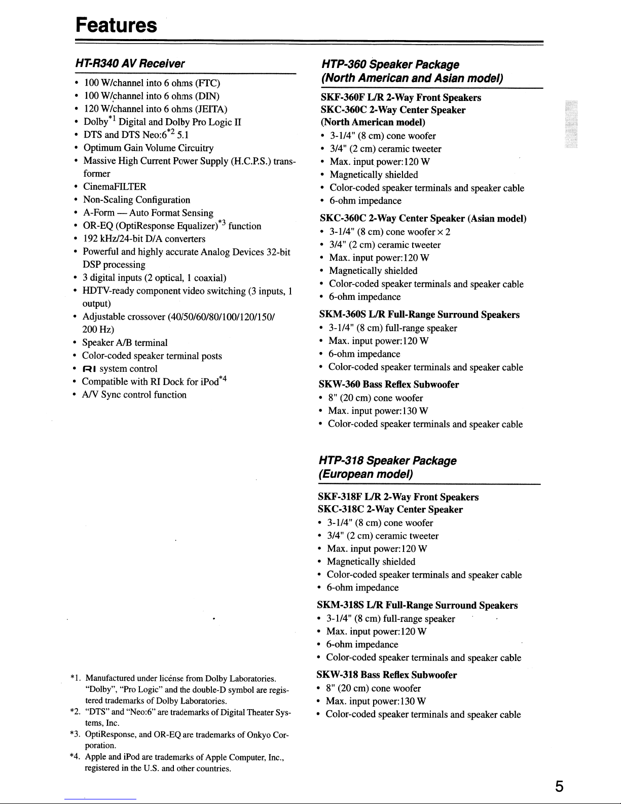
HT-R340
• 100 W/channe1 into 6 ohms
• 100 W/,channel into 6 ohms (DIN)
• 120 W/channel into 6 ohms (JEITA)
• Dolby*l Digital and Dolby Pro Logic
• DTS and DTS Neo:6*2 5.1
• OptimumGain Volume Circuitry
• Massive High Current Power Supply (H.C.P.S.) transformer
• CinemaFILTER
• Non-Scaling Configuration
• A-Form - Auto Format Sensing
• OR-EQ (OptiResponse Equalizer)*3 function
• 192 kHz/24-bit
• Powerful and highly accurate Analog Devices 32-bit
DSP processing
• 3 digital inputs (2 optical,
• HDTV-ready component video switching (3 inputs, 1
output)
• Adjustable crossover
200 Hz)
• SpeakerAlB terminal
• Color-coded speaker terminal posts
• R I system control
• Compatible with RI Dock for iPod*4
• A/V Sync control function
AV Receiver
D/A
converters
(40150/60/80/100/120/1501
(FfC)
II
I coaxial)
HTP-360 Speaker
Package
(North American and Asian model)
SKF·360F
SKC·360C 2-Way Center Speaker
(North American model)
•
3-114"
• 3/4" (2 em) ceramic tweeter
• Max. input power:120 W
• Magnetically shielded
• Color-coded speaker terminals and speaker cable
• 6-ohm impedance
SKC-360C 2-Way CenterSpeaker (Asian model)
• 3-1/4"(8em) cone woofer x 2
• 3/4" (2
• Max. input power:120 W
• Magnetically shielded
• Color-coded speaker terminals and speaker cable
• 6-ohm impedance
SKM-360S
• 3-1/4" (8 em) full-range speaker
• Max. input power:120 W
• 6-ohm impedance
• Color-coded speaker terminals and speaker cable
SKW·360 Bass Reflex Subwoofer
•
8"
• Max. input power: 130 W
• Color-coded speaker terminals and speaker cable
IJR
2·Way
Front
(8 em) cone woofer
em)
ceramic tweeter
IJR
Full-Range Surround Speakers
(20 em) cone woofer
Speakers
*
1.
Manufactured under license from Dolby Laboratories.
"Dolby", "Pro Logic" and the double-D symbol are registered trademarks
*2.
"DTS" and "Neo:6" are trademarksofDigital Theater Systems, Inc.
*3.
OptiResponse, and OR-EQ are trademarksofOnkyo Corporation.
*4.
Apple and iPod are trademarksofApple Computer, Inc.,
registered in the U.S. and other countries.
of
Dolby Laboratories.
HTP-318 Speaker
Package
(European model)
SKF·318F
SKC·318C 2·Way Center Speaker
•
3-114"
• 3/4" (2 em) ceramic tweeter
• Max. input power:120 W
• Magnetically shielded
• Color-coded speaker terminals and speaker cable
• 6-ohm impedance
SKM-318S LIR Full-Range Surround Speakers
• 3-1/4" (8
• Max. input power: 120 W
• 6-ohm impedance
• Color-coded speaker terminals and speaker cable
SKW·318 Bass Reflex Subwoofer
•
8"
• Max. input power: 130W
• Color-coded speaker terminals and speaker cable
IJR
2·Way
(8 em) cone woofer
em)
full-range speaker
(20 em) cone woofer
Front
Speakers
5
Page 6
Contents
Important Safety Instructions 2
Precautions 3
Speaker Precautions 4
Features 5
Package Contents 6
Front
Speaker Package
Remote Controller 12
Before Using the AV
Enjoying Home Theater 20
Connecting Your Speakers
Connecting Antenna 24
Connecting Your Components 26
& Rear Panels 8
receiver 19
11
21
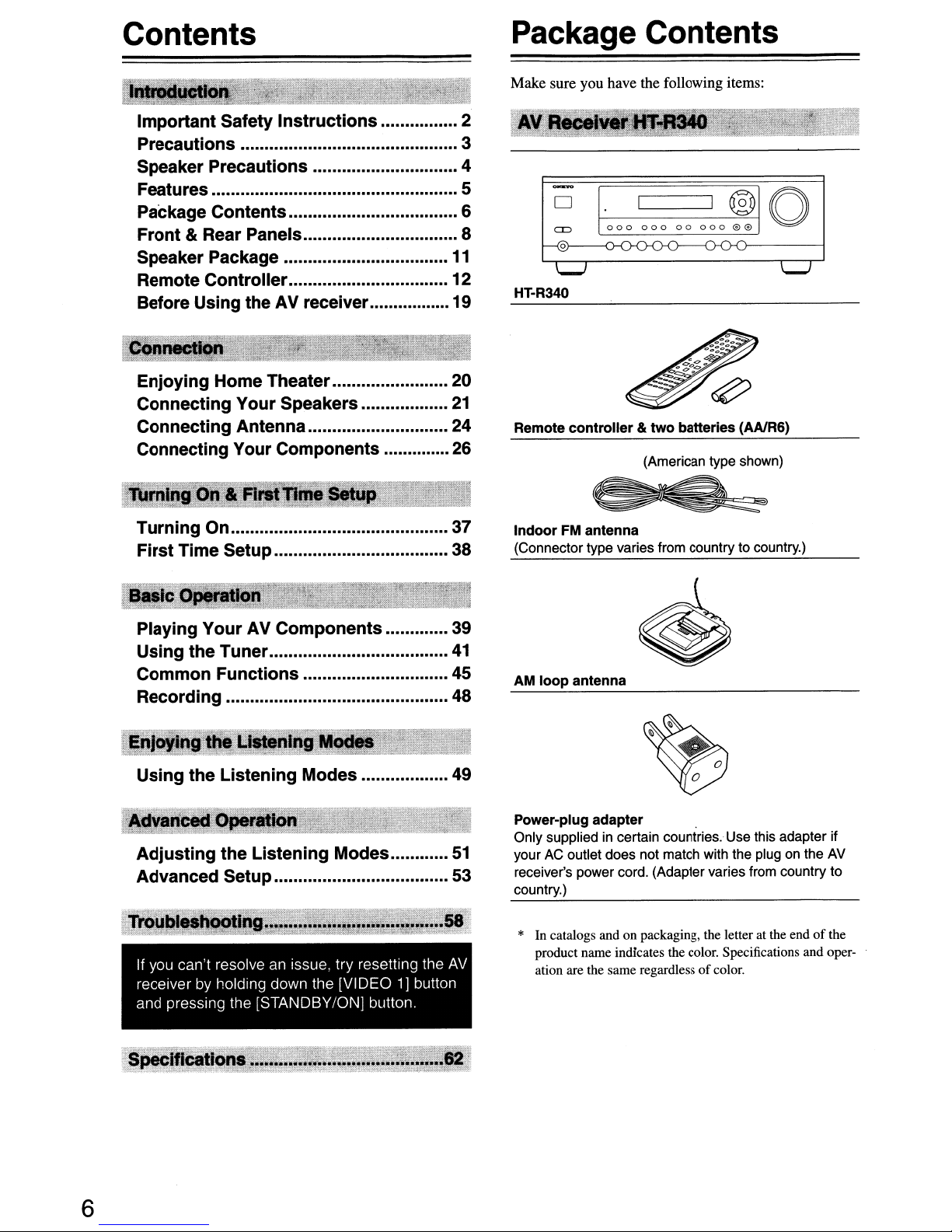
Package Contents
Make sure you have the following items:
~
0
=
L@
'I.-J
HT-R340
Remote controller
I I
000
000
00
~~~~
~~~~
&two batteries (AAJR6)
(American type shown)
000
-0-0
®
ee
()
'I.-J
Turning On 37
First Time Setup 38
Playing Your AV Components 39
Using the Tuner
41
Common Functions 45
Recording 48
Using the Listening Modes 49
If you can't resolve
receiverbyholding down the [VIDEO1]button
and pressing the [STANDBY/ON] button,
an
Issue, try resetting the
AV
Indoor FM antenna
(Connector type varies from country to country.)
AM loop antenna
Power-plug adapter .
Only supplied in certain countries. Use this adapter if
your AC outlet does not match with the plug on the AV
receiver's power cord. (Adapter varies from country to
country.)
*
In
catalogs and on packaging, the letter at the endofthe
product name indicates the color. Specifications and oper-
of
ation are the same regardless
color.
6
Page 7
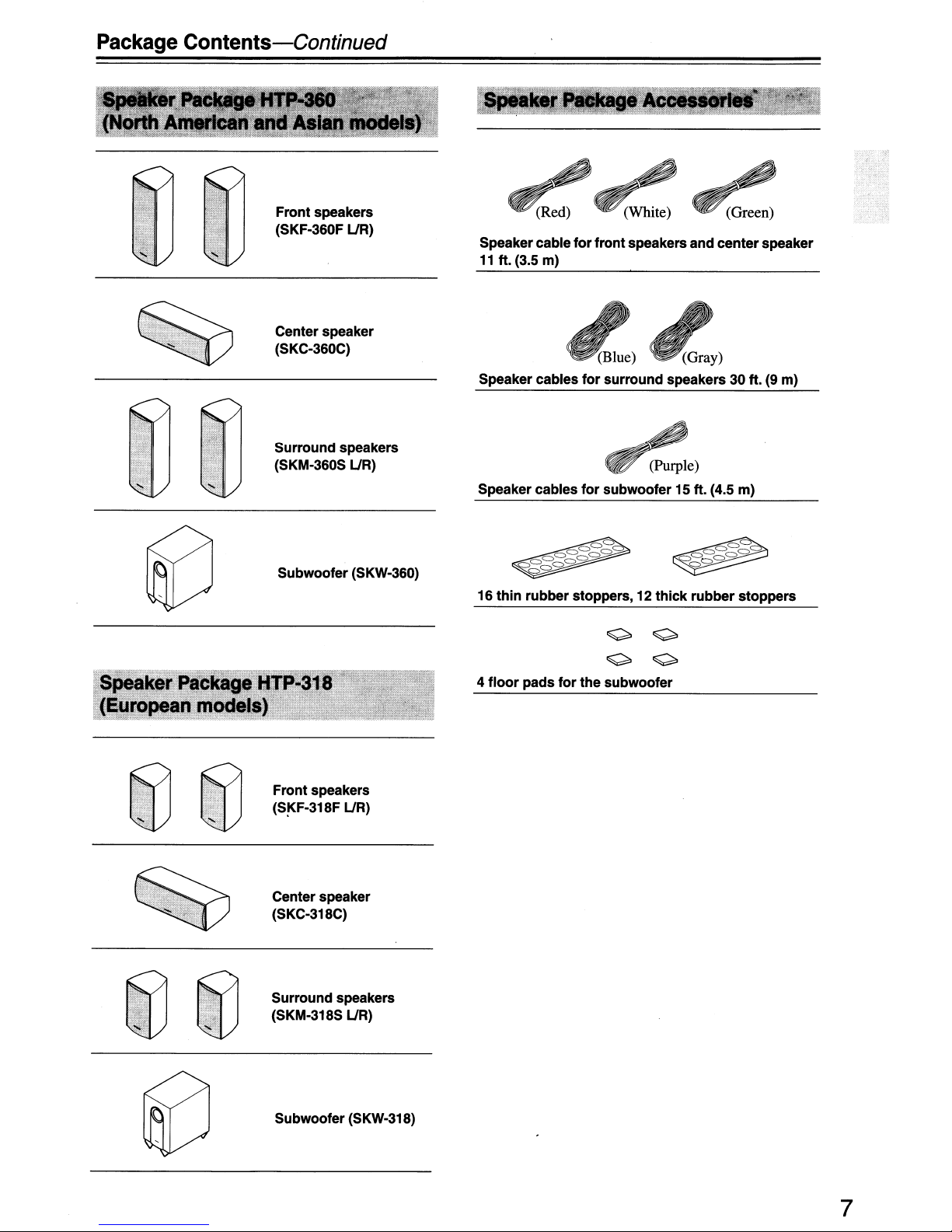
Package
Contents-Continued
Front speakers
(SKF·360F
Center speaker
(SKC·360C)
Surround speakers
(SKM·360S UR)
UR)
Speakercable
11
ft. (3.5 m)
Speaker cables
Speaker cables
for
frontspeakers and center speaker
(Blue) (Gray)
for
surround speakers 30 ft. (9 m)
(Purple)
for
subwoofer
15
ft. (4.5 m)
Subwoofer(SKW·360)
Front speakers
(S~F·318F
Center speaker
(SKC·318C)
Surround speakers
(SKM·318S UR)
UR)
16
4
==
0=
~
thin
rubber stoppers,12thick rubber stoppers
o 0
o 0
floor
pads
for
the subwoofer
=
==
Subwoofer (SKW·318)
7
Page 8
Front &Rear Panels
North American
European Models
and
Asian Models
ONKYO
"""
QOO
@,}--------i
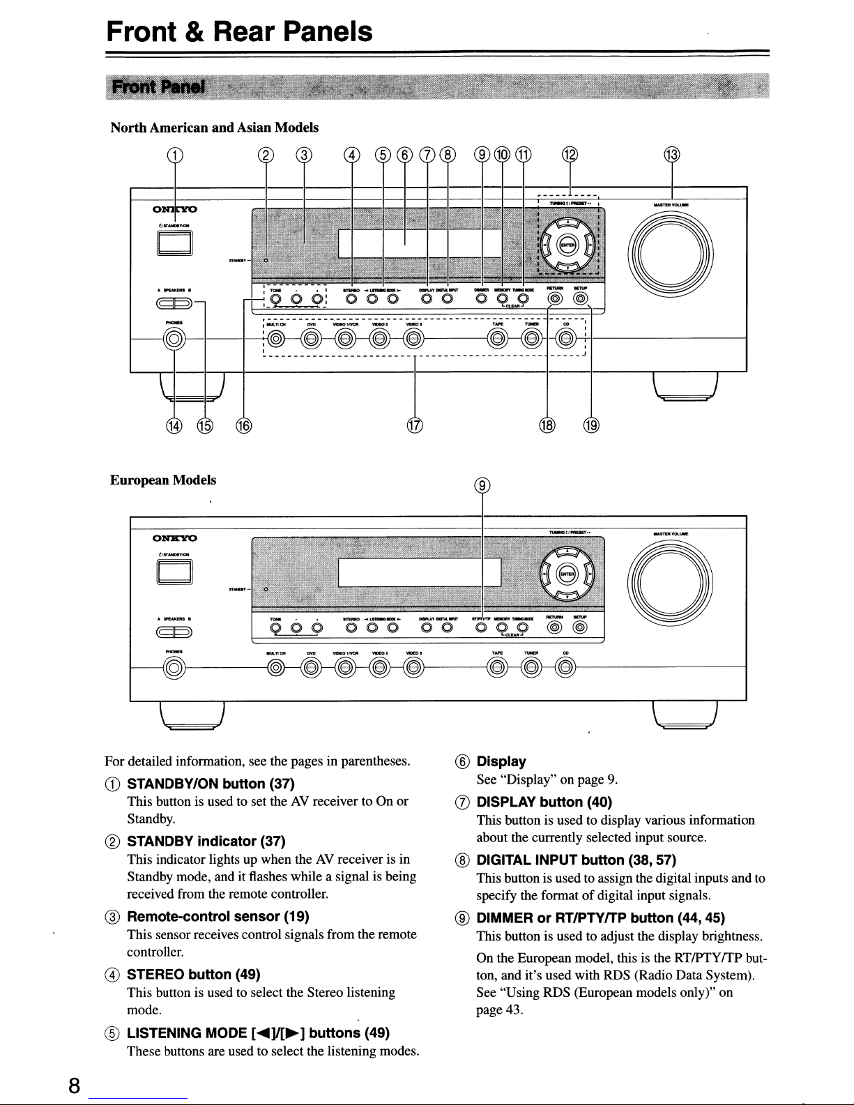
For detailed information, see the pages in parentheses.
CD
STANDBY/ON button (37)
This button is used to set theAVreceiver to On or
Standby.
® STANDBY
This indicator lights up when theAVreceiver is in
Standby mode, and it flashes while a signal is being
received from the remote controller.
@ Remote-control
This sensor receives control signals from the remote
controller.
@ STEREO
This button is used to select the Stereo listening
mode.
® LISTENING MODE
These buttons are used to select the listening modes.
indicator
button
(37)
sensor
(49)
(19)
[~]I[~]
buttons
(49)
a
® Display
See "Display" on page
(J)
DISPLAY
This button is used to display various information
about the currently selected input source.
button
® DIGITAL INPUT
This button is used to assign the digital inputs and to
specify the format
® DIMMER
This button is used to adjust the display brightness.
On the European model, this is the
ton, and it's used with RDS (Radio Data System).
See "Using RDS (European models only)" on
page 43.
or
RTIPTYITP
9.
(40)
button
of
(38, 57)
digital input signals.
button
(44,45)
RTlPTyrrp
but-
8
Page 9
Front&Rear
Panels-Continued
@ MEMORY button (42)
This button is used when storingordeleting radio
presets.
@ TUNING MODE button (41)
This
button is used to select the AutoorManual tun-
ingmode.
@ ArrowlTUNINGlPRESET & ENTER buttons
(51,53-56)
When
the
AMorFM
TUNING
tuner, and the
to select radio presets (see pages 41, 42).
setup menus are used, they
and
button is also used with the setup menus.
[A]
are used to select and set items.
@ MASTER VOLUME control (39)
This control is usedtoadjust the volumeofthe
receiver.
input
sourceisselected, the
[T]
buttons are used to tune the
PRESET[.....
]
[~]
work
buttons are used
When
as arrow buttons
The
ENTER
AV
the
@ PHONES jack (45)
This
114-inch phone
dard
pairofstereo headphones for private listening.
jack
is for connecting a stan-
@ SPEAKERS A & B buttons (39)
These
buttons are used to turn speaker sets A
onoroff.
@ TONE,
These
@ Input selector buttons
These
input
VIDEO2,VIDEO
The
multichannel input.
@)
RETURN button (51, 53, 54, 56)
This
played
@)
SETUP button (51,
This
[-]
&
[+]
buttons (45)
buttons are used to adjust the
(38-40)
buttons are used to select from
sources: MULTI CH, DVD,
3, TAPE,
[MULTI CH]
button is used to returntothe previously dis-
setup menu.
button is used to access various settings.
button
TUNER,orCD.
selects the
53-56)
bass
the
VIDEO
DVD
and
and
treble.
following
INCR,
analog
B
.....
.....
.....
iliff
.....
iEffi
••••• ••••• ••••• ••••• ••••• ••••• •.••• ••••• ••••• ••••• ••••• ••••• ••••• ••••• ••••• h
iiiii
fifi:
.....
fiiff
.....
.....
fiiff
ii:::
5
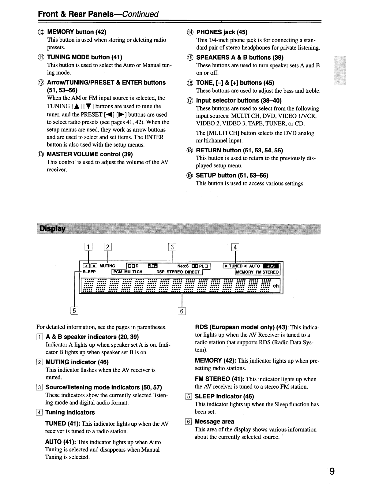
For detailed information, see the pages in parentheses.
IJJ
A & B speaker indicators (20, 39)
IndicatorA lights up
cator B lightsupwhen
[I]
MUTIN~
This indicator flashes when theAVreceiver is
muted.
indicator (46)
when
speaker set A is on. Indi-
speaker set B is on.
WSource/listening mode indicators (50, 57)
These
indicators
ing
mode
I1J
Tuning indicators
TUNED (41):
receiver is tuned to a radio station.
AUTO (41): This indicator lights up when Auto
Thning is selected
Thning is selected.
s~ow
the currently selected listen-
and digital audio format.
This
indicator lights up when the
and
disappears when Manual
AV
fiiff
ifj::
iEiii
RDS (European model only) (43):
tor lightsupwhen
radio station that supports
tem).
MEMORY (42): This
setting radio stations.
FM STEREO (41): This indicator lights
theAVrecejver is tuned to a stereoFMstation.
rn
SLEEP indicator (46)
This
been
[§] Message area
This areaofthe display shows various information
about the currently selected source
. .
. .
iffi!
fiiii
ifi::
iij:!
filii
theAVReceiver is
RDS
indicator
indicator lightsupwhen the
set.
C
This
tunedtoa
(Radio
Data
lightsupwhen
up
Sleep
function has
..
indica-
Sys-
pre-
when
9
Page 10
Front & Rear Panels-Continued
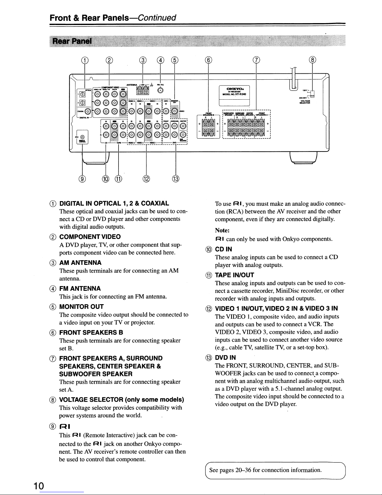
CD
DIGITAL IN OPTICAL 1, 2 & COAXIAL
These optical and coaxial jacks canbeused to con-
or
nect a CD
with digital audio outputs.
®
COMPONENT
A DVD player,
ports component video can be connected here.
DVD player and other components
VIDEO
TV,
or other component that sup-
@ AM ANTENNA
These push terminals are for connecting an AM
antenna.
@
FMANTENNA
This jack is for connecting an PM antenna.
® MONITOR
The composite video output should be connected to
a video input on your TV or projector.
OUT
® FRONT SPEAKERS B
These push terminals are for connecting speaker
set B.
(J)
FRONT
SPEAKERS, CENTER SPEAKER &
SUBWOOFER
These push terminals are for connecting speaker
setA.
® VOLTAGE SELECTOR (only
This voltage selector provides compatibility with
power systems around the world.
SPEAKERS A,
SPEAKER
SURROUND
some
models)
To
use R I , you must make an analog audio connec-
AV
tion (RCA) between the
if
component, even
Note:
R I can only be used with Onkyo components.
@CDIN
These analog inputs can be used to connect a
player with analog outputs.
they are connected digitally.
receiver and the other
® TAPE IN/OUT
These analog inputs and outputs can be used to connect a cassette recorder, MiniDisc recorder, or other
recorder with analog inputs and outputs.
@ VIDEO 1 IN/OUT, VIDEO 2 IN & VIDEO 3
The VIDEO I, composite video, and audio inputs
and outputs can be used to connect a VCR. The
VIDEO 2, VIDEO 3, composite video, and audio
inputs can be used to connect another video source
TV,
(e.g., cable
@
DVDIN
The FRONT, SURROUND, CENTER, and SUBWOOFER jacks can be used to connect.a component with an analog multichannel audio output, such
as a DVD player with a S.l-channel analog output.
The composite video input should be connected to a
video output on the DVD player.
satellite
TV,
or a set-top box).
CD
IN
®
r-U
This
RI
(Remote Interactive) jack can be con-
nected to the
nent. The
be used to control that component.
10
R I jack on another Onkyo compo-
AV
receiver's remote controller can then
See pages
20-36
for connection information.
Page 11
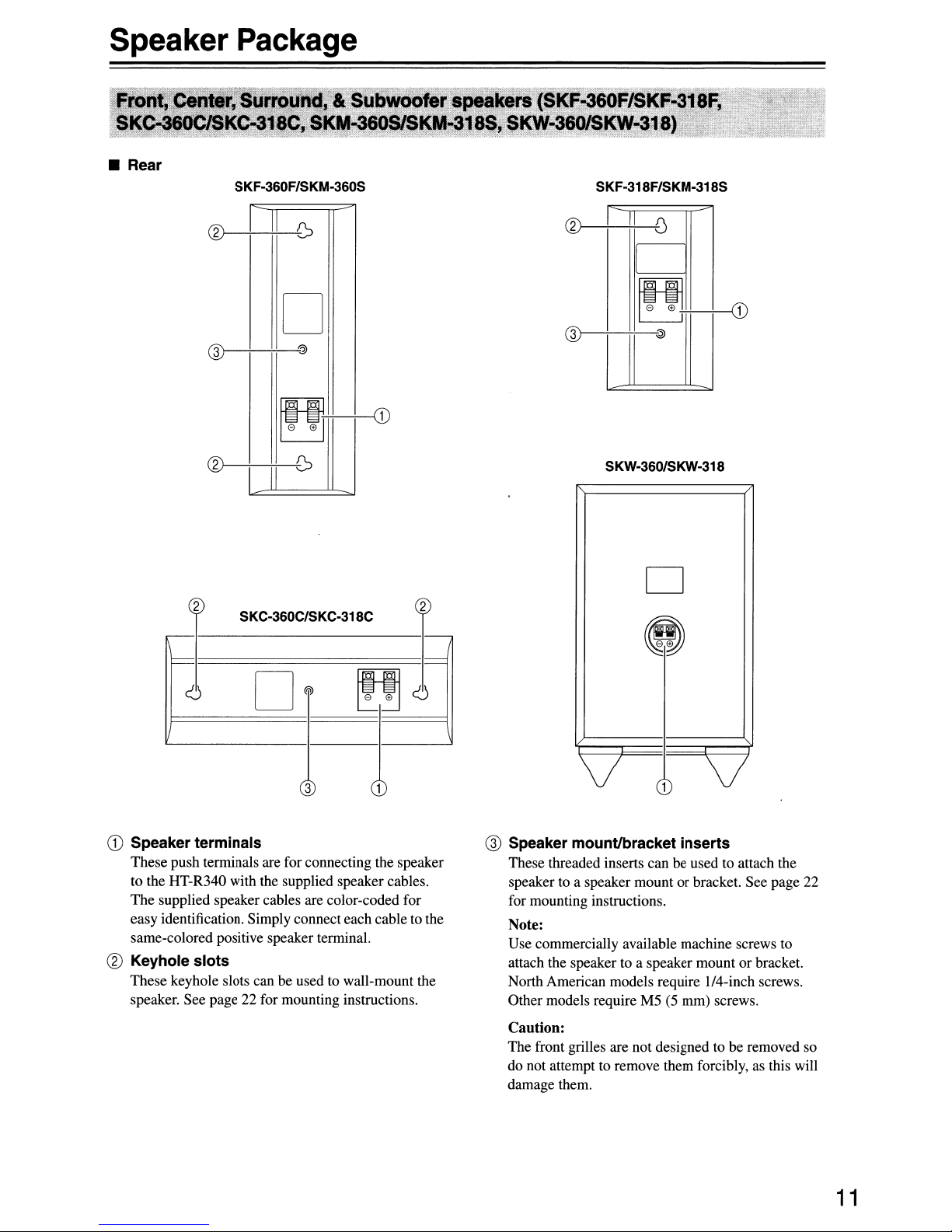
Speaker Package
• Rear
SKF-360F/SKM-360S
SKF-318F/SKM-318S
0>
D
@
SKC-360C/SKC-318C
[)
(1)
e
SKW-360/SKW-318
D
@
~
~
CD
Speaker terminals
These push tenninals are for connecting the speaker
to the HT-R340 with the supplied speaker cables.
The supplied speaker cables are color-coded for
easy identification. Simply connect each cable to the
same-colored positive speaker tenninal.
® Keyhole slots
These keyhole slots can be used to wall-mount the
speaker. See page 22 for mounting instructions.
D®
3
~~
i
~
@ Speaker mountlbracket inserts
v
These threaded inserts can be used to attach the
speaker to a speaker mount
for mounting instructions.
Note:
Use commercially available machine screws to
attach the speaker to a speaker mount
North American models require 1I4-inch screws.
Other models require M5
Caution:
The front grilles are not designed to be removed so
do not attempt to remove them forcibly, as this will
damage them.
v
or
bracket. See page 22
or
(5
mm) screws.
bracket.
11
Page 12
Remote Controller
AV
Including the
used to control up to six different components. The
remote controller has a specific operating mode for use
with each type
using the five REMOTE
• RECEIVERITAPE Mode
In
RECEIVERffAPEmode, you cancontrol
the
AV
receiver and an Onkyocassette
recorder connected via
•
DVD,
CD,
Withthese modes, you cancontrol an Onkyo
DVD player and CD/MD/CDR/HDD
player/recorder.
receiver, the remote controller can be
of
component. Modes are selected by
MD,
CDR&HOD
MODE
R I.
buttons.
Modes
[Irmrsl]
TAPE
[I
DVD
[ICDI]
[IMDI]
[I
CDR
(I
HOD
Use the
a mode.
Use the buttons supported by that mode
to
Note:
Someofthe remote controller operations described in
this manual may not work as expected with other components.
REMOTE
control the component.
RECEIVER mode: see right column
MD/CDR mode: see page 16
MODE buttonstoselect
DVD mode: see page 14
CD mode: see page 15
HDD mode: see page 17
TAPE mode: see page 18
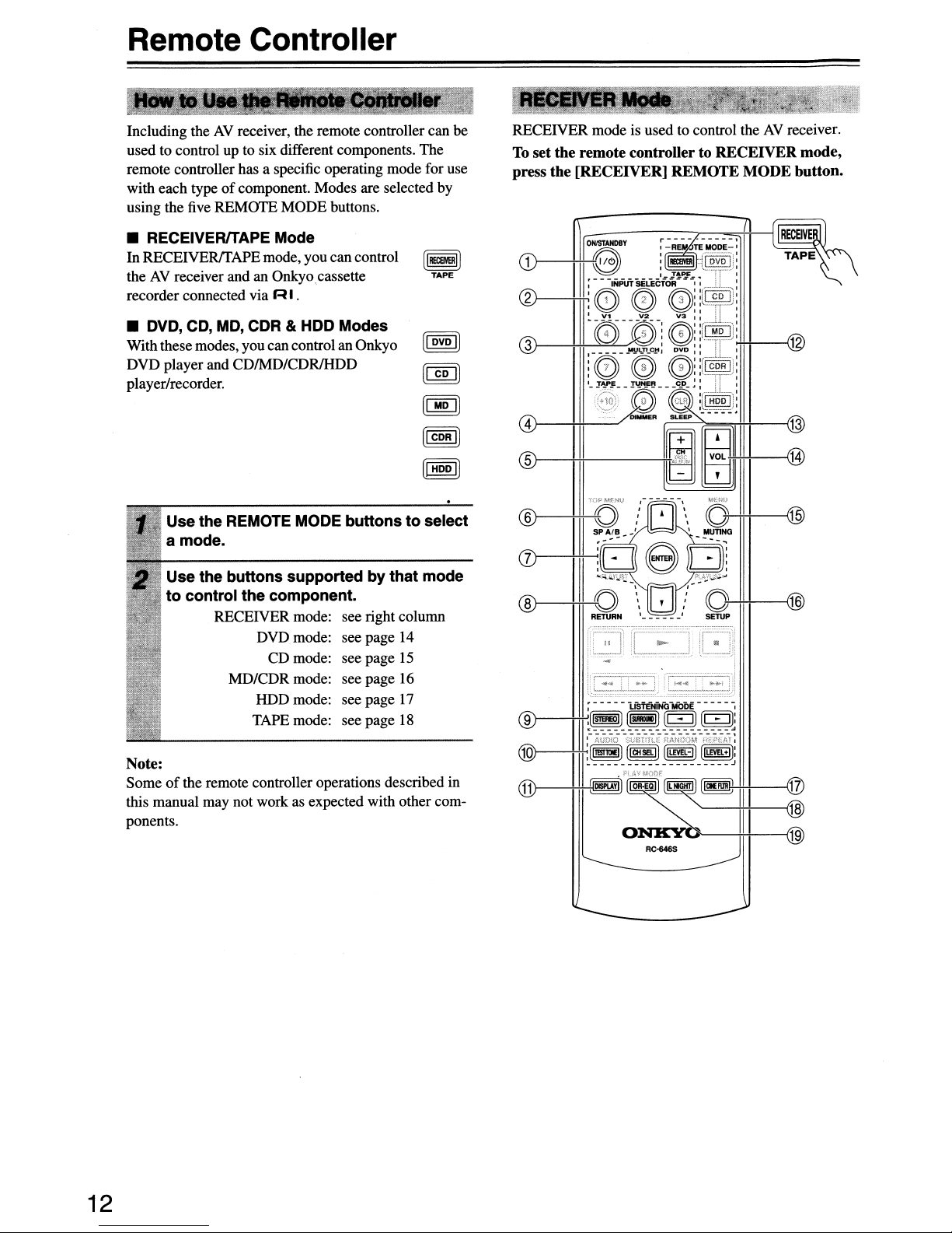
RECEIVER mode is used to control theAVreceiver.
To
set the remote controller to RECEIVER mode,
press the [RECEIVER] REMOTE MODE button.
I]
I]
I]
(1)--+1
®--++f---~
9
@)
@
++-------"'11
;-----L~fE~NG-MbDE-----,
)--+1II~1
,i=~_~~=~
:(l1lSTlaE!]
~~;~-O~-~f~-£~~~
[laiSEL!]
(iL£VEL-I]
[!LEVEL-I):
11~'ij'~~-f+-tlil-----\~
ONK'Yb--~III---{19
RC-646S
12
Page 13

Remote Controller-Continued
For detailed information, see the pages in parentheses.
CD
ON/STANDBY button (37)
This button is used to set theAVreceiver to On or
Standby.
® INPUT SELECTOR buttons (39)
These buttons are used to select the input sources.
@)
MULTI CH button (40)
This buttonisused to select the multichannel DVD
input.
@ DIMMER button (45)
This button is used to adjust the display brightness.
@)
CH
+/-
button (42)
This button is used to select radio presets.
® SP AlB button (39)
This button is used to
or off.
(j) Arrow
(51,53-56)
These buttons are used to select and adjust settings.
["]I[~]I[""]I[~]
tum
speaker sets A and B on
&ENTER buttons
® RETURN button (51, 53, 54, 56)
This button is usedtoreturn to the previous display
when changing settings.
® LISTENING MODE buttons (49)
These buttons can be used to select listening modes
regardless
ler mode.
STEREO button
This button selects the Stereo
SURROUND button
This button selects the Dolby and DTS listening
modes.
[
....
These buttons can be used to select anyofthe avail-
able listening modes.
@)
TESTTONE, CH SEL, LEVEL· & LEVEL+
buttons (37, 47, 54)
These buttons are used to adjust the levelofeach
speaker.
@ DISPLAY button (40)
This button is used to display various information
about the currently selected input source.
@ REMOTE MODE buttons (12)
These buttons are used to select the remote controller modes. When you press a button on the remote
contr911er,
rently selected mode lights up.
@ SLEEP button (46)
This button is used to set the Sleep function.
@)
VOL
This button can be used to adjust the volumeofthe
AV
remote controller mode.
of
the currently selected remote control-
Mstening
]I[~]
buttons
the REMOTE MODE button for the cur-
["]I[~]
receiver regardlessofthe currently selected
button (39)
mode.
@ MUTING button (46)
This button is used to mute theAVreceiver.
@ SETUP button (51,
This buttonisused to access various settings.
53-56)
® CINE FLTR button (52)
This buttonisused to set the CinemaFILTER function.
@ L NIGHT button (52)
This button is used to set the Late Night function.
@)
OR·EQ button (46)
This button is used to turn on the OptiResponse
Equalizer, which optimizes performance when the
HT-R340 is used with the speakers included in the
HTP-360IHTP-318 Home Theater Speaker Package. When the OptiResponse Equalizer is on, you
can enjoy a powerful sound with movies or music
even at low volume levels.
13
Page 14
Remote
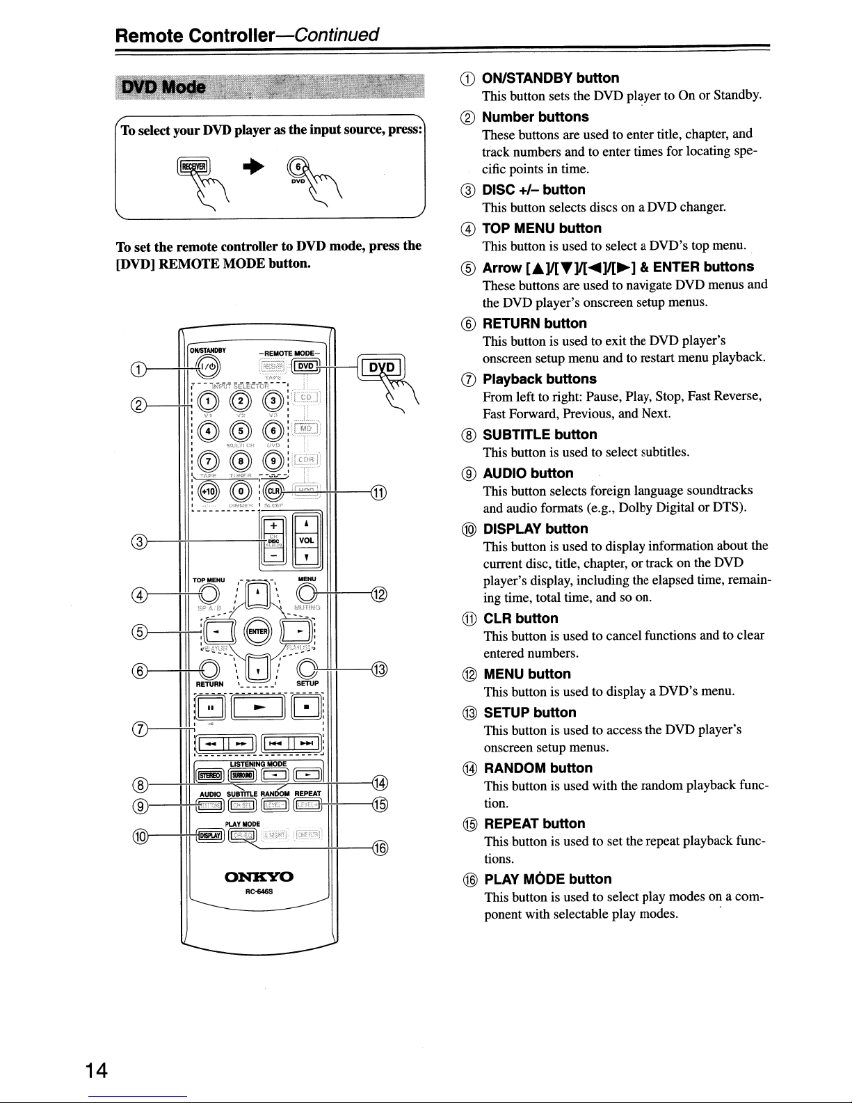
To
select your DVD player as the
set
To
[DVD]
Controller-Continued
the
remote controller to DVD mode, press the
REMOTE
MODE button.
ONKYO
RC-646S
input
source, press:
CD
ON/STANDBY
This button sets the DVD player to On or Standby.
® Number
These buttons are used to enter title, chapter, and
track numbers and to enter times for locating specific points in time.
@ DISC
@
(§)
+/-
This button selects discs on a DVD changer.
TOP
MENU button
This button is used to select a DVD's top menu.
Arrow
These buttons are used to navigate DVD menus and
the DVD player's onscreen setup menus.
[.]I[T]I[~]I[~]
® RETURN
This button is used to exit the DVD player's
onscreen setup menu and to restart menu playback.
(j)
Playback
From left to right: Pause, Play, Stop, Fast Reverse,
Fast Forward, Previous, and Next.
® SUBTITLE
This button is used to select subtitles.
® AUDIO
This button selects foreign language soundtracks
and audio formats (e.g., Dolby Digital or DTS).
@)
DISPLAY button
This button is used to display information about the
current disc, title, chapter, or track on the DVD
player's display, including the elapsed time, remaining time, total time, and so on.
@ CLR
This button is used to cancel functions and to clear
entered numbers.
@
MENU
This button is used to display a DVD's menu.
@ SETUP
This button is used to access the DVD player's
onscreen setup menus.
@ RANDOM
This button is used with the random playback func-
tion.
button
button
button
button
button
buttons
button
button
buttons
button
button
& ENTER
buttons
@ REPEAT button
This button is used to set the repeat playback functions.
@ PLAY MODE button
This button is used to select play modes on a component with selectable play modes. .
14
Page 15
Remote
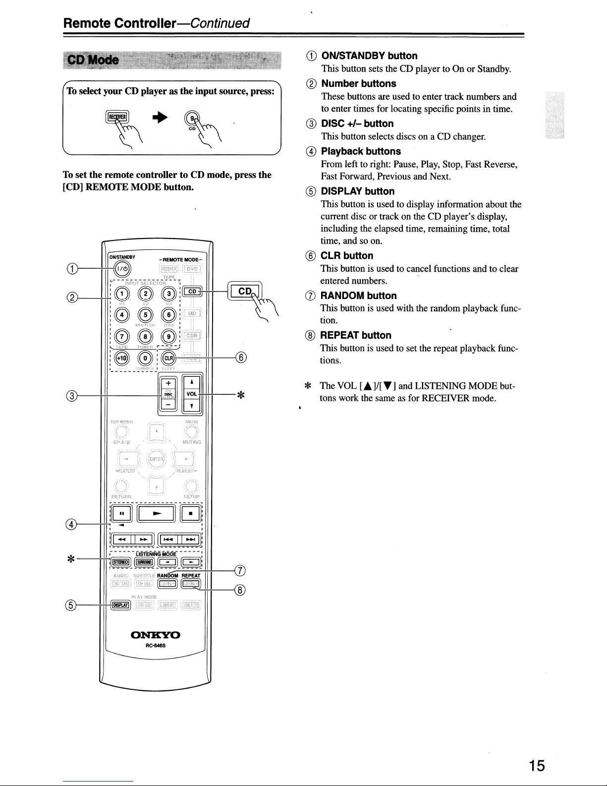
To select
To
set
the
[CD]
REMOTE
Controller-Continued
yourCDplayerasthe
remote
controllertoCD
MODE
button.
input
source, press:
mode,
press
the
CD
ON/STANDBY
This button sets the CD player toOnor
®
Number
These buttons are used to enter track numbers and
to enter times for locating specific points in time.
@
DISC
+/-
This button selects discs on a CD changer.
@
Playback
From left to right: Pause, Play, Stop, Fast Reverse,
Fast Forward, Previous and Next.
®
DISPLAY
This button is used to display information about the
current disc or track on the
including the elapsed time, remaining time, total
time, and so on.
®
CLR
button
This button is used to cancel functions and to clear
entered numbers.
(J)
RANDOM
This button is used with the random playback function.
®
REPEAT
This button is used to set the repeat playback func-
tions.
button
buttons
button
buttons
button
button
button
CD
player's display,
Standby.
ONKYO
RC-646S
* The VOL
tons work the same as for RECEIVER mode.
[.J/[TJ
and LISTENING
MODE
but-
15
Page 16

Remote Controller-Continued
To select your MiniDiscorCD recorder as the
source, press:
~
* You must change the Input Display (see page 38).
To set
the
press
the
..
~
remote controller to
[MO]or[CDR]
REMOTE
MD or
CD
recorder
MOorCDR
MODE
input
mode,
button.
CD
ON/STANDBY button
This button sets the MD/CD recorder to On or
Standby.
® Number buttons
These buttons are used to enter track numbers and
to enter times for locating specific points in time.
The[+10] button is used to enter numbers above 10.
@ Playback buttons
From left to right: Pause, Play, Stop, Fast Reverse,
Fast Forward, Previous and Next.
@ DISPLAY button
This button is used to display information about the
current discortrack on the MD/CD recorder's display, including the elapsed time, remaining time,
total time, and so on.
@)
CLR button
This button is used to cancel functions and to clear
entered numbers.
® RANDOM button
This button is used with the random playback function.
(j)
REPEAT button
This button is used to set the repeat playback functions.
® PLAY MODE button
This button is used to select play modes on a component with selectable play modes.
ONKYO
RC+I6S
* The VOL
tons work the same as for RECEIVER mode.
[.]/[
....] and LISTENING MODE but-
16
Page 17
Remote Controller-Continued
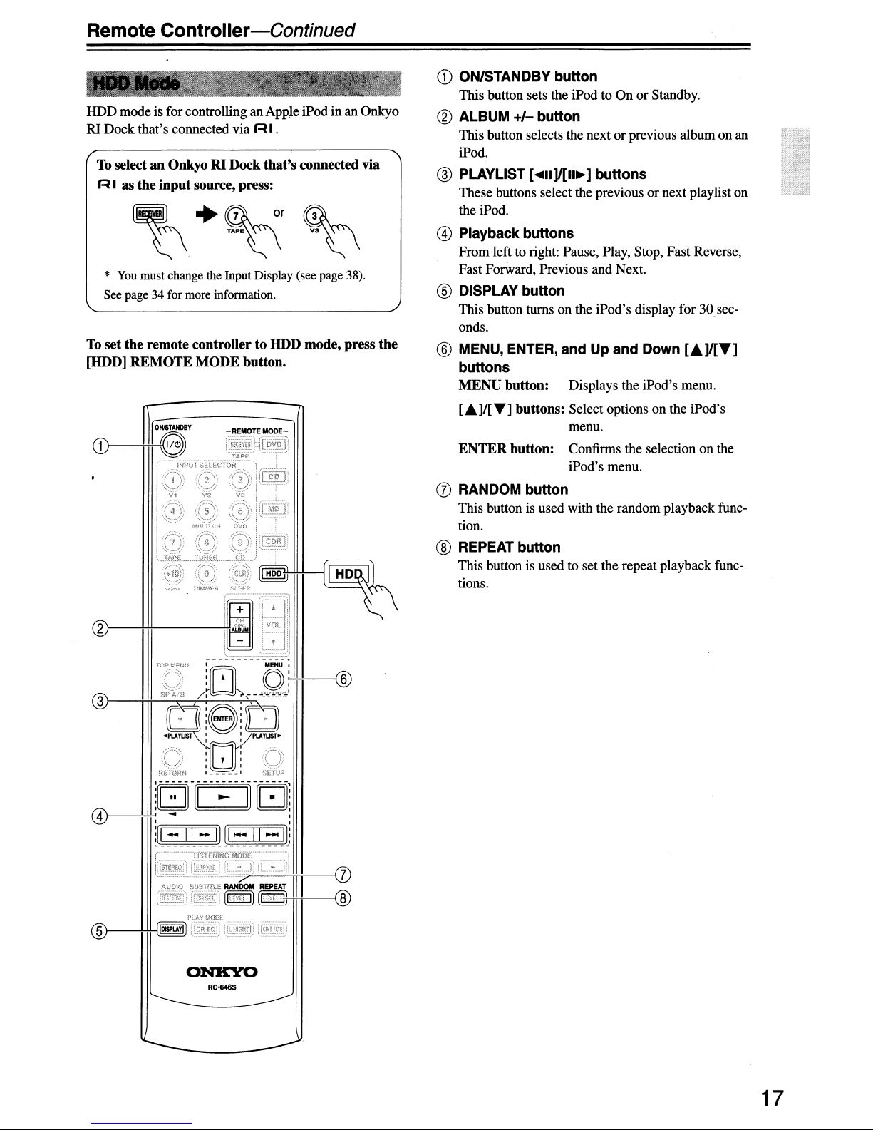
HDD mode is for controlling an Apple iPod in an Onkyo
RI Dock that's connected via
To select an Onkyo RI Dock
R I
as
the
input
source, press:
*
You
must change the Input Display (see page 38).
See page 34 for more information.
To
set
the
[HOD]
remote
REMOTE
controllertoHDD mode, press
MODE
RI.
that's
button.
connected via
the
CD
ON/STANDBY button
This button sets the iPod to On or Standby.
® ALBUM
This button selects the nextorprevious album on an
iPod.
@ PLAYLIST [
These buttons select the previous or next playlist on
the iPod.
+/-
button
....
II]/[II~]
buttons
@ Playback buttons
From left to right: Pause, Play, Stop, Fast Reverse,
Fast Forward, Previous and Next.
® DISPLAY button
This button turns on the iPod's display for30seconds.
® MENU, ENTER, and Up
buttons
MENU
button:
Displays the iPod's menu.
and
Down
[.A]/[T]
®
["']I[T]
ENTER
buttons: Select options on the iPod's
menu.
button:
Confirms the selection on the
iPod's menu.
(j) RANDOM button
This button is used with the random playback function.
® REPEAT button
This button is used to set the repeat playback functions.
51---+H--I
ONKYO
RC-646S
17
Page 18

Remote Controller-Continued
To select
press:
TAPE mode is used to control an Onkyo cassette
recorder connected to the
To
[RECEIVER]
For twin cassette decks, only deck B canbecontrolled.
set
the
your
remote
REMOTE
Cassette
deckasthe
AV
receiver via R I.
controllertoTAPE
MODE
input
mode,
button.
source,
press
the
CD
Play
[~]
button
This button is used to start playback.
® Stop
@ Reverse Play [
@ Rewind & FF [
[.]
button
This button is used to stop playback.
.....
]
button
This button is used to start reverse playback.
...
]I[~]
buttons
TheRewind [
FF
[~]
...
] buttonis used to start rewind. The
button is used to start fast forward.
)}
::,...J:
'iILPUST!"
"'1"'1:/
f'\
~Jt-~
ONKYO
RC-648S
18
4
Page 19
Before Using the AV receiver
,::"",
,-".,.;-
'.
-
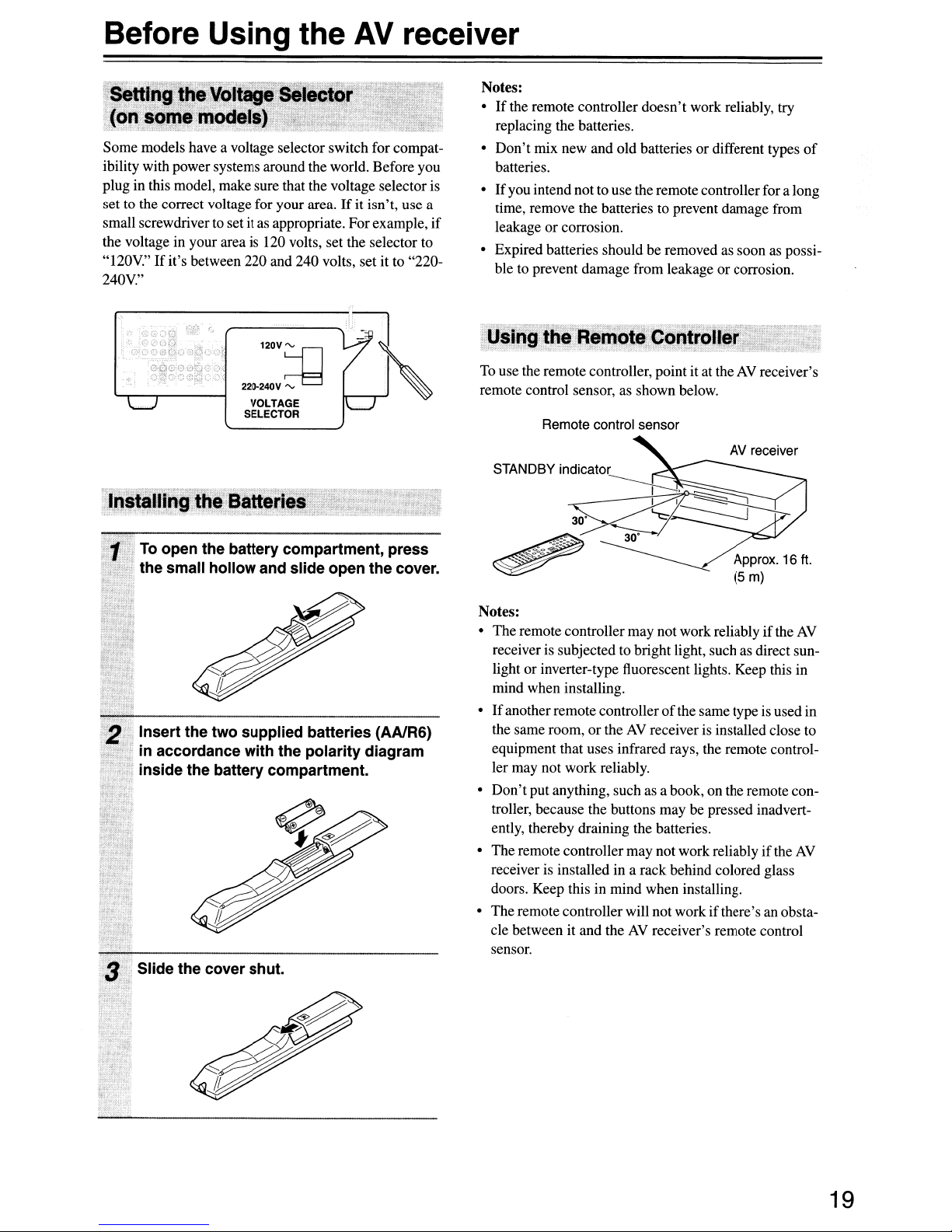
setting
(on
Some models have a voltage selector switch for compatibility with power systems around the world. Before you
plug in this model, make sure that the voltage selector is
set to the correct voltage for your area.
small screwdriver to set it
the voltage in your area
"120V."
240V."
th.e
Voltage
somemodels).'
. .
.--=-:,y
If
it's between 220 and 240 volts, set it to "220-
Selector
as
appropriate. For example, if
is
120 volts, set the selector to
:".
.,
.:;
If
it isn't, use a
Notes:
•
If
replacing the batteries.
• Don't mix new and old batteries or different types
batteries.
•
If
time, remove the batteries to prevent damage from
leakage or corrosion.
• Expired batteries should be removed as soon as possible to prevent damage from leakage or corrosion.
the remote controller doesn't work reliably, try
of
you intend notto use the remote controller for a long
""~
,~,~,;Q
VOLTAGE
SELECTOR
InstaUingriheBatteries
. '
~
. ;
1
To
open the battery compartment, press
the small hollow and slide open the cover.
"~
j'
.
2 Insert the two supplied batteries (AAlR6)
."
in accordance with the polarity diagram
inside the battery compartment.
Slide the cover shut.
To
use the remote controller, point it at theAVreceiver's
remote control sensor, as shown below.
Remote control sensor
AV receiver
Approx.
(5 m)
Notes:
• Theremote controller may not work reliably if the AV
receiver is subjected to bright light, such as direct sun-
light or inverter-type fluorescent lights. Keep this in
mind when installing.
•
If
anotherremote controllerofthe same type is used in
or
the same room,
equipment that uses infrared rays, the remote controller may not work reliably.
• Don'tput anything, such as a book, on the remote controller, because the buttons may be pressed inadvertently, thereby draining the batteries.
The remote controller may not work reliably
receiver is installed in a rack behind colored glass
doors. Keep this in mind when installing.
• The remote controller will not work ifthere's an obstacle between it and the
sensor.
theAVreceiver is installed close to
AV
receiver's remote control
ifthe
16
ft.
AV
19
Page 20
Enjoying HomeTheater
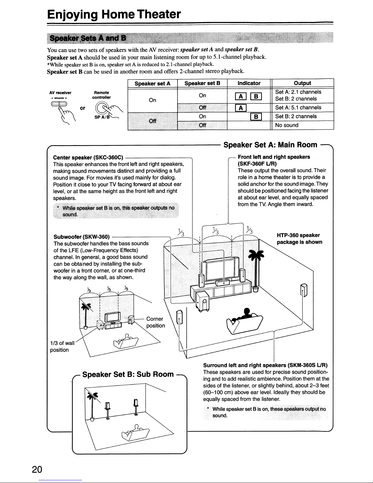
You can use two setsofspeakers with theAVreceiver: speaker setA and speaker set B.
Speaker
*While speaker set B is on, speaker set A is reduced to 2. I-channel playback.
Speaker
setA
shouldbeused in your main listening room for up to 5.l-channel playback.
set
B canbeused in another room and offers 2-channel stereo playback.
AV
receiver
Remote
controller
~
Speaker
On
Off
set
A
.".
".------------------
Center
This speakerenhances the front left and right speakers,
making sound movements distinct and providing a full
sound image. For movies it's used mainly for dialog.
Position it close to your
level, or at the same height as the front left and right
speakers.
Subwoofer
The subwooferhandles the bass sounds
of the LFE (Low-Frequency Effects)
channel. In general, a good bass sound
can be obtained by installing the subwoofer in a front corner, or at one-third
the way along the wall, as shown.
speaker
~
-'31.,
.;:;""-
·wn;Ie.speakersetB
50000.'
(SKC-360C)
. ? _
(SKW-360)
---------,
TV
facing forward at about ear
"_
thiS
---------.,
'">
speakijri>utput5
'~:1~:
is.on,
",...
. "
no
•
Speaker
<
..
c·
'"
""oJ
On
Off
On
Off
set
B
•.
":'.
Indicator
0000
00
00
Set
Set
Set
Set
No sound
Speaker Set A: Main Room
Front
left
and
right
(SKF-360F
These output the overall sound.Their
role in a home theater is to provide a
solid anchorfor the sound image. They
shouldbe positioned facing the listener
at about ear level, and equally spaced
from the
UR)
TV.
Angle them inward.
HTP-360
packageisshown
Output
A:
2.1 channels
B:
2 channels
A:
5.1 channels
B:
2 channels
speakers
speaker
1/3 of wall
position
Speaker Set B: Sub Room
20
Corner
position
Surround
These speakers are used for precise sound positioning and to add realistic ambience. Position them at the
sides of the listener, or slightly behind, about
left
and
right
speakers
(SKM-360S UR)
2-3
feet
(60-100 em) above ear level. Ideally they should be
equally spaced from the listener.
Bis
• While speaker set
sound.
on, these speakers outputno
Page 21
Connecting
Your
Speakers
Read the following before connecting your speakers:
• You can connect speakers with an impedance
6
ohmsorhigher.Ifyou use speakers with a lower
impedance, and use the amplifier at high volume lev-
of
els for a long period
circuit may be activated.
• Disconnectthe power cord from the wall outlet before
making any connections.
• Pay close attention to speaker wiring polarity.
words, connect positive
(+) terminals, and negative
tive
(-)
terminals.Ifyou get them the wrong way
around, the sound will be out
unnatural.
• Unnecessarily long,
affect the sound quality and should
• Be careful not to short the
positive and negative wires.
Doing so may damage the
receiver.
Don't
•
•
connect more than one
cable to each speaker terminal. Doing so may damage the
AV
receiver.
Don't
connect one speaker to several terminals.
time, the built-in protection
(+) terminals to only positive
(-)
terminals to only nega-
of
phase and will sound
or
very thin speaker cables may
be
AV
avoided.
of
In
other
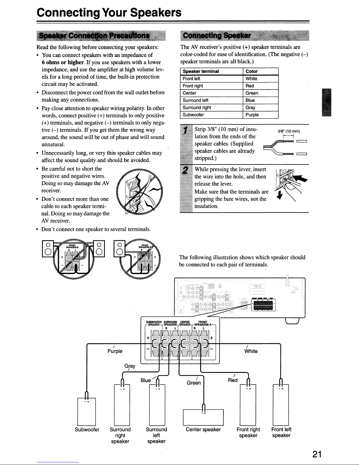
TheAVreceiver's positive (+) speaker terminals are
color-coded for ease
speaker terminals are all black.)
Speaker terminal Color
Front
left
Front
right
Center
Surround
Surround
Subwoofer
left
right
Strip 3/8" (10 mm)ofinsulation from the ends
speaker cables. (Supplied
speaker cables are already
stripped.)
While pressing the lever, insert
the wire into the hole, and then
release the lever.
Make sure that the terminals are "
gripping the bare wires, not the
insulation.
of
identification. (The negative
White
Red
Green
Blue
Gray
Purple
of
the
318'
<::
~
..
(10mm)
r-------l
(-)
I
The following illustration shows which speaker should
of
Red
/
terminals.
...
. .
. .
•
/
White
-+
"'!'"
-+
be connected to each pair
/
Purple
/
-+-+
-+
Green
C-'+~
Subwoofer Surround
right
speaker
Surround
left
speaker
Center speaker
Front right
speaker
Front left
speaker
21
Page 22
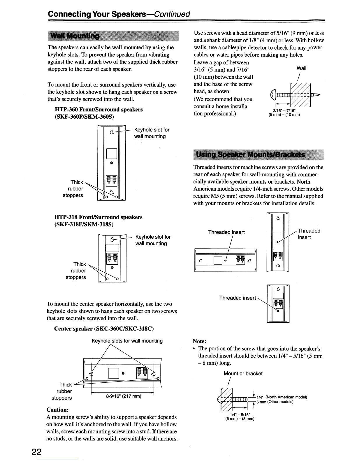
Connecting
The
speakers
keyhole slots. To prevent the speaker from vibrating
against the wall, attach two
stoppers to the rear
To mount the front
the keyhole slot shown to hang each speaker on a screw
that's securely screwed into the wall.
HTP-360 Front/Surround speakers
(SKF-360F/SKM-360S)
Your
can
easilybewall mounted by using the
of
or
Speakers-Continued
of
the supplied thick rubber
each speaker.
surround speakers vertically, use
Use screws with a head diameterof5/16" (9 mm)orless
of
and a shank diameter
walls, use a cable/pipe detector to check for any power
cables or water pipes before making any holes.
of
Leave a gap
3/16" (5 mm) and 7/16"
(10 mm) between the wall
and the base
head, as shown.
(We recommend that you
consult a home installation professional.)
between
of
the screw
1/8" (4 mm)orless. With hollow
Wall
/
._
.
--
.
~
I---
3116"
- 7/16"
(5 mm) - (10 mm)
~
Keyhole slot for
wall mounting
D
o
ThiCk~~
rubber ,
stoppers
HTP-318 Front/Surround speakers
(SKF-318F/SKM-318S)
Thick
rUbber~O
stoppers I
To mount the center speaker horizontally, use the two
keyhole slots shown to hang each speaker on two screws
that are securely screwed into the wall.
\)
,..----
'===
~
II
~
(';,
;)
~
~
Keyhole,slot for
wall mounting
Threadedinserts for machine screws are providedonthe
of
each speaker for wall-mounting with commer-
rear
cially available speaker mounts
American models require ll4-inch screws. Other models
require M5 (5 mm) screws. Refer tothe manual supplied
with your mounts or brackets for installation details.
Threaded insert
~~
D~~~
or
brackets. North
0
ill
D
;7iI1
~
~
0
Y Threaded
insert
o
Threaded insert
~
Center
stoppers
Caution:
A mounting screw's ability to support a speaker depends
on how well it's anchored to the wall.
walls, screw each mounting screw into a stud.
no studs, orthe walls are solid, use suitable wall anchors.
22
speaker (SKC-360C/SKC-318C)
Keyhole slots for wall mounting
Thick
rubber
rr
A3=1
D·
~:=:::=:==""'=:::::::::~===j==jl
8-9/16"
(217
mm)
If
you have hollow
If
there are
Note:
• The portionofthe screw that goes into the speaker's
threaded insert should
-8
mm) long.
Mount or bracket
be
between 1/4" - 5/16" (5 mm
/
~-~
~-t
1/4" - 5/16"
(5 mm) - (8 mm)
1/4" (North American model)
5 mm (01hermodels)
Page 23

Connecting
.....
-
Jo'._'.':
Uslng
.
More
We recommend using the provided rubber stoppers to
achieve the best possible sound from your speakers. The
rubber stoppers prevent the speakers from moving, providing a more stable platform. Use thick stoppers for the
center speaker, and thin stoppers for the other speakers.
9 i
;:..--'!t
theflubber Stoppers
Stable
Thin rubber stoppers
<;>~
, L
~
..........
i
Your
Platform
.&:
Speakers-Continued
• ,
"~',:
- -'-."
~
""%-t'l<-':~
for
;
':-
'?
_______'
9 j 9
,~ci
..........
;
,;
a
";~
"
~
Bottom of the "
SKF-360F/ SKF-318F/
SKM-360S SKM-318S
~
:
--
!,..:>-;~;
'
"',
·'·'·'·
D
Bottomofthe
SKC-360C/
SKC-318C
Using
If
the subwooferisplaced on a hard floor (wood, vinyl,
tile, etc.) and playback is very loud, the subwoofer's feet
may damage the flooring.
plied pads underneath the subwoofer's feet. The pads
also provide a stable base for the subwoofer.
Z
(~~
~
~
~heFloor
U)';~
~
Bottom ofthe
Thick rubber stoppers
..
,.,.,.,,::-.....,!
...................
Pads for
e
;
....-....
'
, .:>.
·'02-3/16"
1/2" (12 mm)
Subwoofer,
To
prevent this, place the sup-
(55 mm)
~.
,
23
Page 24

Connecting Antenna
This section explainshow to connectthe supplied indoor
FM
antenna and
commercially available outdoor
TheAVreceiver
any antenna connected, so you mustconnect the antenna
to use the tuner.
The supplied indoor
Attach the FM antenna, as shown.
• American Model
AM
loop antenna, and how to connect
FM
and AM antennas.
won't
pickup any radio signals without
AM
antenna
FM
antenna
FM
antenna is for indoor use only.
push
jack
terminals
The
supplied indoor AM loop antenna is for indoor use
only.
Assemble the AM loop antenna, inserting
the tabs into the base, as shown.
Connect both wiresofthe AM loop
antenna to the AM push terminals, as
shown.
(The antenna's wires are not polarity sensitive, so
they can be connected either way around).
Make sure that the wires are attached securely and
that the push terminals are gripping the bare
wires, not the insulation.
FM7SQ
Insert the plug fully into the jack.
• Other Models
Insert the plug fully
into the jack.
Once yourAVreceiver is ready for use, you'll
FM
need to tune into an
the position
possible reception.
FUlly extend the antenna and point it in
various directions to find the best reception. Secure it in that position with thumbtacks or something similar.
of
the FM antenna to achieve the best
radio station and adjust
ReleaseInsert wirePush
Once yourAVreceiver is ready for use, you'll
need to tune into an AM radio station and adjust
the position
possible reception.
Keep the antenna as far away as possible from
your
cords.
If
you cannot achieve good reception with the supplied
indoorAM loop antenna,
cially available outdoor AM antenna (see page 25).
AV
of
theAMantenna to achieve the best
receiver,
TV,
speaker cables, and power
try using it with a commer-
•
If
you cannot achieve good reception with the supplied
indoor
FM
antenna, try a commercially available out-
door FM antenna instead (see page 25).
24
Page 25

Connecting
If
you cannot achieve good reception with the supplied
FM
indoor
door
Notes:
• OutdoorFMantennas work best outside, but usable
results
attic
• Forbest results, install the outdoorFMantenna well
away from tall buildings, preferably with a clear line
of
• Outdoor antenna should be located away from possible noise sources, such as neon signs, busy roads, etc.
• Forsafety reasons, outdoorantenna should be situated
well away from power lines and other high-voltage
equipment.
• Outdoorantenna must be grounded in accordance
with local regulations to prevent electrical shock hazards.
antenna, try a commercially available out-
FM
antenna instead.
can
or
loft.
sight to your localFMtransmitter.
Antenna-Continued
sometimesbe obtained when installed in an
If
good reception cannot be achieved using the supplied
AM
AMloop antenna, an outdoor
addition to the loop antenna, as shown.
Outdoor antenna
AM
loop
antenna
OutdoorAMantennas work best when installed outside
horizontally, but goodresults can sometimes beobtained
indoors by mounting horizontally above a window. Note
that the
AM
loop antenna should be left connected.
Outdoor antenna must be grounded in accordance with
local regulations to prevent electrical shock hazards.
Insulated antenna
antenna
\
can
cable
beused in
I
• Using
It's
reception, as this can cause interference problems.Ifcircumstances demand it, use a
shown.
aTV/FM
bestnot to use the same antenna. for bothFMand
ToAVreceiver
Antenna Splitter
TV
/FM antenna splitter, as
TV
/FM
antenna
splitter
ToTV(or
VCR)
TV
25
Page 26

ConnectingYour Components
AV
Connection Color Coding
• Before making anyAVconnections, read the manuals
supplied with your otherAVcomponents.
•
Don't
connectthe power cord until you've completed
and double-checked allAVconnections.
Optical Digital Jacks
TheAVreceiver's optical digital jack has shutter-type
cover that open when an optical plug is inserted and
close when it's removed. Push plugs in all the
Caution:
plug straight when inserting and removing.
AV
To prevent shutter damage, hold the optical
Cables & Jacks
way.
RCA-typeAVconnections are usually color coded: red,
white, and yellow. Use red plugs to connect right-channel audio inputs and outputs (typically labeled "R"). Use
white plugs to connect left-channel audio inputs and outputs (typically labeled "L"). And use yellow plugs to
connect composite video inputs and outputs.
Left (white)
Right (red) Right (red)
(Yellow) (Yellow)
• Push plugs in all the way to make
good connections (loose connec-
tions can cause noise or malfunctions).
•Toprevent interference, keep
audio and video cables away from
power cords and speaker cables.
""""'-----'-'"""
.......
Analog
Composite video
aUdio~",,-,--~
Left (white)
~R:,
LWrong!
.
Video
Component
video cable
Composite
video cable
Audio
Optical digital
audio cable
Coaxial digital
audio cable
Analog audio
cable (RCA)
Multichannel
analog audio
cable (RCA)
Cable Jack
!...
f!..
.......
P.
-
~
~
~
\ J
r
Cable
y
P.
..........
P.
-
~
~
~
~-\.\
~
~
~
~
\
J
..--<IIIIIllTI=
/
j/
\~
\.
~
~
~
~
~
v@
PI@
Po@
@
VlDED
Jack
OPTlCAL
~
@
COAXIAl
L@
R@
---""""
@
@
@
@ @
cwo
€)
....
WOOFf
..
Description
Component video separates the luminance (Y) and
colordifference signals
picture quality. (SomeTVmanufacturers label their
component video jacks slightly differently.)
Composite video is commonly used on TVs, VCRs,
and other video equipment. Use only dedicated
composite video cables.
Offers the best sound quality and allows you to
enjoy surround sound (e.g., Dolby Digital, DTS).
The audio qualityisthe same as for coaxial.
Offers the best sound quality and allows you to
enjoy surround sound (e.g., Dolby Digital, DTS).
The audio qualityisthe same as for optical.
This cable carries analog audio. It's the most com-
mon connection format for analog audio and can be
found on virtually allAVcomponents.
This cable carries multichannel analog audio and is
typically used to connect DVD players with a 5.1channel analog audio output. Several standard analog audio cables can be used insteadofa multichannel cable.
(PR,
PH),
Description
providing the best
Note: TheAVreceiver does not support SCART plugs.
26
Page 27

Connecting
By
connecting both the audio and video outputsofyour DVD player and otherAVcomponents to theAVreceiver, you
can select both the audio and video simultaneously simply by selecting the appropriate input source on the
.
~
.Signal Flow
=
I I
I::
DVD
player, etc.
Your
Video
Audio
Components-Continued
~
~
0
=
@
1.-1
I I
000 000
00000
00
__________
0=1
~
Video
@
00000
000
Speakers(see page21forconnection
information)
0
~
Audio
~
__________
l
__
,
TV,
projector,
etc.
AV
receiver.
I
TheAVreceiver supports several connection formats for compatibility with a wide rangeofAV
you choose will depend on the formats supported by your other components. Use the following sections as a guide.
For video components, such as a DVD player, you must make two connections--one for audio, one for video.
Video Connection Formats AudioConnection Formats
Video equipment can be connected to theAVreceiver
using one
composite video, or component video, the latteroffering
the best picture quality.
When choosing a connection format, bear in mind that
the
outputs
signal.
For example,
COMPONENTVIDEO DVD IN, a video signal will be
output by the COMPONENT OUT, but not by any composite video outputs.
Video Input/Output Diagram
of
the following video connection formats:
AV
receiverdoesn'tconvert between formats, so only
of
the same format as the input will output the
if
you connect your DVD player to the
DVD player,
etc.
Composite
,
Composite
Component
,
Component
cm
l
aD
TV,
projector,
etc.
Composite
Component
Audio equipment can be connected to theAVreceiver
using the following audio connection formats: analog,
optical, coaxial, and multichannel.
When choosing
the
AV
receiver doesn't convert between formats.
Forexample, audio signals connected to an OPTICAL
COAXIAL digital input are not output by the analog
TAPE OUT, so
your CD player, in addition to connecting it to a digital
input, you must also connect it to the analog CD IN.
Audio
Input/Output Diagram
CD
player,
etc.
Ie:
I
AV
Receiver I
LJ
aconnection format, bear in mind that
if
you want to record from, for example,
Optical
, ,
Optical Coaxial Analog Multi-channel
L:i
cmD
aD
1
Cassette
recorder, etc.
equipment. The format
for
Recording
Coaxial
Analog Multi-ehannel
, ,
,
Analog
or
27
Page 28

ConnectingYour Components-Continued
Step 1: Video Connection (DVD Player toAVReceiver to TV)
a
If
your TV has component video inputjacks, connect your DVD player to theAVreceiver's COMPONENT
VIDEO DVDINjacks. And connect theAVreceiver's COMPONENTVIDEO OUTjacks to your
provide better picture quality than connection
m
If
yourTVdoesn't have component video input jacks, connect your DVD player to theAVreceiver's DVD
VIDEO jack. And connect theAVreceiver's MONITOR OUT VIDEO jack to your
IE).
TV.
TV.
This will
IN
VIDEO IN
o
TV,
projector,
etc.
- - 'Pr:"AO«F.S:'I'
~--~tC"'-;
..
.~-._
...
ONKYO"
,WRECEJ"ER
tlODH
NO.
HT·R
340
VIDEO
I~
,=,0=1
~
DVD
player
28
c:::::::a
OUT
2::::::.
:Signal Flow
o
Page 29

Connecting
Your
Components-Continued
Step2:Audio
II
If
your DVD player has a coaxial digital audio outputjack, connect ittotheAVreceiver's DIGITALINCOAX-
IAL
jack.
II
If
yourDVD playerhas an optical digital audio output
DIGITAL IN OPTICAL I
Coaxial connections perfonn the same as optical ones.
II
Optionally, connecting your DVD player's audio out
will allow you to record audio from your DVD player. I
Note:Ifyour DVD player has main LIR outputjacks and multichannel LIR outputjacks,use the main LIR output
jacks.
-Multichannel
In
If
your DVD player has analog multichannel output jacks, connect them to theAVreceiver's DVDINFRONT,
SURROUND, CENTER, and SUBWOOFERjacks. Use a multichannel analog cable
cables.
Connection
You
can enjoy Dolby and DTS listening modes with this connection.
or
2 jack, and set the DIGITAL INPUT assignment to
Audio
Connection-
You
can enjoy DVD-AudioorSACD with this connection.
HT-R340
jack
insteadofcoaxial one, connect it to theAVreceiver's
OPTI
or OPT 2 (see page 38).
LlRjacks
to theAVreceiver's DVDINFRONT
or
several nonnal audio
LlRjacks
II
OPllCAL
c:::::".
: Signal
Flow
COAXIAL
OUT OUT
@
SURROUND
Multichannel Connection
SUB
WOOFER
@
CENTER
.;.~_4
29
Page 30

Connecting
Your
Components-Continued
Connecting a
Step 1: Video Connection (VCRtoAV
mConnect your
MONITOR
m
If
your VCR and TV have component video jacks, connect the
receiver's COMPONENT VIDEO VIDEO I IN jacks, and connect theAVreceiver's COMPONENT VIDEO
OUTjacks to your
S Connect aTV antennaoutput
outputjack to your
Step 2: Audio Connection
(
II
Connect your
VCR
VCR's
OUT
VCR's
for
Playback
ReceivertoTV)
video output jack to theAVreceiver's VIDEO 1 IN jack and connect theAVreceiver's
jack
to your
TV's
TV's
audio output jacks to theAVreceiver's VIDEO I IN
TV's
video input jack.
VCR's
component video in jacks. This offers better picture quality than composite video.
jack
(e.g.,RFOUT) to your
antenna input jack.
VIDEO IN
VCR's
TV,
etc.
component video output jacks to the
antenna input, and connect your
URjacks.
projector,
Antenna input
(e.g., RF IN)
VCR's
AV
antenna
)
HT-R340
~
:).--------1--
Coaxial feed /
Coaxial feed from TV
or
antenna
set-top box
~
Y Po
COMPONENT VlDEO.o\JT
30
PR
VIDEO
OUT
It
c::::::J
VCR, DVD
I
~J
t:=
recorder
Antenna output
(e.g., RF OUT)
I
~
: Signal Flow
Page 31

Connecting
Your
Components-Continued
Connecting a
Step 1: Video Connection
mConnect the
Step 2: Audio Connection
I
II
Connect theAVreceiver's VIDEO
HT-R340
VCR
for Recording
AV
receiver's VIDEO
lOUT
jack to your VCR's video inputjack.
lOUT
UR
jacks to your VCR's audio input jacks.
c:::::::,.
VIDEO
IN
:Signal
Flow
[c==:J
VCR,
DVD
I~J
c:::J
recorder
I
Step 1: Video Connection
[
mConnect your camcorder's video output jack to the
Step 2: Audio Connection
{
II
Connect your camcorder's audio output jack to theAVreceiver's VIDEO 3 IN LlRjacks.
HT-R340
AV
receiver's VIDEO 3 IN jack.
VIDEO
IN
_+-cE,,;;D;,,@
VIDEO
OUT
""'----
~
cCJl--------+-lD@
B
c:::::::,.
:Signal
Flow
TV,
projector,
etc.
Camcorder, games
console, etc.
]
31
Page 32

Connecting
Your
Components-Continued
Step 1: Video Connection
mConnectyour set-top box'svideo outputjackto the
MONITOR OUT
m
If
yourVCR and TV have component videojacks, connect your set-top
receiver's COMPONENT VIDEO VIDEO 2 IN jacks, and connect theAVreceiver's COMPONENT VIDEO
OUTjacks to your
S Connect a coaxial feed from a TV antenna to your set-top
your set-top box's antenna output
jack
to your
TV's
TV's
video input jack.
component video in jacks. This offers better picture quality than composite video.
jack
(e.g., RF OUT) to your
AV
receiver'sVIDEO 2 IN
box's
antenna input
TV's
jack
and connect theAVreceiver's
box's
component video output to the
jack
(e.g.,RFIN), and connect
antenna input jack.
Step2:Audio Connection
II
Connect your set-top box'Sloaudio output
m
If
your set-top box has' an optical digital audio output jack, connect it to theAVreceiver's DIGITAL IN OPTICAL
I jack.
You
can enjoy Dolby and DTS listening modes with this connection.
II
If
your set-top box has a coaxial digital audio output
DIGITAL IN COAXIALjack, and set the DIGITAL INPUT assignment to COAX (see page 38). Coaxial connections perform the same as optical ones.
jack
to theAVreceiver's VIDEO 2 IN
jack
insteadofan optical one, connectit to theAVreceiver's
URjacks.
AV
6.
: Signal Flow
HT-R340
DKlITALIN
-----1---
VIDEO
IN
TV,
projector,
etc.
Coaxial feed
-1-----------------.,1------
Antenna input
(e.g., RF IN)
.............
II
OPTICAL COAXIAL V
@
OUT
32
OUT
@@@
P.
COMPONENT VIDEO OUT OUT
Coaxial feed from TV antenna
Antenna output
(e.g., RF OUT)
@
PR
VIDEO
c::=::::::J
Satellite, cable, set-top
box, etc.
0 0 0 0 I
Page 33

Connecting
•
CD
Player or
II
ConnectyourCD player's analog audio outputjacks,oryourturntable with built-in phonopreamp's audiooutput
jacks to the AVreceiver's CD IN
player or turntable.
II
If
your CD player has an optical outputjack, connect it to theAVreceivers DIGITAL IN
m
If
your CD player has a coaxial output
IN
COAXIALjack, and set the DIGITAL INPUT assignment to COAX (see page 38). Coaxial connections
perform the same as optical ones.
HT-R340
Your
Turntable
Components-Continued
with
Built-in Phono Preamp
LlRjacks.
With connection
jack
insteadofan optical one, connect it to theAVreceiver's DIGITAL
Connect one
II,
you can listen to and record audio from the
OPTICAL
6.
: Signal Flow
or
the other
CD
2 jack.
I
1lIlI-~----;-1IIII
•
Turntable
A phono preamp is necessary to connect a turntable that
doesn't
HT-R340
(MM)
withnoPhono
have a phono preamp built-in.
Preamp
Built-in
.~
~AL
.........
=
CD
player·
or
I~
~
Turntable (MM) with.
built-in phono preamp
• Turntable
An MC head amp and phono preamp are necessary to
connecta turntable with an
HT-R340
withanMC
(Moving Coil) Cartridge
MC
(Moving Coil) cartridge.
Phono preamp
1=
CJ
c::::J
I
MC
head
amp
or
MC
transformer
r-l
I,.,...........
33
Page 34

Connecting
Your
Components-Continued
Not all iPods output video.
For
information about which iPod models
supported by theRIDock, see the RI Dock's
instruction manual•
•IfYour iPod
~
RI
@'""-~
~
Supplied/'
RI
cable
Supports
HT-R340
....
" Supplied
AV
cable
Video:
or :
I
I INPUT
t_-ll:J>~
are
VIDEO
• IfYour iPod Doesn't
HT·R340
.~
r~
I"-@~
I~L)
Supplied/'
RI
cable
Support
" Supplied
AV
cable
Video:
AC
adapter
..
~
AC
adapter
..
~
Wall outlet
•
If
you connect theRIDock'sAUDIO OUT
connect the RI Dock's VIDEO OUT
Connect the RI Dock's VIDEO OUT
COMPONENT VIDEO jacks. To watch an iPod slideshow or video, select the video input source first, and then
select the TAPE input source. The
video source doesn't change when the TAPE input source is selected, it'll continue to output the video being fed
the video input.
•
Whattodoifyou already have a component connected to theAVreceiver's VIDEO 3 INorTAPE IN jacks:
You
can connect the RI Dock to an unusedAVinput on theAVreceiver, however, you will not be able to control
your iPod with the
TAPE IN jacks are especially designed for use with the RI Dock.
Notes:
•
If
you have an Onkyo DS-AI RI Dock, connect its S-VIDEO jack directly to an S-Video input on your
• Set the RI Dock's RI MODE switch to HODorHDDIDOCK.
• Set the
• See the RI Dock's instruction manual for more information.
• When the AC adapter is unplugged or not connected to the RI Dock, the RI Dock will output no sound or video,
• Connect the supplied
your equipment.
AV
RI
functions will not work, and your iPod's battery will not be charged.
AV
receiver's remote controller, as the R I functionality will be unavailable. The VIDE 3 IN and
receiver's Input Display to HOD (see page 38).
R I cable to only R I jacks.
AV
LlRjacks
jack
to theAVreceiver:
jack
to an unused video input on theAVreceiver.Donot connect it to the
receiver will output the audio being fed to the TAPE input, and because the
to theAVreceiver's TAPE IN
Do
not connect headphones to the R I jack, as it will damage
jacks
and
also want to
TV.
to
34
Page 35

Connecting
m Connect your recorder's audio input jacks to theAVreceiver's TAPE OUT LIR jacks, and connect your
recorder's audio output jacks to theAVreceiver's TAPE IN LlRjacks. With
record with the recorder.
III
If
your recorder has a coaxial digital output jack, connect it to theAVreceiver's DIGITAL IN COAXIAL jack,
and set the DIGITAL INPUT assignment to COAX (see page 38).
II
If
your recorder has an optical outputjack insteadofa coaxial one, connect it to theAVreceiver's DIGITAL IN
OPTICAL 1 or 2 jack and set the DIGITAL INPUT assignment to
Your
Components-Continued
connectionm,
OPTlorOPT2 (see page 38).
you can play and
HT-R340
,.~~-"""'-"""'~'
i.~~~
'-~i'""'
DIGITAL
~
.....
+~++_
~
II
.......
:....._,~nr-~--:'~~~-HI..J:!1'~
""
........
-'~.:'.f'
.....
~~L
~@:~
Connect
.6
II
oneorthe
__
!--~
other
OPJm.AL
COAXIAL
"-"""~
OUT
c:::::",
: Signal Flow
I~~~I
...........
Cassette
CDR,
c:::::::J
recorder,
etc.
I
35
Page 36

Connecting
Your
Components-Continued
Step 1: Make sure that each Onkyo component is connected to the
Step 2: Make the R I connection.
Step
3:Ifyou're using an MD, CDR, or HDD component, change the Input Display (see page 38).
With
RI
(Remote Interactive), you can use the following special functions:
• Auto Power On/Standby
When you start playback on a component connected via R I ,iftheAVreceiver is on Standby, it will automatically
tum on and select that component as the input source. Similarly, when the
nents connected via R I will also go on Standby.
• Direct Change
When playback is started on a component connected via
as the input source.Ifyour DVD player is connected to theAVreceiver's multichannel DVD input, you'll need to
press the [MULTI CH] button to hear all channels (see page 40), as the Direct Change R I function only selects the
FRONT DVD IN jacks.
• Remote Control
You
can use theAVreceiver's remote controller to control your other R I -capable Onkyo components, pointing the
remote controller at theAVreceiver's remote control sensor insteadofthe component.
Notes:
• Use only
cables are supplied with Onkyo players (DVD,
CD, etc.).
• Some components have two R I jacks.
connect either one to theAVreceiver. The other
jack is for connecting additional R I -capable
components.
• Connect only Onkyo components to R I jacks.
Connecting other manufacturer's components
may cause a malfunction.
• Some components may not support all R I functions. Refer to the manuals supplied with your
other Onkyo components.
RI
cables for
RI
connections.
You
RI
can
RI,
AV
receiver with an analog audio cable.
AV
receiver is set to Standby, all compo-
theAVreceiver automatically selects that component
Notes:
• Before
• Connect theAVreceiver's power cord to a suitable wall outlet.
• Turning on theAVreceiver may cause a momentary power surge that might interfere with other electrical
equipment on the same circuit.Ifthis is a problem, plug theAVreceiver into a different branch circuit.
36
connecting
the
power
cord,
connect
allofyour
speakers
andAVcomponents.
Page 37

Turning
STANDBY/ON
STANDBY indicator
On
Press
the
[STANDBY/ON] button.
Alternatively, press the remote controller's [RECEIVER] button followed
by
the [ON/STANDBY] button.
TheAVreceiver comes on, the display lights up, and the STANDBY indicator goes off.
To
turn the
ler's [ON/STANDBY] button. The
any loud surprises the next time you tum on the
volume before turning it off.
AV
receiver off, press the [STANDBY/ON] button, or the remote control-
AV
receiver will enter Standby mode.Toprevent
AV
receiver, always turn down the
Smooth Operation in a Few Easy Steps
To ensure smooth operation, here's a few easy steps to help you configure theAVreceiver before you use it for the
very first time. These settings only need to be made once.
• Have you connected a componenttoa digital audio input?
If
you have, see "Assigning Digital Inputs to Input Sources" on
page 38.
COAXIAL
[m;cf{I-
OPTICAL
• Have you connected an Onkyo
orRIDock?
If
you have, see "Changing the Input Display" on page 38.
MD
recorder,
CD
recorder,
0~~D
..
~~
~,~
••
,:"
- I I
==
CD recorder, MD recorder
=
0=1
==
Testing the speakers
To test that allofthe speakers are working properly, press the remote controller's
The test tone will be output by each speaker in tum and the nameofeach speaker will appear on the display.Totum
off the test tone, press the [TEST TONE] button again.
•
If
the test tone is not produced by a speaker,orit's produced by a speaker other than that shown on the display,
you may have wired the speakers incorrectly and you should check your connections (see page 21).
•
If
the test tone is not produced by a speaker and its name does not appear on the display, yoq may have set the
speaker settings incorrectly (see page 55).
[TEST
TONE]
button.
37
Page 38

First Time Setup
! Assigning
Dlgltallnputs.~oJnput
.Sources . .
2,3
EI
_.
1
To
enjoy Dolby Digital and DTS, you must connect your
DVD player to theAVreceiver by using a digital audio
connection (coaxial or optical).
Here are the default assignments.
Input selector Default assignment
DVD COAX
VIDEO
1NCR
VIDEO 2 OPT 1
VIDEO 3
TAPE
CD
-......
........
........
OPT2
'Cha~ging
Ifyou connect an R I -capable Onkyo MiniDisc
recorder, CD recorder, or RI Dock to the TAPE IN/OUT
or VIDEO 3 IN jacks, for R I to work properly, you
must change this setting.
This setting can only be changed on theAVreceiver.
-...0
Cd
._.
=
~
~
the Input Display•.
Q...Q..9
I
0"0
ci
00
- .
@@@@@
I I
I,
-
o
Q9
@@@
@
@@
0
"-===.J
1,2 1,2
iPod photo:Ifyou're using an iPod photo with the
DS-AI Remote Interactive Dock, connectthe DS-AI 's S
VIDEO jack directly to an S-Video input on your
1 Press
. .
TAPE,
'. '. .the display.
-
",<'
~.
,input
•.,"TAPE"or"VIDE03"
.
the
[TAPE]or[VIDEO 3]
selector
buttonsothat
appears on
TV.
With this function, you can assign digital inputs to input
sources. For example,ifyou connect your DVD player
to
DIGITAL IN OPTICAL, you'll need to assign that
input (OPT!) to the DVD input source.
You
can change the assignments as follows.
Note:
Make sure you also set your digital sources to send out a
digital signals. Please refer to the digital sources' manual.
1 ! Press the
for
the source that you want
@
@.@
assign.
(Digital inputs cannot be assigned to
input
selector
button
to
@@ @ the TUNER input source.)
@t\
Press the [DIGITAL INPUT]
button.
The current assignment appears.
::
; :
::
...
::
:: : :
..:
:;
::";
2
·
~
Note:
HOD can be selected for the TAPE input selector or
VIDEO 3 input selector, but not both at the same time.
Press and hold
or
[VIDEO 3]
ton
(about 3 seconds)tochange
the setting.
Repeat this step to select MD, CDR, or
HOD.
..
:~~~~p:~n:~~::
For the VIDEO 3 input selector, the set-
. ting changesinthis order:
V¥>EO 3
~
down
input
HDD J
the [TAPE]
selector but-
:::;n
g
Press the [DIGITAL INPUT] but-
I*lITAlNOVF
.
,~
V.~
.p,
38
ton
repeatedlytoselect COAX,
..
OPT1, OPT2,or"-
\
I(,.!f;··!
- --"(analog).
"(ii""
..
I
Page 39

Playing Your AV Components
2
t:::;:===::;::::::=f~@~O~@)~'-~@~'
@~O=+~~~===;::===:::;:::=j
1
4
MULTI CH 1
Use theAVreceiver's input selector buttons to select the input source.
To select the input source with the remote controller, press the
[RECEIVER] button, and then use
the
INPUT SELECTOR buttons.
<;
Usethe SPEAKERS [A] and [B] buttons on theAVreceiver orthe [SP AlB]
, button on the remote controller to select the speaker setthatyou want to
use.
Pressing the remote controller's [SPAlB] button cycles through the following settings:
Speaker SetA~Speaker Set A&B~Speaker Set B~Off.
'"
The A
""dB'peake,
. whether each speaker set is on
Note that when speaker set B is turned on, speaker set A is reduced to 2.1-channel
. playback.
Start playback on the source component.
When you select DVD or another video component, on your TV you'll need to select
the video input that's connected to theAVreceiver's MONITOR OUT.
~{;
Select a suitable listening mode and enjoy!
See "Using the Listening Modes" on page 49.
indicato" ,hnw I
or
off. mW
--
Indicators
39
Page 40

Playing
RECEIVER
MULTI
Your
AV
Components-Continued
You
can display various information about the current
input source as follows.
ONISTANOBY
------JWJ...4G+;.;::'-~··
CH
---+f++*'Ol-T,·
-~iiiiTAP~E
INPUT
SELECTOR
000
V1
V2 V3
---i0)
MULTlCH
000
TAPE
TUNER
~0~
--!---
DIMMER
~~
0)
OVD
CD
,-:..=LE=,-EP--==,
II
Thefollowing information can typically be displayed for
input sources.
Press
and
then
button
through
tion.
the [RECEIVER] button,
press the
[DISPLAY]
repeatedly to cycle
the available informa-
The multichannel input is for connecting a component
with individuaI5.I-channel analog audio output jacks,
such as a DVD player orMPEG decoder. See page 29 for
hookup information.
Press
lowedbythe
so
appears
the
[RECEIVER]
[MULTI
that
MULTICHindicator
on
the
display.
button
CH]
fol-
button
Audio from the multichannel input will
now be used for the DVD input source.
MULTI
CH indicator
'-f.)
)-f.)
MuL
Note:
• While the multichannel input is selected, the Speaker
Configuration settings on page
55
are ignored, and
signals from the multichannel input are fed to the front
left, front right, center, surround left, and surround
of
right speakers and subwoofer regardless
those set-
tings.
RECEIVER
--+fl-!!+,o'&,\----+
Input source &
volume*1
Signal
format*2
or
sampling
frequency
t
,,'f
:::::
::
...
::
..
-
t
Input source &
listening
mode
*I When AM orFM radio is used, the band, preset num-
ber, and frequency are displayed.
*2
If
the input signal is analog, orAM orFMradio is
selected, no format
input signal is PCM, the sampling frequency
played.
signal format is displayed. Information is displayed
for about 3 seconds, then the previous display reappears.
Interpreting Surround Channel Information
A:
The numberoffront channels (front left, front right,
and center).
B:
The numberofsurround channels (surround left and
surround right).
information, this number will be 3.
C:
LFE channel for subwoofer(lmeans yes).
If
1''''
! !
1''''
..::i.'-.··....:.··.·-'·
!.=,-",---c,:::...i••,-,·
i.'::....)..:::.f.-'i.:::...::'....:.>_
infomation
..
--"'--
_
is displayed.Ifthe
is
dis-
the input signal is digital but not PCM, the
ABC
If
there's surround back channel
PLAY
DISPLAY
40
MODE
i~II@HgJII~II~)
ONKYO
RC_S
Page 41

Using the Tuner
With the built-in tuner, you can enjoyAM and FM radio
stations. You can store your favorite stations as presets
for quick selection.
• AutoTuning Mode
~-----------
Pressthe[TUNING MODE] button
so
that
appears on the display.
Press theTUNING UporDown
[~]I[~]
Searching stops when a station is
found.
the
AUTO
button.
indicator
Use the [TUNER]
buttontoselect either AMorFM.
In this example, FM has been selected.
k;
ti·
:3
Band
(Actual display depends on country.)
AM
FrequencyStep Setup
(not
North America
Here you can specify the AM frequency step used in
yourarea. When this setting is changed, all radio presets
are deleted.
Press the [SETUP] buttontodisplay"0. Hardware Setup," and
then press [ENTER].
Use the Up and Down
buttonstoselect
then use
[
....
10
9
Press
Setup closes.
and
the
]I[~]
buttonstoselect:
kHz:
Selectif10 kHz steps are
used in your area.
kHz:
Selectif9 kHz steps are used
in your area.
the
[SETUP] button.
input
selector
;.::'
n I
.:::~
ti
h
~:.':
..... .....
Frequency
Europe)
[.]I[~]
"AM
Freq;'and
Left and Right
I
• ManualTuning Mode
~-----------
Pressthe[TUNING MODE]button
so
that
the
AUTO
pears from the display.
Pressand
Down
The frequency stops changing when
you release the button.
Press the buttons repeatedly to change
the frequency one step at a time.
TheAmerican model changes FMfrequency in 0.2 MHz
steps, 10 kHz steps for AM. For other models it's
0.05
MHz
steps forFMand 9 kHzor10
AM.
When tuned into a station, the TUNED indicator
appears. When tuned into a stereo FM station, the FM
STEREO indicator appears on the display, as shown.
hold
[~]I[~]
~-------I
IFn
Tuning into weak
If
the signal from a stereo FM station is weak, it may be
impossible to get good reception. In this case, switch to
Manual Tuning mode and listen to the station in mono.
'."
"_,
FM
stereo stations
indicatordisap-
the TUNING Up
button.
kHz steps
TUNED
AUTO
or
for
I~
Pi
!!~-'::-:;:p
FMSTEREO
Note:
• This procedure can also be performed on the remote
. controller byusing its [SETUP] button, arrow buttons,
and [ENTER] button.
Note:
•
You
canalso use the remote controller's Up and Down
[.]/[~]
buttons to tune the radio.
41
Page 42

Using
the
Tuner-Gontinued
Presetting
Radio
Stations
2,4
3
o
You
can store up to 30ofyour favorite radio stations as
presets.
Tune
into the station that
want
to store as a
Press
the
[MEMORY]
The MEMORY indicator appears and
the preset number flashes.
While
the
MEMORY
displayed (about 8
the
PRESET[....
select a preset
In this example, preset #3 is selected.
preset.
button.
indicator
seconds),
]I[~]
buttons
from1through
you
is
use
to
30.
Deleting
Presets
Displaying
2
o
Select
delete.
See the previous section.
While
ORY]
[TUNING
The selected preset is deleted and its
number disappears from the display.
Radio
the
preset
holding
button,
down
press
MODE]
Information
1
that
you
the
the
button.
want
[MEM-
to
Selecting
j'z'} L
•.
i
I;;; .::
Press
again
The station is stored and the preset
number stops flashing.
Repeat this procedure for all your
favorite radio stations.
Preset
Use
tons,
CH
the
[MEMORY]
to store the station.
Stations
the PRESET [
or the
[+/-]
button
....
remote
to select a preset.
button
]I[~]
controller's
-t'
••
o
but-
,ur
'''>
I
an
Press
the
[DISPLAY]
to
cycle
Band,
preset
frequency
repeatedly
available information.
It
&
o
button
through the
t
Listening
mode
IF
N
.S
u(.:
t.':;
f""
t,:::
(',
42
Page 43

Using theTuner-Continued
Using RDS (European
models
only)
RDS only works withEuropean models andonly inareas
where RDS broadcasts are available. When tuned into an
RDS station, the RDS indicator appears.
RDS indicator
----.-.,
• WhatisRDS?
RDS stands for Radio Data System and is a method
transmitting datainPM radio signals.Itwas developed
by the European Broadcasting Union (EBU) and is available in most European countries. Many
PM
stations use
it these days. In addition to displaying text information,
RDS can also help you find radio stations by type (e.g.,
news, sport, rock, etc.).
TheAVreceiver supports four typesofRDS informa-
tion:
PS
(Program
Service)
When tuned to an RDS station that's broadcasting PS
information, the station's nameappears. When you press
the [DISPLAY] button, the frequency is displayed for
three seconds.
RT
(Radio
Text)
When tuned to an RDS station that's broadcasting RT
text information, that information is shown on the display (see page 44).
PTY
(Program
Type)
You can also search for radio stations by type (see
page 44).
TP
(Traffic
Program)
You can also search forTPradio stations (see page 44).
Notes:
•Insomecases, the text characters displayed on the
receivermay not be identical to those broadcast by the
radio station. Also, unexpected characters may
played when unsupported characters are received.
This is not a malfunction.
•
If
the signal from an RDS station is weak, RDS data
may be displayed intermittently
or
not at all.
be
of
AV
dis-
Program Types UsedinEurope (PTY)
Type
None
News
reports happenings.
Current AFFAIRS Topical reporting
affairs affairs, often with a wider
Information
Sport SPORT Live sports action, sports
Education EDUCATE Formal educational programs.
Drama
Culture CULTURE Cultural programs (including
Scienceand SCIENCE Programs about the natural
technology sciences and technology.
Varied
Pop music
Rock music
Middle of M.O.R.M Easy listening music (as
the road opposed to Pop, Rock,
music Classical).
c1as-
Light
sics rather than specialist appreci-
Serious CLASSICS Performances of major
classics orchestral works, sympho-
Other music
Alarm ALARM When an RDS station is mak-
Display
NONE
NEWS
INFO
DRAMA
VARIED
POPM
ROCKM
L1GHTM Classical music for general
OTHERM
Description
No
program type.
Reports on current events and
of
current
range
of
topics than news
reports.
General information such
weather forecasts, consumer
affairs, medical help, etc.
news, and interviews.
Radio plays and serials.
religious affairs).
Speech-based programs not
covered by the
ries (e.g., quizzes, panel
games, and comedy).
Popularcommercial music,
usually from past
sales charts (e.g., Top 40).
Popular music withanalternative appeal, often not appearing on sales charts.
ation.
nies, chamber music, etc.
(including the Grand Opera).
Music styles not covered by
the above categories (e.g.,
Jazz, Rhythm & Blues, Folk,
Country, and Reggae).
ing an emergency broadcast,
ALARM will flash on the display.
above
or
as
catego-
present
or
43
Page 44

Using theTuner-Continued
Displaying
Radio
Text
(RT)
1
o
When tuned to an RDS station that's broadcasting RT
be
text information, that information can
Press
the
[RTIPTVITP]
once.
TheRTinformation scrolls across the
display.
Notes:
• The message "Waiting" may appear while the
receiver waits for RT information.
•
If
the message
RT
information is available.
no
"No
Text Data" appears on the display,
displayed.
button
AV
To
start
the
Listening to
search,
[ENTER].
TheAVreceiversearches until it finds a
of
station
which point it stops briefly before continuing with the search.
When
to
If
no stations are found, the message
"Not
Traffic
the type you specified, at
astation
is
found,
Found" appears.
press
News
press
you
want to listen
[ENTER].
(TP)
2 3
=
t:::::::;(@l=@==:;::::==@=-=@==@=@=G=@='====@=II==@====:;:=:::::;:::::j
1
You
Finding
t::::;:@=o==;===@=@=:=@=-=@=@=9====@=1=@=a====;::::::::::::;:::::l
StationsbyType
<=
2
(PTY)
3-5
o
can search forTPradio stations.
1
You
can search for radio stations by type.
Use
the
[TUNER] input selector
button
Press
twice.
The current program type appears on
the display.
to select
the [RT/PTVITP]
FM.
butto'n
Use
the
[TUNER]
buttontoselect
Press
the
[RT/PTVITP]
three
times.
If
the current radio station is broadcast-
TP
(Traffic Program), "[TP]" will
ing
appear on the display, and traffic news
will be heard as and when it's broad-
If
cast.
not broadcasting
To
casting
TheAVreceiversearches until it finds a
station that's broadcasting
If
"Not
"TP" without square brackets
appears, this means that the station is
locate a station thatisbroad-
TP,
press
no stations are found, the message
Found" appears.
input selector
FM.
button
TP.
[ENTER].
TP.
Use
the
PRESET
to
select the typeofprogram
want.
See the tableonpage 43.
44
[~]I[~]
buttons
you
Page 45

Common Functions
This chapter explains functions that can be used with any input source.
TONE,-,
+
o
i
You
can connect a pairofstereo headphones (l14-inch
phone plug) to theAVreceiver's PHONES jack for private listening, as shown.
DIMMER
-AEIIOTEIIIOOE-
,~'=¥.-;;:;o;;;T.+.t-
You can adjust the bass or treble for speaker setA's front
speakers, except when the Direct listening mode is
selected.
Press theAVreceiver's [TONE]
button repeatedly
Bass
or
Treble.
the
Use
adjust.
TONE [-]1[+] buttons to
Press
[RECEIVER]
first
DIMMER
to
selecteither
Notes:
• Always tum down the volume before connecting your
headphones.
• Speaker sets A and B are turned
phones plug is'inserted in the PHONES jack.
• When you connect a pairofheadphones, the listening
mode is set to Stereo, unless it's already set to Mono,
Stereo, or Direct.
• When the multichannel DVD input is selected, only
the front left and front right channels can be heard in
the headphones.
With this function, you can adjust the brightnessofthe
display.
Press the [DIMMER] button
repeatedly
mer,
or
normal brightness.
Alternatively, you can use the [DIMMER] button on theAVreceiver (not
European models).
off
while the head-
to
select: dim, dim-
• Bass
You
can boostorcut low-frequency sounds outputby the
front speakers from
• Treble
You can boostorcut high-frequency sounds output by
the front speakers from
Note:
• To bypass the bass and treble tone circuits, select the
Direct listening mode.
-10
dB to +10 dB in 2 dB steps.
-10
dB to +10dB in 2 dB steps.
45
Page 46

Common Functions-Continued
~""==-==~'--.
~~~
f--.H-;;*-!!-*+-- SLEEP
-
[1-11-1][1-11-1)
AUDIO SUBTITlE RANDOM REPEAT
[ITm1ll(1)
[ICHsal)
[iL£VEl-1)
[llPIEl+1)
Press
[RECEIVER]
first
MUTING
With the sleep timer, you can set theAVreceiver so that
it automatically turns offafter a set period.
The SLEEP indicator appears on the
display when the sleep timer has been
set,
as
shown. The specified sleep time
appears on the display for about five
seconds, then the previous display
reappears.
SLEEP indicator
L
r.
L
.~.:::
.f.
I:::::
:::~.::
r:'
.,
on
:::::':
the
To cancel
repeatedly until the SLEEP indicator disappears.
To
check
button. Note that
the sleep time is being displayed, you'll shorten the sleep
time by 10 minutes.
sleep timer, press the [SLEEP] button
the
remaining
if
sleep time, press the [SLEEP]
you press the [SLEEP] button while
OR-EQ
ONKYO
RC-646S
With this function, you can temporarily mute the output
AV
of the
To
ler's [MUTING] button again, or adjust the volume. The
output is unmuted and the MUTING indicator goes off.
Muting
Standby.
receiver.
i Press the remote controller's
[MUTING] button.
The outputismuted
and the MUTING
indicator flashes on
the display, as shown.
uDlDute
theAVreceiver, press the remote control-
is
cancelled when theAVreceiverisset
I
I
-;7~-
to
When using the HT-R340 with the speakers included in
the HTP-360/HTP-318 Home Theater Speaker Package,
by turning on the OptiResponse equalizer, you can enjoy
a powerful sound with movies or music.
Press the remote controller's
to
turn
[OR-EQ] button
Response equalizer on
the Opti-
or
off.
46
Page 47

Common Functions-Continued
~o.===~"
Press
~<g...f+-f!+-l
[RECEIVER]
first
You
can adjust the levelofeach speaker in speaker
while listening to an input source. These temporary
adjustments are cancelled when theAVreceiverisset to
Standby.
Use the remote controller's
[CH SEL] button to select each
speaker, and use the [LEVEL-]
and [LEVEL+] buttons to adjust
the volume.
You
can adjust the volumeofeach
speaker from
(-15
dB to +12 dB for the subwoofer).
Ii
,:::,..,
: :
....,..
'.'
-12
dB to +12 dB
setA
Notes:
•
You
cannot use this function while theAVreceiver is
muted.
• Speakers that are set to No or None in the Speaker
Configuration cannot be adjusted.
PLAYMQDE
(illlSl'Uvl]
(IOR.EOI]
ONKYO
(ilNGHTI)
RC-646S
=-==-rH--
(lcaUTRI]
LEVEL - +
• Speaker Set B
While speaker set B is on, you can also adjust the levels
of
the left and right speakers in speaker set B, from
-12
dB to +12 dB.
• These settings are stored when theAVreceiver is set
to Standby.
• While speaker set B is on, you can adjust the levels
the left and right speakers in speaker set A's and the
subwoofer.
• Headphones
While a pairofheadphones is connected, you can adjust
the volumeofthe left and right channels individually,
from
-12
dB to +12dB each.
. "..··1
f f
:::.1
f.'::;
• These settings are stored when theAVreceiverisset
to Standby.
• Multichannel DVD Input
While the multichannel DVD input is selected, you can
adjust the levelofeach
from
-12
dB to +12dB.
woofer.)
• These settings are stored when theAVreceiverisset
to Standby.
• Individual speaker levels can also be adjusted
"3. MultiLevel Setup" (see page 54).
5.1
channel input individually,
(-30
to +12dB
for the sub-
of
in
47
Page 48

Recording
This chapter explains how to record the selected input
source to an
and how
sources.
You
can record only toAVcomponents that are con-
nected to the TAPE
See pages
components to theAVreceiver.
AV
component with recording capability,
to
record audio and video from two different
OUT
orVIDEO
lOUT
jacks.
26-36 for information on connecting your
Use
the input selector buttons
select theAVcomponent that
you
wanttorecord.
Audio signals from the selected input
sourceare outputby the VIDEO
and TAPE OUT jacks.
You
can listen to the source while
recording. The
UME control has no effect on record-
ing.
AV
receiver's VOL-
lOUT
AV
to
With this function, you can record audio and video from
different sources, allowing you to overdub audio onto
your video recordings. This function takes advantage
the fact that when an audio-only input source (i.e.,
TAPE, TUNER, or CD) is selected, the video input
if
source remains unchanged. For example,
select the VIDEO 3 input source, followed by the CD
input source, you can watch the video from the VIDEO
input and listen to the audio from the CD input.
In the following example, audio from the
to
nected
connected to the VIDEO 3 IN jack are recorded by the
VCR, which
the CDINjacks, and video from the camcorder
is
connected to the VIDEO
Camcorder
you first
CD
playercon-
lOUT
jacks.
of
3
on
Start recording
nent
connectedtothe
or
VIDEO
1 OUT jacks.
Start playbackonthe
theAVcompo-
TAPE
OUT
source
component.
Notes:
You
cannot record fromAVcomponents that are con-
•
nected to the digital inputs.
nections.
• The surround effects produced by the surround and
DSP listening modes cannot be recorded.
•
You
cannot record from anAVcomponent that is con-
nected
to
the multichannel input.
•
If
you selectanother input source while recording, that
input source will be recorded instead.
You
must use analog con-
AV
.6:
video
signal
...:audio
CD
player
1.
Prepare the camcorder and CD player
signal
VCR
for playback.
2. Prepare the VCR for recording.
3]
3. Press the [VIDEO
input selector but-
ton.
4.
Press the [CD] input selector button.
This selects the CD playerasthe audio source, but
leaves the camcorder as the video source.
48
5. Start recording on the VCR and start
playback
on
the camcorder and CD
player.
The video from the camcorder and the audio from
the CD player are recorded by the VCR.
Page 49

Using the Listening Modes
See "About the Listening Modes" on page50for
detailed information about the listening modes.
• The Dolby Digital and
be
can only
connected
audio connection (coaxial
• Listening mode availability depends on the
format
• Whileapair
can select
listening mode.
• While speaker B ison, youcan selectonlythe
Direct
• The listening modes cannot be selected
while speaker set A is off.
selectedifyour
to
theAVreceiver with a digital
of
the current Input signal.
of
headphonesisconnected, you
only
the Mono, Direct,orStereo
or
Stereo listening mode.
STEREO
DTS
listening modes
DVD
or
optical).
player Is
o
LISTENING MODE
""A=UDlO==<"':SU:=I1TTlE===:-"RAHIlOIl=Iiii;;;:"':;;;R£P£A;;t;;;i;;~;;LJHf--
I~)[~)(l~)[~l
• [STEREO]
This button selects the Stereo listening mode.
• [SURROUND]
This button selects the Dolby Digital and DTS listening modes.
• LISTENING MODE [
Pressing these buttons repeatedly cycles through all
of
the listening modes that canbeused with the cur-
rent input source.
button
button
(remote
....
]I[~]
controller
buttons
~,~
only)
The following table lists all the listening modes and shows which modes can be selected for each input signal format.
Input signal format
Listening mode
~
Direct
Stereo
Mono
Multich
PLII MovlelMuslclGame
Neo:6 Cinema
Neo:6 Music
DolbyD
DTS
Mono Movie
Orchestra
Onkyo
Original
DSP
*
1.
In the Direct listening modes, PCM signals at 32 kHz, 44.1 kHz, and 48 kHz are processed at 64 kHz. 88.2 kHz, and 96 kHz
respectively. 96 kHz signals are processed at 48 kHz for all listening modes other than Direct, and Stereo.
*2. DTS 96/24 is always processed as DTS.
Unplugged
Studio-Mix
TYLogic
AllChStereo
Full Mono
Analog,
pCM'1
CD,TY,VHS,
MD.
turntable,
radio,
cassette,
DTY,
etc.
t/ t/
t/
t/
t/
*/2
t/ t/ t/ t/ t/ t/
t/
t/
DolbyD
210
(Stereo)
DVD,
t/ t/
110,1+1
DTY,
Other 3/2.1
etc.
t/ t/ t/
t/ t/
t/
t/
t/ t/ t/
DTSIDTS
(Stereo) DiscreteI Matrix
2JO
DVD.
96124'2
CD.
t/
t/
DTS-eS
etc.
t/ t/
t/
t/
t/
Multlch
DVD
t/
Tip:
You can check the formatofthe digital input signal on page 40, "Displaying Source Information."
49
Page 50

Using the Listening Modes-Continued
About
With its built-in surround-sound decoders and DSP programs, the
ing room into a movie theater
This
each
Direct
The selected inputsource is output directly withminimal
processing for a pure sound.
Stereo
The selected input source is processed as a stereo signal
and output by the front left and right speakers and the
subwoofer.
Mono 0
Use this mode when watching an old movie with a mono
soundtrack, or to select multilingual soundtracks
recorded in the left and right channels
It can also be used when playing a DVD
with multiplexed audio, such as a karaoke DVD.
Dolby Pro LogicIIMovie
Use this mode with DVDs and vid-
eos that bear the Dolby Surround
logo
also use this mode with stereo movies
the
2-channel stereo.
Dolby Pro LogicIIMusic
Use this mode to add 5.1 surround to stereo sources such
as music CDs and DVDs.
Dolby Pro LogicIIGame
Use this mode when playing game discs.
Dolby Digital
With this fonnat you can experience the
same superb sound that you get at a movie 0 I G I
theaterorconcert hall. Use this mode with DVDs that
bear the Dolby Digital logo.
DTS
This digital surround fonnat offers a surround sound experience with exceptional
fidelity. It uses compressed digital audio
data, with six discrete channels (5.1), and the
ability to handle large amounts
remaining faithful to the original. DTS provides very
high-quality sound. You'll need a DTS compatible DVD
the ListeningModes
AV
receiver can transfonn your home listen-
or
concert hall.
illustration
listening
Front left Center
Surround
~o~~
.0
orTVshows that feature Dolby Surround.
AV
receiver will create a 5.1 surround mix from the
:.:~
shows
mode.
D D
D
left
••
0'"
:.:~
which
Front right
Surround
:.:~
:.:~
:.:~
speakers
D
D
0Subwoofer
right
DCI
of
audio data while
are
active
of
some movies.
or
other source
DOLBY
orTVshows and
[][]
in
SURROUND I
You
can
I
DOLBY
TAL
ifrTt
SURROUND
player in order to enjoy DTS material. Use this mode
with DVDs and CDs that bear the DTS logo.
Neo:6
This mode provides 5.I-channel playback from 2-channel sources.
excellent separation. There are two modes
Cinema mode
to music.
Cinema mode simulates the realistic sense
that you get with 5. I-channel surround sound sources.
Use this mode with videos, DVDs, and
feature stereo sound.
Music mode uses the surround channels to simulate a
natural sound field that cannot be produced with conventional stereo. Use this mode with stereo material such as
music CDs.
••••
.....
It
offers five full-bandwidth channels with
for
movies, and Music mode for listening
Onkyo OriginalDSP Modes
Mono Movie
This mode is suitable for use with old movies and other
mono sound sources. The center speaker outputs the
soundas it is, while reverb is applied to the sound output
by the other speakers, giving presence to even mono
material.
Orchestra : •
Suitable for classicaloroperatic music.
channels are emphasized in order to widen the stereo
image. In addition, it simulates the natural reverberation
of
a large hall.
Unplugged
Suitable for acoustic instrument sounds, vocals, andjazz
music. By emphasizing the front stereo image, it simu-
lates the stage-front experience.
Studio-Mix
Suitable for rock and pop music. Listening to music in
this mode creates a lively sound field with a powerful
acoustic image, like being at a club
TV Logic
Adds realistic acoustics toTVshows produced in a TV
I
studio. In addition, it adds surround effects to the entire
sound and adds clarity to voices.
All
Ch
Stereo
Ideal for background music. The front, surround, and
surround back channels create a stereo image that fills
the entire listening area.
Full Mono
In this mode, all speakers output mono audio, so the
music sounds the same regardless
:.:~
:~
:.:~
:.:~
:.:~
:.:~
:.:~
or
rock concert.
of
where you are.
of
of
TV
shows that
The
operation:
movement
surround
50
Page 51

Adjusting the Listening Modes
~[~Ir:J
[1-11-1][1-11-1)
[~~~)
PlAYIlOOE
[~)
[@!!§II
~
[Ii!!&!lr
I
ONKYO
SETUP
CINE FLTR
LNIGHT
Use the Up and Down
buttons to select "4. Audio
Adjust:' and then press the
[ENTER] button.
Use the Left and Right
buttons to change tha settings.
Press the Down
select the next setting.
Repeat step 3 to complete all set-
tings.
Press the [SETUP] button.
Setup closes.
When you want to go back up one
menu level to "Audio Adjust," press the
[RETURN] button.
[T]
[A]I[.]
[~]I["
button to
]
Some functions are not available with all speaker configurations.
Audio Adjust provides various functions for adjusting
the sound.
Press the [RECEIVER] button followed by the [SETUP] button.
TheAudio Adjust functions are explained below.
InputChannelSetHngs
• Multiplex
This setting determines which channel is outputfrom a
stereo multiplex source. Use it to select audio channels
or languages with multiplex sources, multilingual TV
broadcasts, and so on.
Main: The main channel is output (default).
Sub: The sub channel is output.
MIS:
Both the main and sub channels are output.
• Mono (2ch)
This setting determines which channel is output when
the Mono listening mode is used with a stereo source.
L+R: Both the left and right channels are output
(default).
L:
Only the left channel is output.
R:
Only the right channel is output.
51
Page 52

Adjusting
the
Listening
Modes-Continued
PLII Music
These settings apply to only 2-channel (stereo) sources.
• Panorama
With this function, you can broaden the widthofthe
front stereo image when using the Pro Logic II Music
listening mode.
On:
OtT: Panorama function
• Dimension
With this setting, you can move the sound field forward
or
backwardwhen using the Pro Logic II Music listening
mode. The default setting is3.It can be adjusted from 0
to 6. Higher settings move the sound field forward.
Lower settings move it backward.
If
the stereo image feels too wide, or there's too much
surround sound, move the sound field forward to
improve the balance. Conversely,ifthe stereo image
feels like it's in mono,orthere's not enough surround
sound, move it backward.
• CenterWidth
This setting has an effect when you use a center speaker.
With this function, you can adjust the widthofthe sound
from the center speaker when using the Pro Logic II
Music listening mode normally.Ifyou're using a center
speaker, the center channel sound is output by only the
center speaker. (Ifyou're not using a center speaker, the
center channel sound will be distributed to the front left
and right speakers to create a phantom center). This setting controls the front left, right, and center mix, allowing you to adjust the weightofthe centerchannel sound.
It
canbeadjusted from 0 to 7 (default is 3).
DTS
Neo:6
• Center Image
This setting has an effect when you use a center speaker.
The DTS Neo:6 Music listening mode creates 5-channel
surround sound from 2-channel (stereo) sources. With
this setting, you can specify by how much the front left
and right channel output is attenuated in order to create
the centerchannel. It can be adjustedfrom 0 to 5 (default
is 2). This setting is unavailableifno surround speakers
are connected.
When set to 0, the front left and right channel output is
attenuated by half
sound is located centrally. This setting works well when
the listening position is considerably off center. When
set to 5, the front left and right channels are not attenu-
ated, maintaining the original stereo 'balance.
Mode
.Panorama function on.
Music
settings
off
Mode
(-6
dB), giving the impression thatthe
(default).
Setting
With the Late Night function, you can reduce the
dynamic rangeofDolby Digital material so that you can
still hear quiet parts even when listening at low volume
levels-ideal
don't want to disturb anyone.
Notes:
• The effectofthe Late Night function depends on the
Dolby Digital material that you are playing, and with
some material there will be littleorno effect.
• The Late Night function is set to
receiver is set to Standby.
With the CinemaFILTER, you can soften overly bright
movie soundtracks, which are typically mixed for reproduction in a movie theater.
CinemaFILTER can be used with the following listening
modes: Dolby Digital, Dolby PLII Movie, DTS, and
DTS Neo:6 Cinema.
for watching movies late atnight when you
Press the [RECEIVER] button,
andthen press the [L NIGHT] button repeatedly to select:
OtT:
Late Night function off.
Low: Small reduction in dynamic
range.
High: Big reduction in dynamic
range.
Off
when the
Press the [RECEIVER] button,
and then press the [CINE FLTR]
button repeatedlytoselect:
On:
CinemaFILTER on.
OtT:
CinemaFILTER off.
AV
52
Page 53

Advanced Setup
~~Mf-RECE'VER
SETUP
[1-11-1)[1-11-1]
I~~~~I
AUDIO
SUBnn.E
PUlYIIOOE
[@!WI
RAHDOM REPEAT
[rn!!lII!i!ml)
[1!!!!f!!J)[~)[~)[~)
11!!i!iI)
Use the Up and Down
[~]J[T]
buttonstoselect"2. SP Distance," and then press
the
[ENTER] button.
12"
.S
F:'
{>
i
~:::
.-(-:
.::jn
c::
"','
While
"Unit"isdisplayed,usethe
Leftand Right[
select
meters: Distances in meters. Can be
feetormeters.
feet: Distances in feet. Canbeset
from 1 to
steps.
set from 0.3 to 9 meters in
O.3-meter steps.
Use the Down
select"Front," and use
and Right [....
specifythedistance
speakers," then
[T]
buttontoselect
....
]J[~
30
feet in I-foot
[T]
button
]J[~]
buttons
press
]buttons
the
for
the
the
the
next
to
Left
to
"front
Down
speaker.
to
ONKYO
SpeakerDistance
The speaker distance setting cannot
changed while a pair of headphones is connected, speaker set B is on, or the multichannel input is being used.
To
get the best from surround sound, it's important that
the sound from each speaker reaches the listener at the
To
same time.
tance from each speaker to the listening position.
achieve this, you need to specify the dis-
';
Measure and make a noteofthe
.~
distance
.
the
from
listening
each speaker
position.
Press the [RECEIVER] button fol-
by
lowed
the [SETUP] button on
the remote controller.
be
to
Repeat
Note:
Speakers that you set to No
the Speaker Configuration (page 55)
cannot be selected.
step5for
all speakers.
or
None in
Press the [SETUP] button.
Setup closes.
When you want to go back up one
"SP
menu level to
[RETURN] button.
Notes:
• The Center and Subwoofer distances can
m)
5 ft. (1.5
example,
Centerand Subwooferdistances can be set between
and 25 ft. (4.5 and 7.5 m).
• The Surround distances can be set up to 5 ft. (1.5 m)
more
example,
SurrRight and Surr Left distances can be set between
5 and
more or less than the Front distance. For
if
the Frontdistance is set to 20 ft. (6 m), the
or15ft.
25
(4.5m)less than the Front distance. For
if
the Front distance is set to 20 ft. (6 m), the
ft.
(1.5 and 7.5 m).
Distance," press the
be
set up to
15
53
Page 54

Advanced Setup-Continued
Speaker Levels
With this function, you can adjust the volume
speaker so that all speakers can
listening position. .
be heard equally at the
, The speaker levels cannotbeadjusted while a
pairofheadphones is connected, speaker set
B Is on, or theAVreceiver is muted.
,
Press
the
[RECEIVER] button followed by the [SETUP] button
the remote controller.
Use the Up and Down
buttonstoselect"3. Level Cal,"
and then press the [ENTER] button.
A pink noise test tone is output by the
front left speaker.
1···_·
...:~::
f....
i:::':
E.)
2 1
: - :
..
:
; :
of
each
[.]1["']
on
Repeat step 4sothat
the
test
tone
from each speaker
is
the
same.
Speakers that you set to NoorNone in
the Speaker Configuration (page 55) do
not output the test tone.
~
Note:
• A quicker way to adjust the speaker levels is to press
the remote controller's [TESTTONE] button to output
the test tone, use the [LEVEL-] and [LEVEL+] buttons to adjust the levels, and use the [CH SEL] button
to select the speakers.
•
If
the multichannel input is selected (page 40), in step
2, the "3. MultiLevel" menu appears instead
"3. Level Cal" menu, and you can adjust the level
each channelofthe multichannel input regardless
the Speaker Configuration settings.
You
can adjust the volumeofeach speaker from 12 dB to +12 dB
woofer).
Press the [SETUP] button.
Setup closes.
Don't
forget to
you turned it up while setting the levels.
When you want to go back up one
menu level to "Level
[RETURN] button.
(-30
tum
dB to +12 dB for the sub-
the
level
down the volume
Cal:'
press the
of
the
of
if
of
of
Turnupthe volumesothat
can hear the test tone
you
suffi-
ciently.
While each speaker outputs the test
tone, its name appears on the display, as
shown.
Use the Left and Right [
buttonstoadjust
level, and use the Down
the
......
]I[~]
speaker
[.,.]
but-
tontoselect the next speaker.
The level can be adjusted from
+12 dB in 1 dB steps
for the subwoofer).
(-15
-12
to +12 dB
to
54
Page 55

Advanced
Setup-Continued
Speaker Configuration, Crossover Frequency,
to
and Double Bass settings only need
be
changedifyou're not using the speakers in
this package.
These settings cannot be changed while headphones are connected, speaker set B is on,
the multichannel
DVD
input is being used.
or
Speaker Configuration
This section explains how to specify your speaker configuration.
For speakers with a cone diameter
larger than
specify
with a smallerdiameter, specify
Small (default crossover 100 Hz).
The crossover frequency can
changed on page 56.
6-112
inches (16 em),
Large (full band). For those
,'''-'--'-.'''~:'
~ Press
the
lowedbythe [SETUP] button.
be
Cone diameter
[RECEIVER] button fol-
Use the Down
select
"Front;'
Leftand Right[
select
Note:
•
SmallorLarge.
Small: Selectifthefront speakers are
small.
Large:
Selectifthefront speakers are
large.
If
the Subwoofer setting in step 3 is
setto No, this setting is fixed at Large
and does not appear.
Use the Down
select"Center," and
Leftand Right[
select
Note:
•
Small,
Small: Selectifthe center speaker is
small.
Large:
None: Select
Select if the center speaker is
large.
connected.
If
the Front setting in step 4 is set to
Small, the Large option cannot be
selected.
[T]
and
.....
]I[~]
[T]
.....
]I[~]
button
then
button
buttons
then
buttons
to
usethe
to
use the
Large,orNone.
if
no center speaker is
to
to
Use
the
Up and Down [
....
•~buttonstoselect"1.SPConfig,"
~.
" and then press
the
[ENTER] but-
ton.
1'1
'::·:'1:::'
.:.::.....
:
.
:,i,
While
.
,".'1
selected, use the Left and Right
[
.....
]I[~]
the
Subwoofer setting
buttonstoselect
No.
Yes: Selectifa subwoofer is con-
nected.
if
No: Select
nected.
no subwoofer is con-
]I[T]
Yes
is
or
Use the Down
[T]
button
to
select"Surround,"and then use
the
Left and
tonstoselect
Right[.....
Small,
]I[~]
but-
Large,
or
None.
Small: Selectifthe surround speak-
ers are small.
Large:
None: Select ifno surround speakers
Note:
•
Continue with step 7
Frequency" setting.
Selectifthe surround speak-
ers are large.
are connected.
If
the Front setting in step 4isset to
Small, the Large option cannot be
selected.
of
the "Crossover
55
Page 56

Advanced
Setup-Continued
CrossoverFrequency
This setting only applies to the speakers that you speci-
fied
as
Small in the "Speaker Configuration" on page 55.
To get the best bass performance from your speaker system, you need to set the crossover frequency according
to the size and frequency response
7
'.'
.•.
~.
;
, ,
.•..•....
~.;
~
~.~;
,Use the Down
",'..
select "Crossover," and then use
'0
the Left and Right
........•.•....•.
' '..tonstoselect a crossover fre-
.
.•...
quency.
F
t.;i
'.
Use the diameterofthe smallest
••
,,': 1 speaker in your system when choosing
the crossover frequency.
Speaker cone Crossover
diameter
Over 8 in.
em)
(20
6-1/2 to 8 in.
(16-20
5-1/4 to 6-1/2 in.
(13-16
3-1/2 to 5-1/4 in.
(9-13
Under 3-1/2 in.
(9
em)
*Choose the setting suitable for the speaker.
em)
em)
em)
of
your speakers.
[T]
button
[~]I[~]
frequency
40/50/60Hz·
100Hz
120Hz (default)
150/200Hz·
to
but-
80Hz
\~
Use the Down
.'
select"Double Bass," and then
• use the Lett and Right
buttonstoselect:
On:
Double Bass function on.
Bass from the front left and
right channels is also fed
the subwoofer (default).
Off: Double Bass function off.
Press the [SETUP] button.
Setup closes.
When you want to go back up one
menu level to "SP Config," press the
[RETURN] button.
[T]
button
[~]I[~]
to
to
Continue with step 8ofthe "Double
°'''1 Bass" setting below.
;:~;'
it
Notes:
• For a more accurate setting, look up the frequency
response in the manuals supplied with your speakers
and set accordingly.
• Choose a higher crossover frequency
sound from your subwoofer.
if
you want more
Double Bass
With the Double Bass function, you can boost bass output by feeding bass sounds from the front left and right
channels to the subwoofer. This function can be set only
if
the Subwoofer setting (step 3) is set to Yes, and the
Front setting (step 4) is set to Large in the Speaker Configuration on page 55.
56
Page 57

Advanced
Setup-Continued
Thefollowing table shows thedisplay indicators for each
supported digital signal format.
Format
Dolby Digital
DTS
PCM
Normally, theAVreceiverdetects the signal format automatically. However,
lowing issues when playing
can manually set the signal format to
•
If
the beginningsoftracks from a
off, try setting the format to PCM.
•
If
noise is produced whenfast forwardingorreversing
a DTS CD, try setting the format to DTS.
Display
C[]
D
~
PCM
if
you experience eitherofthe fol-
PCMorDTS material, you
PCMorDTS:
PCM
source are
cut
o
When using progressive scanning
you may find that the picture and sound are out
With this setting, you can correct this by delaying the
audio signals. You can set it to 0, 20,
on
your DVD player,
or40milliseconds.
l[iiiiiii~~-
RECEIVER
of
sync.
DIGITAL INPUT
Pressand
INPUT]
While
onds),
hold
theAVreceiver's [DIGITAL
button
for
about
3 seconds.
"Auto"isdisplayed (about 3 sec-
press
the
[DIGITAL INPUT]
button
againtoselect: PCM, DTS,orAuto.
DTSorPCM:
depending
and only signals in that format are output. Digital
signals in other formats are ignored.
Auto
(default):
If
cally.
responding analog input is used instead.
The
DTSorPCM
on
which format you have set, flashes,
The
format is detected automati-
no digital input signal is present, the cor-
indicator,
Press
the
[RECEIVER] REMOTE
MODE button.
Press and hold,
seconds, the
ton
for
the
input
input
for
more
selector but-
source
than 4
that you
wanttocorrect.
This canbethe [DVD], [VIDEO I],
or
[VIDEO 2],
source.
Use
the
buttonstoset
[VIDEO 3] input
Left and Right
the
delayto0,
[~]I[~]
20,
or40milliseconds.
The previous display reappearsifyou
don'tdoanything for 5 minutes.
Note:
• This setting is not available when the Direct listening
mode
is
used with an analog input signal.
57
Page 58

Troubleshooting
If
you have any trouble using theAVreceiver, look for a
solution
in this section.
If
you
can't
resolve the issue yourself, try resetting
the
AV
receiverbefore contacting yourOnkyo dealer.
To
reset theAVreceiver to its factory defaults,
on
turn it
button, press the [STANDBY/ON] button. "Clear"
will appear on the display and the
enter Standby mode.
and, while holding down the [VIDEO 1]
AV
receiver will
V1DE01NCA
OSTAHDIYIOM
~+
Note that resetting theAVreceiver will delete your
radio presets and custom settings.
Can't turn on theAVreceiver?
• Makesure that the powercord isproperly plugged into
the wall outlet.
• Unplug the power cord from the wall outlet, wait five
seconds
TheAVreceiver turns off as soon as it's turned
on?
• The
Remove the power cord from the wall outlet immediately. Disconnect all speakercables and input sources,
and leave the
nected for one hour. After that, reconnect the power
cord,
receiver stays on, set the volume to minimum, disconnect the power cord, and reconnect your speakers and
input sources properly.
when you set the volume to maximum, disconnect the
power cord, and contact your Onkyo dealer.
There's no sound or it's very quiet?
• Press the SPEAKERS [A]or[B] button to
indicator for the speakers that you want to output
sound.
• Make sure that the digital input source is selected
properly (page 38). Press the [DIGITAL INPUT] button repeatedly.
• Make sure that all audio connecting plugs are pushed
in all the way (page 26).
• Make sure that the polarity
correct, and that the bare wires are in contact with
metal part
• Make sure that the speaker cables are not shorting.
or
more, then plug it in again.
amp
protection circuit has been activated.
AV
receiver with its power cord discon-
and
then set the volume to maximum.Ifthe
If
theAVreceiver turns off
of
the speaker cables is
of
each speaker terminal (page 21)
tum
AV
on the
AV
• Check the volume. The
home theater enjoyment and has a wide volume range
for precise adjustment (page 39).
•
If
the MUTING indicator is shownonthe display,
press the remote controller's [MUTING] ,button to
unmute the
• While a pair
PHONES jack, no sound is output by the speakers
(page 45).
• Check the digital audio output setting
nected device. On some games consoles, such as those
that can play DVDs, the default setting is off.
• With some DVD-Video discs, you need to select an
audio format from a menu.
•
If
yourturntable
you must connect one between it and the
If
your turntable uses an
nect an MC head amp, or an
phono preamp.
• Specifythe speakerdistances andadjust the individual
speaker levels (pages 53, 54).
• Theinput signal format is set to
Auto (page 57).
AV
receiver (page 46).
of
headphones is connected to the
doesn't
receiver is designed for
on
the con-
have a phono preamp built-in,
AV
receiver.
MC
cartridge, you must con-
MCtransformer
PCMorDTS. Set it to
and a
Only the front speakers produce sound?
• When the StereoorMono
. only the front speakers and subwoofer produce sound.
• Make sure the speakers are configured correctly
(page 55).
listening mode is selected,
Only the center speaker produces sound?
•Ifyou use the Pro Logic II MovieorPro Logic II
Music listening mode with a mono source, such as an
AM radio station or mono
concentrated in the center speaker.
• Make sure the speakers are configured correctly
(page 55).
TV
program, the sound is
The surround speakers produce no sound?
• When the StereoorMono listening mode is selected,
the surround speakers produce no sound (page 50).
• Depending on the source and current listening mode,
not much sound may
speakers. Try selecting another listening mode.
• Make sure the speakers are configured correctly
(page 55).
be
produced by the surround
The center speaker produces no sound?
• When the StereoorMono
the center speaker produces no sound (page 50).
• Make sure the speakers are configured correctly
(page 55).
listening
mode
is selected,
58
Page 59

Troubleshooting-Continued
The subwoofer produces no sound?
o
The
subwoofer outputsnosound while only speaker
setBis
o
When
mation
no
o
Make
on.
Turnonspeaker set A.
you play source material that contains no infor-
in
the
LFE
channel, the subwoofer produces
sound.
sure
the
speakers are configured correctly
(page 55).
o
If
the multichannel
set
B is
on,
speaker setA is reduced to 2-channel play-
back, so the
o
On
theAVreceiver, the subwoofer setting in the
DVD
subwoofer
inputis selected
outputsnosound.
and
speaker
speaker configuration is set to No. Set the subwoofer
setting to Yes.
There's no sound with a certain signal format?
o
Check
the digital audio output setting on the con-
On
some
games
necteddevice.
can
that
o With
audio
some
output
consoles,
play DVDs, the default setting is off.
DVD-
Video discs,
format
from
you
a menu.
such
as those
need to select
an
Can't get 5.1-channel playback?
o
When
speakerB is turned on, speakerset A is
to 2.
I-channel
playback.
reduced
The volume cannot be set to 79?
o
When
the
subwoofer
(+) value, the
reduced
proportionally.
maximum
volume level is set to a positive
master volume level is
any sound, in which case you should stop your player
for about three seconds, and then resume playback.
o With
o
someCDplayers,
DTS
material properly even
nected to a digital input
usually becausethe
DTS
you
won't
though
on
the AV receiver. This is
bitstream
(e.g., output level, sampling rate,
and
response changed)
nize it as a genuine
may
hear
noise.
When
playing
fast forward,
may
produce a short audible noise.
DTS
or
theAVreceiver
DTS
signal.Insuch cases, you
program
material,
fast reverse functiononyour
be able to playback
your
playeris con-
has
been
processed
or
frequency
doesn't
using
thepause,
player
This
is not a mal-
function.
There's no picture?
o
Make
sure that all video connecting
all the way (page 26).
in
Make
•
sure that each video
component
plugs
are pushed
is properly con-
nected.
o
TheAVreceiver does
if
a video source
nent video input,
component
o
On
your
AV
the
video output (page 27).
TV,
make
receiver is
not
convert
componentisconnected
between
formats, so
to a compo-
yourTVmustbeconnected to the
sure that the
connected
video
is selected.
input
to which
recog-
Noise can be heard?
o
Using
cable
cords,
audio
performance, so
o
An
audio
repositioning
ties to bundle audio cables with
speaker
cables,
andsoon
don'tdoit.
cable
maybepickingupinterference. Try
your
cables.
may
power
degrade the
The Late Night function doesn't work?
o
Make
sure the source material is Dolby Digital
(page 52).
The DVD analog multichannel input doesn't
work?
o
Check
the
DVD
analog multichannel input connec-
(page
the
29).
the
audio
DVD
analog multichannel input, press
CH]
input
selector button (page 40).
output
settingsonyour
DVD
player.
tions
o To
select
the [MULTI
Check
•
About DTS signals
o
When
DTS
program material ends and the DTS bit-
AV
stream stops, the
mode
and
the
vent noise when you use the pause, fast forward,
reverse function
player
from
DTStoPCM,
not
does
switchformats immediately, you may not hear
receiverremains in DTS listening
DTS
indicator remains on. This is to pre-
on
your player.Ifyou switch your
because theAVreceiver
or
fast
Reception is noisy, stereo FM reception suffers
from hiss, orthe FM STEREO indicator doesn't
appear?
o Relocate
o Move the
your
antenna.
AV
receiver away
from
yourTVor com-
puter.
o Listen
o
to
When
listening toanAM
the station in
mono
(page 41).
station, operating the remote
controller may cause noise.
o Passing cars
o Concrete walls weaken
•
If
nothing improves the reception, install an outdoor
and
airplanes
radio
can
signals.
cause
interference.
antenna (page 25).
I
59
Page 60

Troubleshooting-Continued
The
remote controller doesn't
• Make sure that the batteries are installed with the correct polarity (page 19).
• Make sure that the remote controller is not too far
away from theAVreceiver, and that there's no
obstruction between the remote controller and the
receiver's remote control sensor (page 19).
• Make sure you've selected the correct remote controller mode (page 12).
• Make sure you've entered the correct remote control
code.
Can't
control
• Make sure you've selected the correct remote controller mode (page 12).
•Ifyou've connected an R I-capable Onkyo
recorder, CD recorder, or next generation HDD-compatible component to the TAPE IN/OUT jacks, or a
DS-Al
jacks, for the remote controller to work properly, you
must set the Input Display to MD, CDR,orHDD (see
page 38).
•Tocontrol an Onkyo component that's connected via
RI,
point the remote controller at theAVreceiver.
other
components?
Remote Interactive Dock to the VIDEO 3 IN
There'snosound
• Make sure your iPod is actually playing.
• Make sure your iPod is inserted properly in the RI
Dock.
• Make sure the RI Dock is connected to the correct
inputjacks on theAVreceiver. Do not connect it to
any output jacks.
• Make sure the AV receiver is turned on, the correct
input source is selected, and the volume is turned up.
• Make sure the plugs are pushed in all the way.
• Make sure the AC adapter is connected to a suitable
wall outlet and connected to the RI Dock.
• Try resetting your iPod.
There'snovideo
• Make sure that your iPod'sTVOUT setting is set to
On.
• Make sure the correct input is selected on your TV or
theAVreceiver.
• Some versionsofthe iPod do not output video.
TheAVreceiver's
control
• 3rd generation iPods are not supported.
• Make sure your iPod is properly inserted in the RI
your
Dock.Ifyour iPod is in a case, it may not connect
remote
iPod
work?
AV
MD
controller doesn't
properly to the RI Dock. Always remove your iPod
from the case before inserting it into the RI Dock.
• The iPod cannot be operated while it's displaying the
Apple logo.
• Make sure you've selected the right remote mode.
• Check the RI Dock's RI MODE switch setting.
• When you use theAVreceiver's remote controller,
point it toward your amp.
• The RI Dock must be connected to theAVreceiver
with both an R I cable and an audio cable.
•Ifyou still
pressing your iPod's Play button. Remote operation
should then be possible.
TheAVreceiver unexpectedly selects
can't
control your iPod, start playback by
your
iPod
as the input source
• Always pause iPod playback before selecting a different input source.Ifplayback is not paused, the Direct
Change function may select your iPod as the input
source by mistake during the transition between
tracks.
Can't
record?
• On your recorder, make sure the correct input is
selected.
•Toprevent signal loops and damage to the
receiver, input signals are not fed through to outputs
with the same name (e.g., TAPE IN to TAPE OUT, or
VIDEO 1 IN to VIDEO
The
sound
changes
lOUT).
when
I connect
phones?
• When a pairofheadphones is connected, the listening
mode is set to Stereo, unless it's already set to Stereo,
Mono, Direct.
HowdoI
change
the language of a
source?
• Use the "Multiplex" setting on the "4. Audio Adjust"
menu to select MainorSub (page 51).
The
R I functions don't
•Touse R I, you must make an R I connection and an
analog audio connection (RCA) between the component andAVreceiver, evenifthey are connected digi-
tally (page 36).
work?
AV
my
head-
mUltiplex
60
Page 61

Troubleshooting-Continued
TheAVreceiver contains a microcomputer for signal
processing and control functions. In very rare situa-
tions, severe interference, noise from an external
or
source,
unlikely eventthat this happens, unplug the power cord
from the wall outlet, wait at least five seconds, and then
plug it back in again.
Onkyo is not responsible for damages (such as CD
rental fees) due to unsuccessful recordings caused by
the unit's malfunction. Before you record important
data, make sure that the material will be recorded correctly.
Before disconnecting the power cord from the wall outlet, set the
staticelectricity may cause it to lockup. In the
AV
receiver to Standby.
I
61
Page 62

Specifications
.AmplifierSection
Rated Output Power
NorthAmerican (FTC):
(FL, FR, C, SL, SR)100 watts minimum continuous power
(Subwoofer) 105 watts minimum continuous power
(FL, FR, C, SL, SR)115 watts·minimum continuous power
(Subwoofer) 125 watts minimum continuous power
European (IEC): 6 ch X 110 W at 6 ohms, I kHz,
Maximum Output Power
Asian (lEITA): 6
Dynamic Power 180 W
THD (Total Harmonic
Distortion)
Damping Factor
Input Sensitivity and
Impedance
Output Level and
Impedance
Frequency Response
Tone Control
Signal to Noise Ratio
Speaker Impedance
Video
Input Sensitivity/Output
Level and Impedance I Vp-p
Component Video
Frequency Response
Section
per
channel,8ohmloads,at1 kHz,with
a maximum total harmonic distortion
ofl%
per
channel,8 ohm loads,at80 Hz, with
a maximum total harmonic distortion
ofl%
per
channel,6
a maximum total harmonic distortion
ofl%
per
channel, 6 ohm loads, 1 channel
driven
harmonic distortion
chX
140W+140W
95 W
0.9% (Power Rated)
60 (Front, 1kHz,
200 mV/ 47
200
mV/470
10
Hz-50
:1:10
dB, 80 Hz (BASS)
±1O
dB, 20 kHz (TREBLE)
dB
100
60-160
0.7Vp-p
I Vp-p
5
Hz-50
ohm
loads,at1 kHz,with
at
80 Hz, with a
120W
at 6 ohms, I kHz, Ich driven
+ 180 W
+95 W
(80,
ill
0 (REC OUT)
kHz! +I dB-3 dB (Direct mode)
(LINE, IHF-A)
n50
(Component)
n50
(Component
n50
(Composite)
MHz
(30,
(40,
Front)
80)
(LINE)
maximum
of
1%
Front)
Front)
PB/CB,
Ich
total
driven
PRlCR)
General
V,
Power Supply
Power·Consumption
Stand-by Power
Consumption
Dimensions
(WXHXD)
Weight
North American: AC 120
Australian and European:
AC
230-240V,50 Hz
Others:
AC
1201220-240V,50/60 Hz
AC
North American: 3.4 A
Australian and European: 360 W
Korean: 330W
Worldwide: 300 W
North American: 0.1 W
European: 0.3 W
Others: 0.5 W
435 X 150 X 369
17-l/8" X 5-7/8" X 14-l/2"
North American: 8.8 kg
Others: 9.6 kg, 21.2 Ibs.
220-230V,50/60 Hz
mm
19.4lbs.
• Video Inputs
Component
Composite
DVD, VIDEOI,
DVD, VIDEOI,
VIDE02
VIDE02,
• Video Outputs
Component MONITOR
Composite MONITOR, VIDEOI
• Audio Inputs
Digital Inputs
Analog Inputs
Multichannel Inputs
Optical: 2
Coaxial: I
DVD (MULTICHANNEL),VIDEOI,
VIDE02,VIDE03,TAPE,CD
6
• Audio Outputs
Analog Outputs TAPE,VIDEOI
Subwoofer Pre Outputs I
Speaker Outputs SP-A (FL, FR, C, SL, SR, SW)
Phones 1
SP-B (L, R)
60 Hz
VIDE03
+
Tuner
Section
• FM
Tuning Frequency
Range
Usable Sensitivity
Signal to Noise Ratio
THD
Frequency Response
Stereo Separation
North American: 87.5 MHz-107.9 MHz
European: 87.50
Asian: 87.50 MHz-108.DO MHz
Stereo: 22.2 dBf
Mono: 15.2 dBf
Stereo: 67 dB (IHF-A)
Mono: 73 dB (IHF-A)
Stereo: 0.5%
Mono: 0.3%
.30
Hz-15 kHz /±IdB
40 dB (1kHz)
(I
• AM
Tuning Frequency
Range
Usable Sensitivity
Signal to Noise Ratio
THD
62
North American: 530 kHz-1710 kHz
European: 522
Asian:
522 kHz-1611 kHz at 9 kHz steps
530 kHz-171O kHz at 10 kHz steps
l!V
300
40 dB
0.7%
MHz-I08.00
(750
IHF)
(750
IHF)
(I
kHz)
kHz)
kHz-I61I kHz
MHz
Page 63

Specifications-Continued
5.1chHome
Theater Speaker
Package
• Passive Subwoofer (SKW-360/SKW-318)
Type: Bass-reflex type Passive subwoofer
Impedance: 6
Maximum input power: 130 W
Output sound pressure
level:
Frequency response:
Cabinet capacity:
Dimensions
(WXHXD):
Weight:
Drivers unit:
Terminal:
n
83
dB/rnfw
Hz-150Hz
30
0.85 cubic feet (24.1 L)
9-5/8" X 16-1/8" X 14-5/8"
(245 X 410 X 372 rom)
14.6 Ibs. (6.6 kg)
8"
(20 cm) Cone
Spring type color coded
• Front Speaker (SKF-360F)
Type: 2 Way Bass-reflex
Impedance: 6
Maximum input power: 120 W
Output sound pressure
level:
Frequency response:
Crossover frequency:
Cabinet capacity:
Dimensions
(WXHXD):
Weight:
Drivers unit:
Tenninal:
Keyhole slot:
Threaded insert:
Grille:
Other:
n
82 dB/W/m
80
Hz-22
10kHz
0.064 cubic feet (1.8 L)
4" X 10-3/4" X 4-3/4"
(101 X 273 X
2.2 Ibs. (1.0 kg)
3-1/4"
3/4" (2 cm) Ceramic (Tweeter)
Spring type color coded
2
North American model:
1/4" screw, Depth 5/16" X I
Other models:
5 rom screw, Depth 8 rom X 1
Fixed
Magnetic shielding
kHz
121
rom)
(8
cm) Cone (Woofer)
• Front Speaker (SKF-318F)
Type: 2 Way Bass-reflex
Impedance: 6
Maximum input power: 120 W
Output sound pressure
level:
Frequency response:
Crossover frequency:
Cabinet capacity:
Dimensions
(WXHXD):
Weight:
Drivers unit:
Tenninal:
Keyhole slot:
Threaded insert:
Grille:
Other:
n
81
dB/W/m
80Hz-22kHz
10kHz
0.039 cubic feet (1.1 L)
4" X 6-7/8" X 4-9/16"
(101 X 175 X 116 rom)
1.8
Ibs. (0.8 kg)
(8
3-1/4"
3/4" (2 cm) Ceramic (Tweeter)
Spring type color coded
1
5 rom screw, Depth 8
Fixed
Magnetic shielding
cm) Cone (Woofer)
mm
• Center Speaker (SKC-360C/SKC-318C)
Type: 2
Impedance: 6
Maximum input power: 120 W
Output sound pressure
level:
Frequency response:
Crossover frequency:
Cabinet capacity:
Dimensions
(WXHXD):
Weight:
Drivers unit:
Tenninal:
Keyhole slot:
Threaded insert:
Grille:
Other:
Way
Bass-reflex
n
82 dB/W/m
80Hz-22kHz
10kHz
0.064 cubic feet (1.8 L)
10-314"
X 4" X 4-3/16"
101
(273 X
2.2 Ibs. (1.0 kg)
3-1/4"
3/4" (2 cm) Ceramic (Tweeter)
Spring type color coded
2
North American model:
1/4" screw, Depth 5/16" X 1
Other models:
5 rom screw, Depth 8 rom X 1
Fixed
Magnetic shielding
X 106 rom)
(8
cm) Cone (Woofer)
• Surround Speaker (SKM-360S)
Type: Full-Range Bass-reflex
Impedance: 6
Maximum input power: 120 W
Output sound pressure
level:
Frequency response:
Cabinet capacity:
Dimensions
(WXHXD):
Weight:
Drivers unit:
Tenninal:
Keyhole slot:
Threaded insert:
Grille:
n
81
dB/W/m
80Hz-22kHz
0.064 cubic feet (1.8 L)
4"
X 10-3/4" X 4-3/4"
(101 X 273 X
1.5
Ibs. (0.8 kg)
3-1/4" (8 cm) Cone
Spring type color coded
I
North American model:
1/4" screw, Depth 5/16" X I
Other models:
5 mm screw, Depth 8 mm X 1
Fixed
121
rom)
• Surround Speaker (SKM-318S)
Type: Full-Range Bass Reflex
Impedance: 6
Maximum input power: 120 W
Output sound pressure
level:
Frequency response:
Cabinet capacity:
Dimensions
(WXHXD):
Weight:
Drivers unit:
Tenninal:
Keyhole slot:
Threaded insert:
Grille:
n
80 dB/W/m
Hz-22
80
0.039 cubic feet
4"
(101
1.5
3-1/4" (8 cm) Cone
Spring type color coded
I
5
Fixed
kHz
X 6-7/8" X 4-9/16"
X 175 X 116 rom)
Ibs.
(0.7 kg)
mrn
screw, Depth 8 mm
(1.1 L)
I
Specifications and features are subject to change without
notice.
63
Page 64

ONKYO
Sales & Product Planning Div. : 2-1, Nisshin-cho, Neyagawa-shi, OSAKA 572-8540, JAPAN
Tel: 072-831-8023 Fax: 072-831-8163
CORPORATION
ONKYO
18 Park Way, Upper Saddle River, N.J. 07458, U.S.A.
Tel: 201-785-2600 Fax: 201-785-2650 http://www.us.onkyo.com/
ONKYO
Liegnitzerstrasse
Tel: +49-8142-4401-0 Fax: +49-8142-4401-555 http://www.eu.onkyo.com/
ON
Suite1,Gregories Court, Gregories Road, Beaconsfield, Buckinghamshire, HP9 1HQ
UNITED KINGDOM Tel: +44-(0)1494-681515 Fax: +44(0)-1494-680452
ONKYO
Unit 1&12, 9/F, Ever Gain PlazaTower 1, 88, Container Port Road, Kwai Chung,
N.T., HONG KONG Tel: 852-2429-3118 Fax: 852-2428-9039
http://www.ch.onkyo.com/
SN 29344695
(C) Copyright
2008
ONKYO CORPORATION Japan. All rights reserved.
U.S.A.
EUROPE
KYO
EUROPEUKOffice
CHINA
CORPORATION
6,82194
LIMITED
ELECTRONICS
Groebenzell, GERMANY
GmbH
1111111111111111111111
11111
11111111111111111111111
"29344695"
107960
10801-1
Page 65

..
Front left speaker
Surround left speaker
GRAY/BLACK
CABLE
Surround right speaker
Speaker
SetAHookup
PURPLE/BLACK
CABLE
Subwoofer
Front right speaker
On the
front
panel
On
the
display
Surround
Right
A SPEAKERS B
Listener
SpeakerSet A
Layout
(Main Room)
Surround
Left
I
~
~
Front
~
Be
F~ont
Left
~.
~_~
Right
Center •
SB
a &
Thank you
for
purchasing
this
product.
This
quick
setup sheet
shows
the typical
hookup
method
for
connecting
speakers and
AV
components
(DVD player,
TV,
cable/satellite receiver).
For more detailed
hookup
information and operating instructions,
please see the
Instruction
Manual.
Press the SPEAKERS [A] button on
the
front
panel. Make
sure
that speaker
indicatorAis
shownonthe display.
Firstofall,
turn
on speaker set A.
0m
Turn
off
speaker set B when
not
in use. 1
Indicator
should
be off.
HTP-360 speaker packageisshown
See the
other
sideofthis
sheet
for
theAVcomponent
hookup.
RCA
DIGITAL
(C) Copyright 2008 ONKYO CORPORATION Japan. All rights reserved. SN 29344694
11111111111111111111111111111111111111111111111111
• 2 9
344694·
Page 66

A
TV,
DVD
player, and cable/satellite receiverisused in
this
hookup
example.
See
the Instruction Manual
for
howtoconnect other typesofcomponents.
Please ensure the
monitor
input
(VIDEO 1,VIDEO2,VIDEO3,etc.)
selected
correspondstoactual
connection used.
Assigning the Digital Input
DIGITAL
INPUT
~!Ci.::JIII---
...
1
Coaxial feed from
TV antenna
If there's no sound, press the [DIGITAL INPUT]
button repeatedly until
sound
is heard.The digital
input
is
now
properly assigned.
If you connect
your
DVD
playertotheAVreceiver's
COAXIAL DIGITAL IN, and
your
cable/satellite receiver
to
the OPTICAL 1 DIGITAL IN, as shown, it's
not
necessary
to
assign the digital input.
On the
front
panel
See the
other
sideofthis
sheet
for
the Speaker
hookup.
IBI
Page 67

OPTICAL
~j!1!!-7t:r~$7)vYiiiTIt:::>l,YL-
7(;7:;)$7
*~~Ic::::t&~~GgQC,
}v7-:7'}v~m~g~c:~Id:,
cU5$51b\i~nQLCb\®IJ*go
75~j'c:*'iTO)JJIDJ~tii1J\~-C*::>g<:'~~~G
G
-C
<
r.:~l,'o
Caution! -Optical Digital Audio
When connecting an optical digital audio cable, align the plug with the
you push it into the jack. Inserting the plug at an angle may damage the
Jacks-
jack
and hold thdplug straight as
jack's
shutter.
Attention! -Prises audio numeriques optiques-
Pour brancher un dible audio numerique optique, alignez la fiche avec la prise et maintenez la fiche droite
en l'inserant dans la prise. Si vous inserez la fiche en l'inclinant, vous risquez d'endommager Ie volet de
protection de la prise.
iPrecauci6n!
Al conectar un cable de audio digital 6ptico, alinee el conector con el jack y mantenga el conector recto al
introducirlo en el jack. Si inserta el conector formando un angulo puede dafiar la tapa del jack.
-Jacks
de audio digitales
6pticos-
Attenzione! -Connettori audio digitali ottici-
Quando collegate un cavo audio digitale ottico, allineate la spina con il connettore e mantenete la spina
dritta mentre la inserite nel connettore. Se inserite la spina non mantenendola dritta, potreste danneggiare il
fermo del connettore.
Vorsicht! -Glasfaserkabel
BeimAnschlieBen eines digitalen Glasfaserkabels mUssen Sie den Stecker genau vor die Buchse halten
und gerade hinein schieben. Wenn Sie den Stecker schiefeinstecken, wird eventuell die Blende beschadigt.
fOr
digitale Audioverbindungen-
Let op! -Optische digitale audio-aansluitingen-
Bij het aansluiten van een optische digitale audiokabellijnt u de stekker uit met de aansluitbus en dan
houdt u de stekker goed recht terwijl u deze in de aansluitbus duwt. Wanneer u de stekker schuint houdt,
kan het afsluitklepje van de aansluitbus worden beschadigd.
Observera! -Optiska digitala Ijudingangar -
Se vid anslutning av en optisk digitalljudkabel till att anpassa kontakten till ingangen och halla i kontakten
rakt medan den skjuts in i ingangen. Om kontakten skjuts in snett kan ingangens slutare skadas.
)±~!
.~m*.~
'+-== ,
iI.,'if,
§~.*~ft~~.~,
SN29355561
-J't~ln!UUJUEB~-
•••
.
-j'[;~IiM\iUmti~-
~'"M~~~M~~*WM~m~MAM~oMM~MAftm~.m.M~~mo
~M~n$M~#.WM~mhMAM~o~M~MAft~~~m~M~~mo
Page 68

•
101
Made for
@J
iPod
Connecttoany
Onkyo
RI-compatible
system
Connecttoany
component
with
composite
video
and
RCA
audio
terminals
ORDER
YOURS
NOW!
Visit
www.shoponkyo.com
SN NO:29380150
For
iPod,
iPod
mini,
iPod
nano,
iPod
photo
and
iPod
video
,Podisa
trademarkofApple
Inc
Do more with your
iPod
'iPod not included.
'iPod
non
!oumi.
Page 69

Product Registration
Thankyou for purchasing this Onkyo product.
and
to
receive information on new products and updates, please register.
1
Quick
Register Online
and
Easy!
at
www.onkyousa.com
2
Shop
and
at
www.shoponkyo.com
Receive
valuable benefits
In
ordertoprotect your investment
-
'-'
OnlineCustomer Support
www.onkyousa.com can assistyou
anytime
Questions, Hookup Diagrams,
and
with FrequentlyAsked
Service Information
We offer Product Support 7 days per
Onkyohas
For
questions, assistance, orcomments, please call
extended
its
product
Phone:
support
hourstoa
1-800-229-1687
seven-day
us
or visiton our website at:
Web address: www.onkyousa.com/support
week
schedule.
OBTAINING
To
obtain warranty service, takeorship your Onkyo
the dated purchase receipt.Ifyou choosetoship your Onkyo
all shipping charges and insurance must be fully prepaid. Onkyo
Onkyo products that have been serviced under this warranty.
the dealer and service locator at our
WARRANTY
SERVICE
web
site: www.onkyousa.com
producttoan
producttoan Onkyo authorized independent service center. all shipping arrangements
To
HoursofOperation:
Mon Sat -
Onkyo authorized independent service center, together
product
locateanauthorized independent service center, you
Fri
9:00am - 8 pm (Eastern Standard Time)
Sun
should be shipped in its entirety and in its original carton. Onkyo will pay all return shipping charges for
10:00am - 4 pm (Eastern Standard Time)
with
a note describing your complaint and your copy
can
contact Onkyo's customer service
must
be made by you and
of
departmentorcheck
Page 70

PROPER POSTAGE
REGISTRATION DEPARTMENT
POST OFFICE
WILL NOT
DELIVER
WITHOUT
ONKYO
18
UPPER
PARK
SADDLE
USA
WAY
CORPORATION
RIVER.NJ07458
USA
ON
r - - - l
I I
I Tape here I
KYO
Page 71

ONKYO.,
Online Registration
Quick and
Please
for your online registration
www.onkyousa.com
Or please fill
card and return
visit our web site
Easy
out
this registration
ittous.
at:
Product
REGISTRATION CARD
Thank you for purchasing this Onkyo product.In order
to
and
ensure
releases,
Please remember to keep
your receipt
for warranty and
of
this card for future
part
reference.
that
you receive information on new products, future updatesornew
please register your product.
of
your purchase
the
other
Model Number Serial Number (10 Digit)
How did you learn about this product?
[J
Magazine[JInternet 0 Salesman 0 Friend[JOther
to
protect your investment
First Name
Street Address
City
E-mail Address
Age
_~
Under 20
-,
21-30
Last Name
Phone Number
( )
:~_
31-40c41-60
State
Apt/Suite Number
[~61
+
Middle Initial
Zip
Gender
LJ
MaleLJFemale
What factors influenced your purchase decision?
LJ
FeaturesCSound[JQuality
What other
~J
Flat TV LJOtherTV[JDVD Player 0 HD RecorderLJSatellite Tuner
D VCR
What other AudioNideo equipment are you planning
[J
Flat TV[]Other
[J
VCR[JCD Player/Recorder[;Portable PlayerCJOther
ONKYO
18
Park
Phone:
AudioNideo
Ie]
CD Player/Recorder[1Portable Player[JOther
TV[JDVD Player[JHD Recorder 0 Satellite Tuner
USA
CORPORATION
Way
Upper
201-785-2600
Saddle
l.J
Design0PriceLJRecommendation
equipment did you purchase with this products?
to
buyinnext 12 months?
River,
NJ
07458
Fax:
201-785-2650 Internet: www.onkyousa.com
USA
l.J
Other
Page 72

Onkyo USA Limited Warranty
Please retain youroriginal billofsale.
Onkyo
USA
corporation
soldbyOnkyoorOnkyo
(hereinafter
Authorized
You
will
referredtoas
Dealerinthe
needtopresentitshould
Onkyo)
United
hereby
warrants
StatesofAmericainaccordance
WARRANTY PERIOD:
Receivers
Speakers
CD,oVD
CD,
Mini
Players &Tape Decks
DVD Receiver
Systems
Multimedia
TV Stand
Amplifiers
Products,
with
built
Combos
AudiolVideo
in speakers
Accessories
2 years Parts &
2 years Parts &
2 years Parts &
2 years Parts &
2 years Parts &
1
year
1 year Parts &
and
SCOPE OF WARRANTY:
of
From the date
products
material
and/or
EXCLUSIONS: This
1.
Defects or damage caused by accident, fire, flood, lightning or other actsofnature.
2.
Defects or damage caused by
of
at the time
3.
Damage caused during shipment or handling.
original purchase.
original purchase and for respective periods specified above, Onkyoagreestorepair at its sole expense, all Onkyo
purchased
directly
from
Onkyooran
Onkyo
Authorized
workmanship.
Warranty
does
not
apply
with
respecttothe
abuse,
misuse, negligence or failuretoobserve the instructions contained in the manual furnished
following:
you
all
Parts &
Dealerinthe
require serviceunder this warranty.
Onkyo
Labor
Labor
Labor
Labor
Labor
Labor
Labor
Products
with
United
the
following
terms
StatesofAmerica,
and
which
conditions:
are
defective
in
4.
Products purchased from anyone otherthan Onkyo oranOnkyo authorized dealer. Ifyou
On
please contact
5.
Products that have had their serial numbers altered or removed.
6.
Products purchased in
7.
Products that have been altered or repaired by anyone other than Onkyo oranOnkyo authorized service center
in a manner that
8.
Accessories attached to or tobeused
9.
Packing materials, batteries, antennas & cosmetic items.
10.
Parts
which have prescribed useful lives dependent upon the degreeoftheir
11.
Installation & removalofOnkyo products.
12.
Maintenance,cleaning or periodic check-ups.
13.
Adjustments or alteration required for compatibility with conditions pertaining to foreign countries.
14.
Products
used
commercial
from the date
kyo's Customer Service Department or check the Dealer and Service Locator at our web site: http://www.onkyousa.com
'AS
IS'
condition.
has
affected their performance, stability or reliability.
with Onkyo products,
continuously or for commercial applications. Onkyo products
suchasantennas, cables, etc.
use,
suchasstylus, cassette heads, idler wheels, etc.
are
intended for consumers'
use.Inthe event that the products concerned have been used commercially or continuously, the warranty periodislimited to90days
of
purchase.
This
exclusion does notapply to the Onkyo
Pro
product line.
are
uncertainasto whether adealerisauthorized,
LIMITATIONS:
Onkyo
2.
3.
4.
S.
Some
or
also
makes
this
warranty
1.
This
warrantyisvalid
must
have
orinthe
DistrictofColombia.
purchaser
ONKYO
THIS
This
ALL
MERCHANTABILITYORFITNESS
Warranty
consequential
and
SHALL
WARRANTY
warrantyisvalid
WARRANTIES
repairsdonot
statesdonot allow limitationsonhow
have
other rights that
only
been
cannotbetransferredtoanyone.
HAVENOLIABILITY
damages,sothe
within
originally
purchased
SHALLBELIMITEDTOTHE
only
with
OTHER
THAN
extend
vary
subjecttothe
the
territory of
from
Onkyo
respecttorepairs
THE
FORAPARTICULAR
the
above
from
Onkyooran
products
WHATSOEVER
REPAIROFDEFECTIVEONKYO
EXPRESS
WARRANTY
original
warranty
longanimplied warranty
limitationsorexclusion
statetostate.
following
the
United
StatesofAmerica.Tobe
Onkyo
used
outsideofthe
FOR
INCIDENTALORCONSEQUENTIAL
effectedbyOn
HEREIN
PURPOSE
ARE
period.
limitations:
authorized
USA
are
kyooranOnkyo
CONTAINED
LIMITEDINDURATIONTOTHE
lasts
may
not applytoyou.
coveredbythis
dealerinthe
not
PRODUCTSBYONKYOORITS
and
United
coveredbythis
DAMAGES.
Authorized
INCLUDING
some
states
This
warranty
StatesofAmerica
warranty.
THE
independent
BUT
NOT
LIMITEDTOANY
APPLICABLE
do not allow the
warranty
the
Onkyo
product
This
warranty
extendstothe
RESPONSIBILITYOFONKYO
AUTHORIZED
Service
gives
SERVICE
CENTERS.
Station.
IMPLIED
WARRANTY
exclusionorlimitation ofincidental
you
specific
WARRANTY
PERIOD
legal
concerned
original
UNDER
SET
FORTH
rights
and
OF
you
use
and
ABOVE.
may
are
not
designed for continuous or
Model
Serial
No.
Customer's
Dealer's
DateofPurchase
ONKYO
18 Park Way
Upper Saddle River,
Phone: 201-785-2600
Fax: 201-785-2650
Internet: www.onkyousa.com
Name
Name
USA
CORPORATION
NJ
07458 USA
_
_
_
 Loading...