

Page 1
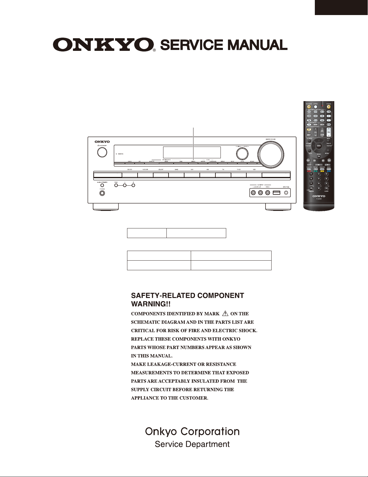
AV RECEIVER
MODEL HT-R592(B)
North American, Brazilian and Taiwanese models ---> “DIMMER”
Asian models ---> “RT/PTY/TP”
HT-R592
Ref. No. 4438
032013
Black model
120V AC, 60HzB MDF
Black model for HT-S5600
B MDC, B MDS
B MMK, B MMQ
120V AC, 60Hz
220-240V AC, 50/60Hz
RC-863M
Page 2
SERVICE PROCEDURE
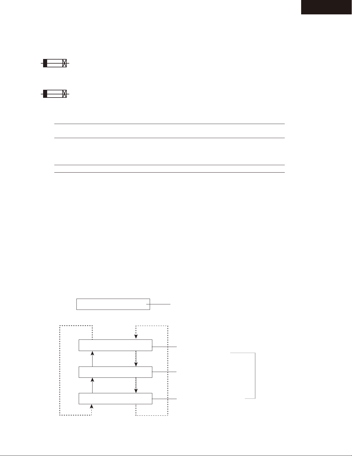
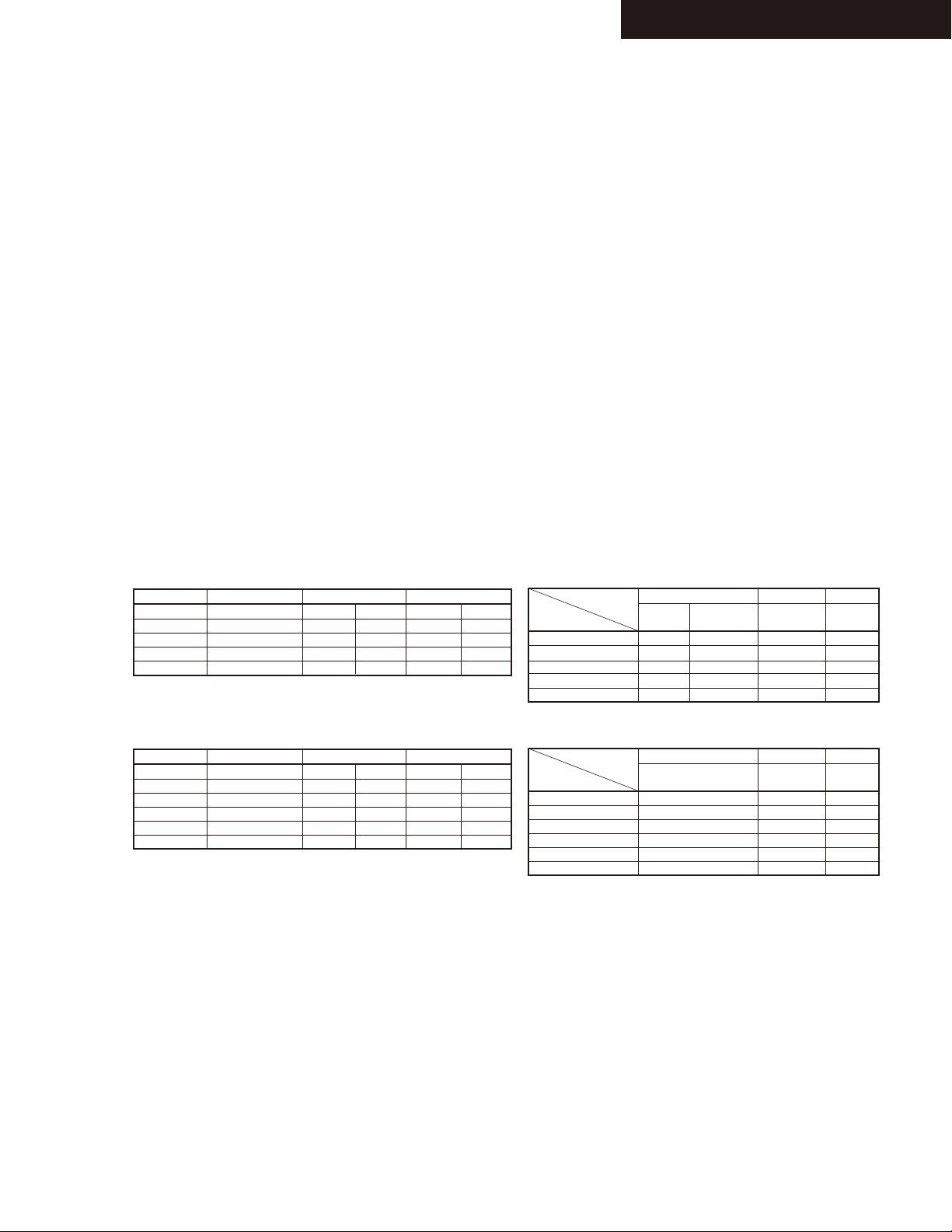
1. Replacing the fuses
This symbol located near the fuse indicates that the
fuse used is slow operating type, For continued protection against
fire hazard, replace with same type fuse, For fuse rating, refer to
the marking adjacent to the symbol.
Ce symbole indique que le fusible utilise est e lent.
Pour une protection permanente, n'utiliser que des fusibles de meme
type. Ce demier est indique la qu le present symbol est apposre.
REF NO. PART NAME DESCRIPTION PART NO. REMARKS
F6401, F6402
F6401, F6402 or
F901
F901 or
F901
F901 or
R9001
FUSE
FUSE
FUSE
FUSE
FUSE
FUSE
FUSE
10A-UL/T-233
10A-T/UL-ST2
8A-UL/T-233
8A-T/UL-ST2
4A-SE-EAK
4A-SE-TL250V
5A-UL-125V
252330GR
252333GR
252329GR
252261GR
252077GR
252277GR
252385T
[Notes]
<MDC> : 120V,Canadian model
<MDF> : 120V,Taiwanese model
<MDS> : 120V,Brazilian model
<MMK> : 220/230-240V, Korean model
<MMQ> : 220/230-240V,Hong kong model
!
!
!
<MDC, MDS, MDF>
!
<MDC, MDS, MDF>
!
<MMK, MMQ>
!
<MMK, MMQ>
!
HT-R592
2. Safety check out
(U.S.A. model only)
After correcting the original service problem, perform the following safety check before releasing the unit to the customer.
Leakage current Check
Measure the leakage current to a known earth ground (water pipe or conduct etc.) by connecting a leakage current
tester between the earth ground and exposed metal parts of the unit (input/output ground terminals,
screw heads or metal overlays etc.).
Plug the power supply cord directly into a 120Vac 60Hz wall socket and turn ON/STANDBY button on.
Any current measured must not exceed 0.5mA.
3. To initialize the unit
Press ON/STANDBY button while pressing down VCR/DVR button when the unit is POWER ON, then
the FL displays "CLEAR", and turn to STAND-BY.
Remove power cord from power line.
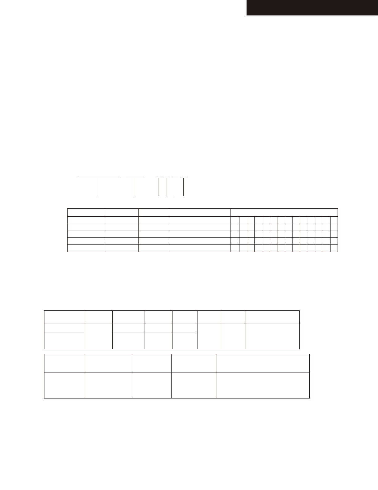
4. To check version of each Firmware
a. Push STANDBY/ON key while pushing down DISPLAY key to display MMPU(Main Microprocessor) version.
e.g.
M1.00/13302ALU
b. In display version, + (TONE) key and - (TONE) key are pushed to display another F/W version.
-
(TONE)
e.g.
-
(TONE)
e.g.
-
(TONE)
e.g.
M1.00/13302ALU
D1.00/13125aLA
O1.00/13119AL
+(TONE)
+(TONE)
+(TONE)
Version of MMPU displayed only for 3 seconds.
MMPU
(Main Microprocessor)
DSP
HDMI/Video Microprocessor
Version displayed
only for 3 seconds.
Page 3
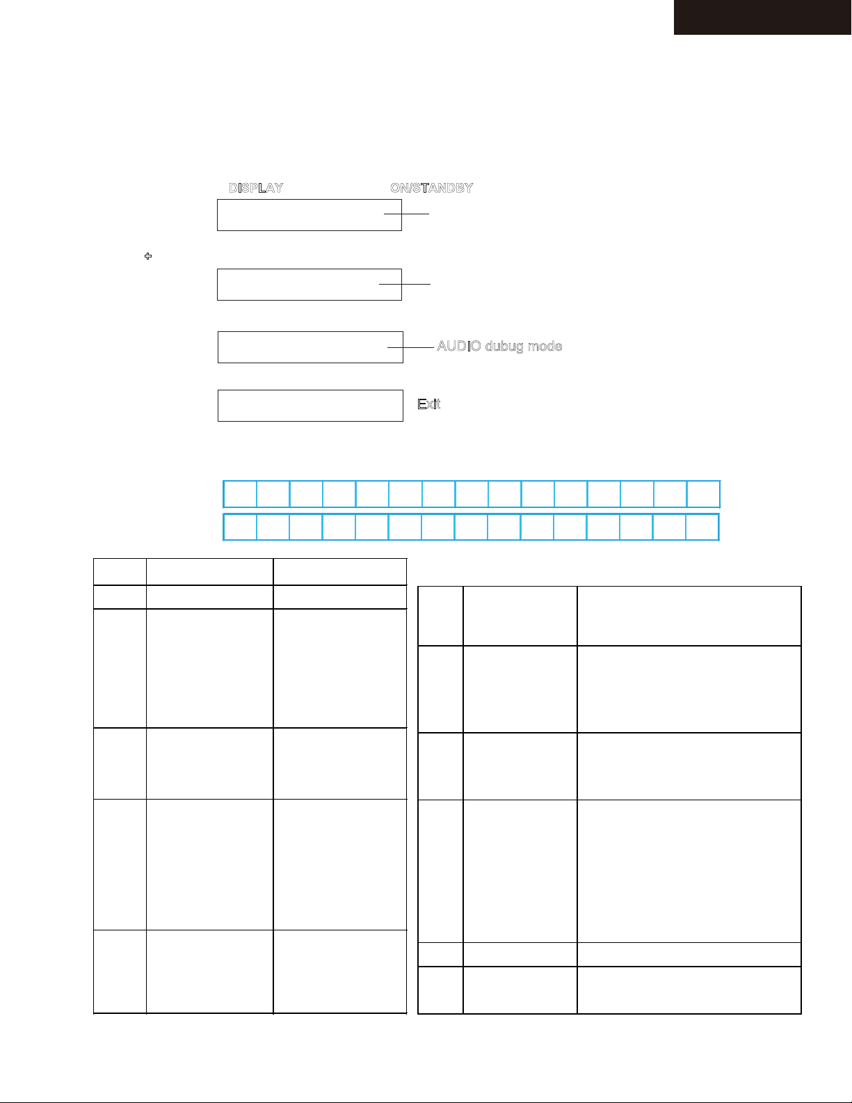
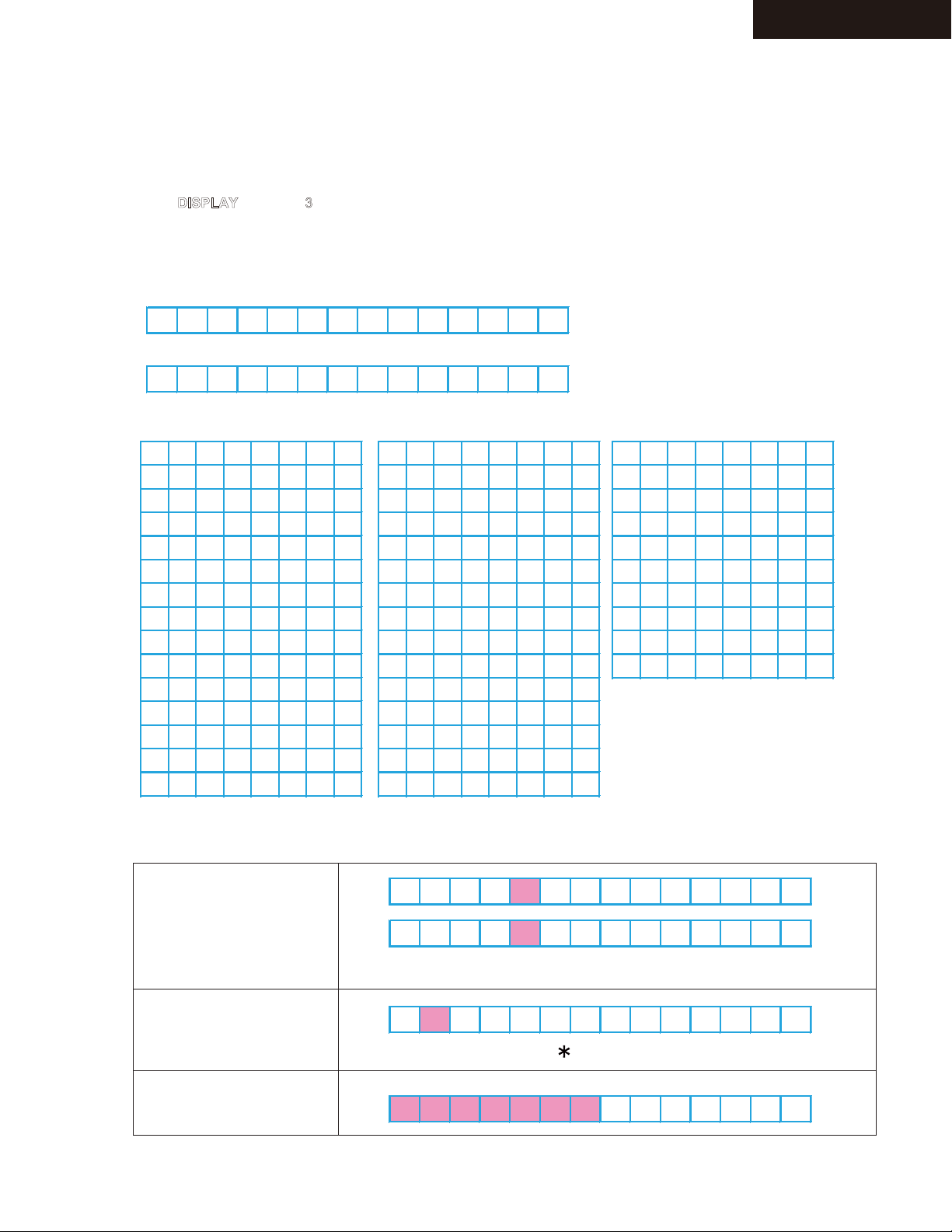
DEBUG MODE-1
4 D 4 8 K 1 N 0 F F P o 0
1 2 3 4 5 6 7 8 9 10 11 12 13 14 15
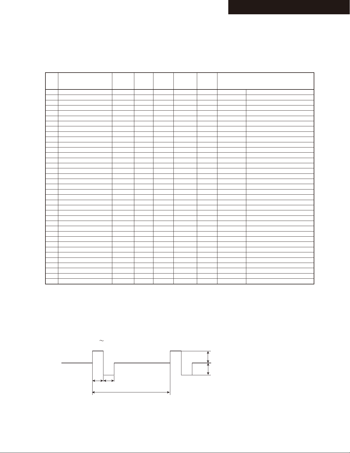
AUDIO DEBUG MODE-1/3
The operations of DSP and DIR etc are able to checked by the information displayed on FL in this debug mode.
This information will help to analysing digital audio no sound trouble.
To set in Debug mode
1. Press and hold down DISPLAY button, then press ON/STANDBY button.
2. Press + (TONE) button while the version number of microprocessor is displayed.
3. Press DISPLAY button while the version number of DSP is displayed.
4. Press DISPLAY button.
e.g.
e.g.
e.g.
e.g.
M1.00/13302ALU
D1.00/13125aLA
4D48K1N 0FFPo0
The version number of microprocessor is displayed
only for 3 seconds.
The version number of DSP is displayed
only for 3 seconds.
AUDIO dubug mode
Exit
HT-R592/ 2295
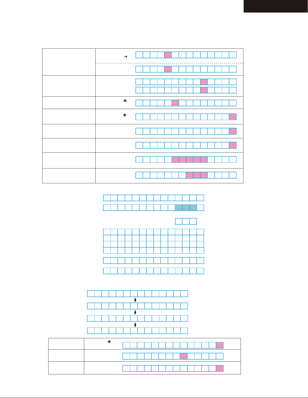
Contents of Display
Number of digits -->
Number of
digits
Contents State
1 DIR INPUT LOCK/UNLOCK E:UNLOCK
:LOCK
2 DIR INPUT RX
0:None
1:COAX1
2:COAX2
3:OPT1
4:OPT2
5:FRONT
8:HDMI1
9:HDMI2
3 DIR/ADC,FIX MODE D:Digital(SPDIF)
A:Analog
M:AnalogMultich
p:PCM FIXED
d:DTS FIXED
4-6 Sampling Freq,Emphasis 32K: 32 kHz w/o Emphasis
44K: 44.1kHz w/o Emphasis
48K: 48 kHz w/o Emphasis
64K: 64 kHz
88K: 88.2kHz
96K: 96 kHz
176:176.4kHz
192:192 kHz
32e: 32 kHz w Emphasis
44e: 44.1kHz w Emphasis
48e: 48 kHz w Emphasis
7 DIR DETECT TYPE 0:Analog
1:PCM
2:Not PCM
3:Data
4:DTS CD(Not used)
5:Multich
6:Not Decided
FL Display (e.g.)
8 CODEC CLOCK MODE N:Normal
U:Up Sampling
H:High Sampling(Double Rate)
D:Down Smapling
Q:Quad Rate
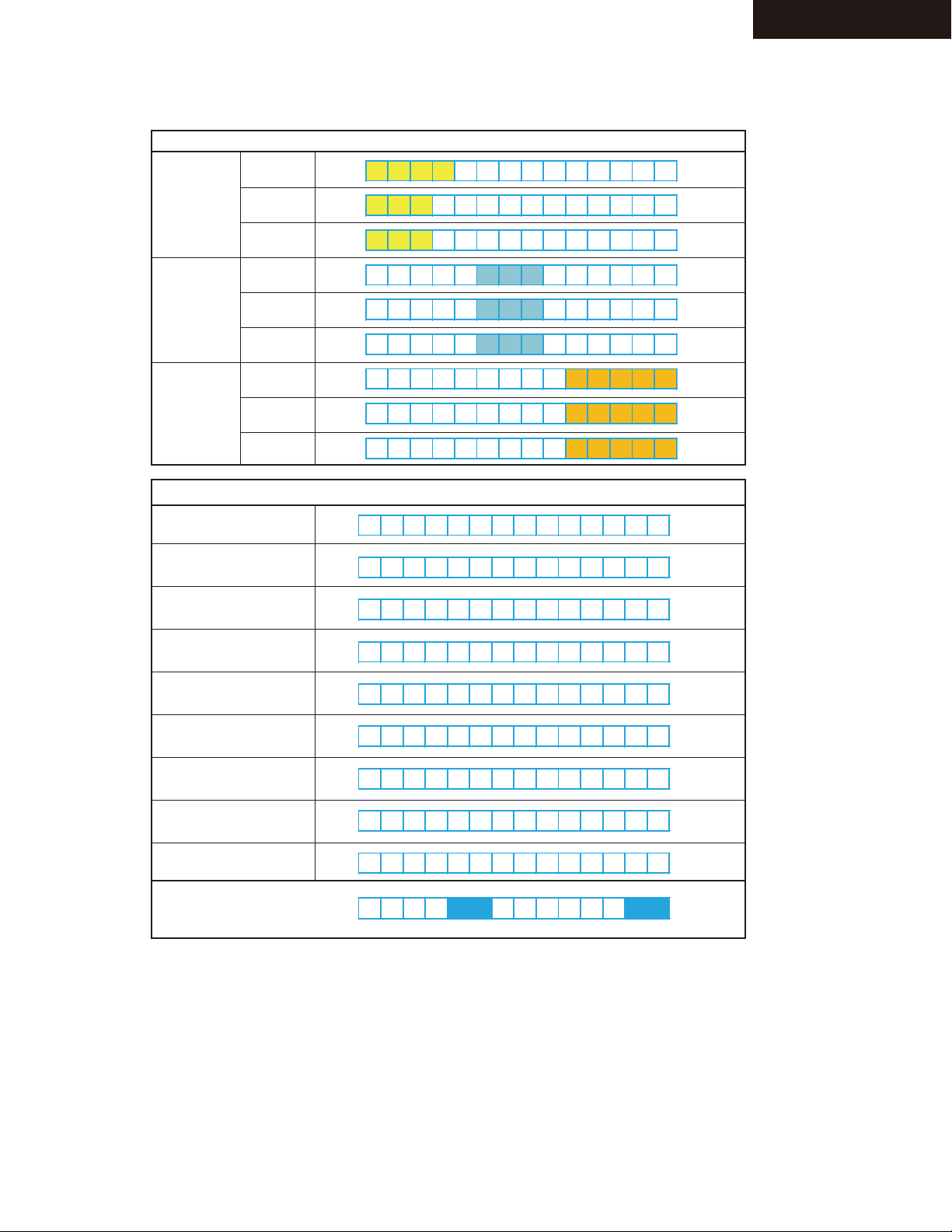
10 DSP PORT bit0:NIC
bit1:DEC
bit2:BUSY
bit3:EXEC WAIT
Refer to "NIC DEC SPI Busy Ecec wait"
in DEBUG MODE-2
11-12 DSP SEQUENCE 00-FE:NotFree
2D:Mute Control
FF:Free
Refer to "DSP Sequence" in
13 DSP DETECT FORMAT P:PCM(Analog)
D:Dolby Digital
d:DTS
A:AAC
d:DTS
A:AAC
S:DSD
p:DolbyDigital+
T:TrueHD
H:DTSHD High Resolution
M:DTSHD MaterAudio
?:UNKNOWN
14 DSP DECODE OK o:OK
x:NG
15 Mute 1:Selector
2:Effector
4:DSP
8:DIR
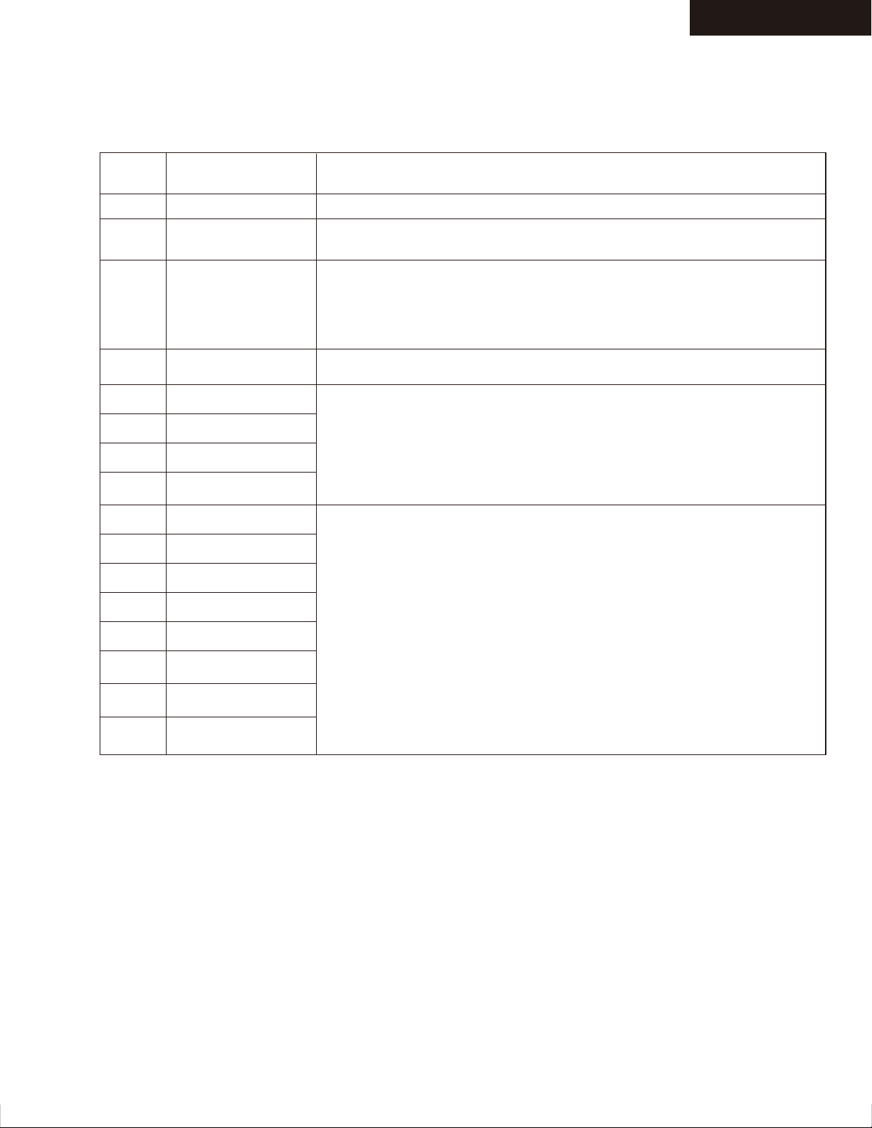
DEBUG MODE-3
Page 4
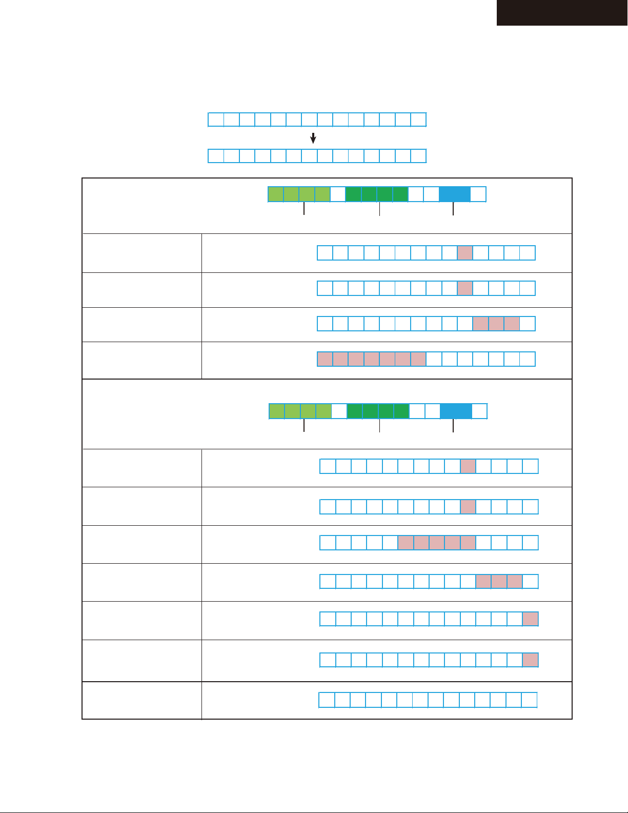
DEBUG MODE-2
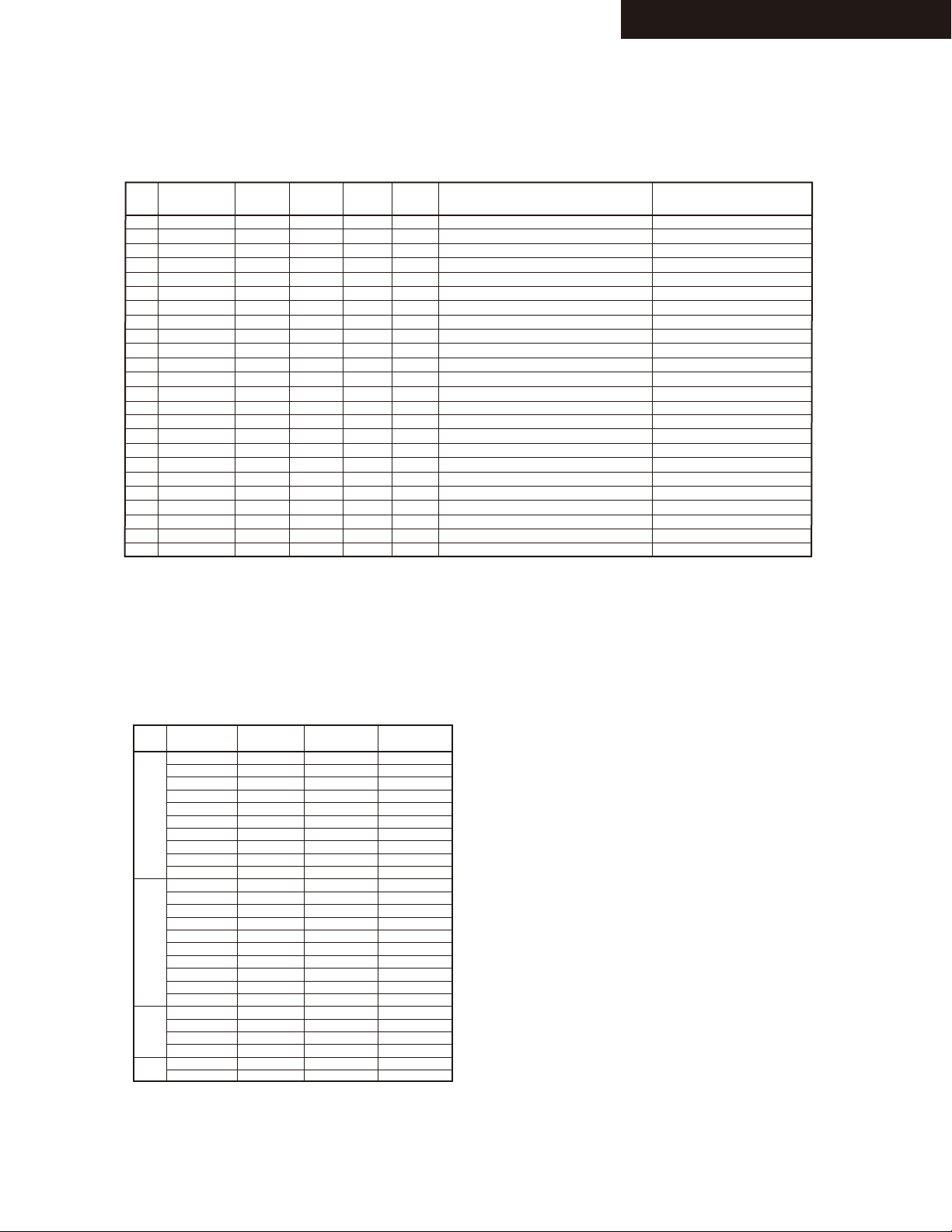
AUDIO DEBUG MODE-2/3
NIC/DEC/SPI Busy/Exec wait
HT-R592/ 2295
Display
contents
0
1
2
3
4
5
6
7
8
9
Internal state Inferred state
Stable state
NIC
DEC
NIC+DEC
SPI Busy
SPI Busy + NIC
SPI Busy + DEC
SPI Busy + NIC + DEC
Exec wait
Exec wait + NIC
If the stop remains "1" is indicated, it is possible that there is an abnormality in
the connection between the microcomputer and the NIC.
Please check if the input signal Dolby / DTS / AAC / PCM from Coax or OPT.
If the stop remains “2” is indicated, it is possible that there is an abnormality
in the connection between the DIR and the DSP.
There is a case of "2" for the state to stop or pause playback equipment.
And it is normal.
If the stop remains "3" is indicated, it is possible that there is an abnormality in
the connection between the microcomputer and the NIC.
If the stop in these numbers, it is possible that there is an abnormality in
the connection between the DSP and the microcomputer.
If you stop at these numbers, please check the DSP Sequence.
Exec wait + DEC
A
Exec wait + NIC+DEC
B
Exec wait + SPI Busy
C
Exec wait + SPI Busy
D
+ NIC
Exec wait + SPI Busy
E
+ DEC
Exec wait + SPI Busy
F
+ NIC + Dec
Page 5

DEBUG MODE-3
AUDIO DEBUG MODE-3/3
DSP Sequence
Display
contents
Stop at "03"
is indicated.
Inferred state
Have not been able to communicate
between the microcontroller and
the DSP.
HT-R592/ 2295
Possible Causes
1.There is a problem with the connection between the FlashROM and
the DSP, and the SDRAM.
2.Power is not supplied to the DSP.
3.Operation clock is not input to the DSP.
4.Reset port of the DSP is not connected.
5.There is a problem with the line of communication between the
microcontroller and DSP.
6.DSP is broken or Microcomputer.
7.Program has not been successfully written to the Flash ROM. Or the
program is not written.
8.Communication port (such as DIR) other devices are connected to t
he SPI mode is broken short. Terminals are short-circuited.
Stop at "05"
is indicated.
Stop at "08"
is indicated.
Stop at
"09 - 0C"
is indicated.
Stop at "17"
is indicated.
Stop at “21”, to return to the
previous display after a while.
Format display indicator flashes.
Stop at
"22-24"
is indicated.
Have not been able to write from
the boot loader of the DSP.
While running the boot loader of DSP,
the main program is not running.
Main program of DSP is not working
properly.
There is a possibility that the power is
turned off during the S / PDIF Update.
Main program of DSP is not working
properly.
main program of DSP is not working
properly.
The audio signal is not input.
1.Program is not written correctly to Flash ROM.
2.DSPSDO line of microcomputer is interrupted somewhere.
3.There is a problem with the FlashROM (or SDRAM) of DSP.
4.DSP is broken or Microcomputer.
5.Upper address bus of Flash ROM is not connected properly.
1.SDRAM is broken or Flash ROM.
2.Upper address bus of Flash ROM is not connected properly.
3.Program is not written correctly to Flash ROM.
4.There is a possibility that the power is turned off during
the S / PDIF Update.
1.SDRAM is broken or Flash ROM.
2.Upper address bus of Flash ROM is not connected properly.
3.Program is not written correctly to Flash ROM.
4.There is a possibility that the power is turned off during
the S / PDIF Update.
Solution :
Hold down the VCR/ DVR when the power is turned on, press the
On/Standby key. (Clear)
When out of the state of S / PDIF Update, please press the
On/Standby key.
1.SDRAM(or Flash ROM) is broken.
2.Upper address bus of Flash ROM is not connected properly.
3.Program is not written correctly to Flash ROM.
4.Operation clock to the DSP is not a predetermined value.
1.SDRAM(or Flash ROM) is broken.
2.Upper address bus of Flash ROM is not connected properly.
3.Program is not written correctly to Flash ROM.
4.Operation clock to the DSP is not a predetermined value.
5.Audio clock to the DSP is not a predetermined value.
Stop at
"30-33"
is indicated.
Stop at
"26-2F"
is indicated.
Stop at "FF"
is indicated.
main program of DSP is not working
properly.
The audio signal is not input.
DSP settings has failed.
The DSP is functioning properly.
There is no sound even though it is
the display of "FF".
1.SDRAM(or Flash ROM) is broken.
2.Upper address bus of Flash ROM is not connected properly.
3.Program is not written correctly to Flash ROM.
1.SDRAM(or Flash ROM) is broken.
2.Upper address bus of Flash ROM is not connected properly.
3.Program is not written correctly to Flash ROM.
All settings are completed, DSP has started normal operation.
Refer to
“NIC/DEC/SPI Busy/Exec wait” in DEBUG MODE-2
Page 6
DEBUG MODE-4
4 8 0 i / 6 0
4 8 0 p / 6 0
1 0 8 0 i / 6 0
7 2 0 p / 6 0
1 0 8 0 p / 6 0
2 4 0 p / 6 0
# 4 8 0 i / 6 0
# 4 8 0 p / 6 0
# 2 4 0 p / 6 0
5 7 6 i / 5 0
5 7 6 p / 5 0
1 0 8 0 i / 5 0
7 2 0 p / 5 0
1 0 8 0 p / 5 0
2 8 8 p / 5 0
# 5 7 6 i / 5 0
# 5 7 6 p / 5 0
# 2 8 8 p / 5 0
1 0 8 0 p / 2 4
1 0 8 0 p / 2 5
1 0 8 0 p / 3 0
V G A
1 0 8 0 i 1 0 0
7 2 0 p 1 0 0
5 7 6 p 1 0 0
5 7 6 i 1 0 0
1 0 8 0 i 1 2 0
7 2 0 p 1 2 0
4 8 0 p 1 2 0
4 8 0 i 1 2 0
5 7 6 p 2 0 0
5 7 6 i 2 0 0
4 8 0 p / 6 0
4 8 0 p 2 4 0
4 8 0 i 2 4 0
* 4 8 0 p / 6 0
* 5 7 6 p / 5 0
7 2 0 p / 2 4
7 2 0 p / 2 5
7 2 0 p / 3 0
1 0 8 0 i / 6 0
→
1 0 8 0 i / 6 0
4 8 0 I / 6 0
→
4 8 0 P / 6 0 →
* V G A →
U n k n o w n →
HDMI DEBUG MODE-1/4
HDMI-related operations can be checked to some extent by displaying HDMI debug mode.
To enter this mode
Hold down DISPLAY button for 3 seconds. Information display will last for about 8 seconds.
Resolution display method
Input resolution
Output resolution
List of standard resolution
HT-R592/ 2295
Display of Input Resolution
DVI input signal
VGA input signal
No input
“I” and “P” will be capitalized.
Display the ” ” in column 1
Page 7
DEBUG MODE-5
→ 1 0 8 0 i / 6 0
1 0 8 0 i / 6 0
4 8 0 I / 6 0
4 8 0 P / 6 0
* 4 8 0
p
/ 6 0
4 8 0 p / 6 0 *
4 8 0 p / 6 0
#
4 8 0 p / 6 0
x
- - - - -
O F F
1 0 8 0 i / 6 0 →
* * * * x * * * * p / * *
* * *
3 8 4 0 x 2 1 6 0 p / 3 0
3 8 4 0 x 2 1 6 0 p / 2 5
3 8 4 0 x 2 1 6 0 p / 2 4
4 0 9 6 x 2 1 6 0 p / 2 4
3 8 4 0 x 2 1 6 0 p / 3 0 x
3 8 4 0 x 2 1 6 0 p / 3 0 #
1 0 8 0
p
/ 2 4
(
3 D
)
H D M I 4 4 4 3 6 b i t
F r a m e P a c k i n g
I N
:
O U T
:
1 0 8 0
p
/ 2 4 ( 3 D ) *
H D M I 4 4 4 # 3 6 b i t
1 0 8 0
p
/ 2 4
(
3 D
)
x
HDMI DEBUG MODE-2/4
Dislay of Output Resolution
For a video processor
Via VSP
Display the ” ”
in column 4
VSP skip
HT-R592/ 2295
DVI input signal
VGA input signal
RSEN is OFF
EDID_READ is NG
Resolution Error
No output
(Signal output destination
can not be found.)
Hot-plug of Sink equipment
can not be detected.
4K Upscaling
Display of Input resolution
Display of Output resolution
List of resolution
i / p will be
capitalized.
Display the ” ”
in column 5
Display the ” ”
in column 14
Display the ” # ”
in column 14
Display the ” x ”
in column 14
→
If the three-digit numbers
are refrate
Resolution Error
EDID_READ_NG
3D Display
Resolution display
Status Display
3D format
INPUT/OUTPUT
RSEN OFF
EDID READ NG
Resolution Error
Display the ” ”
in column 14
Display the ” # ”
in column 9
Display the ” x ”
in column 13
Page 8
DEBUG MODE-6
H D M I 4 4 4 3 6 b i t
D V I 4 4 4 3 6 b i t
- - - 4 4 4 3 6 b i t
H D M I R G B 3 6 b i t
H D M I 4 2 2 3 6 b i t
H D M I 4 4 4 3 6 b i t
H D M I R G B 2 6 b i t
H D M I R G B 3 0 b i t
H D M I R G B 3 6 b i t
F r a m e P a c k i n g
F a l t e r n a t i v e
L a l t e r n a t i v e
S i d e b y S i d e ( F )
L + d e p t h
L + d e p t h g r a p h i c
S i d e b y S i d e ( H )
T o p - a n d - B o t t o m
U N K N O W N
I N
: * *
O U T
: * *
HDMI DEBUG MODE-3/4
Status
Input Mode
Input Color
Deep Color
HDMI input
DVI input
No input
RGB
422
444
24bit
30bit
36bit
HT-R592/ 2295
3D format
Frame Packing
Field alternative
Line alternative
Side-by-Side(Full)
L+depth
L+depth + graphics
Side by Side(Harf)
Top and Bottom
unknown
INPUT/ OUTPUT
Page 9
DEBUG MODE-7
1 0 2 4 x 7 6 8 p / 6 0 →
1 0 2 4 x 7 6 8 p / 6 0
* * * * x * * * * p / * *
→
1 0 2 4 x 7 6 8 P / 6 0
→
1 0 2 4 x 7 6 8 p / 6 0
→
1 0 2 4 x 7 6 8 P 1 2 0
→
U N K N O W N
* * * * x * * * *
p
/ * *
1 0 2 4 x 7 6 8 P / 6 0
1 0 2 4 x 7 6 8 p / 6 0
→
- - - - -
1 0 2 4 x 7 6 8 P 1 2 0
1 0 2 4 x 7 6 8 P / 6 0 #
1 0 2 4 x 7 6 8 P / 6 0
x
I N
:
* O U T
:
*
HDMI DEBUG MODE-4/4
PC Resolution
Input Resolution
Output Resolution
Display of Input resolution
HT-R592/ 2295
DVI input
HDMI input
Three-digit numbers
are Referat
No input
Display uppercase P/I
Display lowercase p/i
Display of Output resolution
DVI output
HDMI output
Display uppercase P/I
Display lowercase p/i
Horizontal resolution
Horizontal resolution
Vertical resolution
Vertical resolution
Referat
Referat
Display”-----”
Three-digit numbers
are Referat
EDID READ NG
Resolution through
INPUT/ OUTPUT
Display the ” # ” in
column 13
Display the ” x ” in
column 13
Page 10

HT-R592/ 2295
DEBUG MODE-8
SERVICE INFORMATION MODE
Displaying Service information
This service information display system is helpful in analyze the status when the unit goes into Protect mode and is powered off.
Pay attention that the status will change if a button is pushed.
1. Press twice the ON/ STANDBY key while pressing the DISPLAY key.
e.g.
M 1 . 0 0 / 1 3 3 0 2 A L U
2. Press SETUP button within 3 seconds above.
e.g.
- 8 0 F 2 7 D D
The version of main microprocessor is
displayed only for 3 seconds.
Information Displayed (Record this Information)
Power off Cause
T : Thermal Protect
Temperature
: xx F or xx C
Volume Level Listenning Mode
---> Refer to the code list below.
V : Voltage Protect
I : Current Protect
- : Other
Listening Mode Code List
C_LM_LAST01
C_LM_PURE02
C_LM_DIRECT03
C_LM_STEREO04
C_LM_MONO05
C_LM_SURR20
C_LM_THX_MUSIC50
C_LM_THX_GAME70
C_LM_THX_CINEMA90
C_LM_THX_U2GAMEA0
C_LM_THX_U2MUSICA8
C_LM_THX_U2CINEMAB0
C_LM_AUDYSSEYD0
C_LM_DTSSS48
C_LM_ORCHESTRA06
C_LM_UNPLUGGED07
C_LM_STUDIOMIX08
C_LM_TVLOGIC09
C_LM_ALLCHST0A
C_LM_FULLMONO0B
C_LM_TD0C
C_LM_TESTTONEF1
C_LM_TESTTHRF2
C_LM_TESTAUTOF3
3. Press SETUP button again. The following information are displayed.
e.g.
Time after Power on
xx : xx
0 1 : 2 3 1 0 h
Time after Initialize
xx hour
Information Displayed (Record this Information)
C_LM_ASCF4
C_LM_FLASHF5
C_LM_DEBUGMODEF6
C_LM_FLASH2F7
C_LM_FLASH3F8
C_LM_FLASH4F9
C_LM_FLASH_CHECKFA
C_LM_RPG0D
C_LM_ACTION0E
C_LM_ROCKBAND0F
C_LM_SPORTS10
4. Press ON/STANDBY button to exit the display of service information.
(Ref.: Press RETURN button to initialize the data in the service information.)
P r o t e c t D a t a C L R
Normal display
Page 11

TX-NR525/HT-R592/HT-RC550
OPERATION CHECK-1
1.OPERATION CHECK(1/2)
1-1. OPERATIONS OF VOLTAGE-DETECTION PROTECTORS.
See “OPERATION CHECK-3,-5” for TEST MODE operation.
NOTE: Don't connect load nor short speaker terminals.
a. Change the state to "TEST-4-21".
b. It tests by being automatic in order of TEST 4-21(FL+) → 22(FR-) → 23(C+) → 24(SL-) → 25(SR+) → ( 26(SBL-)
→ 27(SBR+) ). If TEST 4-27(TX-NR525/HT-RC550 are 4-25) is OK, it becomes the display of "TEST-4-35".
c. It will complete, if displayed on FL TUBE as "TEST 4-35".
1-2. OPERATIONS OF CURRENT-DETECTION PROTECTORS
See “OPERATION CHECK-3,-5” for TEST MODE operation.
a. Change the state to "TEST-4-35".
Even if you connect 3-ohm load for every channel of L, R, C, SL, SR, SBL and SBRch, a relay should not cut off.
If 1-ohm load is connected for every channel of L, R, C, SL, SR,SBL and SBRch, a relay should hold the state of ON.
1-3. CONFIRMATION OF RDS (RADIO DATA SYSTEM) OPERATION (Applied to MM*/MP* type )
a. Input 98MHz,30dBμ signal modurated with RDS data.
b. When a PS information is received, the name of the station "RDS TEST" shall be displayed within 2 seconds instead
of the frequency.
1-4. CONFIRMATION OF HEAD PHONE OPERATION.
Confirm the Listening Mode is automatically switched to "STEREO" mode when headphones plug is inserted into
the PHONES jack.
1-5. COMFIRMATION OF FRONT USB
See “OPERATION CHECK-3,-4” for TEST MODE operation.
a. Connect ipod to AVR USB port.
b. When set to TEST 3-09, confirm that the display of AVR change "connecting" to "Push [MODE] b ..." or "Playlist" after
few seconds.
The following iPod models can be used for inspection.(The above-mentioned operation is not done excluding the
following items.)
iPod classic, 3G nano, 4G nano, 5G nano
1-6. COMFIRMATION OF REAR USB(Applied to TX-NR525/HT-RC550)
See “OPERATION CHECK-3,-4” for TEST MODE operation.
a. Connect USB-Storage to AVR USB port.
b. When set to TEST 3-10, confirm that the display of AVR change device name.
1-7. COMFIRMATION OF NETWORK(Only TX-NR525/HT-RC550)
See “OPERATION CHECK-3,-4” for TEST MODE operation.
a. Connect the receiver to the router.
b. When set to TEST3-18 confirm that the display of AVR change IP adress.
*Please wait for about 1 minute after turning on the power supply of the set when you use TEST 3-18.
1-8. CONFIRMATION OF OUTPUT SENSER AND THERMAL SENSOR
See “OPERATION CHECK-3,-5” for TEST MODE operation.
a. Set the TEST MODE to "TEST 4-36" and "TEST 4-37".
After light "FM STEREO" on FL display ,
the relays RL641/642 is OFF and "FM STEREO"is off .(TEST 4-37 is only for HT-R592)
b. Push ON/Standby button 2 times while pushing down DISPLAY button to display CPU Debug PROGRAM version.
Push TONE button while displaying CPU PROGRAM version to display value of temparature sensor.
Confirm outside temperature ±20C is displayed immediately after energizing.
Note that the error margin is caused by the rise of the temperature of the heat sink when time passes.
FL Display
e.g.
000 034 F:x S:H
Voltage
of VOLH port
Temparature
of thermal sensor
FAN condition
x: Stop
L: Low speed
M: Mid speed
H: High speed
Amplifier power
supply voltage condition
H: High-B
L: Low-B
Page 12
TX-NR525/HT-R592/HT-RC550
OPERATION CHECK-2
1.OPERATION CHECK(2/2)
1-9. CONFIRMATION OF OSD(ON SCREEN DISPLAY) OPERATION
a. When SETUP(HT-R592) or HOME(TX-NR525/HT-RC550) button is pushed, confirm that setup menu
is displayed in HDMI Out.
b. Confirm that specified operations for ENTER(with 4-cursor) buttons are made.
1-10. CONFIRMATION OF HDMI AUDIO OPERATION.
See “OPERATION CHECK-3,-6” for TEST MODE operation.
a. CO
DTS-HD MasterAudio 7.1ch
Dolby TrueHD 7.1ch
2. Change the state to TEST 6-00. Confirm the signal is output from L/R,SW/C,SL/SR,SBL/SBR.
3. When TEST 6-08, confirm the sound(HDMI1 input) outputs from the TV.
b. CONFIRMATION OF HDMI SPDIF SIGNAL
5. When TEST 6-06, confirm the sound(HDMI IN1) outputs from the speaker.
6. When TEST 6-07, confirm the sound(BD/DVD analog input) outputs from the TV.(VIDEO is Blue back.)
7. When TEST 6-10,11,12, confirm the sound of DSD 5.1ch input HDMI IN 3, output from the speaker.
NFIRMATION OF HDMI I2S SIGNAL
1. Input the one of these signals below from HDMI1 terminal.
4. SPDIF signal is input from HDMI terminal.
c. CONFIRMATION OF HDMI DSD SIGNAL.
1-11. VIDEO FUNCTION CHECK
See “OPERATION CHECK-3,-6” for TEST MODE operation.
a. Confirm Video output signal as shown Table 2, while Video signal are input as shown Table 1.
NOTE 1: Confirm the HDMI path at 1080p signal.
Applied to HT-R592
Table 1
Input
BD/DVD
VCR/DVR
CBL/SAT
GAME
AUX
Composite Video
A
B
C
D
E
Component
IN1
--IN2
---
---
HDMI
F
IN1
---
IN2
G
IN3
---
IN4
---
---
H
I
J
K
---
Applied to TX-NR525/HT-RC550.
Table 1
Input
BD/DVD
IN2
CBL/SAT
GAME
PC
AUX
Composite Video
A
--B
C
D
E
Component
IN1
--IN2
---
---
---
HDMI
F
IN1
---
IN2
G
IN3
---
IN4
---
IN5
---
IN6
H
I
J
K
L
M
b. OPERATIONS OF VIDEO SIGNAL-DETECTION
1. Confirm "RDS" light up on FL TUBE when component video signal is input in "TEST 5-00".
Confirm "RDS" turn off on FL TUBE when component video signal isn't input in "TEST 5-00",too.
2. Confirm "FM STEREO" light up on FL TUBE when component video signal is input in "TEST 5-00".
Confirm "FM STEREO" turn off on FL TUBE when component video signal isn't input in "TEST 5-00",too.
Table 2
Test mode
5-05(BD/DVD)
5-06(VCR/DVR)
5-07(CBL/SAT)
5-08(GAME)
5-10(AUX)
Table 2
Test mode
5-05(BD/DVD)
5-06(IN2)
5-07(CBL/SAT)
5-08(GAME)
5-09(PC)
5-10(AUX)
Composite Video
VCR out
A
--C
D
E
Monitor out
A
B
C
D
E
Composite Video
Monitor out
A
B
C
D
E
Component
OUT
F
--G
---
---
Component
OUT
F
--G
---
---
---
HDMI
OUR
H
I
J
K
---
HDMI
OUR
H
I
J
K
L
M
1-12. MISCELLANEOUS
a. Confirm all input and output terminals operate normally.
b. Please confirm LED and FL displaying by the FL TEST mode. And confirm the destination setting.
---> See to “OPERATION CHECK-3”.
c. Change the state to KEY TEST under TEST MODE to confirm each key operation.
---> See to“OPERATION CHECK-3”.
d. Confirm the version of each firmware.
---> See to “SERVICE PROCEDURE-2”.
e. Confirm the firmware combination check.
---> See to “OPERATION CHECK-3”.
Page 13
TX-NR525/HT-R592/HT-RC550
OPERATION CHECK-3
2.TEST MODE(1/4)
2-1.TEST MODE FOR MODEL, DESTINATION AND FL DISPLAY
[NOTE] If VOL value is not 25(initial setting), test mode cannot be set.
a. Push STANDBY/ON key while pushing down TV/CD button button to display "TEST-".
b. Then push DIMMER(RT/PTY/TP) button and get the FL test mode.
c. In the FL test mode, TONE + button is FL TEST UP and TONE - button is FL TEST DOWN.
d. REC OUT and ZONE2 button's originally operation can't work when it is in FL test mode.
e. The contents of the step are as follows.
1. Lit all segment
2. Lit '23456789ABCDEF'
3. Lit a even number segment
4. Lit an odd number segment
5. The Destination setting is displayed. Please see the below for detail.
f. To close the FL test, push POWER button.
Display of Destination on TEST MODE.(Distination setting)
e.g.
N R 5 2 5 D x 2 0 0 0
FL DIS Name Destination A B
C
D
A:Value of AD port of BAND
B:Value of AD port of INIT1
C:Value of AD port of INIT2
D:Value of AD port of INIT3
Model Name Distination Number Writing Data
TX-NR525 Dx 2000 2000 TX-NR525 Dx N R 5 2 5 D x 2 0 0 0
TX-NR525 xx 8000 8000 TX-NR525 xx N R 5 2 5 x x 8 0 0 0
HT-RC550 Dx 2002 2002 HT-RC550 Dx R C 5 5 0 D x 2 0 0 2
HT-R592 Dx 2028 2028 HT-R592 Dx H T 5 9 2 D x 2 0 2 8
HT-R592 xx 8028 8028 HT-R592 xx H T 5 9 2 x x 8 0 2 8
FL Display
2-2. TEST MODE FOR OPERATION
a. Push STANDBY/ON button while pushing down TV/CD button to display "TEST-_".
b. Next, if the following keys are pushed, it becomes a each TEST MODE.
c. In the test mode, (TONE)- button is TEST MODE DOWN and (TONE)+ button is TEST MODE UP.
d. "TEST-1-00" and "TEST-1-01" are used to check a protection circuit, and the relay recovered in one second.
TEST MODE
HT-R592
TX-NR525
HT-RC550
TEST MODE
HT-R592
TX-NR525
HT-RC550
1-00 2-00 3-00 4-00 5-00 6-00 KEY TEST
CBL/SATVCR/DVR GAME
BD/DVD
IDLING TIMER FL TEST
TUNING MODE
(LATE NIGHT)
CBL/SAT GAME PC
DIMMER
(RT/PTY/TP)
AUX
FIRMWARE
COMBINATION
CHECK
ENTER
TV/CD
CHECK SUM
When MMPU debug version(*1)
is displayed, push
"MEMORY(CINEMA FILTER)"
MEMORY
(CINEMA FILTER)
(*1) MMPU debug version is displayed
Press twice the ON/ STANDBY key while pressing the DISPLAY key.
Page 14

OPERATION CHECK-4
2.TEST MODE(2/4)
2-2. TEST MODE FOR OPERATION(Continue)
e. Test mode is as follows.
TEST
Analog Input
No
[Rec Sel]
(Zone2/Zone3)
1-00
BD/DVD (Off)
1-01
BD/DVD (Off)
1-02
BD/DVD (Off)
2-00
BD/DVD (Off)
2-01
BD/DVD (Off)
2-02
BD/DVD (Off)
2-03
Multi channel
2-05
BD/DVD (Off)
2-06
BD/DVD (Off)
2-07
BD/DVD (Off)
2-08
BD/DVD (Off)
2-09
BD/DVD (Off)
2-10
BD/DVD (Off)
2-11
"VCR/DVR (Off) H59
2-12
"VCR/DVR(Off) H59
CBL/SAT (Off) T5/H55"
2-13
"CBL/SAT (Off) H59
GAME(Off) T5/H55"
2-14
"GAME (Off) H59
PC(Off) T5/H55"
2-15
AUX (Off)
2-16
BD/DVD (Off)
2-17
BD/DVD (Off)
2-18
TV/CD (Off)
2-19
BD/DVD (Off)
2-20
BD/DVD (Off)
2-21
BD/DVD (Off)
2-22
BD/DVD(Source)
2-23
MIC
2-24
MIC
2-25
AUX(Off)
2-26
PC (Off)
3-00
FM/Source
3-01
TV/CD
3-02
TV/CD
3-03
TV/CD
3-04
TV/CD (Off)
3-05
TV/CD
3-09
USB/(Source)
3-10
USB/(Source)
3-11
USB/(Source)
3-12
USB/(Source)
3-13
USB/(Source)
3-14
USB/(Source)
3-15
USB/(Source)
3-16
USB/(Source)
3-17
USB/(Source)
3-18
NET/(Source)
Listening Mode/
Input Format
Direct
Direct
Direct
Stereo(Direct)
Stereo(Direct)
DVD Direct
Multich Amp Test
ADC DSP 8ch Thru.
ADC DSP 8ch Thru.
ADC DSP 7ch Thru.
ADC DSP 8ch Thru.
ADC DSP 8ch Thru.
ADC DSP 8ch Thru.
Automatic
Automatic
DIR DSP 8ch Thru
DIR DSP 8ch Thru
DIR DSP 8ch Thru
DIR DSP 8ch Thru
DIR DSP 8ch Thru
Automatic
DIR DSP 8ch Thru
DIR DSP 8ch Thru
DIR DSP 8ch Thru
DIR DSP 8ch Thru
ADC DSP 8ch Thru.
ADC DSP 8ch Thru.
DIR DSP 8ch Thru
DIR DSP 8ch Thru
Stereo(Direct)
Stereo(Direct)
Stereo(Direct)
Stereo(Direct)
ALL CH STEREO
Stereo(Direct)
Stereo(Direct)
Stereo(Direct)
Stereo(Direct)
Stereo(Direct)
Stereo(Direct)
Stereo(Direct)
Stereo(Direct)
Stereo(Direct)
Stereo(Direct)
Stereo(Direct)
VIDEO
Input
BD/DVD
BD/DVD
BD/DVD
BD/DVD
BD/DVD
BD/DVD
BD/DVD
BD/DVD
BD/DVD
BD/DVD
BD/DVD
BD/DVD
BD/DVD
VCR/DVR
VCR/DVR
CBL/SAT
CBL/SAT
GAME
GAME
PC
AUX
BD/DVD
BD/DVD
BD/DVD
BD/DVD
BD/DVD
BD/DVD
BD/DVD
BD/DVD
BD/DVD
AUX
PC
BD/DVD
BD/DVD
BD/DVD
BD/DVD
BD/DVD
BD/DVD
Last
Last
Last
Last
Last
Last
Last
Last
Last
Last
Compo-
nent V
IN1
IN1
IN1
IN1
IN1
IN1
IN1
IN1
IN1
IN1
IN1
IN1
-
-
-
-
-
-
-
BD/DVD
BD/DVD
BD/DVD
BD/DVD
BD/DVD
BD/DVD
BD/DVD
-
-
BD/DVD
BD/DVD
BD/DVD
BD/DVD
BD/DVD
BD/DVD
-
-
-
-
-
-
-
-
-
-
HDMI
IN1
IN1
IN1
IN1
IN1
IN1
IN1
IN1
IN1
IN1
IN1
IN1
IN1
IN2
IN2
IN3
IN4
-
-
-
IN2
IN2
IN2
IN3
IN3
IN1
IN1
-
-
IN1
IN1
IN1
IN1
IN1
IN1
-
-
-
-
-
-
-
-
-
-
Digital Input
/Output
-
-
-
-
-
-
-
-
-
-
-
-
-
*OPT1
*COAX1
*OPT1
OPT1
COAX1
COAX1
*OPT2
*OPT2
*OPT2
*COAX2
*COAX2
-
-
OPT1
OPT1
-
-
-
-
-
-
Front USB
Rear USB
Front USB
Front USB
Front USB
Front USB
Front USB
Front USB
Front USB
NET
Config.
-
-
-
-
-
Y/L/L/L/L
Y/L/L/L/L
Y/L/L/L/L
Y/L/L/L/L
Y/L/L/L/L
Y/L/L/L/L
Y/L/L/L/L
Y/L/L/L/L
Y/L/L/L/L
Y/L/L/L/L
Y/L/L/L/L
Y/L/L/L/L
Y/L/L/L/L
Y/L/L/L/L
Y/L/L/L/L
Y/L/L/L/L
Y/L/L/L/L
Y/L/L/L/L
Y/L/L/L/L
Y/L/L/L/L
Y/L/L/L/L
Y/L/L/L/L
-
-
-
-
Y/L/L/L/L
-
-
-
-
-
-
-
-
-
-
-
Master Vol.
NonTHX
(THX)
Max
Max
MIN
Max
64
Max
64
62
64
57
45
MIN
64
64
64
64
64
64
Max
64
52
64
64
64
64
64
64
59
64
64
Max
64
64
64
MIN
57
57
48
48
48
48
48
48
48
48
TX-NR525/HT-R592/HT-RC550
Speaker
Relay
F/CS/SB/Z2
F/CS/SB/Z2
F/CS/SB/Z2
F
F
F/CS/SB
F/CS/SB
F/CS/SB
F/CS/SB
F/CS/SB
F/CS/SB
F/CS/SB
CS/SB
F/CS/SB
F/CS/SB
F/CS/SB
F/CS/SB
F/CS/SB
F/CS/SB
F/CS/SB
F/CS/SB
F
F
CS
F/CS/SB
F/CS/SB
F/CS/SB
F/CS/SB
F
F/Z2
F/Z2
F/Z2
F/CS/FH
F/Z2
F
F
F
F
F
F
F
F
F
F
etc.
SBL,SBR
SW=NO
SW=NO
SW:MUTE
SPRLF OFF
MICMUTE ON
Z2MUTE ON
"Output Level / Distortion"
Hum noise
Freq. Resp.
Freq. Resp.
Separation
Separation
"Output Level / Distortion"
"NET connectioncheck "
*1 PROTECT
"*1 PROTECTFOR SBL ch"
TX-NR525,HT-R550 only
1.44.1kHz_16bit_1kHz_
0dBfs_L&R.wav *2
2.44.1kHz_16bit_-∞
dBfs_L&R.wav *2
3.44.1kHz_16bit_20Hz_
0dBfs_L&R.wav *2
4.44.1kHz_16bit_20kHz_
0dBfs_L&R.wav *2
5.44.1kHz_16bit_1kHz_
0dBfs_Lch.wav *2
6.44.1kHz_16bit_1kHz_
0dBfs_Rch.wav *2
7.48kHz_16bit_1kHz_
0dBfs_L&R.wav *2
display IP address
Page 15
TX-NR525/HT-R592/HT-RC550
OPERATION CHECK-5
2.TEST MODE(3/4)
2-2. TEST MODE FOR OPERATION(Continue)
Auto Measurement Mode
[Note] Do not connect the loudspeaker.
TEST
DSP Output ch
No.
4-00
ALL
4-01
ALL
4-02
ALL
4-03
SW
4-04
FL,FR
4-05
FR,C,SL,SR,SBL,SBR,SW
4-06
FL,C,SL,SR,SBL,SBR,SW
4-07
FL,FR,SL,SR,SBL,SBR,SW
4-08
FL,FR,C,SR,SBL,SBR,SW
4-09
FL,FR,C,SL,SBL,SBR,SW
4-10
FL,FR,C,SL,SR,SBR,SW
4-11
FL,FR,C,SL,SR,SBL,SW
4-12
FL,FR,C,SL,SR,SBL,SBR
4-13
ALL
4-14
ALL
4-15
ALL
4-16
ALL
4-21
FL
4-22
FR
4-23
C
4-24
SL
4-25
SR
4-26
SBL
4-27
SBR
4-28
FL
4-29
FR
4-30
C
4-31
SL
4-32
SR
4-33
SBL
4-34
SBR
4-35
ALL
4-36
"FL,FR,C,SL,SR"
4-37
C,SL,SR,SBL,SBR
4-38
ALL
4-39
ALL
4-40
ALL
DSP Output
Frequency
1kHz
30Hz
20kHz
30Hz
30Hz
10kHz
10kHz
10kHz
10kHz
10kHz
10kHz
10kHz
30Hz
1kHz
30Hz
1kHz
30Hz
+DC
-DC
+DC
-DC
+DC
-DC
+DC
-DC
+DC
-DC
+DC
-DC
+DC
-DC
Pulse
1kHz
1kHz
1kHz
30Hz
20kHz
DSP
Output
Voltage
-20dBFS
-20dBFS
-20dBFS
-20dBFS
-20dBFS
-20dBFS
-20dBFS
-20dBFS
-20dBFS
-20dBFS
-20dBFS
-20dBFS
-20dBFS
-20dBFS
-20dBFS
-20dBFS
-20dBFS
+Max
-Max
+Max
-Max
+Max
-Max
+Max
-Max
+Max
-Max
+Max
-Max
+Max
-Max
Max
0dBFS
0dBFS
-20dBFS
-20dBFS
-20dBFS
In all test modes, it is not concerned with detection of VOLH but SEC1H are made "H" fixation. (Except TEST4-36 and 4-37.)
CConfig.
Y/L/L/L/L
Y/L/L/L/L
Y/L/L/L/L
N/L/L/L/L
N/L/L/L/L
Y/L/L/L/L
Y/L/L/L/L
Y/L/L/L/L
Y/L/L/L/L
Y/L/L/L/L
Y/L/L/L/L
Y/L/L/L/L
Y/L/L/L/L
Y/L/L/L/L
Y/L/L/L/L
Y/L/L/L/L
Y/L/L/L/L
Y/L/L/L/L
Y/L/L/L/L
Y/L/L/L/L
Y/L/L/L/L
Y/L/L/L/L
Y/L/L/L/L
Y/L/L/L/L
Y/L/L/L/L
Y/L/L/L/L
Y/L/L/L/L
Y/L/L/L/L
Y/L/L/L/L
Y/L/L/L/L
Y/L/L/L/L
Y/L/L/L/L
Y/L/L/L/L
Y/L/L/L/L
Y/L/L/L/L
Y/L/L/L/L
Y/L/L/L/L
Master Vol.
64(-16dB)
64(-16dB)
64(-16dB)
58(-22dB)
64(-16dB)
64(-16dB)
64(-16dB)
64(-16dB)
64(-16dB)
64(-16dB)
64(-16dB)
64(-16dB)
64(-16dB)
64(-16dB)
64(-16dB)
Min(-80dB)
Min(-80dB)
Max
Max
Max
Max
Max
Max
Max
Max
Max
Max
Max
Max
Max
Max
58(-22dB)
55(-25dB)
55(-25dB)
59(-21dB)
59(-21dB)
59(-21dB)
Speaker
Relay
F/CS/SB
F/CS/SB
F/CS/SB
F/CS/SB
F/CS/SB
F/CS/SB
F/CS/SB
F/CS/SB
F/CS/SB
F/CS/SB
F/CS/SB
F/CS/SB
F/CS/SB
F/CS/SB
F/CS/SB
F/CS/SB
F/CS/SB
F/CS/SB
F/CS/SB
F/CS/SB
F/CS/SB
F/CS/SB
F/CS/SB
F/CS/SB
F/CS/SB
F/CS/SB
F/CS/SB
F/CS/SB
F/CS/SB
F/CS/SB
F/CS/SB
F/CS/SB
F/CS/SB
F/CS/SB
F/CS/SB
F/CS/SB
F/CS/SB
etc.
Mute:FL
Mute:FR
Mute:C
Mute:SL
Mute:SR
Mute:SBL *6
Mute:SBR *6
Mute:SW
*mut on
*mut on
*1,*3
*1,*3
*1,*3
*1,*3
*1,*3
*1,*3,*6
*1,*3,*6
*1,*3
*1,*3
*1,*3
*1,*3
*1,*3
*1,*3,*6
*1,*3,*6
*1,*4
vol=55
*5,*6
DSP Gain
DSP Freq.Response
DSP Freq.Response
Characteristic(1)
Characteristic(2)
Separation
Separation
Separation
Separation
Separation
Separation
Separation
Separation
Muting
Muting
Volume Max.Attenuation
Volume Max.Attenuation
+DC Protect
-DC Protect
+DC Protect
-DC Protect
+DC Protect
-DC Protect
+DC Protect
-DC Protect
+DC Protect
-DC Protect
+DC Protect
-DC Protect
+DC Protect
-DC Protect
Current Protect
VOLH DET
VOLH DET
IDLING TIMER
*1: All SP-RELAYs are turned ON only at the time of this STEP.
Moreover, whether make RELAY restoration time at the time of protection operation into 1 second, and PROTECT input "H"
is detected how many times or it continues 1 second or more, RELAY is not held at OFF or POWER OFF is not carried out,
either.
When "H" is 1 seconds or more to PROTECT input and it is set to "L", RELAY is turned ON again.
Moreover, not any MUTE is outputted at the time of this STEP.
*3 : When TEST No. 4-21 34 is setted, DC votage is putted out immediately at each channel. (within 100msec.)
*4 : The following signal is putted out at all channel continuously in TEST4-35
Max
Max
2 mS 2 mS
20 mS
*5 : VOLH is detected and H/L of SEC1H is changed.
A detection level is the same as the normal mode.
When it is detected, light "FM STEREO" on FL TUBE.
*6 : SBL/SBR correspond only HT-R592.
Page 16
TX-NR525/HT-R592/HT-RC550
OPERATION CHECK-6
2.TEST MODE(4/4)
2-2. TEST MODE FOR OPERATION(Continue)
VIDEO & HDMI TEST MODE
TEST
No.
5-00
5-01
5-02
5-03
5-04
5-05
5-06
5-07
5-08
5-09
5-10
6-00
6-01
6-02
6-03
6-04
6-05
6-06
6-07
6-08
6-09
6-10
6-11
6-12
Input selector
BD/DVD
BD/DVD
BD/DVD
BD/DVD
PC
BD/DVD
VCR/DVR
CBL/SAT
GAME
PC
AUX
BD/DVD
BD/DVD
BD/DVD
BD/DVD
BD/DVD
BD/DVD
BD/DVD
BD/DVD
BD/DVD
CBL/SAT
BD/DVD
BD/DVD
BD/DVD
DIGITAL
INPUT
HDMI
HDMI
HDMI
HDMI
-
HDMI
HDMI
HDMI
HDMI
HDMI
HDMI
HDMI
HDMI
HDMI
HDMI
HDMI
HDMI
HDMI
COAX1*
HDMI
HDMI ARC
HDMI
HDMI
HDMI
NOTES
1. DSP Thru of Listening Mode outputs L Input signal to L/C/SL/SBL, and outputs R Input signal to R/SR/SBR/SW.
2. Config. is in order of SW/Front/Center/Surround/Surround Back
3. Mute is function to stop output(from the channel) by using inner DSP programming.
4. When Listening Mode is DSP through, an analog switch is changed into the state of SURROUND.
5. At the time of PRTCTTHM detection, it is displayed on FLT as "THERMAL PROTECT".
COMPO-
NENT/D4
IN1
IN1
IN1
IN1
-
IN1
-
IN2
-
-
-
IN1
IN1
IN1
IN1
IN1
IN1
IN1
IN1
IN1
IN2
IN1
IN1
IN1
Volume
MIN
MIN
MIN
MIN
MIN
33
33
33
33
33
33
43
43
43
43
43
43
43
MIN
MIN
43
50
50
50
MODE
HDMI
-
-
-
-
-
-
-
-
-
-
Through
IN1
Through
IN2
Through
IN3
Through
IN4
Through
IN5
Through
IN6
HDMI I2S SIGNAL
IN1
HDMI I2S SIGNAL
IN1
HDMI I2S SIGNAL
IN1
HDMI I2S SIGNAL
IN1
HDMI DSD SIGNAL
IN1
HDMI DSD SIGNAL
IN1
HDMI SPDIF SIGNAL
IN1
Audio TV OUT = ON, VOL=0, ANALOG(BD)
---
Audio TV OUT = ON, VOL=0, I2S SIGNAL
IN1
HDMI AUDIO RETURN CHANNEL
---
HDMI DSD SIGNAL
IN3
HDMI DSD SIGNAL
IN3
HDMI DSD SIGNAL
IN3
etc
Only 525/550
Audio TV Out
Audio TV Out
Audio TV Out
Audio TV Out
Audio TV Out (Only 525/550)
Audio TV Out
OUTPUT CH=L/R/C/SW/SL/SR
OUTPUT CH = SW/C
OUTPUT CH = SL/SR
OUTPUT CH = SBL/SBR
OUTPUT CH = L/R/C/SW/SL/SR
OUTPUT CH = SBL/SBR
HDMI OUT is blue back
Output CH = L/R to L/R
Output CH = C/SW to L/R
Output CH = SL/SR to L/R
f. Following frequencies are automatically written in the preset memory, when the unit goes into test mode.
MD*
89.9MHz
97.9MHz
98.9MHz
107.1MHz
107.9MHz
100.1MHz
88.1MHz
104.1MHz
95.3MHz
106.7MHz
530KHz
630KHz
990KHz
1440KHz
1710KHz
670KHz
830KHz
1310KHz
1200KHz
530KHz
87.5MHz
107.9MHz
103.7MHz
104.5MHz
1180kHz
1220kHz
MW*(10k)
89.90MHz
97.90MHz
98.90MHz
107.10MHz
107.90MHz
100.10MHz
88.10MHz
104.10MHz
95.30MHz
106.70MHz
530KHz
630KHz
990KHz
1440KHz
1710KHz
670KHz
830KHz
1310KHz
1200KHz
530KHz
87.50MHz
108.00MHz
104.00MHz
104.20MHz
1180kHz
1220kHz
MP*,MG*
MW*(9k)
89.90MHz
97.90MHz
98.90MHz
107.10MHz
107.90MHz
100.10MHz
88.10MHz
104.10MHz
95.30MHz
106.70MHz
522KHz
630KHz
990KHz
1440KHz
1611KHz
666KHz
828KHz
1314KHz
1197KHz
522KHz
87.50MHz
108.00MHz
104.00MHz
104.20MHz
1179kHz
1215kHz
FM
AM
FM
AM
PRESET No.
1
2
3
4
5
6
7
8
9
10
11
12
13
14
15
16
17
18
19
20
21
22
23
24
25
26
Page 17
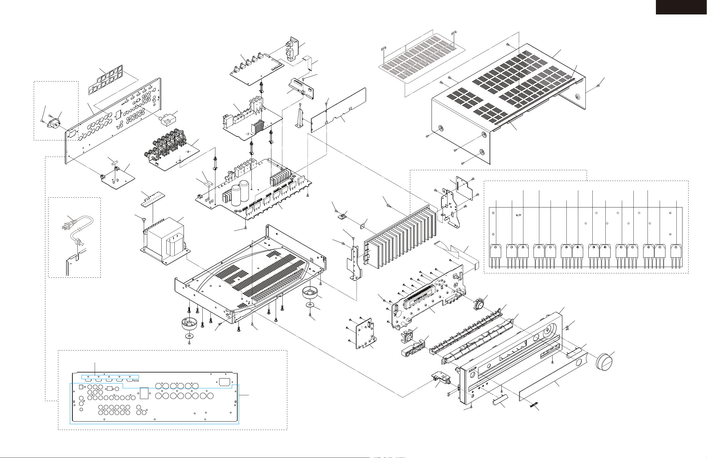
EXPLODED VIEW
EXPLODED VIEW(OVERALL)
A099
MDS,MDF only
SCREW
3TTF+10B(3BC)
x 2 pcs.
P900
A101
F901
U0063
U009
U0040
F6402
F6401
U0080
U0062
U0065
U0041
P8001
SCREW
3TTB+8B(3BC)
SCREW
3TTB+8B(3BC)
x 3 pscs.
U0030
HT-R592
A709
A723
3TTB+8B(3BC)
x 9 pcs.
A721
MDC only
U0031
Except MDS, MDF type
P901
e.g. MDC type
SCREW
3P+6FN(3BC) x 5 pcs.
U0014
SCREW
4TTC+8C(3BC)SR
x 4 pcs.
Rear Panel
T901
SCREW
3TTB+8B(3BC)
x 2 pcs.
SCREW
3TTB+8B(3BC)
U0010
SCREW
3TTB+8B(3BC)
x 2 pcs.
SCREW
3TTB+8B(3BC)
SCREW
3TTB+8B(3CM)SR
SCREW
3TTB+8B(3BC)
x 4 pcs.
A003
A005
SCREW
3TTB+8B(3BC)
x 4 pcs.
SCREW
3SMS8W.SW+14B(CU)
x 14 pcs.
U0011
U0012
SCREW
2.6TTB+8B(3BC)
x 22 pcs.
U0061
A225
U0060
A211
P701
Q6056
A227
Q6055
Q6066
A213
A212
Q6065
Q6054
Q6053
Q6063
Q6064
Heatsink
A201
SCREW
3TTB+8B(3BC) x 4 pcs.
A214
Q6051
Q6061
A701
Q6050
Q6060
Q6052
Q6062
SCREW
3TTB+8B(3BC)
x 27 pcs.
U0064
SCREW
3TTB+8B(3BC)
x 3 pcs.
A214
A202
A205
Page 18
TX-NR525/626/ HT-R592/ DTR-30.5
TX-NR525/626/ HT-R592/ DTR-30.5
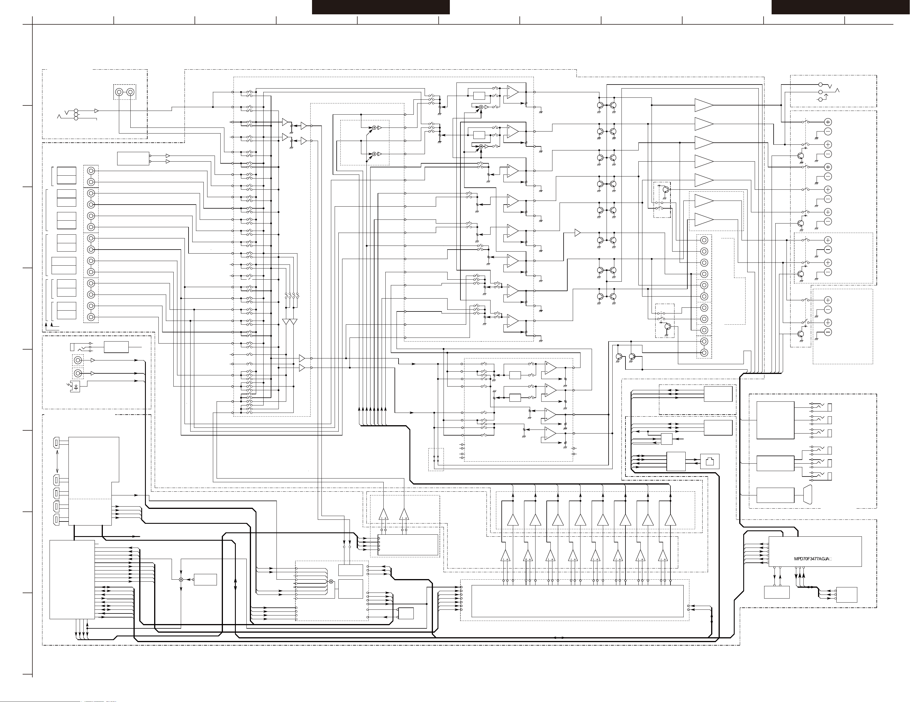
SCHEMATIC DIAGRAMS-01(PART-1)
BLOCK DIAGRAM AUDIO SECTION
MAIN R
REC R
SUB L
REC L
SPRLZ2
SPRLSB
SPRLCS
MAIN L
SBRELAY
PRERELAY
SBZ2MUT
SPRLF
AMUT
Z2MUTE
Q7401
FRONT BOARD
MIC DET
MIC AMP
MIC
OPT1
SPI
FRONT RIGHT
Subwoofer
AV=+20dB
(FL/FR)
(CT/SW)
(SL/SR)
(BL/BR)
8ch DAC
LPF
+6dB
LPF
+6dB
LPF
+6dB
+6dB
LPF
+6dB
LPF
+6dB
LPF
+6dB
LPF
+6dB
LPF
SPI
TRANSMITTERS
RS232
IR
REMOTE SENSOR
RS232
CENTER
SURR. LEFT
SURR. RIGHT
FRONT RIGHT
AUX IN
(FRONT IN)
XOUT
XTAL-X501
5MHz
XIN
BCK NET
LRCK NET
DATA NET
MCK NET
CX LRCK
CX SCLK
DSP FLR
DSP SLR
DSP CSW
DIR LRCK
DIR FLR
DSP SBLR
DIR BCK
ADSP MCK
OVERCURRENT DET
MDIO Controls
USB EN VBUS
RMII Controls
RMII RX
RMII TX
VBUS
DATA+
DATA-
SPI
SP to Micom
COAX 2
12V TRIDDER
CONTROL
SPI to Micom
HDMI BCK
HDMI LRCK
HDMI FLR
OPT2
OPT1
COAX2
COAX1
HDMI MCK
SURR. BACK
LEFT
XTAL
RJ-45
EtherMAC
MDIO Controls
RMII Controls
RMII TX
RMII RX
HI SIDE SW
USB EN VBUS
OVERCURRENT DET
+5V
DATA-
DATA+
VBUS
YKF45-0029N
USB
DATA-
DATA+
VBUS
YKF45-0029N
USB
USB VBUS
IN7
DSP
DSP
HDMI MCK
HDMI BCK
HDMI LRCK
HDMI FLR
SPDIF
OUT
OUT
IN1
IN2
HDMI Tx
HDMI Rx
Q3001: D830K
AVD7623Q8101
Q8302
Q8201
Q8101
X-TO
X-Tl
MCLK
XTAL
X171
LPF
LPF
+6dB
+6dB
DIG SD1
DIG SD0
DIG CLK
BCK NET
LRCK NET
DATA NET
MCK NET
DIR LRCK
DIR FLR
DIR BCK
DIR MCK
2ch ADC
DIR
Q301
Q1002
2ch DAC
Q304
CENTER
Q4102
Q4101
Q4107
Q4104
Q4103
(SL/SR)
(CT/SW)
(FL/FR)
(BL/BR)
DSP SLR
DSP CSW
CX SCLK
CX LRCK
DSP SBLR
DSP FLR
DIR MCK
DIG CLK
DIG SDO
VMSDO
VMCLK
VMSDI
+6dB
LPF
+6dB
LPF
+6dB
LPF
+6dB
+6dB
LPF
+6dB
LPF
+6dB
LPF
LPF
+6dB
FR
FL
C
SW
SR
SL
SBR
SBL
LPF
DIGSDI
DIGSDO
DIGCLK
CLK
SDO
SDI
CLK
SDO
SDI
SPI
EEPROM
RI
INTERFACE
COAX 1
RI
LEFT
ZONE2 SPK
(HDMI SLC)
(HDMI SDA)
HT-R592
TX-NR525
TX-NR626
DTR-30.5
TX-NR626/ DTR-30.5
HT-R592
TX-NR525
HT-R592
DTR-30.5 ONLY
DTR-30.5
TX-NR626
TX-NR525
T5, T6-->
<--H59
<--H59
T5, T6-->
BD/DVD
VCR/DVR
<--H59
T5, T6-->
(BD/DVD)
<--H59
T5, T6-->
VCR/DVR OUT
(CBL/SAT)
CBL/SAT
<--H59
T5, T6-->
GAME
<--H59
TVCD
<--H59
T5, T6-->
(TV/CD)
(PHONO)
T6-->
<--H59/T5
4P 4P 4P
2P 2P
IR IN
IR IN
IR OUT
12V TRIGGER A
12V TRIGGER B
12V TRIGGER C
TONE
TONE
INVERTING
INVERTING
FR
CEN
SL
SR
SW
SBL
Downmix
FL/FR -12dB
SW +3.5dB
SBR
FL
Q4003
FRONT LEFT
SBR
SURR. RIGHT
SURR. BACK.LEFT
SURR. BACK.RIGHT
SURR. LEFT
TUNER PACK
from Micom
Q4001
SURR. BACK
RIGHT
DTR-30.5
TX-NR525 Series
TX-NR626 Series
BAHDM1337
BAHDM1347
BAHDM1357
SPEAKER TERMINALS
MICOM
Q705
HT-R592
TX-NR525
TX-NR626
DTR-30.5
Q1004
Q1005
Q701
Z2NET R
Z2NET L
ONLY
TX-NR525
TX-NR626
DTR-30.5
Q351
HEADPHONES
HT-R592
ONLY
TX-NR626
DTR-30.5
(SR)
R2A15218FP
ZONE2 SPK
RIGHT
POWER AMPLIFIER
SURR L
SURR R
+29dB
+29dB
+29dB
+29dB
+29dB
+29dB
+29dB
Q4111
Q4112
Q4113
Q4114
Q4105 Q4115
Q4116Q4106
FL
FR
C
SW1
SBL
SBR
SR
Z2L OUT
Z2R OUT
SW2
ZONE2 L
ZONE2 R
DTR-30.5
ONLY
DTR-30.5
ONLY
TX-NR626
DTR-30.5
ONLY
Q4117
(SBR)
(SBL)
(SL)
(FR)
CEN
SR
SW
SBL
SL
PREOUT
DTR-30.5
ONLY
(GAME)
T5, T6-->
(PC)
Z2 L
Z2 R
Q4100
Q4110
Zone2 SPK
HT-R592
(LEVER TYPE)
BATRM1335 2/2
TX-NR626
DTR-30.5
ONLY
Zone2 SPK
(Banana TYPE)
HT-R592
Q701
TX-NR525
SR DIRECTION
SL DIRECTION
C DIRECTION
SW DIRECTION
FL DIRECTION
FR DIRECTION
SBL DIRECTION
SBR DIRECTION
Q4303 Q4302
TONE
TONE
Zone2 in(R-ch)
EXCEPT D3
R2A15218FP
Q4301
ZONE FUNCTION
DR-30.5 ONLY
(FL-OUT)
(FR-OUT)
(SBR-OUT)
(SBL-OUT)
Z2 out(L-ch)
Z2 out(R-ch)
Z2 R Line/preout
Zone2 in(L-ch)
SR
SL
SBR
SBL
SW
C
FL
FR
FR
FL
(FL)
MODEL NO. HT-R592/ TX-NR525/ HT-RC550/ TX-NR626/ HT-RC560/ DTR-30.5
BLOCK DIAGRAM (PART-1) AUDIO SECTION
2013. 01. 10.
FRONT LEFT
BATRM1089 1/1
BATRM1335 1/2
(SR)
(SL)
(FL)
(FR)
(SBR)
(SBL)
(FR-IN2)
(IN-R9)
(SBR-IN)
(SUBRC-IN)
(FL-IN2)
(IN-L9)
(SUBLC-IN)
(SBL-IN)
BATRM1089 1/2
BADG1345 1/2
BADG1345 2/2
NC
(NC)
NC
SL
R L
L
R
L
R
L
R
L
R
L
R
L
R
L
R
L
R
L
R
L
R
L
R
L
R
L
R
L
R
L
R
L
R
L
R
Z2 L Line/preout
HT-R592
HT-R592 Series
MPD70F3746GJ
LTAD
RTAD
PCM1754DBQR
PCM1690DCAR
DTR-30.5
TX-NR626
HT-R592
TX-NR525
PCM1681PWPR
PCM9211PTR TX-NR525
HT-R592
TX-NR626
DTR-30.5
PCM9211PTR
SII9573CTUC
SII9573CTUC
PS331TQFP64GTR
TX-NR525
TX-NR626/ DTR-30.5
(REPEATER)
TRANSCEIVER
HDMI
Q201: DA808K
BADIS1370 1/4
BADIS1330 1/5
BADIS1340 1/4
BADIS1370 2/4
BADIS1330 2/5
BADIS1340 2/4
BADIS1370 3/4
BADIS1340 3/4
BADIS1330 4/5
BADIS1330 3/5
BADIS1370 4/4
BADIS1330 5/5
BADIS1340 4/4
1 12
132
6
21
20
17
18
23
24
12
11
8
9
14
15
5
3
6
73
86
81
82
85
72
78
79
70
71
68
69
66
67
64
65
62
76
75
91
90
59
58
61
60
63
55
54
46
47
40
96
39
100
37
99
36
44
97
41
38
98
43
93
42
95
45
94
83
84
2
43
78
44
100
42
79
45
99
98
97
40
41
11
9
3
5
21
23
A
1
2
3
4
5
B C D E F G H
6
7
8
I
J K
Page 19
HT-R592
A
1
2
3
4
B C D E
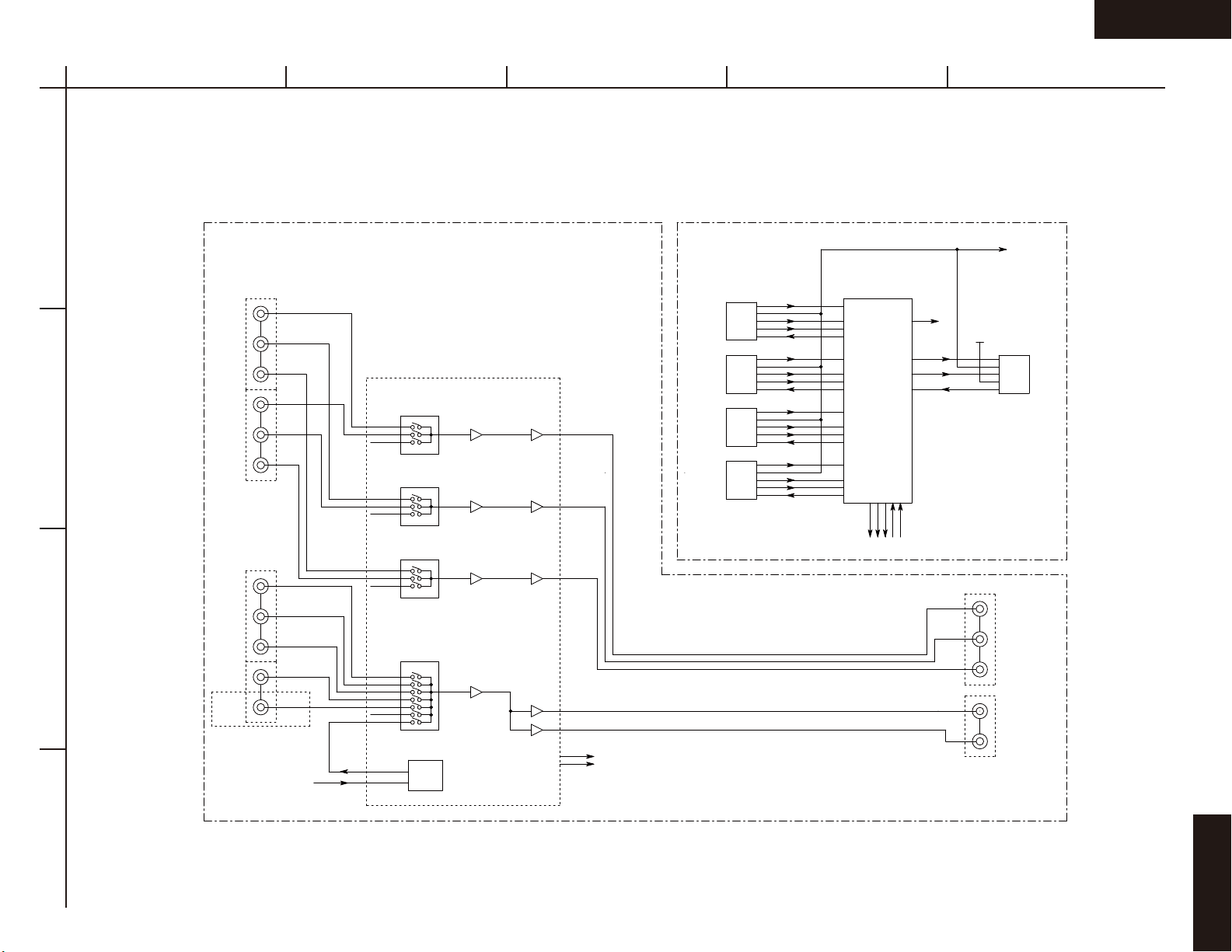
SCHEMATIC DIAGRAMS-02(PART-2)
BLOCK DIAGRAM VIDEO SECTION
TMDS
TMDS
HP DET
TMDS
HP DET
TMDS
HP DET
TMDS
HP DET
CEC
CEC
DDC
DDC
RPWR
+5V
HPD
TMDS
CEC
CEC
DDC
DDC
RPWR
+5V
HPD
TMDS
CEC
CEC
DDC
DDC
RPWR
+5V
HPD
TMDS
CEC
CEC
DDC
DDC
RPWR
+5V
HPD
Rx Port B Tx
Q8101
ADV7623
HDMI 4Rx Tx
Rx Port C
Rx Port D
ARC S/PDIF
I2C
TMDS
DDC
HPD
I2S
I2S
S/PDIF
S/PDIF
Y1
CB1
CR1
Y2
Yin1
CB2
CR2
COMPONENT VIDEO INPUT
Yin2
Yin3
PBin1
PBin2
PBin3
NJM1328
PY
PB
6dB
6dB
DRV
DRV
HDMI IN4 Rx Port A
HDMI IN3
HDMI IN2
HDMI IN1
CEC
+5V Hot Plug
TMDS
CEC
DDC
+5V
HP DET
HDMI OUT
PRin1
PRin2
DVD
VCR/DVR
CBL/SAT
GAME/TV
AUX1
(FRONT)
COMPOSITE VIDEO INPUT
UPort
PRin3
Vin2
Vin3
Vin4
Vin5
Vin1
Vin6
Vin7
ISOOUT
ISOIN
ISO
PR
6dB
CV
6dB
DRV
Y
COMPONENT
CB
OUT
CR
DRV
DRV
I2C
MUTE
COMPOSITE VIDEO OUTPUT
MONITOR
VCR/DVR
HT-R592
Model No. HT-R592
SCHEMATIC DIAGRAM (PART-2) BLOCK DIAGRAM(VIDEO)
08-11-2012
Page 20

HT-R592
A
1
2
3
4
B C D E
SCHEMATIC DIAGRAMS-03(PART-3)
BLOCK DIAGRAM DIGITAL AUDIO SECTION
S/PDIF
INPUT
XTAL
24.576MHz
XTAL
11.2896MHz
4
39
15
16
DIR
4
MPIO_A1
XTI
MPO0
MPO1
256x48K
256x44.1K
DIVIDE
Q301
PCM9211
MPIO_B214MPIO_B3
MPIO_B0
MPIO_B1
11
12
13
No USE
DIR_MCK
68
Q8101
MCLK_IN
SCLK_IN
AP5_IN
AP1_IN
69
70
76
CX_SCLK
CX_LRCK
DSP_FLR
HDMI Tx
HDMI Rx
MCLK_OUT
SCLK_OUT
AP5_OUT
AP1_OUT
AP2_OUT
AP3_OUT
AP4_OUT
AP0_OUT
95
94
88
89
90
91
87
HDMI_BCK
HDMI_LRCK
HDMI_FLR
HDMI_SLR
HDMI_CSW
HDMI_SBLR
HDMI_SPDIF
HDMI_MCK
96
USB
HDMI_SPDIF
DIR/ADC
DIR
MPIO_CMPIO_B
MPIO_C2
MPIO_C1
MPIO_C0
7
9
8
10
HDMI_FLR
HDMI_LRCK
HDMI_BCK
HDMI_MCK
AUXIN1
MPIO_C3
MAIN OUT
SCKO19BCK18LRCK
20
DIR_BCK
DIR_LRCK
DIR_MCK
ADC
DOUT
17
DIR_FLR
A
D
C
DOMAIN
Q302
PCM1681
DAC
ANALOG
LRCK
DATA3
SCK
DATA2
BCK
DATA1
8
6
DSP_FLR
CX_LRCK
12
11
DSP_SLR
DSP_CSW
DATA4
13
DSP_SBLR
7
5
CX_SCLK
DIR_MCK
Q201
DA808
DIR_MCK
CX_SCLK
CX_LRCK
DSP_FLR
DSP_SLR
DSP_CSW
DSP_SBLR
DIR_MCK
DIR_BCK
DIR_LRCK
DIR_FLR
HDMI_LRCK
HDMI_SLR
HDMI_CSW
HDMI_SBLR
HDMI_SPDIF
USB DATA
160
AHCLKX1/EPWM0B/GP3[14]
126
ACLKX0/ECAP0/APWM0/GP2[12]
127
AFSX0/GP2[13]/BOOT[10]
111
AXR0[0]/AFSR2/GP3[0]
112
AXR0[1]/ACLKX2/GP3[1]
113
AXR0[2]/AXR2[3]/GP3[2]
115
AXR0[3]/AXR2[2]/GP3[3]
125
AHCLKX0/AHCLKX2/USB_REFCLKIN/GP2[11]
130
ACLKR0/ECAP1/APWM1/GP2[15]
131
AFSR0/GP3[12]
116
AXR0[4]/GP3[4]
121
AXR0[8]/GP3[8]
117
AXR0[5]/AFSX2/GP3[5]
118
AXR0[6]/ACLKR2/GP3[6]
122
UART1_RXD/AXR0[9]/GP3[9]
22
EMA_OE/UHPI_HDS1/AXR0[13]/GP2[7]
123
UART1_TXD/AXR0[10]/GP3[10]
124
AXR0[11]/AXR2[0]/GP3[11]
137
USB0_DP
138
USB0_DM
DSP
HDMI Input S/PDIF & Analog
I2S DSD HBR
Master Clock
N/A LR Clock
DSD0B
I2S0 I2S0
DSD2B
I2S1
DSD1A
I2S2
DSD1B
I2S3
DSD2A
DSD0A
Bit Clock
LR ClockLR Clock
HBR1st
N/AN/A
HBR2nd
HBR3rd
HBR4th
N/AN/A
Input
N/A
HT-R592
Model No. HT-R592
SCHEMATIC DIAGRAM (PART-3) BLOCK DIAGRAM (DIGITAL AUDIO)
08-11-2012
Page 21

TX-NR525/626/ HT-R592/ HT-RC550/560/ DTR-30.5 TX-NR525/626/ HT-R592/ HT-RC550/560/ DTR-30.5
SCHEMATIC DIAGRAMS-04(PART-4)
ASP SECTION
GND_T U
TU_RI
TU_LI
TU_SC L
TU_SC L
TU_SD A
TU_SD A
TU_RS T
GND_C H
SBL+
SBR+
SL+
SR+
SW+C+FL+
FR+
VOLH
VOLH
IPROT ECT
IPROT ECT
VPROT ECT
VPROT ECT
SEC1H
SEC1H
DAC_S W
DAC_C T
DAC_S R
DAC_S L
DAC_S BR
DAC_S BL
DAC_F R
DAC_S R
DAC_S L
DAC_C T
DAC_S BR
DAC_S BL
DAC_F L
DAC_S W
MICOU T
LTAD
DAC_F R
DAC_F L
SR_IN
SL_IN
PRRLF
SBREL AY
RTAD
Z2R+
Z2L+
Z2NET _R
Z2NET _L
Z2NET _R
Z2NET _L
S1L+
S1L-
VOLCL K
Z2VOL CLK
SBZ2M UT
AMUT
+5VTU
FR+
FL+
SW+
C+
SR+
SL+
SBR+
Z2R+
SBL+
Z2L+
L_IN
R_IN
VOLDA TA
C_IN
AUX_R
AUX_L
Z2MUT
+24V
+15V
-15V
SBR_I N
SBL_I N
GND_A MP
GND_A MP
151J
*C443 4
151J
*C443 3
221J
C4131
102K
C4401
102JC42 05
102JC4204
101JC40 91
50V
101JC40 90
50V
C4402
NC
C4405
NC
102KC4400
102J
*C400 0
221J
C4010
221J
C4009
221J
C4013
221J
C4014
102J
*C443 7
221J
*C401 5
103K
*C421 1
103K
*C420 0
102J
*C421 9
221J
*C403 5
221J
*C403 6
103K
*C421 7
221J
*C402 7
221J
*C403 1
221J
*C403 0
221J
C4025
221J
C4032
221J
*C430 6
221J
*C430 5
102J
*C421 6
50V
221J
*C401 6
102J
*C400 2
102J
*C400 1
471J*C454 0
471J*C454 1
151J*C453 8
151J
*C453 9
152J
*C453 3
152J
*C453 2
101J
*C454 2
104Z
*C454 9
104Z
*C454 8
151J
*C443 8
151J
*C443 9
151J
*C443 5
151J
*C443 6
101J
*C454 3
221J
*C402 2
221J
*C402 1
221J
*C403 3
221J
*C403 4
102J
*C421 8
102J*C432 4
220J
C4093
*C400 5
NC
220J
C4094
*C442 6
332J
*C442 2
332J
*C443 2
221J
*C442 1
332J
*C442 0
332J
*C442 3
332J
*C453 4
123J
*C453 5
123J
*C453 7 3 32J
*C453 6 3 32J
*C442 4
332J
*C401 9
221J
*C402 0
221J
C4003
221J
C4004
221J
*C443 1
221J
*C443 0
221J
*C430 9
223J
*C431 3 823J
*C431 1 474J
*C431 2
474J
*C431 0 223J
*C431 4
823J
*C401 7
221J
*C401 8
221J
C4132
103J
C4300
334J 50 V
*C442 8
332J
*C442 9
332J
*C442 5
332J
*C442 7
332J
C4100
47u 50V
C40724 7u 50V
C40754 7u 50V
C4107
47u 50V
C40764 7u 50V
C40714 7u 50V
C40774 7u 50V
*C407 847u 50V
*C407 947u 50V
C40734 7u 50V
C40744 7u 50V
C4175 470u 16V
*C431 8 4 70u 16V
*C452 5
47u 25V
*C446 6
47u 25V
*C418 6
220u
25V
*C452 9
47u 25V
C4172
220u
25V
C406047u
25V
C4061
47u 25V
*C411 1
220u 25V
*C452 8
47u 25V
*C410 6
47u
50V
C4102
47u 50V
C4166
220u 25V
C4173
220u
25V
*C454 6
47u 25V
*C454 7
47u
25V
*C411 0
220u 25V
*C418 4
220u 25V
*C454 4
10u
50V
*C454 5
10u
50V
*C418 5
220u 25V
*C455 0
220u
10V
*C455 1
220u
10V
*C418 7
220u
25V
C4086
47u 25V
C4085
47u 25V
C4167
220u 25V
C4109
47u
50V
C4209
47u 25V
C4051 47u 25V
C4052 47u 25V
C4053
47u 25V
C4404
47u 25V
*C453 1
47u 25V
*C453 0 47 u 25V
C4174 470u 16V
C4130 47u
50V
C4054 4 7u 25V
*C431 6 4 7u 50V
*C430 8
47u 50V
*C430 7
47u 50V
*C431 9 4 70u 16V
*C433 0 4 7u 25V
*C432 9 4 7u 25V
*C432 8 4 7u 25V
*C432 7 4 7u 25V
*C432 5 4 7u 25V
*C432 6 4 7u 25V
*C452 2
47u 25V
*C452 7
47u 25V
C4171
10u
50V
C4170
10u
50V
C40704 7u 50V
C4055 4 7u 25V
*C431 7
47u 50V
C4210
47u 25V
C4057 4 7u 25V
C4056 4 7u 25V
C4103
47u 50V
C4101
47u 50V
C4104
47u 50V
C4301
1000u 35V
C4302
470u 35V
C4108
47u
50V
*C410 5
47u
50V
C4050 47u 25V
P5503 B
1 2 3 4 5 6 7
P101B
1 2 3 4 5 6 7 8 9
P5504 B
1 2 3 4 5 6 7 8 9 10 111 213
P5502 B
1 2 3 4 5 6 7 8 9 10 111 213 1415 161 718 1920
D4303
RL1N4 003
D4304
RL1N4 003
D4305
RL1N4 003
*D420 1
DA2J1 0100
*D420 0 DA 2J10100
*D421 9
DA2J1 0100
D4300
RL1N4 003
*D420 8
DA2J1 0100
*D421 8
DA2J1 0100
*D421 7
DA2J1 0100
D4302
RL1N4 003
D4301
RL1N4 003
*D420 6 D A2J10100
*D430 7 D A2J10100
*D421 6 D A2J10100
*D430 8 D A2J10100
*D420 9
DA2J1 0100
*D420 7
DA2J1 0100
*D431 9 DA 2J10100
*D430 9 DA 2J10100
*D417 4 D Z2J068M0L
*D417 1
DZ2J0 75M0L
D4400
DZ2J0 56M0L
*D417 3 D Z2J068M0L
*D417 2
DZ2J0 75M0L
Q4170 A RAD-196
1
2
3
4
*Q414 5
NJM45 80M-D
OUT
7
-6+
5
+V
8
*Q414 8
NJM45 80M-D
OUT
7
-6+
5
+V
8
Q4130
NJM45 80M-D
OUT
7
-
6
+
5+V8
*Q453 0
NJM45 80M-D
OUT
7
-
6
+
5
+V
8
Q4003
NJM45 80M-D
OUT
7
-
6
+
5
+V
8
*Q414 2
NJM45 80M-D
OUT
7
-6+
5
+V
8
*Q414 0
NJM45 80M-D
OUT
7
-6+
5
+V
8
*Q414 3
NJM45 80M-D
OUT
7
-6+
5
+V
8
*Q453 0
NJM45 80M-D
OUT
1
-
2
+
3
-V
4
*Q414 2
NJM45 80M-D
OUT
1
-2+
3
-V
4
Q4003 NJM45 80M-D
OUT
1
-
2
+
3
-V
4
*Q414 0
NJM45 80M-D
OUT
1
-2+
3
-V
4
*Q414 3
NJM45 80M-D
OUT
1
-2+
3
-V
4
*Q414 5
NJM45 80M-D
OUT
1
-2+
3
-V
4
Q4130
NJM45 80M-D
OUT
1
-
2
+
3
-V
4
*Q414 8
NJM45 80M-D
OUT
1
-2+
3
-V
4
Q4001
R2A15218FP
NC1 1
SL-OU T 9
SLC 8
SWC 1 4
NC2 1 3
SRC 1 2
AGND3 10
AGND1 4
3
SBL-O UT
AGND2 7
SBRC 6
SBLC 2
SBR-O UT 5
SR-OU T 11
SW-OU T 15
AGND4 16
C-OUT 17
CC 18
AGND5 19
FLC 2 0
FL-OU T 21
AGND6 22
FR-OU T 23
FRC 2 4
NC3 2 5
BASS_ L1
26
BASS- L2
27
TREL
28
NC4
29
AVCC
30
NC531BASS- R132BASS- R233TRER34NC635SBL-I N236SBR-I N237C-IN238SW-IN 239SL-IN 240SR-IN 241FL-IN 242FR-IN 243SBRC- IN44SBLC- IN45SUBL46SUBR47DGND48DATA49CLOCK
50
MUTE
51
AVEE
52
NC7
53
ADCL
54
ADCR
55
AGND7
56
NC8
57
IN-R1
58
IN-L1
59
IN-R2
60
IN-L2
61
IN-R3
62
IN-L3
63
IN-R4
64
IN-L4
65
IN-R5
66
IN-L5
67
IN-R6
68
IN-L6
69
IN-R7
70
IN-L7
71
IN-R8
72
IN-L8
73
NC9
74
INRA/ RECR1
75
INLA/ RECL1
76
NC10
77
IN-R9
78
79
IN-L9
NC11
80
8182838485
86
NC1287NC1388NC14
89
RECR390RECL3
91
NC15
92
FL-IN 193FR-IN 1
94
C-IN1
95
SW-IN 1
969798
99
100
*Q430 1
R2A15 218FP
NC1 1
SL-OU T 9
SLC 8
SWC 1 4
NC2 1 3
SRC 1 2
AGND3 10
AGND1 4
SBL-O UT 3
AGND2 7
SBRC 6
SBLC 2
SBR-O UT 5
SR-OU T 11
SW-OU T 15
AGND4 16
C-OUT 17
CC 18
AGND5 19
FLC 2 0
FL-OU T 21
AGND6 22
FR-OU T 23
FRC 2 4
NC3 2 5
BASS_ L1
26
BASS- L2
27
TREL
28
NC4
29
AVCC
30
NC531BASS- R132BASS- R233TRER34NC635SBL-I N236SBR-I N237C-IN238SW-IN 239SL-IN 240SR-IN 241FL-IN 242FR-IN 243SBRC- IN44SBLC- IN45SUBL46SUBR47DGND48DATA49CLOCK
50
MUTE
51
AVEE
52
NC7
53
ADCL
54
ADCR
55
AGND7
56
NC8
57
IN-R1
58
IN-L1
59
IN-R2
60
IN-L2
61
IN-R3
62
IN-L3
63
IN-R4
64
IN-L4
65
IN-R5
66
IN-L5
67
IN-R6
68
IN-L6
69
IN-R7
70
IN-L7
71
IN-R8
72
IN-L8
73
NC9
74
INRA/ RECR1
75
INLA/ RECL1
76
NC10
77
IN-R9
78
IN-L9
79
NC11
80
8182838485
86
NC1287NC1388NC14
89
RECR390RECL3
91
NC15
92
FL-IN 193FR-IN 1
94
C-IN1
95
SW-IN 1
969798
99
100
Q4170
78M15 HF(NJM78 M15FA)
I
G
O
Q4171
79M15 HF(NJM79 M15FA)
G
IO
P4002
1
2
3
4
5
6
7
P4003
1
2
3
4
5
6
7
P4010
1
2
3
4
5
6
7
P4004
1
2
3
4
5
6
7
P4011
1
2
3
*P400 1
1
2
3
7
*P400 8
1
2
3
7
*P400 9
1
2
3
7
*P400 7
1
2
3
7
*J467 7
*J448 5
J4188
NC
*J467 8
J4185
NC
*J448 4
*J465 3
S1L+, S1L-
+24V, GND_AMP
IPROT ECT,SEC1 H,VOLH,V PROTECT
AMPSI G_IN
*R423 0 0
*R421 3 0
*R430 2
0
*R422 1
0
*R423 1
@valu e
*R430 3
0
*R462 7 0
*R422 2
0
R4289 0
R4225
0
*R462 9 0
*R421 2 0
R4211 0
*R462 2 0
*R422 6
0
*R422 3
0
*R452 4
0
*R422 8
0
*R422 9
0
*R462 5 0
*R462 8 0
*R422 7
0
R4408
*R466 6 0
*R430 5
100
*R407 7
22k
R4309
2.2k
R4189
220K
*R405 9
100k
*R430 6
@valu e
R4294 220K
R4308
2.2k
*R405 5
220K
R4181 220K
R4293 220K
*R403 4
100
R4311
220K
*R430 4
100
R4101
220K
R4014
330
*R403 0
100
*R403 1
100
*R443 4
15k
*R410 4
220K
*R413 9
100k
R4100
220K
R4053
100k
R4182 220K
R4032
100
*R407 2
2.2k
*R402 5
2.2k
R4026
100
R4054
100k
R4091
22k
R4099
22k
*R411 2
2.2k
R4088 2.2k
*R442 0
4.7k
*R407 1
220K
R4403 100k
*R416 10.22
1W
R4013
330
R4406
680
*R445 1
560
*R445 0
560
*R400 2
330
*R400 1
330
*R401 9
330
*R445 3
560
*R404 2
56k
*R404 1
56k
*R453 0
100k
*R453 1
100k
*R445 7
560
*R445 4
560
R4078 47k
R4131
47k
R4079 47k
*R442 3
4.7k
*R442 1
4.7k
*R442 7
4.7k
*R453 5 270k
*R453 4 270k
*R453 6 2 2k
*R453 7 2 2k
*R453 8
1.2k
*R453 9
1.2k
*R442 2
4.7k
R4097
3.3k
*R453 2
560
*R453 3
560
R4058
100k
*R454 2
100k
*R442 4
4.7k
R4093
3.3k
*R454 1
100
*R454 0
100
R4407
33k
*R443 3
15k
*R443 7
15k
*R454 5
22
R4107
220K
*R410 2
220K
*R411 5
270
*R410 5
220K
*R410 6
220K
R4132
15k
R4090 12k
R4546 220K
R4547 220K
*R454 4
22
R4098 12k
R4133
1.2k
*R406 0
100k
R4096
330
*R401 5
2.2k
R4087 2.2k
*R452 6
100k
*R452 5
100k
R4166 2 2
R4069 1 00k
*R445 6
560
*R445 5
560
*R418 5
4.7
1W
*R418 4
470
*R418 3
470
R4127
100
R44011kR4400
1k
*R443 8
4.7k
*R444 6
330
*R444 5
330
*R442 6
4.7k
*R442 5
4.7k
*R443 6
15k
*R443 5
15k
R4082 100k
*R413 8
100k
*R444 7
330
*R452 7
100k
R4057
100k
*R407 0
220K
R4049
100k
*R416 20 .22
1W
*R416 30 .22
1W
*R418 8
8.2
1W
*R418 6
1
1W
eula
v@6234R*
*R405 6
220K
*R454 3
100k
*R452 9
100k
*R452 8
100k
R4295 220K
*R444 9
*R412 3 100
*R445 9
5.6k
*R442 9
3.3k
*R445 8
5.6k
*R442 8
3.3k
*R419 9
22
*R443 9
4.7k
R4167
22
*R432 0
220K
*R444 2
330
*R444 4
330
*R431 7
2.2k
*R418 0 2 20K
*R431 8
2.2k
*R444 3
330
R4130
220
R4043
100k
*R432 7 10
*R410 8
220K
*R431 6
100k
*R410 9
220K
R4044
100k
*R419 8
22
*R443 1
15k
*R443 0
15k
*R401 6
2.2k
*R416 00 .22
1W
R4134 10 k
*R431 4
1.8k
R4095 10k
R4094 10k
*R443 2
15k
*R431 5
1.8k
*R445 2
560
*R432 1
220K
*R444 0
330
*R444 1
330
*R407 4
22k
*R407 3
22k
R4018
330
R4003
330
*R412 6 100
*R412 5 100
*R412 4 100
*R444 8
R4402 100k
*R412 1 100
*R412 0 100
*R412 2 100
*R416 8
22
*R416 9
22
R4404
680
*R402 7
100
*R403 6
100
*R411 3
2.2k
*R411 1
2.2k
*R411 0
2.2k
R4017
330
*R403 5
100
*R407 5
220K
R4092
330
*R402 0
330
R4310
220K
*R411 6
270
R4010
330
R4296 220K
R4117
270
R4009
330
*R428 4
470
*R428 3
470
*R411 4
2.2k
*R407 6
220K
R4190
220K
*R403 3
100
R4292 220K
*R430 7
@valu e
*R452 2
100k
R4004
330
R4050
100k
*R410 3
220K
*R417 4
1W
68
R4409
1W100
R4405
1W100
*R418 7
1W
10
*R417 5
1W
68 *R4 177
1W
47
*R417 6
1W
47
*RL42 0
NRL-2 P2A-DC24 -174
1
1
3
3
9
9
445
5
12
12
10
10
8
8
*RL42 1
NRL-2 P2A-DC24 -174
1
1
3
3
9
9
445
5
12
12
10
10
8
8
TP433 6
TP409 1
TP551 2
TP439 1
TP435 5
TP435 4
TP437 6
TP437 5
TP438 1
TP438 4
TP438 3
TP438 2
TP438 6
TP417 0
TP408 2
TP551 4
TP409 0
TP417 2
TP433 7
TP407 7
TP431 7
TP434 7
TP434 6
TP406 4
TP406 5
TP408 1
TP417 1
TP434 1
TP402 8
TP402 7
TP402 6
TP550 3
TP101
TP550 4
TP407 4
TP439 0
TP434 0
TP438 5
TP403 2
TP403 3
TP403 4
TP431 1
TP431 5
TP430 9
TP509
*Q418 4
Q4400
2SC28 81-Y(TE1 2L,CF)
Q4103
RN144 1
Q4100
RN144 1
*Q411 3
RN144 1
Q4107
RN144 1
*Q410 5
RN144 1
*Q411 1
RN144 1
Q4102
RN144 1
*Q411 2
RN144 1
Q4117
RN144 1
*Q410 6
RN144 1
*Q411 6
RN144 1
Q4302
RN144 1
Q4104
RN144 1
Q4101
RN144 1
Q4303
RN144 1
*Q411 0
RN144 1
*Q411 4
RN144 1
*Q411 5
RN144 1
*Q420 1
KRC10 2S
*Q420 0
KRC10 2S
*Q418 5
P5508
1234
*P551 0B
1234
*P551 1B
123
4
FL/FR :-12dB
Downm ix
(SR D IRECT IN )
(SL D IRECT IN )
(C DI RECT IN)
GND
BD To BD
Z2MUT
Subwo ofer + 20dB
C_OUT
BD To BD
SR_OU T
SL_OU T
SBL_O UT
SBR_O UT
FR_OU T
FL_OU T
SW_OU T
AMUT
Z2R
Z2L
+23V
-23V
R
L
R
L
R
L
R
L
L
R
TVCD
(TV/ CD)
GAME
(PC)
CBL/ SAT
(GAM E)
VCR/ DVR OUT
(CBL /SAT)
VCR/ DVR
-50mA max
-35mA typ
+50mA max
+35mA typ
<--H5 9
<--H5 9
<--H5 9
<--H5 9
<--H5 9
<--H5 9
X
220K
2.2K
L
GND_C H
X
BAAF-1310(1/2)
V
(BD/ DVD)
FROM BAETC-13 79(PART1 0):HT-R5 92
R
ONLY
D
4P
2PNM
Table :V
C4015 ,16
R4015 ,16
R4055 ,56
D3 ON LY
ASP/AMP
Table :X
CHISS IS HOLE
OTHER D3
(PART 5)
TO MA IN AMP
FLFR CSW SR SL SBLSBR
LIST
LISTLIST LISTLI ST LISTLIST LIS T
LIST
LIST
LIST
LIST
LIST: 0ohm
LISTLI ST
LIST L IST
D3
(PART 5)
TOMAI NAMP
SBZ2M UT
(ASPG ND)
D3
TUNER 2.5mm F FC CABLE
TUNER PACK
LIST
LIST
D3
LIST: 0ohm
P
LIST
LIST
LIST
LIST
MODE L NO. HT-R5 92/ T X-NR525/ HT -RC55 0/ TX- NR626 / HT- RC560/ DTR- 30.5
SCHE MATIC DIAGR AM(PA RT-4) ASP
2013 .01.1 1
T6
T5,T6 -->
T5,T6 -->
T5,T6 -->
T5/T6 -->
T5,T6 -->
T5,T6 -->
O
CONVE RSION
FROM BAETC-13 79(PART1 0):HT-R5 92
DG
CONVE RSION
DG
FROM BADG-133 2(PART7) :TX-NR52 5/TX-NR6 26
FROM BAETC-13 79(PART1 0):HT-R5 92
DG
CONVE RSION
H49/H59
H59
T6
<--H5 9 T5,T 6 ->
VCROU T
GAME
<--H5 9
T5,T6 -->
C4184 ,4185
C4186 ,4187
D4171 ,4172
D4173 ,4174
R4176 ,4177
R4174 ,4175
J4484 ,4485
X
X
X
UDZS6 .8B
68(1W )
47(1W )
O
UDZS7 .5B
X
22(1W )
X
33(1W )
220/2 5V
220/2 5V
R4183 ,4184 X 470
X 1021AS2
5814
C
LISTLIST
LIST L IST
SW:+3 .5dB
LIST
BD/D VD
<--H5 9
(NM)
T5,T6 -->
H59 O NLY
BD To BD
TUNER PACK
R
L
N.M
(PHO NO)
T6-->
<--H5 9/T5
DVD/B D(NM)
VCR/D VR(BD/DV D)
CBL/S AT(GAME)
GAME( PC)
TV/CD (TV/CD)
NM/(P HONO)
B
(BOTT OM VIEW)
PREOU T RELAY
L
SUBW OOFER 2
R
PREOU T RELAY
SBL
SBR
FR
FL
SR
SL
E
221J
100K
330
T6/D3 ONLY
(C)
(SR)
(SL)
(SW)
D3 ON LY
D3 ON LY
H59/T 5/T6
ZONE 2
LINE OUT
(D3)4P4P ( D3)
Z2-R
(T5/T 6)
Z2-L
SW2
SW1
4P
2P
L
(D3)
D3 22 0K
MICMU T
T5/T6
LIST
LIST
LIST
LIST
LIST
LIST: 0ohm
D3
Z2L
Z2R
Q
LIST
LIST
LIST
T5
T6
T5
T5/T6 /D3
H49/H 59
ONLY
ONLY
PREO UT
PREO UT
PREO UT
PREO UT
PREO UT
PREO UT
PREO UT
(BOTT OM VIEW)
EXCEP T D3
D3 ON LY
H59
ONLY
ONLY
T5/T6 /D3
EXCEP T D3
D3 ON LY
F
G
R
Z3MUT
GNDA_ AUX
O
EU/EX
X
3.3K
O
Pre/Z 2MUT
0ohm
O
SW1/2 RCA
X
7ch
O
0ohm
X
0 ohm
R4138 ,4139
R4448 ,4449
Table :B
O
4P
-1L
3.3(1 W)
X
X
X
X
0ohm
R4115 ,4116
PRE-S B
SB
270
O
X
Table :P
0 ohm
X
Table :G
P4010
X
4P
0 ohm
O
X
X
S1L
X
3.3(1 W)
R4458 ,4459
5ch
2.2K
8.2(1 W)
R4186
Table :F
0 ohm
EX
X
X
X
100
Z2NET
270
X
O
X
NJM45 80
3.3(1 W)
5.6K
R4105 ,4106
X
Q4110 ~4114
O
X
-1E
US
2.2K
RN144 1
3.3(1 W)
R4212
P4007
Z2NET
2.2K
1(1W)
X
7ch
O
2.2K
X
5ch
1P
4P
8.2(1 W)
[DAC]
X
0.47( 1W)
NJM45 80
3.3(1 W)
R4120 ~4124
O
270
0 ohm
0ohm
X
4.7(1 W)
3.3K
X
X
7ch
0ohm
0 ohm
X
X
0ohm
2.2K
F/C/S
7ch
270
R4428 ,4429
7ch
Table :D
X
-1C
PreSB /Z2MUT
0.22( 1W)
X
X
X
S1L
3.3(1 W)
X
4.7K
O
O
2P
1(1W)
-1D
7ch
X
O
Z2Lin e-RCA
Q4115 ,4116
0.22( 1W)
100
Q4148
7ch
4.7K
X
O
2.2K
Table :L
O
0 ohm
X
2.2K
8.2(1 W)
4.7(1 W)
O
X
0 ohm
US
X
R4125 ,4126
X
X
0 ohm
8.2(1 W)
O
2.2K
R4160 ,61
EU
100
X
NJM45 80
O
SPRE- F/S/C
X
4P
0.47( 1W)3.3(1 W)
3.3K
O
X
O
270
10(1W )
X
-1N
0ohm
0.22( 1W)
X
US
3.3(1 W)
3.3(1 W)
5.6K
C4105 ,4106
100
[DAC]
X
X
X
X
0ohm
0 ohm
[DAC]
Table :Q
O
2.2K
3.3(1 W)
0 ohm
-1H
P4007
0 ohm
X
R4213 ,R4180
X
8.2(1 W)
O
4P
8.2(1 W)
4.7(1 W)
0ohm
1(1W)
0 ohm
X
X
RN144 1
X
X
-1J
EX
Table :C
0ohm
3.3(1 W)
X
10(1W )
(CIRC UIT)
X
US
X
2.2K
X
5.6K
O
JJ
1P
X
X
X
O
2.2K
0ohm
0 ohm
8.2(1 W)
0.22( 1W)
X
R4110 ~4114
[DAC]
0.47( 1W)
4P
O
0 ohm
X
X
X
P4P4
X
0 ohm
X
X
0ohm
X
7ch
RN144 1
X
-1G
AMUT
X
X
0 ohm
JJ
X
0ohm
R4162 ,63
-1F
X
X
O
3.3(1 W)
RN144 1
X
0 ohm
X
X
R4187
0.47( 1W)
RN144 1
3.3(1 W)
Q4105 ,4106
O
270
8.2(1 W)
X
0 ohm
X
X
Table :R
0 ohm
-1K
5ch
100
4P
8.2(1 W)
0.22( 1W)
2.2K
-1M
EX
X
Table :O
4.7K
10(1W )
X
0 ohm
X
2.2K
X
3.3(1 W)
R4438 ,4439
O
Table :E
RN144 1
R4185
100
1(1W)
X
O
2P
8.2(1 W)
C4078 ,4079
R4188
R4445 ,4446
R4455 ,4456
R4435 ,4436
NJM45 80 NJM4 580
560K
4.7K
15K
0 ohm
R4425 ,4426
Q4145
4.7K
0 ohm
560K
15K
D3 22 0K
DTR-3 0.5
TX-NR 525/HT- RC550
H59T5HT-R5 92
T6 T X-NR626/HT-RC560
CODE
D3
MODEL
D3 D3T6T6T6T5T5T 5H59 H59
ONLY ONLY
Z2R
Z2L
Z2L
Z2R
(SW D IRECT IN )
(FR D IRECT IN )
(FL D IRECT IN )
(SBL DIRECT I N)
)7TRAP(5431-GDAB MO
R
F
5.03-
RT
D:)7TR
AP(
543
1-GDAB MOR
F
:DTR- 30.5
FROM BADG-133 2(PART7) :TX-NR52 5/TX-NR6 26
FROM BADG-134 5(PART7) :DTR-30. 5
FROM BADG-133 2(PART7) :TX-NR52 5/TX-NR6 26
EXCEP T
3D3D
EXCEP T
D3
EXCEP T
NCNC
-50mA max
-35mA typ
+50mA max
+35mA typ
(SBR DIRECT I N)
LIST
0 ohm
1P
(D3)
SUBWOOFER
PRE OUT
C
PREO UT
D3 22 K
D3 ON LY
(H59)
2P
(H59)
SW1
Z2-L
Z2-R
1P
EXCEP T D3
D3 ON LY
EXCEP T
D3
4P4P4P
P4007 P400 7
P4010 P401 0 P4010P4010 P401 0
P4008 P4 008
P4008
P4008 P400 8 P4008 P400 8 P4008 P4008
1882CS24814Q
EXCEP T D3
D3
0 ohm0 ohm0 ohm0 ohm0 ohm
0 ohm
X
XXR4 628,4629
R4625 ,4666 X X 0 ohm
m
ho 0mho 0m
ho
0
0 ohm 0 oh m
X X X
R4622 ,4627 XXXX X 0 ohm0 ohm
0 ohm
0 ohm 0 ohm0 ohm
R4525 ,4526 100K 100K
R4528 ,4529
100K
X
X
K00
1
K001
X X
X
X
X
X
R4283 ,4284 X 470
INL11 /RECR5
INRB/ RECR2
SR-IN
SL-IN
SBL-I N
SBR-I N
INLB/ RECL2
INR10 /RECL4
INL10 /RECL4
INR11 /RECR5
SBR-I N
SBL-I N
SR-IN
SL-IN
INL11 /RECR5
INR11 /RECR5
INLB/ RECL2
INL10 /RECL4
INR10 /RECL4
INRB/ RECR2
ONLY D3
+26V( TX-NR626 /DTR-30. 5)
+24V( HT-R592/ TX-NR525 )
-24V( HT-R592/ TX-NR525 )
-26V( TX-NR626 /DTR-30. 5)
U0010
AUDIO(AMP/ASP) PC BOARD
A
1
2
3
4
5
B C D E F G H
6
7
8
I
J K
Page 22

TX-NR525/626/ HT-R592/ 2295/ HT-RC550/560/ DTR-30.5
TX-NR525/626/ HT-R592/ 2295/ HT-RC550/560/ DTR-30.5
SCHEMATIC DIAGRAMS-05(PART-5)
AMP SECTION
SBL_IN
SBR_IN
SR_IN
SL_IN
R_IN
L_IN
C_IN
+B1H_B
-B1H_B
VPROTECT
IPROTECT
+B1C
+B1C
+B1C
+B1C
+B1C
+B1C
+B1C
+B1C
+24V
+24V
SPL
SPL
SPSR
SPSR
SPSL
SPSL
SEC1H
S1L-
S1L-
S1H-
S1L+
S1L+
S1H+
-B1C
-B1C
-B1C
-B1C -B1C
-B1C
-B1C
-B1C
GND_AMP
GND_AMP
SPSBL
SPSBL
SPSBR
SPSBR
SPR
SPR
VOLH
VOLH
VOLH
VOLH
VOLH
VOLH
VOLH
VOLH
VOLH
VPRO
VPRO
VPRO
VPRO
VPRO
VPRO
VPRO
VPRO
SPC
SPC
AC_S1L+
AC_S1L-
104Z
C6455
102JC6411
104Z
C6452
334J
C6404C6403
334J
*C6056
50V
103J
C6054
50V
103J
C6053
50V
103J
C6051
50V
103J
C6052
50V
103J
*C6055
50V
103J
C6050
50V
103J
*C6256
473J50V
*C6255
473J50V
C6254
473J50V
C6251
473J50V
C6253
473J50V
C6252
473J50V
C6250
473J50V
C6456
10u50V
*C6402
C6451
100u25V
C6453
1u50V
C6454
1u50V
*C6401
P6083
NPLG-2P29
12
P6080
NPLG-2P29
12
*P6085
NPLG-2P29
12
P6084
NPLG-2P29
12
P6082
NPLG-2P29
12
P6081
NPLG-2P29
12
*P6086
NPLG-2P29
12
P954B
12345
P6600A
1234567
P6013B
123456789
P6002B
123456789
P6001B
123456789
*P6006B
123456789
P6000B
123456789
P603A
123456789
P6004B
123456789
*P6005B
123456789
*D6005
DA2J10100
D6003
DA2J10100
D6004
DA2J10100
D6451
DA2J10100
D6402
DA2J10100
D6452
DA2J10100
D6000
DA2J10100
D6001
DA2J10100
D6002
DA2J10100
*D6006
DA2J10100
D6401
TS10B06G-07
1
2
3
4
D6455
DZ2J033M0L
D6454
NC
D6453
NC
*F6401B
*F6411B
*F6402B
*F6401A
*F6412A
*F6411A
*F6412B
*F6402A
Q6401ARAD-196
1
32
4
JL6100
CB-71683(L=50)
1
JL6101
CB-71683(L=50)
1
SC-0.8X5.5X18.5T
*L6000
SC-0.8X5.5X18.5T
*L6003
SC-0.8X5.5X18.5T
*L6005
SC-0.8X5.5X18.5T
*L6002
SC-0.8X5.5X18.5T
*L6004
SC-0.8X5.5X18.5T
*L6006
SC-0.8X5.5X18.5T
*L6001
*J6705
*J6706
*J6700
*J6703*J6702
*J6406
*J6704
*J6701
IPROTECT,SEC1H,VOLH,VPROTECT
AMPSIG_IN
S1L+,S1L-
+24V,GND_AMP
JL6104
HOLDER(CLAMP)
JL6102
HOLDER(CLAMP)
JL6103
HOLDER(CLAMP)
JL6106
HOLDER(CLAMP)
R6191
0
R646047k
*R64468.2
1W
R6403
47k
R64418.2
1W
R6210
4.7k
R6212
4.7k
R6203
5.6k
R6211
4.7k
R6213
4.7k
R6152
10k
R6150
10k
R6451
33k
*R6232
470
R6143
56k
R6202
5.6k
R6164
33k
*R6215
4.7k
R6454
47k
*R6230
470
R6162
33k
R6201
5.6k
R6080
0.22
R6181
47k
R6163
33k
*R6155
10k
R6141
56k
R6144
56k
*R6146
56k
R6459
5.6k
R6461
NC
*R6205
5.6k
R6142
56k
R6151
10k
R6455
10k
R6458
5.6k
R6452
10k
*R6176
47k
*R6156
10k
R6083
0.22
*R64458.2
1W
R6457
22k
*R6206
5.6k
R6140
56k
R6180
47k
R6171
47k
R6170
47k
*R6185
47k
R6094
0.22
R6081
0.22
R6090
0.22
R6092
0.22
R6204
5.6k
R6091
0.22
R6161
33k
*R6085
0.22
*R6086
0.22
*R6096
0.22
*R6095
0.22
R6084
0.22
R6093
0.22
R6234
470
R6182
47k
R6174
47k
*R6216
4.7k
R6160
33k
R6200
5.6k
R6453
22k
R6184
47k
*R6165
33k
*R6145
56k
R6233
470
*R6166
33k
*R6175
47k
R6173
47k
R6401
0.1
1/2W
*R6186
47k
R6183
47k
R6153
10k
R6456
22k
*R6236
470
R6402
1k
*R6235
470
R6082
0.22
R64408.2
1W
*R6497
8.2
1W
*R6022560*R6020560*R6021560
*R6026560 *R6025560 R6024560 R6023560
R6154
10k
R64448.2
1W
R64428.2
1W
R64438.2
1W
R6214
4.7k
*R6231
470
R6172
47k
*R6436
1/2W10
*R6435
1/2W10
*R6431
1/2W@value
*R6430
1/2W@value
*R6434
1/2W10
*R6433
1/2W10
*R6432
1/2W@value
*R6105
*R6100*R6101
*R6104
*R6102
*R6106 *R6103
RL644(RL642)
NRL-1P10A-DC12-196
1
2
3
4
5
RL643(RL641)
NRL-1P10A-DC12-196
1
2
3
4
5
TP6007
TP6403
TP6010TP6009
TP5509TP5507
TP5506
TP6402
Q6452
2SC2713-BL
*Q6075
INC6006AP1-T111-1W
Q6050
2SC5198-O
Q6001
2SC2412K-R
Q6054
2SC5198-O
Q6053
2SC5198-O
Q6003
2SC2412K-R
Q6401
KTC3875-GR
*Q6005
2SC2412K-R
Q6051
2SC5198-O
*Q6006
2SC2412K-R
*Q6076
INC6006AP1-T111-1W
Q6451
2SC2713-BL
Q6052
2SC5198-O
Q6002
2SC2412K-R
Q6055
2SC5198-O
Q6056
2SC5198-O
Q6070
INC6006AP1-T111-1W
Q6004
2SC2412K-R
Q6071
INC6006AP1-T111-1W
Q6073
INC6006AP1-T111-1W
Q6074
INC6006AP1-T111-1W
Q6000
2SC2412K-R
Q6072
INC6006AP1-T111-1W
Q6453
2SA1163-BL(TE85L_F)
Q6065
2SA1941-O
Q6066
2SA1941-O
Q6063
2SA1941-O
Q6062
2SA1941-O
Q6060
2SA1941-O
Q6061
2SA1941-O
Q6064
2SA1941-O
Q6454
2SA1163-BL(TE85L_F)
*P5506B
1234
P5507A
1234
*P6009B
1234
*P6010B
1234
P5509A
1234
P6401A
CRIMP
1
P6402A
CRIMP
1
P6403B
CRIMP AS
1
P6404B
CRIMP AS
1
P6401B
CRIMP AS
1
P6402B
CRIMP
1
P6400B
1
GRN
2.0mmJUMPERLEAD
+B
6
SBR
3
SL
SBL
4
SR
GND_SL
GND_SR
GND_SBL
GND_R
L
GND_L
(NH)
ID-
ID+
AV=29dB
1V
-0.3V
0.6V
2
C
GND_C
-0.6V
FROM BAETC-1314(PART5)
-B
)IHW()DER(
BAAF-1310(2/2)
Table:X
ASP/AMP
2.0mmJUMPERLEAD
TO BATRM-1335(PART9):TX-NR525/TX-NR626/DTR-30.5
TO BATRM-1089(PART9):HT-R592/2295
SPSLE
SPLE
SPCE
SPRE
SPSRE
SPSBRE
SPSBLE
FromAudioI/O
(PART4)
FromAudioI/O
(PART4)
FromAudioI/O
(PART4)
RL
FOR
GNDRL
XXX
Zone2 SPKR
SBL/R AMP
O
LIST
LIST
#18
#18
#18
#18
#18
(NH)
ID-
ID+
AV=29dB
1V
-0.3V
0.6V
0
-0.6V
R
1
(NH)
ID-
ID+
AV=29dB
1V
-0.3V
0.6V
-0.6V
(NH)
ID-
ID+
AV=29dB
1V
-0.3V
0.6V
-0.6V
5
1V
-0.3V
0.6V
-0.6V
ID-
(NH)
ID+
AV=29dB
0.6V
-0.6V
ID-
(NH)
ID+
AV=29dB
-0.3V
1V
-0.6V
ID-
(NH)
0.6V
ID+
AV=29dB
-0.3V
1V
FROM PART6(CLASS_A)
FROM BACLA-1318
Other: 470
T6/D3: 0
Other: 470
T6/D3: 0
Other: 470
T6/D3: 0
H59/T5
Table: Y
T6/D3
10A/125V
12A/125V
F6401, F6402
Y
TO BATRM-1335(PART9):TX-NR525/TX-NR626/DTR-30.5
X
X
X
Table:Y
10A
12A
X
S1L FUSE
Table:Z
Z
Main CAP
CLASS-A
US
-1L
7ch
EX
5ch
US
-1G-1C -1K
7ch
-1J
US
7ch7ch
-1D
JJ
7ch
-1E
JJ
5ch
-1H
EU
5ch
EX
-1F
7ch7ch
EU/EXUS
-1N-1M
7ch
EX
C6401,02
/63V
8200
R6435,36
L6005,06
X XX
O
OO
X X OX
FromAudioI/O
(PART4)
(RED)
#18
(WHI)
(FOR BLK)
<--T5
0.22(5W)
T6-->
0.22(3W)
T6/D3: 2K
Other: 560Other: 560
T6/D3: 2K
Other: 560
<--T5
0.22(5W)
T6-->
0.22(3W)
<--T5
0.22(5W)
T6-->
0.22(3W)
<--T5
T6-->
0.22(3W)
<--T5
0.22(5W)
T6-->
0.22(3W)
<--T5
0.22(5W)
T6-->
0.22(3W)
<--T5
0.22(5W)
T6-->
0.22(3W)
FOR CLA1318FOR CLA1328
R6497
J6406JM
8.2(1W)
T5
T6/D3
X
X
OR KTC3875-GR
OR KTC3875-GR
OR KTC3875-GR
OR KTC3875-GR
OR KTC3875-GR
OR KTC3875-GR
OR KTC3875-GR
Table:WL6000-02
R6430-32
J6700-02
J6705,06 OOOXXXO OXX
OXXO XX OO OXX
X O OOOX O
F6401,02
F6411,12
W
WW
W
W
H59H59 T6T6D3T5 T6D3T5T5 D3
YEW#18
FROM BAETC-1314(PART5)
CLA1318
CLA1328
SP TRM SP TRM
H49/H59
T6/D3: 2K
0.22(5W)
FROM PART6(CLASS_A)
FROM BACLA-1318
CLASS-A
FROM PART6(CLASS_A)
FROM BACLA-1318
CLASS-A
FROM PART6(CLASS_A)
FROM BACLA-1318
CLASS-A
FROM PART6(CLASS_A)
FROM BACLA-1318
CLASS-A
FROM PART6(CLASS_A)
FROM BACLA-1318
CLASS-A
FROM PART6(CLASS_A)
FROM BACLA-1318
CLASS-A
2.0mmJUMPERLEAD
(FOR RED)(FOR WHI)
L6003-04
R6433-34
J6703-04 OXXO XX OO OXX
X X OXOOX XO
FL/FR/C AMP
SL/SR AMP
OOO
DTR-30.5
TX-NR525/HT-RC550
H59T5HT-R592/2295
T6
CODE
D3
MODEL
TO BATRM-1089(PART9):HT-R592/2295
-62V(TX-NR626/DTR-30.5)
+62V(TX-NR626/DTR-30.5)
+57V(HT-R592/2295/TX-NR525)
-57V(HT-R592/2295/TX-NR525)
+3.3VMPU
+3.3VMPU
FLAC1
FLAC2
-VP
*C950
104J
*C962
104J
*C963
47u50V
*C961
47u50V
*C960
220u63V
*P953B
12345
*P961B
12345
*D960
RL1N4003
*D961
RL1N4003
*D964
DZ2J360M0L
*R964
33k
R961
NC
*R960
8.2
1/2W
R953
NC
*R9501.5
*R963
3.9k
*R962
4.7k
*R9654.7
*R9521W33
TP961
*Q960
2SC2881-Y(TE12L,CF)
*R9511W33
BAETC-1313
-VP
DISPLAY
FROM BADIS-1340(PART-10)
TRANS
FROM BAAF-1314(PART-5)
D3 DD: 22 1W
D3 MM/JJ: 33 1W
FLAC1
FLAC2
SEC3_1
SEC3_2
SEC2_1
SEC2_2
AC_S1L-
AC_S1L+
P952A
123
*P961A
12345
P954A
12345
*P951B
12345
TP6006
TP6001
TP6004
TP6007
TP6003
TP6005
TP6002
P970
1
P961
1
P963
1
P966
1
P971
1
P968
1
P962
1
P960
1
P964
1
P969
1
P965
1
P967
1
VIDEO
AMP
2.0mm JUMPER LEAD
P6403B(YEW)
P6404B(GRN)
TO BAAF-1310(PART-5)
TRANS
S4
P6400B(BLK)
S3
FROM BADIS-1370(PART-10):
TO BAETC-1313(PART-5)
S4
2.0mm JUMPER LEAD
S3
FROM BADIS-1330(PART-10):
TO BATRM-1335(PART-8):
2.0mm JUMPER LEAD
S2
BAETC-1314
S2
MAIN
NC
DISPLAY
TO BAVD-1372(PART-8):
TX-NR626
HT-R592/2295
TX-NR525
DTR-30.5
TX-NR525
HT-R592/2295
TX-NR626
DTR-30.5
+3.3VD
THERMAL
GNDDG
104Z
C6301
25V
C6300
NC
P501A
123
Q6300
LM61CIZ
GOV
Q6300A
(PTH)
21
TP631
TP632
SENSER
BAETC-1311
HDMI
1.5mm JUMPER LEAD
TO BAHDM-1347(PART14):TX-NR525
TO BAHDM-1357(PART14):TX-NR626/DTR-30.5
TO BAHDM-1337(PART14):HT-R592/2295
MODEL NO. HT-R592/2295/ TX-NR525/ HT-RC550/ TX-NR626/ HT-RC560/ DTR-30.5
SCHEMATIC DIAGRAM (PART-5) AMP
2013.01.11
U0010
AUDIO(AMP/ASP) PC BOARD
U0014
TERMINAL(TRANS.) PC BOARD
U0011
THERMAL SENSOR PC BOARD
U0013
POWER SUPPLY(-VP) PC BOARD
DTR-30.5 ONLY
IDLING CHECK
IDLING CHECK
IDLING CHECK
IDLING CHECK
IDLING CHECK
IDLING CHECK
IDLING CHECK
TX-NR626/HT-RC560
O
X
O
O
O
O
O
O
X
O
X
10A 10A 10A 10A
12A12A12A12A 12A
/69V
10000
/69V
10000
/69V
10000
/69V
10000
/69V
10000
/69V
10000
/63V
8200
/63V
8200
/63V
8200
/63V
8200
A
1
2
3
4
5
B C D E F G H
6
7
8
I J K
Page 23

TX-NR525/ HT-R592/HT-RC550
A
B C D E F G H
SCHEMATIC DIAGRAMS-06(PART-6)
AMP CLASS-A SECTION
1
ADJUSTMENT OF IDLING CURRENT
[NOTES]
1. Set R6040 - 6046(TX-NR525/HT-RC550 are R6040-6044) to minimum position before POWER ON.
2. Equip series 1/4W 100-ohm resisters near the terminal respectively in the each poles of the jig
used for P6080 - 6086(TX-NR525/HT-RC550 are P6080-6084) terminals.
[PROCEDURES]
a. Set the voltages at P6080 - 6082 to 2.5mV by adjusting R6040 - 6042, under the condition of
no input and no load, immediately after POWER ON.
b. Set the voltages at P6083-6086(TX-NR525/HT-RC550 are P6083-6084) to 1.5mV by adjusting
R6043 - 6046(TX-NR525/HT-RC550 are R6043 - 6044), under the condition of no input and no load,
immediately after POWER ON.
c. Re-adjust by following procedure after 5 minutes of heat running.
L/ C/ R
Below 9 mV
2
Between
9 - 11 mV
Over 11 mV 11mV
SL/ SR/ SBL/ SBR
Below 6 mV 6 mV
Between
6 - 8 mV
Over 8 mV 8 mV
3
4
5
9 mV
Leave it as it is.
Leave it as it is.
BACLA-1318
CLASS A
U0030
AMP(CLASS A) PC BOARD
FL
C5010
47uF50V
R5000
2.2k
221J
C5000
DZ2J05 6M0L
D5000
FR
C5011
47uF 5 0V
R5001
2.2k
221J
C5001
DZ2J05 6M0L
D5001
C
C5012
47uF 5 0V
R5002
2.2k
221J
C5002
DZ2J05 6M0L
D5002
1 2 3 4
P5509B
NTM-1P 233(M196 9)
R5183
10
(1/4W)
R5293
10k
C5103
C5053
22u 10 0V
47uF 5 0V
IDLING ADJ.IDLING ADJ.IDLING ADJ.IDLING ADJ.
R6043
1k
C5113
22u 10 0V
3.3k
R6053
(1/4W)
R5193 10
R5184
10
(1/4W)
R5294
10k
C5104
C5054
22u 10 0V
47uF 50V
100V
R6044
1k
C5114
22u
3.3k
R6054
(1/4W)
R5194 10
*R5185
10
(1/4W)
*R5295
22u 10 0V
10k
*C5105
*C5055
47uF 50V
1k
*R6045
22u 10 0V
*C5115
3.3k
*R6055
(1/4W)
*R5195 10
*R5186
10
(1/4W)
*R5296
22u 10 0V
10k
47uF 50V
*C5106
*C5056
100V
*R6046
22u
1k
*C5116
3.3k
*R6056
(1/4W)
*R5196 10
(1/4W)
1
C
R6023
Q6033
B2
2SC517 1(ONK_Q)
2.2
E
3
E
C
1
Q5463
3
E
C
1
Q5464
*R6025
3
E
C
1
*Q5465
3
E
C
1
*Q5466
2SA103 7AK-R
(1/4W)
R6024
2.2
2.2
(1/4W)
(1/4W)
*R6026
2SA103 7AK-R
2SA103 7AK-R
2SA103 7AK-R
2.2
3
120
R6073
(1/4W)
3
E
Q6043
2SA193 0(ONK_Q)
B2
C
1
1
C
Q6034
B2
2SC517 1(ONK_Q)
E
3
120
R6074
(1/4W)(1/4W)(1/4 W)
C6044
3
E
Q6044
B2
2SA193 0(ONK_Q)C
1
1
C
*Q6035
B2
2SC517 1(ONK_Q)
E
3
120
*C6045
*R6075
3
E
*Q6045
B2
2SA193 0(ONK_Q)
C
1
1
*Q6036
C
B2
2SC517 1(ONK_Q)
E
3
120
*R6076
*C6046
3
E
*Q6046
2SA193 0(ONK_Q)
B2
C
1
NFSL
GNDIN_ SL
IN_SL
+B1SL
-B1SL
+BSL
P6003
+BSL2
-BSL2
TRIMSL
C604347uF
50V
NFSR
GNDIN_ SR
IN_SR
+B1SR
-B1SR
+BSR
+BSR2
-BSR2
TRIMSR
47uF 5 0V
NFSBL
GNDIN_ SBL
IN_SBL
+B1SBL
-B1SBL
+BSBL
+BSBL2
-BSBL2
TRIMSB L
50V
47uF
NFSBR
GNDIN_ SBR
IN_SBR
+B1SBR
-B1SBR
+BSBR
+BSBR2
-BSBR2
TRIMSB R
50V
47uF
To BAA F-1310(P art-5)To BAA F-1310(P art-5)To BAAF-13 10(Part- 5)To BAA F-1310(P art-5)
NSCT-9 P2189
1 2 3 4 5 6 7 8 9
9
P6004
NSCT-9 P2189
1 2 3 4 5 6 7 8
*P6005
NSCT-9 P2189
1 2 3 4 5 6 7 8 9
9
8
*P6006
NSCT-9 P2189
1 2 3 4 5 6 7
120
R5393
B2
1
C
B2
E
3
Q6013
2SC241 2K-R
120
R5394
B2
1
C
B2
E
3
Q6014
2SC241 2K-R
120
*R5395
B2
1
C
B2
E
3
*Q6015
2SC241 2K-R
120
*R5396
B2
1
C
B2
E
3
2SC241 2K-R
*Q6016
R5180
10
22u 10 0V
100V
22u
(1/4W)
R5181
10
100V
22u
100V
22u
(1/4W)
R5191 10
R5182
10
22u 10 0V
22u 10 0V
(1/4W)
R5192 10
(1/4W)
R5290
IDLING ADJ.IDLING ADJ.
R6040
R6050
(1/4W)
R6041
R6051
(1/4W)
R5292
IDLING ADJ.
R6042
R6052
10k
1k
3.3k
R5291
10k
1k
3.3k
10k
1k
3.3k
TX-NR525(-1B)
HT-RC550
R6020
B2
2.2
(1/4W)
120
R5390
3
E
R6070
B2
C
1
1
C
Q5460
B2
E
3
2SA103 7AK-R
Q6010
2SC241 2K-R
B2
Q6031
R6021
B2
2.2
(1/4W)
120
R5391
1
C
B2
E
3
Q6011
R5392
1
C
B2
E
3
Q6012
2SC517 1(ONK_Q)
3
E
R6071
B2
C
1
Q5461
2SA103 7AK-R
2SC241 2K-R
B2
R6022
B2
2.2
(1/4W)
120
3
E
R6072
B2
C
(1/4W)
1
Q5462
2SA103 7AK-R
2SC241 2K-R
B2
1
C
Q6030
2SC517 1(ONK_Q)
E
3
50V
100
C6040
47uF
(1/4W)
3
E
Q6040
2SA193 0(ONK_Q)
C
1
1
C
E
3
50V
100
C6041
47uF
(1/4W)
3
E
Q6041
2SA193 0(ONK_Q)
C
1
1
C
Q6032
2SC517 1(ONK_Q)
E
3
50V
100
C6042
47uF
3
E
Q6042
2SA193 0(ONK_Q)
C
1
GNDIN_ FL
IN_FL
+B1L
-B1L
+BL2
-BL2
TRIML
GNDIN_ FR
IN_FR
+B1R
-B1R
+BR
+BR2
-BR2
TRIMR
GNDIN_ C
IN_C
+B1C
-B1C
+BC2
-BC2
TRIMC
220
(1/4W)
Q5013
1
C
E
3
R5313
1
C
E
3
R5314
*Q5015
1
C
E
3
*R5315
*Q5016
1
C
E
3
*R5316
B 2
150
R5073
Q5014
B 2
150
R5074
B 2
150
*R5075
B 2
150
*R5076
C5043
1.5k
C5044
1.5k
*C5045
1.5k
*C5046
1.5k
*R5163
3
E
Q5033
INA600 6AP1-T11 1-1W
B2
C
1
040C
C5083
220u 25V
1
C
Q5043
B2
INC600 6AP1-T11 1-1W
E
3
220
(1/4W)
*R5173
220
*R5164
(1/4W)
3
E
Q5034
INA600 6AP1-T11 1-1W
B2
C
1
040C
C5084
220u 25V
1
C
Q5044
B2
INC600 6AP1-T11 1-1W
E
3
220
*R5174
(1/4W)
220
(1/4W)
*R5165
3
E
*Q5035
INA600 6AP1-T11 1-1W
B2
C
1
040C
*C5085
220u 25V
1
C
B2
*Q5045
E
INC600 6AP1-T11 1-1W
3
220
(1/4W)
*R5175
220
(1/4W)
*R5166
3
E
*Q5036
INA600 6AP1-T11 1-1W
B2
C
1
040C
*C5086
220u 25V
1
C
*Q5046
B2
INC600 6AP1-T11 1-1W
E
3
220
(1/4W)
*R5176
(1/4W)
R5033
56k
(1/4W)
R5034
56k
(1/4W)
*R5035
(1/4W)
*R5036
56k
(1/4W)
39k
*R5203
39k
101J
C5093
*R5133
(1/4W)
(1/4W)
39k
*R5204
39k
101J
C5094
*R5134
(1/4W)
56k
(1/4W)
39k
*R5205
39k
101J
*R5135
*C5095
(1/4W)
(1/4W)
39k
*R5206
39k
101J
*R5136
*C5096
(1/4W)
100k
R5093
R5113
R5023
R5103 100k*R5105 1 00k R5104 100k*R5106 10 0k
R5094
R5024
R5044
*R5095
*R5025
*R5045
*R5096
*R5026
*R5046
330
R5043
1.8k
100k
330
1.8k
100k
330
1.8k
100k
330
1.8k
Size 3 216(1/4W )
Q5003
Size 3 216(1/4W )
Q5004
Size 3 216(1/4W )
*Q5005
Size 3 216(1/4W )
*Q5006
B2
Q5053
B2
Q5054
B2
B2
1.5k
1
C
2SC332 4-BL
2SC332 4-BL
E
3
150
R5303
5.6k
R5053
1
C
2SC241 2K-R
B2
E
3
1.8k
R5063
1.5k
R5083
1.5k
R5114
1
C
2SC332 4-BL
2SC332 4-BL
E
3
150
R5304
5.6k
R5054
1
C
B2
2SC241 2K-R
E
3
1.8k
R5064
1.5k
R5084
1.5k
*R5115
1
C
2SC332 4-BL
2SC332 4-BL
E
3
150
*R5305
5.6k
*R5055
1
C
*Q5055
B2
2SC241 2K-R
E
3
1.8k
*R5065
1.5k
*R5085
1.5k
*R5116
1
C
2SC332 4-BL
2SC332 4-BL
E
3
150
*R5306
5.6k
*R5056
1
*Q5056
C
B2
2SC241 2K-R
E
3
1.8k
*R5066
1.5k
*R5086
SL
C5013
47uF50V
R5003
2.2k
NFL
9
8
+BL
P6000
To BAA F-1310(P art-5)
NSCT-9 P2189
2 3 4 5 6 7
1
56k
R5013
221J
C5003
50V
10uF
C5023
SR
C5014
47uF50V
R5004
2.2k
NFR
9
8
P6001
4 5 6 7
3
To BAA F-1310(P art-5)
NSCT-9 P2189
2
1
HT-R 592 o nly
56k
221J
R5014
C5004
50V
10uF
DZ2J05 6M0L*D5006
C5024
D5004
SBL
*C5015
47uF50V
*R5005
2.2k
NFC
+BC
4 5 6 7 8 9
P6002
3
To BAA F-1310(P art-5)
NSCT-9 P2189
2
1
HT-R 592 o nly
56k
221J
*R5015
*C5005
50V
10uF
DZ2J05 6M0L D5003 DZ2J05 6M0L
*D5005
*C5025
SBR
*C5016
47uF50V
*R5006
1 2 3 4
P5507B
NTM-1P 233(M196 9)
2.2k
56k
221J
*R5016
*C5006
10uF 5 0V
DZ2J05 6M0L
*C5026
HT-R592(-1A)
R5160-5166
R5170-5176
R5200-5206
R5130-5136
220
(1/4W)
1
C
E
3
1
C
E
3
1
C
E
3
Q5010
R5070
Q5011
R5071
Q5012
R5072
B 2
150
1.5k
B 2
150
1.5k
B 2
150
C5040
C5041
25V
C50422 20u
1.5k
*R5160
3
E
Q5030
INA600 6AP1-T11 1-1W
B2
C
1
040C
C5080
220u 25V
1
C
Q5040
B2
INC600 6AP1-T11 1-1W
E
3
220
(1/4W)
*R5170
220
*R5161
(1/4W)
3
E
Q5031
INA600 6AP1-T11 1-1W
B2
C
1
040C
C5081
220u 25V
1
C
Q5041
B2
INC600 6AP1-T11 1-1W
E
3
220
(1/4W)
*R5171
220
*R5162
(1/4W)
3
E
Q5032
INA600 6AP1-T11 1-1W
B2
C
1
040C
C5082
1
C
Q5042
B2
INC600 6AP1-T11 1-1W
E
3
220
(1/4W)
*R5172
(1/4W)
R5030
(1/4W)
R5031
(1/4W)
1.5k
R5110
R5090 1 00k
Size 3 216(1/4W )
Q5000
1
C
R5020
330
56k
R5010
R5040
1.8k
100k
C5020 1 0uF 50V
R5100
100k
R5091
Size 3 216(1/4W )
R5021
330
56k
R5011
R5041
1.8k
100k
C5021 1 0uF 50V
R5101
100k
R5092
R5022
330
56k
R5012
R5042
1.8k
100k
R5102
C5022 10uF50V
Q5001
Size 3 216(1/4W )
Q5002
2SC332 4-BL
2SC332 4-BL
B2
E
3
150
R5310
R5300
5.6k
R5050
1
C
Q5050
B2
2SC241 2K-R
E
3
1.8k
R5060
1.5k
R5080
1.5k
R5111
1
C
2SC332 4-BL
2SC332 4-BL
B2
E
3
150
R5311
R5301
5.6k
R5051
1
C
Q5051
B2
2SC241 2K-R
E
3
1.8k
R5061
1.5k
R5081
1.5k
R5112
1
C
2SC332 4-BL
2SC332 4-BL
B2
E
3
R5312
150
R5302
5.6k
R5052
1
C
Q5052
B2
2SC241 2K-R
E
3
1.8k
R5062
1.5k
R5082
220 150
39K 33K
56k
(1/4W)
50V
39k
C5050
C5100
*R5200
47uF
39k
101J
(1/4W)
C5090
C5110
*R5130
R5190 10
56k
(1/4W)
50V
39k
*R5201
C5051
C5101
47uF
39k
C5091
101J
*R5131
C5111
(1/4W)
R5032
56k
(1/4W)
39k
C5102
*R5202
C5052
47uF 50V
39k
C5092
101J
*R5132
C5112
(1/4W)
Model No. HT-R592/ TX-NR525/ HT-RC550(PART-6)
Page 24

HT-R592
A
B C D E F G H
SCHEMATIC DIAGRAMS-07(PART-7)
DIGITAL INPUT SECTION
1
2
3
OPT 1
COA X1
COA X2
BAETC-1091
U0041
TERMINAL(DIGITAL) PC BOARD
JSR1 165-0 01reci eving
VCC
GND
U100 1
JSR1 165-0 01reci eving
NC
VCC
GND
U100 2
NPJ- 2PDOO 626
4
3
1
2
5
P100 1
220u F10V
L100 1
L100 2
D100 1
R101 1
47
L100 3
LBC2 518T4 70M
R101 2
NC
47
R100 3
C100 3
104K
10
C100 4
R100 4
104K
10
104Z
C100 0
DA2J 10100
TP10 02
L100 5
BK16 08HS1 02-T
6
7
IN3
Q100 0
TC74 HCU04 AF
TP10 03
GND
OUT4
OUT3
IN4
8
OUT511IN512OUT613IN6
9
R101 0
220K
R100 5
220K
R100 6
L100 6
BK16 08HS1 02-T
10k
82k
080D
R100 9
C100 5
R100 7
1
2
3
4
5
IN2
IN1
OUT2
OUT1
L100 4
VCC
10
C100 6
82k
14
LBC2 518T4 70M
10k
080D
R100 8
220u F
104Z
C100 8
C100 7
10V
1
IN
330J
C101 1
3
104Z
C101 3
C100 9
2
1
IN
330J
C101 2
3
104Z
C101 0
2
R100 1
R100 2
101J
C100 1
101J
C100 2
LBC2 518T2 R2M
DA2J 10100
LBC2 518T2 R2M
D100 0
75
75
OPT1
+3.3 V
OPT2
GND_ DG
COAX 1
GND_ CH
COAX 2
GND_ CH
RI_D ATA
HDM I
P800 3B NP LG-9P0 964
1 2 3 4 5 6 7 8 9
FRO M BA HDM- 1337 (PART 14) HT- R592
P100 0
MSJ- 035-2 2
RI
4
1
1
3
3
2
2
NC
TP10 01
104Z
C101 4
C101 5
104Z
NC
L100 0
LBC2 518T2 R2M
R100 0
330
5
MODEL NO.HT-R592 SCHEMATIC DIAGRAM (P ART-7)
DIGITAL INPUT SECTION
201 3/1/ 10
Page 25

HT-R592
A
B C D E F G H
SCHEMATIC DIAGRAMS-08(PART-8)
VIDEO SECTION
BAVD-1372
1
U0062
VIDEO PC BOARD
2
P2203
PR
(VCR/ DVR)
COMPO NENT
3
COMPO NENT
NPJ-9P DGLRGLRG LR563
COMPO NENT
4
5
IN2
(DVD)
IN1
OUT
GAME/ TV
(VIDE O3 IN)
CBL/S AT
(VIDE O2 IN)
VCR/D VR OUT
(VIDE O1 OUT)
NPJ-3P DYYY560
VCR/D VR
(VIDE O1 IN)
DVD I N
MONIT OR
OUT
NPJ-3P DYYY560
PB
Y
PR
PB
Y
PR
PB
Y
P2202
P2201
75
6
R2116
C2116
75
R2115
7
R2157
C2115
75
R2114
8
5
C2114
C2203
103K
75
75
75
C2206
102K
50V
75
75
75
75
75
75
50V
75
75
75
50V
2.2u 50V
C2113
2.2u 50V
C2112
2.2u 50V
C2111
C2110
R2124
100k
C2109
R2123
100k
C2108
R2122
2.2u 50V
C2107
2.2u 50V
C2106
C2105
R2121
2.2u 50V
C2104
2.2u 50V
C2103
C2102
R2120
100k
50V
100k
100k
9
R2113
2
R2156
R2112
3
R2155
R2111
4
1
14
11
R2110
12
R2109
13
R2108
10
6
R2107
5
4
3
R2106
2
R2105
1
7
C2202
102K
6
5
R2104
4
3
R2103
2
R2102
1
7
102K
C2201
2.2u 50V
2.2u 50V
2.2u 50V
470u 6.3 V
470u 6.3 V
470u 6.3 V
470u 6.3V
470u 6.3 V
PRIN_2
PBIN_2
YIN_2
PRIN_1
PBIN_1
YIN_1
PROUT_ 2
PBOUT_ 2
YOUT_2
VIN_5
VIN_4
VOUT_2
VIN_3
VIN_2
VOUT_M ON
VIDEO
SEC2-2
SEC2-1
NC
1 2 3
P952B NPL G-3P117
TO B AETC-1 313 ( PART-5 )
5A125V
F9001
AMP
H59
CODE
DA2J10 100
DA2J10 100
D9014
D9015
MODEL
HT-R59 2
50V
4.7u
GND_12 V
50V
C9013
334J
C9012
DZ2J06 2M0L
100k
R9014
D9016
POFF2
FrontU SB
needpa rts
Q2600
O
YOUT_1
PROUT_ 1
PROUT_ 2
3
D9011
1
4
D5SBA6 0
2
10000u
25V
VOUT_1
PBOUT_ 1
YOUT_2
PBOUT_ 2
C9011
VOUT_2
VOUT_M ON
104Z
C9031
C9030
104Z
+5.2VI N +5VOUT
L9020
BLM18P G181SN1D
+12VD( DIGI)
+12VD( ANA)
+12TRG
10V
105Z
10V
C2011
C2002
2.2u 50V
40
25V
ISOOUT
V+_539
VOUT138
VOUT237
VOUT336
GND535
GND434
YOUT133
YOUT232
PBOUT131
PBOUT230
PROUT129
27
25V
V+_4
YLOS_O UT
26
+5V
25V
104Z
C2001
56k
R2007
16V
106K
C9023
25
16V
106KC902 2
41
YIN_LO S
42
VIN7
ISOG
24
C2007
4
5
16V
106K
PROUT228
43
VIN
VOUT
C9021
44
NC3
ISOIN
PRIN3
YLOS23YOUT_L OS
22
C2010
25V
104Z
VIN_5
VIN_3
VIN_4
105ZC2012
(GAME/ TV)
(VCR/D VR)
(CBL/S AT)
48
VIN645VIN546VIN447VIN3
VIN_LO S
VOUT_L OS
NJW132 8
Q2001
PBIN2
PRIN1
PRIN2
PBIN3
18
19
21
20
PRIN_1
PBIN_2
PRIN_2
10V
10V
C2009
105Z
105Z
3
NC
2
VSS
1
CE
XC6220 B501PR
Q9020
16V
C9020
106K
VIN_2
56k
R2004
C2004
25V
(DVD)
(AUX)
49
50
VIN2
17
PBIN_1
C2008
104Z
51
52
1
VIN1
VLOS
VLOS_O UT
V+_1
GND1
V+_2
SCL
SDA
MUTE
GND2
GND3
V+_3
NC1
NC2
YIN2
YIN1
YIN316PBIN1
14
15
YIN_2
YIN_1
10V
105Z
2
3
4
5
6
7
8
9
10
11
12
13
SIGN00 1133
104ZC2000
25V
GND_5. 2V
104ZC9029
25V
25V
104ZC9028
VD_SW_ SCL
VD_SW_ SDA
VMUT
25V
104Z
C9027
C9026
470u
6.3V
18k
+5V
10k
10k
R2006
R2005
10V
R2010
C2020
C2021
R201118k
105Z
GND_VD
AUX_V
2.2k
R2008
R2009
2.2k
10V
105Z
C2601- C2605
R2601- R2603
R2602 R260 3
22
33
1 2 3 4
P9004
(JOINT )
R2604
VOUT_1
YOUT_1
PBOUT_ 1
PROUT_ 1
10u 50 V
22
C2602
50V
R2601
470J
C2603
10u 50 V
22
C2604
R2603
33
R2602
82
R2101
50V
C2605
470J
10V
C2211
105Z
10V
10V
10V
105Z
105Z
105Z
C2118
C2119
C2117
AUX_GN DV
AUX_V
YDET
VDET
NOUSE
NC
TRM
NC
POFF2
VD_SW_ SCL
VD_SW_ SDA
D2110
TO BAT RM-1089( PART-9)
DA2J10 100
12345
*P604A
NC
J2111
+5.2VH D
J2110
102J
*C6355 63V
*C6357 103J 5 0V
Z2L
Z2R
Z2LE
Z2RE
Z2RE
50V
*C6358
*C6356
103J
MODELNO.HT-R592
SCHEMATIC DIAGRAM(PART-8) VIDEO SECTION
2013 .01.1 1
VMUT
+12VD
GNDHD
GNDHD
+12VD
63V
102J
3 4 5 6 7 8 9
2
1
(DIGI)
(ANA)
1 2 3 4 5
P801A
6
1
3
2
4
5
HDMI HDMI
TO B AHDM-1 337(P ART-14 )
P2800A NSCT- 9P2400
NSCT-5 P876
TO B AHDM-1 337(P ART-14 )
*P6353
NTM-4P DML422
Zone2 SPEAKER
Lever
Page 26

HT-R592
A
B C D E F G H
SCHEMATIC DIAGRAMS-09(PART-9)
SPEAKER OUT SECTION
BATRM-1089
1
HT-R 592
TO H P
FROM BAETC -1374 ( PART-10)
2
HT-R 592
3
TO A MP
FROM BAAF- 1310 (P ART-5)
U0040
TERMINAL(SPEAKER) PC BOARD
HPL
12
HPR
34
JL605 B
HPDET
NPLG- 5P119
GNDDG
5
SPSBL
1
SPSL
2
SPL
3
SPC
4
SPR
JL600 B
5
NPLG- 7P121
SPSR
6
SPSBR
7
1/2W
1/2W
390
390
R6691
R6692
*L660 2
SC-0. 8X5.5X 18.5T
*R660 2
10
*J670 2
*L660 0
SC-0. 8X5.5X 18.5T
*R660 0
10
*J670 0
*L660 1
SC-0. 8X5.5X 18.5T
*R660 1
10
*J670 1
*L660 3
SC-0. 8X5.5X 18.5T
*R660 3
10
*J670 3
*L660 4
SC-0. 8X5.5X 18.5T
*R660 4
10
*J670 4
*L660 5 NC
SC-0. 8X5.5X 18.5T
*R660 5
10
*J670 5
~SPRL CS
NC
NC
C
NC
NC
L
NC
NC
R
NC
NC
NC
NC
NC
SL
SR
SBL
C6602
102J
50V
RL662
1
6
2 3
45
NRL-2 P5A-DC 24-12 9
~SPRL F
D6600
DA2J1 0100
C6600
102J
RL660
1
4 5
NRL-2 P5A-DC 24-12 9
~SPRL CS
D6603
DA2J1 0100
C6603
102J
RL663
1
4 5
NRL-2 P5A-DC 24-12 9
~SPRL SB
D6605
DA2J1 0100
C6605
102J
RL665
1
4 5
NRL-2 P5A-DC 24-12 9
Q6601
1
C
3
E
C
1
E
3
KRC10 5S
B 2
Q6604
B 2
Q6602
1
102J63V
*C665 2
M typ e on ly
103J5 0V
2
3
NTM-2 PDMCR4 00
L
123
235
1
235
*C664 2
M typ e on ly
1
102J63V
103J50V
R
4
5
4
4
SR
SBR
*C664 1
*C665 1
M typ e on ly
M typ e on ly
102J
*C665 4
63V
M typ e on ly
*C664 4
103J 50V
M typ e on ly
50V
*C664 6
63V
*C665 6
103J
102J
M typ e on ly
M typ e on ly
C
P6601
103J
*C664 0
50V
M typ e on ly
50V
P6602 NTM-4P DMNRR4 20
*C665 0
6
23
50V
6
23
50V
6
23
102J 63V
M typ e on ly
*C664 3
*C664 5
*C665 5
102J 63V
M typ e on ly
*C665 3
102J 63V
M typ e on ly
103J
SL
50V
M typ e on ly
P6603 NT M-4PDM NRR42 0
SBL
103J 50V
M typ e on ly
1
P6604 NTM-4P DMNRR4 20
C
E
3
3
E
C
1
Q6603
B 2
KRC10 5S
KRC10 5S
B 2
KRC10 5S
SPRLS B
SPRLZ 2
SPRLF
SPRLC S
R6690
10 1/2W
+24V
GNDRL
Z2RE
SPSRE
SPRESPLE
SPCE
SPLE
SPSLE
Z2LE
Z2RE
Z2LE
Z2R
Z2L
1 2 3 4
P6611
NEJIT ANSI ST3
SPRLF
SPRLC S
SPRLS B
SPRLZ 2
HPDET
GNDDG
123
4
5678
JL603 B
FROM AMP
NPLG- 9P123
9
FROM BAAF- 1310 (P ART-5) HT- R592FROM BAVD- 3 72(PAR T-8)
HT-R 592
JL604 B
NPLG- 5P119
TO V IDEO
1 2 3 4 5
NC
12345
P8004 A
NSCT- 7P2398
6
7
FROM HDMI
TO B AHDM-1 337 (P ART-14) HT -R592
D6607
DA2J1 0100
4
*L660 6 NC
SC-0. 8X5.5X 18.5T
*R660 6
10
*J670 6
NC
SBR
5
C6607
50V
102J
RL667
1
6
23
4 5
NRL-2 P5A-DC 24-12 9
~SPRL Z2
SL
SBL
NC
NC
NC
8.2
8.2
R6633
R6630
R6635
50V
NC
NC
NC
C6630
C6633
C6635
473J 50V
473J
FROM BAAF- 1310 ( PART-5) HT -R592
JL620 B
FROM AMP
C
R
L
NC
8.2
NC
473J 50V
NC
SR
SBR
NC
NC
NC
8.2
8.2
8.2
8.2
R6632
R6631
R6634
R6636
C6632
473J
C6636
473J 50V
473J 50V
473J
1234567
50V
50V
NC
NC
NC
C6631
C6634
P6600 E66 03
1234
(JOIN T)
1234
NC
MODE L No. HT-R5 92
SCHE MATIC DIAGR AM (P ART-9) SPEA KER O UT SEC TION
201 2/12 /13
E6602
(JOIN T)
NC
Page 27

HT-R592
SCHEMATIC DIAGRAMS-10(PART-10)
DISPLAY SECTION
HT-R592
+5.0V DIS
VOLB
+3.3S
AUX_V
GNDV_ AUX
MICDE T
VOLA
REMIN
AUX_R
AUX_L
-15V
MICMU T
MICOU T
+15V
GNDA_ AUX
FLDCL K
FLDSD O
FLDCS
FLDRS T
VP_CO N
LEDTH RU
LEDTH RU
KEY3_ 1
KEY3_ 1
KEY2
KEY2
KEY1
KEY1
KEY0_ 3
KEY0_ 2
KEY0_ 2
KEY0_ 1
KEY0_ 1
KEY3
KEY3
KEYIN T0
KEYIN T1
KEY0
KEY0
+3.3V MPU
FLAC1
FLAC1
FLAC2
-VP
-VP
GNDDG
GNDDG
GNDDG
104Z
C7009
25V
104ZC7501
25V
103K
C7021
50V
471J
C7301
50V
471J
C7302
50V
470J
C7319
50V
330J
C7404
50V
102J
C7043
50V
102J
C7042
50V
102JC750 4
50V
NC
102J
C7421
50V
102JC75 02
50V
NC
101J
C7402
50V
104Z
C7306
25V
104Z
C7304
25V
104Z
C7305
25V
104ZC7503
25V
223K
C7031
50V
103K
C7022
50V
101J C 700450V
101J C 700350V
101J C 700550V
104Z C 700225 V
223K
C7032
50V
223K
C7014
50V
223K
C7001
50V
223K
C7010
50V
223K
C7012
50V
223K
C7011
50V
223K
C7016
50V
223K
C7017
50V
390J
C7007
50V
C962
104J
C950
104J
C7041
10u16V
C7015
47u16V
C7412
47u 16 V
C7405
10u 16V
C7008
100u 6 .3V
C7411
47u 16 V
C7401
10u 16 V
C7403
47u 16 V
C7013
33u
50V
NC
C963
47u 50 V
C961
47u 50 V
C960
100u 63V
C7033
10u 16V
C964
100u 63V
NC
P3101 B
NPLG- 5P352
1 2 3 4 5
P951ANSCT-5 P876
1 2 3 4 5
P703A
NSCT- 7P2425
1 2 3 4 5 6 7
P702A
NSCT- 9P880
1 2 3 4 5 6 7 8 9
P701B
NSCT- 23P2441
1 2 3 4 5 6 7 8 9 10 1112 13 1415 1617 18 1920 212 223
D7501 DA2 J10100
D7502 DA2 J10100
D7301DA2 J10100
D7503 DA2 J10100
D961
RL1N4 003
D7302
DA2J1 0100
D7504 DA2 J10100
D960
RL1N4 003
D7002
DZ2J0 82M0L
D7412
DZ2J0 68M0L
D962
DZ2J3 60M0L
D7411
DZ2J0 68M0L
D7401
DZ2J0 51M0L
D7033
DZ2J0 39M0L
Q7401
NJM45 80M-D
OUT
7
-
6
+
5
+V
8
Q7401
NJM45 80M-D
OUT
1
-
2
+
3
-V
4
Q7003
ML920 8A-13GAZ 03A
SG51SG62SG73SG84SG9
5
SG106SG117SG128SG139SG1410SG1511SG1612SG1713SG1814SG1915SG20
16
SG21
17
SG22
18
SG23
19
SG24
20
SG25
21
SG26
22
SG27
23
SG28
24
SG29
25
SG30
26
SG31
27
SG32
28
SG33
29
SG34
30
SG35
31
GR1
32
GR233GR334GR435GR536GR637GR738GR839GR940GR1041GR1142GR1243GR1344GR1445GR1546GR1647VFL
48
GND
49
OSC0
50
OSC1
51
RSTB
52
CS
53
CP
54
DA
55
VDD
56
P1
57
P2
58
AD2
59
AD1
60
SG1
61
SG2
62
SG3
63
SG4
64
P7401
MSJ-0 35-105C- B-RF-SR-P C(ONA)
1
2
4
5
P7301
NPJ-3 PDB735
1
2
3
4
5
6
7
8
9
P7501 0 00010211- 00027
+V1D-2D+
3
4
GND
5
6
LBC25 18T2R2M
L7402
LBC25 18T2R2M
L7032
BK160 8LM182-T
L7302
BLM18 PG121SN1 DL7 501
LBC25 18T2R2M
L7401
BK160 8LM182-T
L7301
BLM18 PG121SN1 D
L7503
LBC25 18T2R2M
L7031
BLM18 PG121SN1 DL7 502
DLP2A DN900HL4 L
L7504
NC
1
2
3
4
5
6
7
8
Q7002
16-BT -168GNK
F11
1
P355P346P337P328P319P3010P2911P2812P2713P2614P2515P2416P2317P2218P2119P2020P1921P1822P1723P1624P1525P1426P1327P1228P1129P1030P931P832P733P634P535P436P337P238P13916G4015G4114G4213G4312G4411G4510G469G478G487G496G505G514G523G532G541G55F22
59
J901
NC
Q7041
IRM-3 638M3S28
1
2
3
4
5
R7114
560
R7033
220
R7115
820
R7112
330
R7122
330
R7004
220
R7135
820
R7301
330
R7121
270
R70023.3k
R7124
560
R7408
33k
R7118
3.9k
R7023
10k
R7125
820
R701033k
R7412
470
R7137
2.2k
R7406
330
R7313
75
NC
R7409
220
R7404
220
R7410
220
R7117
2.2k
R7111
270
R70033.3k
R7414
100k
R7007
220
R7014
1.5k
R7134
560
R7012
10k
R7420
47k
R7136
1.2k
R7005
220
R7013
10k
R7011
47k
R7001
10k
R7405
47k
R7109
12k
R7126
1.2k
R7106
1.2k
R7108
3.9k
R7105
820
R7104
560
R7103
470
R7129
12k
R7127
2.2k
R7128
3.9k
R7138
3.9k
R7402
220K
R7119
12k
R961
3.3
NC
R965
4.7
R7123
470
R953
1
NC
R963
4.7k
R950
1
R7116
1.2k
R962
4.7k
R7411
470
R964
33k
R7021
10k
R7022
10k
R7024
10k
R7042
1k
R7407 1k
R7401
100
R7403
4.7k
R960
8.2
R7006
3.3k
R7133
470
R7113
470
R7413
220K
R7008
220
R7041
100
R7009
10k
R7302
330
R952
1W
47
R951
1W
33
S7002
EC12E 2425WITH WASHER
1
3
4 5
2
S7119
NPS-1 11-S681
S7121
NPS-1 11-S681
S7136
NPS-1 11-S681
S7108
NPS-1 11-S681
S7124
NPS-1 11-S681
S7122
NPS-1 11-S681
S7129
NPS-1 11-S681
S7114
NPS-1 11-S681
S7113
NPS-1 11-S681
S7125
NPS-1 11-S681
S7115
NPS-1 11-S681
S7120
NPS-1 11-S681
S7138
NPS-1 11-S681
S7137
NPS-1 11-S681
S7123
NPS-1 11-S681
S7111
NPS-1 11-S681
S7126
NPS-1 11-S681
S7109
NPS-1 11-S681
S7105
NPS-1 11-S681
S7112
NPS-1 11-S681
S7127
NPS-1 11-S681
S7128
NPS-1 11-S681
S7110
NPS-1 11-S681
Q7033
KTC38 75-GR
Q7010
2SC27 12-GR
Q7006
KTC38 75-GR
Q7004
KTC38 75-GR
Q960
2SC28 81-Y(TE1 2L,CF)
Q7404
DTC11 4TKA
Q7403
DTC11 4TKA
Q7012
KRC10 7S
Q7007
KRC10 2S
Q7005
KRA10 2S
Q7011
KRA10 7S
P7301 A
(GND)
1
OFF
*
GAME
AUX
AM
FM
TV/CD
VCR/D VR
USB
CBL/S AT
RT/PT Y/TP
RT/PT Y/TP
S7129
DIMME R
EU/EX
US
CODE
DIMME R
DISPL AY
PRESE T
RETUR N
SETUP
PRESE T UP
TUN D OWN
TUN U P
ENTER
DOWN
TUN M ODE
*
MEMOR Y
GAME
MUSIC
MOVIE /TV
*
MODEL
CODE
*
NC
*
*
(PH)
AUX AUDIO LIN
AUX AUDIO RIN
AUX VIDEO IN
MIC S ECTION
USBSE CTION
HT59 HT- R592
HDMI
FROM BAHD M-133 7(PART-14)
HDMI
TO B AETC- 1379( PART-10)
XM7A- 0441
BADIS-1370
DISPLAY
FLAC2
1G
Ek(+8 .2V)
VP
FLAC1
~FLDR ST
~FLDC S
FLDCL K
FLDSD O
VDD(+ 3.3V)
VP
VP_CO N
VP(-3 2V)
96V:- 31.8V
120V: -32.0V
132V: -32.6V
VDD
TO BA ETC-1371 (PART-10) :HT-R592
TO B AHDM- 1337( PART-19):HT -R592
FFC C ONV
KEY
1
X
47(1W )
47(1W )
R952
EU/EX
*
R950
SEC3_ 2
SEC3_ 1
FLAC2
FLAC1
US
TO B AETC- 1314( PART-5):HT- R592
AMP
1 4.7k
*
4.7k
*
X
CODE
*
369R
109
J
NC
NC
5
4
3
2
1
HPR
SPLE
HPL
HPDET
GND_D G
102J
C7201
50V
223K
C7202
50V
102J
C7203
63V
102J
C7204
63V
P605A
NSCT- 5P896
1 2 3 4 5
P7201
MSJ-0 64-05A S R
1
2
3
4
5
7
8
LBC25 18T2R2M
L7201
LBC25 18T2R2M
L7203
LBC25 18T2R2M
L7202
P7202
NEJIT ANSI ST 3
1234
TRM
TO B ATRM- 1089( PART- 9)
BAETC-1374
HEAD PHONE
KEY3
KEY3_ 1
KEY0
LEDTH RU
KEY0_ 1
KEY0_ 2
GNDDG
KEY0_ 3
P702B
NSCT- 9P880
1 2 3 4 5 6 7 8 9
D7152
SLI-3 43Y8C-TE 7
P704
R7102
330
R7132
330
R7152
2.2k
R7131
270
R7101
270
R7107
2.2k
S7130
NPS-1 11-S681
S7100
NPS-1 11-S681
S7132
NPS-1 11-S681
S7106
NPS-1 11-S681
S7131
NPS-1 11-S681
S7101
NPS-1 11-S681
S7107
NPS-1 11-S681
BD/DV D
M.OPT
YELLO W
HDMI THROUGH
TONE
TONE (-)
ON/ST BY
ZONE2
BADIS-1371
KEY
FROM BADI S-137 0(PAR T-10)
DISPL AY
TONE (+)
NC
MODELNO.HT-R592
SCHEMATIC DIAGRAM (PART-10) DISPLAY SECTION
U0060
DISPLAY PC BOARD
U0061
SWITCH/LED PC BOARD
U0064
PHONE JACK PC BOARD
TU_S DA
GND_ CH
TU_G ND
TU_R ST
TU_S CL
LTAD
LTADRTAD
RTAD
Z2_G ND
Z2_G ND
Z2_G ND
SBL+
SBL+
DAC_ SL
SBR+
SBR+
DAC_ FR
FL+
DAC_ FL
SW+
SW+
C+
C+
SR+
DAC_ SR
SL+
AMUT
AMUT
VOLD ATA
VOLD ATA
VOLC LK
VOLC LK
SEC1 H
SEC1 H
IPRO TECT
IPRO TECT
VPRO TECT
VPRO TECT
GND
GND
MICM UT
MICM UT
MICM UT
AUX_ R
GNDA _AUX
-15V
+15V
MICO UT
AUX_ L
VOLH
VOLH
FR+
Z2MU T
Z2MU T
SBZ2 MUT
C452 1
47u 25 V
C452 4
47u 25 V
C452 3
47u 25 V
C452 0
47u 25 V
P550 3A NS CT-7P2 187
1 2 3 4 5 6 7
P703 B NSC T-7P24 25
1 2 3 4 5 6 7
P550 4A NSCT -13P2 193
1 2 3 4 5 6 7 8 9 10 11 1 2 13
P550 2A NSCT- 20P220 0
1 2 3 4 5 6 7 8 9 10 11 1 2 13 14 15 16 17 1 8 19 20
P800 1A
NSCT -29P24 47
123456789101112131415
16
171819
202122
23
24
25262728
29
R452 3
100k
R452 1
100k
R452 0
100k
R452 4
100k
TP55 09
TP55 10
P551 0A
NTM- 1P233( M1969)
1234
GND_ LPF
GND_ LPF
AMP
AMP
HDMI
TO BAHDM-133 7(PART-19)
TO BAAF-1310 (PART-4)
TO BAAF-1310 (PART-4)
DISP LAY
FROM BADIS-1 370(PART-10)
AMP
TO BAAF-1310 (PART-4)
SBZ2 MUT
BAETC-1379
FFC CONV
NCNCNC
NC
NC
NC
NC
U0065
CONNECTOT PC BOARD
A
1
2
3
4
5
B C D E F G H
6
7
8
I
J K
Page 28

HT-R592
A
1
2
3
4
B C D E
SCHEMATIC DIAGRAMS-11(PART-11)
POWER SUPPLY SECTION
THE C OMPONENT S IDENTI FIED MAR K AR E CRITIC AL FOR S AFETY, R EPLACE O NLY WITH PART NUM BER SPEC FIED.
VOLTA GE (MEAS URED WIT H VOLTME TER) IS DC VOLTAG E. (NO I NPUT SIG NAL)
ELECT RLYTIC C APACITOR S ( ) ARE IN uF/WV .
ALL C APACITOR S ARE IN pF/50WV UNLESS OTHERWISE NOTED.
EX) 0 30 -> 3p F, 330 - > 33pF, 331 -> 3 30pF, 333 -> 0.03 3uF
CIRCU IT IS SU BJECT TO CHANGE FOR IMPR OVEMENT.
!
) 030 -> 3pF, 330 -> 33pF, 33 1 -> 330 pF, 333 - > 0.033u F
CAUTI ON
FOR C ONTINUED PROTECT ION AGAI NST FIRE HAZARD,
V A
REPLA CE ONLY WITH FUS E OF SAM E TYPE A ND RATING INDICAT ED.
CAUTI ONF
ATTEN TION
AFIN D'ASSURE R UNE PR OTECTION PERMANE NTE CONTR E LES RI SQUES D' INCENDIE ,
V A
REMPL ACER UNI QUEMENT PAR UN F USIBLE D E MEME TY PE ET CA LIBRATIO N COMME INDIQUE.
THIS SYMBOL L OCATED N EAR THE FUSE IND ICATES TH AT THE F USE USED IS SLOW OPERATI NG TYPE
FOR C ONTINUED PROTECT ION AGAI NST FIRE FUSE HAZ ARD, REP LACE WIT H SAME T YPE FUSE .
RATIN G REFER TO THE M AKING AD JACENT T O THE SYM BOL.
CE SY MBOLE IN DIQUE QU E LE FUS IBLE UTL ISE EST A LENT, E POUR UN EPROTECT ION PERM ANENT,
N'UTI LISER QU E DES FU SIBLES D E MEME T YPE.
CE DA RNIER ES T INDIQU E LA QU LE PRESE NT SYMBOL EST APP OSE.
TYPE
D,F,S
M
!
uF/WV
pF/50 WV
HT59
NPT-1 520JQ
NPT-1 520GQ
*T902
AC CORD
INLET
HT-R5 92 MDF/M DS ONLY
U0063
POWER SUPPLY(PRI) PC BOARD
BAPS-1373
POWER SUPPLY
*T902
1
2
NC
3
NC
4
NPT-1 520**
P901A
12
NPLG- 2P631
3/100 A,250V O R
NRL-1 P5A-DC9- 179
3A/12 0V,250V
!
!
!
*
RL901
9
8
7
NC
6
5
C921
D933 DA2 J10100
DA2J1 0100
D935
50V
4.7u
DA2J1 0100
DA2J1 0100
DA2J1 0100
D921
50V
223K
DA2J1 0100
D925
C902
1234
C901
0.01u F/275V/X 2
!
D,FTy pe:UDZS4 .7B
P,MTy pe:UDZS5 .1B
C933
D930
D931
D923D A2J10100
D924D A2J10100
D922
R921
DA2J1 0100
104Z
!
NSCT- 1P2031
F901C
*
*D934 DZ2J 047M0L
R934
100k
470u
16V
*
ALL
82k
*R922
C922
1/2W47
25V
*F901
!
C930
2200u 16V
F901D
NSCT- 1P2031
50V
102J
1 2 3 4
P901
NEJIT ANSI ST 3
POFF
+12VD _ST
GNDDG
+10VS
POWER D
C911
D911
DA2J1 0100
DA2J1 0100
D912
NC
NC
1 2 3 4
P903
NEJIT ANSI ST 3
HDMI
2 3 4 5
1
TOBAH DM-1337( PART-14)
P902A
NSCT- 5P876
S4
1
P911N PLG-2P63 1
12
3
!
S3S2
AMP
S1
TO BA ETC-1314 (PART-5) :HT-R592
*T901
*F901
CODE MO DEL
HT59 HT-R5 92
TYPE AC
120V /60 HzD
/50/6 0Hz220- 240VM
D,F,S
RL901
D,F,S
TYPE
M
TYPE
M
HT59
8A125 V
T4AL2 50V
HT59
NRL-1 P5A
NRL-1 P5A
*T901
TYPE
D,F,S
P
M
HT59
NPT-1 629D
---
NPT-1 629M
HT-R592
MODEL NO.HT -R592
SCHEMATIC D IAGRAM(PART-11) PS SECTION
Page 29

HT-R592
A
B C D E F G H
SCHEMATIC DIAGRAMS-14(PART-14)
MPU SECTION
BAHDM-1337(1/3)
1
DSP PART
2
3
PART-18
HDMI PART
PART-15
4
5
U0080
HDMI PC BOARD
MCLK44 /48
DACMUT
DACRST
DIRRST
DIRCS
DACCS
DSPRST
DSPCS
DSPINT 0
DSPINT 1
DSPINT 2
DIRINT 0
TU_SCL
TU_SDA
TU_RST
TU_GP1 02
PROTEC T
IPROTE CT
GND_VD
HPDET
VOLH
PROTEC T2
MICMUT
DIGCLK
DIGSDO
DIGSDI
RI
HDMIPD N
HDMIRS T
HDMIIN T_TX
HDMIIN T2
HDMIIN T
HDMISC L
HDMISD A
SPICS
SPIHOL D
HDMISD I
HDMISD O
HDMISC K
VP_CON
CEC
GND_VD
+3.3V_ MPU
+5.0V_ MPU
C8966
226M
C8977
104K
C8976
226M
C8975
106K
C8974
106K
C8973
106K
D8971
*
RB050M -30GTR
C8972
106K
C8971
106K
L8972
L8974
C8978
223K
BLM18P G181SN1D
BLM18P G181SN1D
1264EY -100M=P3
+1.8VH D
+1.8V +3.3V
918+70 0mA
R8974
12K
L8973
R8973
68k
BLM18P G181SN1D
R8975
10k
+1.84V
C8981
*
151J
C8980
R8977
L8971
18k
R8976
10k
9
9
GND4FB
LX
COMP
3
VIN
SHDN
2
BST
SS
1
Q8971
FR9888 CSPCTR
103K
5
6
7
8
POWER SUPPLY (DC/DC)
C8979
104K
1k
RB050M -30GTR
R8971
C8982
*
105K
C-DIOD E or lis t
Part s pec
DA2J10 100
1SS352
C8965
226M
C8957
104K
C8956
226M
L8954
C8955
106K
C8954
106K
C8953
106K
D8951
*
C8952
106K
C8951
106K
L8952
+12V
C8958
223K
BLM18P G181SN1D
BLM18P G181SN1D
1264EY -100M=P3
SN
223303 R2
223234 R2
294+55 +80mA
L8953
BLM18P G181SN1D
+3.4V
R8957
L8951
18k
GND4FB
LX
3
VIN
2
BST
1
Q8951
FR9888 CSPCTR
9
9
COMP
SHDN
*
R8956
10k
R8954
120k
R8953
33k
R8955
10k
C8963
151J
SS
+3.3VH D
C8960
103K
5
6
7
8
C8959
104K
*
C8962
105K
R8951
*
10k
RB050M -30GTR
C8932
C8931
C8964
C8937
C8936
C8935
C8934
C8933
D8931
106K
106K
226M
104K
226M
106K
106K
106K
L8934
L8932
C8938
223K
BLM18P G181SN1D
To R ocket Boost er Sec tion
*
IMSA-9 618S-11A
1 2 3 4 5 6 7 8 9 1 011 12 13
RB_GND
+5.2VH D
+5.2VH D
+5.2V
R8934
270k
L8933
R8933
56k
BLM18P G181SN1D
BLM18P G181SN1D
R8935
10k
R8937
***
L8931
1264EY -100M=P3
3
2
1
FR9888 CSPCTR
+5.2V
18k
9
9
GND4FB
LX
VIN
BST
Q8931
*
R8936
10k
COMP
SHDN
C8943
SS
151J
C8940
103K
5
6
7
8
C8939
104K
R8931
100k
+1.8VT XPLVDD
+1.8VT XPVDD
+1.8VP VDD
+3.3VH D
C8986
POWER SUPPLY For HDMI
P753A
GND_VD
+5.2VH D
HDMIIN T_TX
HDMISD I
HDMISD O
HDMISC K
HDMIRS T
HDMIPD N
HDMIIN T2
HDMIIN T
SPICS
SPIHOL D
HDMISD A
HDMISC L
CEC
+3.3V_ MPU
+5.0V_ MPU
GND_VD
+1.8VH D
105K
PCIE_D ET
PCIE_S DA
PCIE_S RQ
PCIE_S CL
25mA
5mA
37mA
Q8972
1
VIN
2
VSS
CE3NC
BU18TD 3WG-TR
PCIE_S MO
PCIE_B LED
PCIE_G LED
KRC104 S
or RN1 404
FLMD0
RESET
SYSOUT
POFF
SYSIN
DRST
RS232T XD
RS232R XD
R692
4.7Kx4
CECIN
CECOUT
L8939
BLM18P G181SN1D
L8938
BLM18P G181SN1D
L8937
BLM18P G181SN1D
5
VOUT
4
106K
C8989
*
RESET
Q601
PCIE_G LED
PCIE_B LED
R504
0
X501
CSTCR5 M00G53-B 0
D111
DA2J10 100
R687 10 k
R520 10 k
R688
10Kx4
R693
47x4
1
1OE
2
1A
3
1B
GND42A
Q704
SN74CB 3Q3305PW R
CEC
+1.8V
105K
105K
C8987
C8988
UPGRAD E
P751A
IMSA-9 618S-09A
or 09F MN-SMT-A -TF
1 2 3 4 5 6 7 8 9
FCLK
FSI
FLMD0
RESETRESET
TP27
TP29
TP28
MPOWER _WMPOWER _W
FSO
FHSFHS
+3.3V_ STB
TP30
TP34
TP31
TP32
TP33
TP35
INITIA L
GND_VD GND_V D
FCLK
RS232T XD*RS232R XD
FLMD0
FSI
109
PDL4/A D4
BVDD
BVSS
PCT7
PCT5
PCT3
PCT2
PCS7
PCS6
PCS5
PCS4
PCM5
PCM4
PCD3
PCD2
PCD1
PCD0
72
*
FSO
R625
R574
R577
STBY
GND
VIN
47
47x4
10k
FSO
1
2
ROMSDI
3
or R1E X25064AS A00A
or M95 640-WMN6 TP
+3.3V_ STB
R622
47
108
R621
107
220
106
R619
105
104
103
102
101
100
99
98
97
96
95
94
93
92
91
90
89
88
87
86
85
84
83
82
81
80
79
78
77
76
75
74
73
C522
47
104K
R617 22 0
R613 1k
R611 1k
R609 1k
R631 47
R606
47
R607 220
R610 220
R716 47
DACRST DA CRST
R605 220
DACMUT DACMUT
DACCS DACCS
R601
DIRCS DIRCS
47x4
DIRRST DIRRST
DIRINT 0 DIRINT 0
R595
220x4
R690
DSPRST D SPRST
47x4
CECIN CECIN
R582
REMIN REMIN
220x4
UPTDET INT UPTDETINT
R579
47
or RN2 407(TE85 L_F)
+3.3V_ MPU
+5.0V_ MPU
3
2
1
EEPROM
BR25S6 40FJ
CS
SO
WP
GND4SI
or RN1 402
SYSOUT
C703
R662 10 k
*
R663 10 k
INIT3
*
R664 10 k
*
R665 10 k
*
R666 10 k
*
R667 10 k
*
R668 10 k
*
R669 10 k
*
102KC518
R671 2. 7k
102KC519
R673 2. 7k
102KC520
R675 2. 7k
102KC527
R677 2. 7k
D601
DA2J10 100
+3.3V_ STB
C501
106K
16V
R501
47k
C503
104K
C502
104K
R503
10k R614
R505
10k
VCC
2OE
2B
R530
47
C504
R531
*
47
104K
C505
104K
C509
106K
16V
104KC507
R509 220
R5081M
R510 47
R57210k
R512 220
R51110k
R514 220
R68110k
R68210k
R515
47x4
R521
47x4
C508
104K
8
7
6
5
104K
C710
KEY1
KEY0
KEY2
INIT2
INIT1
BAND
L744
10
11
12
13
14
15
16
17
18
19
20
21
22
23
24
26
27
28
29
30
31
32
33
34
35
36
KEY3
4.7k
4.7k
4.7k
4.7k
BAND
R670
R676
R674
R672
140
141
143
144
142
1
AVREF0
2
AVSS
P72/AN I2
P70/AN I0
P73/AN I3
P71/AN I1
3
4
5
6
7
8
9
25
P30/TX DA0/SOB4
BLM18P G181SN1D
P74/AN I4
P10/AN O0
P11/AN O1
AVREF1
P00/TI P61/TOP6 1
P01/TI P60/TOP6 0
FLMD0
VDD
REGC
VSS
X1
X2
RESET
XT1
XT2
P02/NM I
P03/IN TP0/ADTR G
P04/IN TP1
P05/IN TP2/DRST
P06/IN TP3
P40/SI B0/SDA01
P41/SO B0/SCL01
P42/SC KB0
P31/RX DA0/INTP 7/SIB4
P32/AS CKA0/SCK B4/TIP00 /TOP00
P33/TI P01/TOP0 1
P34/TI P10/TOP1 0
P35/TI P11/TOP1 1
P36
P37
EVSS
EVDD
P38/TX DA2/SDA0 0
P39/RX DA2/SCL0 0
P54/SO B2/KR4/R TP04/DCK
P50/TI Q01/KR0/ TOQ01/RT P0037P51/TI Q02/KR1/ TOQ02/RT P0138P52/TI Q03/KR2/ TOQ03/RT P02/DDI39P53/SI B2/KR3/T IQ00/TOQ 00/RTP03 /DDO
41
40
4.7k
R532
R533 4. 7k
OC_DDI
OC_DCKOC_D CK
OC_DDOOC_DDO
102K
C511
@maxV
@maxV
102KC512
R534
OC_DDI
KEYINT 0
KEYINT 1
or UPA 672T
or RT3 K66M-T11 1-1
VOLH
UPTDET
THERMA L
27k
102K
C524
R659
*
*
104K
C525
220
220
220
220K
R678
R660
R658
R661
INIT1
INIT3
INIT2
*
136
134
139
138
P75/AN I5
132
133
135
137
P77/AN I7
P76/AN I6
P79/AN I9
P78/AN I8
P712/A NI12
P711/A NI11
P710/A NI10
MAIN MICOM
MPD7 0F3746 GJ-GA E-AX
P60/RT P1043P61/RT P1144P62/RT P1245P63/RT P1346P64/RT P14
P55/SC KB2/KR5/ RTP05/DM S
42
R539
OC_DMSOC_DMS
10Kx4
Q8156
UM6K1N
P65/RT P15
P66/SI B5
48
49
47
47x4
R544
220x4
10k
R543 10 k
R633 10 k
R538 10 k
R635
FLDRST
VMUT
FLDCS
VSWSDA 1
VSWSCL 1
VDSWDC TL
PROTEC T
D602 DA2J1 0100
131
P713/A NI13
P67/SO B5
50
FLDSDO
VSWSDA
VSWSCL
SEC1H
IPROTE CT
P-DN
22k
R656
R655 22 k
D603
0
R562 220
R657 22 0K
130
129
P714/A NI14
P715/A NI15
Q701
P68/SC KB551P69/TI P70/TOP7 052P610/T IP7153P611/T OP7154P612/T IP80/TOP 80
220
R522
*
*
10k
R519
*
FLDCLK
PCIE_S RQ
HPDET
POFF2_ 1
P-DN*P-DN
102KC526
1M
R653
DA2J10 100
R652 1k
R701
127
128
PDH7/A 23
220
R523
R725 220
R727 10 k
PCIE_D ET
CECOUT
SPRLF
SPRLCS
SPRLZ2
MPOWER _W
SPRLSB FH
P-DN
P-DN
P-DN
10k
R651
102K
C523
TP600
220
R646 220
R650 220
R644 220
R624
R642 220
R641 220
122
125
126
PDH6/A 22
55
R550
@maxV
102K
C3117
*
120
121
124
123
PDH3/A 19
PDH1/A 17
PDH2/A 18
PDH4/A 20
PDH0/A 16
PDH5/A 21
P80/RX DA3/INTP 8
P61457P615
P81/TX DA3
P613/T IP81/TOP 81
56
59
58
60
61
47x4
R3134
2.7k
10k
101J
*
*
R559
R552 10k
R551 10k
R554
C513
R557 10 k
*
*
R524 47
*** *
UPTRXD
UPTTXD
PCIE_S DA
UPT/AU TH_RST
UPT/AU TH_SDA
UPT/AU TH_SCL
Z2MUT
AMUT_C
VOLDAT A
R639
R638 47
118
PDL13/ AD13
P92/A2 /TIP41/T OP4163P93/A3 /TIP40/T OP40
10k
R529
*
R52547
PCIE_S MO
UPT/AU TH_RST
UPT/AU TH_SCL
SBZ2MU T
P-UP
10k
117
116
115
PDL12/ AD12
PDL11/ AD11
PDL10/ AD10
P94/A4 /TIP31/T OP3165P95/A5 /TIP30/T OP3066P96/A6 /TIP21/T OP21
64
R565
47x4
10k
10k
10k
R570
R526
R566
R568
47
TU_SDA
TU_SCL
TU_RST
Q3105
MFI337 S3959
5
SCL
6
nRESET
7
Vcc
8
C3118
105K
GND_VD
112
113
114
PDL8/A D8
PDL9/A D9
PDL7/A D7
PCT6/A STB
PCM3/H LDRQ
PCM2/H LDAK
PCM1/C LKOUT
PCM0/W AIT
P913/A 13/INTP4
P912/A 12/SCKB3
P98/A8 /SOB1
P97/A7 /SIB1/TI P20/TOP2 0
68
69
67
R573 220
10k
R560
DIGSDI
DIGSDO
NC24NC3
NC1
3
SDA
2
Vss
1
VOLCLK
R640 47
119
PDL14/ AD14
PDL15/ AD15
P915/A 15/INTP6 /TIP50/T OP50
P914/A 14/INTP5 /TIP51/T OP51
P90/A0 /KR6/TXD A1/SDA02
P91/A1 /KR7/RXD A1/SCL02
62
47
10k
R528
R527
*
PCIE_S CL
10k
R154
10k
R627
111
110
PDL3/A D3
PDL2/A D2
PDL6/A D6
PDL1/A D1
PDL0/A D0
PDL5/A D5/FLMD1
PCT4/R D
PCT1/W R1
PCT0/W R0
PCS3/C S3
PCS2/C S2
PCS1/C S1
PCS0/C S0
P99/A9 /SCKB1
P910/A 10/SIB371P911A1 1/SOB3
70
10k
FSI
DIGCLK
UPT/AU TH_SDA
AUTHEN TICATION
+3.3V_ MPU
Q746
BU33TD 3WG-TR
NC
4
VOUT
5
106K
C745
POWER SUPPLY (MPU)
1 2 3 4 5 6 7 8 9
+3.3V_ STB
Q153
VCC
HOLD
SCK
R623
10k
R820 10k
R618
10k
10k
*
102K
R615
100
R715
10k
R599
10Kx4
R596
10k
104KC528
R590
10k
R726
27k
10Kx4
Q755
KRA107 S
Q756
KRC102 S
+5.0V_ MPU
5
VOUT
4
VIN
S-1172 B50-U5T1 G
106K
J-TAG
P752A
NSCT-9 P2472
DRST
OC_DMS
OC_DCK
OC_DDI
OC_DDO
R152
10k
8
R151
7
6
10k
ROMCLK
5
ROMSDO
C521
P-UP
P-UP
MCLK44 /48
R580
+3.3V_ STB
Q753
KRA107 S
or RN2 407(TE85 L_F)
100
R724
Q754
KRC102 S
or RN1 402
RI
L500
BLM18P G181SN1D
L746
BLM18P G181SN1D
Q273
1
CE
2
VSS
3
NC
TP25
RESET
GND_VD
FLMD0
SPRLCS
C151
104K
L153
BLM18P G181SN1D
MICMUT
MICDET
VOLB
VOLA
LEDTHR U
VH_POW ER
YDET
VDET
FHS
DSPINT 2
DSPINT 1
DSPINT 0
DSPCS
FCLK
100
R723
SYSIN
L740
BLM18P G181SN1D
106K
C702
TP26
SPRLF
SPRLZ2
SPRLSB FH
HPDET
GND_VD
MUTE
Q752
KRA102 S
or RN2 402
Q751
KRC104 S
or RN1 404
1k
R712
474K
C613
AMUT
AMUT_C
SBZ2MU T_1
SBZ2MU T
Z2MUT_ 1
Z2MUT
POFF2_ 1
D110
DA2J10 100
MPOWER _W
THERMA L
+5.0VD IS_
+5.2VH D
L742
BLM18P G181SN1D
106K
C701
C751
105K
Q181
KRC105 S
or RN1 405
Q758
KRA102 S
or RN2 402
R713
2.2k
R110
10k
BLM18P G181SN1D
R714
C514
104K
C515
104K
10k
R719
C753
470u 6.3V
+3.3V_ STB
L743
S-812C 33AUA-C2 N
106K
C705
C707
106K
1k
C754
Q757
KRC104 S
or RN1 404
474K
UPTRST
UPTSDA
UPTSCL
Q702
G
POWER SUPPLY (STB)
1mmPIT CH FFC
P8004B
IMSA-9 618S-07A
or 07F MN-SMT-A -TF
SPRLSP B or SPR LSB
12345
TERMIN AL
67
TO B ATRM-1 089
Q760
KRA102 S
or RN2 402
1k
R721
C756
UPTDET INT
UPT/AU TH_RST
UPT/AU TH_SDA
UPT/AU TH_SCL
UPTRXD
UPTTXD
UPTDET
YDET
VDET
VDSWDC TL
POFF2
VSWSCL
VSWSDA
VMUT
FLDCLK
FLDSDO
FLDCS
KEYINT 0
FLDRST
KEYINT 1
REMIN
+3.3V_ STB
KEY3
VOLA
KEY2
VOLB
GND_VDGND_VD
GND_VD
MICDET
LEDTHR U
VH_POW ER
KEY1
KEY0
+5.0VD IS_
Q703
IO
G
C709
or RN1 404
474K
106K
Q759
KRC104 S
106K
C706
GNDDG
C755
105K
+10VST B
D182
R632
2.2k
D183
DA2J10 100
GND_DC DC
C8950
106K
10k
R634
P2001B
*
IMSA-9 618S-07A
or 07F MN-SMT-A -TF
7
6
5
4
VIDEO
UPORT
3
2
1
TO BAV D-0656(P ART-7)
AUX_GN DV
AUX_GN DV
+12VD_ STB
GND_VD
+3.3V_ VD
THERMA L
DA2J10 100
+12V
GND_VD
+5.2V_ VD
GND_VD
+12V
AUX_V
P701A
IMSA-9 618S-23A
or 23F MN-SMT-A -TF
AUX_V
POFF
GND_VD
+10VST B
MPOWER D
P901B
NPLG-5 P918
PH
JL501B
NPLG-3 P916
PH
P801
NPLG-2 P116
EH
JL801B
NPLG-5 P918
PH
9
8
7
6
5
4
P2800B
3
2
IMSA-9 618S-09A
VIDE O
or 09F MN-SMT-A -TF
1
TO B AVD-06 56
23
22
20 21
19
18
17
16
15
12 13 14
11
DISP LAY
9 10
TO B ADIS-1 370
8
7
6
5
1 2 3 4
5
4
3
2
1
STAN DBY
TO B APS-06 59
1
2
3
THER MAL
TO B AETC-1 072(P ART-4)
1
2
1
2345
VIDE O
TO B AVD-06 56(PA RT-7)
10k
R637
R636
2.2k
C752
105K
+5.6V_ STB
D701
D702
DA2J10 100
DA2J10 100
S-812C 56AUA-C3 K
IO
C708
106K
Model No.HT -R592
SCHEMATIC DIAGRAM (PART-14) MPU SECTION
Page 30

HT-R592
A
B C D E F G H
SCHEMATIC DIAGRAMS-16(PART-16)
HDMI SECTION
BAHDM-1337(2/3)
C8117
102K
21
1
2
3
4
5
23
1
D2+
2
D2_Shi eld
3
D2-
4
Shield 3
D1+
Shield 1
5
D1_Shi eld
6
D1-
7
D0+
8
D0_Shi eld
9
D0-
10
CK+
11
P8101
CK_Shi eld
12
CK-
HDMI IN 4
HDMI IN 3
HDMI IN 2HDMI IN 1
P8102
P8103
P8104
CERemo te
099ABA C19DBACD N
DDC_CL K
DDC_DA TA
Shield 2
HP_DET
22
GNDCHA SSIS
23
D2_Shi eld
Shield 3
D1_Shi eld
D0_Shi eld
CK_Shi eld
CERemo te
099ABA C19DBACD N
DDC_CL K
DDC_DA TA
Shield 2
HP_DET
22
23
D2_Shi eld
Shield 3
D1_Shi eld
D0_Shi eld
CK_Shi eld
CERemo te
099ABA C19DBACD N
DDC_CL K
DDC_DA TA
Shield 2
HP_DET
22
23
D2_Shi eld
Shield 3
D1_Shi eld
D0_Shi eld
CK_Shi eld
CERemo te
099ABA C19DBACD N
DDC_CL K
DDC_DA TA
Shield 2
HP_DET
22
NC
GND
+5V
Shield 0
20
21
D2+
D2D1+
Shield 1
D1D0+
D0CK+
CK-
NC
GND
+5V
Shield 0
20
21
D2+
D2D1+
Shield 1
D1D0+
D0CK+
CK-
NC
GND
+5V
Shield 0
20
21
D2+
D2D1+
Shield 1
D1D0+
D0CK+
CK-
NC
GND
+5V
Shield 0
20
*
13
14
15
16
17
18
R8102
19
C8100
102K
R8100
C8139
102K
or RN1 401(TE85 L_F)
1
2
3
4
5
6
7
8
9
10
11
12
13
14
15
16
17
18
R8122
19
C8118
102K
R8118
C8166
102K
or RN1 401(TE85 L_F)
1
2
3
4
5
6
7
8
9
10
11
12
13
14
15
16
17
18
R8140
19
C8143
102K
R8136
C8175
102K
or RN1 401(TE85 L_F)
1
2
3
4
5
6
7
8
9
10
11
12
13
14
15
16
17
18
R8169
19
R8166
R8110
0
or RN1 401(TE85 L_F)
HDMI T ERMINAL
0099AB AC19DBAC DN
or TCX 3423-311 387
or HDM I(47266- 4101)
47k
1k
KRC101 S
47k
1k
KRC101 S
47k
1k
KRC101 S
TP05
47k
1k
KRC101 S
10k
R8194
Q8117
10k
R8193
Q8115
10k
R8192
Q8113
10k
R8191
Q8111
RXA_2+
RXA_2RXA_1+
RXA_1RXA_0+
RXA_0RXA_C+
RXA_C-
CEC
DDCA_S CL
DDCA_S DA
47k
5V_DET A
R8103
**
R8101
0
HP_CTR LA
+3.3VD VDDIO
Q8118
KRC101 S
or RN1 401(TE85 L_F)
RXB_2+
RXB_2RXB_1+
RXB_1RXB_0+
RXB_0RXB_C+
RXB_C-
CEC
DDCB_S CL
DDCB_S DA
47k
5V_DET B
R8123
R8120
0
HP_CTR LB
+3.3VD VDDIO
Q8116
KRC101 S
or RN1 401(TE85 L_F)
RXC_2+
RXC_2RXC_1+
RXC_1RXC_0+
RXC_0RXC_C+
RXC_C-
CEC
DDCC_S CL
DDCC_S DA
47k
5V_DET C
R8141
*
R8138
0
HP_CTR LC
+3.3VD VDDIO
Q8114
KRC101 S
or RN1 401(TE85 L_F)
RXD_2+
RXD_2RXD_1+
RXD_1RXD_0+
RXD_0RXD_C+
RXD_C-
CEC
DDCD_S CL
DDCD_S DA
47k
5V_DET D
R8170
*
R8167
0
HP_CTR LD
+3.3VD VDDIO
Q8112
KRC101 S
or RN1 401(TE85 L_F)
U0080
HDMI PC BOARD
TP14
TP13
TP12
TP11
TP10
TP09
TP08
TP07
TP06
TP04
TP03
TP02
C-DIOD E or lis t
Part s pec SN
DA2J10 100 2 23303R2
223234 R2
1SS352
HP_CTR LA
104K
102K
104K
102K
104K
102K
R8121
R8119
104KC 8122
102KC 8125
104KC 8126
102KC 8130
102KC 8132
104KC 8133
102KC 8134
22
HDMISD I
1k
1k
To D SP Sect ion
(Part- 18)
HDMI_S LR
150JC8123
150JC8127
R812510 0
R812610 0
R812733
R812833 0
R812933
R8131
33x4
R8132
100x4
HDMI_C SW
HDMI_S BLR
+5.0V_ MPU
+3.3V_ MPU
+3.3V_ MPU
+5.0V_ MPU
GND_VD
+3.3V_ MPU
+5.0V_ MPU
GND_VD
HDMIPD N
HDMIRS T
HDMIIN T_TX
HDMIIN T2
TX_2+
TX_1+
TX_0+
TX_C+
CH11
NC410
CH22
NC3 9
VN13
VN2 8
CH34
NC2 7
CH45 NC1 6
D8147
*
AOZ880 4ADI
HDMIIN T
HDMISC L
HDMISD A
SPIHOL D
HDMISC K
CEC
D8146
AOZ880 4ADI
CH11
CH22
VN13
CH34
CH45 NC1 6
X8100
28.636 3MHz
HDMIPD N
HDMIRS T
HDMI_M CK
HDMI_B CK
HDMI_L RCK
HDMI_S BLR
HDMI_C SW
HDMI_S LR
HDMI_F LR
HDMI_S PDIF
HDMIIN T_TX
HDMIIN T2
HDMIIN T
HDMISC L
HDMISD A
DSP_FL R
GND_VD
CX_LRC K
CX_SCL K
DIR_MC K
SPIHOL D
HDMISD I
HDMISC K
GNDDG
SPICS
CEC
10
10
R8181
R8182
100
R818010 0
R817710 0
R817810 0
R8179
@maxV
@maxV
105K
105K
C8176
C8177
HEAC+
TX_HPD _HEAC-
TXDDC_ SCL
TXDDC_ SDA
CH11
NC410
CH22
NC3 9
VN13
VN2 8
CH34
NC2 7
CH45 NC1 6
D8145
AOZ880 4ADI
To C ODEC Se ction
(Par t-18)
DIR_MC K
HDMI_F LR
ARC_SP DIF
+3.3V_ MPU
CX_SCL K
CX_LRC K
HDMI_B CK
HDMI_M CK
HDMI_L RCK
HDMI_S PDIF
HDMI T xRx
RXB_2+
RXB_2-
RXB_1-
RXB_1+
5V_DET C
DDCC_S DA
HP_CTR LC
104K
C8103
C8104
142
144
C8119
332mA
L8922
BLM18P G181SN1D
L8921
BLM18P G181SN1D
C8120
102K
C8137
104K
C8149
C8152
102K
102K
C8155
106KC 8922
16V
106KC 8921
16V
104K
C8121
104K
C8124
102K
C8129
104K
C8131
102K
C8135
104K
C8136
102K
C8138
102K
C8142
104K
C8144
102K
C8148
104K
C8151
104K
102K
104K
C8156
+1.8VT XPLVDD
+1.8VV TXAVDD
+1.8VT XPVDD
*
25mA
BLM18P G181SN1D
+1.8VT XPLVDD
L8923
15mA
BLM18P G181SN1D
L8924
*
5mA
BLM18P G181SN1D
+1.8VT XPVDD
L8925
DDCC_S CL
RXC_CRXC_C+
RXC_0RXC_0+
RXC_1RXC_1+
RXC_2RXC_2+
HP_CTR LD HDMISD I
5V_DET D HDMISD O
DDCD_S DA
DDCD_S CL
RXD_CRXD_C+
RXD_0RXD_0+
RXD_1RXD_1+
RXD_2RXD_2+
504mA
143
1
DDCC_S CL
2
CVDD1
DDCC_S DA
3
CGND1
4
RXC_C-
5
RXC_C+
6
TVDD1
7
RXC_0-
8
RXC_0+
9
CGND2
10
RXC_1-
11
RXC_1+
12
TVDD2
13
RXC_2-
14
RXC_2+
15
HP_CTR LD
16
5V_DET D
17
DGND1
18
DVDD1
19
DDCD_S DA
20
DDCD_S CL
21
CVDD2
22
CGND3
23
RXD_C-
24
RCD_C+
25
TVDD3
26
RXD_0-
27
RXD_0+
28
CGND4
29
RXD_1-
30
RXD_1+
31
TVDD4
32
RXD_2-
33
RXD_2+
34
CVDD3
35
CGND5
36
TXPVDD
TXPLVD D37TXPGND38TXPLGN D39EXT_SW ING
102K
104K
C8165
C8164
+1.8VH D
L8926
*
BLM18P G181SN1D
5V_DET C
138
140
141
139
TVDD8
RXB_1+
RXB_2+
RXB_2-
HP_CTR LC
HP_TX41HPD_SP DIF42TXDDC_ SDA
40
43
68R816182 0
R8162
HEAC+
TXDDC_ SDA
TX_HPD _HEAC-
L8911
292mA
BLM18P G181SN1D
C8911
16V
106K
37mA
+1.8VP VDD
105KC89 26
137
RXB_1-
TXDDC_ SCL44TXAVDD 145TXGND1
104K
C8158
TXDDC_ SCL
RXB_C-
RXB_0+
RXB_C+
RXB_0-
C8107
C8108
104K
104K
102K
102K
C8105
C8106
129
130
131
133
134
135
136
132
CVDD5
CGND8
TVDD7
CGND9
RXB_C+
RXB_0-
RXB_C-
RXB_0+
HDMI 4Rx Tx
TXC+
TXC-
TXGND2
TX0-50TX0+
46
102K
C8159
BLM18P G181SN1D
TXGND3
48
49
52
47
51
TX_0+
TX_C-
TX_0-
TX_C+
+3.3VH D
2mA
L8912
DDCB_S CL
DDCB_S DA
102K
128
127
DDCB_S DA
DDCB_S CL
Q8101
ADV762 3
TX1-53TX1+
54
104K
C8160
TX_1-
TX_1+
RXA_0-
RXA_1-
102K
118
RXA_1-
CSB63EP_SCK64EP_CS
TP15
R815847 k
10k
R8172
RXA_0+
C8113
116
117
CGND7
RXA_0+
65
R8150
RXA_C+
RXA_C-
C8115
102K
104K
C8114
111
115
113
114
112
DDCA_S DA
CGND6
TVDD5
RXA_C+
RXA_C-
RXA_0-
HP_CTR LA
MCLK_O UT
SCLK_O UT
EP_MIS O67MCLK_I N68SCLK_I N
EP_MOS I
AP5_IN
66
69
70
47x4
R8154
Q8105
1
CS
VCC
2
SO
HOLD
3
WP
SCK
GND4SI
W25Q16 CVSSIG
SPI ME MORY
5V_DET A
DDCA_S DA
DDCA_S CL
104K
102K
C8116
109
110
108
CVDD4
107
RTERM
DDCA_S CL
106
5V_DET A
105
104
PGND2
103
PVDD2
102
XTAL1
101
XTAL
100
PVDD1
PGND1
PWRDNB
RESETB
AP5_OU T
DVDD4
DGND4
AP4_OU T
AP3_OU T
AP2_OU T
AP1_OU T
AP0_OU T
DVDDIO 2
DGNDIO 2
INT_TX
INT2
INT
DVDD3
DGND3
SCL
SDATA
AP0_IN
AP1_IN
AP2_IN
AP3_IN
DVDDIO 1
AP4_IN71DGNDIO 1
72
22x4
8
7
6
HDMISD O HDMI SDO
5
99
98
97
L8101
96
95
BK1608 LM182-T
94
93
92
91
90
89
88
87
86
85
84
83
82
81
80
79
78
77
76
75
74
73
47k
R8148
+3.3VD VDDIO
C812810 2K
C8140
C8141
C8146
C8147
R8142
C8153
C8154
+1.8VP VDD
RXA_2+
RXA_2-
RXA_1+
5V_DET B
HP_CTR LB
C8109
104K
104K
102K
C8112
C8110
C8111
123
119
120
122
124
125
121
126
TVDD6
DGND5
DVDD5
TXAVDD 255TX2-
56
102K
C8161
TX_2-
RXA_1+
RXA_2+
RXA_2-
5V_DET B
HP_CTR LB
TX2+
TXGND458CEC59DGND2
DVDD2
ALSB
62
57
60
61
102K
104KC 8162
C8163
104KC 8170
TX_2+
HOT PLUG
TP16TP18TP19
TP17
SPI_SO
SPI_SI
SPI_SC K
NSCT-8 P2471
SPI ME MORY Wri ter
P8901
SPIHOL D
GND_VD
TP23
TP22
TP21
TP20
SPICS
SPI_SC L
SPI_SD A
12345678
+5.2VH D
105K
C8983
D8100
DA2J10 100
Q8104
1
2
Model No.HT-R592
SCHEMATIC DIAGRAM (PART-16) HDMI SECTION
VIN
VOUT
VSS
CE3NC
MM3404 A50NRE
5
4
NC410
NC3 9
VN2 8
NC2 7
TP01
C8984
105K
C8985
GNDDG
From MAIN MIC ON Secti on (Part -14)
102KC 8145
@maxV
21
23
1
D2+
2
D2_Shi eld
3
TX_2-
D2-
4
Shield 3
D1+
Shield 1
5
D1_Shi eld
6
TX_1-
D1-
7
D0+
8
D0_Shi eld
9
TX_0-
D0-
10
CK+
11
12
TX_C-
13
14
15
16
17
R8160
R81591.8k
18
1.8k
19
D8347
or KDS 123S
DAN217 T146
C8168
102K
105K
CK_Shi eld
CKCERemo te
NC
DDC_CL K
DDC_DA TA
GND
+5V
HP_DET
20
22
GNDCHA SSIS
P8105
HDMI OUT
099ABA C19DBACD N
Shield 0
Shield 2
Page 31

HT-R592
SCHEMATIC DIAGRAMS-19(PART-19)
DSP/DIR/DAC SECTION
HT-R592
HDMI _SPDIF
D11
RI
OPTI 2
OPTI 2
UDQM
DIR_ LRCK
D14
GND_ VD
GND_ VD
A10
DACM UT
MICM UT
HDMI _MCK
TU_S CL
D10
OPTI 1
D15
HDMI _BCK
A0
TU_S DA
CLK
A10
ARC_ SPDIF
A1
TU_R ST
HDMI _LRCK
A1
A2
A0
A7
DIR_ FLR
A9
D0
CX_L RCK
A6
DIRR ST
DIGC LK
RTAD
A11
D1
CX_S CLK
A5
TU_G PIO2
HDMI _MCK
CAS
CKE
D2
DIRR ST
A4
LTAD
SPRL F
HDMI _LRCK
DSPI NT2
DSPI NT0
WE
CLK
D3
DIRC S
COAX 1
COAX 1
A3
SPI1 _SCS
LDQM
SBL+
DIGS DO
D4
UDQM
D1
DIGS DI
HDMI _SBLR
D8
SBR+
DIR_ MCK
DIGC LK
DSP_ SBLR
DIR_ MCK
D10
A4
COAX 2
COAX 2
SL+
DSPC S
DSPR ST
HDMI _LRCK
RAS
MCK_ USB_25 6Fs
A5
D0
D12
SPI1 _SOMI
DIR_ FLR
DIR_ LRCK
SR+
SDCS
DIR_ MCK
HDMI _SPDIF
A6
D3
D15
HDMI _SPDIF
DSPI NT1
HDMI _SLR
DSP_ FLR
BA0
DIRI NT0
A2
MCLK 44/48
D2
C+
DIGS DO
D14
DSPR ST
HDMI _CSW
DSP_ CSW
BA1
HDMI _BCK
A3
DIRI NT0
DIGS DI
D13
D9
SW+
DSP_ SLR
LDQM
GND_ VD
GND_ VD
DSPI NT2
HDMI _FLR
D6
D8
GND_ LPF
VOLD ATA
DSP_ SBLR
WE
DACM UT
MCLK 44/48
256x 44.1K
256x 48K
PROT ECT
SPI1 _CLK
D9
AMUT
A12
CAS
DSPI NT0
SPI1 _SIMO
CX_L RCK
VOLC LK
A11
D5
DSPI NT1
FR+
+3.3 V_MPU
+3.3 V_MPU
SEC1 H
DIR_ MCK
IPRO TECT
A9
D6
HDMI _SLR
FL+
AMUT
CX_S CLK
SEC1 H
HDMI _SBLR
D7
USBD P
+5.0 V_MPU
D4
VOLD ATA
DIGS DO
DIR_ BCK
VOLH
HDMI _CSW
A7
A8
CKE
VOLC LK
DIRC S
DSP_ FLR
MICM UT
CX_L RCK
D5
A8
RAS
PROT ECT
DIGC LK
CX_S CLK
TU_S CL
DSP_ SLR
D11
SDCS
DIGS DO
RI
DIGS DI
DIR_ MCK
TU_S DA
DSP_ CSW
D12
USBD M1
BA0
DIGC LK
IPRO TECT
HDMI _FLR
TU_R ST
DIR_ BCK
D7
D13
BA1
DACC S
VOLH
SPI1 _SCS SPI1 _SCS
SPI1 _SOMI SPI1 _SOMI
SPI1 _CLK S PI1_CL K
SPI1 _SIMO SPI1 _SIMO
GND_ CHGN D_VD
USBD P1
USBD M
Z2MU T_1
SBZ2 MUT_1
SBZ2 MUT_1
Z2MU T_1
330JC309
@max V
223KC 320
473KC 316
104K
C517
104K
C354
104K
C352
104K
C313
@max V
104K
C317
104KC 262
104K
C305
104K
C516
@max V
104K
C307
330J
C310
@max V
330J
C308
@max V
330J
C311
@max V
104K
C802
330J
C303
221JC312
180J
C265
180J
C266
150JC 301
150J
C302
120J
C322
120J
C321
106K
C254
106K
C271
106K
C251
106K
C255
106K
C273
106K
C270
106K
C282
106K
C272
106K
C253
106K
C324
16V
106K
C252
106K
C281
106K
C279
472K
C315
102K
C294
102KC 267
104K
C355
103K
C263
224K
C261
105KC20 5
105K
C288
102KC 276
102K
C296
102K
C295
105KC 232
105KC 233
105KC 304
105KC2 41
105KC22 1
105KC 214
105KC237
105KC22 3
105KC 239
105K
C264
105KC 215
105KC234
105KC213
105KC 206
105KC20 1
105KC238
105KC22 6
105KC20 3
105KC 210
105K
C269
105K
C274
105K
C280
105K
C289
105K
C283
105K
C325
105K
C326
105K
C211
105KC2 40
105KC 228
105KC 208
105K
C290
105KC22 2
105KC 209
105KC22 4
105KC236
105KC22 7
105K
C284
105K
C235
105K
C286
105K
C268
105K
C256
105KC 207
105KC2 17
105KC2 19
105KC22 5
105KC 231
105KC 230
105K
C287
105KC20 4
105KC242
105K
C285
105KC2 18
105KC212
105KC 229
105K
C323
105KC20 2
105KC 216
105K
C278
102K
C293
C314
220u
4V
C306
220u
4V
C351
220u
4V
C356
47u 1 6V
C319 47 u
16V
C275
220u
10V
C353
220u 10V
C318 220 u 10V
C277
100u
16V
P310 1A
NPLG -5P918
1 2 3
4
5
P281
NSCT -8P247 1
12345678
P800 3A
NSCT -9P218 9
1
2
3
4 5
6
7 8 9
P800 1B
29FM N-SMT- A-TF
123456789101112131 41516171819202 12223242526272 829
P201
IMSA -9204B -2-13Z 122-GF
12
34
5
78
910
111 2
131 4
GNDD G
GNDD G
GNDD G
Q272
BU33 TD3WG- TR
VIN
1
GND
2
STBY3NC
4
VOUT
5
Q277
BU33 TD3WG- TR
VIN
1
GND
2
STBY3NC
4
VOUT
5
Q275
TPD2 E001DR LR
VCC
1
NC
2
IO1
3
GND
4
IO2
5
Q271
S-13 A1A12- U5V1U3
ON/O FF
1
GND
2
SSC3VIN
4
VOUT
5
Q278
BU18 TD3WG- TR
VIN
1
VSS
2
CE
3
NC
4
VOUT
5
Q282
EN25 QH16-1 04HIP
CS
1
SO
2
WP
3
GND4SI
5
SCK
6
HOLD
7
VCC
8
Q351
PCM1 681PWP R
ZR1/ ZR1/FM T0
1
MS/A DR/FMT 1
2
MC/S CL/DEM P
3
MD/S DA/MUT E
4
SCK
5
DATA 1
6
BCK
7
LRCK
8
VDD
9
DGND
10
DATA 2
11
DATA 3
12
DATA 4
13
MSEL14VOUT 8
15
VOUT 7
16
VCC1
17
AGND 1
18
VOUT 6
19
VOUT 5
20
VOUT 4
21
VOUT 3
22
VCC2
23
AGND 2
24
VCOM
25
VOUT 2
26
VOUT 1
27
ZR2
28
ePAD
29
Q281
EM63 8165TS B-7G
VDD1
1
DQ0
2
VDDQ 1
3
DQ1
4
DQ2
5
VSSQ 1
6
DQ3
7
DQ4
8
VDDQ 2
9
DQ5
10
DQ6
11
VSSQ 2
12
DQ7
13
VDD2
14
LDQM
15
WE
16
CAS
17
RAS
18
CS
19
BA0
20
BA1
21
A10
22
A0
23
A1
24
A2
25
A3
26
VDD327VSS1
28
A4
29
A5
30
A6
31
A7
32
A8
33
A9
34
A11
35
A12
36
CKE
37
CLK
38
UDQM
39
NC
40
VSS2
41
DQ8
42
VDDQ 3
43
DQ9
44
DQ10
45
VSSQ 3
46
DQ11
47
DQ12
48
VDDQ 4
49
DQ13
50
DQ14
51
VSSQ 4
52
DQ15
53
VSS3
54
Q302
TC7S ZU04FU
NC
1
IN
2
GND
3
OUT
4
VCC
5
Q303
TC7W H241FU (TE12L _F)
1
1
2
2
3
3
445
5
6
6
7
7
8
8
Q301
PCM9 211PTR
ERRO R/INT0
1
NPCM /INT1
2
MPIO _A0
3
MPIO _A1
4
MPIO _A2
5
MPIO _A3
6
MPIO _C0
7
MPIO _C1
8
MPIO _C2
9
MPIO _C3
10
MPIO _B0
11
MPIO _B1
12
MPIO _B213MPIO _B3
14
MPO215MPO1
16
DOUT17LRCK
18
BCK
19
SCKO20DGND
21
DVDD
22
NDO/ ADR0
23
MDI/ SDA
24
MC/S CL
25
MS/A DR1
26
MODE
27
RXIN 7/ADR1
28
RXIN 6/ALRC KI0
29
RXIN 5/ABCK I0
30
RXIN 4/ASCK I0
31
RXIN 3
32
RXIN 2
33
RXT
34
RXIN 1
35
VDDR X
36
RXIN 037GNDR X
38
XTI39XTO
40
AGND
41
VCC42FILT
43
VCOM44AGND AD
45
VCCA D
46
VINL47VINR
48
Q201
D808K013BPTP
5
DVDD 14AXR1 [10]/G P5[10]3UART 0_TXD/ I2C0_S CL/TM6 4P0_OU T12/GP 5[9]/B OOT[9]
2
UART 0_RXD/ I2C0_S DA/TM6 4P0_IN 12/GP5 [8]/BO OT[8]
1
AXR1 [0]/GP 4[0]
6
AXR1 [11]/G P5[11]
7
SPI1 _ENA/U ART2_R XD/GP5 [12]
8
SPI1 _SCS[0 ]/UART 2_TXD/ GP5[13 ]
9
SPI0 _SCS[0 ]/UART 0_RTS/ EQEP0B /GP5[4 ]/BOOT [4]10CVDD 1
11
SPI0 _CLK/E QEP1I/ GP5[2] /BOOT[ 2]
12
SPI0 _ENA/U ART0_C TS/EQE P0A/GP 5[3]/B OOT[3]
13
SPI1 _SOMI[ 0]/I2C 1_SCL/ GP5[5] /BOTT[ 5]
14
SPI1 _SIMO[ 0]/I2C 1_SDA/ GP5[6] /BOTT[ 6]
15
DVDD 2
16
SPI1 _CLK/E QEP1S/ GP5[7] /BOOT[ 7]
17
SPI0 _SOMI[ 0]/EQE P0I/GP 5[0]/B OOT[0]18SPI0 _SIMO[ 0]/EQE P0S/GP 5[1]/B OOT[1]19EMA_ WAIT[0 ]/UHPI _HRDY/ GP2[10 ]
20
CVDD 2
21
EMA_ CS[3]/ AMUTE2 /GP2[6 ]22EMA_ OE/UHP I_HDS1 /AXR0[ 13]/GP 2[7]
23
EMA_ CS[2]/ UHPI_H CS/GP2 [5]/BO OT[15]24DVDD 3
25
EMA_ BA[0]/ GP1[14 ]
26
EMA_ BA[1]/ UHPI_H HWIL/G P1[13]27EMA_ A[10]/ GP1[10 ]
28
CVDD 3
29
EMA_ A[0]/G P1[0]
30
EMA_ A[1]/M MCSD_C LK/UHP I_HCNT L0/GP1 [1]
31
EMA_ A[2]/M MCSD_C MD/UHP I_HCNT L1/GP1 [2]32EMA_ A[3]/G P1[3]33DVDD 4
34
EMA_ A[4]/G P1[4]35EMA_ A[5]/G P1[5]
36
EMA_ A[6]/G P1[6]37EMA_ A[7]/G P1[7]
38
CVDD 4
39
EMA_ A[8]/G P1[8]40EMA_ A[9]/G P1[9]41EMA_ A[11]/ GP1[11 ]
42
EMA_ A[12]/ GP1[12 ]43DVDD 5
44
EMA_ D[0]/M MCSD_D AT[0]/ UHPI_H D[0]/G P0[0]/ BOOT[1 2]
45
EMA_ D[1]/M MCSD_D AT[1]/ UHPI_H D[1]/G P0[1]
46
EMA_ D[2]/M MCSD_D AT[2]/ UHPI_H D[2]/G P0[2]
47
DVDD 6
48
EMA_ D[3]/M MCSD_D AT[3]/ UHPI_H D[3]/G P0[3]
49
EMA_ D[4]/M MCSD_D AT[4]/ UHPI_H D[4]/G P0[4]
50
CVDD 5
51
EMA_ D[5]/M MCSD_D AT[5]/ UHPI_H D[5]/G P0[5]
52
EMA_ D[6]/M MCSD_D AT[6]/ UHPI_H D[6]/G P0[6]
53
DVDD 7
54
EMA_ D[7]/M MCSD_D AT[7]/ UHPI_H D[7]/G P0[7]/ BOOT[1 3]
55
EMA_ WE/UHP I_HRW/ AXR0[1 2]/GP2 [3]/BO OT[14]
56
CVDD 6
57
EMB_ CAS
58
DVDD 8
59
EMB_ WE
60
EMB_ WE_DQM [0]/GP [15]
61
CVDD 7
62
EMB_ D[7]/G P6[7]
63
EMB_ D[6]/G P6[6]
64
EMB_ D[5]/G P6[5]
65
DVDD 9
66
EMB_ D[4]/G P6[4]
67
CVDD
68
EMB_ D[3]/G P6[3]
69
CVDD 8
70
EMB_ D[2]/G P6[2]
71
DVDD 10
72
EMB_ D[1]/G P6[1]
73
EMB_ D[0]/G P6[0]
74
EMB_ D[15]/ GP6[15 ]
75
DVDD 11
76
EMB_ D[14]/ GP6[14 ]
77
CVDD 9
78
EMB_ D[13]/ GP6[13 ]
79
EMB_ D[12]/ GP6[12 ]
80
EMB_ D[11]/ GP6[11 ]
81
DVDD 12
82
EMB_ D[10]/ GP6[10 ]
83
EMB_ D[9]/G P6[9]
84
EMB_ D[8]/G P6[8]
85
EMB_ WE_DQM [1]/GP 5[14]
86
EMB_ CLK
87
DVDD 13
88
EMB_ SDCKE
89
EMB_ A[12]/ GP3[13 ]
90
DVDD 14
91
EMB_ A[11]/ GP7[13 ]
92
EMB_ A[9]/G P7[11]
93
CVDD 10
94
EMB_ A[8]/G P7[10]
95
EMB_ A[7]/G P7[9]
96
EMB_ A[6]/G P7[8]
97
EMB_ A[5]/G P7[7]
98
EMB_ A[4]/G P7[6]
99
DVDD 15
100
EMB_ A[3]/G P7[5]
101
EMB_ A[2]/G P7[4]
102
EMB_ A[1]/G P7[3]
103
EMB_ A[0]/G P7[2]
104
CVDD 11
105
EMB_ A[10]/ GP7[12 ]
106
EMB_ BA[1]/ GP7[0]
107
EMB_ BA[0]/ GP7[1]
108
EMB_ CS[0]
109
DVDD 16
110
EMB_ RAS
111
AXR0 [0]/AF SR2/GP 3[0]
112
AXR0 [1]/AC LKX22/ GP3[1]
113
AXR0 [2]/AX R2[3]/ GP3[2]
114
CVDD 12
115
AXR0 [3]/AX R2[2]/ GP3[3]
116
AXR0 [4]/AX R2[1]/ GP3[4]
117
AXR0 [5]/AF SX2/GP 3[5]
118
AXR0 [6]/AC LKR2/G P3[6]
119
DVDD 17
120
R0[7 ]/GP3[ 7]
121
AXR0 [8]/GP 3[8]
122
UART 1_RXD/ AXR0[9 ]/GP3[ 9]
123
UART 1_TXD/ AXR0[1 0]/GP3 [10]
124
AXR0 [11]/A XR2[0] /GP3[1 1]
125
AHCL KX0/AH CLKX2/ USB_RE FCLKIN /GP2[1 1]
126
ACLK X0/ECA P0/APW M0/GP2 [12]
127
AFSX 0/GP2[ 13]/BO OT[10]
128
DVDD 18
129
AHCL KR0/GP 2[14]/ BOOT[1 1]
130
ACLK R0/ECA P1/APW M1/GP2 [15]
131
AFSR 0/GP3[ 12]
132
AMUT E1/EHR PWMTZ/ GP4[14 ]
133
RSV2
134
USB0 _VDDA1 2
135
USB0 _VDDA1 8
136
NC1
137
USB0 _DP
138
USB0 _DM
139
NC2
140
USB0 _VDDA3 3
141
PLL0 _VDDA
142
PLL0 _VSSA
143
OSCI N
144
OSCV SS
145
OSCO UT
146
RESE T
147
CVDD 13
148
RTC_ XI
149
RTC_ CVDD
150
TRST
151
DVDD 19
152
TMS
153
TDI
154
CVDD 14
155
TCK
156
TDO
157
GP7[ 14]
158
DVDD 20
159
CVDD 15
160
AHCL KX1/EP WM0B/G P3[14]
161
CVDD 16
162
ACLK X1/EPW M0A/GP 3[15]
163
AFSX 1/EPWM SYNCI/ EPWMSY NC0/GP 4[10]
164
DVDD 21
165
ACLK R1/ECA P2/APW M2/GP4 [12]
166
AFSR 1/GP4[ 13]
167
CVDD 17
168
AXR1 [8]/EP WM1A/G P4[8]
169
AXR1 [7]/EP WM1B/G P4[7]
170
AXR1 [6]/EP WM1A/G P4[6]
171
AXR1 [5]/EP WM1B/G P4[5]
172
DVDD 22
173
AXR1 [4]/EQ EP1B/G P4[4]
174
AXR1 [3]/EQ EP1A/G P4[3]
175
AXR1 [2]/GP 4[2]
176
AXR1 [1]/GP 4[1]
177
THER MALPAD
+1.8 VHD
+5.2 VHD
+3.3 VHD
+5.2 VHD
0
R272
0
R283
0
R358
0
R363
0
R362
0
R353
0
R274
0
R261
0
R260
0
R251
0
L201
0
R271
0
R273
0
R275
0
R365
R234 4 7
R316 47
R312 47
R319
470
R258
4.7k
R204 4. 7k
R259
4.7k
R276
47k
R318
56
R311
560
R332
680
R262 10 k
R213 10 k
R215
10k
R284
10k
R263 10 k
R231 10 k
R202
10k
R282
10k
R203
10k
R254 10 k
R201
10k
R264 10 k
R247 10 k
R232 10 k
R281
10k
R212
10k
R310
1M
R302
150
R314 150
R359 22
R356 22
R357 22
R360 22
R364 22
R355 22
R304 220
R333 220
R327
220
R305 220
R205
220
R265 22 0
R309 220
R252
220
R255 22 0
R253
220
R331
220
R244 22 0
R277
2.2k
R230
33
R306 33
R361 330
R214 33 0
R325 330
R317 330
R350
330
R324 330
R239 33 0
R328330
R238 33 0
R248
330
R351 330
R322 330
R321 330
R329
330
R240 33 0
R307 330
R249 33 0
R326 330
R241
330
R308 330
R352 330
R323 330
R243
330
R303
390
R237 4 7
R209 4 7
R246 4 7
R245
47
R242
47
R235
47
R354 47
R257 47
R207
47
R211 4 7
R206 4 7
R313 47
R236 4 7
R216
47
R315 47
R210 4 7
R208
47
R256 47
R301 47
R228
33x4
R220
33x4
R225
33x4
R227
33x4
R229
33x4
R223
33x4
R226
33x4
R222
33x4
R224
33x4
R221
33x4
TP79
TP20 6
TP23 1
TP20 3
TP28 2
TP28 1
TP28 3
TP20 4
TP23 0
TP28 4
TP20 9
TP20 5
TP22 8
TP20 7
TP28 5
TP80
TP28 6
TP21 0
TP22 9
TP20 8
Q276
FP68 61C-B1 AS5CTR
VOUT
1
GND
2
OC
3
EN
4
VIN
5
X302
11.2 896MHz
HC-4 9S 9C2 4.5760 M
X301
X201
24MH z
LBC2 518T4R 7M
L352
DLP1 1SA900 HL2L
L272
1 2
34
BLM1 8PG181 SN1D
L271
BLM1 8PG181 SN1D
L273
BLM1 8PG181 SN1D
L307
BLM1 8PG121 SN1D
L255
LBC2 518T4R 7M
L303
LBC2 518T4R 7M
L304
BLM1 8PG121 SN1D
L253
BK16 08LL24 1-T
L302
BLM1 8PG121 SN1D
L252
BLM1 8PG181 SN1D
L254
MMZ1 608Y60 1BT
L308
BLM1 8PG121 SN1D
L251
BK16 08LM18 2-T
L301
BK16 08LM18 2-T
L306
LBC2 518T4R 7M
L305
BLM1 8PG181 SN1D
L281
LBC2 518T4R 7M
L351
OPTI 1
*
COAX 2
*
GND_ CH
*
GND_ DG
*
TO BAETC-1379 (PART-1 0)
*
Boot [0]
Boot Mode
BAHDM-1337(3/3)
SPI1
H
JTAG
H
*
L
*
*
L
*
*
SPI Memory Writer
GND_ DCDC
*
TO BADIS-1370
*
+1.2 V
*
12mA
19mA
GND_ USB
55mA
*
TO MICON Sect ion (Part -14)
TO G ND_DCD C
TO HDMI Secti on (Part- 15)
DSP_ VSS
PIN
1
2
No
R353 0N. C.
4
R361
14
*
R350
330
330
N.C.
*
0
+5.0 VA
*
R362
80mA
*
220k
+3.3 V
3
64Mbit SDRAM
R363
*
18mA
0
*
5mA
N.C.
*
+3.3 V
R358
*
DEC
N.C.
*
NIC
0
*
38mA
R351
*
+5.0 VA
330
*
+3.3 V
N.C.
*
80mA
330
*
20mA
N.C.
*
+3.3 V
R352
*
+1.8 V
Soft Ware
*
Diff errent ial
Hard Ware
*
Impe dance= 90ohm
N.C.
*
+3.3 V
+5.0 V
*
Boot [7]
GND_ CH
*
Boot [2]
13mA
*
Boot [1]
TO Micon Section (Part-14)
*
+3.3 V
*
OPTI 2
*
COAX 1
*
TO BAETC-1091
*
650m A
*
*
OPTI 1
ARC_ SPDIF
MP n o need
DSP
2232 34R2
C-DI ODE or list
Part spec SN
DA2J 10100 2233 03R2
1SS3 52
Model No.HT- R592
SCHEMATIC DIAGRAM (PART-19) DSP/DIR/DAC SEC TION
U0080
HDMI PC BOARD
A
1
2
3
4
5
B C D E F G H
6
7
8
I
J K
Page 32

1/31 PAGE
EXPLODED VIEW PARTS LIST
<Note>
Parts marked by "NSP " are generally unavailable because <Notes>
they are not in our Master Spare Parts List. (B) : Black color model
NOTE : THE COMPONENTS IDENTIFIED BY THE MARK
! ARE CRITICAL F OR RISK OF FIRE AND
ELECTRIC SHOCK. REP LACE ONLY WITH PART
NUMBER SPECIFIED.
<MDC> : 120V,Canadian/USA/(Mexico) model
for HT-S5600
: NSP
HT-R592_C(B)MDC
REF. NO. PART NAME DESCRIPTION Q'TY PART NO. (SN) REMARKS
[SEMI CONDUCTOR]
Q6050 TR 2SC5198-O 1 2203063
Q6050 or TR 2SC4468-O ( 1) 2202523
Q6050 or TR 2SC4468-P ( 1) 2202526
Q6050 or TR 2SC5198-R ( 1) 2203062
Q6051 TR 2SC5198-O 1 2203063
Q6051 or TR 2SC4468-O ( 1) 2202523
Q6051 or TR 2SC4468-P ( 1) 2202526
Q6051 or TR 2SC5198-R ( 1) 2203062
Q6052 TR 2SC5198-O 1 2203063
Q6052 or TR 2SC4468-O ( 1) 2202523
Q6052 or TR 2SC4468-P ( 1) 2202526
Q6052 or TR 2SC5198-R ( 1) 2203062
Q6053 TR 2SC5198-O 1 2203063
Q6053 or TR 2SC4468-O ( 1) 2202523
Q6053 or TR 2SC4468-P ( 1) 2202526
Q6053 or TR 2SC5198-R ( 1) 2203062
Q6054 TR 2SC5198-O 1 2203063
Q6054 or TR 2SC4468-O ( 1) 2202523
Q6054 or TR 2SC4468-P ( 1) 2202526
Q6054 or TR 2SC5198-R ( 1) 2203062
Q6055 TR 2SC5198-O 1 2203063
Q6055 or TR 2SC4468-O ( 1) 2202523
Q6055 or TR 2SC4468-P ( 1) 2202526
Q6055 or TR 2SC5198-R ( 1) 2203062
Q6056 TR 2SC5198-O 1 2203063
Q6056 or TR 2SC4468-O ( 1) 2202523
Q6056 or TR 2SC4468-P ( 1) 2202526
Q6056 or TR 2SC5198-R ( 1) 2203062
Q6060 TR 2SA1941-O 1 2203053
Q6060 or TR 2SA1695-O ( 1) 2202513
Q6060 or TR 2SA1695-P ( 1) 2202516
Q6060 or TR 2SA1941-R ( 1) 2203052
Q6061 TR 2SA1941-O 1 2203053
Q6061 or TR 2SA1695-O ( 1) 2202513
Q6061 or TR 2SA1695-P ( 1) 2202516
Q6061 or TR 2SA1941-R ( 1) 2203052
Q6062 TR 2SA1941-O 1 2203053
Q6062 or TR 2SA1695-O ( 1) 2202513
Q6062 or TR 2SA1695-P ( 1) 2202516
Q6062 or TR 2SA1941-R ( 1) 2203052
Q6063 TR 2SA1941-O 1 2203053
Q6063 or TR 2SA1695-O ( 1) 2202513
Q6063 or TR 2SA1695-P ( 1) 2202516
Q6063 or TR 2SA1941-R ( 1) 2203052
Q6064 TR 2SA1941-O 1 2203053
Q6064 or TR 2SA1695-O ( 1) 2202513
Q6064 or TR 2SA1695-P ( 1) 2202516
Q6064 or TR 2SA1941-R ( 1) 2203052
Q6065 TR 2SA1941-O 1 2203053
Q6065 or TR 2SA1695-O ( 1) 2202513
Q6065 or TR 2SA1695-P ( 1) 2202516
Q6065 or TR 2SA1941-R ( 1) 2203052
Q6066 TR 2SA1941-O 1 2203053
Q6066 or TR 2SA1695-O ( 1) 2202513
Q6066 or TR 2SA1695-P ( 1) 2202516
Q6066 or TR 2SA1941-R ( 1) 2203052
[CHASSIS SCREW]
A003 BOTTOM LEG phi48(313) 4 27175472
A005 CUSHION (ZUL) phi20 x phi8 4 28141900
A099 LABEL (SP)609 1 29391541
A101 REAR PANEL HTR592DC 1 27124483A N
[CABINET]
HT-R592_C(B)MDC
Page 33

A201 F PANEL HTR592(B)DC 1 27213637B N
PACKING PROCEDURES PARTS LIST
PC BOARD PARTS LIST
CIRCUIT NO.
A202 CLEAR PLT HTR492(B)D 1 28192399 N
A205 BADGE 1 28135317
A211 KNOB (TONE)(B) 1 28326912
A212 KNOB (INP)(B) 1 28326908B
A213 KNOB (SEL) 1 28326906A
A214 KNOB (INP-LR)(B) 2 28326910B
A225 KNOB (STBY)(B) 1 28326904
A227 KNOB (CUR) 1 28326907B
A701 KNOB (VOL)AS(B) 1 28326914
A709 COVER (B) (Bent) 1 28210089A
A709 COVER (B) (Not Bent) 1 28210089AZ
A721 LABEL HOOKUP-ONKYO 1 29363194
A723 LABEL (COVER) 1 29390767
[TRANS COIL]
T901 P TRANS NPT-1629D 1 2302067 !
[SW TRM]
F6401 FUSE 10A-UL/T-233 1 252330GR !
F6401 or FUSE 10A-T/UL-ST2 ( 1) 252333GR !
F6402 FUSE 10A-UL/T-233 1 252330GR !
F6402 or FUSE 10A-T/UL-ST2 ( 1) 252333GR !
F901 FUSE 8A-UL/T-233 1 252329GR !
F901 or FUSE 8A-T/UL-ST2 ( 1) 252261GR !
P701 FFC NCFC5-232212 1 2045232212
P8001 FFC NCFC5-291022 1 2045291022
P901 AC CORD AS-UC-2 1 253368AYUN !
P901 or AC CORD AS-UC-2 ( 1) 253368BLTK !
[TUNER UNIT]
U001 U0010, U0011, U0012, U0014 BAAF-1310-1C * (Parent) 1 1B288510-1C MDC
U0010 AUDIO(AMP/ASP) PC BOARD AS BAAF-1310-1C (Child) 1 1B2885310-1C
U0011 THERMAL SENSOR PC BOARD AS BAETC-1311-1C (Child) 1 1B2885311-1C
U0012 FIX(SENSOR) PC BOARD AS BAETC-1312-1C (Child) 1 1B2885312-1C
U0014 TERMINAL(TRANS.) PC BOARD AS BAE TC-1314-1C (Child) 1 1B2885314-1C
U003 U0030, U0031 BACLA-1318-1A * (Parent) 1 1B288518-1A MDC
U0030 AMP(CLASS A) PC BOARD AS BACLA-1318-1A (Child) 1 1B2885318-1A
U0031 FIX(FFC) PC BOARD AS BAETC-1319-1A (Child) 1 1B2885319-1A
U004 U0040, U0041 BATRM-1089-2C * (Parent) 1 1B288589-2C MDC
U0040 TERMINAL(SPEAKER) PC BOARD AS BATRM-1089-2C (Child) 1 1B2885089-2C
U0041 TERMINAL(DIGITAL) PC BOARD AS BAETC-1091-2C (Child) 1 1B2885091-2C
U006 U0060, U0061, U0062, U0063, U0064, U0065 BADIS-1370-1C * (Parent) 1 1B288570-1C MDC
U0060 DISPLAY PC BOARD AS BADIS-1370-1C (Child) 1 1B2885370-1C
U0061 SW ITCH/LED PC BOARD AS BADIS-1371-1C (Child) 1 1B2885371-1C
U0062 VIDEO PC BOARD AS BAVD-1372-1C (Child) 1 1B2885372-1C
U0063 POW ER SUPPLY(PRI) PC BOARD AS BAETC-1373-1C (Child) 1 1B2885373-1C
U0064 PHONE JACK PC BOARD AS BAETC-1374-1C (Child) 1 1B2885374-1C
U0065 CONNECTOR(FFC-SOCKET) PC BOARD AS BAETC-1379-1C (Child) 1 1B2885379-1C
U008 U0080 BAHDM-1337-1A * (Parent) 1 1B288537-1A MDC
U0080 PROCESSING PC BOARD AS BAHDM-1337-1A (Child) 1 1B2885337-1A
U009 TUNER UNIT FAEH08-W01 1 240169A
2/31 PAGE
REF. NO. PART NAME DESCRIPTION Q'TY PART NO. (SN) REMARKS
[PACKING]
A801 PAD (AS)HTR390 1 29092582A
A801A PAD (L)HTR390 { 1} 29092583A
A801B PAD (R)HTR390 { 1} 29092584A
A803 POLY BAG w850xd650 1 29100245
A805 TAPE (SEROHAN)NITTO NO.29 1 29110149
A807 SHEET T0.5 x 600 x 500 1 29096097
A809 TAPE (SEROHAN)NITTO NO.29 1 29110149
A812 POLY BAG w250xd350 1 29100250A
A813 TAPE (SEROHAN)NITTO NO.29 1 29110149
A814A LABEL (DES)HTR592BMDC { 1} 29392244 N
U001 BAAF-1310-1C
[SEMI CONDUCTOR]
D4173 ZENER D DZ2J068M0L 1 224760680R2
PART NAME DES CRIPTION Q'TY PART NO. (SN) REMARKS
HT-R592_C(B)MDC
HT-R592_C(B)MDC
: NSP
Page 34

D4173 or ZENER D UDZS6.8B ( 1) 224550680R2
D4174 ZENER D DZ2J068M0L 1 224760680R2
D4174 or ZENER D UDZS6.8B ( 1) 224550680R2
D4207 C-DIODE DA2J10100 1 223303R2
D4207 or C-DIODE 1SS352 ( 1) 223234R2
D4208 C-DIODE DA2J10100 1 223303R2
D4208 or C-DIODE 1SS352 ( 1) 223234R2
D4217 C-DIODE DA2J10100 1 223303R2
D4217 or C-DIODE 1SS352 ( 1) 223234R2
D4218 C-DIODE DA2J10100 1 223303R2
D4218 or C-DIODE 1SS352 ( 1) 223234R2
D4300 DIODE RL1N4003 1 22380260T
D4301 DIODE RL1N4003 1 22380260T
D4302 DIODE RL1N4003 1 22380260T
D4303 DIODE RL1N4003 1 22380260T
D4304 DIODE RL1N4003 1 22380260T
D4305 DIODE RL1N4003 1 22380260T
D4400 ZENER D DZ2J056M0L 1 224760560R2
D4400 or ZENER D UDZS5.6B ( 1) 224550560R2
D6000 C-DIODE DA2J10100 1 223303R2
D6000 or C-DIODE 1SS352 ( 1) 223234R2
D6001 C-DIODE DA2J10100 1 223303R2
D6001 or C-DIODE 1SS352 ( 1) 223234R2
D6002 C-DIODE DA2J10100 1 223303R2
D6002 or C-DIODE 1SS352 ( 1) 223234R2
D6003 C-DIODE DA2J10100 1 223303R2
D6003 or C-DIODE 1SS352 ( 1) 223234R2
D6004 C-DIODE DA2J10100 1 223303R2
D6004 or C-DIODE 1SS352 ( 1) 223234R2
D6005 C-DIODE DA2J10100 1 223303R2
D6005 or C-DIODE 1SS352 ( 1) 223234R2
D6006 C-DIODE DA2J10100 1 223303R2
D6006 or C-DIODE 1SS352 ( 1) 223234R2
D6401 DIODE TS10B06G-07 1 22380379
D6401B SCREW 3P+10FN(3BC) 1 82143010GR
D6402 C-DIODE DA2J10100 1 223303R2
D6402 or C-DIODE 1SS352 ( 1) 223234R2
D6451 C-DIODE DA2J10100 1 223303R2
D6451 or C-DIODE 1SS352 ( 1) 223234R2
D6452 C-DIODE DA2J10100 1 223303R2
D6452 or C-DIODE 1SS352 ( 1) 223234R2
D6455 ZENER D DZ2J033M0L 1 224760330R2
D6455 or ZENER D UDZS3.3B ( 1) 224550330R2
Q4001 IC R2A15218FP 1 22242605R3
Q4003 IC NJM4580M-D 1 22241448R2
Q4100 TR RN1441 1 2215410R2
Q4100 or TR RTAN430C-T112-1 ( 1) 2217780R2
Q4101 TR RN1441 1 2215410R2
Q4101 or TR RTAN430C-T112-1 ( 1) 2217780R2
Q4102 TR RN1441 1 2215410R2
Q4102 or TR RTAN430C-T112-1 ( 1) 2217780R2
Q4103 TR RN1441 1 2215410R2
Q4103 or TR RTAN430C-T112-1 ( 1) 2217780R2
Q4104 TR RN1441 1 2215410R2
Q4104 or TR RTAN430C-T112-1 ( 1) 2217780R2
Q4105 TR RN1441 1 2215410R2
Q4105 or TR RTAN430C-T112-1 ( 1) 2217780R2
Q4106 TR RN1441 1 2215410R2
Q4106 or TR RTAN430C-T112-1 ( 1) 2217780R2
Q4107 TR RN1441 1 2215410R2
Q4107 or TR RTAN430C-T112-1 ( 1) 2217780R2
Q4117 TR RN1441 1 2215410R2
Q4117 or TR RTAN430C-T112-1 ( 1) 2217780R2
Q4130 IC NJM4580M-D 1 22241448R2
Q4140 IC NJM4580M-D 1 22241448R2
Q4142 IC NJM4580M-D 1 22241448R2
Q4143 IC NJM4580M-D 1 22241448R2
Q4145 IC NJM4580M-D 1 22241448R2
Q4170 IC 78M15HF(NJM78M15FA) 1 222780155JRC
Q4170 or IC UPC78M15AHF-AZ ( 1) 222780155NEC
Q4170A HEAT SINK RAD-196 1 27160545
Q4170B SCREW 3P+10FN(3BC) 1 82143010GR
Q4171 IC 79M15HF(NJM79M15FA) 1 222790155JRC
Q4171 or IC UPC79M15HF-AZ ( 1) 222790155NEC
Q4171B SCREW 3P+10FN(3BC) 1 82143010GR
Q4302 TR RN1441 1 2215410R2
3/31 PAGE
Page 35

Q4302 or TR RTAN430C-T112-1 ( 1) 2217780R2
Q4303 TR RN1441 1 2215410R2
Q4303 or TR RTAN430C-T112-1 ( 1) 2217780R2
Q4400 TR 2SC2881-Y(TE12L,CF) 1 2217564R2
Q6000 TR 2SC2412K-R 1 2214653R2
Q6000 or TR KTC3875-GR ( 1) 2216175R2
Q6001 TR 2SC2412K-R 1 2214653R2
Q6001 or TR KTC3875-GR ( 1) 2216175R2
Q6002 TR 2SC2412K-R 1 2214653R2
Q6002 or TR KTC3875-GR ( 1) 2216175R2
Q6003 TR 2SC2412K-R 1 2214653R2
Q6003 or TR KTC3875-GR ( 1) 2216175R2
Q6004 TR 2SC2412K-R 1 2214653R2
Q6004 or TR KTC3875-GR ( 1) 2216175R2
Q6005 TR 2SC2412K-R 1 2214653R2
Q6005 or TR KTC3875-GR ( 1) 2216175R2
Q6006 TR 2SC2412K-R 1 2214653R2
Q6006 or TR KTC3875-GR ( 1) 2216175R2
Q6070 TR INC6006AP1-T111 1 2217990R2
Q6070 or TR 2SC2880-Y(2LONK_ZE) ( 1) 2217594R2
Q6071 TR INC6006AP1-T111 1 2217990R2
Q6071 or TR 2SC2880-Y(2LONK_ZE) ( 1) 2217594R2
Q6072 TR INC6006AP1-T111 1 2217990R2
Q6072 or TR 2SC2880-Y(2LONK_ZE) ( 1) 2217594R2
Q6073 TR INC6006AP1-T111 1 2217990R2
Q6073 or TR 2SC2880-Y(2LONK_ZE) ( 1) 2217594R2
Q6074 TR INC6006AP1-T111 1 2217990R2
Q6074 or TR 2SC2880-Y(2LONK_ZE) ( 1) 2217594R2
Q6075 TR INC6006AP1-T111 1 2217990R2
Q6075 or TR 2SC2880-Y(2LONK_ZE) ( 1) 2217594R2
Q6076 TR INC6006AP1-T111 1 2217990R2
Q6076 or TR 2SC2880-Y(2LONK_ZE) ( 1) 2217594R2
Q6300 IC LM61CIZ 1 22242212
Q6300A RETAINER (PTH) 1 27141884-1
Q6401 TR KTC3875-GR 1 2216175R2
Q6401 or TR 2SC2712-GR ( 1) 2213145R2
Q6401A HEAT SINK RAD-196 1 27160545
Q6451 TR 2SC2713-BL 1 2213136R2
Q6452 TR 2SC2713-BL 1 2213136R2
Q6453 TR 2SA1163-BL(TE85L_F) 1 2216756R2
Q6454 TR 2SA1163-BL(TE85L_F) 1 2216756R2
[CAPACITOR]
C4003 UPZ C 2AUPZTF221JE 1 376332214T
C4004 UPZ C 2AUPZTF221JE 1 376332214T
C4009 C-CERA C CC725CH1H-221J1 1 342102214R1
C4010 C-CERA C CC725CH1H-221J1 1 342102214R1
C4013 C-CERA C CC725CH1H-221J1 1 342102214R1
C4014 C-CERA C CC725CH1H-221J1 1 342102214R1
C4019 UPZ C 2AUPZTF221JE 1 376332214T
C4020 UPZ C 2AUPZTF221JE 1 376332214T
C4021 C-CERA C CC725CH1H-221J1 1 342102214R1
C4022 C-CERA C CC725CH1H-221J1 1 342102214R1
C4025 C-CERA C CC725CH1H-221J1 1 342102214R1
C4032 C-CERA C CC725CH1H-221J1 1 342102214R1
C4034 C-CERA C CC725CH1H-221J1 1 342102214R1
C4050 UTSP C CE04W25V-47M(UTSP) 1 397554707AT
C4051 UTSP C CE04W25V-47M(UTSP) 1 397554707AT
C4052 UTSP C CE04W25V-47M(UTSP) 1 397554707AT
C4053 UTSP C CE04W25V-47M(UTSP) 1 397554707AT
C4054 UTSP C CE04W25V-47M(UTSP) 1 397554707AT
C4055 UTSP C CE04W25V-47M(UTSP) 1 397554707AT
C4056 UTSP C CE04W25V-47M(UTSP) 1 397554707AT
C4057 UTSP C CE04W25V-47M(UTSP) 1 397554707AT
C4060 UTSP C CE04W25V-47M(UTSP) 1 397554707AT
C4061 UTSP C CE04W25V-47M(UTSP) 1 397554707AT
C4070 UTSP C CE04W50V 47M(UTSP) 1 397584707AT
C4071 UTSP C CE04W50V 47M(UTSP) 1 397584707AT
C4072 UTSP C CE04W50V 47M(UTSP) 1 397584707AT
C4073 UTSP C CE04W50V 47M(UTSP) 1 397584707AT
C4074 UTSP C CE04W50V 47M(UTSP) 1 397584707AT
C4075 UTSP C CE04W50V 47M(UTSP) 1 397584707AT
C4076 UTSP C CE04W50V 47M(UTSP) 1 397584707AT
C4077 UTSP C CE04W50V 47M(UTSP) 1 397584707AT
C4085 UTSP C CE04W25V-47M(UTSP) 1 397554707AT
C4086 UTSP C CE04W25V-47M(UTSP) 1 397554707AT
C4090 C-CERA C CC725CH1H-101J1 1 342101014R1
4/31 PAGE
Page 36

C4091 C-CERA C CC725CH1H-101J1 1 342101014R1
C4093 C-CERA C CC725CH1H-220J1 1 342102204R1
C4094 C-CERA C CC725CH1H-220J1 1 342102204R1
C4100 UTSP C CE04W50V 47M(UTSP) 1 397584707AT
C4101 UTSP C CE04W50V 47M(UTSP) 1 397584707AT
C4102 UTSP C CE04W50V 47M(UTSP) 1 397584707AT
C4103 UTSP C CE04W50V 47M(UTSP) 1 397584707AT
C4104 UTSP C CE04W50V 47M(UTSP) 1 397584707AT
C4105 UTSP C CE04W50V 47M(UTSP) 1 397584707AT
C4106 UTSP C CE04W50V 47M(UTSP) 1 397584707AT
C4107 UTSP C CE04W50V 47M(UTSP) 1 397584707AT
C4108 UTSP C CE04W50V 47M(UTSP) 1 397584707AT
C4109 UTSP C CE04W50V 47M(UTSP) 1 397584707AT
C4110 UTSP C CE04W25V-220M(UTSP) 1 397552217T
C4111 UTSP C CE04W25V-220M(UTSP) 1 397552217T
C4130 UTSP C CE04W50V 47M(UTSP) 1 397584707AT
C4131 C-CERA C CC725CH1H-221J1 1 342102214R1
C4132 TF C ECQ-V50V-103J 1 374721034T
C4166 UTSP C CE04W25V-220M(UTSP) 1 397552217T
C4167 UTSP C CE04W25V-220M(UTSP) 1 397552217T
C4170 UTSP C CE04W50V-10M(UTSP) 1 397581007AT
C4171 UTSP C CE04W50V-10M(UTSP) 1 397581007AT
C4172 UTSP C CE04W25V-220M(UTSP) 1 397552217T
C4173 UTSP C CE04W25V-220M(UTSP) 1 397552217T
C4174 UTSP C CE04W16V-470M(UTSP) 1 397544717T
C4175 UTSP C CE04W16V-470M(UTSP) 1 397544717T
C4204 C-CERA C CC725CH1H-102J1 1 342101024R1
C4205 C-CERA C CC725CH1H-102J1 1 342101024R1
C4209 UTSP C CE04W25V-47M(UTSP) 1 397554707AT
C4210 UTSP C CE04W25V-47M(UTSP) 1 397554707AT
C4217 C-CERA C CK725B 1H-103K1 1 332101035R1
C4218 C-CERA C CC725CH1H-102J1 1 342101024R1
C4300 TF C ECQ-V50V-334J 1 374723344T
C4301 JAMICON CE04W35V-1000M 1 398561027T
C4301 or VR C CE04W35V-1000M(VR) ( 1) 394661027T
C4302 VR C CE04W35V-470M(VR) 1 394664717T
C4302 or JAMICON CE04W 35V-470M ( 1) 398564717T
C4400 C-CERA C CK725B 1H-102K1 1 332101025R1
C4401 C-CERA C CK725B 1H-102K1 1 332101025R1
C4404 UTSP C CE04W25V-47M(UTSP) 1 397554707AT
C4420 MKT C B32529C0332J289 1 376493324T
C4421 MKT C B32529C0332J289 1 376493324T
C4422 MKT C B32529C0332J289 1 376493324T
C4423 MKT C B32529C0332J289 1 376493324T
C4424 MKT C B32529C0332J289 1 376493324T
C4425 MKT C B32529C0332J289 1 376493324T
C4426 MKT C B32529C0332J289 1 376493324T
C4427 MKT C B32529C0332J289 1 376493324T
C4430 UPZ C 2AUPZTF221JE 1 376332214T
C4431 UPZ C 2AUPZTF221JE 1 376332214T
C4432 UPZ C 2AUPZTF221JE 1 376332214T
C4433 C-CERA C CC725CH1H-151J1 1 342101514R1
C4434 C-CERA C CC725CH1H-151J1 1 342101514R1
C4435 C-CERA C CC725CH1H-151J1 1 342101514R1
C4436 C-CERA C CC725CH1H-151J1 1 342101514R1
C4437 MKT C B32529C0102J289 1 376491024T
C4466 UTSP C CE04W25V-47M(UTSP) 1 397554707AT
C4522 UTSP C CE04W25V-47M(UTSP) 1 397554707AT
C4525 UTSP C CE04W25V-47M(UTSP) 1 397554707AT
C4527 UTSP C CE04W25V-47M(UTSP) 1 397554707AT
C6050 TF C ECQ-V50V-103J 1 374721034T
C6051 TF C ECQ-V50V-103J 1 374721034T
C6052 TF C ECQ-V50V-103J 1 374721034T
C6053 TF C ECQ-V50V-103J 1 374721034T
C6054 TF C ECQ-V50V-103J 1 374721034T
C6055 TF C ECQ-V50V-103J 1 374721034T
C6056 TF C ECQ-V50V-103J 1 374721034T
C6250 TF C ECQ-V50V-473J 1 374724734T
C6251 TF C ECQ-V50V-473J 1 374724734T
C6252 TF C ECQ-V50V-473J 1 374724734T
C6253 TF C ECQ-V50V-473J 1 374724734T
C6254 TF C ECQ-V50V-473J 1 374724734T
C6255 TF C ECQ-V50V-473J 1 374724734T
C6256 TF C ECQ-V50V-473J 1 374724734T
C6301 C-CERA C CK725F1E-104Z1 1 332161040R1
C6401 ELECT C CE69W63V-8200MA 1 3504419
5/31 PAGE
Page 37

C6401 or ELECT C CE69W 63V-8200MB ( 1) 3504420
C6402 ELECT C CE69W63V-8200MA 1 3504419
C6402 or ELECT C CE69W 63V-8200MB ( 1) 3504420
C6403 TF C ECQ-V100V-334J 1 374733344T
C6404 TF C ECQ-V100V-334J 1 374733344T
C6411 C-CERA C CC725CH1H-102J1 1 342101024R1
C6451 UTSP C CE04W25V-100M(UTSP) 1 397551017AT
C6452 C-CERA C CK725F1E-104Z1 1 332161040R1
C6453 UTSP C CE04W50V-1M(UTSP) 1 397580107AT
C6454 UTSP C CE04W50V-1M(UTSP) 1 397580107AT
C6455 C-CERA C CK725F1E-104Z1 1 332161040R1
C6456 UTSP C CE04W50V-10M(UTSP) 1 397581007AT
[RESISTOR]
R4003 C-CARBON R RN72K1J-331JE 1 435033314R1
R4004 C-CARBON R RN72K1J-331JE 1 435033314R1
R4009 C-CARBON R RN72K1J-331JE 1 435033314R1
R4010 C-CARBON R RN72K1J-331JE 1 435033314R1
R4013 C-CARBON R RN72K1J-331JE 1 435033314R1
R4014 C-CARBON R RN72K1J-331JE 1 435033314R1
R4015 C-CARBON R RN72K1J-222JE 1 435032224R1
R4016 C-CARBON R RN72K1J-222JE 1 435032224R1
R4017 C-CARBON R RN72K1J-331JE 1 435033314R1
R4018 C-CARBON R RN72K1J-331JE 1 435033314R1
R4019 C-CARBON R RN72K1J-331JE 1 435033314R1
R4020 C-CARBON R RN72K1J-331JE 1 435033314R1
R4025 C-CARBON R RN72K1J-222JE 1 435032224R1
R4026 C-CARBON R RN72K1J-101JE 1 435031014R1
R4032 C-CARBON R RN72K1J-101JE 1 435031014R1
R4034 C-CARBON R RN72K1J-101JE 1 435031014R1
R4043 C-CARBON R RN72K1J-104JE 1 435031044R1
R4044 C-CARBON R RN72K1J-104JE 1 435031044R1
R4049 C-CARBON R RN72K1J-104JE 1 435031044R1
R4050 C-CARBON R RN72K1J-104JE 1 435031044R1
R4053 C-CARBON R RN72K1J-104JE 1 435031044R1
R4054 C-CARBON R RN72K1J-104JE 1 435031044R1
R4055 C-CARBON R RN72K1J-224JE 1 435032244R1
R4056 C-CARBON R RN72K1J-224JE 1 435032244R1
R4057 C-CARBON R RN72K1J-104JE 1 435031044R1
R4058 C-CARBON R RN72K1J-104JE 1 435031044R1
R4059 C-CARBON R RN72K1J-104JE 1 435031044R1
R4060 C-CARBON R RN72K1J-104JE 1 435031044R1
R4069 C-CARBON R RN72K1J-104JE 1 435031044R1
R4072 C-CARBON R RN72K1J-222JE 1 435032224R1
R4074 C-CARBON R RN72K1J-223JE 1 435032234R1
R4078 C-CARBON R RN72K1J-473JE 1 435034734R1
R4079 C-CARBON R RN72K1J-473JE 1 435034734R1
R4082 C-CARBON R RN72K1J-104JE 1 435031044R1
R4087 C-CARBON R RN72K1J-222JE 1 435032224R1
R4088 C-CARBON R RN72K1J-222JE 1 435032224R1
R4090 C-CARBON R RN72K1J-123JE 1 435031234R1
R4091 C-CARBON R RN72K1J-223JE 1 435032234R1
R4092 C-CARBON R RN72K1J-331JE 1 435033314R1
R4093 C-CARBON R RN72K1J-332JE 1 435033324R1
R4094 C-CARBON R RN72K1J-103JE 1 435031034R1
R4095 C-CARBON R RN72K1J-103JE 1 435031034R1
R4096 C-CARBON R RN72K1J-331JE 1 435033314R1
R4097 C-CARBON R RN72K1J-332JE 1 435033324R1
R4098 C-CARBON R RN72K1J-123JE 1 435031234R1
R4099 C-CARBON R RN72K1J-223JE 1 435032234R1
R4100 C-CARBON R RN72K1J-224JE 1 435032244R1
R4101 C-CARBON R RN72K1J-224JE 1 435032244R1
R4102 C-CARBON R RN72K1J-224JE 1 435032244R1
R4103 C-CARBON R RN72K1J-224JE 1 435032244R1
R4104 C-CARBON R RN72K1J-224JE 1 435032244R1
R4105 C-CARBON R RN72K1J-224JE 1 435032244R1
R4106 C-CARBON R RN72K1J-224JE 1 435032244R1
R4107 C-CARBON R RN72K1J-224JE 1 435032244R1
R4110 C-CARBON R RN72K1J-222JE 1 435032224R1
R4111 C-CARBON R RN72K1J-222JE 1 435032224R1
R4112 C-CARBON R RN72K1J-222JE 1 435032224R1
R4113 C-CARBON R RN72K1J-222JE 1 435032224R1
R4114 C-CARBON R RN72K1J-222JE 1 435032224R1
R4115 C-CARBON R RN72K1J-222JE 1 435032224R1
R4116 C-CARBON R RN72K1J-222JE 1 435032224R1
R4117 C-CARBON R RN72K1J-271JE 1 435032714R1
R4120 C-CARBON R RN72K1J-000JE 1 435030004R1
6/31 PAGE
Page 38

R4121 C-CARBON R RN72K1J-000JE 1 435030004R1
R4122 C-CARBON R RN72K1J-000JE 1 435030004R1
R4123 C-CARBON R RN72K1J-000JE 1 435030004R1
R4124 C-CARBON R RN72K1J-000JE 1 435030004R1
R4125 C-CARBON R RN72K1J-000JE 1 435030004R1
R4126 C-CARBON R RN72K1J-000JE 1 435030004R1
R4127 C-CARBON R RN72K1J-101JE 1 435031014R1
R4130 C-CARBON R RN72K1J-221JE 1 435032214R1
R4131 C-CARBON R RN72K1J-473JE 1 435034734R1
R4132 C-CARBON R RN72K1J-153JE 1 435031534R1
R4133 C-CARBON R RN72K1J-122JE 1 435031224R1
R4134 C-CARBON R RN72K1J-103JE 1 435031034R1
R4160 METAL R RNU1W CJ-0.22 1 453632294T
R4161 METAL R RNU1W CJ-0.22 1 453632294T
R4166 C-CARBON R RN72K1J-220JE 1 435032204R1
R4167 C-CARBON R RN72K1J-220JE 1 435032204R1
R4174 METAL O R RS1WBJ-68 1 443626804T
R4175 METAL O R RS1WBJ-68 1 443626804T
R4176 METAL O R RS1WBJ-47 1 443624704T
R4177 METAL O R RS1WBJ-47 1 443624704T
R4180 C-CARBON R RN72K1J-224JE 1 435032244R1
R4181 C-CARBON R RN72K1J-224JE 1 435032244R1
R4182 C-CARBON R RN72K1J-224JE 1 435032244R1
R4185 METAL R RNU1W CJ-4.7 1 453630474T
R4187 METAL O R RS1WBJ-10 1 443621004T
R4189 C-CARBON R RN72K1J-224JE 1 435032244R1
R4190 C-CARBON R RN72K1J-224JE 1 435032244R1
R4198 C-CARBON R RN72K1J-220JE 1 435032204R1
R4199 C-CARBON R RN72K1J-220JE 1 435032204R1
R4211 C-CARBON R RN72K1J-000JE 1 435030004R1
R4213 C-CARBON R RN72K1J-000JE 1 435030004R1
R4225 C-CARBON R RN72K1J-000JE 1 435030004R1
R4226 C-CARBON R RN72K1J-000JE 1 435030004R1
R4230 C-CARBON R RN72K1J-000JE 1 435030004R1
R4289 C-CARBON R RN72K1J-000JE 1 435030004R1
R4292 C-CARBON R RN72K1J-224JE 1 435032244R1
R4293 C-CARBON R RN72K1J-224JE 1 435032244R1
R4294 C-CARBON R RN72K1J-224JE 1 435032244R1
R4295 C-CARBON R RN72K1J-224JE 1 435032244R1
R4296 C-CARBON R RN72K1J-224JE 1 435032244R1
R4302 C-CARBON R RN72K1J-000JE 1 435030004R1
R4303 C-CARBON R RN72K1J-000JE 1 435030004R1
R4308 C-CARBON R RN72K1J-222JE 1 435032224R1
R4309 C-CARBON R RN72K1J-222JE 1 435032224R1
R4400 C-CARBON R RN72K1J-102JE 1 435031024R1
R4401 C-CARBON R RN72K1J-102JE 1 435031024R1
R4402 C-CARBON R RN72K1J-104JE 1 435031044R1
R4403 C-CARBON R RN72K1J-104JE 1 435031044R1
R4404 C-CARBON R RN72K1J-681JE 1 435036814R1
R4405 METAL O R RS1WBJ-100 1 443621014T
R4406 C-CARBON R RN72K1J-681JE 1 435036814R1
R4407 C-CARBON R RN72K1J-333JE 1 435033334R1
R4420 C-CARBON R RN72K1J-472JE 1 435034724R1
R4421 C-CARBON R RN72K1J-472JE 1 435034724R1
R4422 C-CARBON R RN72K1J-472JE 1 435034724R1
R4423 C-CARBON R RN72K1J-472JE 1 435034724R1
R4424 C-CARBON R RN72K1J-472JE 1 435034724R1
R4425 C-CARBON R RN72K1J-472JE 1 435034724R1
R4426 C-CARBON R RN72K1J-472JE 1 435034724R1
R4427 C-CARBON R RN72K1J-472JE 1 435034724R1
R4430 C-CARBON R RN72K1J-153JE 1 435031534R1
R4431 C-CARBON R RN72K1J-153JE 1 435031534R1
R4432 C-CARBON R RN72K1J-153JE 1 435031534R1
R4433 C-CARBON R RN72K1J-153JE 1 435031534R1
R4434 C-CARBON R RN72K1J-153JE 1 435031534R1
R4435 C-CARBON R RN72K1J-153JE 1 435031534R1
R4436 C-CARBON R RN72K1J-153JE 1 435031534R1
R4437 C-CARBON R RN72K1J-153JE 1 435031534R1
R4440 C-CARBON R RN72K1J-331JE 1 435033314R1
R4441 C-CARBON R RN72K1J-331JE 1 435033314R1
R4442 C-CARBON R RN72K1J-331JE 1 435033314R1
R4443 C-CARBON R RN72K1J-331JE 1 435033314R1
R4444 C-CARBON R RN72K1J-331JE 1 435033314R1
R4445 C-CARBON R RN72K1J-331JE 1 435033314R1
R4446 C-CARBON R RN72K1J-331JE 1 435033314R1
R4447 C-CARBON R RN72K1J-331JE 1 435033314R1
7/31 PAGE
Page 39

R4450 C-CARBON R RN72K1J-561JE 1 435035614R1
R4451 C-CARBON R RN72K1J-561JE 1 435035614R1
R4452 C-CARBON R RN72K1J-561JE 1 435035614R1
R4453 C-CARBON R RN72K1J-561JE 1 435035614R1
R4454 C-CARBON R RN72K1J-561JE 1 435035614R1
R4455 C-CARBON R RN72K1J-561JE 1 435035614R1
R4456 C-CARBON R RN72K1J-561JE 1 435035614R1
R4457 C-CARBON R RN72K1J-561JE 1 435035614R1
R4522 C-CARBON R RN72K1J-104JE 1 435031044R1
R4525 C-CARBON R RN72K1J-104JE 1 435031044R1
R4526 C-CARBON R RN72K1J-104JE 1 435031044R1
R4527 C-CARBON R RN72K1J-104JE 1 435031044R1
R4546 C-CARBON R RN72K1J-224JE 1 435032244R1
R4547 C-CARBON R RN72K1J-224JE 1 435032244R1
R6020 C-CARBON R RN72K1J-561JE 1 435035614R1
R6021 C-CARBON R RN72K1J-561JE 1 435035614R1
R6022 C-CARBON R RN72K1J-561JE 1 435035614R1
R6023 C-CARBON R RN72K1J-561JE 1 435035614R1
R6024 C-CARBON R RN72K1J-561JE 1 435035614R1
R6025 C-CARBON R RN72K1J-561JE 1 435035614R1
R6026 C-CARBON R RN72K1J-561JE 1 435035614R1
R6080 NF CARBON R R25J-0.22 1 415472294T
R6081 NF CARBON R R25J-0.22 1 415472294T
R6082 NF CARBON R R25J-0.22 1 415472294T
R6083 NF CARBON R R25J-0.22 1 415472294T
R6084 NF CARBON R R25J-0.22 1 415472294T
R6085 NF CARBON R R25J-0.22 1 415472294T
R6086 NF CARBON R R25J-0.22 1 415472294T
R6090 NF CARBON R R25J-0.22 1 415472294T
R6091 NF CARBON R R25J-0.22 1 415472294T
R6092 NF CARBON R R25J-0.22 1 415472294T
R6093 NF CARBON R R25J-0.22 1 415472294T
R6094 NF CARBON R R25J-0.22 1 415472294T
R6095 NF CARBON R R25J-0.22 1 415472294T
R6096 NF CARBON R R25J-0.22 1 415472294T
R6100 METAL PR MPR2W +2W 0R22 1 4000234
R6101 METAL PR MPR2W +2W 0R22 1 4000234
R6102 METAL PR MPR2W +2W 0R22 1 4000234
R6103 METAL PR MPR2W +2W 0R22 1 4000234
R6104 METAL PR MPR2W +2W 0R22 1 4000234
R6105 METAL PR MPR2W +2W 0R22 1 4000234
R6106 METAL PR MPR2W +2W 0R22 1 4000234
R6140 C-CARBON R RN72K1J-563JE 1 435035634R1
R6141 C-CARBON R RN72K1J-563JE 1 435035634R1
R6142 C-CARBON R RN72K1J-563JE 1 435035634R1
R6143 C-CARBON R RN72K1J-563JE 1 435035634R1
R6144 C-CARBON R RN72K1J-563JE 1 435035634R1
R6145 C-CARBON R RN72K1J-563JE 1 435035634R1
R6146 C-CARBON R RN72K1J-563JE 1 435035634R1
R6150 C-CARBON R RN72K1J-103JE 1 435031034R1
R6151 C-CARBON R RN72K1J-103JE 1 435031034R1
R6152 C-CARBON R RN72K1J-103JE 1 435031034R1
R6153 C-CARBON R RN72K1J-103JE 1 435031034R1
R6154 C-CARBON R RN72K1J-103JE 1 435031034R1
R6155 C-CARBON R RN72K1J-103JE 1 435031034R1
R6156 C-CARBON R RN72K1J-103JE 1 435031034R1
R6160 C-CARBON R RN72K1J-333JE 1 435033334R1
R6161 C-CARBON R RN72K1J-333JE 1 435033334R1
R6162 C-CARBON R RN72K1J-333JE 1 435033334R1
R6163 C-CARBON R RN72K1J-333JE 1 435033334R1
R6164 C-CARBON R RN72K1J-333JE 1 435033334R1
R6165 C-CARBON R RN72K1J-333JE 1 435033334R1
R6166 C-CARBON R RN72K1J-333JE 1 435033334R1
R6170 C-CARBON R RN72K1J-473JE 1 435034734R1
R6171 C-CARBON R RN72K1J-473JE 1 435034734R1
R6172 C-CARBON R RN72K1J-473JE 1 435034734R1
R6173 C-CARBON R RN72K1J-473JE 1 435034734R1
R6174 C-CARBON R RN72K1J-473JE 1 435034734R1
R6175 C-CARBON R RN72K1J-473JE 1 435034734R1
R6176 C-CARBON R RN72K1J-473JE 1 435034734R1
R6180 C-CARBON R RN72K1J-473JE 1 435034734R1
R6181 C-CARBON R RN72K1J-473JE 1 435034734R1
R6182 C-CARBON R RN72K1J-473JE 1 435034734R1
R6183 C-CARBON R RN72K1J-473JE 1 435034734R1
R6184 C-CARBON R RN72K1J-473JE 1 435034734R1
R6185 C-CARBON R RN72K1J-473JE 1 435034734R1
8/31 PAGE
Page 40

R6186 C-CARBON R RN72K1J-473JE 1 435034734R1
R6191 C-CARBON R RN72K1J-000JE 1 435030004R1
R6200 C-CARBON R RN72K1J-562JE 1 435035624R1
R6201 C-CARBON R RN72K1J-562JE 1 435035624R1
R6202 C-CARBON R RN72K1J-562JE 1 435035624R1
R6203 C-CARBON R RN72K1J-562JE 1 435035624R1
R6204 C-CARBON R RN72K1J-562JE 1 435035624R1
R6205 C-CARBON R RN72K1J-562JE 1 435035624R1
R6206 C-CARBON R RN72K1J-562JE 1 435035624R1
R6210 C-CARBON R RN72K1J-472JE 1 435034724R1
R6211 C-CARBON R RN72K1J-472JE 1 435034724R1
R6212 C-CARBON R RN72K1J-472JE 1 435034724R1
R6213 C-CARBON R RN72K1J-472JE 1 435034724R1
R6214 C-CARBON R RN72K1J-472JE 1 435034724R1
R6215 C-CARBON R RN72K1J-472JE 1 435034724R1
R6216 C-CARBON R RN72K1J-472JE 1 435034724R1
R6230 C-CARBON R RN72K1J-471JE 1 435034714R1
R6231 C-CARBON R RN72K1J-471JE 1 435034714R1
R6232 C-CARBON R RN72K1J-471JE 1 435034714R1
R6233 C-CARBON R RN72K1J-471JE 1 435034714R1
R6234 C-CARBON R RN72K1J-471JE 1 435034714R1
R6235 C-CARBON R RN72K1J-471JE 1 435034714R1
R6236 C-CARBON R RN72K1J-471JE 1 435034714R1
R6401 METAL R RNU1/2W CJ-0.1 1 453531094T
R6402 C-CARBON R RN72K1J-102JE 1 435031024R1
R6403 C-CARBON R RN72K1J-473JE 1 435034734R1
R6440 METAL R RNU1W CJ-8.2 1 453630824T
R6441 METAL R RNU1W CJ-8.2 1 453630824T
R6442 METAL R RNU1W CJ-8.2 1 453630824T
R6443 METAL R RNU1W CJ-8.2 1 453630824T
R6444 METAL R RNU1W CJ-8.2 1 453630824T
R6445 METAL R RNU1W CJ-8.2 1 453630824T
R6446 METAL R RNU1W CJ-8.2 1 453630824T
R6451 C-CARBON R RN72K1J-333JE 1 435033334R1
R6452 C-CARBON R RN72K1J-103JE 1 435031034R1
R6453 C-CARBON R RN72K1J-223JE 1 435032234R1
R6454 C-CARBON R RN72K1J-473JE 1 435034734R1
R6455 C-CARBON R RN72K1J-103JE 1 435031034R1
R6456 C-CARBON R RN72K1J-223JE 1 435032234R1
R6457 C-CARBON R RN72K1J-223JE 1 435032234R1
R6458 C-CARBON R RN72K1J-562JE 1 435035624R1
R6459 C-CARBON R RN72K1J-562JE 1 435035624R1
R6460 C-CARBON R RN72K1J-473JE 1 435034734R1
[SW TRM]
F6401A FUSE HOL NSCT-1P2031 1 25052133T !
F6401B FUSE HOL NSCT-1P2031 1 25052133T !
F6402A FUSE HOL NSCT-1P2031 1 25052133T !
F6402B FUSE HOL NSCT-1P2031 1 25052133T !
JL6101 W S CLAMP CB-71683(L=50) 1 260261
JL6102 HOLDER HOLDER(CLAMP) 1 27190540-1
JL6103 HOLDER HOLDER(CLAMP) 1 27190540-1
JL6104 HOLDER HOLDER(CLAMP) 1 27190540-1
JL6106 HOLDER HOLDER(CLAMP) 1 27190540-1
P101B SOCKET NSCT-9P2102 1 25052205
P4002 PIN JACK NPJ-4PDWR690 1 25045922
P4003 PIN JACK NPJ-4PDWW RR624 1 25045845
P4004 PIN JACK NPJ-4PDWW RR624 1 25045845
P4008 PIN JACK NPJ-2PDWR558 1 25045776
P4010 PIN JACK NPJ-1PDP555 1 25045773
P501 SOCKET AS NSAS-3P2094 1 2009991283UL N
P501A WIRE HOL NSCT-3P874 1 25051087
P5502B PLUG NPLG-20P0975 1 25056025
P5503B PLUG NPLG-7P0962 1 25056012
P5504B PLUG NPLG-13P0968 1 25056018
P5506B TRM NTM-1P232(M1700) 1 25060301
P5507A TRM NTM-1P232(M1700) 1 25060301
P5508 TRM-423(SCREW) NEJITANSI ST3 1 25060495
P5509A TRM NTM-1P232(M1700) 1 25060301
P5510B TRM NTM-1P232(M1700) 1 25060301
P6000B PLUG NPLG-9P0964 1 25056014
P6001B PLUG NPLG-9P0964 1 25056014
P6002B PLUG NPLG-9P0964 1 25056014
P6004B PLUG NPLG-9P0964 1 25056014
P6005B PLUG NPLG-9P0964 1 25056014
P6006B PLUG NPLG-9P0964 1 25056014
P6013B PLUG NPLG-9P0964 1 25056014
9/31 PAGE
Page 41

P603 SOCKET AS NSAS-9P2223 1 2009991412UL N
CIRCUIT NO.
P603A WIRE HOL NSCT-9P900 1 25051113
P6080 PLUG NPLG-2P29 1 25055038
P6081 PLUG NPLG-2P29 1 25055038
P6082 PLUG NPLG-2P29 1 25055038
P6083 PLUG NPLG-2P29 1 25055038
P6084 PLUG NPLG-2P29 1 25055038
P6085 PLUG NPLG-2P29 1 25055038
P6086 PLUG NPLG-2P29 1 25055038
P6400B CRIMP AS CRIMP AS 1 20799165UL
P6401A CRIMP AS CRIMP AS 1 2069925162UL
P6402A CRIMP AS CRIMP AS 1 2069925199UL
P6403B CRIMP AS CRIMP AS 1 20799163UL
P6404B CRIMP AS CRIMP AS 1 20799164UL
P6600 SOCKET AS NSAS-7P2208 1 2009991397UL N
P6600A W IRE HOL NSCT-7P898 1 25051111
P951B PLUG NPLG-5P352 1 25055369
P952 SOCKET AS NSAS -3P2176 1 2009991365UL N
P952A WIRE HOL NSCT-3P894 1 25051107
P954A WIRE HOL NSCT-5P896 1 25051109
P954B WIRE HOL NSCT-5P896 1 25051109
RL643 RELAY NRL-1P10A-DC12-196 1 25065707
RL643 or RELAY NRL-1P10A-DC12-197 ( 1) 25065708
RL643 or RELAY NRL-1P10A-DC12-198 ( 1) 25065709
RL644 RELAY NRL-1P10A-DC12-196 1 25065707
RL644 or RELAY NRL-1P10A-DC12-197 ( 1) 25065708
RL644 or RELAY NRL-1P10A-DC12-198 ( 1) 25065709
10/31 PAGE
U003 BACLA-1318-1A
PART NAME DES CRIPTION Q'TY PART NO. (SN) REMARKS
[SEMI CONDUCTOR]
D5000 ZENER D DZ2J056M0L 1 224760560R2
D5000 or ZENER D UDZS5.6B ( 1) 224550560R2
D5001 ZENER D DZ2J056M0L 1 224760560R2
D5001 or ZENER D UDZS5.6B ( 1) 224550560R2
D5002 ZENER D DZ2J056M0L 1 224760560R2
D5002 or ZENER D UDZS5.6B ( 1) 224550560R2
D5003 ZENER D DZ2J056M0L 1 224760560R2
D5003 or ZENER D UDZS5.6B ( 1) 224550560R2
D5004 ZENER D DZ2J056M0L 1 224760560R2
D5004 or ZENER D UDZS5.6B ( 1) 224550560R2
D5005 ZENER D DZ2J056M0L 1 224760560R2
D5005 or ZENER D UDZS5.6B ( 1) 224550560R2
D5006 ZENER D DZ2J056M0L 1 224760560R2
D5006 or ZENER D UDZS5.6B ( 1) 224550560R2
Q5000 TR 2SC2713-BL 1 2213136R2
Q5001 TR 2SC2713-BL 1 2213136R2
Q5002 TR 2SC2713-BL 1 2213136R2
Q5003 TR 2SC2713-BL 1 2213136R2
Q5004 TR 2SC2713-BL 1 2213136R2
Q5005 TR 2SC2713-BL 1 2213136R2
Q5006 TR 2SC2713-BL 1 2213136R2
Q5010 TR 2SC2713-BL 1 2213136R2
Q5011 TR 2SC2713-BL 1 2213136R2
Q5012 TR 2SC2713-BL 1 2213136R2
Q5013 TR 2SC2713-BL 1 2213136R2
Q5014 TR 2SC2713-BL 1 2213136R2
Q5015 TR 2SC2713-BL 1 2213136R2
Q5016 TR 2SC2713-BL 1 2213136R2
Q5030 TR INA6006AP1-T111 1 2217980R2
Q5030 or TR 2SA1200-Y(2LONK_ZE) ( 1) 2217584R2
Q5031 TR INA6006AP1-T111 1 2217980R2
Q5031 or TR 2SA1200-Y(2LONK_ZE) ( 1) 2217584R2
Q5032 TR INA6006AP1-T111 1 2217980R2
Q5032 or TR 2SA1200-Y(2LONK_ZE) ( 1) 2217584R2
Q5033 TR INA6006AP1-T111 1 2217980R2
Q5033 or TR 2SA1200-Y(2LONK_ZE) ( 1) 2217584R2
Q5034 TR INA6006AP1-T111 1 2217980R2
Q5034 or TR 2SA1200-Y(2LONK_ZE) ( 1) 2217584R2
Q5035 TR INA6006AP1-T111 1 2217980R2
Q5035 or TR 2SA1200-Y(2LONK_ZE) ( 1) 2217584R2
Q5036 TR INA6006AP1-T111 1 2217980R2
: NSP
Page 42

Q5036 or TR 2SA1200-Y(2LONK_ZE) ( 1) 2217584R2
Q5040 TR INC6006AP1-T111 1 2217990R2
Q5040 or TR 2SC2880-Y(2LONK_ZE) ( 1) 2217594R2
Q5041 TR INC6006AP1-T111 1 2217990R2
Q5041 or TR 2SC2880-Y(2LONK_ZE) ( 1) 2217594R2
Q5042 TR INC6006AP1-T111 1 2217990R2
Q5042 or TR 2SC2880-Y(2LONK_ZE) ( 1) 2217594R2
Q5043 TR INC6006AP1-T111 1 2217990R2
Q5043 or TR 2SC2880-Y(2LONK_ZE) ( 1) 2217594R2
Q5044 TR INC6006AP1-T111 1 2217990R2
Q5044 or TR 2SC2880-Y(2LONK_ZE) ( 1) 2217594R2
Q5045 TR INC6006AP1-T111 1 2217990R2
Q5045 or TR 2SC2880-Y(2LONK_ZE) ( 1) 2217594R2
Q5046 TR INC6006AP1-T111 1 2217990R2
Q5046 or TR 2SC2880-Y(2LONK_ZE) ( 1) 2217594R2
Q5050 TR 2SC2412K-R 1 2214653R2
Q5051 TR 2SC2412K-R 1 2214653R2
Q5052 TR 2SC2412K-R 1 2214653R2
Q5053 TR 2SC2412K-R 1 2214653R2
Q5054 TR 2SC2412K-R 1 2214653R2
Q5055 TR 2SC2412K-R 1 2214653R2
Q5056 TR 2SC2412K-R 1 2214653R2
Q5460 TR 2SA1037AK-R 1 2217043R2
Q5461 TR 2SA1037AK-R 1 2217043R2
Q5462 TR 2SA1037AK-R 1 2217043R2
Q5463 TR 2SA1037AK-R 1 2217043R2
Q5464 TR 2SA1037AK-R 1 2217043R2
Q5465 TR 2SA1037AK-R 1 2217043R2
Q5466 TR 2SA1037AK-R 1 2217043R2
Q6010 TR 2SC2412K-R 1 2214653R2
Q6010 or TR KTC3875-GR ( 1) 2216175R2
Q6011 TR 2SC2412K-R 1 2214653R2
Q6011 or TR KTC3875-GR ( 1) 2216175R2
Q6012 TR 2SC2412K-R 1 2214653R2
Q6012 or TR KTC3875-GR ( 1) 2216175R2
Q6013 TR 2SC2412K-R 1 2214653R2
Q6013 or TR KTC3875-GR ( 1) 2216175R2
Q6014 TR 2SC2412K-R 1 2214653R2
Q6014 or TR KTC3875-GR ( 1) 2216175R2
Q6015 TR 2SC2412K-R 1 2214653R2
Q6015 or TR KTC3875-GR ( 1) 2216175R2
Q6016 TR 2SC2412K-R 1 2214653R2
Q6016 or TR KTC3875-GR ( 1) 2216175R2
Q6030 TR 2SC5171(ONK_Q) 1 2203010
Q6031 TR 2SC5171(ONK_Q) 1 2203010
Q6032 TR 2SC5171(ONK_Q) 1 2203010
Q6033 TR 2SC5171(ONK_Q) 1 2203010
Q6033 or TR KTD2061-Y ( 1) 2203434
Q6034 TR 2SC5171(ONK_Q) 1 2203010
Q6034 or TR KTD2061-Y ( 1) 2203434
Q6035 TR 2SC5171(ONK_Q) 1 2203010
Q6035 or TR KTD2061-Y ( 1) 2203434
Q6036 TR 2SC5171(ONK_Q) 1 2203010
Q6036 or TR KTD2061-Y ( 1) 2203434
Q6040 TR 2SA1930(ONK_Q) 1 2203000
Q6041 TR 2SA1930(ONK_Q) 1 2203000
Q6042 TR 2SA1930(ONK_Q) 1 2203000
Q6043 TR 2SA1930(ONK_Q) 1 2203000
Q6043 or TR KTB1369-Y ( 1) 2203424
Q6044 TR 2SA1930(ONK_Q) 1 2203000
Q6044 or TR KTB1369-Y ( 1) 2203424
Q6045 TR 2SA1930(ONK_Q) 1 2203000
Q6045 or TR KTB1369-Y ( 1) 2203424
Q6046 TR 2SA1930(ONK_Q) 1 2203000
Q6046 or TR KTB1369-Y ( 1) 2203424
[CAPACITOR]
C5000 UPZ C 2AUPZTF221JE 1 376332214T
C5001 UPZ C 2AUPZTF221JE 1 376332214T
C5002 UPZ C 2AUPZTF221JE 1 376332214T
C5003 UPZ C 2AUPZTF221JE 1 376332214T
C5004 UPZ C 2AUPZTF221JE 1 376332214T
C5005 UPZ C 2AUPZTF221JE 1 376332214T
C5006 UPZ C 2AUPZTF221JE 1 376332214T
C5010 UTSP C CE04W50V 47M(UTSP) 1 397584707AT
C5011 UTSP C CE04W50V 47M(UTSP) 1 397584707AT
C5012 UTSP C CE04W50V 47M(UTSP) 1 397584707AT
11/31 PAGE
Page 43

C5013 UTSP C CE04W50V 47M(UTSP) 1 397584707AT
C5014 UTSP C CE04W50V 47M(UTSP) 1 397584707AT
C5015 UTSP C CE04W50V 47M(UTSP) 1 397584707AT
C5016 UTSP C CE04W50V 47M(UTSP) 1 397584707AT
C5020 UTSP C CE04W50V-10M(UTSP) 1 397581007AT
C5021 UTSP C CE04W50V-10M(UTSP) 1 397581007AT
C5022 UTSP C CE04W50V-10M(UTSP) 1 397581007AT
C5023 UTSP C CE04W50V-10M(UTSP) 1 397581007AT
C5024 UTSP C CE04W50V-10M(UTSP) 1 397581007AT
C5025 UTSP C CE04W50V-10M(UTSP) 1 397581007AT
C5026 UTSP C CE04W50V-10M(UTSP) 1 397581007AT
C5040 UTSP C CE04W25V-220M(UTSP) 1 397552217T
C5041 UTSP C CE04W25V-220M(UTSP) 1 397552217T
C5042 UTSP C CE04W25V-220M(UTSP) 1 397552217T
C5043 UTSP C CE04W25V-220M(UTSP) 1 397552217T
C5044 UTSP C CE04W25V-220M(UTSP) 1 397552217T
C5045 UTSP C CE04W25V-220M(UTSP) 1 397552217T
C5046 UTSP C CE04W25V-220M(UTSP) 1 397552217T
C5050 UTSP C CE04W50V 47M(UTSP) 1 397584707AT
C5051 UTSP C CE04W50V 47M(UTSP) 1 397584707AT
C5052 UTSP C CE04W50V 47M(UTSP) 1 397584707AT
C5053 UTSP C CE04W50V 47M(UTSP) 1 397584707AT
C5054 UTSP C CE04W50V 47M(UTSP) 1 397584707AT
C5055 UTSP C CE04W50V 47M(UTSP) 1 397584707AT
C5056 UTSP C CE04W50V 47M(UTSP) 1 397584707AT
C5080 CERA C CC45SL50V-040C 1 345020401T
C5081 CERA C CC45SL50V-040C 1 345020401T
C5082 CERA C CC45SL50V-040C 1 345020401T
C5083 CERA C CC45SL50V-040C 1 345020401T
C5084 CERA C CC45SL50V-040C 1 345020401T
C5085 CERA C CC45SL50V-040C 1 345020401T
C5086 CERA C CC45SL50V-040C 1 345020401T
C5090 UPZ C 2AUPZTF101JE 1 376331014T
C5091 UPZ C 2AUPZTF101JE 1 376331014T
C5092 UPZ C 2AUPZTF101JE 1 376331014T
C5093 UPZ C 2AUPZTF101JE 1 376331014T
C5094 UPZ C 2AUPZTF101JE 1 376331014T
C5095 UPZ C 2AUPZTF101JE 1 376331014T
C5096 UPZ C 2AUPZTF101JE 1 376331014T
C5100 VR C CE04W100V-22M(VR) 1 394692207T
C5101 VR C CE04W100V-22M(VR) 1 394692207T
C5102 VR C CE04W100V-22M(VR) 1 394692207T
C5103 VR C CE04W100V-22M(VR) 1 394692207T
C5104 VR C CE04W100V-22M(VR) 1 394692207T
C5105 VR C CE04W100V-22M(VR) 1 394692207T
C5106 VR C CE04W100V-22M(VR) 1 394692207T
C5110 VR C CE04W100V-22M(VR) 1 394692207T
C5111 VR C CE04W100V-22M(VR) 1 394692207T
C5112 VR C CE04W100V-22M(VR) 1 394692207T
C5113 VR C CE04W100V-22M(VR) 1 394692207T
C5114 VR C CE04W100V-22M(VR) 1 394692207T
C5115 VR C CE04W100V-22M(VR) 1 394692207T
C5116 VR C CE04W100V-22M(VR) 1 394692207T
C6040 UTSP C CE04W50V 47M(UTSP) 1 397584707AT
C6041 UTSP C CE04W50V 47M(UTSP) 1 397584707AT
C6042 UTSP C CE04W50V 47M(UTSP) 1 397584707AT
C6043 UTSP C CE04W50V 47M(UTSP) 1 397584707AT
C6044 UTSP C CE04W50V 47M(UTSP) 1 397584707AT
C6045 UTSP C CE04W50V 47M(UTSP) 1 397584707AT
C6046 UTSP C CE04W50V 47M(UTSP) 1 397584707AT
[RESISTOR]
R5000 C-CARBON R RN72K1J-222JE 1 435032224R1
R5001 C-CARBON R RN72K1J-222JE 1 435032224R1
R5002 C-CARBON R RN72K1J-222JE 1 435032224R1
R5003 C-CARBON R RN72K1J-222JE 1 435032224R1
R5004 C-CARBON R RN72K1J-222JE 1 435032224R1
R5005 C-CARBON R RN72K1J-222JE 1 435032224R1
R5006 C-CARBON R RN72K1J-222JE 1 435032224R1
R5010 C-CARBON R RN72K1J-563JE 1 435035634R1
R5011 C-CARBON R RN72K1J-563JE 1 435035634R1
R5012 C-CARBON R RN72K1J-563JE 1 435035634R1
R5013 C-CARBON R RN72K1J-563JE 1 435035634R1
R5014 C-CARBON R RN72K1J-563JE 1 435035634R1
R5015 C-CARBON R RN72K1J-563JE 1 435035634R1
R5016 C-CARBON R RN72K1J-563JE 1 435035634R1
R5020 C-CARBON R RN72K1J-331JE 1 435033314R1
12/31 PAGE
Page 44

R5021 C-CARBON R RN72K1J-331JE 1 435033314R1
R5022 C-CARBON R RN72K1J-331JE 1 435033314R1
R5023 C-CARBON R RN72K1J-331JE 1 435033314R1
R5024 C-CARBON R RN72K1J-331JE 1 435033314R1
R5025 C-CARBON R RN72K1J-331JE 1 435033314R1
R5026 C-CARBON R RN72K1J-331JE 1 435033314R1
R5030 NF CARBON R R25J-56K 1 415475634T
R5031 NF CARBON R R25J-56K 1 415475634T
R5032 NF CARBON R R25J-56K 1 415475634T
R5033 NF CARBON R R25J-56K 1 415475634T
R5034 NF CARBON R R25J-56K 1 415475634T
R5035 NF CARBON R R25J-56K 1 415475634T
R5036 NF CARBON R R25J-56K 1 415475634T
R5040 C-CARBON R RN72K1J-182JE 1 435031824R1
R5041 C-CARBON R RN72K1J-182JE 1 435031824R1
R5042 C-CARBON R RN72K1J-182JE 1 435031824R1
R5043 C-CARBON R RN72K1J-182JE 1 435031824R1
R5044 C-CARBON R RN72K1J-182JE 1 435031824R1
R5045 C-CARBON R RN72K1J-182JE 1 435031824R1
R5046 C-CARBON R RN72K1J-182JE 1 435031824R1
R5050 C-CARBON R RN72K1J-562JE 1 435035624R1
R5051 C-CARBON R RN72K1J-562JE 1 435035624R1
R5052 C-CARBON R RN72K1J-562JE 1 435035624R1
R5053 C-CARBON R RN72K1J-562JE 1 435035624R1
R5054 C-CARBON R RN72K1J-562JE 1 435035624R1
R5055 C-CARBON R RN72K1J-562JE 1 435035624R1
R5056 C-CARBON R RN72K1J-562JE 1 435035624R1
R5060 C-CARBON R RN72K1J-182JE 1 435031824R1
R5061 C-CARBON R RN72K1J-182JE 1 435031824R1
R5062 C-CARBON R RN72K1J-182JE 1 435031824R1
R5063 C-CARBON R RN72K1J-182JE 1 435031824R1
R5064 C-CARBON R RN72K1J-182JE 1 435031824R1
R5065 C-CARBON R RN72K1J-182JE 1 435031824R1
R5066 C-CARBON R RN72K1J-182JE 1 435031824R1
R5070 C-CARBON R RN72K1J-152JE 1 435031524R1
R5071 C-CARBON R RN72K1J-152JE 1 435031524R1
R5072 C-CARBON R RN72K1J-152JE 1 435031524R1
R5073 C-CARBON R RN72K1J-152JE 1 435031524R1
R5074 C-CARBON R RN72K1J-152JE 1 435031524R1
R5075 C-CARBON R RN72K1J-152JE 1 435031524R1
R5076 C-CARBON R RN72K1J-152JE 1 435031524R1
R5080 C-CARBON R RN72K1J-152JE 1 435031524R1
R5081 C-CARBON R RN72K1J-152JE 1 435031524R1
R5082 C-CARBON R RN72K1J-152JE 1 435031524R1
R5083 C-CARBON R RN72K1J-152JE 1 435031524R1
R5084 C-CARBON R RN72K1J-152JE 1 435031524R1
R5085 C-CARBON R RN72K1J-152JE 1 435031524R1
R5086 C-CARBON R RN72K1J-152JE 1 435031524R1
R5090 C-CARBON R RN72K2E-104JE 1 435221044R1
R5091 C-CARBON R RN72K2E-104JE 1 435221044R1
R5092 C-CARBON R RN72K2E-104JE 1 435221044R1
R5093 C-CARBON R RN72K2E-104JE 1 435221044R1
R5094 C-CARBON R RN72K2E-104JE 1 435221044R1
R5095 C-CARBON R RN72K2E-104JE 1 435221044R1
R5096 C-CARBON R RN72K2E-104JE 1 435221044R1
R5100 C-CARBON R RN72K1J-104JE 1 435031044R1
R5101 C-CARBON R RN72K1J-104JE 1 435031044R1
R5102 C-CARBON R RN72K1J-104JE 1 435031044R1
R5103 C-CARBON R RN72K1J-104JE 1 435031044R1
R5104 C-CARBON R RN72K1J-104JE 1 435031044R1
R5105 C-CARBON R RN72K1J-104JE 1 435031044R1
R5106 C-CARBON R RN72K1J-104JE 1 435031044R1
R5110 C-CARBON R RN72K1J-152JE 1 435031524R1
R5111 C-CARBON R RN72K1J-152JE 1 435031524R1
R5112 C-CARBON R RN72K1J-152JE 1 435031524R1
R5113 C-CARBON R RN72K1J-152JE 1 435031524R1
R5114 C-CARBON R RN72K1J-152JE 1 435031524R1
R5115 C-CARBON R RN72K1J-152JE 1 435031524R1
R5116 C-CARBON R RN72K1J-152JE 1 435031524R1
R5130 NF CARBON R R25J-39K 1 415473934T N
R5131 NF CARBON R R25J-39K 1 415473934T N
R5132 NF CARBON R R25J-39K 1 415473934T N
R5133 NF CARBON R R25J-39K 1 415473934T N
R5134 NF CARBON R R25J-39K 1 415473934T N
R5135 NF CARBON R R25J-39K 1 415473934T N
R5136 NF CARBON R R25J-39K 1 415473934T N
13/31 PAGE
Page 45

R5160 NF CARBON R R25J-220 1 415472214T
R5161 NF CARBON R R25J-220 1 415472214T
R5162 NF CARBON R R25J-220 1 415472214T
R5163 NF CARBON R R25J-220 1 415472214T
R5164 NF CARBON R R25J-220 1 415472214T
R5165 NF CARBON R R25J-220 1 415472214T
R5166 NF CARBON R R25J-220 1 415472214T
R5170 NF CARBON R R25J-220 1 415472214T
R5171 NF CARBON R R25J-220 1 415472214T
R5172 NF CARBON R R25J-220 1 415472214T
R5173 NF CARBON R R25J-220 1 415472214T
R5174 NF CARBON R R25J-220 1 415472214T
R5175 NF CARBON R R25J-220 1 415472214T
R5176 NF CARBON R R25J-220 1 415472214T
R5180 NF CARBON R R25J-10 1 415471004T
R5181 NF CARBON R R25J-10 1 415471004T
R5182 NF CARBON R R25J-10 1 415471004T
R5183 NF CARBON R R25J-10 1 415471004T
R5184 NF CARBON R R25J-10 1 415471004T
R5185 NF CARBON R R25J-10 1 415471004T
R5186 NF CARBON R R25J-10 1 415471004T
R5190 NF CARBON R R25J-10 1 415471004T
R5191 NF CARBON R R25J-10 1 415471004T
R5192 NF CARBON R R25J-10 1 415471004T
R5193 NF CARBON R R25J-10 1 415471004T
R5194 NF CARBON R R25J-10 1 415471004T
R5195 NF CARBON R R25J-10 1 415471004T
R5196 NF CARBON R R25J-10 1 415471004T
R5200 NF CARBON R R25J-39K 1 415473934T N
R5201 NF CARBON R R25J-39K 1 415473934T N
R5202 NF CARBON R R25J-39K 1 415473934T N
R5203 NF CARBON R R25J-39K 1 415473934T N
R5204 NF CARBON R R25J-39K 1 415473934T N
R5205 NF CARBON R R25J-39K 1 415473934T N
R5206 NF CARBON R R25J-39K 1 415473934T N
R5290 C-CARBON R RN72K1J-103JE 1 435031034R1
R5291 C-CARBON R RN72K1J-103JE 1 435031034R1
R5292 C-CARBON R RN72K1J-103JE 1 435031034R1
R5293 C-CARBON R RN72K1J-103JE 1 435031034R1
R5294 C-CARBON R RN72K1J-103JE 1 435031034R1
R5295 C-CARBON R RN72K1J-103JE 1 435031034R1
R5296 C-CARBON R RN72K1J-103JE 1 435031034R1
R5300 C-CARBON R RN72K1J-151JE 1 435031514R1
R5301 C-CARBON R RN72K1J-151JE 1 435031514R1
R5302 C-CARBON R RN72K1J-151JE 1 435031514R1
R5303 C-CARBON R RN72K1J-151JE 1 435031514R1
R5304 C-CARBON R RN72K1J-151JE 1 435031514R1
R5305 C-CARBON R RN72K1J-151JE 1 435031514R1
R5306 C-CARBON R RN72K1J-151JE 1 435031514R1
R5310 C-CARBON R RN72K1J-151JE 1 435031514R1
R5311 C-CARBON R RN72K1J-151JE 1 435031514R1
R5312 C-CARBON R RN72K1J-151JE 1 435031514R1
R5313 C-CARBON R RN72K1J-151JE 1 435031514R1
R5314 C-CARBON R RN72K1J-151JE 1 435031514R1
R5315 C-CARBON R RN72K1J-151JE 1 435031514R1
R5316 C-CARBON R RN72K1J-151JE 1 435031514R1
R5390 C-CARBON R RN72K1J-121JE 1 435031214R1
R5391 C-CARBON R RN72K1J-121JE 1 435031214R1
R5392 C-CARBON R RN72K1J-121JE 1 435031214R1
R5393 C-CARBON R RN72K1J-121JE 1 435031214R1
R5394 C-CARBON R RN72K1J-121JE 1 435031214R1
R5395 C-CARBON R RN72K1J-121JE 1 435031214R1
R5396 C-CARBON R RN72K1J-121JE 1 435031214R1
R6020 NF CARBON R R25J-2.2 1 415470224T
R6021 NF CARBON R R25J-2.2 1 415470224T
R6022 NF CARBON R R25J-2.2 1 415470224T
R6023 NF CARBON R R25J-2.2 1 415470224T
R6024 NF CARBON R R25J-2.2 1 415470224T
R6025 NF CARBON R R25J-2.2 1 415470224T
R6026 NF CARBON R R25J-2.2 1 415470224T
R6040 TRIM R N06HR1KBB 1 5211401T
R6041 TRIM R N06HR1KBB 1 5211401T
R6042 TRIM R N06HR1KBB 1 5211401T
R6043 TRIM R N06HR1KBB 1 5211401T
R6044 TRIM R N06HR1KBB 1 5211401T
R6045 TRIM R N06HR1KBB 1 5211401T
14/31 PAGE
Page 46

R6046 TRIM R N06HR1KBB 1 5211401T
CIRCUIT NO.
R6050 C-CARBON R RN72K1J-332JE 1 435033324R1
R6051 C-CARBON R RN72K1J-332JE 1 435033324R1
R6052 C-CARBON R RN72K1J-332JE 1 435033324R1
R6053 C-CARBON R RN72K1J-332JE 1 435033324R1
R6054 C-CARBON R RN72K1J-332JE 1 435033324R1
R6055 C-CARBON R RN72K1J-332JE 1 435033324R1
R6056 C-CARBON R RN72K1J-332JE 1 435033324R1
R6070 NF CARBON R R25J-100 1 415471014T
R6071 NF CARBON R R25J-100 1 415471014T
R6072 NF CARBON R R25J-100 1 415471014T
R6073 NF CARBON R R25J-120 1 415471214T
R6074 NF CARBON R R25J-120 1 415471214T
R6075 NF CARBON R R25J-120 1 415471214T
R6076 NF CARBON R R25J-120 1 415471214T
[SW TRM]
P5507B TRM NTM-1P233(M1969) 1 25060302
P5509B TRM NTM-1P233(M1969) 1 25060302
P6000 SOCKET NSCT-9P2189 1 25052292
P6001 SOCKET NSCT-9P2189 1 25052292
P6002 SOCKET NSCT-9P2189 1 25052292
P6003 SOCKET NSCT-9P2189 1 25052292
P6004 SOCKET NSCT-9P2189 1 25052292
P6005 SOCKET NSCT-9P2189 1 25052292
P6006 SOCKET NSCT-9P2189 1 25052292
15/31 PAGE
U004 BATRM-1089-2C
PART NAME DES CRIPTION Q'TY PART NO. (SN) REMARKS
[SEMI CONDUCTOR]
D1000 C-DIODE DA2J10100 1 223303R2
D1000 or C-DIODE 1SS352 ( 1) 223234R2
D1001 C-DIODE DA2J10100 1 223303R2
D1001 or C-DIODE 1SS352 ( 1) 223234R2
D6600 C-DIODE DA2J10100 1 223303R2
D6600 or C-DIODE 1SS352 ( 1) 223234R2
D6603 C-DIODE DA2J10100 1 223303R2
D6603 or C-DIODE 1SS352 ( 1) 223234R2
D6605 C-DIODE DA2J10100 1 223303R2
D6605 or C-DIODE 1SS352 ( 1) 223234R2
D6607 C-DIODE DA2J10100 1 223303R2
D6607 or C-DIODE 1SS352 ( 1) 223234R2
Q1000 IC TC74HCU04AF 1 222740046R2TO
Q6601 TR KRC105S 1 2217290R2
Q6602 TR KRC105S 1 2217290R2
Q6603 TR KRC105S 1 2217290R2
Q6604 TR KRC105S 1 2217290R2
[TRANS COIL]
L1000 CHOKE COIL LBC2518T2R2M 1 231364M022R2
L1001 CHOKE COIL LBC2518T2R2M 1 231364M022R2
L1002 CHOKE COIL LBC2518T2R2M 1 231364M022R2
L1003 CHOKE COIL LBC2518T470M 1 231364M470R2
L1004 CHOKE COIL LBC2518T470M 1 231364M470R2
L1005 E MIFIL BK1608HS102-T 1 230955R2
L1006 E MIFIL BK1608HS102-T 1 230955R2
[CAPACITOR]
C1000 C-CERA C CK725F1E-104Z1 1 332161040R1
C1001 C-CERA C CC725CH1H-101J1 1 342101014R1
C1002 C-CERA C CC725CH1H-101J1 1 342101014R1
C1003 C-CERA C CK725B 1C-104K1 1 332121045R1
C1004 C-CERA C CK725B 1C-104K1 1 332121045R1
C1005 C-CERA C CC725CH1H-080D1 1 342100802R1
C1006 C-CERA C CC725CH1H-080D1 1 342100802R1
C1007 UTSP C CE04W10V-220M(UTSP) 1 397532217AT
C1008 C-CERA C CK725F1E-104Z1 1 332161040R1
C1009 C-CERA C CK725F1E-104Z1 1 332161040R1
C1011 C-CERA C CC725CH1H-330J1 1 342103304R1
C1013 UTSP C CE04W10V-220M(UTSP) 1 397532217AT
C6600 C-CERA C CC725CH1H-102J1 1 342101024R1
C6602 C-CERA C CC725CH1H-102J1 1 342101024R1
C6603 C-CERA C CC725CH1H-102J1 1 342101024R1
C6605 C-CERA C CC725CH1H-102J1 1 342101024R1
C6607 C-CERA C CC725CH1H-102J1 1 342101024R1
: NSP
Page 47

[RESISTOR]
CIRCUIT NO.
R1000 C-CARBON R RN72K1J-331JE 1 435033314R1
R1001 C-CARBON R RN72K1J-750JE 1 435037504R1
R1002 C-CARBON R RN72K1J-750JE 1 435037504R1
R1003 C-CARBON R RN72K1J-100JE 1 435031004R1
R1004 C-CARBON R RN72K1J-100JE 1 435031004R1
R1005 C-CARBON R RN72K1J-224JE 1 435032244R1
R1006 C-CARBON R RN72K1J-224JE 1 435032244R1
R1007 C-CARBON R RN72K1J-103JE 1 435031034R1
R1008 C-CARBON R RN72K1J-103JE 1 435031034R1
R1009 C-CARBON R RN72K1J-823JE 1 435038234R1
R1010 C-CARBON R RN72K1J-823JE 1 435038234R1
R1011 C-CARBON R RN72K1J-470JE 1 435034704R1
R6690 METAL O R RS1/2WBJ-10 1 443521004T
R6691 METAL O R RS1/2WBJ-390 1 443523914T
R6692 METAL O R RS1/2WBJ-390 1 443523914T
[SW TRM]
JL600B PLUG NPLG-7P121 1 25055137
JL603B PLUG NPLG-9P123 1 25055139
JL604B PLUG NPLG-5P119 1 25055135
JL605B PLUG NPLG-5P119 1 25055135
P1000 ST JACK MSJ-035-22 1 25045887
P1001 PIN JACK NPJ-2PDOO626 1 25045847
P6601 TRM NTM-2PDMCR400 1 25060472
P6602 TRM NTM-4PDMNRR420 1 25060492
P6603 TRM NTM-4PDMNRR420 1 25060492
P6604 TRM NTM-4PDMNRR420 1 25060492
P8003B PLUG NPLG-9P0964 1 25056014
P8004A SOCKET NSCT-7P2398 1 25052501
RL660 RELAY NRL-2P5A-DC24-129 1 25065563A
RL662 RELAY NRL-2P5A-DC24-129 1 25065563A
RL663 RELAY NRL-2P5A-DC24-129 1 25065563A
RL665 RELAY NRL-2P5A-DC24-129 1 25065563A
RL667 RELAY NRL-2P5A-DC24-129 1 25065563A
[TUNER UNIT]
U1001 PHT CP JSR1165-001recieving 1 24120143
16/31 PAGE
U006 BADIS-1370-1C
PART NAME DES CRIPTION Q'TY PART NO. (SN) REMARKS
[SEMI CONDUCTOR]
D7002 ZENER D DZ2J082M0L 1 224760820R2
D7002 or ZENER D UDZS8.2B ( 1) 224550820R2
D7033 ZENER D DZ2J039M0L 1 224760390R2
D7033 or ZENER D UDZS3.9B ( 1) 224550390R2
D7152 LED SLI-343Y8C-TE7 1 225490T
D7301 C-DIODE DA2J10100 1 223303R2
D7301 or C-DIODE 1SS352 ( 1) 223234R2
D7302 C-DIODE DA2J10100 1 223303R2
D7302 or C-DIODE 1SS352 ( 1) 223234R2
D7401 ZENER D DZ2J051M0L 1 224760510R2
D7401 or ZENER D UDZS5.1B ( 1) 224550510R2
D7411 ZENER D DZ2J068M0L 1 224760680R2
D7411 or ZENER D UDZS6.8B ( 1) 224550680R2
D7412 ZENER D DZ2J068M0L 1 224760680R2
D7412 or ZENER D UDZS6.8B ( 1) 224550680R2
D7501 C-DIODE DA2J10100 1 223303R2
D7501 or C-DIODE 1SS352 ( 1) 223234R2
D7502 C-DIODE DA2J10100 1 223303R2
D7502 or C-DIODE 1SS352 ( 1) 223234R2
D7503 C-DIODE DA2J10100 1 223303R2
D7503 or C-DIODE 1SS352 ( 1) 223234R2
D7504 C-DIODE DA2J10100 1 223303R2
D7504 or C-DIODE 1SS352 ( 1) 223234R2
D9011 DIODE D5SBA60 1 22380070F
D9014 C-DIODE DA2J10100 1 223303R2
D9014 or C-DIODE 1SS352 ( 1) 223234R2
D9015 C-DIODE DA2J10100 1 223303R2
D9015 or C-DIODE 1SS352 ( 1) 223234R2
D9016 ZENER D DZ2J062M0L 1 224760620R2
D9016 or ZENER D UDZS6.2B ( 1) 224550620R2
D911 C-DIODE DA2J10100 1 223303R2
D911 or C-DIODE 1SS352 ( 1) 223234R2
: NSP
Page 48

D912 C-DIODE DA2J10100 1 223303R2
D912 or C-DIODE 1SS352 ( 1) 223234R2
D921 C-DIODE DA2J10100 1 223303R2
D921 or C-DIODE 1SS352 ( 1) 223234R2
D922 C-DIODE DA2J10100 1 223303R2
D922 or C-DIODE 1SS352 ( 1) 223234R2
D923 C-DIODE DA2J10100 1 223303R2
D923 or C-DIODE 1SS352 ( 1) 223234R2
D924 C-DIODE DA2J10100 1 223303R2
D924 or C-DIODE 1SS352 ( 1) 223234R2
D925 C-DIODE DA2J10100 1 223303R2
D925 or C-DIODE 1SS352 ( 1) 223234R2
D930 C-DIODE DA2J10100 1 223303R2
D930 or C-DIODE 1SS352 ( 1) 223234R2
D931 C-DIODE DA2J10100 1 223303R2
D931 or C-DIODE 1SS352 ( 1) 223234R2
D933 C-DIODE DA2J10100 1 223303R2
D933 or C-DIODE 1SS352 ( 1) 223234R2
D934 ZENER D DZ2J 047M0L 1 224760470R2
D934 or ZENER D UDZS4.7B ( 1) 224550470R2
D935 C-DIODE DA2J10100 1 223303R2
D935 or C-DIODE 1SS352 ( 1) 223234R2
D960 DIODE RL1N4003 1 22380260T
D961 DIODE RL1N4003 1 22380260T
D962 ZENER D DZ2J 360M0L 1 224763600R2
D962 or ZENER D UDZS36B ( 1) 224553600R2
Q2001 IC NJW1328 1 22242691R3
Q7002 FL TUBE 16-BT-168GNK 1 212279
Q7002A HOLDER (FL) 1 27191222C
Q7003 IC ML9208A-13GA 1 22242772R3
Q7004 TR KTC3875-GR 1 2216175R2
Q7005 TR KRA102S 1 2216220R2
Q7006 TR KTC3875-GR 1 2216175R2
Q7007 TR KRC102S 1 2216190R2
Q7010 TR 2SC2712-GR 1 2213145R2
Q7011 TR KRA107S 1 2216350R2
Q7012 TR KRC107S 1 2216340R2
Q7033 TR KTC3875-GR 1 2216175R2
Q7041 REMO SENS IRM-3638M3S28 1 24130026
Q7401 IC NJM4580M-D 1 22241448R2
Q7403 TR DTC114TKA 1 2216670R2
Q7403 or TR KRC111S ( 1) 2217850R2
Q7404 TR DTC114TKA 1 2216670R2
Q7404 or TR KRC111S ( 1) 2217850R2
Q9020 IC XC6220B501PR 1 22242692R2
Q960 TR 2SC2881-Y(TE12L,CF) 1 2217564R2
[TRANS COIL]
L7031 CHOKE COIL LBC2518T2R2M 1 231364M022R2
L7032 CHOKE COIL LBC2518T2R2M 1 231364M022R2
L7201 CHOKE COIL LBC2518T2R2M 1 231364M022R2
L7202 CHOKE COIL LBC2518T2R2M 1 231364M022R2
L7203 CHOKE COIL LBC2518T2R2M 1 231364M022R2
L7301 E MIFIL BK1608LM182-T 1 230958R1
L7302 E MIFIL BK1608LM182-T 1 230958R1
L7401 CHOKE COIL LBC2518T2R2M 1 231364M022R2
L7402 CHOKE COIL LBC2518T2R2M 1 231364M022R2
L7501 CORE BLM18PG121SN1D 1 2350006R1
L7502 CORE BLM18PG121SN1D 1 2350006R1
L7503 CORE BLM18PG121SN1D 1 2350006R1
L9020 CORE BLM18PG181SN1D 1 2350005R1
T902 P TRANS NPT-1520JQ 1 2301812A !
[CAPACITOR]
C2000 C-CERA C CK725F1E-104Z1 1 332161040R1
C2001 C-CERA C CK725F1E-104Z1 1 332161040R1
C2002 VR C CE04W50V-2.2M(VR) 1 394680227T
C2002 or JAMICON CE04W 50V-2.2M ( 1) 398580227T
C2004 C-CERA C CK725F1E-104Z1 1 332161040R1
C2007 C-CERA C CK725F1E-104Z1 1 332161040R1
C2008 C-CERA C CK725F1A-105Z1 1 332181050R1
C2009 C-CERA C CK725F1A-105Z1 1 332181050R1
C2010 C-CERA C CK725F1A-105Z1 1 332181050R1
C2011 C-CERA C CK725F1A-105Z1 1 332181050R1
C2012 C-CERA C CK725F1A-105Z1 1 332181050R1
C2020 C-CERA C CK725F1A-105Z1 1 332181050R1
C2021 C-CERA C CK725F1A-105Z1 1 332181050R1
C2102 VR C CE04W6.3V-470M(VR) 1 394624717T
17/31 PAGE
Page 49

C2102 or JAMICON CE04W 6.3V-470M ( 1) 398524717T
C2103 VR C CE04W50V-2.2M(VR) 1 394680227T
C2103 or JAMICON CE04W 50V-2.2M ( 1) 398580227T
C2104 VR C CE04W50V-2.2M(VR) 1 394680227T
C2104 or JAMICON CE04W 50V-2.2M ( 1) 398580227T
C2105 VR C CE04W6.3V-470M(VR) 1 394624717T
C2105 or JAMICON CE04W 6.3V-470M ( 1) 398524717T
C2106 VR C CE04W50V-2.2M(VR) 1 394680227T
C2106 or JAMICON CE04W 50V-2.2M ( 1) 398580227T
C2107 VR C CE04W50V-2.2M(VR) 1 394680227T
C2107 or JAMICON CE04W 50V-2.2M ( 1) 398580227T
C2108 VR C CE04W6.3V-470M(VR) 1 394624717T
C2108 or JAMICON CE04W 6.3V-470M ( 1) 398524717T
C2109 VR C CE04W6.3V-470M(VR) 1 394624717T
C2109 or JAMICON CE04W 6.3V-470M ( 1) 398524717T
C2110 VR C CE04W6.3V-470M(VR) 1 394624717T
C2110 or JAMICON CE04W 6.3V-470M ( 1) 398524717T
C2111 VR C CE04W50V-2.2M(VR) 1 394680227T
C2111 or JAMICON CE04W 50V-2.2M ( 1) 398580227T
C2112 VR C CE04W50V-2.2M(VR) 1 394680227T
C2112 or JAMICON CE04W 50V-2.2M ( 1) 398580227T
C2113 VR C CE04W50V-2.2M(VR) 1 394680227T
C2113 or JAMICON CE04W 50V-2.2M ( 1) 398580227T
C2114 VR C CE04W50V-2.2M(VR) 1 394680227T
C2114 or JAMICON CE04W 50V-2.2M ( 1) 398580227T
C2115 VR C CE04W50V-2.2M(VR) 1 394680227T
C2115 or JAMICON CE04W 50V-2.2M ( 1) 398580227T
C2116 VR C CE04W50V-2.2M(VR) 1 394680227T
C2116 or JAMICON CE04W 50V-2.2M ( 1) 398580227T
C2117 C-CERA C CK725F1A-105Z1 1 332181050R1
C2118 C-CERA C CK725F1A-105Z1 1 332181050R1
C2119 C-CERA C CK725F1A-105Z1 1 332181050R1
C2201 C-CERA C CK725B 1H-102K1 1 332101025R1
C2202 C-CERA C CK725B 1H-102K1 1 332101025R1
C2203 C-CERA C CK725B 1H-103K1 1 332101035R1
C2206 C-CERA C CK725B 1H-102K1 1 332101025R1
C2211 C-CERA C CK725F1A-105Z1 1 332181050R1
C2602 UTSP C CE04W50V-10M(UTSP) 1 397581007AT
C2603 C-CERA C CC725CH1H-470J1 1 342104704R1
C2604 UTSP C CE04W50V-10M(UTSP) 1 397581007AT
C2605 C-CERA C CC725CH1H-470J1 1 342104704R1
C4520 UTSP C CE04W25V-47M(UTSP) 1 397554707AT
C4521 UTSP C CE04W25V-47M(UTSP) 1 397554707AT
C4523 UTSP C CE04W25V-47M(UTSP) 1 397554707AT
C4524 UTSP C CE04W25V-47M(UTSP) 1 397554707AT
C6355 MKT C B32529C0102J289 1 376491024T
C6356 TF C ECQ-V50V-103J 1 374721034T
C6357 TF C ECQ-V50V-103J 1 374721034T
C6358 MKT C B32529C0102J289 1 376491024T
C7001 C-CERA C CK725B 1H-223K1 1 332102235R1
C7002 C-CERA C CK725F1E-104Z1 1 332161040R1
C7003 C-CERA C CC725CH1H-101J1 1 342101014R1
C7004 C-CERA C CC725CH1H-101J1 1 342101014R1
C7005 C-CERA C CC725CH1H-101J1 1 342101014R1
C7007 C-CERA C CC725CH1H-390J1 1 342103904R1
C7008 ELECT C CE04W6.3V-100M(S) 1 353721019T
C7009 C-CERA C CK725F1E-104Z1 1 332161040R1
C7010 C-CERA C CK725B 1H-223K1 1 332102235R1
C7011 C-CERA C CK725B 1H-223K1 1 332102235R1
C7012 C-CERA C CK725B 1H-223K1 1 332102235R1
C7014 C-CERA C CK725B 1H-223K1 1 332102235R1
C7015 ELECT C CE04W16V-47M(S) 1 353744709T
C7016 C-CERA C CK725B 1H-223K1 1 332102235R1
C7017 C-CERA C CK725B 1H-223K1 1 332102235R1
C7021 C-CERA C CK725B 1H-103K1 1 332101035R1
C7022 C-CERA C CK725B 1H-103K1 1 332101035R1
C7031 C-CERA C CK725B 1H-223K1 1 332102235R1
C7032 C-CERA C CK725B 1H-223K1 1 332102235R1
C7033 ELECT C CE04W16V-10M(S) 1 353741009T
C7041 ELECT C CE04W16V-10M(S) 1 353741009T
C7042 C-CERA C CC725CH1H-102J1 1 342101024R1
C7043 C-CERA C CC725CH1H-102J1 1 342101024R1
C7201 C-CERA C CC725CH1H-102J1 1 342101024R1
C7202 C-CERA C CK725B 1H-223K1 1 332102235R1
C7203 MKT C B32529C0102J289 1 376491024T
C7204 MKT C B32529C0102J289 1 376491024T
18/31 PAGE
Page 50

C7301 C-CERA C CC725CH1H-471J1 1 342104714R1
C7302 C-CERA C CC725CH1H-471J1 1 342104714R1
C7304 C-CERA C CK725F1E-104Z1 1 332161040R1
C7305 C-CERA C CK725F1E-104Z1 1 332161040R1
C7306 C-CERA C CK725F1E-104Z1 1 332161040R1
C7319 C-CERA C CC725CH1H-470J1 1 342104704R1
C7401 ELECT C CE04W16V-10M(S) 1 353741009T
C7402 C-CERA C CC725CH1H-101J1 1 342101014R1
C7403 ELECT C CE04W16V-47M(S) 1 353744709T
C7404 C-CERA C CC725CH1H-330J1 1 342103304R1
C7405 ELECT C CE04W16V-10M(S) 1 353741009T
C7411 ELECT C CE04W16V-47M(S) 1 353744709T
C7412 ELECT C CE04W16V-47M(S) 1 353744709T
C7421 C-CERA C CC725CH1H-102J1 1 342101024R1
C7501 C-CERA C CK725F1E-104Z1 1 332161040R1
C7503 C-CERA C CK725F1E-104Z1 1 332161040R1
C901 IS C LE103-C3.5 1 3800042S !
C9011 ELECT C CE69W25V-10000M 1 3504502
C9011 or ELECT C CE69W 25V-10000M ( 1) 3504503
C9012 TF C ECQ-V50V-334J 1 374723344T
C9013 VR C CE04W50V-4.7M(VR) 1 394680477T
C9013 or JAMICON CE04W 50V-4.7M ( 1) 398580477T
C902 C-CERA C CK725F1E-104Z1 1 332161040R1
C9020 C-CERA C CK732B 16V-106K 1 332071065R2
C9021 C-CERA C CK732B 16V-106K 1 332071065R2
C9022 C-CERA C CK732B 16V-106K 1 332071065R2
C9023 C-CERA C CK732B 16V-106K 1 332071065R2
C9026 VR C CE04W6.3V-470M(VR) 1 394624717T
C9026 or JAMICON CE04W 6.3V-470M ( 1) 398524717T
C9027 C-CERA C CK725F1E-104Z1 1 332161040R1
C9028 C-CERA C CK725F1E-104Z1 1 332161040R1
C9029 C-CERA C CK725F1E-104Z1 1 332161040R1
C9030 C-CERA C CK725F1E-104Z1 1 332161040R1
C9031 C-CERA C CK725F1E-104Z1 1 332161040R1
C911 C-CERA C CC725CH1H-102J1 1 342101024R1
C921 C-CERA C CK725B1H-223K1 1 332102235R1
C922 VR C CE 04W16V-2200M(VR) 1 394642227S
C930 VR C CE 04W16V-470M(VR) 1 394644717T
C930 or JAMICON CE04W 16V-470M ( 1) 398544717T
C933 UTSP C CE04W50V-4.7M(UTSP) 1 397580477AT N
C950 TF C E CQ-V50V-104J 1 374721044T
C960 VR C CE 04W63V-100M(VR) 1 394671017T
C961 UTSP C CE04W50V 47M(UTSP) 1 397584707AT
C962 TF C E CQ-V50V-104J 1 374721044T
C963 UTSP C CE04W50V 47M(UTSP) 1 397584707AT
[RESISTOR]
R2004 C-CARBON R RN72K1J-563JE 1 435035634R1
R2005 C-CARBON R RN72K1J-103JE 1 435031034R1
R2006 C-CARBON R RN72K1J-103JE 1 435031034R1
R2007 C-CARBON R RN72K1J-563JE 1 435035634R1
R2008 C-CARBON R RN72K1J-222JE 1 435032224R1
R2009 C-CARBON R RN72K1J-222JE 1 435032224R1
R2010 C-CARBON R RN72K1J-183JE 1 435031834R1
R2011 C-CARBON R RN72K1J-183JE 1 435031834R1
R2101 C-CARBON R RN72K1J-820JE 1 435038204R1
R2102 C-CARBON R RN72K1J-750JE 1 435037504R1
R2103 C-CARBON R RN72K1J-750JE 1 435037504R1
R2104 C-CARBON R RN72K1J-750JE 1 435037504R1
R2105 C-CARBON R RN72K1J-750JE 1 435037504R1
R2106 C-CARBON R RN72K1J-750JE 1 435037504R1
R2107 C-CARBON R RN72K1J-750JE 1 435037504R1
R2108 C-CARBON R RN72K1J-750JE 1 435037504R1
R2109 C-CARBON R RN72K1J-750JE 1 435037504R1
R2110 C-CARBON R RN72K1J-750JE 1 435037504R1
R2111 C-CARBON R RN72K1J-750JE 1 435037504R1
R2112 C-CARBON R RN72K1J-750JE 1 435037504R1
R2113 C-CARBON R RN72K1J-750JE 1 435037504R1
R2114 C-CARBON R RN72K1J-750JE 1 435037504R1
R2115 C-CARBON R RN72K1J-750JE 1 435037504R1
R2116 C-CARBON R RN72K1J-750JE 1 435037504R1
R2120 C-CARBON R RN72K1J-104JE 1 435031044R1
R2121 C-CARBON R RN72K1J-104JE 1 435031044R1
R2122 C-CARBON R RN72K1J-104JE 1 435031044R1
R2123 C-CARBON R RN72K1J-104JE 1 435031044R1
R2124 C-CARBON R RN72K1J-104JE 1 435031044R1
R2155 C-CARBON R RN72K1J-000JE 1 435030004R1
19/31 PAGE
Page 51

R2156 C-CARBON R RN72K1J-000JE 1 435030004R1
R2157 C-CARBON R RN72K1J-000JE 1 435030004R1
R2601 C-CARBON R RN72K1J-220JE 1 435032204R1
R2602 C-CARBON R RN72K1J-220JE 1 435032204R1
R4520 C-CARBON R RN72K1J-104JE 1 435031044R1
R4521 C-CARBON R RN72K1J-104JE 1 435031044R1
R4523 C-CARBON R RN72K1J-104JE 1 435031044R1
R4524 C-CARBON R RN72K1J-104JE 1 435031044R1
R7001 C-CARBON R RN72K1J-103JE 1 435031034R1
R7002 C-CARBON R RN72K1J-332JE 1 435033324R1
R7003 C-CARBON R RN72K1J-332JE 1 435033324R1
R7004 C-CARBON R RN72K1J-221JE 1 435032214R1
R7005 C-CARBON R RN72K1J-221JE 1 435032214R1
R7006 C-CARBON R RN72K1J-332JE 1 435033324R1
R7007 C-CARBON R RN72K1J-221JE 1 435032214R1
R7008 C-CARBON R RN72K1J-221JE 1 435032214R1
R7009 C-CARBON R RN72K1J-103JE 1 435031034R1
R7010 C-CARBON R RN72K1J-333JE 1 435033334R1
R7011 C-CARBON R RN72K1J-473JE 1 435034734R1
R7012 C-CARBON R RN72K1J-103JE 1 435031034R1
R7013 C-CARBON R RN72K1J-103JE 1 435031034R1
R7014 C-CARBON R RN72K1J-152JE 1 435031524R1
R7021 C-CARBON R RN72K1J-103JE 1 435031034R1
R7022 C-CARBON R RN72K1J-103JE 1 435031034R1
R7023 C-CARBON R RN72K1J-103JE 1 435031034R1
R7024 C-CARBON R RN72K1J-103JE 1 435031034R1
R7033 C-CARBON R RN72K1J-221JE 1 435032214R1
R7041 C-CARBON R RN72K1J-101JE 1 435031014R1
R7042 C-CARBON R RN72K1J-102JE 1 435031024R1
R7101 C-CARBON R RN72K1J-271JE 1 435032714R1
R7102 C-CARBON R RN72K1J-331JE 1 435033314R1
R7103 C-CARBON R RN72K1J-471JE 1 435034714R1
R7104 C-CARBON R RN72K1J-561JE 1 435035614R1
R7105 C-CARBON R RN72K1J-821JE 1 435038214R1
R7106 C-CARBON R RN72K1J-122JE 1 435031224R1
R7107 C-CARBON R RN72K1J-222JE 1 435032224R1
R7108 C-CARBON R RN72K1J-392JE 1 435033924R1
R7109 C-CARBON R RN72K1J-123JE 1 435031234R1
R7111 C-CARBON R RN72K1J-271JE 1 435032714R1
R7112 C-CARBON R RN72K1J-331JE 1 435033314R1
R7113 C-CARBON R RN72K1J-471JE 1 435034714R1
R7114 C-CARBON R RN72K1J-561JE 1 435035614R1
R7115 C-CARBON R RN72K1J-821JE 1 435038214R1
R7116 C-CARBON R RN72K1J-122JE 1 435031224R1
R7117 C-CARBON R RN72K1J-222JE 1 435032224R1
R7118 C-CARBON R RN72K1J-392JE 1 435033924R1
R7119 C-CARBON R RN72K1J-123JE 1 435031234R1
R7121 C-CARBON R RN72K1J-271JE 1 435032714R1
R7122 C-CARBON R RN72K1J-331JE 1 435033314R1
R7123 C-CARBON R RN72K1J-471JE 1 435034714R1
R7124 C-CARBON R RN72K1J-561JE 1 435035614R1
R7125 C-CARBON R RN72K1J-821JE 1 435038214R1
R7126 C-CARBON R RN72K1J-122JE 1 435031224R1
R7127 C-CARBON R RN72K1J-222JE 1 435032224R1
R7128 C-CARBON R RN72K1J-392JE 1 435033924R1
R7129 C-CARBON R RN72K1J-123JE 1 435031234R1
R7131 C-CARBON R RN72K1J-271JE 1 435032714R1
R7132 C-CARBON R RN72K1J-331JE 1 435033314R1
R7133 C-CARBON R RN72K1J-471JE 1 435034714R1
R7134 C-CARBON R RN72K1J-561JE 1 435035614R1
R7135 C-CARBON R RN72K1J-821JE 1 435038214R1
R7136 C-CARBON R RN72K1J-122JE 1 435031224R1
R7137 C-CARBON R RN72K1J-222JE 1 435032224R1
R7138 C-CARBON R RN72K1J-392JE 1 435033924R1
R7152 C-CARBON R RN72K1J-222JE 1 435032224R1
R7301 C-CARBON R RN72K1J-331JE 1 435033314R1
R7302 C-CARBON R RN72K1J-331JE 1 435033314R1
R7401 C-CARBON R RN72K1J-101JE 1 435031014R1
R7402 C-CARBON R RN72K1J-224JE 1 435032244R1
R7403 C-CARBON R RN72K1J-472JE 1 435034724R1
R7404 C-CARBON R RN72K1J-221JE 1 435032214R1
R7405 C-CARBON R RN72K1J-473JE 1 435034734R1
R7406 C-CARBON R RN72K1J-331JE 1 435033314R1
R7407 C-CARBON R RN72K1J-102JE 1 435031024R1
R7408 C-CARBON R RN72K1J-333JE 1 435033334R1
R7409 C-CARBON R RN72K1J-221JE 1 435032214R1
20/31 PAGE
Page 52

R7410 C-CARBON R RN72K1J-221JE 1 435032214R1
R7411 C-CARBON R RN72K1J-471JE 1 435034714R1
R7412 C-CARBON R RN72K1J-471JE 1 435034714R1
R7413 C-CARBON R RN72K1J-224JE 1 435032244R1
R7414 C-CARBON R RN72K1J-104JE 1 435031044R1
R7420 C-CARBON R RN72K1J-473JE 1 435034734R1
R9014 C-CARBON R RN72K1J-104JE 1 435031044R1
R921 METAL O R RS1/2W BJ-47 1 443524704T
R922 C-CARBON R RN72K1J-823JE 1 435038234R1
R934 C-CARBON R RN72K1J-104JE 1 435031044R1
R950 C-CARBON R RN72K1J-010JE 1 435030104R1
R951 METAL O R RS1WBJ-33 1 443623304T
R952 METAL O R RS1WBJ-47 1 443624704T
R960 METAL R RNU1/2WCJ-8.2 1 453530824T
R962 C-CARBON R RN72K1J-472JE 1 435034724R1
R963 C-CARBON R RN72K1J-472JE 1 435034724R1
R964 C-CARBON R RN72K1J-333JE 1 435033334R1
R965 C-CARBON R RN72K1J-047JE 1 435030474R1
[SW TRM]
F9001 FUSE 5A-UL-125V 1 252385T !
F901C FUSE HOL NSCT-1P2031 1 25052133T !
F901D FUSE HOL NSCT-1P2031 1 25052133T !
P2201 PIN JACK NPJ-3PDYYY560 1 25045778
P2202 PIN JACK NPJ-3PDYYY560 1 25045778
P2203 PIN JACK NPJ-9PDGLRGLRGLR563 1 25045781
P2800A SOCKET NSCT-9P2400 1 25052503
P3101B PLUG NPLG-5P352 1 25055369
P5502A SOCKET NSCT-20P2200 1 25052303
P5503A SOCKET NSCT-7P2187 1 25052290
P5504A SOCKET NSCT-13P2193 1 25052296
P5510A TRM NTM-1P233(M1969) 1 25060302
P604 SOCKET AS NSAS -5P2189 1 2009991378UL N
P604A WIRE HOL NSCT-5P896 1 25051109
P605 SOCKET AS NSAS -5P2193 1 2009991382UL
P605A WIRE HOL NSCT-5P896 1 25051109
P6353 TRM NTM-4PDML422 1 25060494
P701B SOCKET NSCT-23P2441 1 25052544
P702A WIRE HOL NSCT-9P880 1 25051093
P702B WIRE HOL NSCT-9P880 1 25051093
P703A SOCKET NSCT-7P2425 1 25052528
P703B SOCKET NSCT-7P2425 1 25052528
P704 W S CLAMP CB-71683(L=50) 1 260261
P7201 ST JACK MSJ-064-05A SR 1 25045783
P7202 TRM-423(SCREW) NEJITANSI ST3 1 25060495
P7301 PIN JACK NPJ-3PDB735 1 25045978
P7301A RETAINER (GND) 1 27142222A
P7401 ST JACK MSJ-035-105C-B-RF-SR-PC(ONA) 1 25045990
P7501 SOCKET 000010211-00027 1 25053411
P8001A SOCKET NSCT-29P2447 1 25052550
P801 SOCKET AS NSAS -5P2109 1 2009991298UL N
P801A WIRE HOL NSCT-5P876 1 25051089
P9004 RETAINER (JOINT) 1 27142069
P901 TRM-423(SCREW ) NEJITANS I ST3 1 25060495
P901A PLUG NPLG-2P631 1 25055675
P901Aor PLUG 1-1123724-2 ( 1) 25056402
P902 SOCKET AS NSAS -5P2113 1 2009991302UL
P902A WIRE HOL NSCT-5P876 1 25051089
P903 TRM-423(SCREW ) NEJITANS I ST3 1 25060495
P911 PLUG NPLG-2P631 1 25055675
P911 or PLUG 1-1123724-2 ( 1) 25056402
P951 SOCKET AS NSAS -5P2114 1 2009991303UL N
P951A WIRE HOL NSCT-5P876 1 25051089
P952B PLUG NPLG-3P117 1 25055133
RL901 RELAY NRL-1P5A-DC9-179 1 25065669 !
RL901 or RELAY NRL-1P10A-DC9-188 ( 1) 25065693 !
S7002 R ENCODE EC12E 2425WITH WASHER 1 25065655W
S7100 PUSH SW NPS-111-S681 1 25035718T
S7101 PUSH SW NPS-111-S681 1 25035718T
S7105 PUSH SW NPS-111-S681 1 25035718T
S7106 PUSH SW NPS-111-S681 1 25035718T
S7107 PUSH SW NPS-111-S681 1 25035718T
S7108 PUSH SW NPS-111-S681 1 25035718T
S7109 PUSH SW NPS-111-S681 1 25035718T
S7110 PUSH SW NPS-111-S681 1 25035718T
S7111 PUSH SW NPS-111-S681 1 25035718T
S7112 PUSH SW NPS-111-S681 1 25035718T
21/31 PAGE
Page 53

S7113 PUSH SW NPS-111-S681 1 25035718T
CIRCUIT NO.
S7114 PUSH SW NPS-111-S681 1 25035718T
S7115 PUSH SW NPS-111-S681 1 25035718T
S7119 PUSH SW NPS-111-S681 1 25035718T
S7120 PUSH SW NPS-111-S681 1 25035718T
S7121 PUSH SW NPS-111-S681 1 25035718T
S7122 PUSH SW NPS-111-S681 1 25035718T
S7123 PUSH SW NPS-111-S681 1 25035718T
S7124 PUSH SW NPS-111-S681 1 25035718T
S7125 PUSH SW NPS-111-S681 1 25035718T
S7126 PUSH SW NPS-111-S681 1 25035718T
S7127 PUSH SW NPS-111-S681 1 25035718T
S7128 PUSH SW NPS-111-S681 1 25035718T
S7129 PUSH SW NPS-111-S681 1 25035718T
S7130 PUSH SW NPS-111-S681 1 25035718T
S7131 PUSH SW NPS-111-S681 1 25035718T
S7132 PUSH SW NPS-111-S681 1 25035718T
S7136 PUSH SW NPS-111-S681 1 25035718T
S7137 PUSH SW NPS-111-S681 1 25035718T
S7138 PUSH SW NPS-111-S681 1 25035718T
22/31 PAGE
U008 BAHDM-1337-1A
PART NAME DES CRIPTION Q'TY PART NO. (SN) REMARKS
[SEMI CONDUCTOR]
D110 C-DIODE DA2J10100 1 223303R2
D110 or C-DIODE 1SS352 ( 1) 223234R2
D111 C-DIODE DA2J10100 1 223303R2
D111 or C-DIODE 1SS352 ( 1) 223234R2
D181 C-DIODE DA2J10100 1 223303R2
D181 or C-DIODE 1SS352 ( 1) 223234R2
D182 C-DIODE DA2J10100 1 223303R2
D182 or C-DIODE 1SS352 ( 1) 223234R2
D183 C-DIODE DA2J10100 1 223303R2
D183 or C-DIODE 1SS352 ( 1) 223234R2
D601 C-DIODE DA2J10100 1 223303R2
D601 or C-DIODE 1SS352 ( 1) 223234R2
D602 C-DIODE DA2J10100 1 223303R2
D602 or C-DIODE 1SS352 ( 1) 223234R2
D603 C-DIODE DA2J10100 1 223303R2
D603 or C-DIODE 1SS352 ( 1) 223234R2
D701 C-DIODE DA2J10100 1 223303R2
D701 or C-DIODE 1SS352 ( 1) 223234R2
D702 C-DIODE DA2J10100 1 223303R2
D702 or C-DIODE 1SS352 ( 1) 223234R2
D8100 C-DIODE DA2J10100 1 223303R2
D8100 or C-DIODE 1SS352 ( 1) 223234R2
D8145 ESD D AOZ8804ADI 1 225502R2
D8146 ESD D AOZ8804ADI 1 225502R2
D8347 DIODE DAN217T146 1 223285R2
D8347 or DIODE KDS123S ( 1) 223312R2
Q153 IC BR25S640FJ 1 22242761R2
Q153 or IC R1EX25064ASA00A ( 1) 22242581R2
Q153 or IC M95640-WMN6TP ( 1) 22242643R2
Q181 TR KRC105S 1 2217290R2
Q181 or TR RN1405 ( 1) 2214500R2
Q201 IC D808K013DPTP300 1 22242877R3 N
Q271 IC S-13A1A12-U5T1U3 1 22242841R2
Q272 IC BU33TD3W G-TR 1 22242715R2
Q273 IC S-1172B50-U5T1G 1 22242765R2
Q276 IC FP6861C-B1AS5CT 1 22242840R2
Q277 IC BU33TD3W G-TR 1 22242715R2
Q278 IC BU18TD3W G-TR 1 22242716R2
Q281 IC EM638165TSB-7G 1 22242775R2
Q281 or IC H57V6462GTR-60C ( 1) 22242888R3
Q282 IC EN25QH16-104HIP 1 222W 0130R2
Q301 IC PCM9211P TR 1 22242703R2
Q3105 IC MFI337S3959 1 22242820R2
Q351 IC PCM1681P WPR 1 22242697R2
Q601 TR KRC104S 1 2216210R2
Q601 or TR RN1404 ( 1) 2214490R2
Q701 IC MPD70F3746GJ-GAE-AX 1 222W 0079R3
Q702 IC S-812C33AUA -C2N 1 22242222R2
: NSP
Page 54

Q703 IC S-812C56AUA -C3K 1 22242207R2
Q704 IC SN74CB3Q3305PWR 1 22242258R2
Q746 IC BU33TD3W G-TR 1 22242715R2
Q751 TR KRC104S 1 2216210R2
Q751 or TR RN1404 ( 1) 2214490R2
Q752 TR KRA102S 1 2216220R2
Q752 or TR RN2402 ( 1) 2214530R2
Q753 TR KRA107S 1 2216350R2
Q753 or TR RN2407(TE85L_F) ( 1) 2216360R2
Q754 TR KRC102S 1 2216190R2
Q754 or TR RN1402 ( 1) 2214470R2
Q755 TR KRA107S 1 2216350R2
Q755 or TR RN2407(TE85L_F) ( 1) 2216360R2
Q756 TR KRC102S 1 2216190R2
Q756 or TR RN1402 ( 1) 2214470R2
Q757 TR KRC104S 1 2216210R2
Q757 or TR RN1404 ( 1) 2214490R2
Q758 TR KRA102S 1 2216220R2
Q758 or TR RN2402 ( 1) 2214530R2
Q759 TR KRC104S 1 2216210R2
Q759 or TR RN1404 ( 1) 2214490R2
Q760 TR KRA102S 1 2216220R2
Q760 or TR RN2402 ( 1) 2214530R2
Q8101 IC ADV7623 1 22242625R3
Q8104 IC MM3404A50NRE 1 22242701R2
Q8105 IC W25Q16CVSSIG 1 222W0118R2
Q8111 TR KRC101S 1 2216330R2
Q8111 or TR RN1401(TE85L_F) ( 1) 2214460R2
Q8112 TR KRC101S 1 2216330R2
Q8112 or TR RN1401(TE85L_F) ( 1) 2214460R2
Q8113 TR KRC101S 1 2216330R2
Q8113 or TR RN1401(TE85L_F) ( 1) 2214460R2
Q8114 TR KRC101S 1 2216330R2
Q8114 or TR RN1401(TE85L_F) ( 1) 2214460R2
Q8115 TR KRC101S 1 2216330R2
Q8115 or TR RN1401(TE85L_F) ( 1) 2214460R2
Q8116 TR KRC101S 1 2216330R2
Q8116 or TR RN1401(TE85L_F) ( 1) 2214460R2
Q8117 TR KRC101S 1 2216330R2
Q8117 or TR RN1401(TE85L_F) ( 1) 2214460R2
Q8118 TR KRC101S 1 2216330R2
Q8118 or TR RN1401(TE85L_F) ( 1) 2214460R2
Q8156 TR ARRAY UM6K1N 1 226066R2
Q8156 or TR ARRAY UPA672T ( 1) 226067R2
Q8156 or TR ARRAY RT3K66M-T111-1 ( 1) 226069R2
Q8931 IC FR9888CSPCTR 1 22242839R2
Q8951 IC FR9888CSPCTR 1 22242839R2
Q8971 IC FR9888CSPCTR 1 22242839R2
Q8972 IC BU18TD3WG-TR 1 22242716R2
[TRANS COIL]
L153 CORE BLM18PG181SN1D 1 2350005R1
L201 C-CARBON R RN72K1J-000JE 1 435030004R1
L251 CORE BLM18PG121SN1D 1 2350006R1
L252 CORE BLM18PG121SN1D 1 2350006R1
L253 CORE BLM18PG121SN1D 1 2350006R1
L254 CORE BLM18PG181SN1D 1 2350005R1
L255 CORE BLM18PG121SN1D 1 2350006R1
L271 CORE BLM18PG181SN1D 1 2350005R1
L272 CORE DLP 11SA900HL2L 1 2350021R2
L273 CORE BLM18PG181SN1D 1 2350005R1
L281 CORE BLM18PG181SN1D 1 2350005R1
L301 EMIFIL BK1608LM182-T 1 230958R1
L302 EMIFIL BK1608LL241-T 1 230959R1
L303 CHOKE COIL LBC2518T4R7M 1 231364M047R2
L304 CHOKE COIL LBC2518T4R7M 1 231364M047R2
L305 CHOKE COIL LBC2518T4R7M 1 231364M047R2
L351 CHOKE COIL LBC2518T4R7M 1 231364M047R2
L352 CHOKE COIL LBC2518T4R7M 1 231364M047R2
L500 CORE BLM18PG181SN1D 1 2350005R1
L740 CORE BLM18PG181SN1D 1 2350005R1
L742 CORE BLM18PG181SN1D 1 2350005R1
L743 CORE BLM18PG181SN1D 1 2350005R1
L744 CORE BLM18PG181SN1D 1 2350005R1
L746 CORE BLM18PG181SN1D 1 2350005R1
L8101 E MIFIL BK1608LM182-T 1 230958R1
L8911 CORE BLM18PG181SN1D 1 2350005R1
23/31 PAGE
Page 55

L8912 CORE BLM18PG181SN1D 1 2350005R1
L8921 CORE BLM18PG181SN1D 1 2350005R1
L8922 CORE BLM18PG181SN1D 1 2350005R1
L8923 CORE BLM18PG181SN1D 1 2350005R1
L8931 CHOKE COIL 1264EY-100M=P3 1 231447M100R2
L8932 CORE BLM18PG181SN1D 1 2350005R1
L8933 CORE BLM18PG181SN1D 1 2350005R1
L8934 CORE BLM18PG181SN1D 1 2350005R1
L8937 CORE BLM18PG181SN1D 1 2350005R1
L8938 CORE BLM18PG181SN1D 1 2350005R1
L8939 CORE BLM18PG181SN1D 1 2350005R1
L8951 CHOKE COIL 1264EY-100M=P3 1 231447M100R2
L8952 CORE BLM18PG181SN1D 1 2350005R1
L8953 CORE BLM18PG181SN1D 1 2350005R1
L8954 CORE BLM18PG181SN1D 1 2350005R1
L8971 CHOKE COIL 1264EY-100M=P3 1 231447M100R2
L8972 CORE BLM18PG181SN1D 1 2350005R1
L8973 CORE BLM18PG181SN1D 1 2350005R1
L8974 CORE BLM18PG181SN1D 1 2350005R1
X201 CRYSTAL HC-49S 9C24.0000M 1 3010515R2
X301 CRYSTAL HC-49S 9C24.5760M 1 3010516R2
X501 CERA LOCK CSTCR5M00G53-B0 1 3010356R2
X8100 CRYSTAL HC-49S 9C28.6363M 1 3010519R2
[CAPACITOR]
C151 C-CERA C CK725B1C-104K0 1 332011045R1
C201 C-CERA C CK725B1A-105K0 1 332001055R1
C202 C-CERA C CK725B1A-105K0 1 332001055R1
C203 C-CERA C CK725B1A-105K0 1 332001055R1
C204 C-CERA C CK725B1A-105K0 1 332001055R1
C205 C-CERA C CK725B1A-105K0 1 332001055R1
C206 C-CERA C CK725B1A-105K0 1 332001055R1
C207 C-CERA C CK725B1A-105K0 1 332001055R1
C208 C-CERA C CK725B1A-105K0 1 332001055R1
C209 C-CERA C CK725B1A-105K0 1 332001055R1
C210 C-CERA C CK725B1A-105K0 1 332001055R1
C211 C-CERA C CK725B1A-105K0 1 332001055R1
C212 C-CERA C CK725B1A-105K0 1 332001055R1
C213 C-CERA C CK725B1A-105K0 1 332001055R1
C214 C-CERA C CK725B1A-105K0 1 332001055R1
C215 C-CERA C CK725B1A-105K0 1 332001055R1
C216 C-CERA C CK725B1A-105K0 1 332001055R1
C217 C-CERA C CK725B1A-105K0 1 332001055R1
C218 C-CERA C CK725B1A-105K0 1 332001055R1
C219 C-CERA C CK725B1A-105K0 1 332001055R1
C221 C-CERA C CK725B1A-105K0 1 332001055R1
C222 C-CERA C CK725B1A-105K0 1 332001055R1
C223 C-CERA C CK725B1A-105K0 1 332001055R1
C224 C-CERA C CK725B1A-105K0 1 332001055R1
C225 C-CERA C CK725B1A-105K0 1 332001055R1
C226 C-CERA C CK725B1A-105K0 1 332001055R1
C227 C-CERA C CK725B1A-105K0 1 332001055R1
C228 C-CERA C CK725B1A-105K0 1 332001055R1
C229 C-CERA C CK725B1A-105K0 1 332001055R1
C230 C-CERA C CK725B1A-105K0 1 332001055R1
C231 C-CERA C CK725B1A-105K0 1 332001055R1
C232 C-CERA C CK725B1A-105K0 1 332001055R1
C233 C-CERA C CK725B1A-105K0 1 332001055R1
C234 C-CERA C CK725B1A-105K0 1 332001055R1
C235 C-CERA C CK725B1A-105K0 1 332001055R1
C236 C-CERA C CK725B1A-105K0 1 332001055R1
C237 C-CERA C CK725B1A-105K0 1 332001055R1
C238 C-CERA C CK725B1A-105K0 1 332001055R1
C239 C-CERA C CK725B1A-105K0 1 332001055R1
C240 C-CERA C CK725B1A-105K0 1 332001055R1
C241 C-CERA C CK725B1A-105K0 1 332001055R1
C242 C-CERA C CK725B1A-105K0 1 332001055R1
C251 C-CERA C CK732B16V-106K 1 332071065R2
C252 C-CERA C CK732B16V-106K 1 332071065R2
C253 C-CERA C CK732B16V-106K 1 332071065R2
C254 C-CERA C CK732B16V-106K 1 332071065R2
C255 C-CERA C CK732B16V-106K 1 332071065R2
C256 C-CERA C CK725B1A-105K0 1 332001055R1
C261 C-CERA C CK725B1A-224K0 1 332002245R1
C262 C-CERA C CK725B1C-104K0 1 332011045R1
C263 C-CERA C CK725B1H-103K0 1 332031035R1
C264 C-CERA C CK725B1A-105K0 1 332001055R1
24/31 PAGE
Page 56

C265 C-CERA C CC725CH1H-180J0 1 342031804R1
C266 C-CERA C CC725CH1H-180J0 1 342031804R1
C267 C-CERA C CK725B1H-102K0 1 332031025R1
C268 C-CERA C CK725B1A-105K0 1 332001055R1
C269 C-CERA C CK725B1A-105K0 1 332001055R1
C270 C-CERA C CK732B16V-106K 1 332071065R2
C271 C-CERA C CK732B16V-106K 1 332071065R2
C272 C-CERA C CK732B16V-106K 1 332071065R2
C273 C-CERA C CK732B16V-106K 1 332071065R2
C274 C-CERA C CK725B1A-105K0 1 332001055R1
C275 CHIP ELECT C CEWX10V-220M 1 398132217R2
C276 C-CERA C CK725B1H-102K0 1 332031025R1
C277 CHIP ELECT C CEWX16V-100M 1 398141017R2
C278 C-CERA C CK725B1A-105K0 1 332001055R1
C279 C-CERA C CK732B16V-106K 1 332071065R2
C280 C-CERA C CK725B1A-105K0 1 332001055R1
C281 C-CERA C CK732B16V-106K 1 332071065R2
C282 C-CERA C CK732B16V-106K 1 332071065R2
C283 C-CERA C CK725B1A-105K0 1 332001055R1
C284 C-CERA C CK725B1A-105K0 1 332001055R1
C285 C-CERA C CK725B1A-105K0 1 332001055R1
C286 C-CERA C CK725B1A-105K0 1 332001055R1
C287 C-CERA C CK725B1A-105K0 1 332001055R1
C288 C-CERA C CK725B1A-105K0 1 332001055R1
C289 C-CERA C CK725B1A-105K0 1 332001055R1
C290 C-CERA C CK725B1A-105K0 1 332001055R1
C293 C-CERA C CK725B1H-102K0 1 332031025R1
C294 C-CERA C CK725B1H-102K0 1 332031025R1
C295 C-CERA C CK725B1H-102K0 1 332031025R1
C296 C-CERA C CK725B1H-102K0 1 332031025R1
C301 C-CERA C CC725CH1H-150J0 1 342031504R1
C302 C-CERA C CC725CH1H-150J0 1 342031504R1
C305 C-CERA C CK725B1C-104K0 1 332011045R1
C306 CHIP ELECT C CEWX4V-220M 1 3981G2217R2
C307 C-CERA C CK725B1C-104K0 1 332011045R1
C3118 C-CERA C CK725B 1A-105K0 1 332001055R1
C312 C-CERA C CC725CH1H-221J0 1 342032214R1
C313 C-CERA C CK725B1C-104K0 1 332011045R1
C314 CHIP ELECT C CEWX4V-220M 1 3981G2217R2
C315 C-CERA C CK725B1H-472K0 1 332034725R1
C316 C-CERA C CK725B1E-473K0 1 332024735R1
C317 C-CERA C CK725B1C-104K0 1 332011045R1
C318 CHIP ELECT C CEWX10V-220M 1 398132217R2
C319 CHIP ELECT C CEWX16V-47M 1 398144707R2
C320 C-CERA C CK725B1H-223K0 1 332032235R1
C351 CHIP ELECT C CEWX4V-220M 1 3981G2217R2
C352 C-CERA C CK725B1C-104K0 1 332011045R1
C353 CHIP ELECT C CEWX10V-220M 1 398132217R2
C354 C-CERA C CK725B1C-104K0 1 332011045R1
C355 C-CERA C CK725B1C-104K0 1 332011045R1
C356 CHIP ELECT C CEWX16V-47M 1 398144707R2
C501 C-CERA C CK732B16V-106K 1 332071065R2
C502 C-CERA C CK725B1C-104K0 1 332011045R1
C503 C-CERA C CK725B1C-104K0 1 332011045R1
C504 C-CERA C CK725B1C-104K0 1 332011045R1
C505 C-CERA C CK725B1C-104K0 1 332011045R1
C507 C-CERA C CK725B1C-104K0 1 332011045R1
C508 C-CERA C CK725B1C-104K0 1 332011045R1
C509 C-CERA C CK732B16V-106K 1 332071065R2
C511 C-CERA C CK725B1H-102K0 1 332031025R1
C512 C-CERA C CK725B1H-102K0 1 332031025R1
C514 C-CERA C CK725B1C-104K0 1 332011045R1
C515 C-CERA C CK725B1C-104K0 1 332011045R1
C516 C-CERA C CK725B1C-104K0 1 332011045R1
C517 C-CERA C CK725B1C-104K0 1 332011045R1
C518 C-CERA C CK725B1H-102K0 1 332031025R1
C519 C-CERA C CK725B1H-102K0 1 332031025R1
C520 C-CERA C CK725B1H-102K0 1 332031025R1
C522 C-CERA C CK725B1C-104K0 1 332011045R1
C523 C-CERA C CK725B1H-102K0 1 332031025R1
C525 C-CERA C CK725B1C-104K0 1 332011045R1
C526 C-CERA C CK725B1H-102K0 1 332031025R1
C527 C-CERA C CK725B1H-102K0 1 332031025R1
C528 C-CERA C CK725B1C-104K0 1 332011045R1
C613 C-CERA C CK732B1C-474K 1 337394745R1
C701 C-CERA C CK732B16V-106K 1 332071065R2
25/31 PAGE
Page 57

C702 C-CERA C CK732B16V-106K 1 332071065R2
C703 C-CERA C CK732B16V-106K 1 332071065R2
C705 C-CERA C CK732B16V-106K 1 332071065R2
C706 C-CERA C CK725B1E-106K 1 332221065R2
C707 C-CERA C CK732B16V-106K 1 332071065R2
C708 C-CERA C CK732B16V-106K 1 332071065R2
C709 C-CERA C CK725B1E-106K 1 332221065R2
C710 C-CERA C CK725B1C-104K0 1 332011045R1
C745 C-CERA C CK732B16V-106K 1 332071065R2
C751 C-CERA C CK725B1A-105K0 1 332001055R1
C752 C-CERA C CK725B1A-105K0 1 332001055R1
C753 CHIP ELECT C CEWT6.3V-470M 1 395724717R2
C754 C-CERA C CK732B1C-474K 1 337394745R1
C755 C-CERA C CK725B1A-105K0 1 332001055R1
C756 C-CERA C CK732B1C-474K 1 337394745R1
C8100 C-CERA C CK725B 1H-102K0 1 332031025R1
C8103 C-CERA C CK725B 1C-104K0 1 332011045R1
C8104 C-CERA C CK725B 1H-102K0 1 332031025R1
C8105 C-CERA C CK725B 1C-104K0 1 332011045R1
C8106 C-CERA C CK725B 1H-102K0 1 332031025R1
C8107 C-CERA C CK725B 1C-104K0 1 332011045R1
C8108 C-CERA C CK725B 1H-102K0 1 332031025R1
C8109 C-CERA C CK725B 1C-104K0 1 332011045R1
C8110 C-CERA C CK725B 1H-102K0 1 332031025R1
C8111 C-CERA C CK725B 1C-104K0 1 332011045R1
C8112 C-CERA C CK725B 1H-102K0 1 332031025R1
C8113 C-CERA C CK725B 1C-104K0 1 332011045R1
C8114 C-CERA C CK725B 1H-102K0 1 332031025R1
C8115 C-CERA C CK725B 1C-104K0 1 332011045R1
C8116 C-CERA C CK725B 1H-102K0 1 332031025R1
C8117 C-CERA C CK725B 1H-102K0 1 332031025R1
C8118 C-CERA C CK725B 1H-102K0 1 332031025R1
C8119 C-CERA C CK725B 1C-104K0 1 332011045R1
C8120 C-CERA C CK725B 1H-102K0 1 332031025R1
C8121 C-CERA C CK725B 1C-104K0 1 332011045R1
C8122 C-CERA C CK725B 1C-104K0 1 332011045R1
C8123 C-CERA C CC725CH1H-150J0 1 342031504R1
C8124 C-CERA C CK725B 1H-102K0 1 332031025R1
C8125 C-CERA C CK725B 1H-102K0 1 332031025R1
C8126 C-CERA C CK725B 1C-104K0 1 332011045R1
C8127 C-CERA C CC725CH1H-150J0 1 342031504R1
C8128 C-CERA C CK725B 1H-102K0 1 332031025R1
C8129 C-CERA C CK725B 1C-104K0 1 332011045R1
C8130 C-CERA C CK725B 1H-102K0 1 332031025R1
C8131 C-CERA C CK725B 1H-102K0 1 332031025R1
C8132 C-CERA C CK725B 1H-102K0 1 332031025R1
C8133 C-CERA C CK725B 1C-104K0 1 332011045R1
C8134 C-CERA C CK725B 1H-102K0 1 332031025R1
C8135 C-CERA C CK725B 1C-104K0 1 332011045R1
C8136 C-CERA C CK725B 1H-102K0 1 332031025R1
C8137 C-CERA C CK725B 1C-104K0 1 332011045R1
C8138 C-CERA C CK725B 1H-102K0 1 332031025R1
C8139 C-CERA C CK725B 1H-102K0 1 332031025R1
C8140 C-CERA C CK725B 1C-104K0 1 332011045R1
C8141 C-CERA C CK725B 1H-102K0 1 332031025R1
C8142 C-CERA C CK725B 1C-104K0 1 332011045R1
C8143 C-CERA C CK725B 1H-102K0 1 332031025R1
C8144 C-CERA C CK725B 1H-102K0 1 332031025R1
C8145 C-CERA C CK725B 1H-102K0 1 332031025R1
C8146 C-CERA C CK725B 1C-104K0 1 332011045R1
C8147 C-CERA C CK725B 1H-102K0 1 332031025R1
C8148 C-CERA C CK725B 1C-104K0 1 332011045R1
C8149 C-CERA C CK725B 1H-102K0 1 332031025R1
C8151 C-CERA C CK725B 1C-104K0 1 332011045R1
C8152 C-CERA C CK725B 1H-102K0 1 332031025R1
C8153 C-CERA C CK725B 1C-104K0 1 332011045R1
C8154 C-CERA C CK725B 1H-102K0 1 332031025R1
C8155 C-CERA C CK725B 1C-104K0 1 332011045R1
C8156 C-CERA C CK725B 1H-102K0 1 332031025R1
C8158 C-CERA C CK725B 1C-104K0 1 332011045R1
C8159 C-CERA C CK725B 1H-102K0 1 332031025R1
C8160 C-CERA C CK725B 1C-104K0 1 332011045R1
C8161 C-CERA C CK725B 1H-102K0 1 332031025R1
C8162 C-CERA C CK725B 1C-104K0 1 332011045R1
C8163 C-CERA C CK725B 1H-102K0 1 332031025R1
C8164 C-CERA C CK725B 1C-104K0 1 332011045R1
26/31 PAGE
Page 58

C8165 C-CERA C CK725B 1H-102K0 1 332031025R1
C8166 C-CERA C CK725B 1H-102K0 1 332031025R1
C8168 C-CERA C CK725B 1H-102K0 1 332031025R1
C8170 C-CERA C CK725B 1C-104K0 1 332011045R1
C8175 C-CERA C CK725B 1H-102K0 1 332031025R1
C8176 C-CERA C CK725B 1A-105K0 1 332001055R1
C8177 C-CERA C CK725B 1A-105K0 1 332001055R1
C8911 C-CERA C CK732B 16V-106K 1 332071065R2
C8921 C-CERA C CK732B 16V-106K 1 332071065R2
C8922 C-CERA C CK732B 16V-106K 1 332071065R2
C8926 C-CERA C CK725B 1A-105K0 1 332001055R1
C8931 C-CERA C CK725B 1E-106K 1 332221065R2
C8932 C-CERA C CK725B 1E-106K 1 332221065R2
C8933 C-CERA C CK732B 16V-106K 1 332071065R2
C8934 C-CERA C CK732B 16V-106K 1 332071065R2
C8935 C-CERA C CK732B 16V-106K 1 332071065R2
C8936 C-CERA C CK725B 0J-226M 1 332092267R2
C8937 C-CERA C CK725B 1C-104K0 1 332011045R1
C8938 C-CERA C CK725B 1H-223K0 1 332032235R1
C8939 C-CERA C CK725B 1H-103K0 1 332031035R1
C8940 C-CERA C CK725B 1H-103K0 1 332031035R1
C8950 C-CERA C CK725B 1E-106K 1 332221065R2
C8951 C-CERA C CK725B 1E-106K 1 332221065R2
C8952 C-CERA C CK725B 1E-106K 1 332221065R2
C8953 C-CERA C CK732B 16V-106K 1 332071065R2
C8954 C-CERA C CK732B 16V-106K 1 332071065R2
C8955 C-CERA C CK732B 16V-106K 1 332071065R2
C8956 C-CERA C CK725B 0J-226M 1 332092267R2
C8957 C-CERA C CK725B 1C-104K0 1 332011045R1
C8958 C-CERA C CK725B 1H-223K0 1 332032235R1
C8959 C-CERA C CK725B 1H-103K0 1 332031035R1
C8960 C-CERA C CK725B 1H-103K0 1 332031035R1
C8964 C-CERA C CK725B 0J-226M 1 332092267R2
C8965 C-CERA C CK725B 0J-226M 1 332092267R2
C8966 C-CERA C CK725B 0J-226M 1 332092267R2
C8971 C-CERA C CK725B 1E-106K 1 332221065R2
C8972 C-CERA C CK725B 1E-106K 1 332221065R2
C8973 C-CERA C CK732B 16V-106K 1 332071065R2
C8974 C-CERA C CK732B 16V-106K 1 332071065R2
C8975 C-CERA C CK732B 16V-106K 1 332071065R2
C8976 C-CERA C CK725B 0J-226M 1 332092267R2
C8977 C-CERA C CK725B 1C-104K0 1 332011045R1
C8978 C-CERA C CK725B 1H-223K0 1 332032235R1
C8979 C-CERA C CK725B 1H-103K0 1 332031035R1
C8980 C-CERA C CK725B 1H-103K0 1 332031035R1
C8983 C-CERA C CK725B 1A-105K0 1 332001055R1
C8984 C-CERA C CK725B 1A-105K0 1 332001055R1
C8985 C-CERA C CK725B 1A-105K0 1 332001055R1
C8986 C-CERA C CK725B 1A-105K0 1 332001055R1
C8987 C-CERA C CK725B 1A-105K0 1 332001055R1
C8988 C-CERA C CK725B 1A-105K0 1 332001055R1
[RESISTOR]
R110 C-CARBON R RN72K1J-103JE 1 435031034R1
R151 C-CARBON R RN72K1J-103JE 1 435031034R1
R152 C-CARBON R RN72K1J-103JE 1 435031034R1
R154 C-CARBON R RN72K1J-103JE 1 435031034R1
R201 C-CARBON R RN72K1J-103JE 1 435031034R1
R202 C-CARBON R RN72K1J-103JE 1 435031034R1
R203 C-CARBON R RN72K1J-103JE 1 435031034R1
R204 C-CARBON R RN72K1J-472JE 1 435034724R1
R205 C-CARBON R RN72K1J-221JE 1 435032214R1
R206 C-CARBON R RN72K1J-470JE 1 435034704R1
R207 C-CARBON R RN72K1J-470JE 1 435034704R1
R208 C-CARBON R RN72K1J-470JE 1 435034704R1
R209 C-CARBON R RN72K1J-470JE 1 435034704R1
R210 C-CARBON R RN72K1J-470JE 1 435034704R1
R211 C-CARBON R RN72K1J-470JE 1 435034704R1
R212 C-CARBON R RN72K1J-103JE 1 435031034R1
R213 C-CARBON R RN72K1J-103JE 1 435031034R1
R214 C-CARBON R RN72K1J-331JE 1 435033314R1
R215 C-CARBON R RN72K1J-103JE 1 435031034R1
R216 C-CARBON R RN72K1J-470JE 1 435034704R1
R220 C-R NET RM7LJ 330X04 1 43484733004R2
R221 C-R NET RM7LJ 330X04 1 43484733004R2
R222 C-R NET RM7LJ 330X04 1 43484733004R2
R223 C-R NET RM7LJ 330X04 1 43484733004R2
27/31 PAGE
Page 59

R224 C-R NET RM7LJ 330X04 1 43484733004R2
R225 C-R NET RM7LJ 330X04 1 43484733004R2
R226 C-R NET RM7LJ 330X04 1 43484733004R2
R227 C-R NET RM7LJ 330X04 1 43484733004R2
R228 C-R NET RM7LJ 330X04 1 43484733004R2
R229 C-R NET RM7LJ 330X04 1 43484733004R2
R231 C-CARBON R RN72K1J-103JE 1 435031034R1
R232 C-CARBON R RN72K1J-103JE 1 435031034R1
R234 C-CARBON R RN72K1J-470JE 1 435034704R1
R235 C-CARBON R RN72K1J-470JE 1 435034704R1
R236 C-CARBON R RN72K1J-470JE 1 435034704R1
R237 C-CARBON R RN72K1J-470JE 1 435034704R1
R238 C-CARBON R RN72K1J-331JE 1 435033314R1
R239 C-CARBON R RN72K1J-331JE 1 435033314R1
R240 C-CARBON R RN72K1J-331JE 1 435033314R1
R241 C-CARBON R RN72K1J-331JE 1 435033314R1
R242 C-CARBON R RN72K1J-470JE 1 435034704R1
R243 C-CARBON R RN72K1J-331JE 1 435033314R1
R244 C-CARBON R RN72K1J-221JE 1 435032214R1
R245 C-CARBON R RN72K1J-470JE 1 435034704R1
R246 C-CARBON R RN72K1J-470JE 1 435034704R1
R247 C-CARBON R RN72K1J-103JE 1 435031034R1
R248 C-CARBON R RN72K1J-331JE 1 435033314R1
R249 C-CARBON R RN72K1J-331JE 1 435033314R1
R252 C-CARBON R RN72K1J-221JE 1 435032214R1
R253 C-CARBON R RN72K1J-221JE 1 435032214R1
R254 C-CARBON R RN72K1J-103JE 1 435031034R1
R255 C-CARBON R RN72K1J-221JE 1 435032214R1
R256 C-CARBON R RN72K1J-470JE 1 435034704R1
R257 C-CARBON R RN72K1J-470JE 1 435034704R1
R262 C-CARBON R RN72K1J-103JE 1 435031034R1
R263 C-CARBON R RN72K1J-103JE 1 435031034R1
R264 C-CARBON R RN72K1J-103JE 1 435031034R1
R265 C-CARBON R RN72K1J-221JE 1 435032214R1
R271 C-CARBON R RN72K1J-000JE 1 435030004R1
R272 C-CARBON R RN72K1J-000JE 1 435030004R1
R273 C-CARBON R RN72K1J-000JE 1 435030004R1
R276 C-CARBON R RN72K1J-473JE 1 435034734R1
R277 C-CARBON R RN72K1J-222JE 1 435032224R1
R281 C-CARBON R RN72K1J-103JE 1 435031034R1
R282 C-CARBON R RN72K1J-103JE 1 435031034R1
R284 C-CARBON R RN72K1J-103JE 1 435031034R1
R301 C-CARBON R RN72K1J-470JE 1 435034704R1
R304 C-CARBON R RN72K1J-221JE 1 435032214R1
R305 C-CARBON R RN72K1J-221JE 1 435032214R1
R306 C-CARBON R RN72K1J-330JE 1 435033304R1
R307 C-CARBON R RN72K1J-331JE 1 435033314R1
R308 C-CARBON R RN72K1J-331JE 1 435033314R1
R312 C-CARBON R RN72K1J-470JE 1 435034704R1
R313 C-CARBON R RN72K1J-470JE 1 435034704R1
R314 C-CARBON R RN72K1J-151JE 1 435031514R1
R315 C-CARBON R RN72K1J-470JE 1 435034704R1
R316 C-CARBON R RN72K1J-470JE 1 435034704R1
R317 C-CARBON R RN72K1J-331JE 1 435033314R1
R321 C-CARBON R RN72K1J-331JE 1 435033314R1
R322 C-CARBON R RN72K1J-331JE 1 435033314R1
R323 C-CARBON R RN72K1J-331JE 1 435033314R1
R324 C-CARBON R RN72K1J-331JE 1 435033314R1
R325 C-CARBON R RN72K1J-331JE 1 435033314R1
R326 C-CARBON R RN72K1J-331JE 1 435033314R1
R327 C-CARBON R RN72K1J-221JE 1 435032214R1
R331 C-CARBON R RN72K1J-221JE 1 435032214R1
R332 C-CARBON R RN72K1J-681JE 1 435036814R1
R333 C-CARBON R RN72K1J-221JE 1 435032214R1
R351 C-CARBON R RN72K1J-331JE 1 435033314R1
R352 C-CARBON R RN72K1J-331JE 1 435033314R1
R354 C-CARBON R RN72K1J-470JE 1 435034704R1
R355 C-CARBON R RN72K1J-220JE 1 435032204R1
R356 C-CARBON R RN72K1J-220JE 1 435032204R1
R357 C-CARBON R RN72K1J-220JE 1 435032204R1
R359 C-CARBON R RN72K1J-220JE 1 435032204R1
R360 C-CARBON R RN72K1J-220JE 1 435032204R1
R361 C-CARBON R RN72K1J-331JE 1 435033314R1
R362 C-CARBON R RN72K1J-000JE 1 435030004R1
R364 C-CARBON R RN72K1J-220JE 1 435032204R1
R365 C-CARBON R RN72K1J-000JE 1 435030004R1
28/31 PAGE
Page 60

R501 C-CARBON R RN72K1J-473JE 1 435034734R1
R503 C-CARBON R RN72K1J-103JE 1 435031034R1
R504 C-CARBON R RN72K1J-000JE 1 435030004R1
R505 C-CARBON R RN72K1J-103JE 1 435031034R1
R508 C-CARBON R RN72K1J-105JE 1 435031054R1
R509 C-CARBON R RN72K1J-221JE 1 435032214R1
R510 C-CARBON R RN72K1J-470JE 1 435034704R1
R511 C-CARBON R RN72K1J-103JE 1 435031034R1
R512 C-CARBON R RN72K1J-221JE 1 435032214R1
R514 C-CARBON R RN72K1J-221JE 1 435032214R1
R515 C-R NET RM7LJ 470X04 1 43484747004R2
R520 C-CARBON R RN72K1J-103JE 1 435031034R1
R521 C-R NET RM7LJ 470X04 1 43484747004R2
R532 C-CARBON R RN72K1J-472JE 1 435034724R1
R533 C-CARBON R RN72K1J-472JE 1 435034724R1
R534 C-R NET RM7LJ 103X04 1 43484710304R2
R538 C-CARBON R RN72K1J-103JE 1 435031034R1
R539 C-R NET RM7LJ 470X04 1 43484747004R2
R543 C-CARBON R RN72K1J-103JE 1 435031034R1
R544 C-R NET RM7LJ 221X04 1 43484722104R2
R550 C-R NET RM7LJ 470X04 1 43484747004R2
R551 C-CARBON R RN72K1J-103JE 1 435031034R1
R552 C-CARBON R RN72K1J-103JE 1 435031034R1
R554 C-CARBON R RN72K1J-103JE 1 435031034R1
R560 C-CARBON R RN72K1J-103JE 1 435031034R1
R562 C-CARBON R RN72K1J-221JE 1 435032214R1
R565 C-R NET RM7LJ 470X04 1 43484747004R2
R566 C-CARBON R RN72K1J-103JE 1 435031034R1
R568 C-CARBON R RN72K1J-103JE 1 435031034R1
R570 C-CARBON R RN72K1J-103JE 1 435031034R1
R572 C-CARBON R RN72K1J-103JE 1 435031034R1
R573 C-CARBON R RN72K1J-221JE 1 435032214R1
R574 C-R NET RM7LJ 470X04 1 43484747004R2
R579 C-CARBON R RN72K1J-470JE 1 435034704R1
R580 C-R NET RM7LJ 103X04 1 43484710304R2
R582 C-R NET RM7LJ 221X04 1 43484722104R2
R590 C-CARBON R RN72K1J-103JE 1 435031034R1
R595 C-R NET RM7LJ 221X04 1 43484722104R2
R596 C-CARBON R RN72K1J-103JE 1 435031034R1
R599 C-R NET RM7LJ 103X04 1 43484710304R2
R601 C-R NET RM7LJ 470X04 1 43484747004R2
R605 C-CARBON R RN72K1J-221JE 1 435032214R1
R606 C-CARBON R RN72K1J-470JE 1 435034704R1
R607 C-CARBON R RN72K1J-221JE 1 435032214R1
R609 C-CARBON R RN72K1J-102JE 1 435031024R1
R610 C-CARBON R RN72K1J-221JE 1 435032214R1
R611 C-CARBON R RN72K1J-102JE 1 435031024R1
R613 C-CARBON R RN72K1J-102JE 1 435031024R1
R614 C-CARBON R RN72K1J-103JE 1 435031034R1
R617 C-CARBON R RN72K1J-221JE 1 435032214R1
R618 C-CARBON R RN72K1J-103JE 1 435031034R1
R619 C-CARBON R RN72K1J-470JE 1 435034704R1
R621 C-CARBON R RN72K1J-221JE 1 435032214R1
R622 C-CARBON R RN72K1J-470JE 1 435034704R1
R623 C-CARBON R RN72K1J-103JE 1 435031034R1
R624 C-CARBON R RN72K1J-221JE 1 435032214R1
R625 C-CARBON R RN72K1J-470JE 1 435034704R1
R627 C-CARBON R RN72K1J-103JE 1 435031034R1
R631 C-CARBON R RN72K1J-470JE 1 435034704R1
R632 C-CARBON R RN72K1J-222JE 1 435032224R1
R633 C-CARBON R RN72K1J-103JE 1 435031034R1
R634 C-CARBON R RN72K1J-103JE 1 435031034R1
R635 C-CARBON R RN72K1J-103JE 1 435031034R1
R636 C-CARBON R RN72K1J-222JE 1 435032224R1
R637 C-CARBON R RN72K1J-103JE 1 435031034R1
R638 C-CARBON R RN72K1J-470JE 1 435034704R1
R639 C-CARBON R RN72K1J-103JE 1 435031034R1
R640 C-CARBON R RN72K1J-470JE 1 435034704R1
R641 C-CARBON R RN72K1J-221JE 1 435032214R1
R642 C-CARBON R RN72K1J-221JE 1 435032214R1
R644 C-CARBON R RN72K1J-221JE 1 435032214R1
R646 C-CARBON R RN72K1J-221JE 1 435032214R1
R650 C-CARBON R RN72K1J-221JE 1 435032214R1
R651 C-CARBON R RN72K1J-103JE 1 435031034R1
R652 C-CARBON R RN72K1J-102JE 1 435031024R1
R653 C-CARBON R RN72K1J-105JE 1 435031054R1
29/31 PAGE
Page 61

R655 C-CARBON R RN72K1J-223JE 1 435032234R1
R656 C-CARBON R RN72K1J-223JE 1 435032234R1
R657 C-CARBON R RN72K1J-224JE 1 435032244R1
R660 C-CARBON R RN72K1J-221JE 1 435032214R1
R661 C-CARBON R RN72K1J-221JE 1 435032214R1
R670 C-CARBON R RN72K1J-472JE 1 435034724R1
R671 C-CARBON R RN72K1J-272JE 1 435032724R1
R672 C-CARBON R RN72K1J-472JE 1 435034724R1
R673 C-CARBON R RN72K1J-272JE 1 435032724R1
R674 C-CARBON R RN72K1J-472JE 1 435034724R1
R675 C-CARBON R RN72K1J-272JE 1 435032724R1
R676 C-CARBON R RN72K1J-472JE 1 435034724R1
R677 C-CARBON R RN72K1J-272JE 1 435032724R1
R678 C-CARBON R RN72K1J-224JE 1 435032244R1
R681 C-CARBON R RN72K1J-103JE 1 435031034R1
R682 C-CARBON R RN72K1J-103JE 1 435031034R1
R687 C-CARBON R RN72K1J-103JE 1 435031034R1
R688 C-R NET RM7LJ 103X04 1 43484710304R2
R690 C-R NET RM7LJ 470X04 1 43484747004R2
R692 C-R NET RM7LJ 472X04 1 43484747204R2
R693 C-R NET RM7LJ 470X04 1 43484747004R2
R701 C-CARBON R RN72K1J-000JE 1 435030004R1
R712 C-CARBON R RN72K1J-102JE 1 435031024R1
R713 C-CARBON R RN72K1J-222JE 1 435032224R1
R714 C-CARBON R RN72K1J-103JE 1 435031034R1
R715 C-CARBON R RN72K1J-103JE 1 435031034R1
R716 C-CARBON R RN72K1J-470JE 1 435034704R1
R719 C-CARBON R RN72K1J-102JE 1 435031024R1
R721 C-CARBON R RN72K1J-102JE 1 435031024R1
R723 C-CARBON R RN72K1J-101JE 1 435031014R1
R724 C-CARBON R RN72K1J-101JE 1 435031014R1
R725 C-CARBON R RN72K1J-221JE 1 435032214R1
R726 C-CARBON R RN72K1J-273JE 1 435032734R1
R727 C-CARBON R RN72K1J-103JE 1 435031034R1
R8100 C-CARBON R RN72K1J-102JE 1 435031024R1
R8101 C-CARBON R RN72K1J-000JE 1 435030004R1
R8102 C-CARBON R RN72K1J-473JE 1 435034734R1
R8118 C-CARBON R RN72K1J-102JE 1 435031024R1
R8119 C-CARBON R RN72K1J-102JE 1 435031024R1
R8120 C-CARBON R RN72K1J-000JE 1 435030004R1
R8121 C-CARBON R RN72K1J-102JE 1 435031024R1
R8122 C-CARBON R RN72K1J-473JE 1 435034734R1
R8125 C-CARBON R RN72K1J-101JE 1 435031014R1
R8126 C-CARBON R RN72K1J-101JE 1 435031014R1
R8127 C-CARBON R RN72K1J-330JE 1 435033304R1
R8128 C-CARBON R RN72K1J-331JE 1 435033314R1
R8129 C-CARBON R RN72K1J-330JE 1 435033304R1
R8131 C-R NET RM7LJ330X04 1 43484733004R2
R8132 C-R NET RM7LJ101X04 1 43484710104R2
R8136 C-CARBON R RN72K1J-102JE 1 435031024R1
R8138 C-CARBON R RN72K1J-000JE 1 435030004R1
R8140 C-CARBON R RN72K1J-473JE 1 435034734R1
R8142 C-CARBON R RN72K1J-220JE 1 435032204R1
R8148 C-CARBON R RN72K1J-473JE 1 435034734R1
R8150 C-R NET RM7LJ470X04 1 43484747004R2
R8154 C-R NET RM7LJ220X04 1 43484722004R2
R8158 C-CARBON R RN72K1J-473JE 1 435034734R1
R8159 C-CARBON R RN72K1J-182JE 1 435031824R1
R8160 C-CARBON R RN72K1J-182JE 1 435031824R1
R8161 C-CARBON R RN72K1J-821FE 1 435038212R1
R8162 C-CARBON R RN72K1J-680JE 1 435036804R1
R8166 C-CARBON R RN72K1J-102JE 1 435031024R1
R8167 C-CARBON R RN72K1J-000JE 1 435030004R1
R8169 C-CARBON R RN72K1J-473JE 1 435034734R1
R8172 C-CARBON R RN72K1J-103JE 1 435031034R1
R8177 C-CARBON R RN72K1J-101JE 1 435031014R1
R8178 C-CARBON R RN72K1J-101JE 1 435031014R1
R8179 C-CARBON R RN72K1J-101JE 1 435031014R1
R8180 C-CARBON R RN72K1J-101JE 1 435031014R1
R8181 C-CARBON R RN72K1J-100JE 1 435031004R1
R8182 C-CARBON R RN72K1J-100JE 1 435031004R1
R8191 C-CARBON R RN72K1J-103JE 1 435031034R1
R8192 C-CARBON R RN72K1J-103JE 1 435031034R1
R8193 C-CARBON R RN72K1J-103JE 1 435031034R1
R8194 C-CARBON R RN72K1J-103JE 1 435031034R1
R820 C-CARBON R RN72K1J-103JE 1 435031034R1
30/31 PAGE
Page 62

R8931 C-CARBON R RN72K1J-104JE 1 435031044R1
R8933 C-CARBON R RN72K1J-563FE 1 435035632R1
R8934 C-CARBON R RN72K1J-274FE 1 435032742R1
R8935 C-CARBON R RN72K1J-103FE 1 435031032R1
R8936 C-CARBON R RN72K1J-103FE 1 435031032R1
R8951 C-CARBON R RN72K1J-103JE 1 435031034R1
R8953 C-CARBON R RN72K1J-333FE 1 435033332R1
R8954 C-CARBON R RN72K1J-124FE 1 435031242R1
R8955 C-CARBON R RN72K1J-103FE 1 435031032R1
R8956 C-CARBON R RN72K1J-103FE 1 435031032R1
R8971 C-CARBON R RN72K1J-102JE 1 435031024R1
R8973 C-CARBON R RN72K1J-683FE 1 435036832R1
R8974 C-CARBON R RN72K1J-123FE 1 435031232R1
R8975 C-CARBON R RN72K1J-103FE 1 435031032R1
R8976 C-CARBON R RN72K1J-103FE 1 435031032R1
[SW TRM]
JL501B PLUG NPLG-3P916 1 25055963R2
JL801B PLUG NPLG-5P918 1 25055965R2
P2800B SOCKET IMSA-9618S-09A 1 25053334R2
P2800Bor SOCKET 09FMN-SMT-A-TF ( 1) 25052826R2
P281 SOCKET NSCT-8P2471 1 25052574R2
P3101A PLUG NPLG-5P918 1 25055965R2
P701A SOCKET IMSA-9618S-23A 1 25053348R2
P701Aor SOCKET 23FMN-SMT-A-TF ( 1) 25052840R2
P751A SOCKET IMSA-9618S-09A 1 25053334R2
P751Aor SOCKET 09FMN-SMT-A-TF ( 1) 25052826R2
P752A SOCKET NSCT-9P2472 1 25052575R2
P8001B SOCKET 29FMN-SMT-A-TF 1 25052846R2
P8003A SOCKET NSCT-9P2189 1 25052292
P8004B SOCKET IMSA-9618S-07A 1 25053332R2
P8004Bor SOCKET 07FMN-SMT-A-TF ( 1) 25052824R2
P801 PLUG NPLG-2P116 1 25055132
P8101 SOCKET HDMI(47266-4201) 1 25053522R3
P8101 or SOCKET HDMI(47266-4101) ( 1) 25053389R3
P8101 or SOCKET TCX3423-311387 ( 1) 25060513R3
P8102 SOCKET HDMI(47266-4201) 1 25053522R3
P8102 or SOCKET HDMI(47266-4101) ( 1) 25053389R3
P8102 or SOCKET TCX3423-311387 ( 1) 25060513R3
P8103 SOCKET HDMI(47266-4201) 1 25053522R3
P8103 or SOCKET HDMI(47266-4101) ( 1) 25053389R3
P8103 or SOCKET TCX3423-311387 ( 1) 25060513R3
P8104 SOCKET HDMI(47266-4201) 1 25053522R3
P8104 or SOCKET HDMI(47266-4101) ( 1) 25053389R3
P8104 or SOCKET TCX3423-311387 ( 1) 25060513R3
P8105 SOCKET HDMI(47266-4201) 1 25053522R3
P8105 or SOCKET HDMI(47266-4101) ( 1) 25053389R3
P8105 or SOCKET TCX3423-311387 ( 1) 25060513R3
P8901 SOCKET NSCT-8P2471 1 25052574R2
P901B PLUG NPLG-5P918 1 25055965R2
31/31 PAGE
Page 63

HT-R592
Technical Support, Service Department
2-1, Nisshin-cho, Neyagawa-shi, OSAKA 572-8540, JAPAN
Tel: 072-831-8023 Fax: 072-831-8163
18 Park Way, Upper Saddle River, N.J. 07458, U.S.A.
Tel: 800-229-1687, 201-785-2600 Fax: 201-785-2650
http://www.us.onkyo.com/
Liegnitzerstrasse 6, 82194 Groebenzell, GERMANY
Tel: +49-8142-4401-0 Fax: +49-8142-4208-213
http://www.eu.onkyo.com/
The Coach House 81A High Street, Marlow, Buckinghamshire, SL7 1AB, UK
Tel: +44-(0)1628-473-350 Fax: +44-(0)1628-401-700
Unit 1033, 10/F, Star House, No 3, Salisbury Road, Tsim Sha Tsui Kowloon, Hong Kong.
Tel: 852-2429-3118 Fax: 852-2428-9039
http://www.onkyochina.com/
1301, 555 Tower, No.555 West NanJin Road, Jin an, Shanghai,
China 200041, Tel: 86-21-52131366 Fax: 86-21-52130396
http://www.cn.onkyo.com/
 Loading...