

Page 1

AV Receiver
HT-R490
Instruction Manual
Contents
Before using
Important Safeguards ....................................... 2
Precautions........................................................ 3
Features ............................................................. 4
Supplied accessories ......................................... 4
Before using this unit ....................................... 5
Facilities and connections
Front panel facilities ......................................... 6
Remote controller ............................................. 9
Rear panel facilities ........................................ 10
Example of how to connect your equipment . 12
Positioning speakers ....................................... 16
Connecting speakers ....................................... 17
Connecting antennas....................................... 18
Connecting the power ..................................... 20
Thank you for purchasing the Onkyo AV Receiver.
Please read this manual thoroughly before making
connections and plugging in the unit.
Following the instructions in this manual will enable
you to obtain optimum performance and listening
enjoyment from your new AV Receiver. Please retain
this manual for future reference.
Enjoying music or videos
Speaker Setup ................................................. 21
Selecting a sound source ................................ 22
Listening to Radio Broadcasts........................ 24
To enjoy Surround mode ................................ 26
Recording a source ......................................... 29
Remote controller
Using remote controller .................................. 30
Pre-programming remote controller ..................
Appendix
Troubleshooting guide .................................... 34
Specifications ........................... back cover page
32
Page 2
WARNING:
TO REDUCE THE RISK OF FIRE OR ELECTRIC SHOCK,
DO NOT EXPOSE THIS APPLIANCE TO RAIN OR
MOISTURE.
CAUTION:
TO REDUCE THE RISK OF ELECTRIC SHOCK, DO NOT
REMOVE COVER (OR BACK). NO USER-SERVICEABLE
PARTS INSIDE. REFER SERVICING TO QUALIFIED
SERVICE PERSONNEL.
Important Safeguards
WARNING
RISK OF ELECTRIC SHOCK
DO NOT OPEN
The lightning flash with arrowhead symbol, within an equilateral
triangle, is intended to alert the user to the presence of uninsulated
“dangerous voltage” within the product’s enclosure that may be of
sufficient magnitude to constitute a risk of electric shock to persons.
The exclamation point within an equilateral triangle is intended to
alert the user to the presence of important operating and maintenance
(servicing) instructions in the literature accompanying the appliance.
AVIS
RISQUE DE CHOC ELECTRIQUE
OUVRIR
NE PAS
1. Read Instructions – All the safety and operating instructions
should be read before the appliance is operated.
2. Retain Instructions – The safety and operating instructions
should be retained for future reference.
3. Heed Warnings – All warnings on the appliance and in the
operating instructions should be adhered to.
4. Follow Instructions – All operating and use instructions
should be followed.
5. Cleaning – Unplug the appliance from the wall outlet before
cleaning. The appliance should be cleaned only as recommended by the manufacturer.
6. Attachments – Do not use attachments not recommended by
the appliance manufacturer as they may cause hazards.
7. Water and Moisture – Do not use the appliance near water –for
example, near a bath tub, wash bowl, kitchen sink, or laundry
tub; in a wet basement; or near a swimming pool; and the like.
8. Accessories – Do not place the appliance on an unstable cart,
stand, tripod, bracket, or table. The appliance may fall, causing
serious injury to a child or adult, and serious damage to the
appliance. Use only with a cart, stand, tripod, bracket, or table
recommended by the manufacturer, or sold with the appliance.
Any mounting of the appliance
should follow the manufacturer’s
instructions, and should use a
mounting accessory recommended by the manufacturer.
9. An appliance and cart combination should be moved with care.
Quick stops, excessive force, and
uneven surfaces may cause the
appliance and cart combination
to overturn.
10. Ventilation – Slots and openings in the cabinet are provided
for ventilation and to ensure reliable operation of the appliance
and to protect it from overheating, and these openings must not
be blocked or covered. The openings should never be blocked
by placing the appliance on a bed, sofa, rug, or other similar
surface. The appliance should not be placed in a built-in installation such as a bookcase or rack unless proper ventilation is
provided. There should be free space of at least 20 cm (8 in.)
and an opening behind the appliance.
11. Power Sources – The appliance should be operated only from
the type of power source indicated on the marking label. If you
are not sure of the type of power supply to your home, consult
your appliance dealer or local power company.
12. Grounding or Polarization – The appliance may be equipped
with a polarized alternating current line plug (a plug having
one blade wider than the other). This plug will fit into the
power outlet only one way. This is a safety feature. If you are
unable to insert the plug fully into the outlet, try reversing the
plug. If the plug should still fail to fit, contact your electrician
to replace your obsolete outlet. Do not defeat the safety purpose of the polarized plug.
PORTABLE CART WARNING
S3125A
13. Power-Cord Protection – Power-supply cords should be
routed so that they are not likely to be walked on or pinched by
items placed upon or against them, paying particular attention
to cords at plugs, convenience receptacles, and the point where
they exit from the appliance.
14. Outdoor Antenna Grounding – If an outside antenna or
cable system is connected to the appliance, be sure the antenna
or cable system is grounded so as to provide some protection
against voltage surges and built-up static charges. Article 810
of the National Electrical Code, ANSI/NFPA 70, provides information with regard to proper grounding of the mast and
supporting structure, grounding of the lead-in wire to an antenna-discharge unit, size of grounding conductors, location of
antenna-discharge unit, connection to grounding electrodes,
and requirements for the grounding electrode. See Figure 1.
15. Lightning – For added protection for the appliance during a
lightning storm, or when it is left unattended and unused for
long periods of time, unplug it from the wall outlet and disconnect the antenna or cable system. This will prevent damage to
the appliance due to lightning and power-line surges.
16. Power Lines – An outside antenna system should not be lo-
cated in the vicinity of overhead power lines or other electric
light or power circuits, or where it can fall into such power
lines or circuits. When installing an outside antenna system,
extreme care should be taken to keep from touching such
power lines or circuits as contact with them might be fatal.
17. Overloading – Do not overload wall outlets, extension cords,
or integral convenience receptacles as this can result in a risk
of fire or electric shock.
18. Object and Liquid Entry – Never push objects of any kind
into the appliance through openings as they may touch dangerous voltage points or short-out parts that could result in a fire
or electric shock. Never spill liquid of any kind on the appliance.
19. Servicing – Do not attempt to service the appliance yourself as
opening or removing covers may expose you to dangerous
voltage or other hazards. Refer all servicing to qualified service personnel.
20. Damage Requiring Service – Unplug the appliance form the
wall outlet and refer servicing to qualified service personnel
under the following conditions:
A. When the power-supply cord or plug is damaged,
B. If liquid has been spilled, or objects have fallen into the
appliance,
C. If the appliance has been exposed to rain or water,
D. If the appliance does not operate normally by following
the operating instructions. Adjust only those controls that
are covered by the operating instructions as an improper
adjustment of other controls may result in damage and will
often require extensive work by a qualified technician to
restore the appliance to its normal operation,
E. If the appliance has been dropped or damaged in any way,
and
F. When the appliance exhibits a distinct change in perfor-
mance – this indicates a need for service.
2
Page 3

21. Replacement Parts – When replacement parts are required,
be sure the service technician has used replacement parts
specified by the manufacturer or have the same characteristics
as the original part. Unauthorized substitutions may result in
fire, electric shock, or other hazards.
22. Safety Check – Upon completion of any service or repairs to the
appliance, ask the service technician to perform safety checks to
determine that the appliance is in proper operation condition.
23. Wall or Ceiling Mounting – The appliance should be mounted
to a wall or ceiling only as recommended by the manufacturer.
24. Heat – The appliance should be situated away from heat
sources such as radiators, heat registers, stoves, or other appliances (including amplifiers) that produce heat.
Precautions
FIGURE 1:
EXAMPLE OF ANTENNA GROUNDING AS PER NATIONAL
ELECTRICAL CODE, ANSI/NFPA 70
ANTENNA
LEAD IN
WIRE
GROUND
CLAMP
ANTENNA
DISCHARGE UNIT
(NEC SECTION 810-20)
ELECTRIC
SERVICE
EQUIPMENT
NEC – NATIONAL ELECTRICAL CODE
S2898A
GROUNDING CONDUCTORS
(NEC SECTION 810-21)
GROUND CLAMPS
POWER SERVICE GROUNDING
ELECTRODE SYSTEM
(NEC ART 250, PART H)
1. Warranty Claim
You can find the serial number on the rear panel of this unit. In
case of warranty claim, please report this number.
2. Recording Copyright
Recording of copyrighted material for other than personal use is
illegal without permission of the copyright holder.
3. AC Fuse
The fuse is located inside the chassis and is not user-serviceable. If
power does not come on, contact your Onkyo authorized service station.
4. Care
From time to time you should wipe the front and rear panels and
the cabinet with a soft cloth. For heavier dirt, dampen a soft cloth
in a weak solution of mild detergent and water, wring it out dry,
and wipe off the dirt. Following this, dry immediately with a clean
cloth. Do not use rough material, thinners, alcohol or other chemical solvents or cloths since these could damage the finish or remove the panel lettering.
5. Power
WARNING
BEFORE PLUGGING IN THE UNIT FOR THE FIRST TIME,
READ THE FOLLOWING SECTION CAREFULLY.
The voltage of the available power supply differs according to
country or region. Be sure that the power supply voltage of the
area where this unit will be used meets the required voltage written
on the rear panel (AC 120 V, 60 Hz).
Note to CATV system installer:
This reminder is provided to call the CATV system installer’s attention to Article 820-40 of the NEC, ANSI/NFPA 70, which provides guidelines for proper grounding and, in particular, specifies
that the cable ground shall be connected to the grounding system
of the building, as close to the point of cable entry as practical.
FCC Information for User
CAUTION:
The user changes or modifications not expressly approved by the
party responsible for compliance could void the user’s authority to
operate the equipment.
NOTE:
This equipment has been tested and found to comply with the limits for a Class B digital device, pursuant to Part 15 of the FCC
Rules. These limits are designed to provide reasonable protection
against harmful interference in a residential installation. This
equipment generates, uses and can radiate radio frequency energy
and, if not installed and used in accordance with the instructions,
may cause harmful interference to radio communications. However, there is no guarantee that interference will not occur in a particular installation. If this equipment does cause harmful interference to radio or television reception, which can be determined by
turning the equipment off and on, the user is encouraged to try to
correct the interference by one or more of the following measures:
• Reorient or relocate the receiving antenna.
• Increase the separation between the equipment and receiver.
• Connect the equipment into an outlet on a circuit different
from that to which the receiver is connected.
• Consult the dealer or an experienced radio/TV technician for
help.
For Canadian models
NOTE: THIS CLASS B DIGITAL APPARATUS COMPLIES
WITH CANADIAN ICES-003.
For models having a power cord with a polarized plug:
CAUTION: TO PREVENT ELECTRIC SHOCK, MATCH
WIDE BLADE OF PLUG TO WIDE SLOT, FULLY INSERT.
Modele pour les Canadien
REMARQUE: CET APPAREIL NUMÉRIQUE DE LA CLASSE
B EST CON-FORME À LA NORME NMB-003 DU CANADA.
Sur les modèles dont la fiche est polarisée:
ATTENTION: POUR ÉVITER LES CHOCS
ÉLECTRIQUES, INTRODUIRE LA LAME LA PLUS LARGE
DE LA FICHE DANS LA BORNE CORRESPONDANTE DE
LA PRISE ET POUSSER JUSQU’AU FOND.
3
Page 4

Features
Supplied accessories
Amplifier Features
• 55 Watts minimum of continuous RMS power to each of the
five channels into 8 Ω from 20 Hz to 20 kHz with no more than
0.08% THD (FTC rated)
• Wide Range Amplifier Technology (WRAT)
• Extended Frequency Response (20 Hz to 100 kHz)
• Full bandwidth power to all 5 main channels
•
High-current, low-impedance 6-Ohm drive for all five channels
• Oversized electrolytic capacitors
•
State-of-the-art linear PCM 96 kHz/24-bit DACs for all channels
• Fully discrete output stages for all five channels
• Optimum Gain Volume Circuitry
• Massive isolated transformer
• 2 Large high-grade extruded-aluminum heat sinks
• A/B speaker drive
• Tone control (bass, treble) for front L/R speakers
• Auto-protection circuitry
Audio/Video Features
• Dolby∗ Digital, DTS
• All Channel stereo
• 7 DSP soundfields
• High Definition DSP
• Late night mode (on, off)
•“Easy-set” speaker configuration
• Extensive bass management circuitry
• 5.1-Channel input
• Automatic signal detection
• 2 Assignable digital inputs (1 coaxial, 1 optical)
• 2 S-video inputs and 1 output
• 3 A/V inputs
• 2 Audio inputs
• Dedicated line-level subwoofer pre out
• Full input/output cassette and VCR loops
• 7 Sets of heavy-duty multiway speaker binding posts (dual
banana-plug compatible)
∗∗
, Dolby Pro Logic II decoding
FM/AM Tuner Features
• Outstanding selectivity and sensitivity
• 30 FM/AM random presets
• FM auto tuning
• Red FM stereo indicator
• 75-Ohms antenna input
• FM indoor antenna supplied
• AM loop antenna supplied
Other Performance Features
• Precision digital speed-sensitive volume control
• Absolute volume display
•
Separate PC (printed circuit) boards for audio and video sources
• Large bright fluorescent display
• 2-Mode display dimmer (normal, dim)
• Individual input selectors for each source
• Audio mute (remote controller)
• Sleep timer (remote controller)
• Battery-free memory backup
• 2 Switched AC convenience outlets with a total 120 watts
max.
• Heavy-duty power cord
• Large non-resonant feet
• Heavy-gauge, anti-resonant, reinforced-steel chassis
• Vibration-resistant cover
• Brushed aluminum front panel
• Powerful preprogrammed remote
4
Check that the following accessories are supplied with the HT-R490.
AM loop antenna × 1
Remote controller × 1
(RC-446M)
* Manufactured under license from Dolby Laboratories.
“Dolby”, “Pro Logic” and the double-D symbol are trademarks of
Dolby Laboratories. Confidential Unpublished Works. ©1992-1997
Dolby Laboratories, Inc. All rights reserved.
**Manufactured under license from Digital Theater Systems, Inc. US Pat.
No.5,451,942 and other worldwide patents issues and pending. “DTS”
and “DTS Digital Surround” are trademarks of Digital Theater Systems,
Inc. ©1996 Digital Theater Systems, Inc. All rights reserved.
FM indoor antenna × 1
Batteries (AA, R6 or UM-3) × 2
Page 5
Before using this unit
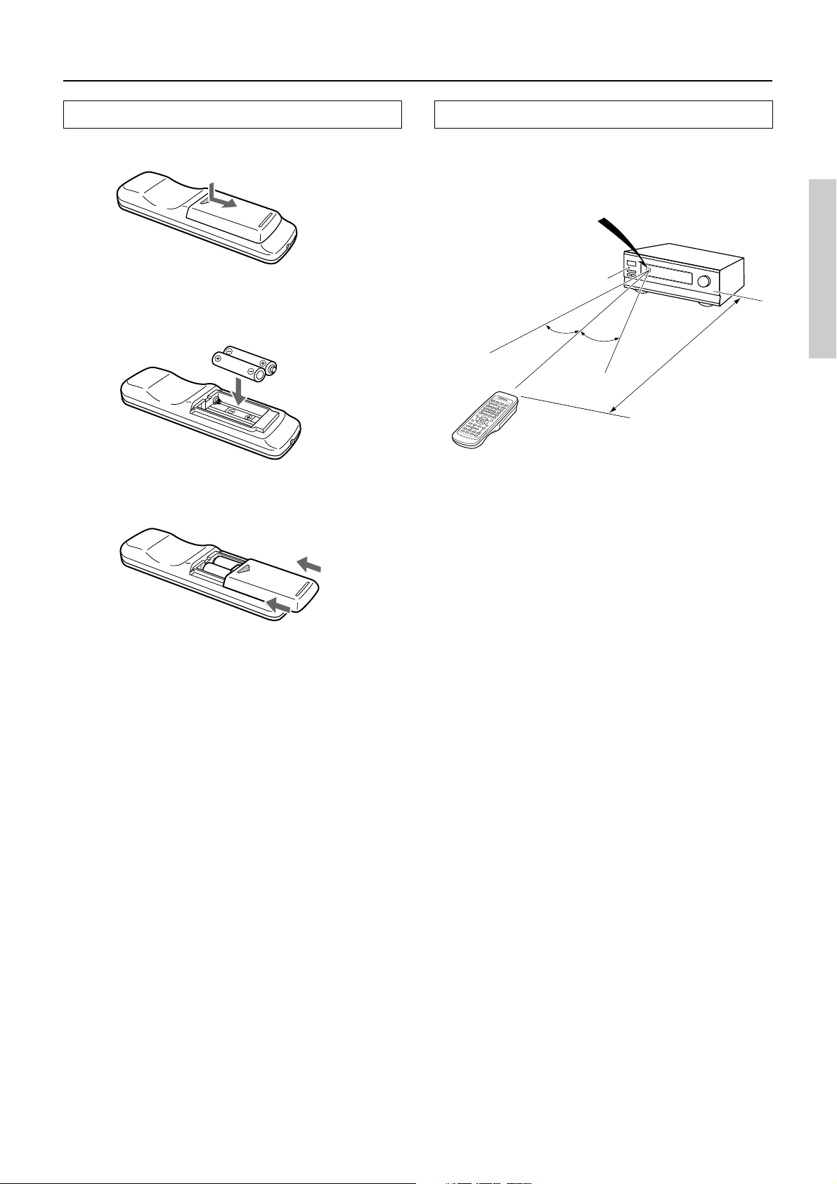
Installing batteries into the remote controller
1. Remove the battery compartment cover by
pressing and sliding the cover.
2. Insert two AA (R6 or UM-3) batteries into the
battery compartment. Carefully follow the
polarity diagram (positive (+) and negative (–)
symbols) inside the battery compartment.
3. After batteries are installed and seated correctly,
replace the compartment cover.
Notes:
• Do not mix new batteries with old batteries or different kinds
of batteries.
• To avoid corrosion, remove the batteries if the remote
controller is not to be used for a long time.
• Remove dead batteries immediately to avoid damage from
corrosion. If the remote controller does not operate smoothly,
replace both batteries at the same time.
• The life of the batteries supplied is about six months but this
will vary depending on usage.
Using the remote controller
Point the remote controller toward the remote control sensor. The
STANDBY indicator lights up when the unit receives a signal
from the remote controller.
Remote control sensor
HT-R490
STANDBY indicator
30°
Notes:
• Place the unit away from strong light such as direct sunlight or
inverted fluorescent light which can prevent proper operation
of the remote controller.
• Using another remote controller of the same type in the same
room or using the unit near equipment which uses infrared rays
may cause operational interference.
• Do not put objects on the remote controller. Its buttons may be
pressed by mistake and drain the batteries.
• Make sure the audio rack doors do not have colored glass.
Placing the unit behind such doors may prevent proper remote
controller operation.
• If there is any obstacle between the remote controller and the
remote control sensor, the remote controller will not operate.
30°
Approx. 5 meters
(16 feet)
5
Page 6
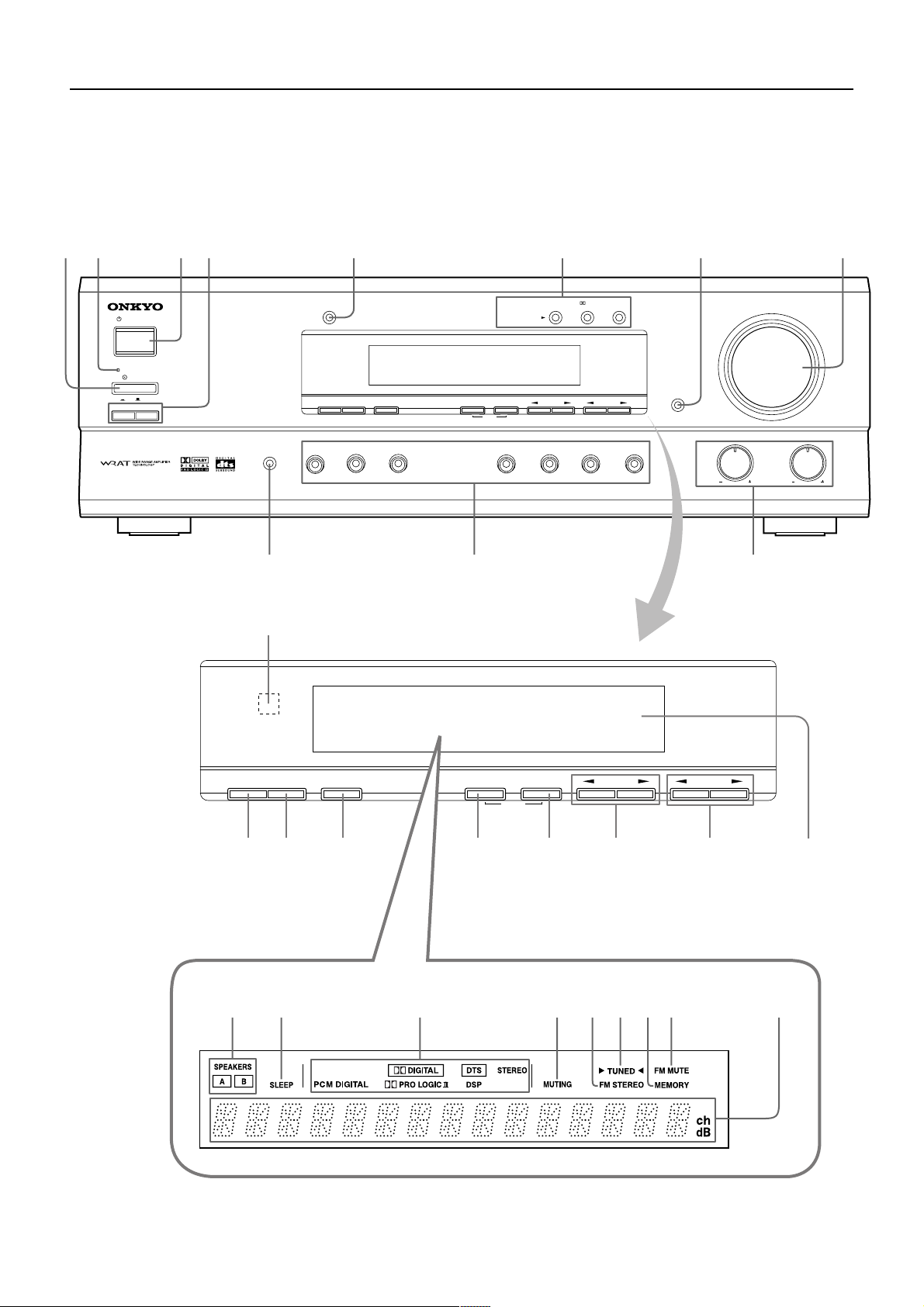
Front panel facilities
Here is an explanation of the controls and displays on the front panel of the HT-R490.
12 34 5 6 7 8
STANDBY/ON
STANDBY
POWER
ON
ABSPEAKERS
DISPLAY
OFF
AUDIO
SELECTOR
SP SEL TUNING PRESET
DVD
SW MODE
VIDEO
1
DIGITAL
INPUT
VIDEO
VCR
2
LISTENING MODE
MEMORY
MODE
FM
CLEAR
FM
STEREO
AM
DTS/
SURROUND
TAPE
DSP
DIMMER
C
D
BASS
MASTER VOLUME
TREBLE
AV RECEIVER
HT-R490
-09
=
DIGITAL
SP SEL TUNING PRESET
SW MODE
~
!@ # $ % ^ &
INPUT
MODE
MEMORY
CLEAR
FM
AB C DEFGHI
6
Page 7
Front panel facilities
1 POWER switch
Turns on the main power supply for the HT-R490. The
HT-R490 enters standby state and the STANDBY indicator lights
up. Pressing the switch again to the off position (— OFF) shuts
down the main power supply into the HT-R490.
• Before turning on the power, make sure all cables are properly
connected.
• Turning on the HT-R490 may cause a momentary power surge
that might interfere with other electrical equipment on the
same circuit. If this is a problem, plug the HT-R490 into a
different electrical circuit.
2 STANDBY indicator
Lights when the HT-R490 is in the standby state and flashes when
a signal is received from the remote controller.
3 STANDBY/ON button
When STANDBY/ON button is pressed to ON while the POWER
switch is set to ON, the display will light to show the current
volume setting for about 5 seconds then show the current sound
input source and listening mode. Pressing the button again returns
the HT-R490 to the standby state. This state turns off the display,
disables control functions.
5 DISPLAY button
Each time you press the DISPLAY button, the screen changes as
follows:
When an input source other than FM or AM is
selected:
Press the DISPLAY button once to initiate the program format
display. Pressing the button again switches the display to the other
display.
Input source +
volume
Program format*
Input source +
Listening mode
* If the input signal does not have a program format, then this
will be skipped. The format display returns to the previous
display after the format display has lasted for about 5 seconds
(
).
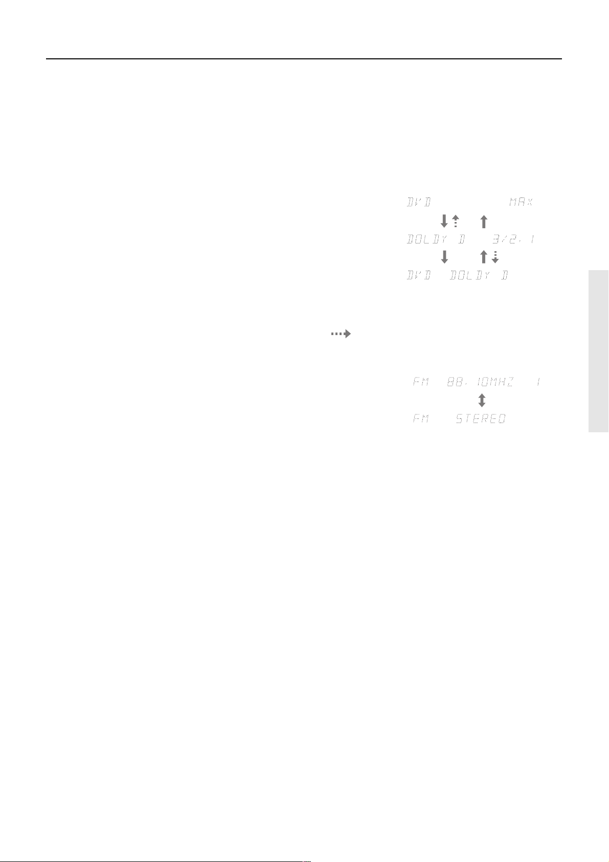
When FM or AM is selected as the input source:
4 SPEAKERS A/B buttons
Press to switch the speaker systems in use between A and B.
SPEAKERS A:
SPEAKERS A, CENTER SPEAKER, SURROUND SPEAKERS
and SUB WOOFER PRE OUT terminals. When the speakers are
turned on, the SPEAKERS A indicator lights up.
SPEAKERS B: Select for the speakers connected to the FRONT
SPEAKERS B terminals. When the speakers are turned on, the
SPEAKERS B indicator lights up.
Notes:
• Be sure to use SPEAKERS A to listen to the sound through
MULTI CHANNEL INPUT port or in any listening mode
other than STEREO.
• You cannot select surround mode when you are using
SPEAKERS B. If you select SPEAKERS B while surround
mode is selected, surround mode will be automatically
canceled.
• You cannot use the A and B speakers simultaneously.
Select for the speakers connected to the FRONT
FM/AM frequency
+ Preset no.
FM/AM +
Listening mode
ch
6 LISTENING MODE buttons
Press these buttons to select a listening mode for the current input source.
STEREO: Select for normal stereo output.
j/DTS SURROUND: Select for the DOLBY PRO LOGIC II,
DOLBY DIGITAL, or DTS surround modes.
DSP: Select for the ORCHESTRA, UNPLUGGED, or ALL CH
ST surround modes. During Dolby Digital playback, this
button is used to switch the Late Night function between ON
and OFF.
7 DIMMER button
Press to set the brightness of the front display. The brightness
changes to normal and dim.
• The dimmer control for the front display can also be performed
by using the remote controller.
8 MASTER VOLUME dial
The MASTER VOLUME dial is used to control the volume level.
Turn the dial clockwise to increase the volume level and
counterclockwise to decrease it.
9 AUDIO SELECTOR button
Press to select an audio input signal format other than FM and AM.
Each time this button is pressed, the setting cycles; “AUTO” →
“MULTI CH” → “ANALOG” → “AUTO” (back to the beginning)
(refer to page 23).
7
Page 8

Front panel facilities
0
Input Selector Buttons (DVD, VIDEO 1, VIDEO 2,
FM, AM, TAPE and CD)
These buttons are used to select the input source. Pressing and
holding the TAPE button for about 2 seconds allows the TAPE and
MD sources to be switched.
- BASS and TREBLE control knobs
Boosts or cuts the bass and treble response.
BASS: Adjusts the bass response from the Front speakers. Turn
the knob clockwise to boost the bass response. Turn the knob
counterclockwise to cut the bass response.
TREBLE: Adjusts the treble response from the Front speakers.
Turn the knob clockwise to boost the treble response. Turn the
knob counterclockwise to cut the treble response.
& Display
ASPEAKERS A/B indicators
Shows the current speaker system in use.
BSLEEP indicator
Lights up when the sleep timer is active.
CSource/Listening mode indicators
One of these indicators lights to show the format of the current
source as “PCM DIGITAL”, “Ÿ DIGITAL” or “DTS”. In
addition, one of the listening mode indicators “Ÿ PRO
LOGIC II”, “DSP” and “STEREO” lights according to the
current listening mode.
= Remote control sensor
This sensor receives the control signals from the remote controller.
~ SP SEL button
Press to select the optimum speaker configuration.
! SW MODE button
Press to select the subwoofer mode.
@ DIGITAL INPUT button
When digital components are connected to the DIGITAL INPUT
jacks of the HT-R490, use this button to assign the DIGITAL
INPUT jacks to them according to their forms of connection.
# FM MODE button
Press to switch the reception mode between stereo and monaural.
If audio is interrupted or noise interferes with audio during FM
stereo broadcasting, press this button to switch to the monaural
reception mode.
$ MEMORY button
This button is used to assign the radio station that is currently
tuned in to a preset channel or delete a previously preset station.
DMUTING indicator
Flashes when the mute function is active.
EFM STEREO indicator
Lights up when an FM stereo broadcast station is received.
FTUNED indicator
Lights up when a radio station is received.
GMEMORY indicator
Lights up when the MEMORY button is pressed in the radio
station preset operation.
HFM MUTE indicator
Lights up to indicate FM muting. It extinguishes when the
monaural reception mode is started by pressing the FM MODE
button.
IMulti function display
In usual operation, shows the current input source and volume.
When the FM or AM input is selected, it shows the frequency
and preset number. When the DISPLAY button is pressed, it
shows the listening mode and input source format. However, it
does not show the source format when the FM or AM source is
selected.
% TUNING ™/£ buttons
Use these buttons to change the tuner frequency. The tuner
frequency is displayed in the front display and it can be changed in
50 kHz increments for FM and 10 kHz increments for AM.
When FM is selected, you can hold down one of the TUNING ™/£
buttons and then release it to activate the auto-search feature. It will
search for a station in the direction of the button you pressed and stop
when it tunes into one.
^ PRESET ™/£ buttons
These buttons make it possible to store desired radio stations under
the desired preset numbers and recall them with an easy operation.
8
Page 9
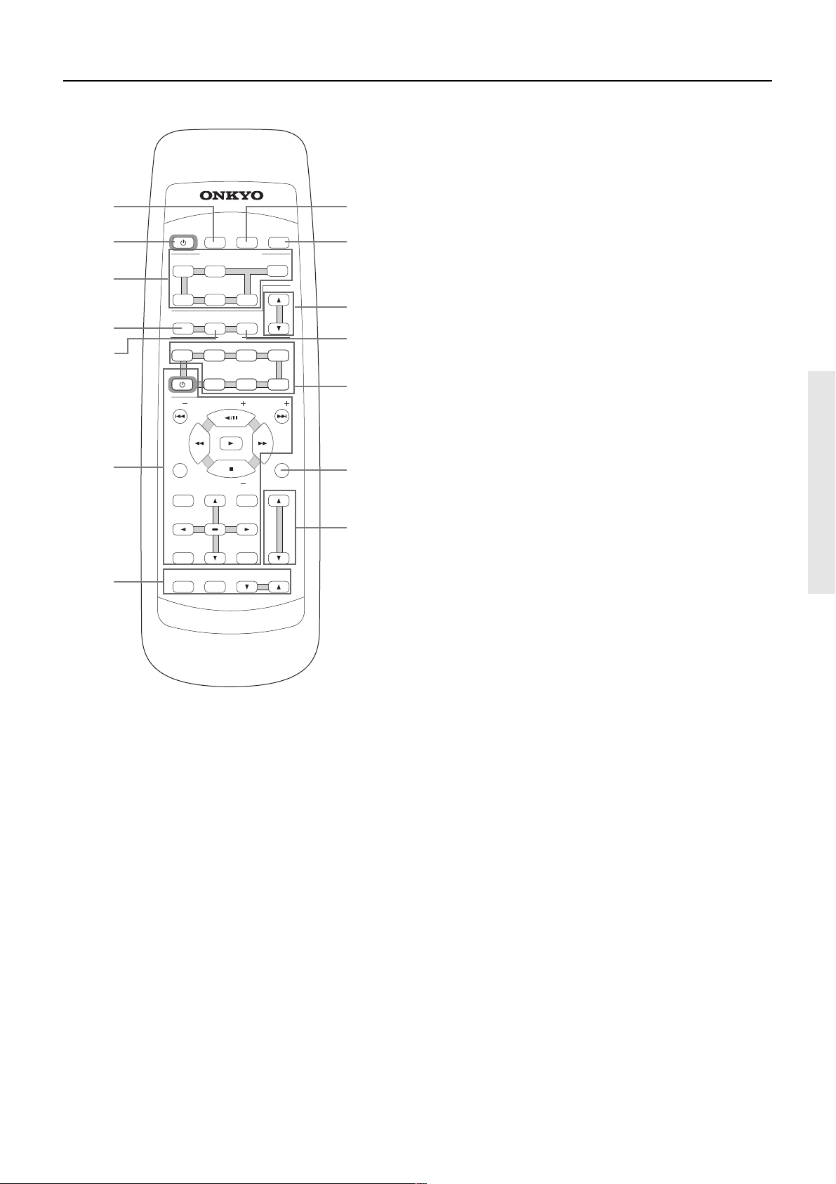
Remote controller
1
SLEEP DIMMER DISPLAY
STANDBY/ ON
2
3
4
5
INPUT SELECTOR
CD TAPE TUNER
D V D VIDEO 1 VIDEO 2
SUR MODE
SW MODE AUDIO SEL
MODE
TV CABLE SATELLI TE
STANDBY/ ON
DVD CD TAPE
CH T V VOL
TUNER
PRESET
VCR
CH
8
9
0
-
=
For detailed descriptions on the buttons, see “Front panel facilities”
on pages 6 through 8.
1 SLEEP button
For setting the sleep time.
This button is provided only on the remote controller (refer to page
23).
2 STANDBY/ON button
Turns on the HT-R490 or put it in standby.
3 INPUT SELECTOR buttons
For selecting the input source.
4 SUR MODE button
Press to select the surround mode.
5 SW MODE button
Press to select the subwoofer mode.
6
7
DISC
TV/VCR
TOP MENU
RETURN
TEST TONE
R
TV VOL
ENTER
CH SEL
E
M
O
T
E
C
-
R
C
RC-446M
O
4
4
MENU
SETUP
T
N
M
6
R
LEVEL
L
O
VOLUME
R
E
L
MUTING
~
!
6 DVD/CD/TAPE operation buttons
For operating z-connected Onkyo components connected to the
HT-R490.
You can operate TV, VCR, satellite tuner and cable TV tuner from
other brand than Onkyo by storing the pre-programming code.
For detailed descriptions on the buttons, see “Using remote
controller” on page 30 and “Pre-programming RC-446M remote
controller” on page 32.
7 TEST TONE/CH SEL/LEVEL 5/∞ buttons
For setting the output levels for each speaker.
These buttons are provided only on the remote controller (refer to
page 21).
8 DIMMER button
For adjusting the brightness of the front display.
9 DISPLAY button
For changing the display.
0 TUNER PRESET 5/∞ button
For selecting a tuner preset channel.
- AUDIO SEL button
Press to select an audio input signal format other than FM and AM.
= MODE buttons
For selecting the component to be operated by the remote
controller.
~ MUTING button
Activates the mute function.
This button is provided only on the remote controller (refer to page
23).
! VOLUME 5/∞ button
For adjusting the volume.
9
Page 10
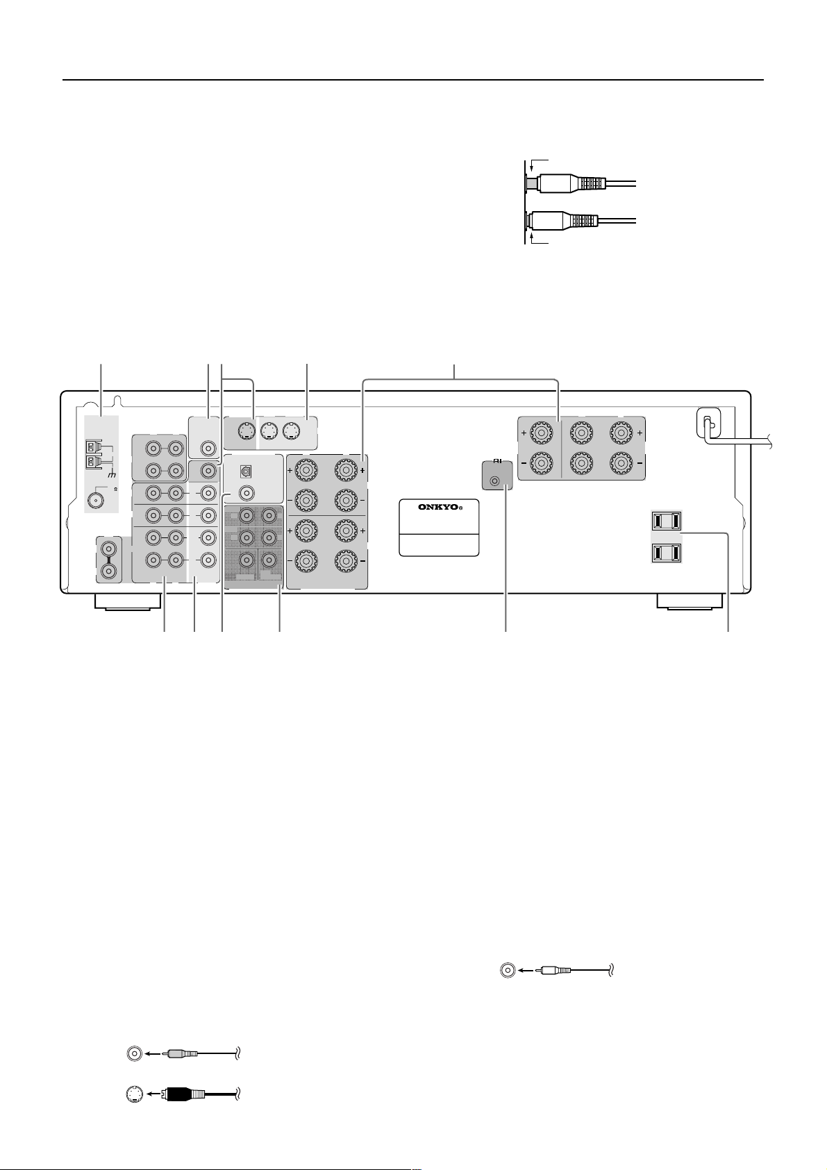
Rear panel facilities
Here is an explanation of the terminals found on the rear of the
HT-R490 and how they are used. Before connecting your audio
and video components, be sure to read this section carefully and
• Insert all plugs and connectors securely. Improper
connections can result in noise, poor performance, or
damage to the equipment.
then proceed to the explanations on how to connect each
individual component (refer to page 12).
• Be sure to always refer to the instructions that came with
the component that you are connecting.
• Do not plug in the power cord until all connections have
been made.
• For input jacks, red connectors (marked R) are used for
the right channel, white connectors (marked L) are used
for the left channel, and yellow connectors (marked
VIDEO) are used for video connections.
• Do not bind audio/video connection cables with power
cords and speaker cables. Doing so may adversely effect
the picture and sound quality.
1234 5
MONITOR
ANTENNA
L
R
SUB
WOOFER
PRE OUT
R
L
OUT
AM
TAPE
IN
FM
75
DVD
VIDEO 1
CD
VIDEO 2
MONITOR
OUT
IN
IN
OUT
IN
R
VIDEO
L
OUT
DIGITAL INPUT
FRONT
R
SURR
R
CENTER
MULTI
CHANNEL INPUT
DVD
IN
OPTICAL
COAXIAL
SUB
WOOFER
VIDEO
1
S VIDEO
IN
R
L
L
RL
FRONT SPEAKERS
L
A
AV RECEIVER
MODEL NO.
HT-R490
B
REMOTE
CONTROL
CENTER
SPEAKER
Improper connection
Inserted completely
R
L
SURROUND
SPEAKERS
AC OUTLETS
AC 120V 60Hz
SWITCHED
TOTAL 120
W 1A MAX.
678 9 p
4
1 ANTENNA
These terminals are for connecting the FM antenna and AM
antenna (refer to page 18).
2 SUB WOOFER PRE OUT
This terminal is for connecting an active subwoofer.
3 MONITOR OUT
The monitor output includes both RCA type and S video
configurations. This output is for connecting television monitors
or projectors.
4 VIDEO IN/OUT
There are 3 video inputs (RCA type and S video configurations)
and 1 RCA type video output. Connect DVD players, LD players,
VCRs or other video components to the video inputs.
The video output channel can be used to be connected to video
tape recorder for making recordings.
RCA type jack
5 SPEAKERS
Speaker terminals are provided for the front left, front right,
center, surround left and surround right speakers. Speaker outputs
are compatible with banana plug connectors.
6 AUDIO IN/OUT
These are the analog audio inputs and outputs. There are 5 audio
inputs (3 of which are linked to video inputs) and 2 audio outputs
(1 of which are linked to a video output). The audio jacks are
nominally labeled for compact disc players, cassette tape decks,
and DVD players. To the audio jacks for VIDEO 1 and 2 connect
the audio output from LD players, VCRs or other video
components. The audio inputs and outputs require RCA type
connectors.
RCA type
• When connecting a DVD, VCR or other video component,
make sure you connect the audio and video leads together (i.e.,
both to VIDEO 1).
10
S Video jack
Page 11
Rear panel facilities
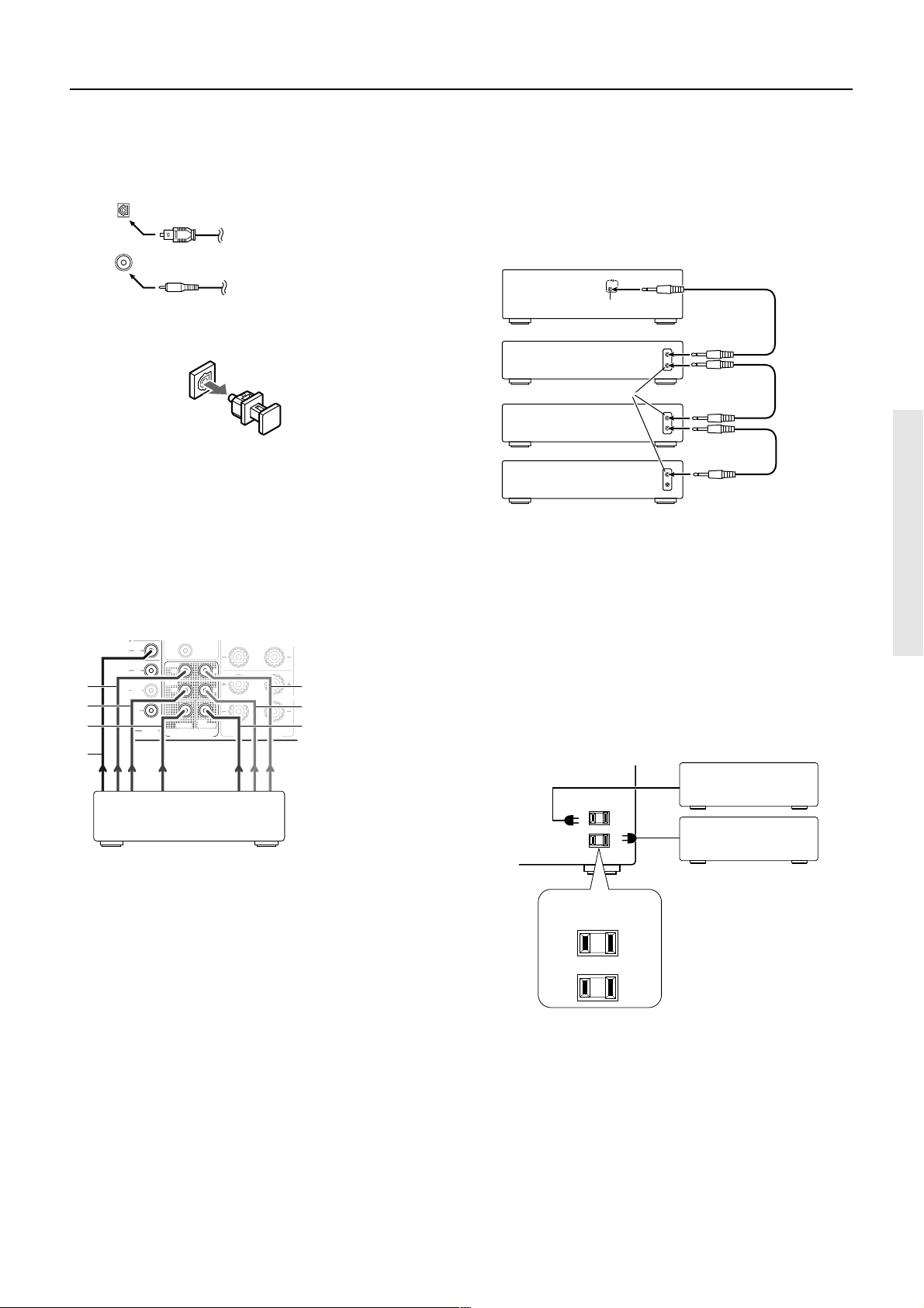
7 DIGITAL INPUT (OPTICAL/COAXIAL)
There are 2 digital inputs, one with a coaxial jack and the other
with an optical jack. The inputs accept digital audio signals from a
compact disc, LD, DVD, or other digital source component.
OPTICAL
Optical fiber cable
COAXIAL
Coaxial cable (RCA type)
• When using the optical input jack, remove the protective cap
and keep it safely. When the jack is not used, replace the
protective cap.
• When using an optical input jack, always use an optical fiber
cable.
• When using the digital inputs, make sure to also connect the
analog connections whenever possible.
8 MULTI CHANNEL INPUT
By connecting a DVD player, MPEG decoder, or other component
that has a multi channel port, you can playback the audio with 5.1
channel output. So, be sure to prepare a cable that can properly
connect the HT-R490 to the peripheral device.
IN
IN
1
2
3
OUT
IN
VIDEO
FRONT
R
SURR
R
CENTER
MULTI
CHANNEL INPUT
COAXIAL
SUB
WOOFER
7
DVD player/MPEG decoder
L
L
RL
FRONT SPEAKERS
A
4
B
5
6
1. Front right
2. Surround right
3. Center
4. Front left
5. Surround left
6. Subwoofer
7. Video
9 z (REMOTE CONTROL)
Connect the Onkyo components that have z connectors such as a
CD player, and cassette tape deck using the z cables provided
with them. When these components are interconnected, they can be
controlled from the remote controller provided with the HT-R490.
After connecting the z connectors, check the operation of the
remote controller buttons for use in controlling other components
(refer to page 30).
REMOTE
CONTROL
HT-R490
z connector
Ex: Onkyo DVD Player
z connector
Ex: Onkyo CD player
Ex: Onkyo cassette
tape deck
• For remote control operation, the audio connection cables
must also be connected.
• If the connected component has two z connectors, you can
use either one to connect to the HT-R490. The other one can be
used to daisy chain with another component.
p AC OUTLETS
The HT-R490 is supplied with AC mains outlets for connecting
the power cords from other devices so that their power is supplied
through the HT-R490. By doing this, you can use the STANDBY/
ON button on the HT-R490 to turn on and off the connected
devices as well.
Other components
• Connect the video output to one of VIDEO IN connectors
(DVD, VIDEO 1 and VIDEO 2).
AC OUTLETS
AC 120V 60Hz
SWITCHED
TOTAL 120W 1A MAX.
Caution:
Make sure that the total capacity of the other components
connected to this unit does not exceed the capacity that is printed
on the rear panel (120 watts).
11
Page 12

Example of how to connect your equipment
Here is explanation of how to connect the main components to the
HT-R490 in the standard manner. There are many ways that any
one component can be connected, and it is up to you to decide
which method best fits your situation. The directions given here
are only one option and should only be thought of as such. It is best
to fully understand the nature of each connector and terminal as
well as each of your components and their features to ascertain
which method of connection is best.
• Be sure to always refer to the instruction manual that came
with the component that you are connecting.
• Do not plug in the power cord until all connections have been
made.
• For input jacks, red connectors (marked R) are used for the
right channel, white connectors (marked L) are used for the
left channel, and yellow connectors (marked VIDEO) are used
for video connection.
• Insert all plugs and connectors securely. Improper connections
can result in noise, poor performance, or damage to the
equipment.
Improper connection
Inserted completely
• Do not bind audio connection cables with power cords and
speaker cables. Doing so may adversely effect the sound
quality.
For a detailed explanation of how to connect the devices given
below, refer to the pages listed.
Speakers: See page 17
Radio antenna: See page 18
Setting the digital inputs
When connecting digital source components to the DIGITAL
INPUT jacks on the rear panel, assign the input source button on
the front panel to either a DIGITAL INPUT OPTICAL or
COAXIAL jack depending on the type of connector on the digital
source components. The DVD, CD, VIDEO 1, VIDEO 2 and
TAPE inputs can be assigned to the DIGITAL INPUT jacks.
With the initial setting, the OPTICAL jack is assigned to the CD
input, COAXIAL jack is assigned to the DVD input, and no input
connector is assigned to the VIDEO 1, VIDEO 2 and TAPE inputs.
For example, follow the steps below to assign OPTICAL to the
DVD device connected to the DIGITAL INPUT OPTICAL jack.
1. Press the DVD Input Selector button.
The DVD input is selected and “DVD” appears in the display.
2. Press the DIGITAL INPUT button.
The current DVD setting (COAX) appears.
3. Press the DIGITAL INPUT button repeatedly to
select “OPT”.
Pressing the DIGITAL INPUT button repeatedly will change
the setting as follows:
Select if connected to DIGITAL INPUT
OPTICAL.
Select if connected to DIGITAL INPUT
COAXIAL.
Select if the input source is not from a
digital input jack.
About five seconds after “OPT” is selected, the original
display appears and the setting is completed.
If you have selected digital input, you can also select the input
signal format (refer to “Setting the input signal format” on
page 23).
Note:
Do not assign a single DIGITAL INPUT jack to more than one
source.
For example, if you assign the OPTICAL jack to the DVD input,
since the OPTICAL jack is assigned to the CD input by the initial
setting, it would result in assigning a single OPTICAL jack to both
the CD and DVD inputs.
Whenever you assign a DIGITAL INPUT jack to a different
source from the initial setting, be sure to change the initial setting
for the jack in advance.
Default setting
Input source Digital input
CD OPTICAL
AM
FM
TAPE – – – – –
VIDEO 2 – – – – –
VIDEO 1 – – – – –
DVD COAXIAL
– – – – – :
Available for digital input but not set in initial setting.
: Not available for digital input.
12
Page 13

Example of how to connect your equipment
Connecting your audio components
Connecting a CD player
Using an RCA-type audio connection cable, connect the output
terminal on the CD player to the CD L/R jacks on the HT-R490.
Make sure that you properly connect the left channel to the L jack
and the right channel to the R jack.
If the CD player has a digital output jack as well, be sure to also
connect it to either a DIGITAL INPUT OPTICAL or COAXIAL
jack on the HT-R490 depending on the type of connector on the
CD player.
With the initial settings of the HT-R490, the CD input source is set
for digital input at the OPTICAL jack. If the digital connection is
made at a different jack, this must be changed (see page 12).
Connecting a cassette tape deck, MD recorder,
DAT deck, or CD recorder
Using an RCA-type audio connection cable, connect the output
terminals (PLAY) of the device to the TAPE IN L/R jacks on the
HT-R490 and the input terminals (REC) to the TAPE OUT L/R
jacks. Make sure that you properly connect the left channel to the
L jack and the right channel to the R jack.
If the device has a digital output jack as well, be sure to also
connect it to either a DIGITAL INPUT OPTICAL or COAXIAL
jack on the HT-R490 depending on the type of connector on the
device.
With the initial settings of the HT-R490, the DIGITAL INPUT jack
for the TAPE source is not assigned. If you connect the device to
the DIGITAL INPUT jack, then this input source must be set for
digital input at the DIGITAL INPUT button (see page 12).
Example of audio equipment connections
Tape deck, MD recorder,
DAT deck, CD recorder,
(TAPE)
(REC)
RL
SUB
WOOFER
PRE OUT
MONITOR
OUT
IN
IN
OUT
IN
AUDIO OUT
(PLAY)
RL
VIDEO
ANTENNA
L
R
CD
AM
FM
75
OUT
TAPE
IN
DVD
VIDEO 1
VIDEO 2
AUDIO IN
R
L
R
L
MONITOR
OUT
DIGITAL INPUT
OPTICAL
COAXIAL
FRONT
R
SURR
R
CENTER
MULTI
CHANNEL INPUT
DVD
IN
SUB
WOOFER
L
L
Audio (L)
Audio (R)
Optical plug
Analog signal
Digital signal
Signal flow
RL
AUDIO
OUT
CD player
OPTICAL
DIGITAL
OUT
(CD)
13
Page 14

Example of how to connect your equipment
Connecting your video components
Connecting a DVD player or LD player
Using an RCA-type video connection cable, connect the video
output terminal (composite) on the device to the DVD IN VIDEO
jack on the HT-R490.
If there is an S video output terminal on the DVD player or LD player,
connect it to the DVD IN S VIDEO jack using an S video cable.
Using an RCA-type audio connection cable, connect the audio
output terminal on the DVD player or LD player to the audio DVD
IN L/R jacks on the HT-R490. Make sure that you properly
connect the left channel to the L jack and the right channel to the R
jack.
If the DVD player or LD player has a digital output jack as well, be
sure to also connect it to either a DIGITAL INPUT OPTICAL or
COAXIAL jack on the HT-R490 depending on the type of
connector on the DVD player or LD player.
With the initial settings of the HT-R490, the DVD input source is
set for digital input at the COAXIAL jack. If the digital connection
is made at a different jack, this must be changed (see page 12).
Connecting a video cassette recorder
Using an RCA-type video connection cable, connect the video
output terminal (composite) on the video cassette recorder to the
VIDEO 2 IN VIDEO jack on the HT-R490 and video input
terminal to the VIDEO 2 OUT VIDEO jack.
Using an RCA-type audio connection cable, connect the audio
output terminal on the video cassette recorder to the same VIDEO
2 IN L/R jacks on the HT-R490 and audio input terminal to the
VIDEO 2 OUT L/R jacks. Make sure that you properly connect the
left channel to the L jack and the right channel to the R jack.
If the video cassette recorder has a digital output jack as well, be
sure to also connect it to either a DIGITAL INPUT OPTICAL or
COAXIAL jack on the HT-R490 depending on the type of
connector on the video cassette recorder.
With the initial settings of the HT-R490, the DIGITAL INPUT
jack for the VIDEO 2 source is not assigned. If you connect the
video cassette recorder to the DIGITAL INPUT jack, then this
input source must be set for digital input at the DIGITAL INPUT
button (see page 12).
Connecting a satellite tuner or television
Using an RCA-type video connection cable, connect the video
output terminal (composite) on the satellite tuner or television to
the VIDEO 1 IN VIDEO jacks on the HT-R490.
If there is an S video output terminal on the satellite tuner or
television, connect it to the VIDEO 1 IN S VIDEO jack using an S
video cable.
Using an RCA-type audio connection cable, connect the audio
output terminal on the satellite tuner or television to the same
VIDEO 1 IN L/R jacks on the HT-R490. Make sure that you
properly connect the left channel to the L jack and the right
channel to the R jack.
If the satellite tuner or television has a digital output jack as well,
be sure to also connect it to either a DIGITAL INPUT OPTICAL
or COAXIAL jack on the HT-R490 depending on the type of
connector on the satellite tuner or television.
With the initial settings of the HT-R490, the DIGITAL INPUT
jack for the VIDEO 1 source is not assigned. If you connect the
video cassette recorder to the DIGITAL INPUT jack, then this
input source must be set for digital input at the DIGITAL INPUT
button (see page 12).
Connecting a television monitor or projector
Using an RCA-type video connection cable, connect the video
input terminal (composite) on the monitor to the MONITOR OUT
VIDEO jack on the HT-R490.
If there is an S video input terminal on the monitor, connect it to
the MONITOR OUT S VIDEO jack using an S video cable.
14
Page 15

Example of how to connect your equipment
Example of video equipment connections
DVD player or LD player
(DVD)
AUDIO
OUT
ANTENNA
LR
VIDEO
OUT
L
R
CD
DIGITAL
COAXIAL
AM
FM
75
OUT
TAPE
DVD
VIDEO 1
VIDEO 2
S VIDEO
OUT
OUT
IN
TV monitor or Projector
(MONITOR OUT)
S VIDEO
VIDEO
IN
IN
SUB
WOOFER
R
R
PRE OUT
L
MONITOR
OUT
IN
IN
OUT
IN
VIDEO
L
MONITOR
OUT
DIGITAL INPUT
FRONT
R
SURR
R
MULTI
CHANNEL INPUT
CENTER
DVD
IN
OPTICAL
COAXIAL
SUB
WOOFER
1
VIDEO
S VIDEO
IN
R
L
L
RL
FRONT SPEAKERS
L
A
B
S VIDEO
OUT
AUDIO
OUT
VIDEO
OUT
Satellite tuner or TV
(VIDEO 1)
RL RLLR
AUDIO
OUT
VIDEO
OUT
VCR
(VIDEO 2)
AUDIO
IN
VIDEO
IN
Video
Audio (L)
Analog signal
Audio (R)
S Video plug
S video signal
Coaxial plug
Digital signal
Signal flow
15
Page 16

Positioning speakers
This unit has two sets of speaker system terminals (for
SPEAKERS A and SPEAKERS B).
Before connecting the speakers, place them correctly by
consulting the instruction manuals that came with them.
For surround playback, the configuration and placement of your
speakers are very important.
Standard speaker system for reproducing
surround sound
• Front right and left speakers
• Center speaker
Produces a rich sound image by serving as a sound source for
the front right and left speakers and enhancing the sonic
movement.
• Surround right and left speakers
Adds three-dimensional sonic movement and produces
environmental sound associated with the background and
effect sound for each scene.
• Subwoofer
Produces powerful and heavy bass.
Speaker placement
Ideal speaker placement varies depending on the size of your room
and the wall coverings. Here, only typical example of speaker
placement and recommendations are shown.
Important points regarding speaker placement
Front left and right speakers and center speaker
• Place these three speakers at the same height from the floor.
• Place each speaker so that sound is aimed at the location of the
listener’s ears at the listening position.
• Install the left and right front speakers at the same distance
from the listening position.
Surround left and right speakers
• Place these speakers so that their height is 1 meter (3.3 feet)
higher than that of the listener’s ears.
Subwoofer
• The subwoofer can provide a similar sound effect regardless of
the installation position, provided that it is installed within the
room containing the listening position.
If the subwoofer and center speaker are not
available
The sound recorded for the center speaker and the subwoofer will
be properly distributed to the front right and left speakers for
optimized surround playback.
Front left
speaker
Surround
left
speaker
Subwoofer
TV/Monitor screen
Center
Speaker
Listening position
Front right
speaker
Surround
right
speaker
16
Page 17

Connecting speakers
R
L
Connecting speakers
After installing the speakers, connect them to the HT-R490.
CAUTION:
SPEAKER IMPEDANCE
6 Ω min. per each speaker terminal.
Preparation of speaker cords
1.
Strip away 15 mm (5/8 inch)
15mm (5/8")
of wire insulation.
2. Twist wire ends very tight.
Connecting the speaker cord
1. Loosen the screw.
2. Fully insert the end of the
cord.
• To prevent damage to circuitry, never short-circuit the positive
(+) and negative (–) speaker wire.
NO!
• Be sure to connect the positive and negative cables for the
speakers properly. If they are mixed up, the left and right
signals will be reversed and the audio will sound unnatural.
• Connect speakers with an impedance between 6 Ω and 16 Ω.
Connecting speakers with an impedance less that 6 Ω may
damage the HT-R490.
• Do not connect more than one speaker cable to one speaker
terminal. Doing so may damage the HT-R490.
• When you are using only one speaker or when you wish to
listen to monaural (mono) sound, a single speaker should
never be connected in parallel to both the right and leftchannel terminals simultaneously.
NO!
NO!
L
R
3. Tighten the screw.
Connecting to SPEAKERS A
Subwoofer
MONITOR
ANTENNA
L
R
R
OUT
AM
TAPE
IN
FM
75
DVD
VIDEO 1
CD
VIDEO 2
R
SUB
OUT
WOOFER
PRE OUT
L
MONITOR
OUT
IN
FRONT
IN
SURR
OUT
IN
VIDEO
L
Front right
speaker
DVD
DIGITAL INPUT
OPTICAL
COAXIAL
R
R
SUB
CENTER
WOOFER
MULTI
CHANNEL INPUT
VIDEO
IN
IN
L
L
Front left
speaker
1
S VIDEO
L
R
A
B
RL
FRONT SPEAKERS
Connecting a subwoofer
Use the SUB WOOFER PRE OUT jack to connect a subwoofer
with a built-in power amplifier.
If your subwoofer does not have a built-in amplifier, connect an
amplifier to the SUB WOOFER PRE OUT jack and the subwoofer
to the amplifier.
R
Surround
left
speaker
L
SURROUND
SPEAKERS
TOTAL 120
AC OUTLETS
AC 120V 60Hz
SWITCHED
W 1A MAX.
AV RECEIVER
MODEL NO.
HT-R490
Center
speaker
CENTER
SPEAKER
REMOTE
CONTROL
Surround
right
speaker
Connecting to SPEAKERS B
Front right
speaker
Front left
speaker
17
Page 18

Connecting antennas
To the use the tuner of HT-R490, it is necessary to prepare the
supplied FM and AM antennas.
• Adjustment and placement of the FM and AM antennas for
better reception must be done while listening to a station
broadcast.
• If better reception cannot be obtained, then placement of an
outside antenna is recommended.
Connecting the FM indoor antenna
1. Strip away the insulation from the end of the
cord.
FM indoor antenna
2. Fully insert the stripped end of the cord.
ANTENNA
R
OUT
AM
TAPE
IN
FM
75
DVD
The FM indoor antenna is for indoor use only. During use, extend
the antenna and move it in various directions until the clearest
signal is received. Fix it with push pins or similar implements in
the position that will cause the least amount of distortion.
If the reception is not very clear with the attached FM indoor
antenna, the use of an outdoor antenna is recommended.
SUB
WOOFER
PRE OUT
L
MONITOR
OUT
IN
Assembling the AM loop antenna
1. Rotate the outer frame of
the antenna.
Connecting the AM loop antenna
1. Press down the lever.
2. Insert the end of the
cable into the hole.
3. Release the lever.
The lever will return to the
original position.
AM loop antenna
ANTENNA
R
OUT
AM
TAPE
IN
FM
75
DVD
Either of the split ends of the AM antenna can be connected to
either terminal. Unlike speaker cabling, there is no polarity for
AM broadcast signals.
The AM loop antenna is for indoor use only. Set it in the direction
and position where you receive signals clearly. Put it as far away
as possible from the HT-R490, televisions, speaker cables, and
power cords.
When reception is not satisfactory with the attached AM loop
antenna alone, connection of an outdoor antenna is recommended.
SUB
WOOFER
PRE OUT
L
MONITOR
OUT
IN
2. Insert the bottom edge of
the outer frame into the
groove on the stand.
3. Extend the antenna cord.
18
Insert into the groove.
Page 19

Connecting antennas
If the reception condition cannot be improved by adjusting the
provided antenna, install an outdoor antenna and connect it to this unit.
Connecting an FM outdoor antenna
Please make sure that you follow the considerations:
• Keep the antenna away from noise sources (neon signs, busy
roads, etc.).
• It is dangerous to put the antenna close to power lines. Keep it
well away from power lines, transformers, etc.
• To avoid the risk of lightning and electrical shock, grounding
is necessary. Follow item 14 of the “Important Safeguards” on
page 2 when you install the outdoor antenna.
FM outdoor
antenna
ANTENNA
AM
TAPE
FM
75
DVD
VIDEO 1
SUB
WOOFER
PRE OUT
R
L
OUT
MONITOR
IN
OUT
IN
IN
Connecting an AM outdoor antenna
An outdoor antenna will be more effective if it is stretched
horizontally above a window or outside.
AM loop antenna (Indoor)
Outdoor antenna
Connect both
antennas.
ANTENNA
R
L
OUT
AM
TAPE
IN
Notes:
• Do not remove the AM loop antenna.
• To avoid the risk of lightning and electrical shock, grounding
is necessary. Follow item 14 of the “Important Safeguards” on
page 2 when you install the outdoor antenna.
Directional linkage
Do not use the same antenna for both FM and TV (or VCR)
reception since the FM and TV (or VCR) signals can interfere with
each other. If you must use a common FM/TV (or VCR) antenna,
use a directional linkage type splitter.
To HT-R490
To TV (or VCR)
19
Page 20

Connecting the power
STANDBY/ON
OFF
ON
POWER
MASTER VOLUME
BASS
TREBLE
AV RECEIVER
HT-R490v
FM
AM C
D
TAPE
VIDEO
1
DVD
ABSPEAKERS
DIMMER
SURROUND
DTS/
VIDEO
2
VCR
AUDIO
SELECTOR
LISTENING MODE
DSP
STEREO
DISPLAY
STANDBY
SP SEL TUNING PRESET
MEMORY
SW MODE
DIGITAL
INPUT
FM
MODE
CLEAR
INPUT SELECTOR
SLEEP DIMMER DISPLAY
CD TAPE TUNER
DV D VIDEO 1 VIDEO 2
SUR MODE
SW MODE AUDIO SEL
TUNER
PRESET
STANDBY/ON
DISC
MUTING
VOLUME
TOP MENU
MENU
CH SEL
RETURN
SETUP
TEST TONE
LEVEL
ENTER
POWER
STANDBY/ON
STANDBY/ON
CH
TV/VCR
CH TV VOL
TV VOL
R
C
-
4
4
6
M
R
E
M
O
T
E
C
O
N
T
R
O
L
L
E
R
MODE
TV CABLE SAT ELLITE
VCR
STANDBY/ON
DVD CD TAPE
STANDBY indicator
To wall outlet
Connecting the power
• The HT-R490 is shipped with the main power (POWER)
switch in the on position (
_ ON
). When the power cord is
plugged in for the first time, the HT-R490 will automatically
enter the standby state and the STANDBY indicator will light
(same condition after step 2 below).
• Before you plug in the HT-R490, confirm that all connections
have been made properly.
• Turning on the power may cause a momentary power surge,
which might interfere with other electrical equipment on the
same circuit, such as computers. If this happens, use a wall
outlet on a different circuit.
1. Plug the power cord into an AC wall outlet.
2. Press the POWER switch to set the HT-R490 to
standby state.
The STANDBY indicator lights up.
3. Press the STANDBY/ON button to turn on the
HT-R490.
The display lights up and the STANDBY indicator turns off.
If you press the STANDBY/ON button again, the receiver
returns to standby mode.
Turning this unit ON from an z-connected
component
When the DVD player, CD player or MD recorder connected with
the HT-R490 through z cables is turned on, the HT-R490
automatically turns on and selects the source that was turned on.
Turning the HT-R490 off sets the z-connected DVD player, CD
player or MD recorder to standby mode.
When the HT-R490 is already on, pressing the play button on the
DVD player, CD player, cassette deck or MD recorder merely
selects the input source that was played.
Notes:
•
The function of turning on the HT-R490 is not available if its
POWER switch is set to the off position (— OFF) or the source
components is not connected properly. When controlling the
HT-R490 from an z-connected component, make sure that
the POWER switch of this unit is set to the on position (_ ON)
and that the component is connected properly.
•
When a cassette tape deck or MD recorder is connected with
the z connector of this unit, it can be controlled from the
source component selected with the TAPE button.
• Certain component models may not be able to control the
HT-R490.
Before you can use the remote controller, you must perform steps
1 and 2 above and place the HT-R490 in the standby state.
Press the STANDBY/ON button on the remote
controller to turn on the HT-R490 (take it out of the
standby state).
20
Turning the power on from the remote
controller
• To return the HT-R490 to the standby state, press the
STANDBY/ON button on the remote controller.
Memory preservation
This unit does not require memory preservation batteries. A
built-in memory power backup system preserves the contents
of the memory during power failures and even when the
POWER switch is set to off. The POWER switch must be set
to on in order to charge the backup system.
The memory preservation period after the unit has been
turned off varies depending on climate and placement of the
unit. On the average, memory contents are protected over a
period of a few weeks after the last time the unit has been
turned off. This period is shorter when the unit is exposed to a
highly humid climate.
Page 21

Speaker Setup
STANDBY/ON
STANDBY
ABSPEAKERS
SP SEL
POWER
ON
OFF
AUDIO
SELECTOR
SW MODE
DISPLAY
DIGITAL
INPUT
SP SEL TUNING PRESET
SW MODE
VIDEO
1
DVD
FM
VIDEO
2
VCR
SLEEP DIMMER DISPLAY
STANDBY/ON
INPUT SELECTOR
CD TAPE TUNER
DV D VIDEO 1 VIDEO 2
TUNER
PRESET
SUR MODE
SW MODE AUDIO SEL
MODE
VCR
DTS/
STEREO
DSP
SURROUND
LISTENING MODE
MEMORY
MODE
CLEAR
FM
AM C
TAPE
DIMMER
D
MASTER VOLUME
BASS
TREBLE
AV RECEIVER
HT-R490
SW MODE
TEST TONE
CH SEL
TV CABLE SAT ELLITE
STANDBY/ON
DVD CD TAPE
CH TV VOL
DISC
TV/VCR
TV VOL
TOP MENU
ENTER
RETURN
CH SEL
TEST TONE
R
E
M
O
T
E
R
CH
MUTING
E
VOLUME
R
VOLUME 5/∞
LEVEL 5/∞
MENU
SETUP
LEVEL
L
L
O
R
C
T
O
N
-
C
M
6
4
4
You need to set up the speaker configuration for the speaker
system connected to the SPEAKERS A terminals (see page 17).
Notes:
• The speakers cannot be set up for optimum audio reproduction
if the SPEAKERS B system is On (see page 7).
• It is not necessary to set up again once you have completed the
setup unless you change the speaker configuration.
Selecting the speaker configuration
Press SP SEL button repeatedly to select the number of
channels for the SPEAKERS A system.
When the button is pressed, the current speaker setup will be
displayed for about 5 seconds. If you want to change it, press the
same button again within the 5 seconds.
When the button is pressed repeatedly, the number of channels
changes as follows:
Front left and right speakers
Front left, right, and center speakers
Front left and right, plus surround
left and right speakers
Note:
When the subwoofer mode is set to MODE 2 and audio is
reproduced in the STEREO mode, the subwoofer may not output
audio from certain sources (2 channel-Dolby Digital/DTS source
etc.).
Adjusting each speaker’s relative volume
balance (Remote controller only)
Adjust each speaker’s relative volume balance so that the volume
of all speaker’s test tones sound equal at the listening position.
1. Press the TEST TONE button.
Adjust the volume by gently increasing it with the VOLUME
5 button. Each speaker produces the test tone (pink noise) in
the following order:
Front left speaker
Center speaker
Front right speaker
Front left, right, and center, plus
surround left and right speakers
Setting the subwoofer mode
Press SW MODE button repeatedly to select the
subwoofer mode.
When the button is pressed, the current subwoofer mode will be
displayed for about 5 seconds. If you want to change it, press the
same button again within the 5 seconds.
When the button is pressed repeatedly, the subwoofer mode
changes as follows:
When small-with limited bass signal
handling-front speakers are connected
When large-wideband-front speakers
are connected
When no subwoofer is connected
Surround right speaker
Surround left speaker
Subwoofer
2. To adjust the level of each speaker, press the
CH SEL button to select a speaker and press the
LEVEL 5/∞ buttons to raise or lower the level.
The test tone should sound at the same level when you hear it
in your listening position. You can adjust the level in the range
between –12 dB to +12 dB.
3. Press the TEST TONE button to complete
adjustment.
21
Page 22

Selecting a sound source
SPEAKERS A
STANDBY/ON
STANDBY
POWER
ON
OFF
ABSPEAKERS
SELECTOR
AUDIO SELECTOR
DISPLAY
DIGITAL
INPUT
SP SEL TUNING PRESET
SW MODE
AUDIO
VIDEO
1
DVD
VIDEO
MODE
FM
2
VCR
Input selector
LISTENING MODE
MEMORY
CLEAR
FM
DTS/
STEREO
SURROUND
AM C
TAPE
Selecting a sound source
1. Press the desired input selector button.
The selected source name appears in the display.
If the TAPE button is pressed, either the TAPE or MD input
which has been selected beforehand will be displayed. The
TAPE and MD sources can be switched alternately by holding
the TAPE button for about 2 seconds.
2. When the selected source is other than FM or
AM, press the AUDIO SELECTOR button on the
front panel or the AUDIO SEL button on the
remote controller to select an audio input signal
format.
Each time the button is pressed, the setting cycles; “AUTO”
“MULTI CH” → “ANALOG” → “AUTO” (back to the
beginning) (refer to page 23).
3. Make sure that the
SPEAKERS A indicator lights
up in the display.
If it does not light, press the SPEAKERS A button.
4. Start playing the selected input source.
Follow the operating instructions for the source device.
5. Adjust the volume with the MASTER VOLUME
dial on the front panel or the VOLUME 5/∞
buttons on the remote controller.
Turn the MASTER VOLUME dial clockwise to increase the
volume or counterclockwise to decrease it.
6. Adjust the tone with the BASS and TREBLE
control knobs on the front panel.
Turn the BASS and TREBLE control knobs to adjust the bass
and treble response from the Front speakers (refer to page 8).
Note:
If you hear no sound from the speakers, check the following items:
• Make sure that all devices and speakers are connected
correctly and securely.
• The sound is muted when the MUTING indicator flashes.
Press the MUTING button on the remote controller to cancel
the mute function (refer to page 23).
• When you select a source that is connected to the DIGITAL
INPUT jacks on the rear panel, you must select digital input
(refer to page 12).
MASTER VOLUME
DSP
DIMMER
D
BASS
BASS/TREBLE
→
MASTER VOLUME
TREBLE
AV RECEIVER
HT-R490
SLEEP
TEST TONE
CH SEL
SLEEP DIMMER DISPLAY
STANDBY/ON
INPUT SELECTOR
CD TAPE TUNER
DV D VIDEO 1 VIDEO 2
SUR MODE
SW MODE AUDIO SEL
MODE
TV CABLE SAT ELLITE
STANDBY/ON
DVD CD TAPE
CH TV VOL
DISC
TV/VCR
TV VOL
TOP MENU
MENU
ENTER
RETURN
SETUP
TEST TONE
CH SEL
R
E
M
O
T
O
E
R
C
T
O
N
-
R
C
M
6
4
4
INPUT
SELECTOR
TUNER
PRESET
VCR
AUDIO SEL
CH
MUTING
MUTING
VOLUME
VOLUME 5/∞
LEVEL
LEVEL 5/∞
R
E
L
L
Using MULTI CHANNEL INPUT
The MULTI CHANNEL INPUT refers to a system, which is
compatible with a source component equipped with 5.1-channel
outputs (DVD player, MPEG decoder, etc.), reproducing the left/
right front, center and left/right surround channels from five
respective speakers and outputting the subwoofer channel from
SUB WOOFER PRE OUT (refer to page 11).
1. Press AUDIO SELECTOR button repeatedly to
select “MULTI CH”.
2. Turn on the component connected to the MULTI
CHANNEL INPUT port and start playing the
desired media.
3. If necessary, press the CH SEL button on the
remote controller to select an individual
speaker. Then press the LEVEL 5/∞ button to
adjust the output level as desired.
Adjust the speaker output level so that you can hear the same
sound level from each speaker at the listening position. For the
front right, front left, center, surround right and surround left
speakers, the output levels can be adjusted between –12 to +12
dB. The subwoofer can be adjusted between –30 to +12 dB.
The volume levels from the speakers reproducing MULTI
CHANNEL INPUT are independent from the speaker levels
set using the test tone (page 21). These settings are not applied
to speakers reproducing MULTI CHANNEL INPUT.
Notes:
• MULTI CH cannot be selected when FM or AM is selected as
the input source.
• The surround mode cannot be selected when MULTI CH is
selected. Also, if MULTI CH is selected during use of a
surround mode, it is canceled automatically.
• If the speaker level is set to +1 dB or higher, the maximum
level indicated in the display will change if you raise the
volume level.
• Regardless of the speaker configuration, the input signal will
be output to each corresponding speaker. For example, even if
the speaker configuration is set to 2 ch, sound comes from all
speakers.
22
Page 23

Selecting a sound source
Setting the input signal format
If the input source is DVD, CD, VIDEO 1, VIDEO 2 or TAPE, you
can specify the input signal format.
With the initial setting, AUTO is assigned to the DVD and CD
inputs, and ANALOG is assigned to the TAPE, VIDEO 1 and
VIDEO 2 inputs. You can change this according to the signal
format of the input source.
For example, follow the steps below to specify the input signal
format for the VIDEO 2 input:
1. Press the VIDEO 2 button.
VIDEO 2 is selected as the input source and “VIDEO 2”
appears in the display.
2. Press the AUDIO SELECTOR button.
The current setting is displayed.
3.
Press the AUDIO SELECTOR button repeatedly
until the desired input signal format is displayed.
Each press of the button switches the displayed input format as
follows. AUTO is skipped when the selected input is not
assigned to the DIGITAL INPUT jacks (refer to page 12).
Sleep function (Remote controller only)
The sleep timer can turn off the power to the system after a
specified time period.
Press the SLEEP button on the remote controller.
The SLEEP indicator will light and “SLEEP 90 MIN” (the
HT-R490 will turn off after 90 minutes) appears in the display.
• Pressing the SLEEP button each time reduces the time value in
10-minute increments.
• To cancel the sleep function, press the SLEEP button when the
time displayed is less than 10 minutes.
• While the sleep function is enabled, you can press the SLEEP
button to see how much time is left.
Mute function (Remote controller only)
The muting function can turn down the playback sound
immediately. This can useful, for example, when you receive a
telephone call while listening to music or another source.
Select this setting to play a digital
signal. When a digital signal is not
input, the analog signal is played.
Select this setting to play back the
input from the component connected
to the MULTI CHANNEL INPUT port.
Select this setting to play back the
input from a source component
connected to an audio input jack.
After 5 seconds, the original display appears and the setting is
completed.
Notes:
• With ANALOG setting, even if a digital signal is input from
the same component, only the analog signal will be output.
• When a digital input setting is changed while an input signal
format other than MULTI CH is set, the digital input becomes
automatically ANALOG if it has been “– – – – –” or “AUTO”
if it has been “OPT” or “COAX”.
Press the MUTING button on the remote controller.
The MUTING indicator will flash and the sound from the speakers
will be switched off by the receiver’s audio muting circuits.
MUTING
Press the MUTING button again to turn the sound back on.
Note:
The mute function will be cancelled if you turn off the HT-R490.
23
Page 24

Listening to Radio Broadcasts
PRESET a/s
FM MODE
MEMORY
TUNER
TUNER
PRESET 5/∞
STANDBY/ON
OFF
ON
POWER
MASTER VOLUME
BASS
TREBLE
AV RECEIVER
HT-R490
FM
AM C
D
TAPE
VIDEO
1
DVD
ABSPEAKERS
DIMMER
SURROUND
DTS/
VIDEO 2
VCR
AUDIO
SELECTOR
LISTENING MODE
DSP
STEREO
DISPLAY
STANDBY
SP SEL TUNING PRESET
MEMORY
SW MODE
DIGITAL
INPUT
FM
MODE
CLEAR
AM
FM TUNING a/s
INPUT SELECTOR
SLEEP DIMMER DISPLAY
CD TAPE TUNER
DV D VIDEO 1 VIDEO 2
SUR MODE
SW MODE AUDIO SEL
TUNER
PRESET
STANDBY/ON
DISC
MUTING
VOLUME
TOP MENU
MENU
CH SEL
RETURN
SETUP
TEST TONE
LEVEL
ENTER
CH
TV/VCR
CH TV VOL
TV VOL
R
C
-
4
4
6
M
R
E
M
O
T
E
C
O
N
T
R
O
L
L
E
R
MODE
TV CABLE SAT ELLITE
VCR
STANDBY/ON
DVD CD TAPE
Listening to FM/AM radio stations
FM and AM broadcasting can be received either by tuning into a
station or selecting a preset station.
AM
Band
Frequency
FM
FM STEREO indicator
Band Frequency
TUNED indicator
TUNED indicator
FM MUTE indicator
Tuning into a radio station
1. Press either the AM or FM input selector button.
2. Using the TUNING a/s buttons on the front
panel, tune into the station you desire.
When you tune into a radio station, TUNED indicator appears
in the display. If you tune into an FM station in stereo, then FM
STEREO indicator lights up.
• The tuner frequency changes in 50 kHz increments for FM
and 10 kHz increments for AM.
• When tuning into FM stations, you can press the TUNING
a/s button continuously for more than 0.5 seconds to
scan for an FM station in the direction of the button you
pressed (FM auto tuning mode). After you release the
button and a station is received in stereo, the scanning
stops.
If no FM station can be tuned in automatically:
If the signal is weak or is too noisy, press the FM MODE
button to cancel the FM MUTE function. This turns the FM
MUTE indicator off and initiates the monaural reception
mode. In this mode, noise between stations is audible but
sound interruption experienced in the stereo reception mode is
removed.
To return to the stereo reception mode, press the FM MODE
button so that the FM MUTE indicator lights up.
24
Page 25

Listening to Radio Broadcasts
Presetting a radio station
By storing (presetting) frequently received radio stations, they can
be received automatically by pressing the PRESET
on the front panel or TUNER PRESET 5/∞ buttons on the remote
controller.
Up to a total of 30 FM and AM stations can be preset.
™/£
button
1. Tune into the radio station you desire.
FM STEREO
2.
Press the MEMORY button and, while the MEMORY
indicator lights, press the PRESET ™/£ button to
select the preset number (one of 1 to 30) to be used
with the station to be preset.
Lights
FM STEREO MEMORY
Flashes (Preset number)
3.
Press the MEMORY button to finalize the procedure.
Lights off
FM STEREO
Selecting a preset radio station
1. Press either the AM or FM input selector button.
The display should show the currently selected frequency. If it
displays the listening mode, press the DISPLAY button to
display the frequency.
2. Using the PRESET
™/£
buttons, select the
number of the desired preset station.
When using the remote controller
1. Press the TUNER input selector button on the
remote controller.
5/∞
2. Press the TUNER PRESET
buttons and
select the number of the desired preset station.
Erasing a preset radio station
1.
Select the preset radio station that you want erase.
Refer to “Selecting a preset radio station” above.
2. Press the FM MODE button while holding down
the MEMORY button.
FM MODE
MEMORY
CLEAR
Lights
This programs the radio station as a preset radio station.
• Once the preset station has been cancelled, the memory
location can be used to store another station.
25
Page 26

To enjoy Surround mode
The HT-R490’s surround sound enables you to enjoy the presence
of a movie theater or concert hall in your room.
Before using a surround mode, make sure the speaker setup has
been set (refer to page 21).
The configuration of the speakers are very important for the
surround sound. Refer to “Positioning speakers” on page 16 and
“Connecting speakers” on page 17.
Surround modes
DOLBY DIGITAL Surround, DTS (Digital Theater
System) Surround
This 5.1-channel digital surround format enables you to individually
record and play five full-range (20 Hz-20 kHz) channels (left and
right front, center, two surround channels) plus an LFE channel
(Low Frequency Effect) for the low-range effect sound. It will create
a realistic sound that could be heard in the theaters and concert halls.
DOLBY DIGITAL: Select this option when you play a DVD
video that has a mark.
DTS: Select this option when you play a DVD player, laser disc,
or CD that has a
mark.
DOLBY PRO LOGIC II surround
This is a 5-channel surround system of a new generation, casting a
bridge between the previous 4-channel (Left/Right Front, Center
and monaural surround channels) Pro Logic surround and 5.1channel Dolby Digital surround. Dolby Pro Logic II provides the
MOVIE mode optimized for viewing movies and the MUSIC
mode optimized for listening to music. In the MOVIE mode, the
surround channel, which has been monaural and based on narrow
band, is reproduced in stereo so that the feeling of movement in the
played movies is more enhanced. In the MUSIC mode, the
surround channel reproduces natural sound field even with 2channel music sources.
The MOVIE mode allows you to enjoy VHS and DVD software
carrying the
programs. The MUSIC mode allows you to enjoy stereo music
from CD, etc.
marking as well as some of TV broadcast
Notes on DTS
• If you play a CD or LD that supports DTS when the
“ANALOG” setting is selected on the HT-R490, the DTS
encoded signal will not be decoded and noise will be output.
This noise could damage the amplifier and speakers.
Therefore, be sure to select “AUTO” and use the DIGITAL
INPUT jacks (OPTICAL/COAXIAL) to connect the DTS
source. (Refer to “Setting the input signal format” on page 23.)
• If you play a CD or LD that supports DTS when the “AUTO”
setting is selected, you may hear a noise for a short while until
the DTS decoder recognizes the DTS encoded signal and starts
operating. This is not a malfunction.
• If you press the pause or skip button on the player while
playing a DTS source, a short noise may be heard. This is not a
malfunction.
• The DTS indicator on the HT-R490 lights up while it plays the
DTS source. When playback concludes and the DTS signal
transmission stops, the HT-R490 remains in DTS mode and
the DTS indicator remains lit. This prevents noise when you
operate the pause or skip button on the player. Therefore, if the
source switches from the DTS signal to the PCM signal
immediately, the PCM signal may not be played. In this case,
stop the playback of the source on the player for about 3
seconds, then resume playback.
• Some CD players and LD players may be unable to play DTS
sources correctly even if you connect the player to the
HT-R490 digitally. This is because the digital signal has been
processed (such as the output level, sampling frequency,
frequency response, etc.), and the HT-R490 cannot recognize
the signal as DTS data. Therefore, you may hear noise when
you play a DTS source while processing the signal.
• The TAPE OUT or VIDEO 2 OUT jacks of the HT-R490
output analog audio. Do not record CDs or LDs that support
DTS using these jacks. Otherwise, you will record a DTS
encoded signal as noise.
Analog/PCM (Pulse Code Modulation) surround
Analog sources include the audio records, AM/FM broadcasting
and cassette tapes. The PCM (Pulse Code Modulation) signal is a
kind of digital audio signal, which is recorded directly on CD or
DVD without being compressed. When an analog or PCM source
is played, you can enjoy unique surround modes to Onkyo as listed
below.
ORCHESTRA: This mode is suitable for classics and opera
music. The center channel is cut and the
surround channels are emphasized to widen the
stereo image. It will simulate a natural
reverberation that can be created in a large hall.
UNPLUGGED: This mode is suitable for acoustic instrumental
sounds, vocals, and jazz music. By
emphasizing the front stereo image, it will
simulate the acoustics in front of the stage.
ALL CH ST: This mode is useful for background music. The
front and surround channels will create a stereo
image.
26
Page 27

To enjoy Surround mode
SLEEP DIMMER DISPLAY
STANDBY/ON
Ÿ/DTS SURROUND
INPUT SELECTOR
MASTER VOLUME
TREBLE
AV RECEIVER
HT-R490
TEST TONE
CH SEL
STANDBY/ON
STANDBY
ON
ABSPEAKERS
STEREO
DISPLAY
POWER
OFF
AUDIO
SELECTOR
DIGITAL
INPUT
SP SEL TUNING PRESET
SW MODE
VIDEO
1
VIDEO
DVD
2
VCR
LISTENING MODE
MEMORY
MODE
FM
CLEAR
FM
DTS/
STEREO
SURROUND
AM C
TAPE
DSP
DSP
DIMMER
D
BASS
Input selector
Relationship between input sources and surround modes
The surround modes that can be selected are variable depending on the signal formats employed with the input sources.
INPUT SELECTOR
CD TAPE TUNER
DV D VIDEO 1 VIDEO 2
SUR MODE
SW MODE AUDIO SEL
MODE
TV CABLE SAT ELLITE
STANDBY/ON
DVD CD TAPE
CH TV VOL
DISC
TV/VCR
TV VOL
TOP MENU
MENU
ENTER
RETURN
SETUP
CH SEL
TEST TONE
R
E
M
O
T
O
E
R
C
T
O
N
-
R
C
M
6
4
4
TUNER
PRESET
VCR
CH
MUTING
VOLUME
LEVEL
R
E
L
L
LEVEL 5/∞
Input source signal format
Analog PCM*
4
Dolby Digital*
5
dts MULTI CH*
Source software Tape, Record, CD, Audio DVD, Video DVD, LD, CD, LD, Video DVD
Tuner Video DVD Digital satellite Video DVD
Listening mode broadcast
STEREO*
PRO LOGIC II*
1
2
●●●●
●●●
DOLBY D ●
DTS ●
ORCHESTRA*
UNPLUGGED*
ALL CH ST*
3
3
3
●●
●●
●●
MULTI CH ●
*1 Only STEREO can be selected when SP SEL is set to 2 ch or when SPEAKERS B is selected.
*2 When SP SEL is set to 3 ch, “3 ST” is displayed in place of “PL II”.
*3 These modes cannot be selected when SP SEL is set to 2 ch or 3 ch.
*4 Only STEREO can be selected when the PCM source has been recorded with a sampling rate 96 kHz.
*5 Only DOLBY D (PL II if the source is a 2-channel source) or STEREO can be selected when Dolby Digital surround audio is reproduced.
*6 The surround mode cannot be selected when MULTI CH is selected.
Selecting DOLBY PRO LOGIC II surround
1. Press an input selector button to select the
desired sound source.
2.
Press the Ÿ/DTS SURROUND button repeatedly
to select DOLBY PRO LOGIC II.
The selected mode appears in the display. Each time you press
the button, the surround mode changes as follows:
You can adjust the level of each speaker.
1. Press the CH SEL button on the remote controller to select a
speaker.
2. Press the LEVEL 5/∞ buttons on the remote controller to
raise or lower the level.
• The speaker levels set here are cleared when this unit is set to
STANDBY. (The speaker levels return to the levels set using
the test tone.)
• When the TEST TONE button on the remote controller is
pressed after the above adjustment, the set levels will become
the levels adjusted using the test tone by overwriting the
existing ones.
6
3. Play the selected sound source.
27
Page 28

To enjoy Surround mode
Selecting DOLBY DIGITAL/DTS surround
1. Press an input selector button to select the
desired sound source.
2. Press the Ÿ/DTS SURROUND button.
3. Play the selected sound source.
You can adjust the level of each speaker.
1. Press the CH SEL button on the remote controller to select a
speaker.
2. Press the LEVEL 5/∞ buttons on the remote controller to
raise or lower the level.
• The speaker levels set here are cleared when this unit is set to
STANDBY. (The speaker levels return to the levels set using
the test tone.)
• When the TEST TONE button on the remote controller is
pressed after the above adjustment, the set levels will become
the levels adjusted using the test tone by overwriting the
existing ones.
Note:
Sources other than Dolby Digital/DTS-encoded ones are reproduced
with Dolby Pro Logic II.
Selecting Onkyo’s surround modes
1. Press an input selector button to select the
desired sound source.
2. Press the DSP button repeatedly until the
desired surround mode name appears.
The selected mode appears in the display. Each time you press
the button, the surround mode changes as follows:
3. Play the selected sound source.
When software compatible with Dolby Digital is played, the
surround mode will automatically switch to the DOLBY D
surround mode. When software compatible with DTS is
played, the surround mode will automatically switch to the
DTS mode.
Late Night function
Since the audio in movies produced for theaters has a big
difference between the highest and lowest levels (dynamic range),
it is sometimes necessary to increase the volume to a very high
level when you want to listen to low-level audio such as
environmental sounds and low human voices. In such a case,
switch the Late Night function to ON to reduce the dynamic range
so that even low-level audio can be identifiable without increasing
the overall listening volume.
This function is especially convenient when you have to view a
movie at a low volume in the night time, etc.
During Dolby Digital surround playback, press the
DSP button.
Each press of the button switches the Late Night function ON and
OFF alternately.
Notes:
• The Late Night function is available only in Dolby Digital
Surround mode.
• The degree of the Late Night effect is already programmed
into the source materials. Some materials may produce only
small or no effects.
You can adjust the level of each speaker.
1. Press the CH SEL button on the remote controller to select a
speaker.
2. Press the LEVEL 5/∞ buttons on the remote controller to
raise or lower the level.
• The speaker levels set here are cleared when this unit is set to
STANDBY. (The speaker levels return to the levels set using
the test tone.)
• When the TEST TONE button on the remote controller is
pressed after the above adjustment, the set levels will become
the levels adjusted using the test tone by overwriting the
existing ones.
Selecting STEREO modes
1. Press an input selector button to select the
desired sound source.
2. Press the STEREO button.
3. Play the selected sound source.
28
Page 29

Recording a source
STANDBY/ON
STANDBY
ABSPEAKERS
POWER
ON
OFF
DISPLAY
DIGITAL
INPUT
SP SEL TUNING PRESET
SW MODE
SELECTOR
AUDIO
1
VIDEO
VIDEO
DVD
2
VCR
Input selector
To record the input source signal you are
currently watching or listening to
Recording of video and/or audio signals can be performed on the
components connected to the VIDEO 2 OUT and TAPE OUT
(audio only) jacks.
1. Press an input selector button to select the
input source to record.
The input source is now selected and you may watch or listen
to it as desired. The currently selected input source signal to
the TAPE OUT and VIDEO 2 OUT outputs for recording.
DTS/
STEREO
DSP
SURROUND
LISTENING MODE
MEMORY
MODE
FM
CLEAR
FM
AM
C
D
TAPE
MASTER VOLUME
DIMMER
BASS
TREBLE
AV RECEIVER
HT-R490
2, 5
VIDEO
1, 5
recorder
FRONT
R
SURR
R
CENTER
MULTI
CHANNEL
Video
camera
1, 5
CD
L
R
CD player
VIDEO 1
VIDEO 2
IN
OUT
IN
R
L
Video cassette
2. Start recording at the recording component as
desired.
Notes:
• You can record analog audio, but not digital audio. Make sure
that you have made a correct analog connection.
• If you change the input source during recording, you will
record the signals from the newly selected input source.
• You cannot record the surround effects.
• You cannot record the source connected to the MULTI
CHANNEL INPUT port.
Recording the video from one source and the
audio from another
You can add the sound from one source to the video of another
source to make your own video recordings.
Below is an example of recording the sound from a compact disc
player connected to CD L/R jacks and the video from a video
camera connected to VIDEO 1 IN VIDEO jack to video cassette
tape in a video cassette recorder connected to the VIDEO 2 OUT
L/R and VIDEO jacks.
1. Insert a CD in the CD player and insert a tape in
the video camera connected to the VIDEO 1.
2. Insert a video tape for recording in the video
cassette recorder connected to VIDEO 2 OUT.
3. Press the VIDEO 1 input selector button.
4. Press the CD input selector button.
This switches the audio output to CD, but the video output
remains VIDEO 1 that has been selected in step 3.
5. Start recording on the video cassette recorder
and start playing at the CD player and video
camera as desired.
The recorded video signal becomes the output from the video
camera and recorded audio signal becomes that from the CD
player.
Notes:
• You can record analog audio, but not digital audio. Make sure
that you have made a correct analog connection.
• If you change the input source during recording, you will
record the audio signals from the newly selected input source
and the video signals assigned to that input source.
• You cannot record the surround effects.
29
Page 30

Using remote controller
You can operate the z-connected Onkyo CD player, cassette
tape deck or DVD player with the remote controller provided with
the HT-R490.
Controlling an Onkyo CD player
The z connector of the Onkyo compact disc player must be
connected to the HT-R490 (refer to page 11).
1. Press the CD MODE button.
2. Press the STANDBY/ON button to turn on the
Onkyo compact disc player.
3. Press the desired operation button.
s : Starts playback of CD.
e : Stops playback, fast forward or fast reverse.
f : Fast forwards the CD.
d : Fast reverses the CD.
2/8 : Lets playback pause temporarily
w : Skips to the beginning of the next track.
q : Skips to the beginning of the current or previous
track.
DISC : This button is valid when the CD changer is used
and selects the disc to be played.
STANDBY/ON
SLEEP DIMMER DISPLAY
STANDBY/ON
INPUT SELECTOR
CD TAPE TUNER
D V D VIDEO 1 VIDEO 2
SUR MODE
SW MODE AUDIO SEL
MODE
TV CABLE SATELLITE
STANDBY/ON
DVD CD TAPE
CH TV VOL
DISC
TV/VCR
TV VOL
TOP MENU
RETURN
TEST TONE
R
E
ENTER
CH SEL
M
O
MENU
SETUP
T
O
E
R
C
T
O
N
-
R
C
M
6
4
4
LEVEL
L
VOLUME
R
E
L
TUNER
PRESET
VCR
CH
MUTING
CD MODE
CD operation
buttons
Controlling an Onkyo cassette tape deck
The z connector of the Onkyo cassette tape deck must be
connected to the HT-R490 (refer to page 11).
1. Press the TAPE MODE button.
2. Press the desired operation button.
s : Plays side A (the side facing the front) of tape.
e : Stops playback, recording, fast forward or rewinding.
f : Fast forwards the tape.
d : Rewinds the tape.
2/8 : Plays side B (the side facing the rear) of the tape.
w : Fast forwards the tape till the beginning of the next
music.
q:Rewinds the tape till the beginning of the current or
previous music.
SLEEP DIMMER DISPLAY
STANDBY/ON
INPUT SELECTOR
CD TAPE TUNER
D V D VIDEO 1 VIDEO 2
SUR MODE
SW MODE AUDIO SEL
MODE
TV CABLE SATELLITE
STANDBY/ON
DVD CD TAPE
CH TV VOL
DISC
TV/VCR
TV VOL
TOP MENU
RETURN
TEST TONE
R
E
ENTER
CH SEL
M
O
T
MENU
SETUP
L
O
E
R
C
T
O
N
-
R
C
M
6
4
4
VOLUME
LEVEL
E
L
TUNER
PRESET
VCR
R
CH
MUTING
TAPE MODE
TAPE operation
buttons
30
Page 31

Using remote controller
Controlling an Onkyo DVD player
Make sure that you point the remote controller toward the remote
control sensor of the DVD player. If it does not operate properly,
change the code to 02 (refer to page 32).
When the DVD player is connected with z connecter of the
HT-R490, change the code to 01 and point the remote controller
toward the HT-R490 (refer to page 32).
1. Press the DVD MODE button.
2. Press the STANDBY/ON button to turn on the
Onkyo DVD player.
3. Press the desired operation button.
DVD operation buttons
s : Starts playback of DVD.
e :Stops playback.
f : Searches the disc in the forward direction.
d : Searches the disc in the reverse direction.
2/8 : Lets playback pause temporarily or advances the disc
frame by frame.
w : Starts playback from the beginning of the next
chapter/track.
q : Starts playback from the beginning of the current
chapter/track.
DISC :This button is valid when the DVD changer is used
and selects the disc to be played.
STANDBY/ON
SLEEP DIMMER DISPLAY
STANDBY/ON
INPUT SELECTOR
CD TAPE TUNER
D V D VIDEO 1 VIDEO 2
SUR MODE
SW MODE AUDIO SEL
MODE
TV CABLE SATELLITE
STANDBY/ON
DVD CD TAPE
CH TV VOL
DISC
TV/VCR
TV VOL
TOP MENU
TEST TONE
RETURN
R
ENTER
E
M
CH SEL
O
MENU
SETUP
T
O
E
R
C
T
O
N
-
R
C
M
6
4
4
LEVEL
L
L
TUNER
PRESET
VOLUME
R
E
VCR
CH
MUTING
DVD MODE
DVD operation
buttons
OSD operation
buttons
OSD operation buttons
TOP MENU : Displays the top menu of each DVD disc.
MENU :Displays a menu recorded in the DVD disc.
RETURN : Returns to the previous menu.
SETUP : Displays the setup menu.
5/∞/2/3 : Selects an item in a menu.
ENTER : Enters the selection in memory.
31
Page 32

Pre-programming remote controller
Learning a pre-programming code
You can make RC-446M remote controller to operate a product
from other brand than Onkyo by storing the pre-programming
code of the brand in the RC-446M.
1. Find the 2-digit number for the brand name of
the component that you want to operate in the
table on page 33.
2. Turn on the component that you want to operate
(i.e. DVD, satellite tuner, or television).
3. While holding down the MODE button on the
RC-446M that you want to program, press the
LEVEL 5 button, and then release both buttons.
4. Within 30 seconds, enter the 2-digit code
number.
To enable entry of the 2-digit code number, some of the remote
controller keys become the numeric keys with the assignment
as shown in the figure.
5.
Press some operation buttons for the component
that you want to operate to check if the system
operates properly.
If the system operates properly, the code is correct. If the
component does not operate properly, return to step 3.
Controlling a DVD player
Buttons with programmed usage and operations are the same as
the operational buttons on page 31.
When entering the code of Onkyo DVD players
There are three SETTING numbers. Choose the SETTING
number according to how you will be using the DVD player.
No. 02/03: These codes are for operating the Onkyo DVD player
by pointing the remote controller directly at it, either because it
does not have an z connector, or it does but you are not using an
z cable and connecting it. With the initial setting of the
RC-446M, the code is set to 03. If it does not operate properly,
enter 02.
No. 01: This code is for Onkyo DVD players that have an z
connector that you are connecting to the HT-R490 with an z
cable. You will then operate the DVD player by pointing the
remote controller at the remote control sensor on the HT-R490.
With the initial setting of the RC-446M, the code is set to 03.
When the DVD player is connected with z connecter of the
HT-R490, you will need to change the code to 01.
Controlling a TV/VCR/Cable TV/Satellite tuner
1. Press the desired MODE button.
2. Press the STANDBY/ON button to turn on the
device.
SLEEP DIMMER DISPLAY
STANDBY/ON
INPUT SELECTOR
CD TAPE TUNER
D V D VIDEO 1 VIDEO 2
TUNER
SW MODE AUDIO SEL
MODE
DVD CD TAPE
TV VOL
MENU
ENTER
SETUP
CH SEL
LEVEL
M
E
L
O
L
T
O
E
R
C
T
O
N
-
R
C
M
6
4
4
PRESET
VCR
CH
MUTING
VOLUME
R
MODE
123
4
8
7
0
LEVEL 5
695
SUR MODE
TV CABLE SATELLITE
STANDBY/ON
CH TV VOL
DISC
TV/VCR
TOP MENU
RETURN
TEST TONE
R
E
Notes:
• With some brand’s components, some buttons may not work
correctly.
• If more than one code is given in the table, try the code one by
one until you reach the code for your component (i.e. if the
first code does not work, then try the next).
3. Press the desired operation button.
TV mode
CH+ : Changes the TV channel upward.
CH– : Changes the TV channel downward.
TV VOL+ : Increases the TV volume.
TV VOL– : Decrease the TV volume.
TV/VCR : Switches the TV/VCR inputs.
VCR mode
CH+ : Changes the received channel upward.
CH– : Changes the received channel downward.
s : Starts playback of videotape.
e : Stops playback, recording, fast forward or rewinding.
f : Fast-forwards the videotape.
d : Rewinds the videotape.
2/8 : Lets playback pause temporarily.
CABLE/SAT mode
CH+ : Changes the received channel upward.
CH– : Changes the received channel downward.
32
Page 33

Pre-programming remote controller
CODE LIST
Brand TV VCR CABLE DVD SAT
ADMIRAL 01-03 01 ———
AIWA — 02 ———
AOC 04 ————
AUDIO DYNAMIC — 03, 04 ———
BELL & HOWELL 01, 02 05 ———
BROKSONIC 04 06, 07 ———
CANON — 08, 09 ———
CITIZEN — 10 ———
CRAIG 05-08 10 ———
CROSLEX 09 ————
CURTIS MATHIS 04, 08, 10 02, 09, 11 ———
DAEWOO 04, 11, 12 09, 12, 13 ———
DAYTRON 13 ————
DBX — 03, 04, 14 ———
DENON ———04, 05 —
DIMENSIA — 11 ———
ECHOSTAR ————01
EMERSON 04-08, 13, 14 06, 07, 13, 15-17 ———
FISHER 15 05, 18-20 ———
FUNAI — 02 ———
GE 03, 04, 16-18 09, 11, 21 ———
GENERAL INSTRUMENT ——06-13 — 02
GOLDSTAR 04, 13, 19 10 ———
HAMLIN ——01-05 ——
HITACHI 04, 13, 20, 21 08, 11, 22 ——07
INSTANT REPLAY — 08, 09 ———
JC PENNEY 03, 04, 17, 19 03-05, 09, 11, 22 ———
JERROLD ——06-13 — 02
JVC 22 03, 04 — 06 01
KENWOOD — 03, 04, 10 ———
KTV 04, 08, 13 ————
LXI 03, 09, 10, 15 02, 05, 10, 18-20, 22 ———
MAGNAVOX 04, 09, 13 08, 09, 23 ——08
MARANTZ — 03, 04
MARTA — 10 ———
MEMOREX — 09, 20 ———
MINOLTA — 11, 22 ———
MITSUBISHI 04, 23 24-27 ———
MULTITECH — 02, 26, 28 ———
NEC 04 03, 04 ——03, 04
OAK ——14-16 ——
OLYMPIC — 08, 09 ———
ONKYO ———01-03 —
PANASONIC 16-18, 24 08, 09, 29 17-19 05, 07 09
PENTAX — 11, 22 ———
PHILCO 04, 09, 13 08, 09 ———
PHILIPS 09 08, 09, 23 ———
PIONEER 10, 18, 25 08 20, 21 08-10 —
PORTLAND 04, 26 ————
PRIMESTAR ————02
PROSCAN 03 08, 09, 11, 12, ———
22, 23, 30, 31
QUASAR 17, 18 08, 09 ———
RADIO SHACK 03, 04, 08, 23 ———10
RCA 03, 04, 17, 26-28 08, 09, 11, 12, — 11 05
22, 23, 30, 31
REALISTIC — 02, 05, 09, 20, 25, 32 ———
SAMSUNG 04, 13, 29 28, 31, 33 — 12 —
SANSUI — 03 ———
SANYO 15 05, 20 ———
SCIENTIFIC ATLANTA ——22-24 ——
SCOTT 04, 08 12, 20, 24-28, 31 ———
SHARP 02, 13, 14 01, 32 ———
SIGNATURE 2000 01, 02 01, 02 ———
SONY 30 34-36 — 13 06
SYLVANIA 04, 09 02, 08, 09, 23 ———
SYMPHONIC 08 02 ———
TASHIRO — 10 ———
TATUNG — 03, 04 ———
TEAC — 02-04 ———
TECHNICS — 08, 09 ———
TOCOM ——25 ——
TOSHIBA 02, 10 12, 30 — 14 11
UNIDEN ————08
VIDTECH 04, 20 ————
WARDS 04, 13, 14 01, 10, 20, 32, 37 ———
YAMAHA 02, 23 03-05, 24 — 05, 15 —
ZENITH 01, 31 37 26, 27 — 12
33
Page 34

Troubleshooting guide
If a problem occurs while you are using the remote controller, first
try to operate the controls on the front panel of the HT-R490 to
make sure that it is not due to a malfunction (or worn out batteries)
in the remote controller.
POWER
No power.
• Power cord is disconnected.
➞ Connect power cord (page 20).
• There is external noise in the computer circuits of this unit.
➞ Remove the AC plug from the outlet and then plug it again
(page 20).
• AC fuse blown.
➞ Contact your Onkyo Service Center.
Power on but no sound.
• MUTING indicator flashes.
➞ Press the MUTING button on the remote controller to turn
it off (page 23).
• Bad connections.
➞ Check connections, speaker leads, etc (pages 10-17).
• Amplifier protection circuitry has been activated.
(“PROTECT” will be displayed.)
➞ Contact your Onkyo Service Center.
• Input selector is not set properly.
➞ Set to correct input source (page 22).
No sound or very low volume from subwoofer.
• Subwoofer mode is set to “OFF”.
➞ Check the subwoofer mode setting (page 21).
• Subwoofer mode setting is improper.
➞ Check the subwoofer mode setting (page 21).
Hum, low-frequency noise.
• Poor or no input ground.
➞ Check outer conductor of input plugs (pages 10-15).
• The placement of the audio connection cables on the rear panel
is incorrect.
➞ Adjust the placement of the cable to reduce hum.
Rough or scratchy sound. High range is not clear.
• Treble control too high.
➞ Turn treble control down (page 8).
VIDEO and AUDIO
Desired picture does not appear.
• Improper connection.
➞ Check the connection again. Insert the plugs and
connectors completely (pages 10-15).
Picture and sound do not match.
• Improper connection.
➞ Check connections (pages 10-15).
SPEAKERS
No sound from the center speaker, or very minimal
sound.
• Speaker cable is not corrected.
➞ Check the connection between the HT-R490 and the
speaker (page 17).
• Listening mode is set to STEREO or ORCHESTRA.
➞ If listening mode is set to STEREO or ORCHESTRA, the
center speaker outputs only the effect sound (pages 26-28).
• Speaker configuration is set to 2 ch or 4 ch.
➞ Set the speaker configuration to the 3 ch or 5 ch (page 21).
No picture appears on the TV screen (or monitor).
• TV (or monitor) is not set to receive the output signals from the
receiver.
➞ Set the TV (or monitor) to the receiver input.
• Video cable is not connected securely.
➞ Check connections (pages 10-15).
34
Page 35

Troubleshooting guide
FM/AM TUNER
AM stations cannot be received.
• AM loop antenna is not attached.
➞ Connect the included AM loop antenna to the AM antenna
terminals (page 18).
Buzzing noise on AM (particularly conspicuous at
night or with weak stations).
• Noise from electrical apparatus such as fluorescent lamp.
➞ Move the AM loop antenna to different position (page 18).
➞ Set up an outdoor AM antenna (page 19).
High-pitched noise or buzzing noise on AM.
• Noise from TV set.
➞ Place the AM loop antenna as far as possible from the TV.
➞ Move unit away from TV set.
Crackling noise on AM, FM.
• Noise caused by turning fluorescent lamp on and off.
➞ Move antenna as far as possible from the fluorescent lamp.
• Noise from automobile ignition.
➞ Install an FM outdoor antenna as far as possible from the
road (page 19).
➞ Change the position or direction of the outdoor antenna.
TUNED and STEREO indicators light on but sound
is distorted and stereo separation is bad.
• Station is too strong.
➞ Change to FM indoor antenna (page 18).
• Multiple reflection of the radio waves because of tall buildings
or mountains.
➞ Use antenna which has better directivity and select a point
where the distortion is least (page 19).
REMOTE CONTROLLER
Front panel controls function but remote controller
does not.
• No batteries in remote controller.
➞ Insert batteries (page 5).
• Batteries have worn out.
➞ Replace batteries (page 5).
• Remote controller is not pointed at the remote sensor of the
HT-R490.
➞ Point the remote controller at the remote sensor of the
HT-R490 (page 5).
• Remote controller is too far from the HT-R490.
➞ Operate the remote controller within 5 meters (16 feet)
(page 5).
Remote controller does not operate Onkyo DVD
player properly.
• Pre-programming code is improper.
➞ Change the pre-program code (page 32).
OTHER
LATE NIGHT function cannot be used.
• Playback source is not Dolby Digital encoded.
➞
Check that the Ÿ DIGITAL indicator lights up in the display
(pages 8, 28).
Multichannel audio is not output.
• Input signal format is set to AUTO or ANALOG.
➞ Check that the component is connected to the MULTI
CHANNEL INPUT port and check the input signal format
setting (pages 11, 23).
TUNED and STEREO indicators flicker and hiss is
heard on FM.
• Station is too weak.
➞ Install an outdoor FM antenna (page 19).
• Stereo FM broadcasts cover only about half the distance of an
ordinary broadcast.
➞ Change the position or direction of the outdoor antenna.
No station is recalled.
• The power cord has been unplugged or the POWER switch has
been turned off for a long time.
➞ The memory contents are lost. Store all stations again
(page 25).
Also refer to the respective instruction manuals of the compact
disc player, DVD player, video cassette recorder, TV monitor,
etc., that compose your entertainment system.
The HT-R490 contains an internal microcomputer that performs
high-level operations. However, on extremely rare occasions,
noise or interference from an external source or static electricity
may cause faulty operation. If this occurs, unplug the power cord
from the wall outlet, wait five or more seconds, and then plug it
back in. This should correct the situation.
*To reset the surround mode and other settings to the factory
default settings, hold down the VIDEO 1 button with the
HT-R490 turned on and then press the SPEAKERS A button.
“CLEAR” appears in the front display and the HT-R490 enters the
standby state.
35
Page 36

Specifications
AMPLIFIER SECTION
Continuous Average Power output (FTC)
All channels:
Continuous Power output (DIN) 75 watts × 5 at 6 ohms
Maximum Power output (EIAJ) 100 watts × 5 at 6 ohms
Total Harmonic Distortion: 0.08% at rated power (Front)
IM Distortion: 0.08% at rated power (Front)
Damping Factor: 60 at 8 ohms (Front)
Input Sensitivity and Impedance
LINE (CD, TAPE, DVD, VIDEO 1, 2):
MULTICHANNEL INPUT
(FRONT L/R, SURROUND L/R,
CENTER)
(SUBWOOFER): 36 mV, 50 kohms
DIGITAL 2 (COAXIAL): 0.5 Vp-p, 75 ohms
Output Level and Impedance
Rec out (TAPE, VIDEO 2): 200 mV, 2.2 kohms
Pre out (SUBWOOFER): 1 V, 2.2 kohms
Frequency Response: 20 Hz to 100 kHz, +1/–3 dB
RIAA Deviation: 20 Hz to 20 kHz, ±0.8 dB
Tone Control
Bass: ±10 dB at 50 Hz
Treble: ±10 dB at 10 kHz
Signal-to-Noise Ratio
CD/Tape: 100 dB (IHF-A)
:
55 watts per channel min. RMS at 8 ohms,
2 channels driven from 20 Hz to 20 kHz
with no more than 0.08% total harmonic
distortion.
70 watts min. RMS at 6 ohms, 2 channels
driven from 1 kHz with no more than
0.1% total harmonic distortion.
200 mV, 50 kohms
200 mV, 50 kohms
VIDEO SECTION
Input Sensitivity and Impedance
VIDEO (DVD, VIDEO 1, 2): 1 Vp-p, 75 ohms
S VIDEO (DVD, VIDEO 1): 1 Vp-p, 75 ohms (Y)
Output Level and Impedance
VIDEO (VIDEO 2, MONITOR):
S VIDEO (MONITOR): 1 Vp-p, 75 ohms (Y)
0.28 Vp-p, 75 ohms (C)
1 Vp-p, 75 ohms
0.28 Vp-p, 75 ohms (C)
TUNER SECTION
FM
Tuning Range: 87.5-108.0 MHz (50 kHz steps)
Usable Sensitivity
Mono: 11.2 dBf, 1.0 µV (75 ohms)
Stereo: 17.2 dBf, 2.0 µV (75 ohms)
50 dB Quieting Sensitivity
Mono: 17.2 dBf, 2.0 µV (75 ohms)
Stereo: 37.2 dBf, 2.0 µV (75 ohms)
Capture Ratio: 2.0 dB
Image Rejection Ratio: 40 dB
IF Rejection Ratio: 90 dB
Signal-to-Noise Ratio
Mono: 76 dB
Stereo: 70 dB
Alternate Channel Attenuation: 55 dB
Selectivity: 50 dB (DIN)
AM Suppression Ratio: 50 dB
Total Harmonic Distortion
Mono: 0.2%
Stereo: 0.3%
Frequency Response: 30 Hz-15 kHz, ±1.0 dB
Stereo Separation: 45 dB at 1 kHz
30 dB at 100 Hz-10 kHz
AM
Tuning Range: 530-1,710 kHz (10 kHz steps)
Usable Sensitivity: 30 µV
Image Rejection Ratio: 40 dB
IF Rejection Ratio: 40 dB
Signal-to-Noise Ratio: 40 dB
Total Harmonic Distortion: 0.7%
GENERAL
Power Supply: AC 120 V, 60 Hz
Power Consumption: 3.4 A
Dimensions (W × H × D): 435 × 150 × 339 mm
17-1/8” × 5-7/8” × 13-3/8”
Weight: 9.7 kg, 21.4 lbs.
REMOTE CONTROL
Transmitter: Infrared
Signal range: Approx. 5 meters, 16 ft.
Power supply: Two “AA” batteries (1.5 V × 2)
Specifications and features are subject to change without notice.
Sales & Product Planning Div. : 2-1, Nisshin-cho, Neyagawa-shi, OSAKA 572-8540, JAPAN
Tel: 072-831-8111 Fax: 072-833-5222
ONKYO U.S.A. CORPORATION
18 Park Way, Upper Saddle River, N.J. 07458, U.S.A.
Tel: 201-785-2600 Fax: 201-785-2650 E-mail: onkyo@onkyousa.com
ONKYO EUROPE ELECTRONICS GmbH
Industriestrasse 20, 82110 Germering, GERMANY
Tel: 089-849-320 Fax: 089-849-3265 E-mail: info@onkyo.de
ONKYO CHINA LIMITED
Units 2102-2107, Metroplaza Tower I, 223 Hing Fong Road, Kwai Chung,
N.T., HONG KONG Tel: 852-2429-3118 Fax: 852-2428-9039
HOMEPAGE
http://www.onkyo.co.jp/
SN 29343046
W0103-1
E
 Loading...