

Page 1
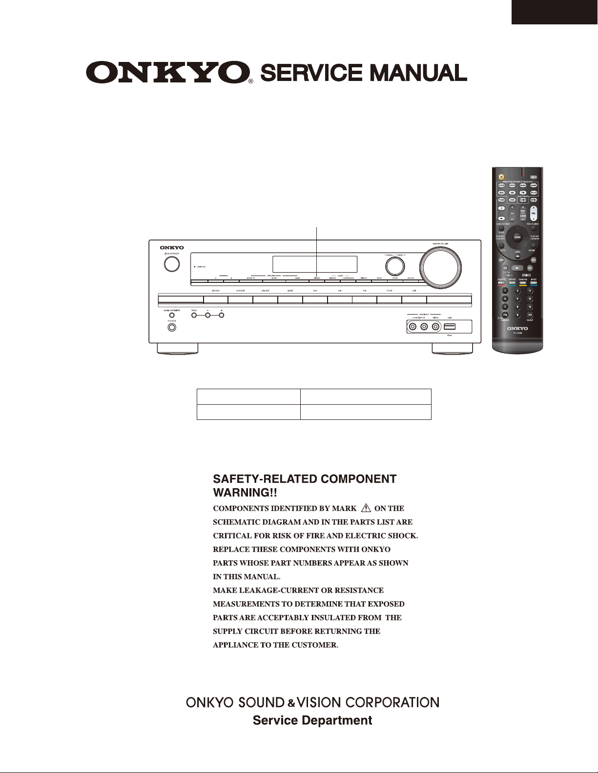
AV RECEIVER
MODEL HT-R391(B)
North American and Brazilian models ---> “DIMMER”
Asian models ---> “RT/ PTY/ TP”
HT-R391
Ref. No. 4380
022012
Black model for HT-S3500
B MDC, B MDS
B MMK, B MMQ
120V AC, 60Hz
220-240V AC, 50/60Hz
RC-799M
Page 2
SERVICE PROCEDURE-1
1. Replacing the fuses
This symbol located near the fuse indicates that the
fuse used is slow operating type, For continued protection against
fire hazard, replace with same type fuse, For fuse rating, refer to
the marking adjacent to the symbol.
Ce symbole indique que le fusible utilise est e lent.
Pour une protection permanente, n'utiliser que des fusibles de meme
type. Ce demier est indique la qu le present symbol est apposre.
REF NO. PART NAME DESCRIPTION PART NO. REMARKS
F6901
F6902
F901
F901 or
F901
F901 or
F9001
FUSE
FUSE
FUSE
FUSE
FUSE
FUSE
FUSE
8A-T/UL-ST2
8A-T/UL-ST2
8A-UL/T-233
8A-T/UL-ST2
4A-SE-EAK
4A-SE-TL250V
5A-UL-125V
252261GR
252261GR
252329GR
252261GR
252077GR
252277GR
252385T
!
!
<MDC, MDS>
!
<MDC, MDS>
!
<MMK, MMQ>
!
<MMK, MMQ>
!
!
HT-R391
2. Safety check out
(U.S.A. model only)
After correcting the original service problem, perform the following safety check before releasing the unit to the customer.
Leakage current Check
Measure the leakage current to a known earth ground (water pipe or conduct etc.) by connecting a leakage current
tester between the earth ground and exposed metal parts of the unit (input/output ground terminals, screw heads or metal overlays etc.).
Plug the power supply cord directly into a 120Vac 60Hz wall socket and turn ON/STANDBY button on.
Any current measured must not exceed 0.5mA.
3. To initialize the unit
1. Press ON/STANDBY button while pressing down VCR/DVR button when the unit is POWER ON, then the FL displays
"CLEAR", and turn to STAND-BY.
Preset memory and each mode stored in the memory, are initialized and will return to the factory settings.
2. Remove power cord from wall outlet.
ON/STANDBY
Clear
VCR/DVR
Stand-by
Page 3
SERVICE PROCEDURE-2
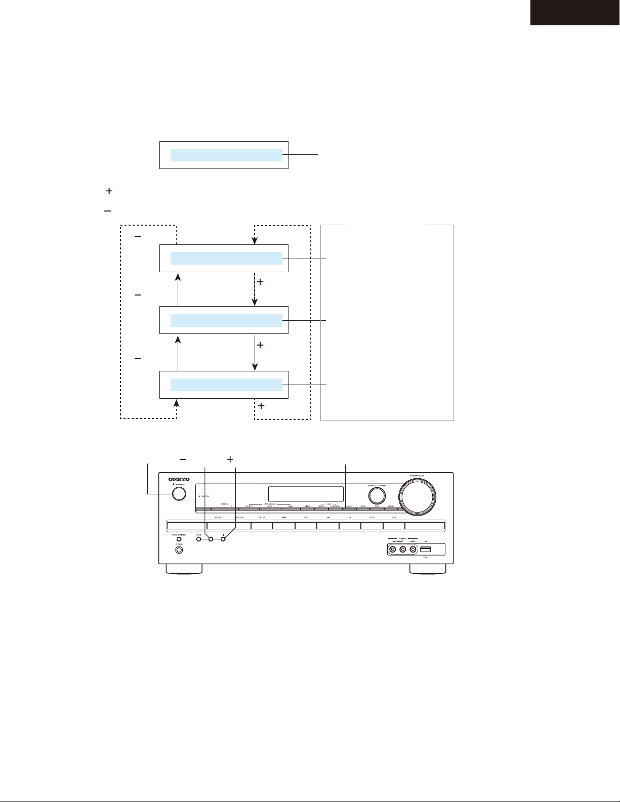
4. To check version of each Firmware
1. Press ON/STANDBY (Power On)
2. Press DISPLAY + ON/STANDBY.
e.g.
M:1.00/ 1 1 Z 2 2 ALU
3. Press (Tone) ---> Forward
Press (Tone) ---> Reversed.
(TONE)
e.g.
(TONE)
e.g.
M:1.00/ 1 1 Z 2 2 ALU
D:1.00/ 1 1 Z 0 5 aL
HT-R391
Version of Main Microprocessor displayed
only for 3 seconds.
Version displayed
only for 3 seconds.
Main Microprocessor
(TONE)
DSP
(TONE)
e.g.
O:1.00/ 1 1 Z 0 2 AL
4. Press ON/STANDBY (Power Off).
ON/STANDBY
(TONE) (TONE)
(TONE)
HDMI/Video Microprocessor
(TONE)
DISPLAY
Page 4
TX-SR313/ HT-R358/391/558/591/ HT-RC430
DEBUG MODE-1
AUDIO DEBUG MODE-1/5
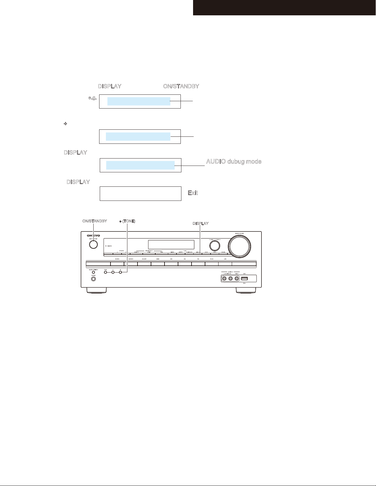
The operations of DSP and DIR etc are able to checked by the information displayed on FL in this debug mode.
This information will help to analysing digital audio no sound trouble.
To set in Debug mode
1. Press and hold down DISPLAY button, then press ON/STANDBY button.
2. Press + (TONE) button while the version number of microprocessor is displayed.
3. Press DISPLAY button while the version number of DSP is displayed.
11. Press DISPLAY button.
e.g.
e.g.
e.g.
e.g.
M1.06/1 2 4 1 7 A E
D1.05/1 2 3 2 7 A EA
4D48K1N 0 F F P o0
The version number of microprocessor is displayed
only for 3 seconds.
The version number of DSP is displayed
only for 3 seconds.
AUDIO dubug mode
The status of DSP and DIR etc
will be displayed.
Exit
ON/STANDBY
+ (TONE)
DISPLAY
Page 5
DEBUG MODE-2
AUDIO DEBUG MODE-2/5
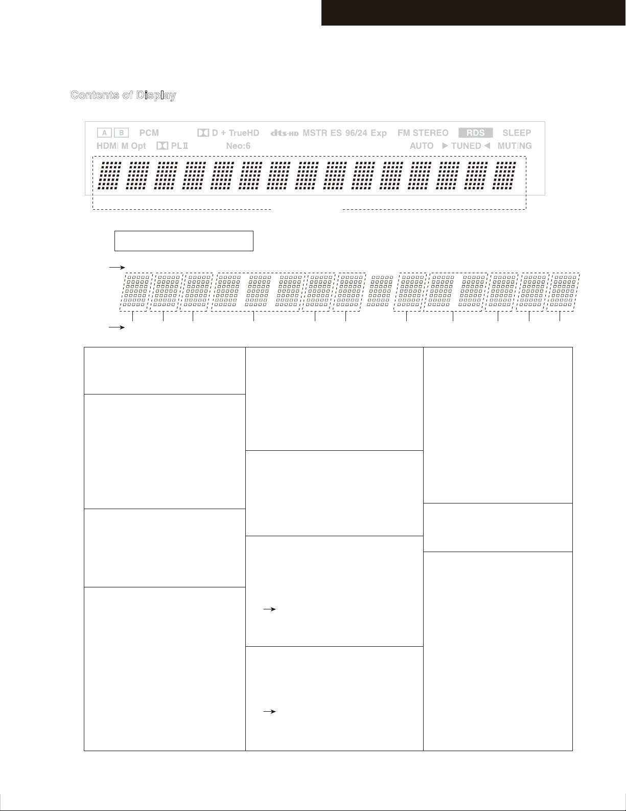
Contents of Display
TX-SR313/ HT-R358/391/558/591/ HT-RC430
FL Display
Display area
e.g.
0A0002:__:00__
Number of
digits
Number of
Parameters
1. DIR INPUT LOCK/UNLOCK
E:UNLOCK
:LOCK
2. DIR INPUT RX
0:None
1:COAX1
2:COAX2
3:OPT1
4:OPT2
5:FRONT
8:HDMI1
9:HDMI2
3. DIR/ADC,FIX MODE
D:Digital(SPDIF)
A:Analog
M:AnalogMultich
p:PCM FIXED
d:DTS FIXED
4. Sampling Freq,Emphasis
32K: 32 kHz w/o Emphasis
44K: 44.1kHz w/o Emphasis
48K: 48 kHz w/o Emphasis
64K: 64 kHz
88K: 88.2kHz
96K: 96 kHz
176:176.4kHz
192:192 kHz
32e: 32 kHz w Emphasis
44e: 44.1kHz w Emphasis
48e: 48 kHz w Emphasis
1 141312106 87432 5 9 11 15
1 3 7542 6 8 9 10 11
5. DIR DETECT TYPE
0:Analog
1:PCM
2:Not PCM
3:Data
4:DTS CD(Not used)
5:Multich
6:Not Decided
6. CODEC CLOCK MODE
N:Normal
U:Up Sampling
H:High Sampling(Double Rate)
D:Down Smapling
Q:Quad Rate
7. DSP PORT
bit0:NIC
bit1:DEC
bit2:BUSY
bit3:EXEC WAIT
Refer to “DEBUG MODE-3”
Description of the DSP PORT
(NIC/DEC/SPI Busy/Exec wait)
8. DSP SEQUENCE
00-FE:NotFree
2D:Mute Control
FF:Free
Refer to “DEBUG MODE-4, -5”
Description of the
DSP Sequence
9. DSP DETECT FORMAT
P:PCM(Analog)
D:Dolby Digital
d:DTS
A:AAC
d:DTS
A:AAC
S:DSD
p:DolbyDigital+
T:TrueHD
H:DTSHD High Resolution
M:DTSHD MaterAudio
?:UNKNOWN
10. DSP DECODE OK
o:OK
x:NG
11. Mute
1:Selector
2:Effector
4:DSP
8:DIR
Page 6
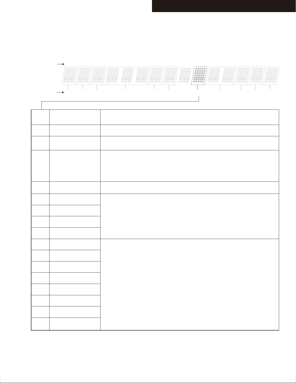
DEBUG MODE-3
AUDIO DEBUG MODE-3/5
Description of the DSP PORT(NIC/DEC/SPI Busy/Exec wait)
TX-SR313/ HT-R358/391/558/591/ HT-RC430
Number of
digits
Number of
Parameters
Display
contents
0
1
2
3
4
5
1 141312106 87432 5 9 11 15
1 3 7542 6 8 9 10 11
Internal state Inferred state
Stable state
NIC
DEC
NIC+DEC
SPI Busy
SPI Busy + NIC
If the stop remains "1" is indicated, it is possible that there is an abnormality in
the connection between the microcomputer and the NIC.
Please check if the input signal Dolby / DTS / AAC / PCM from Coax or OPT.
If the stop remains “2” is indicated, it is possible that there is an abnormality
in the connection between the DIR and the DSP.
There is a case of "2" for the state to stop or pause playback equipment.
And it is normal.
If the stop remains "3" is indicated, it is possible that there is an abnormality in
the connection between the microcomputer and the NIC.
If the stop in these numbers, it is possible that there is an abnormality in
the connection between the DSP and the microcomputer.
SPI Busy + DEC
6
SPI Busy + NIC + DEC
7
Exec wait
8
Exec wait + NIC
9
Exec wait + DEC
A
Exec wait + NIC+DEC
B
Exec wait + SPI Busy
C
Exec wait + SPI Busy
D
+ NIC
Exec wait + SPI Busy
E
+ DEC
Exec wait + SPI Busy
F
+ NIC + Dec
If you stop at these numbers, please check the DSP Sequence.
Page 7
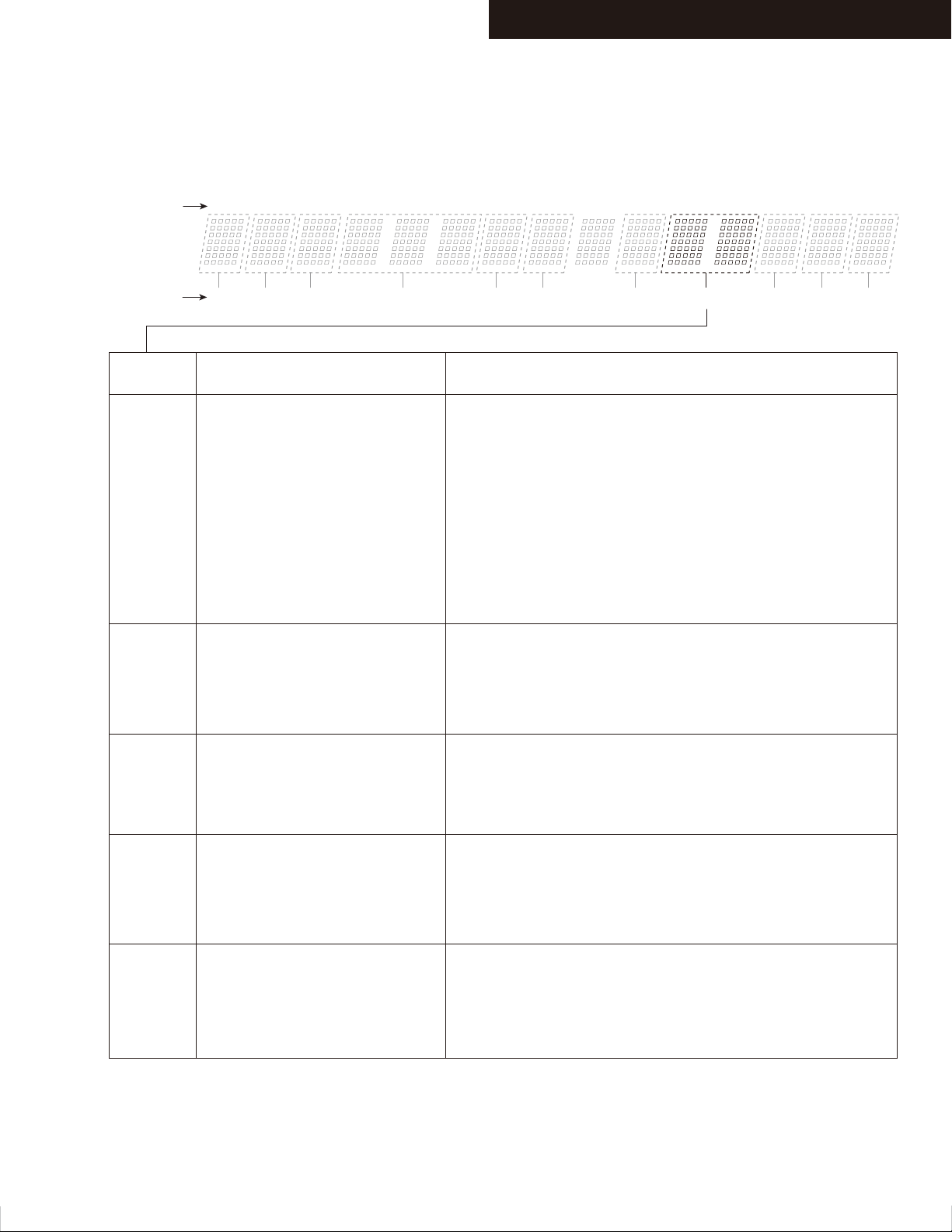
DEBUG MODE-4
AUDIO DEBUG MODE-4/5
Description of the DSP Sequence(1/2)
TX-SR313/ HT-R358/391/558/591/ HT-RC430
Number of
digits
Number of
Parameters
Display
contents
Stop at "03"
is indicated.
Stop at "05"
is indicated.
1 141312106 87432 5 9 11 15
1 3 7542 6 8 9 10 11
Inferred state
Have not been able to communicate
between the microcontroller and
the DSP.
Have not been able to write from
the boot loader of the DSP.
Possible Causes
1.There is a problem with the connection between the FlashROM and
the DSP, and the SDRAM.
2.Power is not supplied to the DSP.
3.Operation clock is not input to the DSP.
4.Reset port of the DSP is not connected.
5.There is a problem with the line of communication between the
microcontroller and DSP.
6.DSP is broken or Microcomputer.
7.Program has not been successfully written to the Flash ROM. Or the
program is not written.
8.Communication port (such as DIR) other devices are connected to t
he SPI mode is broken short. Terminals are short-circuited.
1.Program is not written correctly to Flash ROM.
2.DSPSDO line of microcomputer is interrupted somewhere.
3.There is a problem with the FlashROM (or SDRAM) of DSP.
4.DSP is broken or Microcomputer.
5.Upper address bus of Flash ROM is not connected properly.
Stop at "08"
is indicated.
Stop at
"09 - 0C"
is indicated.
Stop at "17"
is indicated.
While running the boot loader of DSP,
the main program is not running.
Main program of DSP is not working
properly.
There is a possibility that the power is
turned off during the S / PDIF Update.
1.SDRAM is broken or Flash ROM.
2.Upper address bus of Flash ROM is not connected properly.
3.Program is not written correctly to Flash ROM.
4.There is a possibility that the power is turned off during
the S / PDIF Update.
1.SDRAM is broken or Flash ROM.
2.Upper address bus of Flash ROM is not connected properly.
3.Program is not written correctly to Flash ROM.
4.There is a possibility that the power is turned off during
the S / PDIF Update.
Solution :
Hold down the VCR/ DVR when the power is turned on, press the
On/Standby key. (Clear)
When out of the state of S / PDIF Update, please press the
On/Standby key.
Page 8
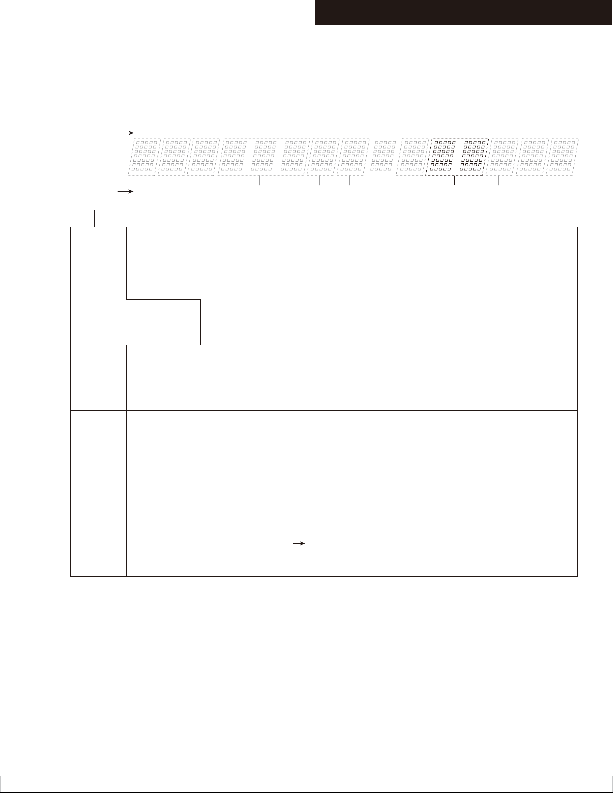
DEBUG MODE-5
AUDIO DEBUG MODE-5/5
Description of the DSP Sequence(2/2)
TX-SR313/ HT-R358/391/558/591/ HT-RC430
Number of
digits
Number of
Parameters
Display
contents
Stop at “21”, to return to the
previous display after a while.
Format display indicator flashes.
Stop at
"22-24"
is indicated.
Stop at
"30-33"
is indicated.
1 141312106 87432 5 9 11 15
1 3 7542 6 8 9 10 11
Inferred state
Main program of DSP is not working
properly.
main program of DSP is not working
properly.
The audio signal is not input.
main program of DSP is not working
properly.
The audio signal is not input.
Possible Causes
1.SDRAM(or Flash ROM) is broken.
2.Upper address bus of Flash ROM is not connected properly.
3.Program is not written correctly to Flash ROM.
4.Operation clock to the DSP is not a predetermined value.
1.SDRAM(or Flash ROM) is broken.
2.Upper address bus of Flash ROM is not connected properly.
3.Program is not written correctly to Flash ROM.
4.Operation clock to the DSP is not a predetermined value.
5.Audio clock to the DSP is not a predetermined value.
1.SDRAM(or Flash ROM) is broken.
2.Upper address bus of Flash ROM is not connected properly.
3.Program is not written correctly to Flash ROM.
Stop at
"26-2F"
is indicated.
Stop at "FF"
is indicated.
DSP settings has failed.
The DSP is functioning properly.
There is no sound even though it is
the display of "FF".
1.SDRAM(or Flash ROM) is broken.
2.Upper address bus of Flash ROM is not connected properly.
3.Program is not written correctly to Flash ROM.
All settings are completed, DSP has started normal operation.
Refer to “DEBUG MODE-3”
Description of the DSP PORT
(NIC/DEC/SPI Busy/Exec wait)
Page 9
TX-SR313/ HT-R358/391/558/591/ HT-RC430
DEBUG MODE-6
HDMI DEBUG MODE-1/6
HDMI-related operations can be checked to some extent by displaying HDMI debug mode.
To enter this mode
Hold down DISPLAY button for 3 seconds. Information display will last for about 8 seconds.
Content of Display
1
Resolution display
Input resolution Output resolution
0
80i
1
1
List of standard resolution
4 8 0 i / 6 0
4 8 0 p / 6 0
1 0 8 0 i / 6 0
7 2 0 p / 6 0
1 0 8 0 p / 6 0
2 4 0 p / 6 0
# 4 8 0 i / 6 0
6
/
0
14
1312106 87432 5 9 11
1
# 5 7 6 i / 5 0
# 5 7 6 p / 5 0
# 2 8 8 p / 5 0
1 0 8 0 p / 2 4
1 0 8 0 p / 2 5
1 0 8 0 p / 3 0
V G A
14
1312106 87432 5 9 11
80
1 0
6
/
i
5 7 6 p 2 0 0
5 7 6 i 2 0 0
4 8 0 p / 6 0
4 8 0 p 2 4 0
4 8 0 i 2 4 0
* 4 8 0 p / 6 0
* 5 7 6 p / 5 0
1312106 87432 5 9 11
0
14
# 4 8 0 p / 6 0
# 2 4 0 p / 6 0
5 7 6 i / 5 0
5 7 6 p / 5 0
1 0 8 0 i / 5 0
7 2 0 p / 5 0
1 0 8 0 p / 5 0
2 8 8 p / 5 0
1 0 8 0 i 1 0 0
7 2 0 p 1 0 0
5 7 6 p 1 0 0
5 7 6 i 1 0 0
1 0 8 0 i 1 2 0
7 2 0 p 1 2 0
4 8 0 p 1 2 0
4 8 0 i 1 2 0
7 2 0 p / 2 4
7 2 0 p / 2 5
7 2 0 p / 3 07 2 0 p / 3 0
Page 10
DEBUG MODE-7
HDMI DEBUG MODE-2/6
Display of Input resolution
DVI input signal
VGA input signal
No input
Display of Output resolution
TX-SR313/ HT-R358/391/558/591/ HT-RC430
4 8 0 I / 6 0
1
4 8 0 P / 6 0
1
i / p will be capitalized.
V G A
1
Display the ” ” in column 1
U n k n o w n
1
14
1312106 87432 5 9 11
14
1312106 87432 5 9 11
14
1312106 87432 5 9 11
14
1312106 87432 5 9 11
For a video processor
DVI input signal
VGA input signal
RSEN is OFF
EDID_READ is NG
Via VSP
VSP skip
1 0 8 0 i / 6 0
1
Display the ” ” in column 4
1 0 8 0 i / 6 0
1
4 8 0 I / 6 0
1
4 8 0 P / 6 0
1
i / p will be capitalized.
4 8 0 p / 6 0
1
Display the ” ” in column 5
4 8 0 p / 6 0
1
4 8 0 p / 6 0
1
14
1312106 87432 5 9 11
14
1312106 87432 5 9 11
14
1312106 87432 5 9 11
14
1312106 87432 5 9 11
14
1312106 87432 5 9 11
14
1312106 87432 5 9 11
Display the ” ” in column 14
#
14
1312106 87432 5 9 11
Display the ” # ” in column 14
Resolution Error
No output
(Signal output destination
can not be found.)
Hot-plug of Sink equipment
can not be detected.
4 8 0 p / 6 0
1
Display the ” x ” in column 14
x
14
1312106 87432 5 9 11
- - - - - -
1
14
1312106 87432 5 9 11
O F F
1
14
1312106 87432 5 9 11
Page 11
DEBUG MODE-8
HDMI DEBUG MODE-3/6
4K Upscaling
Display of input resolution
1 0 8 0 i / 6 0
1
Display of Output resolution
TX-SR313/ HT-R358/391/558/591/ HT-RC430
14
1312106 87432 5 9 11
1
List of resolution
3 8 4 0 x 2 1 6
1
3 8 4 0 x 2 1 6
1
3 8 4 0 x 2 1 6
1
4 0 9 6 x 2 1 6
1
Resolution Error
EDID_READ_NG
x
p
/
0 p / 3
0 p / 2
0 p / 2
0 p / 2
3 8 4 0 x 2 1 6
1
3 8 4 0 x 2 1 6
1
14
1312106 87432 5 9 11
If the three-digit numbers are refrate
14
131211
0
14
1312106 87432 5 9 11
5
14
1312106 87432 5 9 11
4
14
1312106 87432 5 9 11
4
14
1312106 87432 5 9 11
0 p / 3
0 p / 3
x
0
14
1312106 87432 5 9 11
0
#
14
1312106 87432 5 9 11
Page 12
DEBUG MODE-9
HDMI DEBUG MODE-4/6
TX-SR313/ HT-R358/391/558/591/ HT-RC430
Resolution display
Status Display
3D format
INPUT/OUTPUT
Display of Input resolution
RSEN OFF
EDID READ NG
Resolution Error
1 0 8 0 p / 2 4
1
(
3 D
H D M I t4 4 4 3 6 b i
1
F r a m cP a
1
I N : UO
1
1 0 8 0 p / 2 4
1
H D M I t4 4 4 3 6 b i
1
Display the ” # ” in column 9
1 0 8 0 p / 2 4
1
k i n ge
T
:
(
Display the ” ” in column 14
#
(
Display the ” x ” in column 13
)
14
1312106 87432 5 9 11
14
1312106 87432 5 9 11
14
1312106 87432 5 9 11
14
1312106 87432 5 9 11
3 D
3 D
)
14
1312106 87432 5 9 11
14
1312106 87432 5 9 11
)
x
14
1312106 87432 5 9 11
Status
Input Mode
Input Color
Deep Color
HDMI input
DVI input
No input
RGB
422
444
24bit
30bit
H D M I t4 4 4 3 6 b i
1
1312106 87432 5 9 11
D V I t4 4 4 3 6 b i
1
1312106 87432 5 9 11
- - - t4 4 4 3 6 b i
1
1312106 87432 5 9 11
H D M I tR G B 3 6 b i
1
1312106 87432 5 9 11
H D M I t4 2 2 3 6 b i
1
1312106 87432 5 9 11
H D M I t4 4 4 3 6 b i
1
1312106 87432 5 9 11
H D M I tR G B 2 4 b i
1
1312106 87432 5 9 11
H D M I tR G B 3 0 b i
1
1312106 87432 5 9 11
14
14
14
14
14
14
14
14
36bit
H D M I tR G B 3 6 b i
1
1312106 87432 5 9 11
14
Page 13
DEBUG MODE-10
HDMI DEBUG MODE-5/6
3D format
Frame Packing
TX-SR313/ HT-R358/391/558/591/ HT-RC430
F r a m __ P a k i n ge c
1
14
1312106 87432 5 9 11
Field alternative
Line alternative
Side-by-Side(Full)
L+depth
L+depth + graphics
Side by Side(Harf)
Top and Bottom
unknown
F _ a l _e r n t i v et a
1
L _ a l _e r n t i v et a
1
S i d e _y S i e ( F )b d
1
L d e _t h _ _ _ _ _p _
1
L d e ct h g a p h ip r
1
S i d e _y S i e ( H )b d
1
T o p - mn d - o t t oa B
1
U N K N _W N _ _ _ _ _O _
1
14
1312106 87432 5 9 11
14
1312106 87432 5 9 11
14
1312106 87432 5 9 11
14
1312106 87432 5 9 11
14
1312106 87432 5 9 11
14
1312106 87432 5 9 11
14
1312106 87432 5 9 11
14
1312106 87432 5 9 11
INPUT/ OUTPUT
I N : O T :U
1
14
1312106 87432 5 9 11
Page 14
DEBUG MODE-11
HDMI DEBUG MODE-6/6
PC resolution
Input Resolution
TX-SR313/ HT-R358/391/558/591/ HT-RC430
1 0 2 4 x 7 6 p / 6 08
1
14
1312106 87432 5 9 11
Output Resolution
Display of Input resolution
Horizontal resolution
DVI input
HDMI input
Three-digit numbers
are Referat
No input
Display of Output resolution
Horizontal resolution
1 0 2 4 x 7 6 p / 6 08
1
1
Display uppercase
P/I
Display lowercase
p/i
1
x p /
Vertical resolution
1 0 2 4 x 7 6 P / 6 08
1
1 0 2 4 x 7 6 p / 6 08
1
1 0 2 4 x 7 6 P 1 2 08
1
U N K N O W N
1
x p /
Vertical resolution
1312106 87432 5 9 11
Referat
1312106 87432 5 9 11
Referat
14
1312106 87432 5 9 11
14
14
1312106 87432 5 9 11
14
1312106 87432 5 9 11
14
1312106 87432 5 9 11
14
1312106 87432 5 9 11
14
DVI output
HDMI output
Display”-----”
Three-digit numbers
are Referat
EDID READ NG
Resolution through
INPUT/ OUTPUT
Display uppercase
P/I
Display lowercase
p/i
Display the ” # ” in
column 13
Display the ” x ” in
column 13
I N : O T :U
1
1 0 2 4 x 7 6 P / 6 08
1
14
1312106 87432 5 9 11
1 0 2 4 x 7 6 p / 6 08
1
14
1312106 87432 5 9 11
- ----
1
14
1312106 87432 5 9 11
1 0 2 4 x 7 6 P 1 2 08
1
14
1312106 87432 5 9 11
1 0 2 4 x 7 6 P / 6 08 #
1
14
1312106 87432 5 9 11
1 0 2 4 x 7 6 P / 6 08 x
1
14
1312106 87432 5 9 11
14
1312106 87432 5 9 11
Page 15

TX-SR313/ NR414/ HT-R391/358/558/591/758/ RC430/440
OPERATION CHECK-1
1.OPERATION CHECK(1/2)
1-1. OPERATIONS OF VOLTAGE-DETECTION PROTECTORS.
See “OPERATION CHECK-3, -5” for TEST MODE operation.
NOTE: Don't connect load nor short speaker terminals.
a. Change the state to "TEST-4-21".
b. It tests by being automatic in order of TEST4-21(FL+) → 22(FR-) → 23(C+) → 24(SL-)
→ 25(SR+) → ( 26(SBL-) → 27(SBR+) ). It becomes the display of "TEST-4-35."
c. It will complete, if displayed on FL TUBE as "TEST-4-35."
d. Check operation of voltage-detection of subwoofer channnel. (HT-R391/358 only)
Change the state to "TEST-1-00".
The speaker relay is OFF immediately after D.C. +1.5v 3v is put at J4082 J4090 to check SW.
The same as above when D.C. -1.5v 3v is put at each place.
NOTE1: Limit time to apply voltage is 0.5-1.0 seconds each channel.
When protection operation does not occur at once, try several times.
NOTE2: Don't connect load nor short speaker terminals.
NOTE3: The relay shall recover in one second in "TEST-1-00". So it shall not be hold OFF.
1-2. OPERATIONS OF CURRENT-DETECTION PROTECTORS
See “OPERATION CHECK-3, -4” for TEST MODE operation.
a. Change the state to "TEST-4-35".
Even if you connect 3-ohm load for every channel of L, R, C, SL, SR, SBL,SBR and SWch, a relay should not cut off.
If 1-ohm load is connected for every channel of L, R, C, SL, SR,SBL,SBR and SWch, a relay should hold the state of ON.
1-3. CONFIRMATION OF RDS (RADIO DATA SYSTEM) OPERATION (Applied to MPP/MPB type)
a. Input 98MHz,30dBμ signal modurated with RDS data.
b. When a PS information is received, the name of the station "RDS TEST" shall be displayed within 2 seconds instead of the frequency.
1-4. CONFIRMATION OF HEAD PHONE OPERATION.
Confirm the Listening Mode is automatically switched to "STEREO" mode when headphones plug is inserted into the PHONES jack.
1-5. COMFIRMATION OF USB(Except of HT-R358)
See “OPERATION CHECK-3, -4” for TEST MODE operation.
a. Connect ipod to AVR USB port.
b. When set to TEST-3-10, confirm that the display of AVR change "connecting" to "press Push [MODE] button ...." or "iPod"
after few seconds.
The following iPod models can be used for inspection.(The above-mentioned operation is not done excluding the following items.)
iPod classic, 3G nano, 4G nano, 5G nano
1-6. CONFIRMATION OF OUTPUT SENSOR AND THERMAL SENSER.
See “OPERATION CHECK-3, -5” for TEST MODE operation.
a. Set the TEST MODE to "TEST-4-36" and "TEST-4-37".
After light "FM STEREO" on FL display, the relays RL691/692 is OFF and "FM STEREO"is off .(TEST4-37 is only for HT-R591.)
b. Push ON/Standby button while pushing down DISPLAY button to display CPU PROGRAM version.
Push TONE button while displaying CPU PROGRAM version to display value of temparature sensor.
Confirm outside temperature ±20C is displayed immediately after energizing.
Note that the error margin is caused by the rise of the temperature of the heat sink when time passes.
No singal condition (Ex. Display)
>00 034 F:x S:H
Voltage
of VOLH port
Temparature
of thermal sensoor
FAN condition
x: Stop
L: Low speed
M: Mid speed
H: High speed
Amplifier power
supply voltage condition
H: High-B
L: Low-B
Page 16
TX-SR313/ NR414/ HT-R391/358/558/591/758/ RC430/440
OPERATION CHECK-2
1.OPERATION CHECK(2/2)
1-7. CONFIRMATION OF HDMI MAIN OUTPUT OSD(ON SCREEN DISPLAY) OPERATION
a. When SETUP button is pushed, confirm that setup menu is displayed in HDMI Out.
b. Confirm that specified operations for ENTER(with 4-cursor) buttons are made.
1-8. CONFIRMATION OF HDMI AUDIO OPERATION.
See “OPERATION CHECK-3, -6” for TEST MODE operation.
CONFIRMATION OF HDMI I2S SIGNAL
a. Input the one of these signals below from HDMI1 terminal.
DTS-HD MasterAudio 7.1ch
Dolby TrueHD 7.1ch
LPCM 7.1ch
b. Change the state to TEST 6-00. Confirm the signal is output from L/R,SW/C,SL/SR,SBL/SBR.
c. When TEST 6-08, confirm the sound(HDMI1 input) outputs from the TV.
CONFIRMATION OF HDMI SPDIF SIGNAL
d. SPDIF signal is input from HDMI terminal.
e. When TEST 6-06, confirm the sound(HDMI IN1) outputs from the speaker.
f. When TEST 6-07, confirm the sound(BD/DVD analog input) outputs from the TV.(VIDEO is HDMI1)
CONFIRMATION OF HDMI DSD SIGNAL
g. When TEST 6-10,11,12, confirm the sound of DSD 5.1ch input HDMI IN 3, output from the speaker.
1-9. VIDEO FUNCTION CHECK
See “OPERATION CHECK-3, -6” for TEST MODE operation.
a. Confirm Video output signal as shown Table 2, while Video signal are input as shown Table 1.
NOTE: Confirm the HDMI path at 1080p signal.
Table 1
Input
BD/DVD
VCR/DVR
CBL/SAT
GAME
PC
AUX
Composite Video
A
B
C
D
H
E
Component
IN1
--IN2
---
---
---
F
No
G
No
No
No
HDMI
IN1
IN2
IN3
IN4
IN5
IN6
J
K
L
M
N
O
Table 2
Test mode
5-05(BD/DVD)
5-06(VCR/DVR)
5-07(CBL/SAT)
5-08(GAME)
5-09(PC)
5-10(AUX)
Composite Video
ZVCR out
A
--C
D
H
E
Monitor out
A
B
C
D
H
E
Component
OUT
F
--G
---
---
---
HDMI
OUT
J
K
L
M
N
O
b. OPERATIONS OF VIDEO SIGNAL-DETECTION
Set the TEST MODE to "TEST-5-00".
Confirm that "RDS" of FL TUBE lights, when the component video signal is input.
1-10. MISCELLANEOUS
See “OPERATION CHECK-3” for TEST MODE operation.
a. Please confirm LED and FL displaying by the FL test mode. And confirm the destination setting. ---> See to"OPERATION CHECK-3".
b. Confirm Key Operation.
Change the state to KEY TEST under TEST MODE described in Section 4-2. to confirm each key operation.
c. Confirm the version of each firmware.--->See to" SERVICE PROCEDURE-2".
d. Confirm the firmware combination check.
e. Confirm the DSP flash check.(Except TX-NR414, HT-R758 )
When it is normal, FL display indicate "A:OK B:OK"
Page 17
TX-SR313/ NR414/ HT-R391/358/558/591/758/ RC430/440
OPERATION CHECK-3
2.TEST MODE(1/4)
2-1.TEST MODE FOR MODEL, DESTINATION AND FL DISPLAY
NOTE: If VOL value is not 25(initial setting), test mode cannot be set.
a. Push ON/STANDBY key while pushing down TV/CD button button to display "TEST-".
b. Then push DIMMER(RT/PTY/TP) button and get the FL test mode.
c. In the FL test mode, TONE - button is FL TEST UP and TONE + button is FL TEST DOWN.
d. REC OUT and ZONE2 button's originally operation can't work when it is in FL test mode.
e. The contents of the step are as follows.
1. Lit all segment
2. Lit 'FEDCBA987654321'.
3. Lit a even number segment
4. Lit an odd number segment
5. The Destination is displayed. Please see the below for detail.
f. To close the FL test, push POWER button.
S R 313 Dx 2 0 0 0
MODEL Name
MODEL
FL DIS Name
Destination
ABCD
MODEL
FL DIS Name
Destination
ABCD
TX-SR313
Dx
2000
TX-NR414
Dx
2000
SR313
NR414
Destination
Dx: USA/Canada
xx: OTHER
HT-RC430
RC430
xx
8000
xx
8000
2020xx8020
Dx
2002
HT-R758
HT758
Dx
A BCD
A:Value of AD port of BAND
B:Value of AD port of INIT1
C:Value of AD port of INIT2
D:Value of AD port of INIT3
HT-R391
HT391
Dx
2020xx8020
HT-R358
HT358
xx
8022
HT-R358
HT358
xx
8022
HT-RC440
RC440
Dx
2002
HT-R558
HT558
xx
8026
HT-R658
HT658
xx
8024
2-2. TEST MODE FOR OPERATION
a. Push STANDBY/ON button while pushing down TV/CD button to display "TEST-_".
b. Next, if the following keys are pushed, it becomes a each TEST MODE.
c. In the test mode, (TONE)- button is TEST MODE DOWN and (TONE)+ button is TEST MODE UP.
d. "TEST-1-00" and "TEST-1-01" are used to check a protection circuit, and the relay recovered in one second.
TEST MODE
Test mode No. --->
Button --->
TX-NR414
/HT-R758
Others
1-00 2-00 3-00 4-00 5-00 6-00
BD/DVD
BD/DVD
CBL/SAT GAME PC AUX TV/CD
VCR/DVR
CBL/SAT
GAME
AUX
TV/CD
HT-R591
HT591
Dx
2028xx8028
KEY TEST
MEMORY
(CINEMA FILTER)
IDLING
TIMER
TUNING MODE
(LATE NIGHT)
FL TEST
DIMMER
(RT/PTY/TP)
FIRMWARE
VERSION
TONE
TEST MODE
FIRMWARE
COMBINATION
CHECK
ENTER
CHECK SUM
When the MPU version
is displayed, push
"MEMORY(CINEMA FILTER)"
DSP FLASH CHECK
When the DSP version is
displayed, push "BD/DVD"
Page 18

TX-SR313/ NR414/ HT-R391/358/558/591/758/ RC430/440
OPERATION CHECK-4
2.TEST MODE(2/4)
2-2. TEST MODE FOR OPERATION(Continue)
e. Test mode is as follows.
TEST
Analog Input
No
[Rec Sel]
(Zone2)
1-00
BD/DVD (Off)
1-01
BD/DVD (Off)
1-02
BD/DVD (Off)
2-00
BD/DVD (Off)
2-01
BD/DVD (Off)
2-02
BD/DVD (Off)
2-03
Multi channel
2-05
BD/DVD (Off)
2-06
BD/DVD (Off)
2-07
BD/DVD (Off)
2-08
BD/DVD (Off)
2-09
BD/DVD (Off)
2-10
BD/DVD (Off)
2-11
VCR/DVR (Off)*2
2-12
VCR/DVR (Off)*2
2-13
CBL/SAT (Off)
2-14
GAME (Off)
2-15
AUX (Off)
2-16
BD/DVD (Off)
2-17
BD/DVD (Off)
2-18
TV/CD (Off)
2-19
BD/DVD (Off)
2-20
BD/DVD (Off)
2-21
BD/DVD (Off)
2-22
BD/DVD(Source)
2-23
MIC
2-24
MIC
2-25
AUX(Off)
2-26
PC (Off)
3-00
FM/Source
3-01
TV/CD
3-02
TV/CD
3-03
TV/CD
3-04
TV/CD (Off)
3-05
SXM (Off)
3-06
PORT (Source)
3-10
USB/(Source)
3-11
NET/(Source)
3-12
NET/(Source)
3-13
NET/(Source)
3-14
NET/(Source)
3-15
NET/(Source)
3-16
NET/(Source)
3-17
NET/(Source)
3-18
NET/(Source)
Listening Mode/
Input Format
Direct
Direct
Direct
Stereo(Direct)
Stereo(Direct)
DVD Direct
Multich Amp Test
ADC DSP 8ch Thru.
ADC DSP 8ch Thru.
ADC DSP 7ch Thru.
ADC DSP 8ch Thru.
ADC DSP 8ch Thru.
ADC DSP 8ch Thru.
Automatic
Automatic
DIR DSP 8ch Thru
DIR DSP 8ch Thru
DIR DSP 8ch Thru
DIR DSP 8ch Thru
DIR DSP 8ch Thru
Automatic
DIR DSP 8ch Thru
DIR DSP 8ch Thru
DIR DSP 8ch Thru
DIR DSP 8ch Thru
ADC DSP 8ch Thru.
ADC DSP 8ch Thru.
DIR DSP 8ch Thru
DIR DSP 8ch Thru
Stereo(Direct)
Stereo(Direct)
Stereo(Direct)
Stereo(Direct)
ALL CH STEREO
Stereo(Direct)
ADC DSP 8ch Thru.
Stereo(Direct)
Stereo(Direct)
Stereo(Direct)
Stereo(Direct)
Stereo(Direct)
Stereo(Direct)
Stereo(Direct)
Stereo(Direct)
Stereo(Direct)
VIDEO
Input
BD/DVD
BD/DVD
BD/DVD
BD/DVD
BD/DVD
BD/DVD
BD/DVD
BD/DVD
BD/DVD
BD/DVD
BD/DVD
BD/DVD
BD/DVD
VCR/DVR*2
VCR/DVR*2
CBL/SAT
GAME
AUX
BD/DVD
BD/DVD
BD/DVD
BD/DVD
BD/DVD
BD/DVD
BD/DVD
BD/DVD
BD/DVD
AUX
PC
DVD
DVD
DVD
DVD
DVD
DVD
PORT
Last
Last
Last
Last
Last
Last
Last
Last
Last
Compo-
nent V
IN1
IN1
IN1
IN1
IN1
IN1
IN1
IN1
IN1
IN1
IN1
IN1
-
-
-
-
-
-
-
DVD
DVD
DVD
DVD
DVD
DVD
DVD
-
-
DVD
DVD
DVD
DVD
DVD
DVD
-
-
-
-
-
-
-
-
-
-
HDMI
IN1
IN1
IN1
IN1
IN1
IN1
IN1
IN1
IN1
IN1
IN1
IN1
IN1
IN2
IN2
IN3
IN4
-
-
-
IN2
IN2
IN2
IN3
IN3
IN1
IN1
-
-
IN1
IN1
IN1
IN1
IN1
IN1
-
-
-
-
-
-
-
-
-
-
12V
Trigger
A
B
C
-
-
-
-
-
-
-
-
-
Digital Input
/Output
-
-
-
-
-
-
-
-
-
-
-
-
-
*OPT1
*COAX1
*OPT1
OPT1
COAX1
COAX1
*OPT2
*OPT2
*OPT2
*COAX2
*COAX2
-
-
OPT1
OPT1
-
-
-
-
-
SIRIUS JIG Board
-
USB
NET
NET
NET
NET
NET
NET
NET
NET
Config.
-
-
-
-
-
Y/L/L/L/L
Y/L/L/L/L
Y/L/L/L/L
Y/L/L/L/L
Y/L/L/L/L
Y/L/L/L/L
Y/L/L/L/L
Y/L/L/L/L
Y/L/L/L/L
Y/L/L/L/L
Y/L/L/L/L
Y/L/L/L/L
Y/L/L/L/L
Y/L/L/L/L
Y/L/L/L/L
Y/L/L/L/L
Y/L/L/L/L
Y/L/L/L/L
Y/L/L/L/L
Y/L/L/L/L
Y/L/L/L/L
Y/L/L/L/L
Y/L/L/L/L
-
-
-
-
Y/L/L/L/L
-
-
-
-
-
-
-
-
-
-
-
Master Vol.
/Z2 Vol
Max
Max
MIN
Max
64
Max
64
62
64
57
45
MIN
64
64
64
64
64
64
Max
64
52
64
64
64
64
64
64
59
64
64
Max
64
64
64
43
57
57
48
48
48
48
48
48
48
48
Speaker
Relay
F/CS/SB/Z2
F/CS/SB/Z2
F/CS/SB/Z2
F
F/CS/SB
F/CS/SB
F/CS/SB
F/CS/SB
F/CS/SB
F/CS/SB
F/CS/SB
CS/SB
F/CS/SB
F/CS/SB
F/CS/SB
F/CS/SB
F/CS/SB
F/CS/SB
F/CS/SB
F/CS/SB
F
F
CS
F/CS/SB
F/CS/SB
F/CS/SB
F/CS/SB
F
F/Z2
F/Z2
F/Z2
F/CS/FH
F
F
F
F
F
F
F
F
F
F
F
etc.
SBL,SBR
SW=NO
SW=NO
SW:MUTE
SPRLF OFF
MICMUTE ON
Z2MUTE ON
"Output Level / Distortion"
SN Ratio
Freq. Resp.
Freq. Resp.
Separation
Separation
"Output Level / Distortion"
"Net connectioncheck "
*1 PROTECT
"*1 PROTECTFOR SBL ch"
*3
"WAV,44.1kHz,16bit,1kHz,0dBfs,
from test server"
"WAV,44.1kHz,16bit,-∞dBfs,
from test server"
"WAV,44.1kHz,16bit,20Hz,0dBfs,
from test server"
"WAV,44.1kHz,16bit,20kHz,0dBfs,
from test server"
"WAV,44.1kHz,16bit,1kHz,0dBfs,Lch
from test server"
"WAV,44.1kHz,16bit,1kHz,0dBfs,Rch
from test server"
"WAV,48kHz,16bit,1kHz,0dBfs,
from test server"
display IP address
In all test modes, it is not concerned with detection of VOLH but SEC1H are made "H" fixation. (Except TEST4-36 and 4-37.)
*1: All SP-RELAYs are turned ON only at the time of this STEP.
Moreover, whether make RELAY restoration time at the time of protection operation into 1 second, and PROTECT input "H" is detected
how many times or it continues 1 second or more, RELAY is not held at OFF or POWER OFF is not carried out, either.
When "H" is 1 seconds or more to PROTECT input and it is set to "L", RELAY is turned ON again.
Moreover, not any MUTE is outputted at the time of this STEP.
*2: Selector is CBL/SAT on NR414.
NOTE-1: For inspection procedure of NET, TEST-3-11 should be measured first. (for prevention of the malfunction)
NOTE-2: TTEST of NET/USB can't do immediately after the start-up. It should be measure after other TEST.
Page 19
TX-SR313/ NR414/ HT-R391/358/558/591/758/ RC430/440
OPERATION CHECK-5
2.TEST MODE(3/4)
2-2. TEST MODE FOR OPERATION(Continue)
Auto Measurement Mode
TEST
DSP Output ch
No.
4-00
ALL
4-01
ALL
4-02
ALL
4-03
SW
4-04
FL,FR
4-05
FR,C,SL,SR,SBL,SBR,SW
4-06
FL,C,SL,SR,SBL,SBR,SW
4-07
FL,FR,SL,SR,SBL,SBR,SW
4-08
FL,FR,C,SR,SBL,SBR,SW
4-09
FL,FR,C,SL,SBL,SBR,SW
4-10
FL,FR,C,SL,SR,SBR,SW
4-11
FL,FR,C,SL,SR,SBL,SW
4-12
FL,FR,C,SL,SR,SBL,SBR
4-13
ALL
4-14
ALL
4-15
ALL
4-16
ALL
4-17
ALL
4-18
ALL
4-19
ALL
4-20
ALL
4-21
FL
4-22
FR
4-23
C
4-24
SL
4-25
SR
4-26
SBL
4-27
SBR
4-28
FL
4-29
FR
4-30
C
4-31
SL
4-32
SR
4-33
SBL
4-34
SBR
4-35
ALL
4-36
"FL,FR,C,SL,SR"
4-37
C,SL,SR,SBL,SBR
4-38
ALL
4-39
ALL
4-40
ALL
DSP Output
Frequency
1kHz
30Hz
20kHz
30Hz
30Hz
10kHz
10kHz
10kHz
10kHz
10kHz
10kHz
10kHz
30Hz
1kHz
30Hz
1kHz
30Hz
100Hz
10kHz
100Hz
10kHz
+DC
-DC
+DC
-DC
+DC
-DC
+DC
-DC
+DC
-DC
+DC
-DC
+DC
-DC
Pulse
1kHz
1kHz
1kHz
30Hz
20kHz
DSP
Output
Voltage
-20dBFS
-20dBFS
-20dBFS
-20dBFS
-20dBFS
-20dBFS
-20dBFS
-20dBFS
-20dBFS
-20dBFS
-20dBFS
-20dBFS
-20dBFS
-20dBFS
-20dBFS
-20dBFS
-20dBFS
-20dBFS
-20dBFS
-20dBFS
-20dBFS
+Max
-Max
+Max
-Max
+Max
-Max
+Max
-Max
+Max
-Max
+Max
-Max
+Max
-Max
Max
0dBFS
0dBFS
-20dBFS
-20dBFS
-20dBFS
Config.
Y/L/L/L/L
Y/L/L/L/L
Y/L/L/L/L
N/L/L/L/L
N/L/L/L/L
Y/L/L/L/L
Y/L/L/L/L
Y/L/L/L/L
Y/L/L/L/L
Y/L/L/L/L
Y/L/L/L/L
Y/L/L/L/L
Y/L/L/L/L
Y/L/L/L/L
Y/L/L/L/L
Y/L/L/L/L
Y/L/L/L/L
Y/L/L/L/L
Y/L/L/L/L
Y/L/L/L/L
Y/L/L/L/L
Y/L/L/L/L
Y/L/L/L/L
Y/L/L/L/L
Y/L/L/L/L
Y/L/L/L/L
Y/L/L/L/L
Y/L/L/L/L
Y/L/L/L/L
Y/L/L/L/L
Y/L/L/L/L
Y/L/L/L/L
Y/L/L/L/L
Y/L/L/L/L
Y/L/L/L/L
Y/L/L/L/L
Y/L/L/L/L
Y/L/L/L/L
Y/L/L/L/L
Y/L/L/L/L
Y/L/L/L/L
Master Vol.
64(-16dB)
64(-16dB)
64(-16dB)
58(-22dB)
64(-16dB)
64(-16dB)
64(-16dB)
64(-16dB)
64(-16dB)
64(-16dB)
64(-16dB)
64(-16dB)
64(-16dB)
64(-16dB)
64(-16dB)
Min(-80dB)
Min(-80dB)
64(-16dB)
64(-16dB)
64(-16dB)
64(-16dB)
Max
Max
Max
Max
Max
Max
Max
Max
Max
Max
Max
Max
Max
Max
58(-22dB)
55(-25dB)
59(-21dB)
55(-25dB)
59(-21dB)
59(-21dB)
59(-21dB)
Speaker
Relay
F/CS/SB
F/CS/SB
F/CS/SB
F/CS/SB
F/CS/SB
F/CS/SB
F/CS/SB
F/CS/SB
F/CS/SB
F/CS/SB
F/CS/SB
F/CS/SB
F/CS/SB
F/CS/SB
F/CS/SB
F/CS/SB
F/CS/SB
F/CS/SB
F/CS/SB
F/CS/SB
F/CS/SB
F/CS/SB
F/CS/SB
F/CS/SB
F/CS/SB
F/CS/SB
F/CS/SB
F/CS/SB
F/CS/SB
F/CS/SB
F/CS/SB
F/CS/SB
F/CS/SB
F/CS/SB
F/CS/SB
F/CS/SB
F/CS/SB
F/CS/SB
F/CS/SB
F/CS/SB
F/CS/SB
etc.
Mute:FL
Mute:FR
Mute:C
Mute:SL
Mute:SR
Mute:SBL
Mute:SBR
Mute:SW
*mut on
*mut on
BASS ALL:+12
TREBLE ALL+12
BASS ALL:-12
TREBLE ALL-12
*1,*2
*1,*2
*1,*2
*1,*2
*1,*2
*1,*2
*1,*2
*1,*2
*1,*2
*1,*2
*1,*2
*1,*2
*1,*2
*1,*2
*1,*3
others: vol = 55
TX-NR414/HT-R758: vol = 59 *4
*4
DSP Gain
DSP Freq.Response
DSP Freq.Response
Characteristic(1)
Characteristic(2)
Separation
Separation
Separation
Separation
Separation
Separation
Separation
Separation
Muting
Muting
Volume Max.Attenuation
Volume Max.Attenuation
BASS Max.
TREBLE Max.
BASS Min.
TREBLE Min.
+DC Protect
-DC Protect
+DC Protect
-DC Protect
+DC Protect
-DC Protect
+DC Protect
-DC Protect
+DC Protect
-DC Protect
+DC Protect
-DC Protect
+DC Protect
-DC Protect
Current Protect
VOLH DET
VOLH DET
*2 : When TEST No. 4-21 34 is setted, DC votage is putted out immediately at each channel. (within 100msec.)
*3 : The following signal is putted out at all channel continuously in TEST4-35
Max
Max
2 mS 2 mS
20 mS
*4 : VOLH is detected and H/L of SEC1H is changed.
A detection level is the same as the normal mode.
When it is detected, light "FM STEREO" on FLD.
*8 : In TEST3-06,when I-Pod pull out from jug I-POD DET is detectedt han change to standby.
Page 20
TX-SR313/ NR414/ HT-R391/358/558/591/758/ RC430/440
OPERATION CHECK-6
2.TEST MODE(4/4)
2-2. TEST MODE FOR OPERATION(Continue)
VIDEO & HDMI TEST MODE
TEST
No.
5-00
5-01
5-02
5-03
5-04
5-05
5-06
5-07
5-08
5-09
5-10
6-00
6-01
6-02
6-03
6-04
6-05
6-06
6-07
6-08
6-09
6-10
6-11
6-12
Input selector
BD/DVD
BD/DVD
BD/DVD
BD/DVD
PC
BD/DVD
VCR/DVR
CBL/SAT
GAME
PC
AUX
BD/DVD
BD/DVD
BD/DVD
BD/DVD
BD/DVD
BD/DVD
BD/DVD
BD/DVD
BD/DVD
BD/DVD
BD/DVD
BD/DVD
BD/DVD
DIGITAL
INPUT
HDMI
HDMI
HDMI
HDMI
-
HDMI
HDMI
HDMI
HDMI
HDMI
HDMI
HDMI
HDMI
HDMI
HDMI
HDMI
HDMI
HDMI
COAX1*
HDMI
HDMI ARC
HDMI
HDMI
HDMI
COMPONENT
IN1
IN1
IN1
IN1
-
IN1
-
IN2
-
-
-
IN1
IN1
IN1
IN1
IN1
IN1
IN1
IN1
IN1
IN1
IN1
IN1
IN1
Volume
MIN
MIN
MIN
MIN
MIN
33
33
33
33
33
43
43
43
43
43
43
43
MIN
MIN
43
50
50
50
HDMI
-
-
-
-
-
IN1
IN2
IN3
IN4
IN5
IN6
IN1
IN1
IN1
IN1
IN1
IN1
IN1
IN1
IN1
IN1
IN3
IN3
IN3
MODE
-
-
-
-
-
Through
Through
Through
Through
Through
Through
HDMI I2S SIGNAL
HDMI I2S SIGNAL
HDMI I2S SIGNAL
HDMI I2S SIGNAL
HDMI DSD SIGNAL
HDMI DSD SIGNAL
HDMI SPDIF SIGNAL
Audio TV OUT = ON, VOL=0, ANALOG(DVD)
Audio TV OUT = ON, VOL=0, I2S SIGNAL
HDMI AUDIO RETURN CHANNEL
HDMI DSD SIGNAL
HDMI DSD SIGNAL
HDMI DSD SIGNAL
etc
Only NR414
Audio TV Out
Audio TV Out
Audio TV Out
Audio TV Out
Audio TV Out,Only NR414
Audio TV Out
OUTPUT CH=L/R/C/SW/SL/SR
OUTPUT CH = SW/C (only 313)
OUTPUT CH = SL/SR (only 313)
OUTPUT CH = SBL/SBR (only 313)
OUTPUT CH = L/R/C/SW/SL/SR
OUTPUT CH = SBL/SBR
Output CH = L/R to L/R
Output CH = C/SW to L/R
Output CH = SL/SR to L/R
NOTES
1. DSP Thru of Lstn Mode outputs L Input signal to L/C/LS/SB, and outputs R Input signal to R/RS/SBR/RSW.
2. Config. is in order of SW/Front/Center/Surround/Surround Back
3. Mute is function to stop output(from the channel) by using inner DSP programming.
4. When Lstn Mode is DSP thru, an analog SW is changed into the state of SURROUND.
5. At the time of PRTCTTHM detection, it is displayed on FLT as "THERMAL PROTECT".
f. Following frequencies are automatically written in the preset memory, when the unit goes into test mode.
MP*,MG*
MW*(9k)
89.90MHz
97.90MHz
98.90MHz
107.10MHz
107.90MHz
100.10MHz
88.10MHz
104.10MHz
95.30MHz
106.70MHz
522KHz
630KHz
990KHz
1440KHz
1611KHz
666KHz
828KHz
1314KHz
1197KHz
522KHz
87.50MHz
108.00MHz
104.00MHz
104.20MHz
1179kHz
1215kHz
FM
AM
FM
AM
PRESET No.
1
2
3
4
5
6
7
8
9
10
11
12
13
14
15
16
17
18
19
20
21
22
23
24
25
26
MD*
89.9MHz
97.9MHz
98.9MHz
107.1MHz
107.9MHz
100.1MHz
88.1MHz
104.1MHz
95.3MHz
106.7MHz
530KHz
630KHz
990KHz
1440KHz
1710KHz
670KHz
830KHz
1310KHz
1200KHz
530KHz
87.5MHz
107.9MHz
103.7MHz
104.5MHz
1180kHz
1220kHz
MW*(10k)
89.90MHz
97.90MHz
98.90MHz
107.10MHz
107.90MHz
100.10MHz
88.10MHz
104.10MHz
95.30MHz
106.70MHz
530KHz
630KHz
990KHz
1440KHz
1710KHz
670KHz
830KHz
1310KHz
1200KHz
530KHz
87.50MHz
108.00MHz
104.00MHz
104.20MHz
1180kHz
1220kHz
Page 21
TX-SR313 / HT-RC430 / HT-R391 / HT-R558 / HT-R591
FIRMWARE UPDATE-1/2
USB Update (service mode)
CONFIDENTIALITY NOTICE:
The contents of the “Firmware Update” is “Confidential Information” as defined in the applicable “Service Center Agreement”.
It is for the exclusive use of Onkyo/Integra Authorized Independent Service Centers.
Dissemination or posting of this Firmware Update to any non-authorized individual or company is strictly prohibited.
Failure to keep this information confidential may result in the loss of service center authorization.
[Version Check]
1. Press [ON/STANDBY] button to turn on the unit.
2. Hold down [DISPLAY] button and then press [ON/STANDBY] button.
Main FW version will be displayed.
<e.g.>
M: 1.00/11Z22ALU
3. Press [TONE +] button while the version is displayed. Then, “D: 1.00/11Z05cL” will be displayed.
Press [TONE +] button again while “D: 1.00/11Z05cL” is displayed. Then, “O: 1.00/11Z02AL” will be displayed.
In this way, as [TONE +] button is pressed while a version is displayed, the next information will be displayed.
If [TONE -] button is pressed, the order will be reversed.
M: 1.00/11Z22ALU
M : Main Version
D : DSP Version
D: 1.00/11Z05cL
[TONE +][TONE -]
O : OSD Version
O: 1.00/11Z02AL
* Displayed Number depends on the version.
[Preparation]
1. Connect the USB storage device to your PC. If there is any data in the USB storage device, remove it.
2. Download the firmware file(package file) from the Onkyo FTP-server.
Onkyo FTP-server: ftp://manex.onkyo.co.jp/_servicefwa/TX-SR313
ID and Password are those we informed when changed.
Filename is as follows: ONKAVR000B_****************.zip
Unzip the downloaded file. A following file is created.
ONKAVR000B_************.of1
3. Copy it to the USB storage device. Be careful not to copy the zip file.
4. Remove the USB storage device from your PC.
Page 22

TX-SR313 / HT-RC430 / HT-R391 / HT-R558 / HT-R591
FIRMWARE UPDATE-2/2
USB Update (service mode)
[Procedure]
1. Turn on the unit.
2. Select the USB input source.
3. Connect the USB storage device to USB port on the AV receiver.
4. Hold down [DISPLAY] button and then press [ON/STANDBY] button, main version will be displayed.
5. While DSP version is displayed, press [RETURN] button.
6. Select "USB -> ALL" by [PRESET(left/right)] and [TUNING(up/down)] cursors, then press [ENTER] button,
updating will begin.
7. Wait until update completes. When the update ends, "Completed!" is displayed.
8. Press [ON/STANDBY] button, and the unit turns on.
9. Press [ON/STANDBY] button, and "Clear" is displayed it automatically turns standby mode.
<Notes>: Never fail to make it clear.
10. Turn on the unit and check the new FW version number.
Page 23
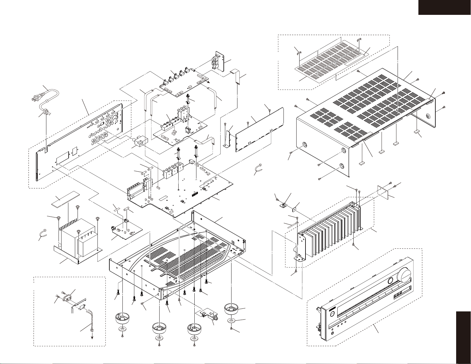
HT-R391
EXPLODED VIEWS-1
OVERALL
P901
Refer to
EXPLODED VIEWS-2
A056
U0014
F901E
U010
F6901
F6902
P8002
U0050
P8002
P2001
U0042
A021
x 2 pcs.
A017
To U0010
P101
U0011
P2800
A071
U0010
P8001
A073
x 3 pcs.
U0020
A254
x 6 pcs.
A354
x 6 pcs.
MMQ only
A342
x 9 pcs.
A054
U0012
A350
U0013
A040
x 2 pcs.
A360
A340
A360
A270
x 4 pcs.
A362
MDC only
A042
x 2 pcs.
U0015
A025
x 4 pcs.
A060
x 2 pcs.
MDS only
A110
x 2 pcs.
T901
P907
P901B
To U0014
U0044
A019
A011
F901
A256
A040
A009
x 3 pcs.
A001
A013
x 2 pcs.
A010
U0043
A003
x 4 pcs.
A005
x 4 pcs.
A007
x 4 pcs.
A043
A044
Refer to
EXPLODED VIEWS-2
A038
A038
HT-R391
Refer to
EXPLODED VIEWS-3
Page 24
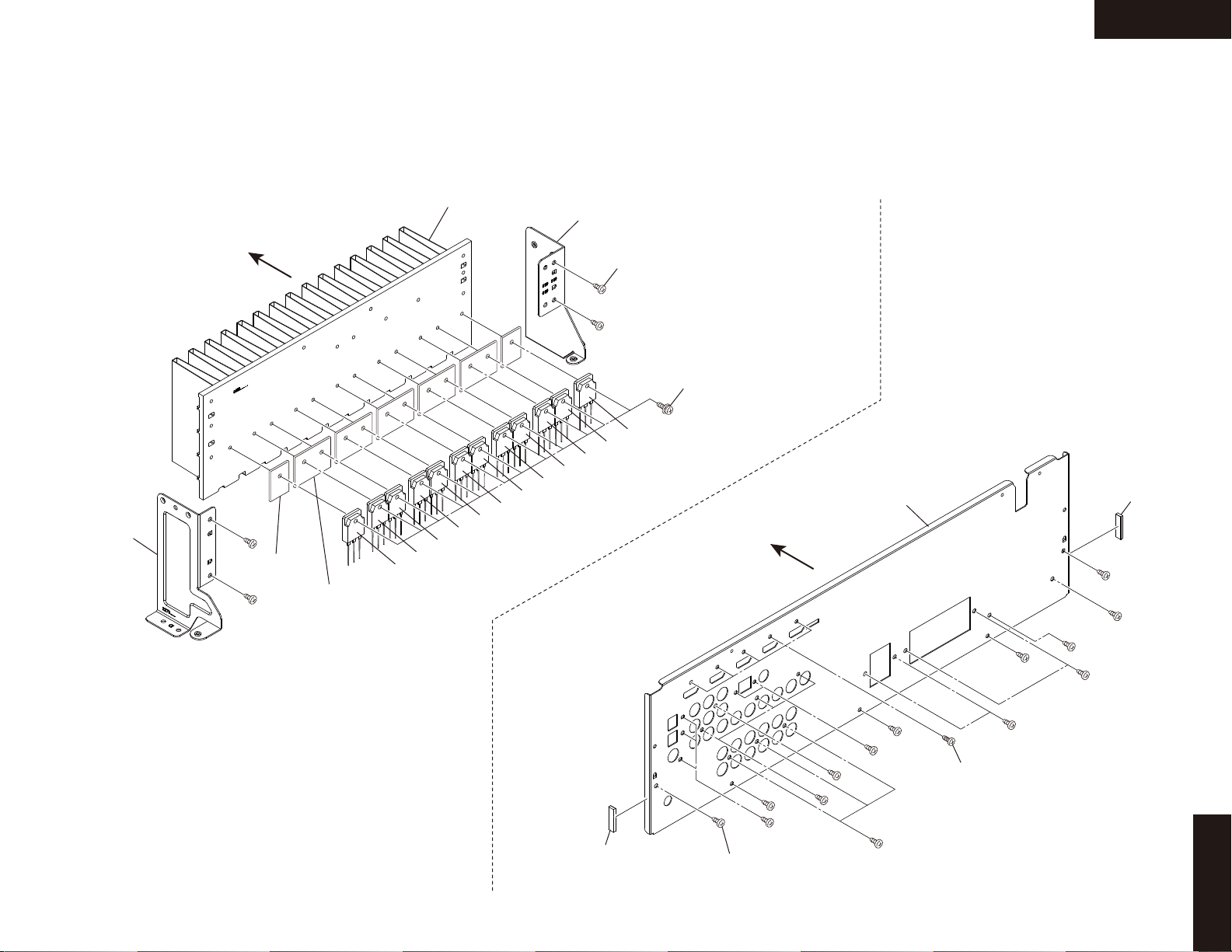
EXPLODED VIEWS-2
HEAT SINK / REAR PANEL SECTION
HEAT SINK SECTION
Front
HT-R391
A030
A032
A036
x 4 pcs.
A050
x 12 pcs.
A034
Q6050A
x 2 pcs.
Q6050B
x 5 pcs.
Q6065
Q6055
Q6064
Q6054
Q6063
Q6053
Q6061
Q6051
Q6060
Q6050
A102
Q6062
Q6052
Front
A105
x 23 pcs.
REAR PANEL SECTION
A101
A103
x 5 pcs.
A102
HT-R391
Page 25
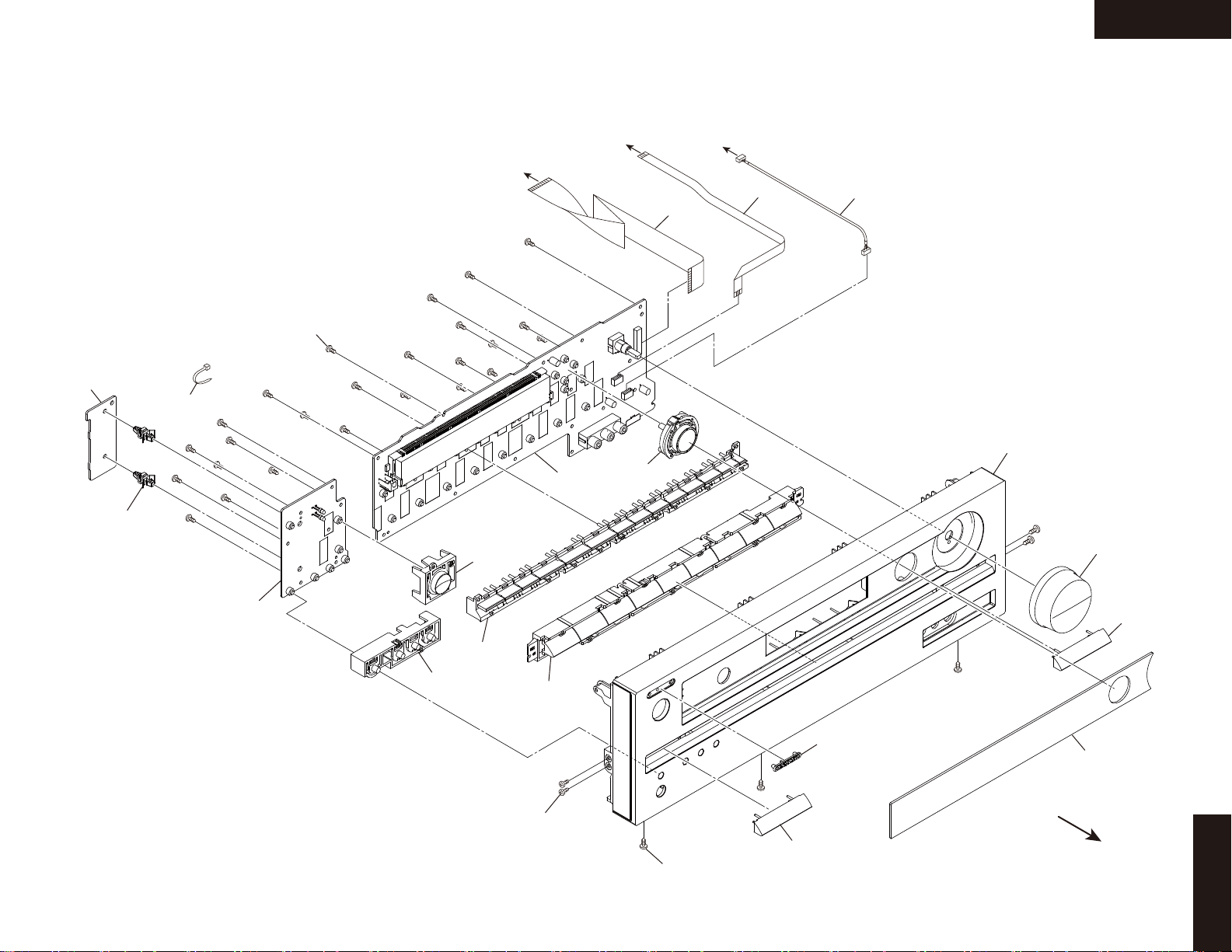
EXPLODED VIEWS-3
FRONT SECTION
To U0020
To U0040
HT-R391
To U0020
U0016
A273
x 2 pcs.
A242
U0041
A225
x 22 pcs.
A217
U0040
A219
P701
P703
P3101
A201
A321
A214
A211
A216
A213
A260
x 4 pcs.
A255
x 3 pcs.
A214
A207
A202
HT-R391
Front
Page 26

TX-SR313/ HT-R358/ 558/ 391/ HT-RC430
A
SCHEMATIC DIAGRAMS-1 (PART-1)
BLOCK DIAGRAM AUDIO SECTION
BADIS-0654 1/4
1
2
3
4
5
(HT-R558 ONLY)
MIC
AUX
TUNER PACK
BAAF-1133 1/2
TV/CD
GAME
CBL/SAT
VCR/DVR OUT
VCR/DVR
BD/DVD
BAAF-1133 2/2
RI
COAX 1
OPT1
OPT2
BAHDM-0678
Q8101
AVD7623
OUTIN4
HDMI Tx
HDMI Rx
IN1
Q201
DA808
DSP
MIC AMP
MIC DET
RI
INTERFACE
HDMI (REPEATER)
TRANSCEIVER
X8100-XTAL
28.6363MHz
HDMI MCK
HDMI BCK
HDMI LRCK
HDMI FLR
HDMI SPDIF
SPDIF
X201-XTAL
24.000MHz
DIR BCK
DIR LRCK
DIR FLR
DIR MCK
DSP SBLR
(BL/BR)
(CT/SW)
DSP CSW
DSP SLR
(SL/SR)
(FL/FR)
DSP FLR
CX LRCK
CX SCLK
DATA+
DATAVBUS
USB EN VBUS
OVERCURRENT DET
SP to MiCOM
SPI
B C D E F G H
BADIS-0654 2/4
FL
23
24
21
20
17
18
11
12
9
8
15
14
5
(SBR)
6
3
2
(FR)
(FL)
SBL
(SR)
SBR
(SL)
SW
SR
(SBL)
FR
CEN
Subwoofer
AV=+15dB
SL
POWER AMPLIFIER
+29dB
+29dB
+29dB
+29dB
+29dB
+29dB
Z2MUTE
RI
AMUT
SPEAKER TERMINALS
(TX-SR313/HT-R558/HT-RC430 ONLY)
SPRLB_SPB
SPRLCS
SPRLF
SURR R
SURR L
ZONE2 R
ZONE2 L
U PORT R
U PORT L
(HT-R391/HT-R358 ONLY)
SPKR B
SPKR B
SW-PREOUT
(HT-R358 ONLY)
UPORT OPTION UNIT
UNIVERSAL PORT
P2081
UPORT
BADIS-0654 3/4
+6dB
LPF
+-
PCM1681
8ch DAC
Q351
+6dB
LPF
+-
+6dB
LPF
+-
+6dB
LPF
- ++-
OVERCURRENT DET
VMCLK
(HDMI SLC)
VMSDO
(HDMI SDA)
DIG CLK
DIG SDO
VMSDI
DIGSDI
DIGSDO
DIGCLK
SPI
uPD70F3746
XOUT
X501-XTAL
5MHz
Q701
MICOM
XIN
USB EN VBUS
SDI
SDO
CLK
USB VBUS
HI SIDE SW
SPI
DATA+
DATAVBUS
+5V
(TX-SR313/HT-R391/HT-R558/
BADIS-0654 4/4
FLDCLK
FLDSDO
FRONT
SDI
SDO
CLK
MODEL NO. TX-SR313/HT-R391/HT-R358/HT-R558/HT-RC430
BLOCK DIAGRAM (PART-1) AUDIO SECTION
2011.12.26
COAX1
OPT1
OPT2
(BL/BR)
(CT/SW)
(SL/SR)
(FL/FR)
85
86
81
82
73
72
78
79
70
71
68
66
67
69
64
65
62
63
60
61
58
59
90
91
75
76
84
83
MAIN L
MAIN R
SUB L
REC L
REC R
54
55
47
46
RTAD
LTAD
COAX1
OPT1
OPT2
HDMI SPDIF
HDMI MCK
HDMI BCK
HDMI LRCK
HDMI FLR
Z2 L
Z2 R
Q4001
R2A15218FP
Downmix
FL/FR -12dB
SW -1.5dB
PCM9211
Q4003
2ch ADC
DIR
Q301
TONE
(FR)
94
FL
INVERTING
43
93
(FL)
INVERTING
42
FR
95
CEN
38
98
41
97
40
SW
96
39
100
SL
(SBR)
37
99
SR
(SBL)
36
44
45
*NOTICE
1.Actually the right and left in/output signal of Q4001(R2A1518FP) is connected reversely to real signal.
ex)(FR)<--->FL ,(FL)<--->FR
2.SL & SR in/out siganl of Q4001 is actually connected to SBL & SBR in/out(preout) signal.
(SL<--->SBL, SR<--->SBR)
3.SBL & SBR in/out siganl of Q4001 is actually connected to SL & SR in/out(spk out) signal.
(SBL<--->SL, SBR<--->SR)
SL
SR
SW
C
FL
FR
DIR MCK
CX LRCK
CX SCLK
DSP SBLR
DSP SLR
DIG CLK
DIG SDO
DIG SDI
DIR BCK
DIR LRCK
DIR FLR
DIR MCK
X-TO
X-Tl
MCLK
DSP CSW
DSP FLR
X301-XTAL
24.576MHz
TONE
+6dB
LPF
(BL/BR)
(SL/SR)
(CT/SW)
(FL/FR)
SPI
+6dB
LPF
+-
P7201
HEADPHONES
FRONT LEFT
FRONT RIGHT
CENTER
SURR. LEFT
SURR. RIGHT
SUBWOOFER
LEFT
RIGHT
P7501
USB
YKF45-0029N
HT-RC430 ONLY)
Q7003
M66005
Q153
EEPROM
Page 27

TX-SR313/ HT-R358/ 558/ 391/ HT-RC430
A
SCHEMATIC DIAGRAMS-2 (PART-2)
BLOCK DIAGRAM VIDEO SECTION
NO USE
1
7
14
6
13
12
5
4
11
10
3
9
2
1
8
7
14
6
13
12
5
4
11
10
3
9
2
1
8
2
D4 VIDEO INPUT
Y1
B C D E F G H
CEC
TMDS
TMDS
CEC
TC74HC4053
INH
CEC
DDC
HDMI IN4 Rx Port A
HDMI IN3
HDMI IN2
A
B
HDMI IN1
DDC
+5V
HP DET
TMDS
CEC
DDC
+5V
HP DET
TMDS
CEC
DDC
+5V
HP DET
TMDS
CEC
DDC
+5V
HP DET
RPWR
HPD
TMDS
CEC
DDC
RPWR
HPD
TMDS
CEC
DDC
RPWR
HPD
TMDS
CEC
DDC
RPWR
HPD
Rx Port B Tx
Q8101
ADV7623
HDMI 4Rx Tx
Rx Port C
Rx Port D
I2S
ARC S/PDIF
I2S
S/PDIF
S/PDIF
I2C
TMDS
DDC
HPD
+5V Hot Plug
TMDS
CEC
DDC
+5V
HP DET
HDMI OUT
CB1
ISO
NJM1328
PY
PB
PR
CV
6dB
6dB
6dB
6dB
DRV
DRV
DRV
DRV
DRV
I2C
MUTE
1
8
2
9
3
10
11
4
5
6
7
D4 OUT
12
13
14
Y
COMPONENT
OUT
CB
CR
MONITOR
VCR/DVR
COMPOSITE VIDEO OUTPUT
CR1
3
Y2
CB2
Yin1
Yin2
Yin3
CR2
COMPONENT VIDEO INPUT
4
DVD
PBin1
PBin2
PBin3
PRin1
PRin2
PRin3
VCR/DVR
CBL/SAT
GAME/TV
AUX1
(FRONT)
Vin2
Vin3
Vin4
Vin5
Vin1
Vin6
Vin7
COMPOSITE VIDEO INPUT
5
UPort
ISOOUT
ISOIN
Model No. TX-SR313/HT-R391/HT-R358/HT-R558/HT-R591/HT-RC430
SCHEMATIC DIAGRAM (PART-2) BLOCK DIAGRAM(VIDEO)
28-12-2011
Page 28

TX-SR313/ HT-R358/ 391/ 558/ 591/ HT-RC430
A
B C D E F G H
SCHEMATIC DIAGRAMS-3 (PART-3)
BLOCK DIAGRAM DIGITAL AUDIO SECTION
1
S/PDIF
INPUT
XTAL
24.576MHz
2
Q301
4
39
DIR
4
MPIO_A1
XTI
DIVIDE
PCM9211
DIR/ADC
DIR
AUXIN1
ADC
ANALOG
A
D
C
DOMAIN
Q302
PCM1681
15
16
MPO0
MPO1
256x48K
MPIO_B0
MPIO_B1
11
12
MPIO_B2
MPIO_B3
13
14
MPIO_CMPIO_B
MPIO_C1
MPIO_C0
9
8
7
MPIO_C2
MPIO_C3
10
MAIN OUT
BCK18LRCK17DOUT
SCKO
19
20
DAC
BCK
SCK
5
7
LRCK6DATA1
8
12
DATA213DATA4
DATA3
11
XTAL
11.2896MHz
256x44.1K
No USE
HDMI_FLR
HDMI_BCK
HDMI_MCK
HDMI_LRCK
DIR_LRCK
DIR_MCK
DIR_BCK
DIR_FLR
DIR_MCK
CX_LRCK
CX_SCLK
DSP_CSW
DSP_SLR
DSP_FLR
DSP_SBLR
Q201
3
DA808
DSP
DIR_MCK
Q8101
MCLK_IN
SCLK_IN
AP5_IN
AP1_IN
68
69
70
76
CX_SCLK
CX_LRCK
DSP_FLR
HDMI Tx
HDMI Rx
4
MCLK_OUT
SCLK_OUT
AP5_OUT
AP1_OUT
AP2_OUT
AP3_OUT
AP4_OUT
AP0_OUT
5
USB
HDMI_MCK
96
HDMI_BCK
95
HDMI_LRCK
94
HDMI_FLR
88
HDMI_SLR
89
HDMI_CSW
90
HDMI_SBLR
91
HDMI_SPDIF
87
HDMI_SPDIF
DIR_MCK
CX_SCLK
CX_LRCK
DSP_FLR
DSP_SLR
DSP_CSW
DSP_SBLR
DIR_MCK
DIR_BCK
DIR_LRCK
DIR_FLR
HDMI_LRCK
HDMI_SLR
HDMI_CSW
HDMI_SBLR
HDMI_SPDIF
USB DATA
160
AHCLKX1/EPWM0B/GP3[14]
126
ACLKX0/ECAP0/APWM0/GP2[12]
127
AFSX0/GP2[13]/BOOT[10]
111
AXR0[0]/AFSR2/GP3[0]
112
AXR0[1]/ACLKX2/GP3[1]
113
AXR0[2]/AXR2[3]/GP3[2]
115
AXR0[3]/AXR2[2]/GP3[3]
125
AHCLKX0/AHCLKX2/USB_REFCLKIN/GP2[11]
130
ACLKR0/ECAP1/APWM1/GP2[15]
131
AFSR0/GP3[12]
116
AXR0[4]/GP3[4]
121
AXR0[8]/GP3[8]
117
AXR0[5]/AFSX2/GP3[5]
118
AXR0[6]/ACLKR2/GP3[6]
122
UART1_RXD/AXR0[9]/GP3[9]
22
EMA_OE/UHPI_HDS1/AXR0[13]/GP2[7]
123
UART1_TXD/AXR0[10]/GP3[10]
124
AXR0[11]/AXR2[0]/GP3[11]
137
USB0_DP
138
USB0_DM
HDMI Input S/PDIF & Analog
I2S DSD HBR
I2S0 I2S0
I2S1
I2S2
I2S3
Master Clock
Bit Clock
N/A LR Clock
LR ClockLR Clock
DSD0B
HBR1st
DSD2B
DSD1A
DSD1B
DSD2A
DSD0A
N/AN/A
HBR2nd
HBR3rd
HBR4th
N/AN/A
Input
N/A
Model No. TX-SR313/ HT-R391/ HT-R358/ HT-R558/ HT-RC430/ HT-R591 SCHEMATIC DIAGRAM
(PART-3) BLOCK DIAGRAM (DIGITAL AUDIO)
28-12-2011
Page 29

TX-SR313/ HT-R358/ 558/ 391/ HT-RC430
SCHEMATIC DIAGRAMS-4 (PART-4)
ASP SECTION
TX-SR313/ HT-R358/ 558/ 391/ HT-RC430
DMIXL
DMIXR
VOLDATA
IPROTECT
SEC1H
VOLH
SPRLCS
HPDET
SEC1OFF
SPRLF
SPRLB
LTAD
U_PORT_R
U_PORT_L
+22V
S1L+
S1L-
AMUTE
MICMUT
TU_GPIO2
TU_RST
TU_SDA
TU_SCL
TU_RI
TU_LI
+5VTU
MICMUT
VOLH
SL+
SR+
HP_GND
C+
IPROTECT
SW+
PROTECT
FL+
RI
FR+
GND_LPF
LTAD
RTAD
TU_RST
TU_SDA
TU_GPIO2
HP_GND
FL+
SW+
C+
SR+
SL+
FR+
GND_LPF
TU_SCL
RTAD
RI
DAC_CT
DAC_SW
DAC_SR
DAC_SL
DAC_FL
DAC_FR
HPDET
PROTECT
DAC_FL
DAC_SW
GND_M
GND_AMP
GND_DG
COAX1
+3.3V
OPT2
GND_CH
OPT1
-12V
+12V
-12V
MICMUT
+12V
AUX_R
MICOUT
AUX_L
SPRLCS
VOLCLK
SEC1OFF
AMUTE
SPRLF
VOLDATA
SEC1H
SPRLB
SL_IN
SR_IN
Z2R
Z2L
DAC_FR
VOLCLK
SW_IN
SR_IN
SL_IN
R_IN
L_IN
C_IN
VCR/DVR
Rch
Lch
OUT
Lch
GAME
Rch
Lch
Rch
Downmix
FL/FR: -12dB
(MULTI FR IN)
(MULTI FL IN)
(MULTI C IN)
(MULTI SW IN)
Lch
(MULTI FL)
Rch
(MULTI FR)
DVD/BD
Rch
Lch
VCR/DVR
Rch
(MULTI SW)
Lch
(MULTI C)
CBL/SAT
*FL/FR use DVD IN
*C use CBL Lch IN
*SW use CBL Rch IN
Multi ch in for AMP TEST
Multi ch in for AMP TEST
TUNER
GAME
CD/TV
CBL/SAT
VCR/DVR
DVD/BD
SW: +3.5dB
FR
FL
C
FR_OUT
FL_OUT
C_OUT
SR
SL
SL_OUT
SR_OUT
Subwoofer
*
SW
*
AUX_L
RTAD
LTAD
SL SW C FR FL
SW_OUT
AUX_R
GND_LPF
+12V
-12V
TU_L
N.M
CD/TV
RI IN
FL
FR
NOT USE
*
NOT USE
NOT USE
TULI
TURI
TU_R
+5V TU
TU_R
TU_L
N.M
(MULTI SR IN)
(MULTI SL IN)
(MULTI SR)
(MULTI SL)
NOT USE
NOT USE
*SL/SR use GAME IN
GND_LPF
NC
N.M
AGND
SW PRE OUT
AGND
AGND
SW preout
*OPTION
+20dB
N.M
AGND
SR
FL
FR
C
SW
SL
SR
GNDA_AUX
GND
GNDTU
Surr_GND
Z2_GND
NC
UTSP
OPT1
COAX1
UTSP
OPT2
+12V
NM
NM
102J
4.7(1W) - T3/H3
6.8V
-6.8V
23.4V
22.1V
-23.1V
-23.7V
11.8V
-11.7V
11.7V
-11.9V
11.9V
5.6V
11.6V
GND_LPF
+12V
-12V
-11.8V
H39/H35
MDC
MPA
MPP
MMQ
MMR
MMK
MDS
MDC MPP
MPB MMK
MMQ
R4001
R4107
47uF/50V 2.2uF/50V
2.2K220K
10(1W) 4.7(1W) 4.7(1W)10(1W)
T3/H55/H43
Option table
-2A -2B -2C -2D -2F -2E
HT-R391 DC,DS,MQ,MK
HT-R358 PP,PBH35
H39
T3
H55
H43
C4107
Table: B
Table: A
TX-SR313 DC,DS,PP,PA,MQ,MR,MK
HT-R558 PP,PA,MQ,MR
HT-RC430 DC
MDS
A
B
VIDEO
Surr_L
Surr_R
B
VIDEO
1mm FFC CABLE
DISPLAY
FROM TUNER PACK
TUNER FFC CABLE(1.25mm)
TUNER PACK
1mm FFC CABLE
HDMI
1mm FFC CABLE
HDMI
HDMI
Model No. TX-SR313/HT-R391/HT-R358/HT-R558/HT-RC430
SCHEMATIC DIAGRAM (PART-4) ASP SECTION
2011.12.26
TO BAHDM-0678(PART-18) TO BAHDM-0678(PART-14)
FROM BAHDM-0678(PART-18)
FROM BADIS-0654(PART-10)
TO BAVD-0656(PART-8)
TO BAVD-0656(PART-8)
ASP
BAAF-1133 (1/2)
CLAMP
FOR P703
BAAF-1134
DIGITAL IN
FROM AMP SECTION
(PART-5)
TO AMP SECTION
(PART-5)
TO AMP SECTION
(PART-5)
C4204
102J
R4194
220K
C4065 474J
C4066 823J
C4067 223J
C4063
823J
C4064
223J
C4013
221J
C4008
221J
R4008
330
R4047
100K
R4048
100K
R4060
100K
R4059
100K
R4058
100K
R4057
100K
R4054
100K
R4053
100K
R4020
330
R4019
330
R4018
330
R4017
330
R4016
2.2K
R4015
2.2K
R4014
330
R4013
330
C4205
102J
C4018
221J
C4017
221J
R4056
220K
R4055
220K
C4014
221J
R4091
22K
R4098
12K
R4090
12K
R4095
10K
R4193
220K
R4082
100K
R4089
0
R4085
1.8K
Q4003A
NJM4580
1
2
3
4
Q4003B
NJM4580
7
8
6
5
C4210
47/25
C4209
47/25
R4094
10K
R4007
330
R4092
330
R4093
3.3K
R4096
330
R4097
3.3K
C4091 101J
C4090 101J
C4007
221J
R4174
(1W)
68
R4099
22K
C4086
47/25
C4085
47/25
R4192
220K
R4068
100K
Q4102
RN1441
R4102
220K
C4100
47/50
R4100
220K
R4110
2.2K
Q4100
RN1441
R4111
2.2K
R4101
220K
C4101
47/50
R4112
2.2K
R4103
220K
R4104
220K
C4103
47/50
C4104
47/50
Q4104
RN1441
Q4103
RN1441
R4113
2.2K
R4114
2.2K
C4102
47/50
C4037
221J
R4027
22K
R4107
VAL
R4117
270
Q4117
RN1441
R4127
100
Q4107
RN1441
R4181
220K
C4107
VAL
C4132
103J
R4130
220
R4134
10K
C4130
47/50
R4175
(1W)
68
Q4101
RN1441
C4131
221J
R4133
1.2K
R4132
15K
R4131
47K
R4004
330
R4003
330
R4043
100K
R4044
100K
Q4130B
NJM4580
5
6
8
7
R4080
100K
R4081
100K
C4407
47/25
C4406
47/25
R4079
47K
R4069
220K
R4177
(1W)
15
R4176
1(W)
15
Q4142B
NJM4580
1
3
2
Q4142A
NJM4580
4
7
8
6
5
Q4140B
NJM4580
1
3
2
Q4140A
NJM4580
4
7
8
6
5
P4005
7
2
1
3
5
4
6
C4166
220/25
R4078
47K
JL502A
1
234
5
R4408
330
C4405
47/25
R4404
22K
R4410
100K
C4402
47/25
C4417
101J
R4406
27K
C4002
152J
C4001
152J
R4000
330
L4001
LBC2518T2R2M
R4067
100K
R4088
2.2K
R4087
2.2K
C4173
220/25
C4172
220/25
C4170
1/50
C4171
1/50
C4301
1000/35
R4161
(1W)
0.22
R4160
(1W)
0.22
C4300
334J
C4302
470/35
J6501
R4006
(1W)
15
R4005
(1W)
15
R4002
1(W)
NC
R4001
(1W)
10
Q4170
78M12
3
O
2
G
1
I
Q4171
79M12
3
O2I
1
G
J6500
Q4400B
NJM4580M
5
6
8
7
R4401
22K
R4409
330
C4404
47/25
R4400 22K
C4414
105Z
R4411
100K
C4403
47/25
C4416
101J
R4407
27K
R4405
22K
C4412
105Z
C4415
105Z
C4413
105Z
R4419
0
C4408
104Z
D4218
NC
D4208
NC
D4301
RL1N4003
D4300
RL1N4003
D4302
RL1N4003
D4303
RL1N4003
R4420
4.7K
R4440
330
R4421
4.7K
R4422
4.7K
R4442
330
R4427
4.7K
R4447
330
R4423
4.7K
R4443
330
R4430
15K
R4450
560
C4430
151J
R4441
330
R4431
15K
R4451
560
C4431
151J
R4432
15K
R4452
560
C4432
151J
R4437
15K
R4457
560
R4433
15K
R4453
560
C4433
151J
R4424
4.7K
R4023
0
C4409
104Z
R4412
22
R4413
22
R4166
22
R4086
1.8K
Q4400A
NJM4580M
3
2
1
4
P101BNSCT-9P2102
9
8
7
6
5
4
3
2
1
P8001A NSCT-21P2412
1
2
3
4
567
8
9
10
11
12
13
14
15
161718
192021
R4201
22
R4200
22
C4186
470/16
C4187
470/16
P4000
C4208103K
JL503A
1
2
3
4
5
6
7
P4009
2
3
1
JL504A
1
2
3
R4029
100
P4100B
1
Q4130A
NJM4580
3
2
1
4
C4423
332J
C4422
332J
C4421
332J
C4420
332J
C4437
102J
C4427
333J
P4100A
1
J4610
Q4143B
NJM4580
1
3
2
Q4143A
NJM4580
4
7
8
6
5
R4434
15K
R4454
560
R4444
330
C4434
151J
C4424
332J
C4110
220/25
C4111
220/25
C4072
47/50
C4077
47/50
C4073
47/50
C4074
47/50
C4070
47/50
C4071
47/50
P4006
7
2
1
3
5
4
6
C4062
474J
C4057
47/25
C4052
47/25
C4051
47/25
C4053
47/25
C4054
47/25
C4050
47/25
TP4065
TP4064
TP4080
TP4077
TP4098
TP4000
TP101
TP8002
TP4074
TP4072
TP4073
TP4084
TP4083
TP4087
TP4092
TP4097
TP4091
TP4090
TP4089
TP4088
TP4011
TP4013
TP4008
TP4009
TP4012
TP4001
TP4025
TP4057
C4060
47/50
C4061
47/50
TP4053
TP4031
Q4001
R2A15218FP
80
N.C.
79
IN-L9
78
IN-R9
77
N.C.
76
INLA/RECL1
75
INRA/RECR1
74
N.C.
73
IN-L8
72
IN-R8
71
IN-L7
70
IN-R7
69
IN-L6
68
IN-R6
67
IN-L5
66
IN-R5
65
IN-L4
64
IN-R4
63
IN-L3
62
IN-R3
61
IN-L2
60
IN-R2
59
IN-L1
58
IN-R1
57
N.C.
56
AGND
55
ADCR
54
ADCL
53
N.C.
52
AVEE
51
MUTE
50
CLOCK
49
DATA
48
DGND
47
SUBR
46
SUBL
45
SBLC-IN
44
SBRC-IN
43
FR-IN242FL-IN241SR-IN240SL-IN2
39
SW-IN2
38
C-IN2
37
SBR-IN2
36
SBL-IN2
35
N.C.
34
TRER
33
BASS-R232BASS-R1
31
N.C.
30
AVCC
29
N.C.
28
TREL
27
BASS-L2
26
BASS_L1
25
N.C.
24
FRC
23
FR-OUT
22
AGND
21
FL-OUT
20
FLC
19
AGND
18
CC
17
C-OUT
16
AGND
15
SW-OUT
14
SWC
13
N.C.
12
SRC
11
SR-OUT
10
AGND
9
SL-OUT
8
SLC
7
AGND
6
SBRC
5
SBR-OUT
4
AGND
3
SBL-OUT
2
SBLC
1
N.C.
100
SBR-IN1
99
SBL-IN1
98
SR-IN1
97
SL-IN1
96
SW-IN1
95
C-IN1
94
FR-IN1
93
FL-IN1
92
N.C.
91
RECL3
90
RECR3
89
N.C.
88
N.C.
87
N.C.
86
INL11/RECL5
85
INR11/RECR5
84
INL10/RECL4
83
INR10/RECR4
82
INLB/RECL2
81
INRB/RECR2
(Botom view)
TP4029
TP4035
L135
BK1608HS102-T
L134
LBC2518T470M
C139
220/10
C140
104Z
Q131
74HCU04F
7
GND
6
5
4
3
2
1 14
VCC
13
IN6
12
OUT6
11
IN5
10
OUT5
9
IN4
8
OUT4
R139
82K
R137
10K
C135080D
C145
220/10
C141
104Z
C143
330J
U131
2
GND
3
VCC
1
IN
L131
LBC2518T2R2M
D131
KDS4148U
C144
330J
R142
47
L133
LBC2518T470M
U132
2
GND
3
VCC
1
IN
R141
47
C131
101J
D132
KDS4148U
C133
104K
R133
10
R131
75
C142
104Z
C130
104Z
R4417
33K
Q4401
2SC2235-Y
R4416
470
R4601
470
R4414
22
R4415
22
R4189
47K
R4190
47K
R4403 33K
R4402
33K
C4003
221J
C4004
221J
C4019
221J
C4020
221J
C4410
681J
C4411
681J
C4015
NM
C4016
NM
R135
NM
P131
3
2
1
P703B NSCT-7P2398
1
2
3
4
5
6
7
R4418
NM
C4024
D4171
HZS7B1
D4172
HZS7B1
D4400
DZ2J056M0L
J4388
J4600
C4203 NM
D4305
KDS4148U
D4304
KDS4148U
P8002A
1
2
3
4
5
678
9
P8003B
7
6
5
4
3
2
1
R4614
2.2K
R4613
2.2K
R4611
220K
R4612
220K
Q4411
RN1441
Q4412
RN1441
R4167
22
C4167
220/25
P4002
7
2
1
3
5
4
6
J410A
1
J411A
1
J401B
1
J410B
1
J411B
1
J401A
1
C4439
10/16
C4440
10/16
TP6100
P6107
U0010
AUDIO PC BOARD
U0011
TERMINAL(DIGITAL) PC BOARD
A
1
2
3
4
5
B C D E F G H
6
7
8
I
J K
Page 30

TX-SR313/ HT-R358/ 558/ 391/ HT-RC430
SCHEMATIC DIAGRAMS-5 (PART-5)
AMP. SECTION
TX-SR313/ HT-R358/ 558/ 391/ HT-RC430
SEC1H
VOLH
IPROTECT
VPRO
IPRO
VOLH
VOLH
VPRO
+BSL2
-BSL2
+BSL
TRIMSL
VPRO
VOLH
VOLH
VPRO
+B1SBL
TRIMSBL
-BSBL2
+BSBL2
+BSBL
TRIMSR
-BSR2
+BSR2
+BSR
SR_IN
SL_IN
VPRO
VOLH
-B1R
+B1R
+BR
+BR2
-BR2
TRIMR
VOLH
VPRO
-B1L
+B1C
-B1C
TRIML
-BL2
+BL2
+BL
+B1L
L_IN
VPRO
VOLH
C_IN
L_IN
SL_IN
+22V
NFSR
GND_AMP
SPSW
SPSL
SPL
SPC
SPR
SPSR
SR_IN
SW_IN
SW_IN
PROTECT
R_IN
R_IN
S1_GND
SEC1OFF
GND_AMP
SEC1OFF
S1L+
S1H-
S1H+
SPRLCS
SPRLF
SPRLB
GND_M
HP_GND
HPDET
SLG
FLG
CG
FRG
SRG
SWG
HP_GND
HPDET
FLG
HPR
HPL
S1L-
S1L+
TRIMC
-BC2
+BC2
+BC
C_IN
NFR
NFSL
NFSBL
NFL
-B1H_B
+B1H_B
NFC
S1L-
+B1SR
+B1SL
-B1SBL
-B1SR
-B1SL
+3.3VMPU
FLAC1
-VP
FLAC2
+3.3VMPU
+3.3VMPU
THERMAL
GNDDG2
SEC2_1
SEC2_2
SEC3_2
SEC3_1
FLAC1
+22V
125V
-B+B
2SC4468
2SA1695
-56.2V
+56.2V
0.6V
1V
-0.3V
AV=29dB
(NH)
ID-
ID+
3
SL
ID+
ID-
(NH)
AV=29dB
1V
-0.3V
0.6V
+56.2V
-56.2V
2SA1695
2SC4468
5
ID+
ID-
(NH)
AV=29dB
1V
-0.3V
0.6V
+56.2V
-56.2V
2SA1695
2SC4468
4
SR
GND_SL
GND_SR
2SC4468
-56.2V
+56.2V
0.6V
-0.3V
1V
AV=29dB
(NH)
ID-
ID+
1
R
GND_R
ID+
ID-
(NH)
1V
-0.3V
0.6V
AV=29dB
+56.2V
-56.2V
2SA1695
2SC4468
0
L
GND_L
(NH)
ID-
ID+
AV=29dB
1V
-0.3V
0.6V
+56.2V
-56.2V
2SC4468
2
C
CND_C
-0.6V
-0.6V
-0.6V -0.6V
-0.6V
-0.6V
2SA1695
2SA1695
F6901
8A
SW
SWG
SRGCGSLG
FRG
FLG
FR(SPB)
Speaker B
output
Speaker output
GND_SW
L
R
SPRLF
SW
C/SL/SR
SP-B
SL/SR/C
FL/FR/SW
SPB L/R
FL/R/SW
L(SPB)
R(SPB)
SR
SL
C
FOR P6402
(WHI)
HOLDER
CLAMP
P6401,P6402 P6400
(BLK)
CLAMP
(RED/WHI)
FOR P6401
(RED)
FOR P6401
(RED)
SPRLCS
SPRLCS
SPRLB_SPB
SPRLF
125V
8A
F6902
FROM BAETC-1137(PART-4)
DISPLAY
CLASS-A
FROM BACLA-1130(PART-6)
CLASS-A
FROM BACLA-1130(PART-6)
CLASS-A
FROM BACLA-1130(PART-6)
CLASS-A
FROM BACLA-1130(PART-6)
CLASS-A
FROM BACLA-1130(PART-6)
CLASS-A
FROM BACLA-1130(PART-6)
PCB HOLD
LR
(PART-4)
FL(SPB)
NM
A
A
A
A
B
B
C
B
B
B
*
*
*
*
HOLDER HOLDERHOLDER
(RED)
(WHI)
(RED)
FROM BADIS-0654(PART-10)
(WHI)
FROM BADIS-0654(PART-10)
FROM BAETC-1137(PART-5)
DISPLAY
FLAC1
FLAC2
SEC3_1
SEC3_2
N.M
N.M
BAETC-1140
-VP
HDMI
TO BAHDM-0678(PART-14)
NM
THERMAL
BAETC-1135
N.C
NC
P6900B(BLK)
TO BAVD-0656
(PART-8)
TO BAETC-1140
(PART-5)
TO BAAF-1133
(PART-5)
VIDEO
BAETC-1137
SEC2/3
HT-R391 DC,DS,MQ,MK
HT-R358 PP,PB
H35
H39
T3
H55
H43
TX-SR313 DC,DS,PP,PA,MQ,MR,MK
HT-RC430 DC
HT-R558 PP,PA,MQ,MR
T3/H55 -2B, H35 -2F
T3 -2C, H39 -2E
MODEL
T3/H43 -2A, H39 -2D
NPT-1603D
NPT-1603P
NPT-1603M
Power Trans
Table: A
Table: B
T3/H55/H43 H39/H35
MDC
MPA
MPP
MMQ
MMR
MMK
MDS
MDC MPP
MPB MMK
MMQ
-2A -2B -2C -2D -2F -2E
63V
8200u
63V
8200u
56V
8200u8200u
56V
Table: C
JUMPER
JUMPER
R6430,R6431
R6432,R6433
R6434
JUMPER
L6004
L6002,L6003
L6000,L6001
C6402
C6401
P6001
R6434
L6004
J6477
NTM-10PDML NTM-12PDML
Destination table
MDS
EX)030:3pF 330:33pF 331:330pF 333:0.033uF
)ARE IN uF/WV.
+
ELECTROLYTIC CAPACITORS(
CIRCUIT IS SUBJECT TO CHANGE FOR IMPROVEMENT.
ARE CRITICAL FOR SAFETY.
Notes
REPLACE ONLY WITH PART NUMBER SPECIFIED.
THE COMPONENTS IDENTIFIED BY MARK
VOLTAGE(MEASUREDWITHVOLTMETER) IS DCVOLTAGE
(NO INPUT SIGNAL in HT-R340MPP)
ALL CAPACITORS ARE IN pF/50WV UNLESS OTHERWISE NOTED.
CAUTION
FOR CONTINUED PROTECTION
RATING REFER TO THE MAKING ADJACENT TO THE SYMBOL.
CE SYMBOLE INDIQUE QUE LE FUSIBLE UTLISE EST
A LENT, E POUR UNE PROTECTION PERMANENTE,N'UTILISER
QUE DES FUSIBLES DE MEME TYPE. CE DARNIER EST
INDIQUE LA QU LE PRESENT SYMBOL EST APPOSE.
THIS SYMBOL LOCATED NEAR THE FUSE INDICATES
THAT THE FUSE USED IS SLOW OPERATING TYPE
FOR CONTINUED PROTECTION AGAINST FIRE FUSE
HAZARD,REPLACE WITH SAME TYPE FUSE. FOR FUSE
AFIN D'ASSURER UNE PROTECTION
PERMANENTE CONTRE LES RISQUES
D'INCENDIE, REMPLACER UNIQUEMENT
PAR UN FUSIBLE DE MEME TYPE
ET CALIBRATION COMME INDIQUE.
ATTENTIION
AGAINST FIRE HAZARD, REPLACE
ONLY WITH FUSE OF SAME TYPE
AND RATING INDICATED.
A V
A V
From ASP SECTION
From ASP SECTION
To ASP SECTION
(PART-4)
BAAF-1133 (2/2) AMP
(PART-4)
SPSLE
SPLE
SPCE
SPRE
SPSRE
SPSBRE
SPSBLE(SW)
GNDRL
2.0mm JUMPER LEAD
P6402B
#18
1
R6455
10K
C6455
104Z
Q6454
2SA1163-BL
R6460
47K
R6456
22K
C6454
1/50
R6457
22K
R6452
10K
C6452
104Z
Q6453
2SA1163-BL
R6454
47K
R6451
33K
D6452
KDS4148U
D6451
KDS4148U
C6451
100/25
C6453
1/50
D6453
NM
R6453
22K
C6456
10/50
D6455
UDZS3.3B
R6459
5.6K
R6458
5.6K
Q6053
2SC5198
Q6063
2SA1941
R6083
(1/4W)
0.22
R6093
(1/4W)
0.22
Q6073
2SC2229
R6233
470
R6203
5.6K
Q6003
2SC1740S-S
D6003
KDS4148U
C6053
103J
R6153
10K
R6163
33K
R6183
47K
R6173
47K
R6175
47K
R6185
47K
R6165
33K
P6085
NPLG-2P29
1
2
R6145
56K
R6155
10K
C6055
103J
D6005
KDS4148U
Q6005
2SC1740S-S
R6205
5.6K
R6235
470
Q6075
2SC2229
R6095
(1/4W)
0.22
R6085
(1/4W)
0.22
Q6055
2SC5198
R6174
47K
R6184
47K
R6164
33K
P6084
NPLG-2P29
1
2
P6004B
NPLG-9P0964
1
2
3
4
5
6
7
8
9
R6144
56K
R6154
10K
C6054
103J
D6004
KDS4148U
Q6004
2SC1740S-S
R6204
5.6K
R6234
470
Q6074
2SC2229
R6094
(1/4W)
0.22
R6084
(1/4W)
0.22
Q6064
2SA1941
Q6054
2SC5198
TP6102B
P6013B
NPLG-7P0962
1
2
3
4
5
6
7
Q6051
2SC5198
R6081
(1/4W)
0.22
R6091
(1/4W)
0.22
Q6071
2SC2229
R6231
470
R6201
5.6K
Q6001
2SC1740S-S
D6001
KDS4148U
C6051
103J
R6151
10K
R6141
56K
P6081
NPLG-2P29
1
2
R6161
33K
R6181
47K
R6171
47K
R6170
47K
R6180
47K
R6160
33K
R6140
56K
C6050
103J
D6000
KDS4148U
Q6000
2SC1740S-S
R6200
5.6K
R6230
470
Q6070
2SC2229
R6090
(1/4W)
0.22
R6080
(1/4W)
0.22
Q6060
2SA1941
Q6050
2SC5198
R6172
47K
R6182
47K
R6162
33K
P6082
NPLG-2P29
1
2
R6152
10K
C6052
103J
Q6002
2SC1740S-S
D6002
KDS4148U
R6202
5.6K
R6232
470
Q6072
2SC2229
R6092
(1/4W)
0.22
R6082
(1/4W)
0.22
R6142
56K
R6143
56K
R6305
0
Q6065
2SA1941
Q6052
2SC5198
Q6061
2SA1941
Q6062
2SA1941
R6300
0
R6301
0
P6003B
NPLG-3P0958
1
2
3
P6083
NPLG-2P29
1
2
C6251
473J
C6250
473J
C6252
473J
R6441
(1W)
8.2
R6440
(1W)
8.2
R6442
(1W)
8.2
R6432
RS1/2WB-10
10
R6431
RS1/2WB-10
10
R6433
RS1/2WB-10
10
R6434
RS1/2WB-10
10
R6435
RS1/2WB-10
10
P6080
NPLG-2P29
1
2
R6150
10K
C6077
103J
C6074
103J
C6073
103J
C6072
103J
C6070
103J
C6071
103J
C6088
102J
C6089
102J
C6082
102J
C6083
102J
C6087
102J
C6084
102J
C6080
102J
C6081
102J
J6477
R6443
(1W)
8.2
R6444
(1W)
8.2
R6445
(1W)
8.2
R6402
1K
R6412
(1/2W)
0.1
D6403
1SS352
C6417
102J
Q6408
KRC105S
J6406
JM
R6403
47K
J6004
RL641
NRL-1P10A-DC12-196
4
3
5
2
1
RL642
NRL-1P10A-DC12-196
5
3
4
1
2
D6454
NM
D6402
1SS352
C6411
102J
D6052
KDS4148U
D6051
KDS4148U
D6055
KDS4148U
D6057
KDS4148U
D6053
KDS4148U
C6111 102J
C6115 102J
C6117 102J
R4602
0
Q6602
KRC105S
Q6604
KRC105S
Q6601
KRC105S
J6455
TP6301
TP6401
TP6104
P6108 P6106
TP6106
P6101 P6103
TP600
TP6302
C6112 102J
C6113 102J
TP601
C6412
334J/50V
C6413
334J/50V
D6401
D5SBA60
4
2
1
3
Q6407
KTC3875-GR
Q6451
KTC3875-GR
Q6452
KTC3875-GR
C6253
473J
C6254
473J
C6255
473J
JL603B NSCT-9P900
9
8
765
432
1
JL605B
NSCT-5P97
5
4
3
2
1
JL954B
NSCT-9P900
9
8
7
6
5
4
3
2
1
TP954
JL600B NSCT-7P898
7
6
5
4
3
2
1
JL600A NSCT-7P898
1
2
3
4
5
6
7
P6002B
NPLG-9P0964
1
2
3
4
5
6
7
8
9
P6000B
NPLG-9P0964
1
2
3
4
5
6
7
8
9
P6001B
NPLG-9P0964
1
2
3
4
5
6
7
8
9
P6005B
NPLG-9P0964
1
2
3
4
5
6
7
8
9
TP5509
TP5507
P5509A
1234
P5507A
1234
TP6010
P6010A
1234
L6002
SC-0.8X5.5X18.5T
L6001
SC-0.8X5.5X18.5T
L6003
SC-0.8X5.5X18.5T
L6004
SC-0.8X5.5X18.5T
L6005
SC-0.8X5.5X18.5T
R6420
RS1/2WBJ-390
R6421
RS1/2WBJ-390
R6461
10K
RL643
5
2
6 1
3
4
RL660
5
2
6 1
3
4
RL662
5
2
6 1
3
4
RL663
5
2
6 1
3
4
RL667
5
2
6 1
3
4
RL669
5
2
6 1
3
4
L6000
SC-0.8X5.5X18.5T
R6430
RS1/2WB-10
10
C6402
8200/56
+
D966
RL1N4003
P6401A
1
D965
RL1N4003
C6401
8200/56
+
P6400B
1
D6401A
RAD-083
6 5
P6001
NTM-12PDML362
13
12
6
11
5
10
4
9
3
8
2
7
1
14
SL
R
C
SR
SW
L
R6102
0.22(2W)
1
R6100
0.22(2W)
1
R6101
0.22(2W)
1
R6103
0.22(2W)
1
R6104
0.22(2W)
1
R6105
0.22(2W)
1
R6210
3.9K
R6211
3.9K
R6212
3.9K
R6213
3.9K
R6214
3.9K
R6215
3.9K
F6901B1F6901A
F6902B1F6902A
P6102 P6104
P6402A
1
P6401B
#18
1
D960
RL1N4003
JL953B NPLG-5P588
1
2
345
JL951B
NSCT-5P896
543
2
1
R960
8.2(1/2W)
C950
104J
D961
RL1N4003
R950
10(1W)
D962
UDZS22B
D963
UDZS22B
Q960
2SC2235
R962
8.2K
R963
8.2K
C961
47/50
R964
33K
C962
104J
D964
UDZS36B
J950
C963
47/50
R961
3.3
C960
220/63
TP631
C6630
104Z
Q6380
LM61CIZ
1
G
2
O
3
V
JL501A NSCT-3P874
3
2
1
C6631
104Z
Q6380A
1
2
P950
P951
P953
P954
P952
P955
P956
P960
1
P959
1
P961
1
P958
1
P957
1
JL954A
NSCT-9P900
1
2
3
4
5
6
7
8
9
JL952A
NSCT-3P894
1
2
3
JL951A
NSCT-5P896
1
2
3
4
5
P6002
NTM-4PDML364
5
4
2
3
1
6
L
R
JL603ANSCT-9P900
12345
6
7
8
9
Model No. TX-SR313/HT-R391/HT-R358/HT-R558/HT-RC430
SCHEMATIC DIAGRAM (PART-5) AMP SECTION
2011.12.26
U0010 AUDIO PC BOARD
U0012
SENSOR
PC BOARD
U0014
TERMINAL
PC BOARD
U0016
POWER SUPPLY
PC BOARD
A
1
2
3
4
5
B C D E F G H
6
7
8
I
J K
Page 31

TX-SR313/ 414/ 515/ 515AE/ HT-R358/ 391/ 558/ 591/ 758/ 791/ HT-RC430/ 440/ 460/ DTR-20.4
A
SCHEMATIC DIAGRAMS-6 (PART-6)
AMP.(CLASS-A) SECTION
ADJUSTMENT OF IDLING CURRENT
[NOTES]
1. Set R6040
1
2. Equip series 1/4W 100-ohm resisters near the terminal respectively in the each poles of the jig used for
P6080-6086 terminals.
[PROCEDURES]
1. Set the voltages at P6080
no input and no load, immediately after POWER ON.
2. Set the voltages at P6083
no input and no load, immediately after POWER ON.
3. Re-adjust by following procedure after
2
3
4
5
6046 to minimum position before POWER ON.
6082 to 2.5mV by adjusting R6040
6086 to 1.5mV by adjusting R6043
4 6
minutes of heat running.
6042, under the condition of
6046, under the condition of
SL/ SR/ SBL/ SBRL/ C/ R
Below 9mV 9mV Below 6mV 6mV
Between
9
Over 11mV 11mV Over 8mV 8mV
11mV
Leave it as it is. Between
6
8mV
B C D E F G H
54.4V
Leave it as it is.
BACLA-1130
CLASS-A
CODE
MODEL
T3 TX-SR313
H39 HT-R391
H35 HT-R358
H55 HT-R558
H43 HT-RC430
H59 HT-R591
T4
TX-NR414
H75
HT-R758
T5
TX-NR515
H46
HT-RC460
H79
HT-R791
D2
DTR-20.4
1
2
P6010A
3
GND_DecupL
234 1
P5509B
U0020
APLIFIER PC BOARD
FL
1K
100K
R5090
R5110
R5020
330
R5040
2.2K
100K
100K
R5021
330
R5041
2.2K
100K
100K
R5022
330
R5042
2.2K
100K
-48.9V
-48.9V
-48.9V
R5300
R5111
R5301
R5112
R5302
Q5000
22
1K
Q5001
22
1K
Q5002
22
P6000:B
FR
P6001:B
C
P6002:B
C5010
C5000
C5001
C5002
47/50
101J
C5011
47/50
101J
C5012
47/50
101J
R5010
HZS6A3
D5000
R5011
HZS6A3
D5001
R5012
HZS6A3
D5002
-0.2V
120K
C5020
-0.2V
120K
C5021
-0.2V
120K
C5022
R5320
10/50
R5321
10/50
R5322
10/50
120K
R5100
R5091
120K
R5101
R5092
120K
R5102
R5000
7
8
1.5K
R5001
7
8
1.5K
R5002
7
1.5K
8
KTC3201-BL
R5310
4.7K
R5050
Q5050
1.2K
R5060
470
R5080
KTC3201-BL
R5311
4.7K
R5051
Q5051
1.2K
R5061
470
R5081
KTC3201-BL
R5312
4.7K
R5052
Q5052
1.2K
R5062
470
R5082
Q5010
22
2N5551C
Q5011
22
2N5551C
Q5012
KTC3201-BL
22
2N5551C
KTC3201-BL
-0.2V
220/25
C5040
KTC3201-BL
-0.2V
C5041
220/25
-0.2V
C5042
220/25
R5160
C5080
Q5030A
R5170
R5161
C5081
Q5031A
R5171
R5162
C5082
Q5032A
R5172
100
(1/4W)
Q5030
2SA949-Y
040C
Q5040
2SC2229-Y
100
(1/4W)
100
(1/4W)
Q5031
2SA949-Y
040C
Q5041
2SC2229-Y
100
(1/4W)
100
(1/4W)
Q5032
2SA949-Y
040C
Q5042
2SC2229-Y
100
(1/4W)
10
R5183
SL
R5093
C5003
C5004
C5005
C5006
C5013
47/50
101J
C5014
47/50
101J
C5015
47/50
101J
C5016
47/50
101J
R5013
HZS6A3
D5003
R5014
HZS6A3
D5004
R5015
HZS6A3
D5005
R5016
HZS6A3
D5006
-0.2V
120K
C5023
-0.2V
120K
C5024
-0.2V
120K
C5025
-0.2V
120K
C5026
R5323
10/50
R5324
10/50
R5325
10/50
R5326
10/50
120K
R5103
R5094
120K
R5104
R5095
120K
R5105
R5096
120K
R5106
R5003
1
2
1.5K
P6003:B
54.4V
10
R5180
(1/4W)
1
R5030
120K
R5230
120K
18K
47/50
C5100
C5050
22/100
R5200
101J
R5130
C5090
2
3
1
R5031
120K
R5231
120K
R5201
101J
R5131
C5091
2
3
1
R5032
120K
R5232
120K
R5202
101J
R5132
C5092
2
3
IDLING
ADJUST
3
-0.4V
2
R6040
18K
18K
47/50
18K
18K
47/50
18K
-54.5V
54.4V
C5051
-54.5V
54.4V
C5052
-54.5V
22/100
22/100
22/100
22/100
22/100
C5110
R5190
(1/4W)
R5181
(1/4W)
C5101
C5111
R5191
(1/4W)
R5182
(1/4W)
C5102
IDLING
ADJUST
C5112
(1/4W)
R5192
10
10
IDLING
ADJUST
R6041
2K
10
10
R6042
10
2K
1
3.3K
R6050
-0.4V
3
2
1
3.3K
R6051
3
2
2K
1
3.3K
R6052
+B1L
R6020
2.2
(1/4W)
1.1V
+BL
Q6010
-BL
-1.0V
+B1R
R6021
(1/4W)
1.1V
+BR
Q6011
-BR
-1.0V
+B1C
R6022
(1/4W)
1.1V
+BC
Q6012
-BC
-1.0V
R6070
2SC1740S-S
-B1L
2.2
R6071
2SC1740S-S
-B1R
2.2
R6072
2SC1740S-S
-B1C
0.6V
82(1/4W)
-0.6V
0.6V
82(1/4W)
-0.6V
2SA1930
0.6V
82(1/4W)
-0.6V
2SA1930
Q6030
2SC5171
47/50
C6040
Q6040
2SA1930
Q6031
2SC5171
47/50
C6041
Q6041
Q6032
2SC5171
47/50
C6042
Q6042
NFL
+B1L
-B1L
+BL
+BL2
-BL2
TRIML
NFR
+B1R
-B1R
+BR
+BR2
-BR2
TRIMR
NFC
+B1C
-B1C
+BC
+BC2
-BC2
TRIMC
9
6
5
4
3
2
1
9
6
5
4
3
2
1
9
6
5
4
3
2
1
AMP PWB
TO BAAF-1133(PART-5)
TO BAAF-1070(PART-5)
P6000:A
AMP PWB
TO BAAF-1133(PART-5)
TO BAAF-1070(PART-5)
P6001:A
AMP PWB
TO BAAF-1133(PART-5)
TO BAAF-1070(PART-5)
P6002:A
GND_DecupR
234 1
P5507B
SR
7
8
P6004:B
SW
H39,H35
SBL
T5,H59,H46,H79
7
8
P6005:B
SBR
T5,H59,H46,H79
7
8
P6006:B
R5004
1.5K
R5005
1.5K
R5006
1.5K
100K
R5023
330
R5043
2.2K
100K
100K
R5024
330
R5044
2.2K
100K
100K
R5025
330
R5045
2.2K
100K
100K
R5026
330
R5046
2.2K
100K
-48.9V
-48.9V
-48.9V
-48.9V
R5113
R5303
R5114
R5304
R5115
R5305
R5116
R5306
1K
Q5003
KTC3201-BL
22
R5053
R5063
R5083
1K
Q5004
KTC3201-BL
22
R5054
R5064
R5084
1K
Q5005
KTC3201-BL
22
R5055
R5065
R5085
1K
Q5006
KTC3201-BL
22
R5056
R5066
R5086
4.7K
1.2K
470
4.7K
1.2K
470
4.7K
1.2K
470
4.7K
1.2K
470
R5313
Q5053
2N5551C
R5314
Q5054
2N5551C
R5315
Q5055
2N5551C
R5316
Q5056
2N5551C
22
22
22
22
Q5013
KTC3201-BL
220/25
Q5014
KTC3201-BL
220/25
Q5015
KTC3201-BL
220/25
Q5016
KTC3201-BL
220/25
-0.2V
C5043
-0.2V
C5044
-0.2V
C5045
-0.2V
C5046
R5163
C5083
Q5033A
R5173
R5164
C5084
Q5034A
R5174
R5165
C5085
Q5035A
R5175
R5166
C5086
Q5036A
R5176
100
(1/4W)
Q5033
2SA949-Y
040C
Q5043
2SC2229-Y
100
(1/4W)
100
(1/4W)
Q5034
2SA949-Y
040C
Q5044
2SC2229-Y
100
(1/4W)
100
(1/4W)
Q5035
2SA949-Y
040C
Q5045
2SC2229-Y
100
(1/4W)
100
(1/4W)
Q5036
2SA949-Y
040C
Q5046
2SC2229-Y
100
(1/4W)
1
R5033
120K
R5233
120K
R5203
101J
C5093
R5133
2
3
1
R5034
120K
R5234
120K
R5204
101J
R5134
C5094
2
3
1
R5035
120K
R5235
120K
R5205
101J
C5095
R5135
2
3
1
R5036
120K
R5236
120K
R5206
101J
C5096
R5136
2
3
(1/4W)
18K
C5103
47/50
22/100
C5053
IDLING
ADJUST
3
-0.4V
R6043
18K
18K
18K
18K
47/50
18K
18K
18K
2K
1
C5113
22/100
3.3K
R6053
R5193
(1/4W)
10
-54.5V
54.4V
10
R5184
(1/4W)
47/50
C5054
C5104
22/100
IDLING
ADJUST
3
-0.4V
R6044
2K
1
C5114
22/100
3.3K
R6054
R5194
(1/4W)
10
-54.5V
54.4V
10
R5185
(1/4W)
C5105
22/100
C5055
IDLING
ADJUST
-0.4V
3
R6045
2K
1
C5115
22/100
3.3K
R6055
R5195
(1/4W)
10
-54.5V
54.4V
10
R5186
(1/4W)
47/50
22/100
C5106
C5056
IDLING
-0.4V
ADJUST
3
R6046
2K
1
22/100
C5116
3.3K
R6056
(1/4W)
10
-54.5V
R5196
Model No. TX-SR313/NR414/NR515,HT-R391/358/558/591/758/791/RC430/RC460,DTR-20.4
SCHEMATIC DIAGRAM (Part-6) AMP(CLASS-A) SECTION
2011.12.26
2
2
2
2
+BSL
-BSL
+BSR
-BSR
+BSBL
-BSBL
+BSBR
-BSBR
1.1V
-1.0V
1.1V
-1.0V
1.1V
-1.0V
1.1V
-1.0V
+B1SL
R6023
2.2
(1/4W)
Q6013
2SC1740S-S
-B1SL
+B1SR
R6024
2.2
(1/4W)
Q6014
2SC1740S-S
-B1SR
+B1SBL
R6025
2.2
(1/4W)
Q6015
2SC1740S-S
-B1SBL
+B1SBR
R6026
2.2
(1/4W)
Q6016
2SC1740S-S
-B1SBR
R6073
R6074
R6075
R6076
2SC5171
0.6V
C6043
82(1/4W)
-0.6V
2SA1930
2SC5171
0.6V
C6044
82(1/4W)
-0.6V
2SA1930
2SC5171
0.6V
C6045
82(1/4W)
-0.6V
2SA1930
2SC5171
0.6V
C6046
82(1/4W)
-0.6V
2SA1930
Q6033
47/50
Q6043
Q6034
47/50
Q6044
Q6035
47/50
Q6045
Q6036
47/50
Q6046
NFSL
+B1SL
-B1SL
+BSL
+BSL2
-BSL2
TRIMSL
NFSR
+B1SR
-B1SR
+BSR
+BSR2
-BSR2
TRIMSR
NFSBL
+B1SBL
-B1SBL
+BSBL
+BSBL2
-BSBL2
TRIMSBL
NFSBR
+B1SBR
-B1SBR
+BSBR
+BSBR2
-BSBR2
TRIMSBR
P6003A:A
3
7
6
5
4
3
2
1
9
6
5
4
3
2
1
9
6
5
4
3
2
1
9
6
5
4
3
2
1
AMP PWB
TO BAAF-1133(PART-5)
TO BAAF-1070(PART-5)
P6013A
AMP PWB
TO BAAF-1133(PART-5)
TO BAAF-1070(PART-5)
P6004:A
AMP PWB
TO BAAF-1133(PART-5)
TO BAAF-1070(PART-5)
P6005:A
AMP PWB
TO BAAF-1133(PART-5)
TO BAAF-1070(PART-5)
P6006:A
Page 32

TX-SR313/ HT-R358/ 558/ 391/ 591/ HT-RC430
A
SCHEMATIC DIAGRAMS-8 (PART-8)
VIDEO SECTION
1
2
3
4
5
(VCR/DVR)
COMPONENT
IN2
(DVD)
COMPONENT
IN1
COMPONENT
OUT
GAME/TV
(VIDEO3 IN)
CBL/SAT
(VIDEO2 IN)
VCR/DVR OUT
(VIDEO1 OUT)
VCR/DVR
(VIDEO1 IN)
DVD IN
MONITOR
OUT
BAVD-0656
NO USE
(D Treminal)
PR_IN2
1
PB_IN2
2
Y_IN2
3
P2900A
4
5
PR_IN1
6
PB_IN1
7
Y_IN1
8
9
10
PROUT_2
11
PBOUT_2
12
YOUT_2
13
14
DCTRL
15
GND_VD
16
+5V
17
R2116
3
P2203
PR
2
PB
1
Y
P2203
7
PR
6
PB
5
Y
P2203
12
PR
11
PB
10
Y
13
6
P2202
4
2
6
P2201
4
2
PR_IN2
75
C2116
2.2/50
R2115
PB_IN2
75
R2157
C2115
0
2.2/50
R2114
Y_IN2
75
C2114
4
2.2/50
C2203
9
103K
R2113
PR_IN1
75
R2156
C2113
0
2.2/50
R2112
PB_IN1
75
C2112
R2155
0
2.2/50
R2111
Y_IN1
75
C2111
8
2.2/50
R2110
C2110
75
470/6.3
100K
R2124
C2109
R2109
75
470/6.3
100K
R2123
C2108
R2108
75
470/6.3
R2122
100K
C2107
R2107
2.2/50
5
75
C2106
R2106
2.2/50
3
75
R2105
C2105
75
C2202
102K
R2104
75
R2103
75
R2102
75
C2201
102K
R2121
C2104
2.2/50
C2103
2.2/50
R2120
470/6.3
100K
C2102
470/6.3
100K
1
7
5
3
1
7
U0042
VIDEO PC BOARD
PROUT_2
PBOUT_2
YOUT_2
DCTRL
PRIN_2
PBIN_2
YIN_2
PRIN_1
PBIN_1
YIN_1
PROUT_2
PBOUT_2
YOUT_2
VIN_5
VIN_4
VOUT_2
VIN_3
VIN_2
VOUT_MON
SEC2-1
TO BAETC-1137(PART-4)
JL952B
TO AMP PWB
B C D E F G H
H35ONLY
C2003
470/6.3
470J
C2011
105Z
C2012
43
45
44
NC
ISOG
ISOIN
NJW1328
Q2001
YLOS
YOUT_LOS
PRIN3
23
21
22
104Z
PRIN_2
105Z
C2010
104Z
C2007
XC6220B501PR
4
5
C9021
106K/16
NOT H35
C2006 and C2011 -> 105Z
1M
R2001
R2003
22
VIN_3
VIN_5
VIN_4
VIN_2
(VCR/DVR)
(AUX)
(CBL/SAT)
(GAME/TV)
(DVD)
48
46
50
49
VIN5
VIN2
VIN347VIN4
VIN6
PRIN1
PBIN2
PRIN2
PBIN3
PBIN1
18
16
20
17
19
PRIN_1
PBIN_2
PBIN_1
105Z
C2009
C2008
+5V OUT
Q9020
3
VIN
NC
2
VSS
VOUT1CE
C9020
106K/16
C2392
105Z
C2391
105Z
R2004
52
51
VIN1
VLOS
VIN_LOS
VLOS_OUT
VOUT_LOS
YIN315YIN214YIN1
YIN_2
YIN_1
105Z
H35ONLY
470J
56K
104Z
C2004
V+
GND
V+
SCL
SDA
MUTE
GND
GND
V+
NC
NC
NJM4580M-D
NJM4580M-D
C2006
1
2
3
4
5
6
7
8
9
10
11
12
13
7
1
C2000
104Z
Q2330:A
Q2330:B
C2005
470/6.3
C2013
10/50
C2014
105Z
GND_5.2V
R2400
R2401
NJM4580M-D
NJM4580M-D
R2334
4
5
6
8
2
3
R2002
22
AUX_V
C9029
104Z
C9028
2.2K
2.2K
2.2K
7
1
104Z
C9027
104Z
VD_SW_SCL
VD_SW_SDA
VMUT
10K
C9026
470/6.3
R2005
R2006
18K
105Z
R2010
C2020
R2011
+5V
R2402
2.2K
C2405
2.2K
1.1k imp mach
AUDIO_R
AUDIO_L
C2335
C2336
471J
471J
UTSP
SB_L
SB_R
SB_GND
Z2_GND
4
7
6
5
C2404 10/50
C2332
R2302
10/50
Z2R_CH
JL503B
R2403
4
5
Q2400:A
6
8
2
Q2400:B
3
2.2K
R2333
UTSP UTSP
10/50
C2333
R2332
220K
220K
R2331
10/50
C2334
UTSP
TO BAAF-1133(PART-4)
TO AMP PWB
R2008
10K
18K
C2021
UTSP
331J
220K
C2302
Z2_GND
Z2L_CH
123
105Z
10/50
UTSP
2.2K
C2331
331J
R2301
220K
R2009
2.2K
C2403
471J
10/50
C2402
471J
C2338
C2301
10/50
UTSP
C2337
10/50
UTSP
R2338
C2355
104Z
220K
FrontUSB
O
X
NO USE
SDA
UPTSDA
220K
R2337
BK1608LM182-T
L2306
L2319 BK1608LM182-T
SDA
SURR_GND
23
252627
24
need parts
Q2600
C2601 - C2605
R2601 - R2603
R2602 - R2604
1
2
3
104Z
C2601
RX
SCL
RESET
UPTRXD
UPTSCL
UPTRST
BK1608LM182-T
BK1608LM182-T
L2309
L2308
L2307 BK1608LM182-T
RESET
SCL
RX
202122
R2602 R2603
22
4.7
0 0
Q2600
Vout
VGND
GND
Vin
V+
NJM2505AF
TX
DCKDET2
DCKDET1
UPTTXD
UPTDETINT
UPTDET
R2352
75
C2352
470J
BK1608LM182-T
BK1608LM182-T
BK1608LM182-T
L2320 BK1608LM182-T
L2321 BK1608LM182-T
L2311
L2312 BK1608LM182-T
L2310 BK1608LM182-T
TX
19
TO iPod Dock
L2314
L2313
Surr_R OUT
GND_V
DCKDET1
Composite
Surr_L OUT
DCKDET2
13
18
151617
14
TO UP-A1L
R2604
NC
0
5
4
470J
C2605
R2604
list
C2351
471J
C2350
471J
BK1608LM182-T
BK1608LM182-T
L2305 BK1608LM182-T
L2300 BK1608LM182-T
L2315 BK1608LM182-T
L2302
L2301
Z2_GND
8
101112
9
C2602
470/6.3
C2604
470J
C2603
470/6.3
R2603
list
L2317 BK1608LM182-T
L2318 BK1608LM182-T
Z2_L
Z2_R
567
C2211
VOUT_1
YOUT_1
PBOUT_1
PROUT_1
R2601
22
R2602
list
75
R2101
R9030
FRU090
BLM18PG181SN1D
L2304 BLM18PG181SN1D
L2303 BLM18PG181SN1D
L2316
GND_P
+12V
GND_D
123
4
P2081
NO USE
NC
NC
R2213
R2211
NC
NC
R2212
NC
NO USE
Q2111
R2119
NC
R2118
NC
R2117
NC
R2135
NC
R2134
NC
R2133
IN1
IN2
IN3
+Vcc
NC
NC
C2118
OUT1
1
8
OUT2
2
7
OUT3
3
6
GND
4
5
Q2110
NC
C2117 NC
NO USE
KDS4148U
D2110
FCTRL
4.7K
R2503
J2111
(ANA)
J2110
22K
R2501
1.2K
R2502
2SA950
1.8K
Q2502
2SC1815
R2504
330
R2505
+12VTRG
GND_VD
234 1
E9004
234 1
MODEL No. TX-SR313/ HT-RC430/ HT-R391/ HT-R358/ HT-R558/ HT-R591
SCHEMATIC DIAGRAM(Part-8) VIDEO SECTION
2011/12/27
R2201
R2202
R2203
SEC2-2
NC
For U.Port
YOUT_1
PBOUT_1
PBOUT_2
R2306
R2307
YOUT_2
VOUT_MON
+12VD(DIGI)
+12VD(ANA)
+12TRG
GND_12V
R2309
12K
R2304
12K
22K
101J
C2382
101J
22K
C2383
R2305
12K
R2308
12K
VOUT_1
VOUT_2
C2394
C2393
C9031
104Z
C9030
104Z
+5.2V IN
471J
471J
C2396
R2330
C2395
R2361
10K
R2364
10K
471J
471J
R2363
10K
R2360
10K
C2002
39
V+
38
VOUT1
37
VOUT2
36
VOUT3
35
GND
34
GND
33
YOUT1
32
YOUT2
31
PBOUT1
30
PBOUT2
29
PROUT1
28
PROUT2
27
V+
+5V
BLM18PG181SN1
L9020
AUDIO_R
R2320
470
C2398
1M
C2397
R2321
470
2.2/50
C9023
105Z
105Z
41
40
42
VIN7
ISOOUT
YIN_LOS
YLOS_OUT
26
25
24
C2001
56K
R2007
C9022
106K/16
106K/16
105Z
C2384
105Z
C2385
PROUT_1
PROUT_2
Q2200
NC
NC
R2206
C2205
IN1
IN2
IN3
+Vcc
NC
C2204 NC
NC
NC
NC
NC
R2204
NC
R2205
CODE
T3 TX-SR313
H4 HT-RC430
H39 HT-R391
H35 HT-R358
H55 HT-R558
H59 HT-R591
F9001
5A125V
321
OUT1
1
8
OUT2
2
7
OUT3
3
6
GND
4
5
C2204 - C2205
R2201 - R2206
MODEL
D9014
KDS4148U
D9015
KDS4148U
TO BAAF-1133(PART-4)
TO AMP PWB
-15V
C9013
+15V
U_PORT_R
321
JL502B
C9012
4.7/50
GND
U_PORT_L
5
4
R9014
334/50
100K
D9016
UDZS6.2B
R2348
0
R2349
0
POFF2
D9011
3
D5SBA60
421
D9011B
RAD-083
6 5
NO USE
NJM4580M-D
C2388
10/50
UTSP
C2378
104Z
C2389
UTSP
C2377
10/50
104Z
NJM4580M-D
7
1
Q2304:A
R2311
22K
C2380
101J
C2381
101J
R2310
22K
Q2304:B
4
8
10000/16
C9011
C2370
101J
5
6
2
3
C2371
101J
GND_A
ADINCV2
ADINPY
ADINPB
ADINPR
C2117 - C2118
R2117 - R2119
R2133 - R2135
R2211 - R2213
C2211
AUX_GNDV
AUX_V
DCTRL
POFF2
VD_SW_SCL
VD_SW_SDA
GNDHD
+12VD(DIGI)
+5.2VHD
+12VD
UPTDETINT
UPTRST
UPTSDA
UPTSCL
UPTRXD
UPTTXD
UPTDET
FANCTRL
H35ONLY
Q2501
C2501
220/25
E9002
YDET
VDET
VMUT
9
8
7
6
5
4
3
2
1
P2801A
9
8
7
6
5
4
3
2
1
5
4
3
2
1
9
8
7
6
5
4
3
2
1
1
2
For HDMI
P2800A
JL801A
TO BAHDM-0678(PART-14)
7P
NO USE
TO BAHDM-0678(PART-14)
9P
P2001A
P2510
From FAN
3
2
1
JL607A
Page 33

TX-SR313/ HT-R358/ 391/ 558/ 591/ HT-RC430
A
B C D E F G H
SCHEMATIC DIAGRAMS-10 (PART-10)
DISPLAY SECTION
1
BAETC-0658
U0043
PHONE JACK PC BOARD
HEAD PHONE
2341
D7152
YELLOW
SLI-343Y8C-TE7
470
CODE
EXCEPT HT59
HT59
C7201
E7201
2.2K
R7152
GND_DG
HPDET
HPR
SPLE
HPL
102J
S7106
SP-A
Subwoofer-
P7201
5
4
2
3
2
MSJ-064-05A_SR
7
8
1
BADIS-0655
KEY
3
S7102
STBY
+
S7144
4
LBC2518T2R2M
L7201
L7202
LBC2518T2R2M
102J
102J
L7203
LBC2518T2R2M
223K
C7202
C7204
C7203
U0041
SWITCH PC BOARD
HDMI THROUGH
R7103
R7102
R7101
330
270
SP-A
S7106
S7104
OPTIMIZER
S7146
S7129
Subwoofer-
R7122
3.9K
TONE
*
S7148
R7121
2.2K
R7114
12K
MUSIC
-
BD/DVD
NSCT-5P896
5
4
3
2
1
JL605A
BADIS-0654
DISPLAY
NSCT-5P876
+3.3VMPU
1
FLAC1
2
-VP
3
FLAC2
4
+3.3VMPU
AMP
AMP
TO BATRM-1089(PART-9)
TO BAAF-1133(PART-5)
KEY1_1
KEY0
LEDTHRU
KEYINT0
KEYINT1
KEY2_1
GNDDG
5
JL953A
TO BAETC-1075(PART-5)
TO BAETC-1140(PART-5)
7
7
6
6
5
5
4
4
3
3
2
2
1
1
JL702A
JL702B
KEY1_1
KEY0
LEDTHRU
KEYINT0
KEYINT1
KEY2_1
GNDDG
223K
C7017
223K
1
220
F11
C7011
R7007
Q7002
16-BT-162GNK
P6
P3
P536P4
P7
27
23
24
25
26
48
45
46
47
SEG5
SEG4
SEG3
SEG6
SEG2
DIG4
DIG02
DIG03
DIG014DIG00
2
1
3
CODE
EXCEPT HT59
HT59
T3/HT33/HT54/HT59
HT29/HT39
P8
P9
P12
P11
P10
P14
P13
29
34
30
33
32
28
31
44
41
43
42
38
40
SEG9
SEG7
SEG8
SEG10
SEG11
SEG1339SEG12
Q7003
M66005-0001AHP
P0
_RESET6_CS
SDATA
P1
SCK
7
Subwoofer+
USB
R7106
270
9
8
10
N.C.
N.C.
R7002
R7003
R7004
R7005
S7108
SP-B
Subwoofer+
S7108
SP-B
*
S7113
PORT
*
S7113CODE
USB
PORT
VCC1
11
R7006
R7107
5
35
37
12
10K
330
P15
P16
36
SEG14
SEG19
XIN
XOUT
13
C7007
3.3K
3.3K
220
220
TV/CD
P17
37
SEG15
VSS
14
N.C.
101J
S7115
P18
38
34
SEG1735SEG16
SEG20
SEG21
SEG22
SEG23
SEG24
SEG25
SEG26
SEG27
SEG28
SEG29
SEG30
SEG31
SEG34
SEG32
SEG33
SEG35
15
C7008
100/6.3
P19
39
33
SEG18
VP
16
FLDRST
FLDCS
FLDCLK
FLDSDO
R7108
470
P22
P20
P21
41
40
42
32
31
30
29
28
27
26
25
24
23
22
21
20
19
18
17
104Z
C7009
FM
S7117
P2813P27
P2516P24
P23
45
48
43
44
47
497G50
AM
S7119
R7110
R7109
560
P35
P33
P34
P31
P30
54
52
55
51
53
AUX
S7121
GAME
R7111
1.2K
820
P32
P29
P26
P1
6G
2G
1G
7
5
6
9G
8G
4G
5G
3G
8
9
11G4610G
12G
11
12
15
14
10
R7001
10K
Q7004
3
KTC3875-GR
1
2
223K
C7001
13G
17
KEYINT0
KEY1
P2
15G
16G
14G
20
18
19
21
22
49
50
SEG1
51
SEG0
52
VCC2
53
DIG15/SEG39
54
DIG14/SEG38
55
DIG13/SEG37
56
DIG12/SEG36
57
DIG11
58
DIG10
59
DIG9
60
DIG8
61
DIG7
62
DIG6
63
DIG5
64
C7002104Z
C7003101J
C7004101J
C7005101J
U0040
DISPLAY PC BOARD
F22
59
C7010
223K
S7123
R7112
2.2K
C7012
R7008
C7016223K
D7002
UDZS8.2B
C7013
33/50
N.M.
L7032
LBC2518T2R2M
S7125
CBL/SAT
R7113
*
3.9K
223K
220
C7014
223K
47/16
C7015
S7127
VCR/DVR
4
R7041
R7021
S7002
100
1
C7042
C7043
10K
2
102J
102J
R7022
R7023
10K
10K
R7024
10K
3
5
C7022
103K
C7021
103K
EC12E2425WITH_WASHER
LBC2518T2R2M
L7031
223K
C7031
312
Q7033
KTC3875-GR
1
10/16
C7033
2
D7033
5
4
3
10/16
C7041
2
1
R7042
U7041
KSM-603TE5B
1K
C7032
82
R7033
UDZS3.9B
223K
R7412
470
R7420
47K
Q7404
DTC114TKA
Q7403
DTC114TKA
R7413
220K
R7414
100K
R7410
R7409
C7405
330J
C7404
220
220
10/16
UDZS6.8B
33K
R7408
D7412
UDZS6.8B
D7411
R7411
470
Q7401:A
7
47/16
C7411
NJM4580M-D
NJM4580M-D
47/16
1
C7412
Q7401:B
C7301
471J
Q7007
KRC102S
4
8
R7301
R7406
330
330
KRA102S
5
6
3
2
104Z
C7305
C7304
104Z
L7301
L7302
C7302
471J
330
R7302
HT55/HT59 ONLY
Q7005
1K
R7407
C7403 47/16
D7401
UDZS5.1B
FLDCLK
FLDSDO
FLDCS
KEYINT0
FLDRST
KEYINT1
REMIN
+3.3S
KEY3
VOLA
KEY2
VOLB
GNDDG
GNDDG
MICDET
AUX_V
LEDTHRU
GNDV_AUX
KEY1
KEY0
+5.0VDIS
AUX_R
GNDA_AUX
MICOUT
AUX_L
-15V
MICMUT
+15V
D7301
KDS4148U
D7302
KDS4148U
BK1608LM182-T
BK1608LM182-T
*
N.M
R7313
75
C7319
470J
MIC SECTION
C7401
10/16
47K
C7402 101J
R7405
LBC2518T2R2M
C7306
104Z
4.7K
R7404
LBC2518T2R2M
220
L7402
E7301A
R7403
L7401
R7401
R7402
C7421
102J
100
220K
23
22
21
20
19
18
17
16
15
14
13
12
11
10
9
8
N.C.
7
6
5
4
N.C.
3
2
1
7
6
5
4
3
2
1
1
2
3
4
5
6
7
8
9
2
5
4
1
NPJ-3PDB720
MSJ-035-05CBAGS
Rtype
HDMI
FROM BAHDM-0678(PART-14)
FROM BAHDM-1126(PART-14)
P701B
P703A
ASP
TO BAAF-1133(PART-4)
TO BAETC-1092(PART-9)
P7301
AUX AUDIO L IN
AUX AUDIO R IN
AUX VIDEO IN
P7401
1SS352
D7504
1SS352
D7503
CHASSIS
GND
DATA+
DATA-
+VBUS
DLP2ADN900HL4L
ADD : T3/HT39/55/59
DEL : HT35
L7501
BLM18PG121SN1D
L7502
4
5
BLM18PG121SN1D
3
6
L7503
2
7
1 8
BLM18PG121SN1D
N.M
L7504
(PH)
USB SECTION
MODEL NO. TX-SR313, HT-RC430, HT-R391/358/558/591
SCHEMATIC DIAGRAM (PART-10) DISPLAY SECTION
2011. 12. 26
5
4
3
2
P3101B
1
NPLG-5P352
HDMI
FROM BAHDM-1126(PART-19)
FROM BAHDM-0678(PART-19)
N.M
MODELCODE
R7120
R7119
R7118
R7117
R7116
S7132
TUNING
S7150
TUN UP
R7115
270
R7123
270
S7134
MEMORY
S7152
PRESET UP
330
RT/PTY/TP
CODE
US
EU/EX
R7124
330
S7136
DIMMER
S7154
ENTER
470
*
S7136
DIMMER
RT/PTY/TP
R7125
470
PRESET
GAME
DOWN
S7138
S7156
560
R7126
560
S7140
MUSIC
S7158
TUN DOWN
820
R7127
820
S7142
MOVIE/TV
S7160
RETURN
1.2K
R7128
1.2K
S7162
SETUP
R7129
2.2K
S7164
DISPLAY
USB
XM7A-0441
5
6
2
3
1
4
GND
P7501
D+
D-
+V
T3
TX-SR310
KEY2
HT43 HT-RC430
HT39 HT-R391
HT35 HT-R358
HT55 HT-R558
HT59 HT-R591
5
KEY3
N.M
102J
C7502
104Z
C7501
*
C7504 102J
104Z
C7503
*
1SS352
D7502
1SS352
D7501
Page 34

TX-SR313/ HT-R358/ 558/ 391/ HT-RC430
A
1
2
3
4
B C D E
SCHEMATIC DIAGRAMS-11 (PART-11)
POWER SUPPLY SECTION
BAPS-0659
POWER SUPPLY
Notes
THE COMPONENTS IDENTIFIED BY MARK
REPLACE ONLY WITH PART NUMBER SPECIFIED.
VOLTAGE(MEASUREDWITHVOLTMETER) IS DCVOLTAGE
(NO INPUT SIGNAL in HT-R340MPP)
ELECTROLYTIC CAPACITORS(
+
)ARE IN uF/WV.
EX)030:3pF 330:33pF 331:330pF 333:0.033uF
CIRCUIT IS SUBJECT TO CHANGE FOR IMPROVEMENT.
ALL CAPACITORS ARE IN pF/50WV UNLESS OTHERWISE NOTED.
CAUTION
FOR CONTINUED PROTECTION
AGAINST FIRE HAZARD, REPLACE
ONLY WITH FUSE OF SAME TYPE
A V
AND RATING INDICATED.
ATTENTIION
AFIN D'ASSURER UNE PROTECTION
PERMANENTE CONTRE LES RISQUES
D'INCENDIE, REMPLACER UNIQUEMENT
PAR UN FUSIBLE DE MEME TYPE
A V
ET CALIBRATION COMME INDIQUE.
THIS SYMBOL LOCATED NEAR THE FUSE INDICATES
THAT THE FUSE USED IS SLOW OPERATING TYPE
FOR CONTINUED PROTECTION AGAINST FIRE FUSE
HAZARD,REPLACE WITH SAME TYPE FUSE. FOR FUSE
RATING REFER TO THE MAKING ADJACENT TO THE SYMBOL.
CE SYMBOLE INDIQUE QUE LE FUSIBLE UTLISE EST
A LENT, E POUR UNE PROTECTION PERMANENTE,N'UTILISER
QUE DES FUSIBLES DE MEME TYPE. CE DARNIER EST
INDIQUE LA QU LE PRESENT SYMBOL EST APPOSE.
ARE CRITICAL FOR SAFETY.
AC_CORD
N.C.
N.C.
1
2
NPLG-2P631
P901A
*
NPT-1520**
1
2
3
4
T902
U0044
POWER SUPPLY PC BOARD
D933
D,F Type : UDZS4.7B
D935
D923
D921
D924
D922
C933
2
4.7/50
P,M Type : UDZS5.1B
D934
*
UDZS5.1B
100K
R934
82K
R922
*
D TYPE ONLY
R921
47(1/2W)
*
F901C
1
C930
C922
F901D
+
+
470/16
2200/16
9
8
7
6
5
223K
N.C.
C921
KDS4148U
KDS4148U
D930 KDS4148U
D931
KDS4148U
KDS4148U
KDS4148U
KDS4148U
KDS4148U
D925
KDS4148U
C902
104Z
3
*
RL901
4 1
C901
0.01uF/275V/X2
C911 102J
KDS4148U
N.C.
E902
JL901A
5
4
3
2
1
HDMI
TO BAHDM-0678(PART-14)
NSCT-5P876
*
T901
POFF
+12VD_ST
GNDDG
+10VS
POWERD
D911
D912
1 2
2 1
KDS4148U
N.C.
2 3 41
2 3 41
E901
S4
S3
S2
S1
AMP
TO BAETC-1137(PART-5)
TX-SR313/ HT-R358/ 558/ 391/ HT-RC430
P911NPLG-2P631
1
2
1
3
CODE MODEL
T3
HT43 HT-RC430
TX-SR313
TYPE AC
120V / 60HzD
PM230V / 50Hz
/ 50/60Hz220-240V
HT39 HT-R391
HT35
HT-R358
HT-R558HT55
F901
TYPE
D,F
P,M
RL901
TYPE
D,F
P,M
T3 HT39 HT43
8A 125V
8A 125V
T4AL250V
NRL-1P5A
NRL-1P5A
T4AL250V
T3
NRL-1P5A NRL-1P5A
NRL-1P5A
HT39 HT43
8A 125V
---
---
HT35/55
---
T4AL250V
HT35/55
---
NRL-1P5A
HT59
8A 125V
T4AL250V
HT59
NRL-1P5A
NRL-1P5A
HT59 HT-R591
T901
TYPE
D,F
T3 HT39 HT43
NPT-1603D NPT-1603D
NPT-1603P
P
NPT-1603M
M
NPT-1603M
T902
TYPE
NPT-1520JQT3NPT-1520JQ NPT-1520JQ
D,F
NPT-1520GQ NPT-1520GQ
P,M
TYPE
D,F
P,M
HT35/55
---
NPT-1520GQ
HT59
NPT-1520JQ
NPT-1520GQ
NPT-1603D
------
HT43HT39
---
HT35
HT55
--- ---
NPT-1603PNPT-1603P
NPT-1603M
---
MODEL NO. TX-SR313, HT-RC430, HT-R391/358/558/591
SCHEMATIC DIAGRAM (PART-11) PS SECTION
2011 . 12 . 26
HT59
NPT-1604D
---
NPT-1604M
Page 35

TX-SR313/ HT-R358/ 558/ 391/ HT-RC430
SCHEMATIC DIAGRAMS-14(PART-14)
MPU SECTION
TX-SR313/ HT-R358/ 558/ 391/ HT-RC430
CECOUT
FSI
KEYINT0
KEYINT1
MICMUT
MICDET
VOLA
VOLB
LEDTHRU
VOLH
THERMAL
UPTDET
MPOWER_W
POFF2_1
HPDET
MPOWER
SPRLCS
SPRLF
VOLCLK
VOLDATA
KEY0
KEY1
KEY2
INIT3
INIT2
INIT1
BAND
FSO
MPOWER
AMUT
AMUT_C
SEC1H
POFF
DIGCLK
DACMUT
DACRST
SYSIN
RI
SYSOUT
POFF
MPOWERD
GNDDG
+10VSTB
+12VD_STB
THERMAL
+5.0V_MPU
SEC1OFF
+1.8VTXPVDD
+1.8VPVDD
+1.8VTXPLVDD
THERMAL
+3.3V_STB
POFF2_1
ROMCS
ROMCLK
ROMSDO
ROMSDI
CECOUT
CECIN
HDMIINT_TX
CEC
RS232RXD
RS232TXD
VDET
YDET
FHS
FCLK
FSO
FLMD0
FSI
RESET
MPOWER_W
VDSWDCTL
POFF2
VMUT
VSWSCL
VSWSDA
VDET
YDET
AUX_V
AUX_GNDV
OC_DMS
OC_DDO
OC_DCK
OC_DDI
DRST
RESET
FLMD0
+3.3V_STB
FLMD0
VSWSDA
VSWSCL
VMUT
VDSWDCTL
VSWSDA1
VSWSCL1
FLDSDO
FLDCLK
FLDCS
FLDRST
HDMISDI
DSPINT1
DIRINT0
DSPINT2
DSPINT0
FCLK
REMIN
CECIN
UPTDETINT
DIRRST
DACCS
DIRCS
HDMIPDN
HDMIRST
HDMIINT2
HDMIINT
RS232TXD
HDMISDO
HDMISCK
DSPCS
DSPRST
MCLK44/48
HDMISCL
HDMISDA
SPIHOLD
IPROTECT
PROTECT
+3.3V_MPU
+5.0V_MPU
GND_VD
RS232RXD
+3.3V_STB
UPTDETINT
DRST
DIGSDO
FHS
TU_SDA
TU_GPIO2
TU_RST
+3.3V_MPU +3.3V_VD
UPTRXD
UPTTXD
UPTDET
UPT/AUTH_RST
UPT/AUTH_SDA
UPT/AUTH_SCL
RESET
OC_DDI
OC_DMS
SYSOUT
OC_DDO
OC_DCK
UPT/AUTH_SDA
UPT/AUTH_SCL
UPT/AUTH_RST
UPTRXD
UPTTXD
+12V
+5.2V_VD
GND_VD
TU_SCL
PCIE_SCL
PCIE_SMO
PCIE_SDA
PCIE_DET
PCIE_SRQ
LEDSTBY
SPICS
KEY3
SPRLSPB
AMUT
SPRLCS
VOLCLK
SPRLF
VOLDATA
SEC1H
SEC1OFF
PCIE_SCL
PCIE_SDA
PCIE_SMO
PCIE_DET
PCIE_SRQ
PCIE_GLED
PCIE_BLED
AMUT_C
GND_DDC
+12V
DIGSDI
SPRLSPB
SYSIN
+5.2VHD
GNDDG
KEY0
KEY1
LEDSTBY
+5.0VDIS_
AUX_V
LEDTHRU
FLDCLK
FLDSDO
REMIN
+3.3V_STB
KEY3
VOLA
KEY2
VOLB
GNDDG
MICDET
FLDCS
FLDRST
KEYINT1
KEYINT0
DIRCS
DSPCS
DIRINT0
DSPINT1
DSPINT2
DSPINT0
DSPRST
DIRRST
DACCS
DACMUT
DACRST
IPROTECT
PROTECT
PROTECT2
VOLH
HPDET
DIGCLK
DIGSDO
DIGSDI
MICMUT
TU_SCL
TU_SDA
TU_GP102
MCLK44/48
TU_RST
HPGND
HDMIRST
HDMISDA
HDMISDI
HDMISDO
HDMISCK
CEC
HDMIPDN
HDMIINT_TX
HDMIINT2
HDMIINT
+3.3V_MPU
+5.0V_MPU
GND_VD
SPIHOLD
HDMISCL
SPICS
+5.0V_MPU
+3.3V_MPU
+3.3V_STB
+5.6V_STB
+5.2V
NC
POWER SUPPLY (MPU)
POWER SUPPLY (DDC)
75
76
73
74
1
37
38
39
40
41
42
110
109
P-UP
+3.3V_STB
+3.3V_STB
MAIN MICOM
MUTE
RESET
POWER SUPPLY (STB)
37mA
5mA
25mA
AMP
TO BAAF-0614(PART-3)
TO BAETC-0616(PART-4)
THERMAL
TO BAVD-0656(PART-7)
VIDEO
DIS
TO BADIS-0654(PART-10)
STANBY
TO BAPS-0659(PART-11) TO BAVD-0656(PART-7)
VIDEO
VIDEO
EEPROM
CEC
UPGRADE
J-TAG
+3.3V_STB
TO BAVD-0656(PART-7)
AUTHENTICATION
P-UP
P-DN
P-DN
P-DN
P-DN
P-DN
P-DN
UPTRST
UPTSDA
UPTSCL
*
*
* *
* * *
*
Except MIC Model
P-UP
N.C.
+1.8V
+3.3V
294+55+80mA918+700mA
2010/8/25
INITIAL
POWER SUPPLY For HDMI
to RB Section
No USE
RB_GND
*
**
to HDMI Section (Part-15)
to DSP Section (Part-18)
BAHDM-0678(1/3)
D701
KDS4148U
D702
KDS4148U
Q702
S812C33AUA
IGO
Q703
S812C56AUA
IGO
D182
KDS4148U
D183
KDS4148U
+5.2VHD
C8931
106K/25V
C8932
106K/25V
R8936
8.2K
+5.2V
L8932
BLM18PG181SN1D
L8931
7E08Q-100M-RA
R8935
10KF
Q8931
MP2363DN
9
THRM
4
GND
3
SW
2
IN
1
BS
8
SS
7
EN
6
COMP
5
FB
+5.2VHD
C8936
100/16
R622
47
R512
220
R514
220
R532
4.7K
R533
4.7K
R605
220
R716
47
R633
10K
R635
10K
R552
10K
R554
10K
R557 10K
R551
10K
R538
10K
R543
10K
R619
47
R621
220
C509
106K
R503
10K
R682
10K
R590
10K
R596
10K
R715
10K
R726
27K
R614
10K
R617
220
R613
1K
R611
1K
R609
1K
R631
47
R639
10K
R659
27K
R508
1M
R618
10K
R623
10K
R620
10K
R501
47K
R661 220
R660
220
R658
220
R652 1K
R650
220
R646
220
R644
220
R642
220
R640
47
R638
47
R662
Val
R663
Val
R664
Val
R665
Val
R666
Val
R667
Val
R668
Val
R669
Val
R671
2.7K
R673
2.7K
R675
2.7K
R677
2.7K
R573
220
R725
220
Q181
KRC105S
R713
2.2K
R712
1K
Q752
KRA102S
2
1
3
R714
10K
Q751
KRC104S
3
1
2
R624
220
R607
220
R610
220
D111 KDS4148U
Q601
KRC104S
Q756
KRC102S
Q755
KRA107S
Q753
KRA107S
Q754
KRC102S
R724
100
R723
100
L8933
BLM18PG181SN1D
L8934
BLM18PG181SN1D
R505
10K
C8939
104K
C8937
104K
C505 104K
C528 104K
C522
104K
C502 104K
C525
104K
C507
104K
C503
104K
C8940
103K
C8943
151J
C8938
223K
C751
105K
+1.8VHD
+3.3VHD
L8937
BLM18PG181SN1D
L8938
BLM18PG181SN1D
L8939
BLM18PG181SN1D
+1.8V
C8986
105K
C8987
105K
C8988
105K
C705
106K/16V
C745
106K/16V
C702
106K/16V
C701
106K/16V
C8934
106K/16V
C8933
106K/16V
C8935
106K/16V
JL501B
1
2
3
R110
10K
TP25
TP26
C151
104K
Q704
SN74CB3Q3305PWR
1
1OE
2
1A
3
1B
4
GND52A
6
2B
7
2OE
8
VCC
C710
104K
P27
P28
P29
P30
P31
P32
P33
P34
P35
P751A IMSA-9618S-09A
1
2
3
4
5
6
7
8
9
P2800B
9
8
7
6
5
4
3
2
1
P752ANSCT-9P2472
1
2
345
678
9
C708
106K/16V
C707
106K/16V
C613
474K
C703
106K/16V
C501
106K/16
R504
0
Q8156
UM6K1N
5 2
4
1
6
3
R574
47x4
R544
220x4
R595
220x4
R579
47
R582
220x4
R580
10Kx4
R521
47x4
R688
10Kx4
R690
47x4
R539
47x4
C508
104K
R693
47x4
R651
10K
D601
KDS4148U
R656
22K
R655
22K
R562
220
R678
220K
R657
220K
D602
KDS4148U
D603
KDS4148U
R687
10K
R520
10K
R515
47x4
R681
10K
R550
47x4
R3134
47
C513
101J
R511
10K
R572
10K
R653
1M
D110
KDS4148U
R601
47x4
R599
10Kx4
D8931
RB050M-30
R8933
56KF
L500 BLM18PG181SN1D
L746 BLM18PG181SN1D
L740
BLM18PG181SN1D
L742
BLM18PG181SN1D
L743
BLM18PG181SN1D
C709
106K/25V
C706
106K/25V
C504
104K
R565
47x4
R559 2.7K
R606
47
R674
4.7K
R670
4.7K
R672
4.7K
R676
4.7K
R701
0
JL801B
1
2
3
4
5
JL901B
5
4
3
2
1
P2001B
7
6
5
4
3
2
1
P8002B
9
8
7
6
5
4
3
2
1
Q746
BU33TD3WG-TR
4
NC
5
VOUT1VIN
2
GND
3
STBY
Q8972
BU18TD3WG-TR
1
VIN
2
VSS
3
CE4NC
5
VOUT
Q701
MPD70F3746
1
AVREF0
2
AVSS
3
P10/ANO0
4
P11/ANO1
5
AVREF1
6
P00/TIP61/TOP61
7
P01/TIP60/TOP60
8
FLMD0
9
VDD
10
REGC
11
VSS
12
X1
13
X2
14
RESET
15
XT1
16
XT2
17
P02/NMI
18
P03/INTP0/ADTRG
19
P04/INTP1
20
P05/INTP2/DRST
21
P06/INTP3
22
P40/SIB0/SDA01
23
P41/SOB0/SCL01
24
P42/SCKB0
25
P30/TXDA0/SOB4
26
P31/RXDA0/INTP7/SIB4
27
P32/ASCKA0/SCKB4/TIP00/TOP00
28
P33/TIP01/TOP01
29
P34/TIP10/TOP10
30
P35/TIP11/TOP11
31
P36
32
P37
33
EVSS
34
EVDD
35
P38/TXDA2/SDA00
36
P39/RXDA2/SCL00
37
P50/TIQ01/KR0/TOQ01/RTP00
38
P51/TIQ02/KR1/TOQ02/RTP01
39
P52/TIQ03/KR2/TOQ03/RTP02/DDI
40
P53/SIB2/KR3/TIQ00/TOQ00/RTP03/DDO
41
P54/SOB2/KR4/RTP04/DCK
42
P55/SCKB2/KR5/RTP05/DMS
43
P60/RTP10
44
P61/RTP11
45
P62/RTP12
46
P63/RTP13
47
P64/RTP14
48
P65/RTP15
49
P66/SIB550P67/SOB5
51
P68/SCKB5
52
P69/TIP70/TOP70
53
P610/TIP71
54
P611/TOP71
55
P612/TIP80/TOP80
56
P613/TIP81/TOP81
57
P61458P61559P80/RXDA3/INTP8
60
P81/TXDA3
61
P90/A0/KR6/TXDA1/SDA02
62
P91/A1/KR7/RXDA1/SCL02
63
P92/A2/TIP41/TOP41
64
P93/A3/TIP40/TOP40
65
P94/A4/TIP31/TOP31
66
P95/A5/TIP30/TOP30
67
P96/A6/TIP21/TOP21
68
P97/A7/SIB1/TIP20/TOP20
69
P98/A8/SOB1
70
P99/A9/SCKB1
71
P910/A10/SIB3
72
P911A11/SOB3
73
P912/A12/SCKB3
74
P913/A13/INTP4
75
P914/A14/INTP5/TIP51/TOP51
76
P915/A15/INTP6/TIP50/TOP50
77
PCD0
78
PCD1
79
PCD2
80
PCD3
81
PCS0/CS0
82
PCS1/CS1
83
PCS2/CS2
84
PCS3/CS3
85
PCM0/WAIT
86
PCM1/CLKOUT
87
PCM2/HLDAK
88
PCM3/HLDRQ
89
PCM4
90
PCM5
91
PCS4
92
PCS5
93
PCS6
94
PCS7
95
PCT0/WR0
96
PCT1/WR1
97
PCT2
98
PCT3
99
PCT4/RD
100
PCT5
101
PCT6/ASTB
102
PCT7
103
BVSS
104
BVDD
105
PDL0/AD0
106
PDL1/AD1
107
PDL2/AD2
108
PDL3/AD3
109
PDL4/AD4
110
PDL5/AD5/FLMD1
111
PDL6/AD6
112
PDL7/AD7
113
PDL8/AD8
114
PDL9/AD9
115
PDL10/AD10
116
PDL11/AD11
117
PDL12/AD12
118
PDL13/AD13
119
PDL14/AD14
120
PDL15/AD15
121
PDH0/A16
122
PDH1/A17
123
PDH2/A18
124
PDH3/A19
125
PDH4/A20
126
PDH5/A21
127
PDH6/A22
128
PDH7/A23
129
P715/ANI15
130
P714/ANI14
131
P713/ANI13
132
P712/ANI12
133
P711/ANI11
134
P710/ANI10
135
P79/ANI9
136
P78/ANI8
137
P77/ANI7
138
P76/ANI6
139
P75/ANI5
140
P74/ANI4
141
P73/ANI3
142
P72/ANI2
143
P71/ANI1
144
P70/ANI0
R625 47
R627
10K
R8934
270K
+1.84V
R8956
5.6K
R8955
10KF
Q8951
MP2363DN
9
THRM
4
GND
3
SW
2
IN
1
BS
8
SS
7
EN
6
COMP
5
FB
+3.4V
R8953
27KF
L8952
BLM18PG181SN1D
C8952
106K/25V
C8951
106K/25V
L8951
7E08Q-100M-RA
C8950
100/16
R8976
3.3K
R8975
10KF
R8973
10KF
L8971
7E08Q-100M-RA
C8972
106K/25V
C8971
106K/25V
L8972
BLM18PG181SN1D
C8956
100/16
+3.3VHD+1.8VHD
C8976
100/16
L8974
BLM18PG181SN1D
L8973
BLM18PG181SN1D
L8953
BLM18PG181SN1D
Q8971
MP2363DN
9
THRM
4
GND
3
SW
2
IN
1
BS
8
SS
7
EN
6
COMP
5
FB
L8954
BLM18PG181SN1D
C8977
104K
C8959
104K
C8957
104K
C8960
103K
C8963
151J
C8958
223K
C8978
223K
C8980
682K
C8955
106K/16V
C8954
106K/16V
C8953
106K/16V
C8973
106K/16V
C8974
106K/16V
C8975
106K/16V
D8951
RB050M-30
D8971
RB050M-30
R8971
1K
R152
10K
R151
10K
R560
10K
R577
10K
L744
BLM18PG181SN1D
R692
4.7Kx4
L153
BLM18PG181SN1D
Q153
R1EX25064ASA00A
1
CS
2
SO
3
WP
4
GND
5
SI
6
SCK
7
HOLD
8
Vcc
R154 10K
Q3105
MFI341S2164
1
NC
2
MD1/CS
3
NC
4
RESET
5
VCC
6
NC
7NC8
NC
9
NC
10
NC
11
VSS
12
SCL/SIMO
13
SDA/SOMI
14
MD0/SCLK
15
NC
16
NC
17
NC
18NC19
NC
20
NC
C3118
105K
GNDDG
C514 104K
C515 104K
R510
47
R509
220
C8979
104K
R727 10K
R566
10K
R568 10K
R570 10K
P701A
23
22
21
20
19
18
17
16
15
14
13
12
11
10
9
8
7
6
5
4
3
2
1
R8951
10K
R534
10Kx4
C3117
102K
C511
102K
C512
102K
C518 102K
C519
102K
C520
102K
C527
102K
C523
102K
C524
102K
C526
102K
C753
470/6.3V
R8954
NC
R8974
NC
X501
CSTCR5M00G53-B0
R519 NC
R522
NC
R523
NC
R527
NC
R528
NC
R529
NC
R524
NC
R525NCR526
NC
R530
NC
R531
NC
P753A
1
2345678
9
101112
13
R615
NC
C521
NC
C8962
#105K
C8982
#105K
Q273
S-1172B50-U5T1G
5
VOUT
4
VIN3NC
2
VSS
1
CE
TX-SR313/ HT-R391/ HT-R358/ HT-R558/ HT-RC430
SCHEMATIC DIAGRAM (PART-14) MPU SECTION
2011/12/28
Model No.
U0050
HDMI PC BOARD
A
1
2
3
4
5
B C D E F G H
6
7
8
I
J K
Page 36

TX-SR313/ HT-R358/ 558/ 391/ HT-RC430
A
B C D E F G H
SCHEMATIC DIAGRAMS-16 (PART-16)
HDMI SECTION
1
2
3
4
5
BAHDM-0678(2/3)
C8117
102K
23
21
1
D2+
2
D2 Shield
Shield
3
D2-
4
D1+
5
P8101
D1 Shield
6
D1-
7
D0+
8
D0 Shield
9
D0-
10
CK+
11
CK Shield
12
CK-
13
CERemote
14
NC
15
DDC CLK
16
DDC DATA
17
GND
18
+5V
19
HP DET
Shield
20
22
C8100
102K
C8139
102K
21
23
D2 Shield
Shield
P8102
D1 Shield
D0 Shield
CK Shield
CERemote
DDC CLK
DDC DATA
HP DET
Shield
22
23
D2 Shield
Shield
P8103
D1 Shield
D0 Shield
CK Shield
CERemote
DDC CLK
DDC DATA
HP DET
Shield
22
23
D2 Shield
Shield
P8104
D1 Shield
D0 Shield
CK Shield
CERemote
DDC CLK
DDC DATA
HP DET
Shield
22
CK+
GND
CK+
GND
CK+
GND
1
D2+
2
3
D2-
4
D1+
5
6
D1-
7
D0+
8
9
D0-
10
11
12
CK-
13
14
NC
15
16
17
18
+5V
19
C8118
20
102K
C8166
102K
21
1
D2+
2
3
D2-
4
D1+
5
6
D1-
7
D0+
8
9
D0-
10
11
12
CK-
13
14
NC
15
16
17
18
+5V
19
C8143
20
102K
C8175
102K
21
1
D2+
2
3
D2-
4
D1+
5
6
D1-
7
D0+
8
9
D0-
10
11
12
CK-
13
14
NC
15
16
17
18
+5V
19
R8110
20
NC
Shield
HDMI IN 3 HDMI IN 4
HDMI IN 2
HDMI IN 1
R8102
R8100
Q8117
RN1401
R8122
R8118
Q8115
RN1401
R8140
R8136
Q8113
RN1401
R8169
R8166
Q8111
RN1401
NC
R8101
47K
R8103
10K
1K
R8194
Q8118
RN1401
NC
R8120
47K
R8123
10K
1K
R8193
Q8116
RN1401
NC
R8138
47K
R8141
0
10K
1K
R8192
Q8114
RN1401
TP05
NC
R8167
47K
R8170
10K
1K
R8191
RN1401
U0050
HDMI PC BOARD
RXA_2+
RXA_2RXA_1+
RXA_1RXA_0+
RXA_0RXA_C+
RXA_C-
CEC
RXB_2+
RXB_2RXB_1+
RXB_1RXB_0+
RXB_0RXB_C+
RXB_C-
CEC
5V_DETB
RXC_2+
RXC_2RXC_1+
RXC_1RXC_0+
RXC_0RXC_C+
RXC_C-
CEC
5V_DETC
RXD_2+
RXD_2RXD_1+
RXD_1RXD_0+
RXD_0RXD_C+
RXD_C-
CEC
5V_DETD
TP14
TP02
TP13
TP12
TP11
TP10
TP09
TP08
TP07
TP06
TP04
TP03
DDCA_SCL
DDCA_SDA
5V_DETA
0
HP_CTRLA
DDCB_SCL
DDCB_SDA
0
HP_CTRLB
DDCC_SCL
DDCC_SDA
HP_CTRLC
DDCD_SCL
DDCD_SDA
0
HP_CTRLD
Q8112
HDMI TxRx
C8119
DDCC_SCL
C8120
RXC_C-
C8121
RXC_C+
C8124
RXC_0-
RXC_0+
RXC_1-
C8129
RXC_1+
C8131
RXC_2-
RXC_2+
HP_CTRLD
5V_DETD
C8135 104K
C8136 102K
DDCD_SDA
DDCD_SCL
C8137 104K
C8138 102K
RXD_C-
C8142
RXD_C+
C8144
RXD_0RXD_0+
RXD_1RXD_1+
C8148104K
C8149
RXD_2-
C8151
RXD_2+
C8152
332mA
C8922
L8922
106K/16V
BLM18PG181SN1D
L8921
C8921
504mA
BLM18PG181SN1D
106K/16V
104K
102K
104K
102K
104K
102K
104K
102K
102K
104K
102K
102K
104K
C8156
C8155
+1.8VCVDD
+1.8VDVDD
+3.3VTVDD
+1.8VTXPVDD
+1.8VTXAVDD
+1.8VTXPLVDD
No Mounted
25mA
L8925
#BLM18PG181SN1D
15mA
L8923
BLM18PG181SN1D
No Mounted
L8924
5mA
#BLM18PG181SN1D
5V_DETC
DDCC_SDA
144
143
1
2
5V_DETC
3
DDCC_SDA
4
5
RXC_C+
6
TVDD
7
RXC_0-
8
RXC_0+
9
CGND
10
RXC_1-
11
RXC_1+
12
TVDD
13
RXC_2-
14
RXC_2+
15
HP_CTRLD
16
5V_DETD
17
DGND
18
DVDD
19
DDCD_SDA
20
DDCD_SCL
21
CVDD
22
CGND
23
RXD_C-
24
RCD_C+
25
TVDD
26
RXD_0-
27
RXD_0+
28
CGND
29
RXD_1-
30
RXD_1+
31
TVDD
32
RXD_2-
33
34
35
36
TXPGND39TXPLGND40EXT_SWING
TXPLVDD
37
38
104K
C8165
C8164
R8161
R8162
68
820F
+1.8VHD
No Mounted
L8926
#BLM18PG181SN1D
RXB_2-
RXB_2+
HP_CTRLC
C8103 104K
140
142
141
RXB_2-
RXB_2+
HP_CTRLC
DDCC_SCL
CVDD
CGND
RXC_C-
RXD_2+
CVDD
CGND
TXPVDD
HP_TX
41
102K
TX_HPD_HEAC-
292mA 2mA
BLM18PG181SN1D
C8911
106K/16V
37mA
C8926
105K
RXB_1+
RXB_1-
C8104 102K
137
138
139
TVDD
RXB_1+
TXDDC_SDA44TXDDC_SCL45TXAVDD
HPD_SPDIF
42
43
104K
C8158
TXDDC_SDA
TXDDC_SCL
HEAC+
+3.3VHD
L8911
RXB_0-
RXB_0+
104K
C8105
134
135
136
CGND
RXB_0-
RXB_1-
RXB_0+
TXGND
TXC-48TXC+
47
46
C8159 102K
TX_C-
L8912
BLM18PG181SN1D
133
TX_C+
RXB_C-
RXB_C+
102K
104K
C8106
C8107
130
132
131
TVDD
CGND
RXB_C-
RXB_C+
HDMI 4Rx Tx
TXGND50TX0-51TX0+52TXGND
49
TX_0-
TX_0+
DDCB_SCL
DDCB_SDA
104K
102K
C8108
C8109
127
128
129
CVDD
DDCB_SCL
DDCB_SDA
Q8101
ADV7623
TX1+
TX1-
53
54
C8160 104K
TX_1-
TX_1+
102K
C8110
125
126
DVDD
TXAVDD
55
56
C8161 102K
TX_2-
5V_DETB
124
DGND
5V_DETB
TX2-
TX2+58TXGND
57
TX_2+
to CODEC Section (Part-18)
HDMI_LRCK
HDMI_FLR
DIR_MCK
ARC_SPDIF
+3.3V_MPU
RXA_2-
RXA_2+
HP_CTRLB
C8111 104K
122
123
121
RXA_2+
HP_CTRLB
CEC60DGND61DVDD
59
104K
C8162
C8112
120
TVDD
RXA_2-
C8163
C8170
104K
RXA_1+
102K
119
RXA_1+
ALSB
62
102K
GND
RXA_1-
118
RXA_1-
CSB
63
47K
R8158
R8172
117
CGND
EP_SCK
64
R8150
10K
RXA_0-
RXA_0+
104K
C8113
115
116
RXA_0+
EP_CS
65
66
47x4
1
2
3
4
RXA_C-
RXA_C+
102K
C8114
C8115 104K
112
111
113
114
TVDD
CGND
RXA_0-
RXA_C-
RXA_C+
DDCA_SDA
RTERM
5V_DETA
HP_CTRLA
MCLK_OUT
SCLK_OUT
AP2_IN
AP3_IN
DVDDIO
EP_MOSI
SCLK_IN
MCLK_IN
AP5_IN
EP_MISO
70
67
69
68
22x4
R8154
Q8105
CS
VCC
SO
HOLD
WP
SCK
GND5SI
W25Q16CVSSIG
SPI MEMORY
HDMI_MCK
HDMI_SPDIF
DDCA_SCL
C8116 102K
110
109
CVDD
DDCA_SCL
PGND
PVDD
XTAL1
XTAL
PVDD
PGND
PWRDNB
RESETB
AP5_OUT
DVDD
DGND
AP4_OUT
AP3_OUT
AP2_OUT
AP1_OUT
AP0_OUT
DVDDIO
DGNDIO
INT_TX
INT2
DVDD
DGND
SCL
SDATA
AP0_IN
AP1_IN
AP4_IN
DGNDIO
72
71
CS
8
7
6
CX_LRCK
HDMI_BCK
108
107
106
105
104
103
102
101
100
99
98
97
96
95
94
93
92
91
90
89
88
87
86
85
84
83
82
INT
81
80
79
78
77
76
75
74
73
TP15
TP16
TP17
TP18
TP19
CX_SCLK
DDCA_SDA
L8101
LM182
47K
R8148
+3.3VDVDDIO
SPI_SCK
SPI_SI
to DSP Section (Part-18)
HDMI_SBLR
HDMI_CSW
HDMI_SLR
5V_DETA
HP_CTRLA
R8121
1K
R8119
1K
C8122 104K
C8123
C8125
102K
150J
C8126104K
C8127
X8100
150J
R8125 100
R8126 100
R8127 33
R8128 330
R8129 33
R8131
33x4
R8132
100x4
TP23
TP22
TP21
TP20
SPI_SDA
SPI_SCL
123
SPI MEMORY Writer
28.6363MHz
C8128102K
C8130
C8132 102K
C8133 104K
C8134 102K
C8140104K
C8141102K
C8146104K
C8147102K
R8142
C8153
104K
C8154
102K
+1.8VPVDD
SPI_HOLD
GND
SPI_SO
45678
P8901
102K
22
SPI_CS
+5.0V_MPU
+3.3V_MPU
GND_DDC
HDMIPDN
HDMIRST
HDMI_MCK
HDMI_BCK
HDMI_LRCK
HDMI_SBLR
HDMI_CSW
HDMI_SLR
HDMI_FLR
HDMI_SPDIF
HDMIINT_TX
HDMIINT2
HDMIINT
HDMISCL
HDMISDA
DSP_FLR
CX_LRCK
CX_SCLK
DIR_MCK
GND_VD
GND_VD
SPICS
SPIHOLD
HDMISDO
HDMISDI
HDMISCK
GNDDG
GND_VD
+3.3V_MPU
+5.0V_MPU
GND_DDC
HDMIPDN
HDMIRST
HDMIINT_TX
HDMIINT2
HDMIINT
HDMISCL
HDMISDA
SPIHOLD
HDMISDI
HDMISDO
HDMISCK
CEC
from MAIN MICON Section (Part-14)
D8145
TX_2+
10
10
R8182
R8181
R8180
R8179
R8177
R8178
100
100
100
100
C8177
C8176
105K
105K
HEAC+
TX_HPD_HEAC-
TX_2-
TX_1+
TX_1-
TX_0+
TX_0-
TX_C+
TX_C-
CEC
HEAC+
TXDDC_SCL
TXDDC_SDA
TX_HPD_HEAC-
1
2
3
4
5 6
AOZ8804ADI
+5.2VHD
10
9
8
7
105K
C8983
C8145
102K
21
1
D2+
2
D2 Shield
3
D2-
4
D1+
5
R8160
1.8K
10
11
12
13
14
15
16
17
18
19
C8168
102K
D1 Shield
6
D1-
7
D0+
8
D0 Shield
9
D0CK+
CK Shield
CKCERemote
HEAC+
DDC CLK
DDC DATA
GND
+5V
HPD/HEAC-
20
D8146
1
10
2
9
3
8
4
7
5 6
AOZ8804ADI
TP01
1.8K
R8159
5V_TX
HOT PLUG
D8100 KDS4148U
Q8104
MM3404A50NRE
1
5
VIN
VOUT
2
VSS
3
CE4NC
105K
105K
C8984
C8985
GNDP
Model No. TX-SR313/ HT-R391/ HT-R358/ HT-R558/ HT-RC430
SCHEMATIC DIAGRAM (PART-16) HDMI SECTION
2011/12/28
23
Shield
P8105
HDMI OUT
Shield
22
Shield
Page 37

TX-SR313/ HT-R358/ 558/ 391/ HT-RC430
SCHEMATIC DIAGRAMS-19 (PART-19)
DSP/ DIR/ DAC SECTION
TX-SR313/ HT-R358/ 558/ 391/ HT-RC430
U0050
HDMI PC BOARD
DSP_VSS
D5
D6
D4
CKE
CLK
D10
D11
D13
D14
D15
D12
D1
D2
D3
D0
LDQM
WE
CAS
HDMI_LRCK
HDMI_MCK
DIRRST
DIR_FLR
DIR_LRCK
DIR_BCK
DIGSDI
DIGCLK
DIRCS
DIGSDO
A3
A2
A6
A5
A4
D4
D3
D2
D1
D0
A0
A1
A10
D15
D14
D13
D12
D11
A8
A7
D7
D6
D5
CAS
WE
LDQM
BA1
BA0
SDCS
RAS
D10
D8
UDQM
CLK
CKE
A11
A9
SPI1_SOMI
SPI1_SCS
GND_USB
SPI1_SIMO
SPI1_CLK
UDQM
D7
DSP_CSW
DSP_SLR
DSP_FLR
DIR_BCK
CX_SCLK
DIR_MCK
CX_LRCK
D9
D8
DSPRST
DSPINT1
DSPINT0
CX_SCLK
CX_LRCK
256x44.1K
D9
HDMI_CSW
HDMI_SLR
DIR_FLR
HDMI_LRCK
DSP_SBLR
COAX1
OPTI2
MCK_USB_256Fs
256x48K
HDMI_FLR
HDMI_BCK
DIRINT0
HDMI_SPDIF
ARC_SPDIF
DIR_MCK
HDMI_SBLR
SPI1_SIMO
SPI1_CLK
DIGSDI
DIGSDO
HDMI_SPDIF
SPI1_SOMI
DSPCS
A3
A4A5A6
A7
A2
A1
A0
A10
BA1
BA0
SDCS
RAS
A8
A9
A11
A12
DSP_SBLR
DSP_SLR
DSP_CSW
DSP_FLR
DIR_LRCK
TU_SCL
TU_SDA
RI
TU_GPIO2
MICMUT
VOLH
IPROTECT
HPDET
PROTECT
HPGND
SPI1_SCS
DSPINT2
DIGCLK
DSP_VSS
TU_RST
FL+
SW+
FR+
SR+
C+
SL+
MICMUT
VOLH
HPDET
IPROTECT
PROTECT
RI
TU_GPIO2
TU_SCL
TU_SDA
RTAD
HPGND
LTAD
TU_RST
USBDP1
USBDM1
OPTI1
MCLK44/48
DIR_MCK
DIR_MCK
DACMUT
DACCS
DIGCLK
DIGSDO
DSPRST
DIGCLK
DIGSDI
DIGSDO
DIRCS
DIRRST
DSPINT1
DSPINT0
MCLK44/48
DSPINT2
DIRINT0
+3.3V_MPU
+5.0V_MPU
GND_VD
HDMI_LRCK
ARC_SPDIF
HDMI_BCK
HDMI_MCK
HDMI_SPDIF
HDMI_FLR
DIR_MCK
CX_SCLK
CX_LRCK
HDMI_CSW
HDMI_SBLR
HDMI_SLR
del
del
del
del
del
*
*
+3.3V
64Mbit SDRAM
80mA
+3.3V
DEC
NIC
+5.0VA
38mA
13mA
18mA
5mA
OPTI1
+5.0VA
SPI_SCK
SPI_SI
SPI_SO
GND
SPI_CS
+3.3V
80mA?
20mA?
+3.3V
+1.8V
Differrential
Impedance = 90ohm
+3.3V
Boot [7]
Boot [2]
Boot [1]
Boot [0]
Boot Mode SPI1
H
H
L
L
GND_CH
GND_CH
COAX1
OPTI2
+3.3V
SPI Memory Writer
Model No.TX-SR313 / HT-R391 / HT-R358 / HT-R558 / HT-RC430
SCHEMATIC DIAGRAM (PART-19) DSP/DIR/DAC SECTION
2011/12/28
GND_LPF
GND_LPF
GND_DG
+1.2V
TO DCDC_GND
12mA
19mA
No USE
700/950mA
55mA
TO BADG-0615 (PART-3)
TO BAAF-0614 (PART-3)
to Micon Section (Part-14)
PIN
1
2
No
R353 0N.C.
4
R361
330
N.C.
14
R350
330
0R362
220k
3
R363
0N.C.
R358 N.C. 0
R351 330 N.C.
330 N.C.R352
SoftWare HardWare
N.C.
+5.0V
358 Only
EXCEPT HT-R358
to MICON Section (Part-14)to HDMI Section (Part-15)
BAHDM-0678(3/3)
R307
330
R325
330
R327
220
R313
47
R314
150
R332
680
R316
47
R301
47
R321
330
R322
330
R317
330
R312
47
L303
LBC2518T4R7M
R331
220
L305
LBC2518T4R7M
R306
33
R305
220
R304
220
R333
220
R324
330
L304
LBC2518T4R7M
+3.3VHD
L281
BLM18PG181SN1D
R326
330
R221
33X4
R243
330
R248
330
R249
330
R251
NC
L253
BLM18PG121SN1D
R253
220
R254
10K
R281
10K
R370
100K
R369
100K
R367
100K
R368
100K
R365
100K
R366
100K
R257
47
R276
47K
L251
BLM18PG121SN1D
L252
BLM18PG121SN1D
R262
10K
R264
10K
R265
220
TP281
TP283
TP284
TP285
TP286
L351
LBC2518T4R7M
L352
LBC2518T4R7M
R355
22
R359
22
R356
22
R360
22
R308
330
R256
47
R272
0
R273
0
R261
NC
R239
330
R240
330
R242
47
R238
330
R236
47
R237
47
R234
47
R357
22
R224
33X4
R225
33X4
R223
33X4
R222
33X4
R220
33X4
R215
10K
R20947R210
47
R214
330
R211
47
R207
47
R205
220
R201
10K
R203
10K
R213
10K
R212
10K
R208
47
R231
10K
R232
10K
R227
33X4
R229
33X4
R228
33X4
R235
47
R226
33X4
R230 33
R202
10K
X301
HC-49US24.576MHz
C370
10/50
C367
10/50
C368
10/50
C365
10/50
C366
10/50
C312
221J
C316 473K
C320
223K
R282
10K
R255
220
C263 103K
C267102K
R247
10K
C304NC
R204
4.7K
R206
47
R216
47
TP231
TP230
TP228
TP229
TP282
TP204
TP205
TP203
TP80
TP210
TP207
TP209
TP208
Q201
DA808
133
RSV2
134
USB0_VDDA12
135
USB0_VDDA18
136
NC
137
USB0_DP
138
USB0_DM
139
NC
140
USB0_VDDA33
141
PLL0_VDDA
142
PLL0_VSSA
143
OSCIN
144
OSCVSS
145
OSCOUT
146
RESET
147
CVDD
148
RTC_XI
149
RTC_CVDD
150
TRST
151
DVDD
152
TMS
153
TDI
154
CVDD
155
TCK
156
TDO
157
GP7[14]
158
DVDD
159
CVDD
160
AHCLKX1/EPWM0B/GP3[14]
161
CVDD
162
ACLKX1/EPWM0A/GP3[15]
163
AFSX1/EPWMSYNCI/EPWMSYNC0/GP4[10]
164
DVDD
165
ACLKR1/ECAP2/APWM2/GP4[12]
166
AFSR1/GP4[13]
167
CVDD
168
AXR1[8]/EPWM1A/GP4[8]
169
AXR1[7]/EPWM1B/GP4[7]
170
AXR1[6]/EPWM1A/GP4[6]
171
AXR1[5]/EPWM1B/GP4[5]
172
DVDD
173
AXR1[4]/EQEP1B/GP4[4]
174
AXR1[3]/EQEP1A/GP4[3]
175
AXR1[2]/GP4[2]
176
AXR1[1]/GP4[1]
1
AXR1[0]/GP4[0]
2
UART0_RXD/I2C0_SDA/TM64P0_IN12/GP5[8]/BOOT[8]
3
UART0_TXD/I2C0_SCL/TM64P0_OUT12/GP5[9]/BOOT[9]
4
AXR1[10]/GP5[10]
5
DVDD
6
AXR1[11]/GP5[11]
7
SPI1_ENA/UART2_RXD/GP5[12]
8
SPI1_SCS[0]/UART2_TXD/GP5[13]
9
SPI0_SCS[0]/UART0_RTS/EQEP0B/GP5[4]/BOOT[4]
10
CVDD
11
SPI0_CLK/EQEP1I/GP5[2]/BOOT[2]
12
SPI0_ENA/UART0_CTS/EQEP0A/GP5[3]/BOOT[3]
13
SPI1_SOMI[0]/I2C1_SCL/GP5[5]/BOTT[5]
14
SPI1_SIMO[0]/I2C1_SDA/GP5[6]/BOTT[6]
15
DVDD
16
SPI1_CLK/EQEP1S/GP5[7]/BOOT[7]
17
SPI0_SOMI[0]/EQEP0I/GP5[0]/BOOT[0]
18
SPI0_SIMO[0]/EQEP0S/GP5[1]/BOOT[1]
19
EMA_WAIT[0]/UHPI_HRDY/GP2[10]
20
CVDD
21
EMA_CS[3]/AMUTE2/GP2[6]
22
EMA_OE/UHPI_HDS1/AXR0[13]/GP2[7]
177
THERMALPAD
23
EMA_CS[2]/UHPI_HCS/GP2[5]/BOOT[15]
24
DVDD
25
EMA_BA[0]/GP1[14]
26
EMA_BA[1]/UHPI_HHWIL/GP1[13]
27
EMA_A[10]/GP1[10]
28
CVDD29EMA_A[0]/GP1[0]
30
EMA_A[1]/MMCSD_CLK/UHPI_HCNTL0/GP1[1]
31
EMA_A[2]/MMCSD_CMD/UHPI_HCNTL1/GP1[2]
32
EMA_A[3]/GP1[3]
33
DVDD
34
EMA_A[4]/GP1[4]
35
EMA_A[5]/GP1[5]
36
EMA_A[6]/GP1[6]
37
EMA_A[7]/GP1[7]
38
CVDD
39
EMA_A[8]/GP1[8]
40
EMA_A[9]/GP1[9]
41
EMA_A[11]/GP1[11]
42
EMA_A[12]/GP1[12]
43
DVDD
44
EMA_D[0]/MMCSD_DAT[0]/UHPI_HD[0]/GP0[0]/BOOT[12]
45
EMA_D[1]/MMCSD_DAT[1]/UHPI_HD[1]/GP0[1]
46
EMA_D[2]/MMCSD_DAT[2]/UHPI_HD[2]/GP0[2]
47
DVDD
48
EMA_D[3]/MMCSD_DAT[3]/UHPI_HD[3]/GP0[3]
49
EMA_D[4]/MMCSD_DAT[4]/UHPI_HD[4]/GP0[4]
50
CVDD
51
EMA_D[5]/MMCSD_DAT[5]/UHPI_HD[5]/GP0[5]
52
EMA_D[6]/MMCSD_DAT[6]/UHPI_HD[6]/GP0[6]
53
DVDD
54
EMA_D[7]/MMCSD_DAT[7]/UHPI_HD[7]/GP0[7]/BOOT[13]
55
EMA_WE/UHPI_HRW/AXR0[12]/GP2[3]/BOOT[14]
56
CVDD
57
EMB_CAS
58
DVDD
59
EMB_WE
60
EMB_WE_DQM[0]/GP[15]
61
CVDD
62
EMB_D[7]/GP6[7]
63
EMB_D[6]/GP6[6]
64
EMB_D[5]/GP6[5]
65
DVDD
66
EMB_D[4]/GP6[4]
67
CVDD
68
EMB_D[3]/GP6[3]
69
CVDD
70
EMB_D[2]/GP6[2]
71
DVDD
72
EMB_D[1]/GP6[1]
73
EMB_D[0]/GP6[0]
74
EMB_D[15]/GP6[15]
75
DVDD
76
EMB_D[14]/GP6[14]
77
CVDD
78
EMB_D[13]/GP6[13]
79
EMB_D[12]/GP6[12]
80
EMB_D[11]/GP6[11]
81
DVDD
82
EMB_D[10]/GP6[10]
83
EMB_D[9]/GP6[9]
84
EMB_D[8]/GP6[8]
85
EMB_WE_DQM[1]/GP5[14]
86
EMB_CLK
87
DVDD
88
EMB_SDCKE
89
EMB_A[12]/GP3[13]
90
DVDD
91
EMB_A[11]/GP7[13]
92
EMB_A[9]/GP7[11]
93
CVDD
94
EMB_A[8]/GP7[10]
95
EMB_A[7]/GP7[9]
96
EMB_A[6]/GP7[8]
97
EMB_A[5]/GP7[7]
98
EMB_A[4]/GP7[6]
99
DVDD
100
EMB_A[3]/GP7[5]
101
EMB_A[2]/GP7[4]
102
EMB_A[1]/GP7[3]
103
EMB_A[0]/GP7[2]
104
CVDD
105
EMB_A[10]/GP7[12]
106
EMB_BA[1]/GP7[0]
107
EMB_BA[0]/GP7[1]
108
EMB_CS[0]
109
DVDD
110
EMB_RAS
111
AXR0[0]/AFSR2/GP3[0]
112
AXR0[1]/ACLKX22/GP3[1]
113
AXR0[2]/AXR2[3]/GP3[2]
114
CVDD
115
AXR0[3]/AXR2[2]/GP3[3]
116
AXR0[4]/AXR2[1]/GP3[4]
117
AXR0[5]/AFSX2/GP3[5]
118
AXR0[6]/ACLKR2/GP3[6]
119
DVDD
120
AXR0[7]/GP3[7]
121
AXR0[8]/GP3[8]
122
UART1_RXD/AXR0[9]/GP3[9]
123
UART1_TXD/AXR0[10]/GP3[10]
124
AXR0[11]/AXR2[0]/GP3[11]
125
AHCLKX0/AHCLKX2/USB_REFCLKIN/GP2[11]
126
ACLKX0/ECAP0/APWM0/GP2[12]
127
AFSX0/GP2[13]/BOOT[10]
128
DVDD
129
AHCLKR0/GP2[14]/BOOT[11]
130
ACLKR0/ECAP1/APWM1/GP2[15]
131
AFSR0/GP3[12]
132
AMUTE1/EHRPWMTZ/GP4[14]
GNDDG
P8001B
21
20
19
18
17
16
15
14
13
12
11
10
9
8
7
6
5
4
3
2
1
L254
BLM18PG181SN1D
C261
224K
C315
472K
L301 LM182
R283
NC
R284
10K
C318
220/10
C353
220/10
C306
220/4
C314
220/4
C351
220/4
Q275
TPD2E001DRLR
5
IO2
4
GND3IO1
2
NC
1
VCC
C369
10/50
C356
47/16
R803
0
C802
NC
C275
220/10
L271
BLM18PG181SN1D
L273
C277
100/16
Q276 BD82065FVJ
8
OUT
7
OUT
6
OUT
5
OC4EN
3
IN
2
IN
1
GND
R271
0
P3101A
NPLG-5P918
1
2
3
4
5
L272
4
3
2
1 8
7
6
5
TP79
P281
1
2
3
4
5
6
7
8
P8003A
1
2
3
4
5
6
7
Q301
PCM9211
25
MC/SCL
26
MS/ADR1
27
MODE
28
RXIN7/ADR1
29
RXIN6/ALRCKI0
30
RXIN5/ABCKI0
31
RXIN4/ASCKI0
32
RXIN3
33
RXIN2
34
RST
35
RXIN1
36
VDDRX
37
RXIN0
38
GNDRX39XTI40XTO
41
AGND
42
VCC
43
FILT
44
VCOM45AGNDAD46VCCAD47VINL48VINR
1
ERROR/INT0
2
NPCM/INT1
3
MPIO_A0
4
MPIO_A1
5
MPIO_A2
6
MPIO_A3
7
MPIO_C0
8
MPIO_C1
9
MPIO_C2
10
MPIO_C3
11
MPIO_B0
12
MPIO_B1
13
MPIO_B2
14
MPIO_B3
15
MPO0
16
MPO1
17
DOUT
18
LRCK
19
BCK
20
SCKO
21
DGND
22
DVDD
23
MDO/ADR0
24
MDI/SDA
Q351
PCM1681
1
ZR1/ZR1/FMT0
2
MS/ADR/FMT1
3
MC/SCL/DEMP
4
MD/SDA/MUTE
5
SCK
6
DATA1
7
BCK
8
LRCK
9
VDD
10
DGND
11
DATA2
12
DATA3
13
DATA4
14
MSEL
29
ePAD
15
VOUT8
16
VOUT7
17
VCC1
18
AGND1
19
VOUT6
20
VOUT5
21
VOUT4
22
VOUT3
23
VCC2
24
AGND2
25
VCOM
26
VOUT2
27
VOUT1
28
ZR2
Q278
BU18TD3WG-TR
1
VIN
2
VSS
3
CE
4
NC
5
VOUT
L255
BLM18PG121SN1D
TP206
+1.2VDSP
GNDDG
+1.8VHD
Q277
BU33TD3WG-TR
1
VIN
2
VSS
3
CE
4
NC
5
VOUT
+5.2VHD
Q272
BU33TD3WG-TR
1
VIN
2
VSS
3
CE4NC
5
VOUT
R277
2.2K
C516 104K
C517
104K
GNDDG
R274
0
R275
0
C319
47/16
R315
47
L302 LL241
R354
47
R245
47
R241
330
R246
47
R244
220
L201
0
R351
330
R352
330
R361
330
R362
0
C303
NC_330J
+5.2VHD
C201 105K
C222 105K
C202 105K
C223 105K
C203 105K
C224 105K
C204 105K
C225 105K
C226105K
C205105K
C227105K
C206105K
C228105K
C207105K
C229105K
C208105K
C209105K
C230105K
C231105K
C210105K
C232105K
C233105K
C234 105K
C211 105K
C235 105K
C212
105K
C236 105K
C237 105K
C238 105K
C256
105K
C262 104K
C264 105K
C214 105K
R260
NC
C215 105K
C239 105K
C216 105K
C240 105K
C217 105K
C218 105K
R263
10K
C241 105K
C219 105K
C242 105K
C254
106K/16V
C255
106K/16V
C253
106K/16V
C270
106K/16V
C272
106K/16V
C271
106K/16V
C273
106K/16V
C268
105K
C269
105K
C278
105K
C279
106K/16V
C274 105K
C280
105K
C281
106K/16V
C305
104K
C307 104K
C317 104K
C313 104K
C355
104K
C354
104K
C352
104K
C282
106K/16V
C287
105K
C295
102K
C288
105K
C286
105K
C285
105K
C289
105K
C284
105K
C283
105K
C293
102K C296
102K
C290
105K
C213
105K
C221 105K
C251
106K/16V
C252
106K/16V
C276
102K
C294
102K
Q281
EM638165TS-7G
1
VDD
2
DQ0
3
VDDQ
4
DQ1
5
DQ2
6
VSSQ
7
DQ3
8
DQ4
9
VDDQ
10
DQ5
11
DQ6
12
VSSQ
13
DQ7
14
VDD
15
LDQM
16
WE
17
CAS
18
RAS
19
CS
20
BA0
21
BA1
22
A10
23
A0
24
A1
25
A2
26
A3
27
VDD
28
VSS
29
A4
30
A5
31
A6
32
A7
33
A8
34
A9
35
A11
36
NC
37
CKE
38
CLK
39
UDQM
40
NC
41
VSS
42
DQ8
43
VDDQ
44
DQ9
45
DQ10
46
VSSQ
47
DQ11
48
DQ12
49
VDDQ
50
DQ13
51
DQ14
52
VSSQ
53
DQ15
54
VSS
Q282
W25Q16CVSSIG
1
CS
2
SO
3
WP
4
GND5SI
6
SCK
7
HOLD
8
VCC
R350
NC
R363
NC
R358
NC
R353
NC
C309 #330J
C310
#330J
C311
#330J
C321
#120J
C322
#120J
R311
#560F
Q302
#TC7SZU04FU
1
NC
2
3
GND
4
5
VCC
C325 #105K
C323
#105K
C324
#106K/16V
X302
#11.2896MHz
R318
#56
R310
#1M
Q303
#TC7WH241FU
1
G
2
A1
3
Y2
4
GND5A2
6
Y1
7
G
8
VCC
R319
#470
L308
#MMZ1608Y601BT
R303
#390
C326 #105K
L307
#BLM18PG181SN1D
P201
#JTAG
2
4
6
8
10
12
14 13
11
9
7
5
3
1
R259#4.7K
R258#4.7K
R302
#150
L306 #LM182
R309
#220
R364
22
R252
220
C265 180J
X201
24.000MHz
C266 180J
C301
150J
C302
150J
Q271
S-1172B12-U5T1G
3
NC
2
VSS
1
CE5VOUT
4
VIN
A
1
2
3
4
5
B C D E F G H
6
7
8
I
J K
Page 38

1/44 PAGE
EXPLODED VIEW PARTS LIST
HT-R391
<Note>
Parts marked by "NSP" are generally unavailable because <Notes>
they are not in our Master Spare Parts List.
NOTE : THE COMPONENTS IDENTIFIED BY THE MARK
NOTE : THE COMPONENTS IDENTIFIED BY THE MARK
! ARE CRITICAL FOR RISK OF FIRE AND
! ARE CRITICAL FOR RISK OF FIRE AND
ELECTRIC SHOCK. REPLACE ONLY WITH PART
ELECTRIC SHOCK. REPLACE ONLY WITH PART
NUMBER SPECIFIED.
NUMBER SPECIFIED.
<MDC> : 120V,Canadian model
<MDS> : 120V,Brazilian model
<MMK> : 220/230-240V,Korean model
<MMQ> : 220/230-240V,Hong kong model
HT-R391
REF. NO. PART NAME DESCRIPTION Q'TY PART NO. (SN) REMARKS
[SEMI CONDUCTOR]
Q6050 TR 2SC5198-O 1 2203063 <B>
Q6050 or TR 2SC4468-O ( 1) 2202523 <B>
Q6050 or TR 2SC4468-P ( 1) 2202526 <B>
Q6050 or TR 2SC5198-R ( 1) 2203062 <B>
Q6050A ISO SHEET AC238 2 223024 <B>
Q6050B ISO SHEET ISO SHEET 5 223050 <B>
Q6051 TR 2SC5198-O 1 2203063 <B>
Q6051 or TR 2SC4468-O ( 1) 2202523 <B>
Q6051 or TR 2SC4468-P ( 1) 2202526 <B>
Q6051 or TR 2SC5198-R ( 1) 2203062 <B>
Q6052 TR 2SC5198-O 1 2203063 <B>
Q6052 or TR 2SC4468-O ( 1) 2202523 <B>
Q6052 or TR 2SC4468-P ( 1) 2202526 <B>
Q6052 or TR 2SC5198-R ( 1) 2203062 <B>
Q6053 TR 2SC5198-O 1 2203063 <B>
Q6053 or TR 2SC4468-O ( 1) 2202523 <B>
Q6053 or TR 2SC4468-P ( 1) 2202526 <B>
Q6053 or TR 2SC5198-R ( 1) 2203062 <B>
Q6054 TR 2SC5198-O 1 2203063 <B>
Q6054 or TR 2SC4468-O ( 1) 2202523 <B>
Q6054 or TR 2SC4468-P ( 1) 2202526 <B>
Q6054 or TR 2SC5198-R ( 1) 2203062 <B>
Q6055 TR 2SC5198-O 1 2203063 <B>
Q6055 or TR 2SC4468-O ( 1) 2202523 <B>
Q6055 or TR 2SC4468-P ( 1) 2202526 <B>
Q6055 or TR 2SC5198-R ( 1) 2203062 <B>
Q6060 TR 2SA1941-O 1 2203053 <B>
Q6060 or TR 2SA1695-O ( 1) 2202513 <B>
Q6060 or TR 2SA1695-P ( 1) 2202516 <B>
Q6060 or TR 2SA1941-R ( 1) 2203052 <B>
Q6061 TR 2SA1941-O 1 2203053 <B>
Q6061 or TR 2SA1695-O ( 1) 2202513 <B>
Q6061 or TR 2SA1695-P ( 1) 2202516 <B>
Q6061 or TR 2SA1941-R ( 1) 2203052 <B>
Q6062 TR 2SA1941-O 1 2203053 <B>
Q6062 or TR 2SA1695-O ( 1) 2202513 <B>
Q6062 or TR 2SA1695-P ( 1) 2202516 <B>
Q6062 or TR 2SA1941-R ( 1) 2203052 <B>
Q6063 TR 2SA1941-O 1 2203053 <B>
Q6063 or TR 2SA1695-O ( 1) 2202513 <B>
Q6063 or TR 2SA1695-P ( 1) 2202516 <B>
Page 39

2/44 PAGE
Q6063 or TR 2SA1941-R ( 1) 2203052 <B>
Q6064 TR 2SA1941-O 1 2203053 <B>
Q6064 or TR 2SA1695-O ( 1) 2202513 <B>
Q6064 or TR 2SA1695-P ( 1) 2202516 <B>
Q6064 or TR 2SA1941-R ( 1) 2203052 <B>
Q6065 TR 2SA1941-O 1 2203053 <B>
Q6065 or TR 2SA1695-O ( 1) 2202513 <B>
Q6065 or TR 2SA1695-P ( 1) 2202516 <B>
Q6065 or TR 2SA1941-R ( 1) 2203052 <B>
[CHASSIS SCREW]
A001 CHASSIS TX-SR307 1 27100532F <B>
A003 BOTTOM LEG Φ48(313) 4 27175472 <B>
A005 CUSHION (ZUL)Φ20*Φ8 4 28141900 <B>
A007 SCREW 3TTB+8B(3BC) 4 838430088GR <B>
A009 HOLDER KGLS-8RT 3 27190503A <B>
A010 HOLDER KGPS-8RF 1 27191044 <B>
A011 HOLDER KGLS-10RT 1 27190428A <B>
A013 HOLDER KGPS-14RF 3 27190802 <B>
A017 HOLDER KGLS-16S 1 27190607 <B>
A019 HOLDER KGPS-16RF 1 27190991 <B>
A021 HOLDER KGLS-22S 2 27190369 <B>
A025 SCREW 4TTC+8C(3BC)SR 4 801658 <B>
A030 HEAT SINK (S)313 1 27160668 <B>
A032 RETAINER (HL)313 1 27142280 <B>
A034 RETAINER (HR)313 1 27142279 <B>
A036 SCREW 3TTB+8B(3BC) 4 838430088GR <B>
A038 SCREW 3TTB+8B(3BC) 2 838430088GR <B>
A040 SCREW 3TTB+8B(3BC) 3 838430088GR <B>
A042 SCREW 3TTB+8B(3BC) 2 838430088GR <B>
A043 SCREW 3TTB+8B(3CM)SR 1 801637 <B>
A044 CLIP CS-1U 1 27255004 <B>
A050 SCREW 3SMS8W.SW+14B(CU) 12 801634 <B>
A054 SCREW 3TTB+8B(3BC) 1 838430088GR <B>
A056 BUSHING S-RELIEF #2271 1 27300750
<B MDC, MMK, MMQ>
!
A060 WIRE TIE BSK-1 2 260208 <B>
A071 RETAINER (B) 1 27142141 <B>
A073 SCREW 3TTB+8B(3BC) 3 838430088GR <B>
A101 REAR PANEL HTR391DC 1 27124354
A101 REAR PANEL HTR391DS 1 27124355
A101 REAR PANEL HTR391MQ 1 27124356
<B MDC>
N
<B MDS>
N
<B MMK, MMQ>
N
A102 CUSHION --- 2 28141799 <B>
A103 SCREW 3P+6FN(3BC) 5 82143006GR <B MDC, MDS, MMK, MMQ>
A105 SCREW 3TTB+8B(3BC) 23 838430088GR <B MDC, MDS, MMK, MMQ>
A110 SCREW 3TTF+10B(3BC) 2 835430108GR <B MDS>
A112 TAPE TAPE(CLOTH-16U) 1 29110083 <B>
[CABINET]
A201 F PANEL HTR391(B)DC 1 27213528
A201 F PANEL HTR391(B)MQ 1 27213529
A202 CLEAR PLT TX-SR309 MDC 1 28192334C
<B MDC, MDS>
N
<B MMK, MMQ>
N
<B MDC, MDS>
N
A202 CLEAR PLT TX-SR309 MPP 1 28192335C <B MMK, MMQ>
A207 BADGE --- 1 28135317 <B>
A211 KNOB (TONE)(B) 1 28326912 <B>
A213 KNOB (INP)(B) 1 28326908B <B>
A214 KNOB (INP-LR)(B) 2 28326910B <B>
A216 KNOB (SEL) 1 28326906A <B>
A217 KNOB (STBY)(B) 1 28326904 <B>
Page 40

3/44 PAGE
A219 KNOB (CUR) 1 28326907B <B>
A221 IB CUSHION W15*3t TAPE 1 28141585 <B>
A225 SCREW 2.6TTB+8B(3BC) 22 838426088GR <B>
A242 WIRE TIE BSK-1 1 260208 <B>
A254 WIRE TIE BSK-1 6 260208 <B>
A255 SCREW 3TTB+8B(3BC) 3 838430088GR <B>
A256 SCREW 3TTB+8B(3BC) 1 838430088GR <B>
A260 SCREW 3TTB+8B(3BC) 4 838430088GR <B>
A261 TAPE TAPE(CLOTH-16U) 1 29110083 <B>
A262 TAPE TAPE(CLOTH-16U) 1 29110083 <B>
A269 TAPE TAPE(CLOTH-8U) 1 29110082 <B>
A270 CUSHION (FELT)t1x20x10 4 28141859 <B>
A271 TAPE TAPE(CLOTH-16U) 1 29110083 <B>
A273 HOLDER KGLS-4S 2 27190009 <B>
A321 KNOB (VOL)AS(B) 1 28326914 <B>
A340 COVER (B) (Bent) 1 28210089A <B>
A340 COVER (B) (Not Bent) 1 28210089AZ <B>
A342 SCREW 3TTB+8B(3BC) 9 838430088GR <B>
A350 PLATE (COVER)B 1 27262881 <B MMQ>
A354 HOLDER (PLATE) 6 27191337 <B MMQ>
A360 LABEL (COVER) 1 29390767 <B>
A362 LABEL HOOKUP-ONKYO 1 29363194 <B MDC>
[TRANS COIL]
T901 P TRANS NPT-1618D 1 2302045
T901 P TRANS NPT-1618M 1 2302047
[SW TRM]
F6901 FUSE 8A-T/UL-ST2 1 252261GR
F6902 FUSE 8A-T/UL-ST2 1 252261GR
F901 FUSE 8A-UL/T-233 1 252329GR
F901 or FUSE 8A-T/UL-ST2 ( 1) 252261GR
F901 FUSE 4A-SE-EAK 1 252077GR
F901 or FUSE 4A-SE-TL250V ( 1) 252277GR
F901E LABEL LABEL 1 29360842 <B MDC, MDS>
F901E LABEL T4AL250V 1 29361732A <B MMK, MMQ>
P101 FFC NCFC7-091512 1 2047091512 <B>
P2800 FFC NCFC5-091012 1 2045091012 <B>
P3101 SOCKET AS NSAS-10P1924 1 2009991224UL <B>
P701 FFC NCFC5-232212 1 2045232212 <B>
P703 FFC NCFC5-072512 1 2045072512 <B>
P8001 FFC NCFC5-211012 1 2045211012 <B>
P8002 FFC NCFC5-091512 1 2045091512 <B>
P901 AC CORD AS-UC-2 1 253368AYUN
P901 or AC CORD AS-UC-2 ( 1) 253368BLTK
P901 AC CORD AS-CEE-2 1 253306VOL
P901 or AC CORD AS-CEE-2 ( 1) 253374YUN
P901 AC CORD AS-BS 1 253198LTK
P901B FASTON AS FASTON SOCKET 1 1F999027
P907 AC INLET R301X2PSn 1 25053358
[TUNER UNIT]
U001
U0010
U0011
U0012
U0013
U0014
U0015
U0010
~~~~
U0016
AUDIO PC BOARD ASS'Y
TERMINAL(DIGITAL) PC BOARD ASS'Y
SENSOR PC BOARD ASS'Y
FIX PC BOARD
TERMINAL PC BOARD ASS'Y
FIX PC BOARD
BAAF-1133-2D * 1 1B271533-2D <MDC, MDS>
BAAF-1133-2D 1 1B2715133-2D <MDC, MDS>
BADG-1134-2D 1 1B2715134-2D <MDC, MDS>
BAETC-1135-2D 1 1B2715135-2D <MDC, MDS>
BAETC-1136-2D 1 1B2715136-2D <MDC, MDS>
BAETC-1137-2D 1 1B2715137-2D <MDC, MDS>
BAETC-1138-2D 1 1B2715138-2D <MDC, MDS>
<B MDC, MDS>
!
<B MMK, MMQ>
!
<B>
!
<B>
!
<B MDC, MDS>
!
<B MDC, MDS>
!
<B MMK, MMQ>
!
<B MMK, MMQ>
!
<B MDC>
!
<B MDC>
!
<B MMK>
!
<B MMK>
!
<B MMQ>
!
<B MDS>
!
<B MDS>
!
Page 41

4/44 PAGE
PACKING PROCEDURES PARTS LIST
PC BOARD PARTS LIST
U0016
U001
U0010
U0011
U0012
U0013
U0014
U0015
U0016
U002
U0020
U00
U0040
U0041
U0042
U0043
U0044
U00
U0040
U0041
U0042
U0043
U0044
U005
U0050
U005
U0050
U010 TUNER UNIT FAEH08-W01 1 240169A
U010 TUNER UNIT FAEH08-E01 1 240170A <B MMK, MMQ>
POWER SUPPLY(VP) PC BOARD ASS'Y
U0010
~~~~
U0016
AUDIO PC BOARD ASS'Y
TERMINAL(DIGITAL) PC BOARD ASS'Y
SENSOR PC BOARD ASS'Y
FIX PC BOARD
TERMINAL PC BOARD ASS'Y
FIX PC BOARD
POWER SUPPLY(VP) PC BOARD ASS'Y
U0020 x 4 pcs.
AMPLIFIER PC BOARD ASS'Y
4444
U0040
~~~~
U0044
DISPLAY PC BOARD ASS'Y
SWITCH PC BOARD ASS'Y
VIDEO PC BOARD ASS'Y
PHONE JACK PC BOARD ASS'Y
POWER SUPPLY PC BOARD ASS'Y
4444
U0040
~~~~
U0044
DISPLAY PC BOARD ASS'Y
SWITCH PC BOARD ASS'Y
VIDEO PC BOARD ASS'Y
PHONE JACK PC BOARD ASS'Y
POWER SUPPLY PC BOARD ASS'Y
U0050 x 2 pcs.
HDMI(MAIN) PC BOARD ASS'Y
U0050 x 2 pcs.
HDMI(MAIN) PC BOARD ASS'Y
BAETC-1140-2D 1 1B2715140-2D <MDC, MDS>
BAAF-1133-2E * 1 1B271533-2E <MMK , MMQ>
BAAF-1133-2E 1 1B2715133-2E <MMK, MMQ>
BADG-1134-2E 1 1B2715134-2E <MMK, MMQ>
BAETC-1135-2E 1 1B2715135-2E <MMK, MMQ>
BAETC-1136-2E 1 1B2715136-2E <MMK, MMQ>
BAETC-1137-2E 1 1B2715137-2E <MMK, MMQ>
BAETC-1138-2E 1 1B2715138-2E <MMK, MMQ>
BAETC-1140-2E 1 1B2715140-2E <MMK, MMQ>
BACLA-1130-2B * 1 1B271530-2B
BACLA-1130-2B 1 1B2715130-2B
BADIS-0654-3A * 1 1B271554-3A <MDC, MDS>
BADIS-0654-3A 1 1B2715654-3A <MDC, MDS>
BADIS-0655-3A 1 1B2715655-3A <MDC, MDS>
BAVD-0656-3A 1 1B2715656-3A <MDC, MDS>
BAETC-0658-3A 1 1B2715658-3A <MDC, MDS>
BAPS-0659-3A 1 1B2715659-3A <MDC, MDS>
BADIS-0654-3B * 1 1B271554-3B <MMK, MMQ>
BADIS-0654-3B 1 1B2715654-3B <MMK, MMQ>
BADIS-0655-3B 1 1B2715655-3B <MMK, MMQ>
BAVD-0656-3B 1 1B2715656-3B <MMK, MMQ>
BAETC-0658-3B 1 1B2715658-3B <MMK, MMQ>
BAPS-0659-3B 1 1B2715659-3B <MMK, MMQ>
BAHDM-0678-3A * 1 0678-3A_HTR391MDC N <MDC, MDS>
BAHDM-0678-3A 1 1B2715678-3A_R391MDC
BAHDM-0678-3A * 1 0678-3A_HTR391MMK N
BAHDM-0678-3A 1 1B2715678-3A_R391MMQ
<MDC, MDS>
N
<MMK, MMQ>
<MMK, MMQ>
N
<B MDC, MDS>
N
HT-R391
REF. NO. PART NAME DESCRIPTION Q'TY PART NO. (SN) REMARKS
[PACKING]
A601 PAD AS (AS) L & R 1 29092579A <B MDC, MDS, MMK, MMQ>
A601A PAD (L) 1 29092580A <B MDC, MDS, MMK, MMQ>
A601B PAD (R) 1 29092581A <B MDC, MDS, MMK, MMQ>
A605 POLY BAG w850xd650 1 29100245 <B>
A606 TAPE (SEROHAN)NITTO NO.29 1 29110149 <B>
A608 SHEET --- 1 29095906 <B MDC, MDS, MMK>
A608 SHEET T0.5x600x500 1 29096097 <B MMQ>
A611 TAPE (SEROHAN)NITTO NO.29 1 29110149 <B>
A672 POLY BAG w250xd350 1 29100250A <B MDC, MMK, MMQ>
A704A LABEL (DES)HTR391_C(B)MDC 1 29391874
A704A LABEL (DES)HTR391_C(B)MDS 1 29391875
A704A LABEL (DES)HTR391_C(B)MMK 1 29391876
A704A LABEL (DES)HTR391_C(B)MMQ 1 29391877
<B MDC>
N
<B MDS>
N
<B MMK>
N
<B MMQ>
N
HT-R391
U001 U0010
~~~~
U0016
U0010 AUDIO PC BOARD ASS'Y
BAAF-1133-2D/2E *
BAAF-1133-2D/2E
Page 42

5/44 PAGE
CIRCUIT NO.
U0011 TERMINAL(DIGITAL) PC BOARD ASS'Y
U0012 SENSOR PC BOARD ASS'Y
U0013 FIX PC BOARD
U0014 TERMINAL PC BOARD ASS'Y
U0015 FIX PC BOARD
U0016 POWER SUPPLY(VP) PC BOARD ASS'Y
PART NAME DESCRIPTION Q'TY PART NO. (SN) REMARKS
[SEMI CONDUCTOR]
D131 C-DIODE DA2J10100 1 223303R2
D131 or C-DIODE KDS4148U ( 1) 223283R2
D132 C-DIODE DA2J10100 1 223303R2
D132 or C-DIODE KDS4148U ( 1) 223283R2
D4171 ZENER D HZS7B1 1 224860680T
D4171 or ZENER D MTZJ6.8B ( 1) 224470682T
D4172 ZENER D HZS7B1 1 224860680T
D4172 or ZENER D MTZJ6.8B ( 1) 224470682T
D4300 DIODE RL1N4003 1 22380260T
D4300 or DIODE GP104003E ( 1) 22380035T
D4301 DIODE RL1N4003 1 22380260T
D4301 or DIODE GP104003E ( 1) 22380035T
D4302 DIODE RL1N4003 1 22380260T
D4302 or DIODE GP104003E ( 1) 22380035T
D4303 DIODE RL1N4003 1 22380260T
D4303 or DIODE GP104003E ( 1) 22380035T
D4304 C-DIODE DA2J10100 1 223303R2
D4304 or C-DIODE 1SS352 ( 1) 223234R2
D4304 or C-DIODE 1SS355 ( 1) 223269R2
D4304 or C-DIODE MA2J111 ( 1) 223279R2
D4304 or C-DIODE KDS4148U ( 1) 223283R2
D4305 C-DIODE DA2J10100 1 223303R2
D4305 or C-DIODE 1SS352 ( 1) 223234R2
D4305 or C-DIODE 1SS355 ( 1) 223269R2
D4305 or C-DIODE MA2J111 ( 1) 223279R2
D4305 or C-DIODE KDS4148U ( 1) 223283R2
D4400 ZENER D DZ2J056M0L 1 224760560R2
D4400 or ZENER D UDZS5.6B ( 1) 224550560R2
D6000 C-DIODE DA2J10100 1 223303R2
D6000 or C-DIODE 1SS352 ( 1) 223234R2
D6000 or C-DIODE 1SS355 ( 1) 223269R2
D6000 or C-DIODE MA2J111 ( 1) 223279R2
D6000 or C-DIODE KDS4148U ( 1) 223283R2
D6001 C-DIODE DA2J10100 1 223303R2
D6001 or C-DIODE 1SS352 ( 1) 223234R2
D6001 or C-DIODE 1SS355 ( 1) 223269R2
D6001 or C-DIODE MA2J111 ( 1) 223279R2
D6001 or C-DIODE KDS4148U ( 1) 223283R2
D6002 C-DIODE DA2J10100 1 223303R2
D6002 or C-DIODE 1SS352 ( 1) 223234R2
D6002 or C-DIODE 1SS355 ( 1) 223269R2
D6002 or C-DIODE MA2J111 ( 1) 223279R2
D6002 or C-DIODE KDS4148U ( 1) 223283R2
D6003 C-DIODE DA2J10100 1 223303R2
D6003 or C-DIODE 1SS352 ( 1) 223234R2
D6003 or C-DIODE 1SS355 ( 1) 223269R2
D6003 or C-DIODE MA2J111 ( 1) 223279R2
BADG-1134-2D/2E
BAETC-1135-2D/2E
BAETC-1136-2D/2E
BAETC-1137-2D/2E
BAETC-1138-2D/2E
BAETC-1140-2D/2E
Page 43

D6003 or C-DIODE KDS4148U ( 1) 223283R2
<B MDC, MDS, B MMK, MMQ>
<B MDC, MDS, B MMK, MMQ>
<B MDC, MDS, B MMK, MMQ>
<B MDC, MDS, B MMK, MMQ>
<B MDC, MDS, B MMK, MMQ>
<B MDC, MDS, B MMK, MMQ>
<B MDC, MDS, B MMK, MMQ>
<B MDC, MDS, B MMK, MMQ>
<B MDC, MDS, B MMK, MMQ>
<B MDC, MDS, B MMK, MMQ>
D6004 C-DIODE DA2J10100 1 223303R2
D6004 or C-DIODE 1SS352 ( 1) 223234R2
D6004 or C-DIODE 1SS355 ( 1) 223269R2
D6004 or C-DIODE MA2J111 ( 1) 223279R2
D6004 or C-DIODE KDS4148U ( 1) 223283R2
D6005 C-DIODE DA2J10100 1 223303R2
D6005 or C-DIODE 1SS352 ( 1) 223234R2
D6005 or C-DIODE 1SS355 ( 1) 223269R2
D6005 or C-DIODE MA2J111 ( 1) 223279R2
D6005 or C-DIODE KDS4148U ( 1) 223283R2
D6051 C-DIODE DA2J10100 1 223303R2
D6051 or C-DIODE 1SS352 ( 1) 223234R2
D6051 or C-DIODE 1SS355 ( 1) 223269R2
D6051 or C-DIODE MA2J111 ( 1) 223279R2
D6051 or C-DIODE KDS4148U ( 1) 223283R2
D6052 C-DIODE DA2J10100 1 223303R2
D6052 or C-DIODE 1SS352 ( 1) 223234R2
D6052 or C-DIODE 1SS355 ( 1) 223269R2
D6052 or C-DIODE MA2J111 ( 1) 223279R2
D6052 or C-DIODE KDS4148U ( 1) 223283R2
D6053 C-DIODE DA2J10100 1 223303R2
D6053 or C-DIODE 1SS352 ( 1) 223234R2
D6053 or C-DIODE 1SS355 ( 1) 223269R2
D6053 or C-DIODE MA2J111 ( 1) 223279R2
D6053 or C-DIODE KDS4148U ( 1) 223283R2
D6055 C-DIODE DA2J10100 1 223303R2
D6055 or C-DIODE 1SS352 ( 1) 223234R2
D6055 or C-DIODE 1SS355 ( 1) 223269R2
D6055 or C-DIODE MA2J111 ( 1) 223279R2
D6055 or C-DIODE KDS4148U ( 1) 223283R2
D6057 C-DIODE DA2J10100 1 223303R2
D6057 or C-DIODE 1SS352 ( 1) 223234R2
D6057 or C-DIODE 1SS355 ( 1) 223269R2
D6057 or C-DIODE MA2J111 ( 1) 223279R2
D6057 or C-DIODE KDS4148U ( 1) 223283R2
D6401 DIODE D5SBA60 1 22380070
D6401A HEAT SINK RAD-083 1 27160271
D6401C SCREW 3P+10FN(3BC) 1 82143010GR
D6402 C-DIODE DA2J10100 1 223303R2
D6402 or C-DIODE 1SS352 ( 1) 223234R2
D6402 or C-DIODE 1SS355 ( 1) 223269R2
D6402 or C-DIODE MA2J111 ( 1) 223279R2
D6402 or C-DIODE KDS4148U ( 1) 223283R2
D6403 C-DIODE DA2J10100 1 223303R2
D6403 or C-DIODE 1SS352 ( 1) 223234R2
D6403 or C-DIODE 1SS355 ( 1) 223269R2
D6403 or C-DIODE MA2J111 ( 1) 223279R2
D6403 or C-DIODE KDS4148U ( 1) 223283R2
D6451 C-DIODE DA2J10100 1 223303R2
D6451 or C-DIODE 1SS352 ( 1) 223234R2
D6451 or C-DIODE 1SS355 ( 1) 223269R2
D6451 or C-DIODE MA2J111 ( 1) 223279R2
D6451 or C-DIODE KDS4148U ( 1) 223283R2
D6452 C-DIODE DA2J10100 1 223303R2
D6452 or C-DIODE 1SS352 ( 1) 223234R2
6/44 PAGE
Page 44

D6452 or C-DIODE 1SS355 ( 1) 223269R2
<B MDC, MDS, B MMK, MMQ>
D6452 or C-DIODE MA2J111 ( 1) 223279R2
D6452 or C-DIODE KDS4148U ( 1) 223283R2
D6455 ZENER D UDZS3.3B 1 224550330R2
D960 DIODE RL1N4003 1 22380260T
D961 DIODE RL1N4003 1 22380260T
D964 ZENER D DZ2J360M0L 1 224763600R2
D964 or ZENER D UDZS36B ( 1) 224553600R2
D965 DIODE RL1N4003 1 22380260T
D965 or DIODE GP104003E ( 1) 22380035T
D966 DIODE RL1N4003 1 22380260T
D966 or DIODE GP104003E ( 1) 22380035T
Q131 IC TC74HCU04AF 1 222740046R2TO
Q4001 IC R2A15218FP 1 22242605R3
Q4003 IC NJM4580M-D 1 22241448R2
Q4100 TR RN1441 1 2215410R2
Q4100 or TR RTAN430C-T112-1 ( 1) 2217780R2
Q4101 TR RN1441 1 2215410R2
Q4101 or TR RTAN430C-T112-1 ( 1) 2217780R2
Q4102 TR RN1441 1 2215410R2
Q4102 or TR RTAN430C-T112-1 ( 1) 2217780R2
Q4103 TR RN1441 1 2215410R2
Q4103 or TR RTAN430C-T112-1 ( 1) 2217780R2
Q4104 TR RN1441 1 2215410R2
Q4104 or TR RTAN430C-T112-1 ( 1) 2217780R2
Q4107 TR RN1441 1 2215410R2
Q4107 or TR RTAN430C-T112-1 ( 1) 2217780R2
Q4117 TR RN1441 1 2215410R2
Q4117 or TR RTAN430C-T112-1 ( 1) 2217780R2
Q4130 IC NJM4580M-D 1 22241448R2
Q4140 IC NJM4580M-D 1 22241448R2
Q4142 IC NJM4580M-D 1 22241448R2
Q4143 IC NJM4580M-D 1 22241448R2
Q4170 IC 78M12HF(NJM78M12FA) 1 222780125JRC
Q4170 or IC 78M12(AN78M12F) ( 1) 222780125MAT
Q4170 or IC MPC78M12AHF-AZ ( 1) 222780125NEC
Q4170A HEAT-SINK HEAT-SINK(RAD-68) 1 27160211
Q4170B SCREW 3P+10FN(3BC) 1 82143010GR
Q4171 IC 79M12HF(NJM79M12FA) 1 222790125JRC
Q4171 or IC 79M12F(AN79M12F) ( 1) 222790125MAT
Q4171 or IC 79M12HF(MPC79M12HF) ( 1) 222790125NEC
Q4171A HEAT-SINK HEAT-SINK(RAD-68) 1 27160211
Q4171B SCREW 3P+10FN(3BC) 1 82143010GR
Q4400 IC NJM4580M-D 1 22241448R2
Q4401 TR 2SC2235-Y(TPE6_F) 1 2211654T
Q6000 TR 2SC1740S-S 1 2213285T
Q6001 TR 2SC1740S-S 1 2213285T
Q6002 TR 2SC1740S-S 1 2213285T
Q6003 TR 2SC1740S-S 1 2213285T
Q6004 TR 2SC1740S-S 1 2213285T
Q6005 TR 2SC1740S-S 1 2213285T
Q6070 TR 2SC2229-Y(TPE6_F) 1 2211634T
Q6071 TR 2SC2229-Y(TPE6_F) 1 2211634T
Q6072 TR 2SC2229-Y(TPE6_F) 1 2211634T
Q6073 TR 2SC2229-Y(TPE6_F) 1 2211634T
Q6074 TR 2SC2229-Y(TPE6_F) 1 2211634T
7/44 PAGE
Page 45

8/44 PAGE
<B MDC, MDS, B MMK, MMQ>
Q6075 TR 2SC2229-Y(TPE6_F) 1 2211634T
Q6380 IC LM61CIZ 1 22242212
Q6380A RETAINER (PTH) 1 27141884-1
Q6407 TR KTC3875-GR 1 2216175R2
Q6407 or TR 2SC2712-GR ( 1) 2213145R2
Q6408 TR KRC105S 1 2217290R2
Q6408 or TR RN1405 ( 1) 2214500R2
Q6408 or TR DTC123JKA ( 1) 2216690R2
Q6451 TR KTC3875-GR 1 2216175R2
Q6451 or TR 2SC2712-GR ( 1) 2213145R2
Q6452 TR KTC3875-GR 1 2216175R2
Q6452 or TR 2SC2712-GR ( 1) 2213145R2
Q6453 TR 2SA1163-BL(TE85L_F) 1 2216756R2
Q6453 or TR KTA1517-GR ( 1) 2216305R2
Q6454 TR 2SA1163-BL(TE85L_F) 1 2216756R2
Q6454 or TR KTA1517-GR ( 1) 2216305R2
Q6601 TR KRC105S 1 2217290R2
Q6601 or TR RN1405 ( 1) 2214500R2
Q6601 or TR DTC123JKA ( 1) 2216690R2
Q6602 TR KRC105S 1 2217290R2
Q6602 or TR RN1405 ( 1) 2214500R2
Q6602 or TR DTC123JKA ( 1) 2216690R2
Q6604 TR KRC105S 1 2217290R2
Q6604 or TR RN1405 ( 1) 2214500R2
Q6604 or TR DTC123JKA ( 1) 2216690R2
Q960 TR 2SC2235-Y(TPE6_F) 1 2211654T
Q960 or TR 2SC2235-O(TPE6_F) ( 1) 2211653T
[TRANS COIL]
L131 CHOKE COIL LBC2518T2R2M 1 231364M022R2
L133 CHOKE COIL LBC2518T470M 1 231364M470R2
L134 CHOKE COIL LBC2518T470M 1 231364M470R2
L135 EMIFIL BK1608HS102-T 1 230955R2
L4001 CHOKE COIL LBC2518T2R2M 1 231364M022R2
L6000 S-COIL SC-0.8X5.5X18.5T 1 231431S <B MMK, MMQ>
L6001 S-COIL SC-0.8X5.5X18.5T 1 231431S <B MMK, MMQ>
L6002 S-COIL SC-0.8X5.5X18.5T 1 231431S <B MMK, MMQ>
L6003 S-COIL SC-0.8X5.5X18.5T 1 231431S <B MMK, MMQ>
L6004 S-COIL SC-0.8X5.5X18.5T 1 231431S <B MMK, MMQ>
L6005 S-COIL SC-0.8X5.5X18.5T 1 231431S <B MMK, MMQ>
[CAPACITOR]
C130 C-CERA C CK725F1E-104Z1 1 332161040R1
C131 C-CERA C CC725CH1H-101J1 1 342101014R1
C133 C-CERA C CK725B1C-104K1 1 332121045R1
C135 C-CERA C CC725CH1H-080D1 1 342100802R1
C139 UTSP C CE04W10V-220M(UTSP) 1 397532217T
C140 C-CERA C CK725F1E-104Z1 1 332161040R1
C141 C-CERA C CK725F1E-104Z1 1 332161040R1
C142 C-CERA C CK725F1E-104Z1 1 332161040R1
C143 C-CERA C CC725CH1H-330J1 1 342103304R1
C144 C-CERA C CC725CH1H-330J1 1 342103304R1
C145 UTSP C CE04W10V-220M(UTSP) 1 397532217T
C4003 UPZ C 2AUPZTF221JE 1 376332214T
C4004 UPZ C 2AUPZTF221JE 1 376332214T
C4007 C-CERA C CC725CH1H-221J1 1 342102214R1
C4008 C-CERA C CC725CH1H-221J1 1 342102214R1
C4013 C-CERA C CC725CH1H-221J1 1 342102214R1
Page 46

C4014 C-CERA C CC725CH1H-221J1 1 342102214R1
<B MDC, MDS, B MMK, MMQ>
C4017 C-CERA C CC725CH1H-221J1 1 342102214R1
C4018 C-CERA C CC725CH1H-221J1 1 342102214R1
C4019 UPZ C 2AUPZTF221JE 1 376332214T
C4020 UPZ C 2AUPZTF221JE 1 376332214T
C4050 UTSP C CE04W25V-47M(UTSP) 1 397554707T
C4051 UTSP C CE04W25V-47M(UTSP) 1 397554707T
C4052 UTSP C CE04W25V-47M(UTSP) 1 397554707T
C4053 UTSP C CE04W25V-47M(UTSP) 1 397554707T
C4054 UTSP C CE04W25V-47M(UTSP) 1 397554707T
C4057 UTSP C CE04W25V-47M(UTSP) 1 397554707T
C4060 UTSP C CE04W50V 47M(UTSP) 1 397584707T
C4061 UTSP C CE04W50V 47M(UTSP) 1 397584707T
C4062 TF C ECQ-V50V-474J 1 374724744T
C4063 TF C ECQ-V50V-823J 1 374728234T
C4064 TF C ECQ-V50V-223J 1 374722234T
C4065 TF C ECQ-V50V-474J 1 374724744T
C4066 TF C ECQ-V50V-823J 1 374728234T
C4067 TF C ECQ-V50V-223J 1 374722234T
C4070 UTSP C CE04W50V 47M(UTSP) 1 397584707T
C4071 UTSP C CE04W50V 47M(UTSP) 1 397584707T
C4072 UTSP C CE04W50V 47M(UTSP) 1 397584707T
C4073 UTSP C CE04W50V 47M(UTSP) 1 397584707T
C4074 UTSP C CE04W50V 47M(UTSP) 1 397584707T
C4077 UTSP C CE04W50V 47M(UTSP) 1 397584707T
C4085 UTSP C CE04W25V-47M(UTSP) 1 397554707T
C4086 UTSP C CE04W25V-47M(UTSP) 1 397554707T
C4090 C-CERA C CC725CH1H-101J1 1 342101014R1
C4091 C-CERA C CC725CH1H-101J1 1 342101014R1
C4100 UTSP C CE04W50V 47M(UTSP) 1 397584707T
C4101 UTSP C CE04W50V 47M(UTSP) 1 397584707T
C4102 UTSP C CE04W50V 47M(UTSP) 1 397584707T
C4103 UTSP C CE04W50V 47M(UTSP) 1 397584707T
C4104 UTSP C CE04W50V 47M(UTSP) 1 397584707T
C4107 UTSP C CE04W50V-2.2M(UTSP) 1 397580227T
C4110 UTSP C CE04W25V-220M(UTSP) 1 397552217T
C4111 UTSP C CE04W25V-220M(UTSP) 1 397552217T
C4130 UTSP C CE04W50V 47M(UTSP) 1 397584707T
C4131 C-CERA C CC725CH1H-221J1 1 342102214R1
C4132 TF C ECQ-V50V-103J 1 374721034T
C4166 UTSP C CE04W25V-220M(UTSP) 1 397552217T
C4167 UTSP C CE04W25V-220M(UTSP) 1 397552217T
C4170 UTSP C CE04W50V-1M(UTSP) 1 397580107T
C4171 UTSP C CE04W50V-1M(UTSP) 1 397580107T
C4172 UTSP C CE04W25V-220M(UTSP) 1 397552217T
C4173 UTSP C CE04W25V-220M(UTSP) 1 397552217T
C4186 UTSP C CE04W16V-470M(UTSP) 1 397544717T
C4187 UTSP C CE04W16V-470M(UTSP) 1 397544717T
C4204 C-CERA C CC725CH1H-102J1 1 342101024R1
C4205 C-CERA C CC725CH1H-102J1 1 342101024R1
C4209 UTSP C CE04W25V-47M(UTSP) 1 397554707T
C4210 UTSP C CE04W25V-47M(UTSP) 1 397554707T
C4300 TF C ECQ-V50V-334J 1 374723344T
C4301 VR C CE04W35V-1000M(VR) 1 394661027S
C4301 or JAMICON CE04W35V-1000M ( 1) 398561027T
C4302 VR C CE04W35V-470M(VR) 1 394664717T
9/44 PAGE
Page 47

C4302 or JAMICON CE04W35V-470M ( 1) 398564717T
<B MDC, MDS, B MMK, MMQ>
<B MDC, MDS, B MMK, MMQ>
<B MDC, MDS, B MMK, MMQ>
<B MDC, MDS, B MMK, MMQ>
C4402 UTSP C CE04W25V-47M(UTSP) 1 397554707T
C4403 UTSP C CE04W25V-47M(UTSP) 1 397554707T
C4404 UTSP C CE04W25V-47M(UTSP) 1 397554707T
C4405 UTSP C CE04W25V-47M(UTSP) 1 397554707T
C4406 UTSP C CE04W25V-47M(UTSP) 1 397554707T
C4407 UTSP C CE04W25V-47M(UTSP) 1 397554707T
C4408 C-CERA C CK725F1E-104Z1 1 332161040R1
C4409 C-CERA C CK725F1E-104Z1 1 332161040R1
C4410 C-CERA C CC725CH1H-681J1 1 342106814R1
C4411 C-CERA C CC725CH1H-681J1 1 342106814R1
C4412 C-CERA C CK725F1A-105Z1 1 332181050R1
C4413 C-CERA C CK725F1A-105Z1 1 332181050R1
C4414 C-CERA C CK725F1A-105Z1 1 332181050R1
C4415 C-CERA C CK725F1A-105Z1 1 332181050R1
C4416 C-CERA C CC725CH1H-101J1 1 342101014R1
C4417 C-CERA C CC725CH1H-101J1 1 342101014R1
C4420 MKT C B32529C0332J289 1 376493324T
C4421 MKT C B32529C0332J289 1 376493324T
C4422 MKT C B32529C0332J289 1 376493324T
C4423 MKT C B32529C0332J289 1 376493324T
C4424 MKT C B32529C0332J289 1 376493324T
C4427 TF C ECQ-V50V-333J 1 374723334T
C4430 UPZ C 2AUPZTF151JE 1 376331514T
C4431 UPZ C 2AUPZTF151JE 1 376331514T
C4432 UPZ C 2AUPZTF151JE 1 376331514T
C4433 C-CERA C CC725CH1H-151J1 1 342101514R1
C4434 C-CERA C CC725CH1H-151J1 1 342101514R1
C4437 MKT C B32529C0102J289 1 376491024T
C6050 TF C ECQ-V50V-103J 1 374721034T
C6051 TF C ECQ-V50V-103J 1 374721034T
C6052 TF C ECQ-V50V-103J 1 374721034T
C6053 TF C ECQ-V50V-103J 1 374721034T
C6054 TF C ECQ-V50V-103J 1 374721034T
C6055 TF C ECQ-V50V-103J 1 374721034T
C6070 TF C ECQ-V50V-103J 1 374721034T
C6071 TF C ECQ-V50V-103J 1 374721034T
C6072 TF C ECQ-V50V-103J 1 374721034T
C6073 TF C ECQ-V50V-103J 1 374721034T
C6074 TF C ECQ-V50V-103J 1 374721034T
C6077 TF C ECQ-V50V-103J 1 374721034T
C6080 MKT C B32529C0102J289 1 376491024T
C6081 MKT C B32529C0102J289 1 376491024T
C6082 MKT C B32529C0102J289 1 376491024T
C6083 MKT C B32529C0102J289 1 376491024T
C6084 MKT C B32529C0102J289 1 376491024T
C6087 MKT C B32529C0102J289 1 376491024T
C6088 MKT C B32529C0102J289 1 376491024T
C6089 MKT C B32529C0102J289 1 376491024T
C6111 C-CERA C CC725CH1H-102J1 1 342101024R1
C6112 C-CERA C CC725CH1H-102J1 1 342101024R1
C6113 C-CERA C CC725CH1H-102J1 1 342101024R1
C6115 C-CERA C CC725CH1H-102J1 1 342101024R1
C6117 C-CERA C CC725CH1H-102J1 1 342101024R1
C6250 TF C ECQ-V50V-473J 1 374724734T
C6251 TF C ECQ-V50V-473J 1 374724734T
10/44 PAGE
Page 48

11/44 PAGE
<B MDC, MDS, B MMK, MMQ>
C6252 TF C ECQ-V50V-473J 1 374724734T
C6253 TF C ECQ-V50V-473J 1 374724734T
C6254 TF C ECQ-V50V-473J 1 374724734T
C6255 TF C ECQ-V50V-473J 1 374724734T
C6401 ELECT C CE69W56V-8200MB 1 3504416 <B MDC, MDS>
C6401 ELECT C CE69W63V-8200MB 1 3504420 <B MMK, MMQ>
C6402 ELECT C CE69W56V-8200MB 1 3504416 <B MDC, MDS>
C6402 ELECT C CE69W63V-8200MB 1 3504420 <B MMK, MMQ>
C6411 C-CERA C CC725CH1H-102J1 1 342101024R1
C6412 TF C ECQ-V50V-334J 1 374723344T
C6413 TF C ECQ-V50V-334J 1 374723344T
C6417 C-CERA C CC725CH1H-102J1 1 342101024R1
C6451 UTSP C CE04W25V-100M(UTSP) 1 397551017T
C6452 C-CERA C CK725F1E-104Z1 1 332161040R1
C6453 UTSP C CE04W50V-1M(UTSP) 1 397580107T
C6454 UTSP C CE04W50V-1M(UTSP) 1 397580107T
C6455 C-CERA C CK725F1E-104Z1 1 332161040R1
C6456 UTSP C CE04W50V-10M(UTSP) 1 397581007T
C6630 C-CERA C CK725F1E-104Z1 1 332161040R1
C950 TF C ECQ-V50V-104J 1 374721044T
C960 VR C CE04W63V-220M(VR) 1 394672217T
C960 or JAMICON CE04W63V-220M ( 1) 398572217T
C961 UTSP C CE04W50V 47M(UTSP) 1 397584707T
C962 TF C ECQ-V50V-104J 1 374721044T
C963 UTSP C CE04W50V 47M(UTSP) 1 397584707T
[RESISTOR]
R131 C-CARBON R RN72K1J-750JE 1 435037504R1
R133 C-CARBON R RN72K1J-100JE 1 435031004R1
R137 C-CARBON R RN72K1J-103JE 1 435031034R1
R139 C-CARBON R RN72K1J-823JE 1 435038234R1
R141 C-CARBON R RN72K1J-470JE 1 435034704R1
R142 C-CARBON R RN72K1J-470JE 1 435034704R1
R4000 C-CARBON R RN72K1J-331JE 1 435033314R1
R4001 METAL O R RS1WBJ-10 1 443621004T <B MDC, MDS>
R4001 METAL R RNU1WCJ-4.7 1 453630474T <B MMK, MMQ>
R4003 C-CARBON R RN72K1J-331JE 1 435033314R1
R4004 C-CARBON R RN72K1J-331JE 1 435033314R1
R4005 METAL O R RS1WBJ-15 1 443621504T
R4006 METAL O R RS1WBJ-15 1 443621504T
R4007 C-CARBON R RN72K1J-331JE 1 435033314R1
R4008 C-CARBON R RN72K1J-331JE 1 435033314R1
R4013 C-CARBON R RN72K1J-331JE 1 435033314R1
R4014 C-CARBON R RN72K1J-331JE 1 435033314R1
R4015 C-CARBON R RN72K1J-222JE 1 435032224R1
R4016 C-CARBON R RN72K1J-222JE 1 435032224R1
R4017 C-CARBON R RN72K1J-331JE 1 435033314R1
R4018 C-CARBON R RN72K1J-331JE 1 435033314R1
R4019 C-CARBON R RN72K1J-331JE 1 435033314R1
R4020 C-CARBON R RN72K1J-331JE 1 435033314R1
R4023 C-CARBON R RN72K1J-000JE 1 435030004R1
R4043 C-CARBON R RN72K1J-104JE 1 435031044R1
R4044 C-CARBON R RN72K1J-104JE 1 435031044R1
R4047 C-CARBON R RN72K1J-104JE 1 435031044R1
R4048 C-CARBON R RN72K1J-104JE 1 435031044R1
R4053 C-CARBON R RN72K1J-104JE 1 435031044R1
R4054 C-CARBON R RN72K1J-104JE 1 435031044R1
Page 49

R4055 C-CARBON R RN72K1J-224JE 1 435032244R1
<B MDC, MDS, B MMK, MMQ>
<B MDC, MDS, B MMK, MMQ>
<B MDC, MDS, B MMK, MMQ>
R4056 C-CARBON R RN72K1J-224JE 1 435032244R1
R4057 C-CARBON R RN72K1J-104JE 1 435031044R1
R4058 C-CARBON R RN72K1J-104JE 1 435031044R1
R4059 C-CARBON R RN72K1J-104JE 1 435031044R1
R4060 C-CARBON R RN72K1J-104JE 1 435031044R1
R4067 C-CARBON R RN72K1J-104JE 1 435031044R1
R4068 C-CARBON R RN72K1J-104JE 1 435031044R1
R4078 C-CARBON R RN72K1J-473JE 1 435034734R1
R4079 C-CARBON R RN72K1J-473JE 1 435034734R1
R4080 C-CARBON R RN72K1J-104JE 1 435031044R1
R4081 C-CARBON R RN72K1J-104JE 1 435031044R1
R4082 C-CARBON R RN72K1J-104JE 1 435031044R1
R4085 C-CARBON R RN72K1J-182JE 1 435031824R1
R4086 C-CARBON R RN72K1J-182JE 1 435031824R1
R4087 C-CARBON R RN72K1J-222JE 1 435032224R1
R4088 C-CARBON R RN72K1J-222JE 1 435032224R1
R4089 C-CARBON R RN72K1J-000JE 1 435030004R1
R4090 C-CARBON R RN72K1J-123JE 1 435031234R1
R4091 C-CARBON R RN72K1J-223JE 1 435032234R1
R4092 C-CARBON R RN72K1J-331JE 1 435033314R1
R4093 C-CARBON R RN72K1J-332JE 1 435033324R1
R4094 C-CARBON R RN72K1J-103JE 1 435031034R1
R4095 C-CARBON R RN72K1J-103JE 1 435031034R1
R4096 C-CARBON R RN72K1J-331JE 1 435033314R1
R4097 C-CARBON R RN72K1J-332JE 1 435033324R1
R4098 C-CARBON R RN72K1J-123JE 1 435031234R1
R4099 C-CARBON R RN72K1J-223JE 1 435032234R1
R4100 C-CARBON R RN72K1J-224JE 1 435032244R1
R4101 C-CARBON R RN72K1J-224JE 1 435032244R1
R4102 C-CARBON R RN72K1J-224JE 1 435032244R1
R4103 C-CARBON R RN72K1J-224JE 1 435032244R1
R4104 C-CARBON R RN72K1J-224JE 1 435032244R1
R4107 C-CARBON R RN72K1J-222JE 1 435032224R1
R4110 C-CARBON R RN72K1J-222JE 1 435032224R1
R4111 C-CARBON R RN72K1J-222JE 1 435032224R1
R4112 C-CARBON R RN72K1J-222JE 1 435032224R1
R4113 C-CARBON R RN72K1J-222JE 1 435032224R1
R4114 C-CARBON R RN72K1J-222JE 1 435032224R1
R4117 C-CARBON R RN72K1J-271JE 1 435032714R1
R4127 C-CARBON R RN72K1J-101JE 1 435031014R1
R4130 C-CARBON R RN72K1J-221JE 1 435032214R1
R4131 C-CARBON R RN72K1J-473JE 1 435034734R1
R4132 C-CARBON R RN72K1J-153JE 1 435031534R1
R4133 C-CARBON R RN72K1J-122JE 1 435031224R1
R4134 C-CARBON R RN72K1J-103JE 1 435031034R1
R4160 METAL R RNU1WCJ-0.22 1 453632294T
R4161 METAL R RNU1WCJ-0.22 1 453632294T
R4166 C-CARBON R RN72K1J-220JE 1 435032204R1
R4167 C-CARBON R RN72K1J-220JE 1 435032204R1
R4174 METAL O R RS1WBJ-68 1 443626804T
R4175 METAL O R RS1WBJ-68 1 443626804T
R4176 METAL O R RS1WBJ-15 1 443621504T
R4177 METAL O R RS1WBJ-15 1 443621504T
R4181 C-CARBON R RN72K1J-224JE 1 435032244R1
R4189 C-CARBON R RN72K1J-473JE 1 435034734R1
12/44 PAGE
Page 50

R4190 C-CARBON R RN72K1J-473JE 1 435034734R1
R4192 C-CARBON R RN72K1J-224JE 1 435032244R1
R4193 C-CARBON R RN72K1J-224JE 1 435032244R1
R4194 C-CARBON R RN72K1J-224JE 1 435032244R1
R4200 C-CARBON R RN72K1J-220JE 1 435032204R1
R4201 C-CARBON R RN72K1J-220JE 1 435032204R1
R4400 C-CARBON R RN72K1J-223JE 1 435032234R1
R4401 C-CARBON R RN72K1J-223JE 1 435032234R1
R4402 C-CARBON R RN72K1J-333JE 1 435033334R1
R4403 C-CARBON R RN72K1J-333JE 1 435033334R1
R4404 C-CARBON R RN72K1J-223JE 1 435032234R1
R4405 C-CARBON R RN72K1J-223JE 1 435032234R1
R4406 C-CARBON R RN72K1J-273JE 1 435032734R1
R4407 C-CARBON R RN72K1J-273JE 1 435032734R1
R4408 C-CARBON R RN72K1J-331JE 1 435033314R1
R4409 C-CARBON R RN72K1J-331JE 1 435033314R1
R4410 C-CARBON R RN72K1J-104JE 1 435031044R1
R4411 C-CARBON R RN72K1J-104JE 1 435031044R1
R4412 C-CARBON R RN72K1J-220JE 1 435032204R1
R4413 C-CARBON R RN72K1J-220JE 1 435032204R1
R4414 C-CARBON R RN72K1J-220JE 1 435032204R1
R4415 C-CARBON R RN72K1J-220JE 1 435032204R1
R4416 C-CARBON R RN72K1J-471JE 1 435034714R1
R4417 C-CARBON R RN72K1J-333JE 1 435033334R1
R4419 C-CARBON R RN72K1J-000JE 1 435030004R1
R4420 C-CARBON R RN72K1J-472JE 1 435034724R1
R4421 C-CARBON R RN72K1J-472JE 1 435034724R1
R4422 C-CARBON R RN72K1J-472JE 1 435034724R1
R4423 C-CARBON R RN72K1J-472JE 1 435034724R1
R4424 C-CARBON R RN72K1J-472JE 1 435034724R1
R4427 C-CARBON R RN72K1J-472JE 1 435034724R1
R4430 C-CARBON R RN72K1J-153JE 1 435031534R1
R4431 C-CARBON R RN72K1J-153JE 1 435031534R1
R4432 C-CARBON R RN72K1J-153JE 1 435031534R1
R4433 C-CARBON R RN72K1J-153JE 1 435031534R1
R4434 C-CARBON R RN72K1J-153JE 1 435031534R1
R4437 C-CARBON R RN72K1J-153JE 1 435031534R1
R4440 C-CARBON R RN72K1J-331JE 1 435033314R1
R4441 C-CARBON R RN72K1J-331JE 1 435033314R1
R4442 C-CARBON R RN72K1J-331JE 1 435033314R1
R4443 C-CARBON R RN72K1J-331JE 1 435033314R1
R4444 C-CARBON R RN72K1J-331JE 1 435033314R1
R4447 C-CARBON R RN72K1J-331JE 1 435033314R1
R4450 C-CARBON R RN72K1J-561JE 1 435035614R1
R4451 C-CARBON R RN72K1J-561JE 1 435035614R1
R4452 C-CARBON R RN72K1J-561JE 1 435035614R1
R4453 C-CARBON R RN72K1J-561JE 1 435035614R1
R4454 C-CARBON R RN72K1J-561JE 1 435035614R1
R4457 C-CARBON R RN72K1J-561JE 1 435035614R1
R4601 C-CARBON R RN72K1J-471JE 1 435034714R1
R4602 C-CARBON R RN72K1J-000JE 1 435030004R1
R6080 NF CARBON R R25J-0.22 1 415472294T
R6081 NF CARBON R R25J-0.22 1 415472294T
R6082 NF CARBON R R25J-0.22 1 415472294T
R6083 NF CARBON R R25J-0.22 1 415472294T
R6084 NF CARBON R R25J-0.22 1 415472294T
13/44 PAGE
Page 51

R6085 NF CARBON R R25J-0.22 1 415472294T
<B MDC, MDS, B MMK, MMQ>
<B MDC, MDS, B MMK, MMQ>
<B MDC, MDS, B MMK, MMQ>
<B MDC, MDS, B MMK, MMQ>
<B MDC, MDS, B MMK, MMQ>
<B MDC, MDS, B MMK, MMQ>
<B MDC, MDS, B MMK, MMQ>
<B MDC, MDS, B MMK, MMQ>
<B MDC, MDS, B MMK, MMQ>
<B MDC, MDS, B MMK, MMQ>
R6090 NF CARBON R R25J-0.22 1 415472294T
R6091 NF CARBON R R25J-0.22 1 415472294T
R6092 NF CARBON R R25J-0.22 1 415472294T
R6093 NF CARBON R R25J-0.22 1 415472294T
R6094 NF CARBON R R25J-0.22 1 415472294T
R6095 NF CARBON R R25J-0.22 1 415472294T
R6100 METAL PR MPR2W+2W 0R22 1 4000234
R6100 or METAL P R RF-2EGPJR22 ( 1) 4000243
R6101 METAL PR MPR2W+2W 0R22 1 4000234
R6101 or METAL P R RF-2EGPJR22 ( 1) 4000243
R6102 METAL PR MPR2W+2W 0R22 1 4000234
R6102 or METAL P R RF-2EGPJR22 ( 1) 4000243
R6103 METAL PR MPR2W+2W 0R22 1 4000234
R6103 or METAL P R RF-2EGPJR22 ( 1) 4000243
R6104 METAL PR MPR2W+2W 0R22 1 4000234
R6104 or METAL P R RF-2EGPJR22 ( 1) 4000243
R6105 METAL PR MPR2W+2W 0R22 1 4000234
R6105 or METAL P R RF-2EGPJR22 ( 1) 4000243
R6140 C-CARBON R RN72K1J-563JE 1 435035634R1
R6141 C-CARBON R RN72K1J-563JE 1 435035634R1
R6142 C-CARBON R RN72K1J-563JE 1 435035634R1
R6143 C-CARBON R RN72K1J-563JE 1 435035634R1
R6144 C-CARBON R RN72K1J-563JE 1 435035634R1
R6145 C-CARBON R RN72K1J-563JE 1 435035634R1
R6150 C-CARBON R RN72K1J-103JE 1 435031034R1
R6151 C-CARBON R RN72K1J-103JE 1 435031034R1
R6152 C-CARBON R RN72K1J-103JE 1 435031034R1
R6153 C-CARBON R RN72K1J-103JE 1 435031034R1
R6154 C-CARBON R RN72K1J-103JE 1 435031034R1
R6155 C-CARBON R RN72K1J-103JE 1 435031034R1
R6160 CARBON R R16J-33K 1 417343334T
R6161 CARBON R R16J-33K 1 417343334T
R6162 CARBON R R16J-33K 1 417343334T
R6163 CARBON R R16J-33K 1 417343334T
R6164 CARBON R R16J-33K 1 417343334T
R6165 CARBON R R16J-33K 1 417343334T
R6170 CARBON R R16J-47K 1 417344734T
R6171 CARBON R R16J-47K 1 417344734T
R6172 CARBON R R16J-47K 1 417344734T
R6173 CARBON R R16J-47K 1 417344734T
R6174 CARBON R R16J-47K 1 417344734T
R6175 CARBON R R16J-47K 1 417344734T
R6180 CARBON R R16J-47K 1 417344734T
R6181 CARBON R R16J-47K 1 417344734T
R6182 CARBON R R16J-47K 1 417344734T
R6183 CARBON R R16J-47K 1 417344734T
R6184 CARBON R R16J-47K 1 417344734T
R6185 CARBON R R16J-47K 1 417344734T
R6200 C-CARBON R RN72K1J-562JE 1 435035624R1
R6201 C-CARBON R RN72K1J-562JE 1 435035624R1
R6202 C-CARBON R RN72K1J-562JE 1 435035624R1
R6203 C-CARBON R RN72K1J-562JE 1 435035624R1
R6204 C-CARBON R RN72K1J-562JE 1 435035624R1
R6205 C-CARBON R RN72K1J-562JE 1 435035624R1
R6210 C-CARBON R RN72K1J-392JE 1 435033924R1
14/44 PAGE
Page 52

15/44 PAGE
<B MDC, MDS, B MMK, MMQ>
<B MDC, MDS, B MMK, MMQ>
<B MDC, MDS, B MMK, MMQ>
R6211 C-CARBON R RN72K1J-392JE 1 435033924R1
R6212 C-CARBON R RN72K1J-392JE 1 435033924R1
R6213 C-CARBON R RN72K1J-392JE 1 435033924R1
R6214 C-CARBON R RN72K1J-392JE 1 435033924R1
R6215 C-CARBON R RN72K1J-392JE 1 435033924R1
R6230 C-CARBON R RN72K1J-471JE 1 435034714R1
R6231 C-CARBON R RN72K1J-471JE 1 435034714R1
R6232 C-CARBON R RN72K1J-471JE 1 435034714R1
R6233 C-CARBON R RN72K1J-471JE 1 435034714R1
R6234 C-CARBON R RN72K1J-471JE 1 435034714R1
R6235 C-CARBON R RN72K1J-471JE 1 435034714R1
R6300 C-CARBON R RN72K1J-000JE 1 435030004R1
R6301 C-CARBON R RN72K1J-000JE 1 435030004R1
R6305 C-CARBON R RN72K1J-000JE 1 435030004R1
R6402 C-CARBON R RN72K1J-102JE 1 435031024R1
R6403 C-CARBON R RN72K1J-473JE 1 435034734R1
R6412 METAL R RNU1/2WCJ-0.1 1 453531094T
R6420 METAL O R RS1/2WBJ-390 1 443523914T
R6421 METAL O R RS1/2WBJ-390 1 443523914T
R6430 METAL O R RS1/2WBJ-10 1 443521004T <B MMK, MMQ>
R6431 METAL O R RS1/2WBJ-10 1 443521004T <B MMK, MMQ>
R6432 METAL O R RS1/2WBJ-10 1 443521004T <B MMK, MMQ>
R6433 METAL O R RS1/2WBJ-10 1 443521004T <B MMK, MMQ>
R6434 METAL O R RS1/2WBJ-10 1 443521004T <B MMK, MMQ>
R6435 METAL O R RS1/2WBJ-10 1 443521004T <B MMK, MMQ>
R6440 METAL R RNU1WCJ-8.2 1 453630824T
R6441 METAL R RNU1WCJ-8.2 1 453630824T
R6442 METAL R RNU1WCJ-8.2 1 453630824T
R6443 METAL R RNU1WCJ-8.2 1 453630824T
R6444 METAL R RNU1WCJ-8.2 1 453630824T
R6445 METAL R RNU1WCJ-8.2 1 453630824T
R6451 C-CARBON R RN72K1J-333JE 1 435033334R1
R6452 C-CARBON R RN72K1J-103JE 1 435031034R1
R6453 C-CARBON R RN72K1J-223JE 1 435032234R1
R6454 C-CARBON R RN72K1J-473JE 1 435034734R1
R6455 C-CARBON R RN72K1J-103JE 1 435031034R1
R6456 C-CARBON R RN72K1J-223JE 1 435032234R1
R6457 C-CARBON R RN72K1J-223JE 1 435032234R1
R6458 C-CARBON R RN72K1J-562JE 1 435035624R1
R6459 C-CARBON R RN72K1J-562JE 1 435035624R1
R6460 C-CARBON R RN72K1J-473JE 1 435034734R1
R950 METAL O R RS1WBJ-10 1 443621004T
R960 METAL R RNU1/2WCJ-8.2 1 453530824T
R961 CARBON R R16J-3.3 1 417340334T
R962 C-CARBON R RN72K1J-822JE 1 435038224R1
R963 C-CARBON R RN72K1J-822JE 1 435038224R1
R964 C-CARBON R RN72K1J-333JE 1 435033334R1
[SW TRM]
F6901A FUSE HOL NSCT-1P2031 1 25052133T
F6901B FUSE HOL NSCT-1P2031 1 25052133T
F6902A FUSE HOL NSCT-1P2031 1 25052133T
F6902B FUSE HOL NSCT-1P2031 1 25052133T
!
!
!
!
JL501A WIRE HOL NSCT-3P874 1 25051087
JL600A WIRE HOL NSCT-7P898 1 25051111
JL600B WIRE HOL NSCT-7P898 1 25051111
JL603A WIRE HOL NSCT-9P900 1 25051113
Page 53

JL603B WIRE HOL NSCT-9P900 1 25051113
<B MDC, MDS, B MMK, MMQ>
<B MDC, MDS, B MMK, MMQ>
<B MDC, MDS, B MMK, MMQ>
JL605B SOCKET NSCT-5P97 1 25050269
JL951A WIRE HOL NSCT-5P896 1 25051109
JL951B WIRE HOL NSCT-5P896 1 25051109
JL952A WIRE HOL NSCT-3P894 1 25051107
JL953B WIRE TRAP NPLG-5P588 1 25055626
JL954A WIRE HOL NSCT-9P900 1 25051113
JL954B WIRE HOL NSCT-9P900 1 25051113
P101B SOCKET NSCT-9P2102 1 25052205
P131 PIN JACK NPJ-1PDO554 1 25045772
P4000 ST JACK MSJ-035-22 1 25045887
P4002 PIN JACK NPJ-4PDWR690 1 25045922
P4005 PIN JACK NPJ-4PDWWRR624 1 25045845
P4006 PIN JACK NPJ-4PDWWRR624 1 25045845
P5507A TRM NTM-1P232(M1700) 1 25060301
P5509A TRM NTM-1P232(M1700) 1 25060301
P6000B PLUG NPLG-9P0964 1 25056014
P6001 TRM NTM-12PDML362 1 25060433
P6001B PLUG NPLG-9P0964 1 25056014
P6002 TRM NTM-4PDML364 1 25060435
P6002B PLUG NPLG-9P0964 1 25056014
P6003B PLUG NPLG-3P0958 1 25056008
P6004B PLUG NPLG-9P0964 1 25056014
P6005B PLUG NPLG-9P0964 1 25056014
P6010A TRM NTM-1P232(M1700) 1 25060301
P6013B PLUG NPLG-7P0962 1 25056012
P6080 PLUG NPLG-2P29 1 25055038
P6081 PLUG NPLG-2P29 1 25055038
P6082 PLUG NPLG-2P29 1 25055038
P6083 PLUG NPLG-2P29 1 25055038
P6084 PLUG NPLG-2P29 1 25055038
P6085 PLUG NPLG-2P29 1 25055038
P6105 HOLDER (CRAMP) UA-0 V0 1 27190608-1
P6106 WS CLAMP CB-71683(L=50) 1 260261
P6107 WS CLAMP CB-71683(L=50) 1 260261
P6400 CRIMP AS CRIMP AS 1 20799165UL
P6401 CRIMP AS CRIMP AS 1 2069925189UL
P6402 CRIMP AS CRIMP AS 1 2069925252UL
P703B SOCKET NSCT-7P2398 1 25052501
P8001A SOCKET NSCT-21P2412 1 25052515
P8002A SOCKET NSCT-9P2400 1 25052503
P8003B PLUG NPLG-7P0962 1 25056012
RL641 RELAY NRL-1P10A-DC12-196 1 25065707
RL641 or RELAY NRL-1P10A-DC12-197 ( 1) 25065708
RL641 or RELAY NRL-1P10A-DC12-198 ( 1) 25065709
RL642 RELAY NRL-1P10A-DC12-196 1 25065707
RL642 or RELAY NRL-1P10A-DC12-197 ( 1) 25065708
RL642 or RELAY NRL-1P10A-DC12-198 ( 1) 25065709
RL643 RELAY NRL-2P5A-DC24-129 1 25065563A
RL643 or RELAY NRL-2P5A-DC24-193 ( 1) 25065703
RL660 RELAY NRL-2P5A-DC24-129 1 25065563A
RL660 or RELAY NRL-2P8A-DC24-144 ( 1) 25065590
RL660 or RELAY NRL-2P8A-DC24-201 ( 1) 25065718 N
RL662 RELAY NRL-2P5A-DC24-129 1 25065563A
RL662 or RELAY NRL-2P8A-DC24-144 ( 1) 25065590
RL662 or RELAY NRL-2P8A-DC24-201 ( 1) 25065718 N
16/44 PAGE
Page 54

RL663 RELAY NRL-2P5A-DC24-129 1 25065563A
<B MDC, MDS, B MMK, MMQ>
<B MDC, MDS, B MMK, MMQ>
<B MDC, MDS, B MMK, MMQ>
CIRCUIT NO.
RL663 or RELAY NRL-2P8A-DC24-144 ( 1) 25065590
RL663 or RELAY NRL-2P8A-DC24-201 ( 1) 25065718 N
RL667 RELAY NRL-2P5A-DC24-129 1 25065563A
RL667 or RELAY NRL-2P8A-DC24-144 ( 1) 25065590
RL667 or RELAY NRL-2P8A-DC24-201 ( 1) 25065718 N
RL669 RELAY NRL-2P5A-DC24-129 1 25065563A
RL669 or RELAY NRL-2P8A-DC24-144 ( 1) 25065590
RL669 or RELAY NRL-2P8A-DC24-201 ( 1) 25065718 N
[TUNER UNIT]
U131 PHT CP JSR1165-001recieving 1 24120143
U132 PHT CP JSR1165-001recieving 1 24120143
17/44 PAGE
U002 U0020 x 4 pcs.
U0020 AMPLIFIER PC BOARD ASS'Y
PART NAME DESCRIPTION Q'TY PART NO. (SN) REMARKS
[SEMI CONDUCTOR]
D5000 ZENER D HZS6A3 1 224860560T
D5000 or ZENER D MTZJ5.6B ( 1) 224470562T
D5001 ZENER D HZS6A3 1 224860560T
D5001 or ZENER D MTZJ5.6B ( 1) 224470562T
D5002 ZENER D HZS6A3 1 224860560T
D5002 or ZENER D MTZJ5.6B ( 1) 224470562T
D5003 ZENER D HZS6A3 1 224860560T
D5003 or ZENER D MTZJ5.6B ( 1) 224470562T
D5004 ZENER D HZS6A3 1 224860560T
D5004 or ZENER D MTZJ5.6B ( 1) 224470562T
D5005 ZENER D HZS6A3 1 224860560T
D5005 or ZENER D MTZJ5.6B ( 1) 224470562T
Q5000 TR KTC3201-BL 1 2217946T
Q5001 TR KTC3201-BL 1 2217946T
Q5002 TR KTC3201-BL 1 2217946T
Q5003 TR KTC3201-BL 1 2217946T
Q5004 TR KTC3201-BL 1 2217946T
Q5005 TR KTC3201-BL 1 2217946T
Q5010 TR KTC3201-BL 1 2217946T
Q5011 TR KTC3201-BL 1 2217946T
Q5012 TR KTC3201-BL 1 2217946T
Q5013 TR KTC3201-BL 1 2217946T
Q5014 TR KTC3201-BL 1 2217946T
Q5015 TR KTC3201-BL 1 2217946T
Q5030 TR 2SA949-Y(TPE6_F) 1 2211354T
Q5030 or TR 2SA949-O(TPE6_F) ( 1) 2211353T
Q5030A RETAINER (CLA2) 1 27142140A
Q5031 TR 2SA949-Y(TPE6_F) 1 2211354T
Q5031 or TR 2SA949-O(TPE6_F) ( 1) 2211353T
Q5031A RETAINER (CLA2) 1 27142140A
Q5032 TR 2SA949-Y(TPE6_F) 1 2211354T
Q5032 or TR 2SA949-O(TPE6_F) ( 1) 2211353T
Q5032A RETAINER (CLA2) 1 27142140A
Q5033 TR 2SA949-Y(TPE6_F) 1 2211354T
Q5033 or TR 2SA949-O(TPE6_F) ( 1) 2211353T
Q5033A RETAINER (CLA2) 1 27142140A
Q5034 TR 2SA949-Y(TPE6_F) 1 2211354T
BACLA-1130-2B *
BACLA-1130-2B
Page 55

Q5034 or TR 2SA949-O(TPE6_F) ( 1) 2211353T
Q5034A RETAINER (CLA2) 1 27142140A
Q5035 TR 2SA949-Y(TPE6_F) 1 2211354T
Q5035 or TR 2SA949-O(TPE6_F) ( 1) 2211353T
Q5035A RETAINER (CLA2) 1 27142140A
Q5040 TR 2SC2229-Y(TPE6_F) 1 2211634T
Q5040 or TR 2SC2229-O(TPE6_F) ( 1) 2211633T
Q5041 TR 2SC2229-Y(TPE6_F) 1 2211634T
Q5041 or TR 2SC2229-O(TPE6_F) ( 1) 2211633T
Q5042 TR 2SC2229-Y(TPE6_F) 1 2211634T
Q5042 or TR 2SC2229-O(TPE6_F) ( 1) 2211633T
Q5043 TR 2SC2229-Y(TPE6_F) 1 2211634T
Q5043 or TR 2SC2229-O(TPE6_F) ( 1) 2211633T
Q5044 TR 2SC2229-Y(TPE6_F) 1 2211634T
Q5044 or TR 2SC2229-O(TPE6_F) ( 1) 2211633T
Q5045 TR 2SC2229-Y(TPE6_F) 1 2211634T
Q5045 or TR 2SC2229-O(TPE6_F) ( 1) 2211633T
Q5050 TR 2N5551C 1 2217920T
Q5051 TR 2N5551C 1 2217920T
Q5052 TR 2N5551C 1 2217920T
Q5053 TR 2N5551C 1 2217920T
Q5054 TR 2N5551C 1 2217920T
Q5055 TR 2N5551C 1 2217920T
Q6010 TR 2SC1740S-S 1 2213285T
Q6010 or TR KTC3198-GR ( 1) 2215985T
Q6011 TR 2SC1740S-S 1 2213285T
Q6011 or TR KTC3198-GR ( 1) 2215985T
Q6012 TR 2SC1740S-S 1 2213285T
Q6012 or TR KTC3198-GR ( 1) 2215985T
Q6013 TR 2SC1740S-S 1 2213285T
Q6013 or TR KTC3198-GR ( 1) 2215985T
Q6014 TR 2SC1740S-S 1 2213285T
Q6014 or TR KTC3198-GR ( 1) 2215985T
Q6015 TR 2SC1740S-S 1 2213285T
Q6015 or TR KTC3198-GR ( 1) 2215985T
Q6030 TR 2SC5171(ONK_Q) 1 2203010
Q6031 TR 2SC5171(ONK_Q) 1 2203010
Q6032 TR 2SC5171(ONK_Q) 1 2203010
Q6033 TR 2SC5171(ONK_Q) 1 2203010
Q6034 TR 2SC5171(ONK_Q) 1 2203010
Q6035 TR 2SC5171(ONK_Q) 1 2203010
Q6040 TR 2SA1930(ONK_Q) 1 2203000
Q6041 TR 2SA1930(ONK_Q) 1 2203000
Q6042 TR 2SA1930(ONK_Q) 1 2203000
Q6043 TR 2SA1930(ONK_Q) 1 2203000
Q6044 TR 2SA1930(ONK_Q) 1 2203000
Q6045 TR 2SA1930(ONK_Q) 1 2203000
[CAPACITOR]
C5000 UPZ C 2AUPZTF101JE 1 376331014T
C5001 UPZ C 2AUPZTF101JE 1 376331014T
C5002 UPZ C 2AUPZTF101JE 1 376331014T
C5003 UPZ C 2AUPZTF101JE 1 376331014T
C5004 UPZ C 2AUPZTF101JE 1 376331014T
C5005 UPZ C 2AUPZTF101JE 1 376331014T
C5010 UTSP C CE04W50V 47M(UTSP) 1 397584707T
C5010 or UTSP C CE04W50V 47M(UTSP) ( 1) 397584707AT
18/44 PAGE
Page 56

C5011 UTSP C CE04W50V 47M(UTSP) 1 397584707T
C5011 or UTSP C CE04W50V 47M(UTSP) ( 1) 397584707AT
C5012 UTSP C CE04W50V 47M(UTSP) 1 397584707T
C5012 or UTSP C CE04W50V 47M(UTSP) ( 1) 397584707AT
C5013 UTSP C CE04W50V 47M(UTSP) 1 397584707T
C5013 or UTSP C CE04W50V 47M(UTSP) ( 1) 397584707AT
C5014 UTSP C CE04W50V 47M(UTSP) 1 397584707T
C5014 or UTSP C CE04W50V 47M(UTSP) ( 1) 397584707AT
C5015 UTSP C CE04W50V 47M(UTSP) 1 397584707T
C5015 or UTSP C CE04W50V 47M(UTSP) ( 1) 397584707AT
C5020 UTSP C CE04W50V-10M(UTSP) 1 397581007T
C5020 or UTSP C CE04W50V-10M(UTSP) ( 1) 397581007AT
C5021 UTSP C CE04W50V-10M(UTSP) 1 397581007T
C5021 or UTSP C CE04W50V-10M(UTSP) ( 1) 397581007AT
C5022 UTSP C CE04W50V-10M(UTSP) 1 397581007T
C5022 or UTSP C CE04W50V-10M(UTSP) ( 1) 397581007AT
C5023 UTSP C CE04W50V-10M(UTSP) 1 397581007T
C5023 or UTSP C CE04W50V-10M(UTSP) ( 1) 397581007AT
C5024 UTSP C CE04W50V-10M(UTSP) 1 397581007T
C5024 or UTSP C CE04W50V-10M(UTSP) ( 1) 397581007AT
C5025 UTSP C CE04W50V-10M(UTSP) 1 397581007T
C5025 or UTSP C CE04W50V-10M(UTSP) ( 1) 397581007AT
C5040 UTSP C CE04W25V-220M(UTSP) 1 397552217T
C5041 UTSP C CE04W25V-220M(UTSP) 1 397552217T
C5042 UTSP C CE04W25V-220M(UTSP) 1 397552217T
C5043 UTSP C CE04W25V-220M(UTSP) 1 397552217T
C5044 UTSP C CE04W25V-220M(UTSP) 1 397552217T
C5045 UTSP C CE04W25V-220M(UTSP) 1 397552217T
C5050 UTSP C CE04W50V 47M(UTSP) 1 397584707T
C5050 or UTSP C CE04W50V 47M(UTSP) ( 1) 397584707AT
C5051 UTSP C CE04W50V 47M(UTSP) 1 397584707T
C5051 or UTSP C CE04W50V 47M(UTSP) ( 1) 397584707AT
C5052 UTSP C CE04W50V 47M(UTSP) 1 397584707T
C5052 or UTSP C CE04W50V 47M(UTSP) ( 1) 397584707AT
C5053 UTSP C CE04W50V 47M(UTSP) 1 397584707T
C5053 or UTSP C CE04W50V 47M(UTSP) ( 1) 397584707AT
C5054 UTSP C CE04W50V 47M(UTSP) 1 397584707T
C5054 or UTSP C CE04W50V 47M(UTSP) ( 1) 397584707AT
C5055 UTSP C CE04W50V 47M(UTSP) 1 397584707T
C5055 or UTSP C CE04W50V 47M(UTSP) ( 1) 397584707AT
C5080 CERA C CC45SL50V-040C 1 345020401T
C5081 CERA C CC45SL50V-040C 1 345020401T
C5082 CERA C CC45SL50V-040C 1 345020401T
C5083 CERA C CC45SL50V-040C 1 345020401T
C5084 CERA C CC45SL50V-040C 1 345020401T
C5085 CERA C CC45SL50V-040C 1 345020401T
C5090 UPZ C 2AUPZTF101JE 1 376331014T
C5091 UPZ C 2AUPZTF101JE 1 376331014T
C5092 UPZ C 2AUPZTF101JE 1 376331014T
C5093 UPZ C 2AUPZTF101JE 1 376331014T
C5094 UPZ C 2AUPZTF101JE 1 376331014T
C5095 UPZ C 2AUPZTF101JE 1 376331014T
C5100 VR C CE04W100V-22M(VR) 1 394692207T
C5101 VR C CE04W100V-22M(VR) 1 394692207T
C5102 VR C CE04W100V-22M(VR) 1 394692207T
C5103 VR C CE04W100V-22M(VR) 1 394692207T
19/44 PAGE
Page 57

C5104 VR C CE04W100V-22M(VR) 1 394692207T
C5105 VR C CE04W100V-22M(VR) 1 394692207T
C5110 VR C CE04W100V-22M(VR) 1 394692207T
C5111 VR C CE04W100V-22M(VR) 1 394692207T
C5112 VR C CE04W100V-22M(VR) 1 394692207T
C5113 VR C CE04W100V-22M(VR) 1 394692207T
C5114 VR C CE04W100V-22M(VR) 1 394692207T
C5115 VR C CE04W100V-22M(VR) 1 394692207T
C6040 UTSP C CE04W50V 47M(UTSP) 1 397584707T
C6040 or UTSP C CE04W50V 47M(UTSP) ( 1) 397584707AT
C6041 UTSP C CE04W50V 47M(UTSP) 1 397584707T
C6041 or UTSP C CE04W50V 47M(UTSP) ( 1) 397584707AT
C6042 UTSP C CE04W50V 47M(UTSP) 1 397584707T
C6042 or UTSP C CE04W50V 47M(UTSP) ( 1) 397584707AT
C6043 UTSP C CE04W50V 47M(UTSP) 1 397584707T
C6043 or UTSP C CE04W50V 47M(UTSP) ( 1) 397584707AT
C6044 UTSP C CE04W50V 47M(UTSP) 1 397584707T
C6044 or UTSP C CE04W50V 47M(UTSP) ( 1) 397584707AT
C6045 UTSP C CE04W50V 47M(UTSP) 1 397584707T
C6045 or UTSP C CE04W50V 47M(UTSP) ( 1) 397584707AT
[RESISTOR]
R5000 CARBON R R16J-1.5K 1 417341524T
R5001 CARBON R R16J-1.5K 1 417341524T
R5002 CARBON R R16J-1.5K 1 417341524T
R5003 CARBON R R16J-1.5K 1 417341524T
R5004 CARBON R R16J-1.5K 1 417341524T
R5005 CARBON R R16J-1.5K 1 417341524T
R5010 CARBON R R16J-120K 1 417341244T
R5011 CARBON R R16J-120K 1 417341244T
R5012 CARBON R R16J-120K 1 417341244T
R5013 CARBON R R16J-120K 1 417341244T
R5014 CARBON R R16J-120K 1 417341244T
R5015 CARBON R R16J-120K 1 417341244T
R5020 CARBON R R16J-330 1 417343314T
R5021 CARBON R R16J-330 1 417343314T
R5022 CARBON R R16J-330 1 417343314T
R5023 CARBON R R16J-330 1 417343314T
R5024 CARBON R R16J-330 1 417343314T
R5025 CARBON R R16J-330 1 417343314T
R5030 CARBON R R16J-120K 1 417341244T
R5031 CARBON R R16J-120K 1 417341244T
R5032 CARBON R R16J-120K 1 417341244T
R5033 CARBON R R16J-120K 1 417341244T
R5034 CARBON R R16J-120K 1 417341244T
R5035 CARBON R R16J-120K 1 417341244T
R5040 CARBON R R16J-2.2K 1 417342224T
R5041 CARBON R R16J-2.2K 1 417342224T
R5042 CARBON R R16J-2.2K 1 417342224T
R5043 CARBON R R16J-2.2K 1 417342224T
R5044 CARBON R R16J-2.2K 1 417342224T
R5045 CARBON R R16J-2.2K 1 417342224T
R5050 CARBON R R16J-4.7K 1 417344724T
R5051 CARBON R R16J-4.7K 1 417344724T
R5052 CARBON R R16J-4.7K 1 417344724T
R5053 CARBON R R16J-4.7K 1 417344724T
R5054 CARBON R R16J-4.7K 1 417344724T
20/44 PAGE
Page 58

R5055 CARBON R R16J-4.7K 1 417344724T
R5060 CARBON R R16J-1.2K 1 417341224T
R5061 CARBON R R16J-1.2K 1 417341224T
R5062 CARBON R R16J-1.2K 1 417341224T
R5063 CARBON R R16J-1.2K 1 417341224T
R5064 CARBON R R16J-1.2K 1 417341224T
R5065 CARBON R R16J-1.2K 1 417341224T
R5080 CARBON R R16J-510 1 417345114T
R5081 CARBON R R16J-510 1 417345114T
R5082 CARBON R R16J-510 1 417345114T
R5083 CARBON R R16J-510 1 417345114T
R5084 CARBON R R16J-510 1 417345114T
R5085 CARBON R R16J-510 1 417345114T
R5090 CARBON R R16J-100K 1 417341044T
R5091 CARBON R R16J-100K 1 417341044T
R5092 CARBON R R16J-100K 1 417341044T
R5093 CARBON R R16J-100K 1 417341044T
R5094 CARBON R R16J-100K 1 417341044T
R5095 CARBON R R16J-100K 1 417341044T
R5100 CARBON R R16J-100K 1 417341044T
R5101 CARBON R R16J-100K 1 417341044T
R5102 CARBON R R16J-100K 1 417341044T
R5103 CARBON R R16J-100K 1 417341044T
R5104 CARBON R R16J-100K 1 417341044T
R5105 CARBON R R16J-100K 1 417341044T
R5110 CARBON R R16J-1K 1 417341024T
R5111 CARBON R R16J-1K 1 417341024T
R5112 CARBON R R16J-1K 1 417341024T
R5113 CARBON R R16J-1K 1 417341024T
R5114 CARBON R R16J-1K 1 417341024T
R5115 CARBON R R16J-1K 1 417341024T
R5130 CARBON R R16J-18K 1 417341834T
R5131 CARBON R R16J-18K 1 417341834T
R5132 CARBON R R16J-18K 1 417341834T
R5133 CARBON R R16J-18K 1 417341834T
R5134 CARBON R R16J-18K 1 417341834T
R5135 CARBON R R16J-18K 1 417341834T
R5160 NF CARBON R R25J-100 1 415471014T
R5161 NF CARBON R R25J-100 1 415471014T
R5162 NF CARBON R R25J-100 1 415471014T
R5163 NF CARBON R R25J-100 1 415471014T
R5164 NF CARBON R R25J-100 1 415471014T
R5165 NF CARBON R R25J-100 1 415471014T
R5170 NF CARBON R R25J-100 1 415471014T
R5171 NF CARBON R R25J-100 1 415471014T
R5172 NF CARBON R R25J-100 1 415471014T
R5173 NF CARBON R R25J-100 1 415471014T
R5174 NF CARBON R R25J-100 1 415471014T
R5175 NF CARBON R R25J-100 1 415471014T
R5180 NF CARBON R R25J-10 1 415471004T
R5181 NF CARBON R R25J-10 1 415471004T
R5182 NF CARBON R R25J-10 1 415471004T
R5183 NF CARBON R R25J-10 1 415471004T
R5184 NF CARBON R R25J-10 1 415471004T
R5185 NF CARBON R R25J-10 1 415471004T
R5190 NF CARBON R R25J-10 1 415471004T
21/44 PAGE
Page 59

R5191 NF CARBON R R25J-10 1 415471004T
R5192 NF CARBON R R25J-10 1 415471004T
R5193 NF CARBON R R25J-10 1 415471004T
R5194 NF CARBON R R25J-10 1 415471004T
R5195 NF CARBON R R25J-10 1 415471004T
R5200 CARBON R R16J-18K 1 417341834T
R5201 CARBON R R16J-18K 1 417341834T
R5202 CARBON R R16J-18K 1 417341834T
R5203 CARBON R R16J-18K 1 417341834T
R5204 CARBON R R16J-18K 1 417341834T
R5205 CARBON R R16J-18K 1 417341834T
R5230 CARBON R R16J-120K 1 417341244T
R5231 CARBON R R16J-120K 1 417341244T
R5232 CARBON R R16J-120K 1 417341244T
R5233 CARBON R R16J-120K 1 417341244T
R5234 CARBON R R16J-120K 1 417341244T
R5235 CARBON R R16J-120K 1 417341244T
R5300 CARBON R R16J-22 1 417342204T
R5301 CARBON R R16J-22 1 417342204T
R5302 CARBON R R16J-22 1 417342204T
R5303 CARBON R R16J-22 1 417342204T
R5304 CARBON R R16J-22 1 417342204T
R5305 CARBON R R16J-22 1 417342204T
R5310 CARBON R R16J-22 1 417342204T
R5311 CARBON R R16J-22 1 417342204T
R5312 CARBON R R16J-22 1 417342204T
R5313 CARBON R R16J-22 1 417342204T
R5314 CARBON R R16J-22 1 417342204T
R5315 CARBON R R16J-22 1 417342204T
R5320 CARBON R R16J-120K 1 417341244T
R5321 CARBON R R16J-120K 1 417341244T
R5322 CARBON R R16J-120K 1 417341244T
R5323 CARBON R R16J-120K 1 417341244T
R5324 CARBON R R16J-120K 1 417341244T
R5325 CARBON R R16J-120K 1 417341244T
R6020 NF CARBON R R25J-2.2 1 415470224T
R6021 NF CARBON R R25J-2.2 1 415470224T
R6022 NF CARBON R R25J-2.2 1 415470224T
R6023 NF CARBON R R25J-2.2 1 415470224T
R6024 NF CARBON R R25J-2.2 1 415470224T
R6025 NF CARBON R R25J-2.2 1 415470224T
R6040 TRIM R N06HR2KBB 1 5211402T
R6041 TRIM R N06HR2KBB 1 5211402T
R6042 TRIM R N06HR2KBB 1 5211402T
R6043 TRIM R N06HR2KBB 1 5211402T
R6044 TRIM R N06HR2KBB 1 5211402T
R6045 TRIM R N06HR2KBB 1 5211402T
R6050 CARBON R R16J-3.3K 1 417343324T
R6051 CARBON R R16J-3.3K 1 417343324T
R6052 CARBON R R16J-3.3K 1 417343324T
R6053 CARBON R R16J-3.3K 1 417343324T
R6054 CARBON R R16J-3.3K 1 417343324T
R6055 CARBON R R16J-3.3K 1 417343324T
R6070 NF CARBON R R25J-82 1 415478204T
R6071 NF CARBON R R25J-82 1 415478204T
R6072 NF CARBON R R25J-82 1 415478204T
22/44 PAGE
Page 60

R6073 NF CARBON R R25J-82 1 415478204T
CIRCUIT NO.
<B MDC, MDS, B MMK, MMQ>
<B MDC, MDS, B MMK, MMQ>
<B MDC, MDS, B MMK, MMQ>
<B MDC, MDS, B MMK, MMQ>
<B MDC, MDS, B MMK, MMQ>
<B MDC, MDS, B MMK, MMQ>
<B MDC, MDS, B MMK, MMQ>
<B MDC, MDS, B MMK, MMQ>
<B MDC, MDS, B MMK, MMQ>
<B MDC, MDS, B MMK, MMQ>
<B MDC, MDS, B MMK, MMQ>
<B MDC, MDS, B MMK, MMQ>
<B MDC, MDS, B MMK, MMQ>
<B MDC, MDS, B MMK, MMQ>
<B MDC, MDS, B MMK, MMQ>
<B MDC, MDS, B MMK, MMQ>
<B MDC, MDS, B MMK, MMQ>
R6074 NF CARBON R R25J-82 1 415478204T
R6075 NF CARBON R R25J-82 1 415478204T
[SW TRM]
P5507B TRM NTM-1P233(M1969) 1 25060302
P5509B TRM NTM-1P233(M1969) 1 25060302
P6000 SOCKET NSCT-9P2189 1 25052292
P6001 SOCKET NSCT-9P2189 1 25052292
P6002 SOCKET NSCT-9P2189 1 25052292
P6003 SOCKET NSCT-3P2183 1 25052286
P6004 SOCKET NSCT-9P2189 1 25052292
P6005 SOCKET NSCT-9P2189 1 25052292
P6013A SOCKET NSCT-7P2187 1 25052290
23/44 PAGE
U004 U0040
~~~~
U0044
U0040 DISPLAY PC BOARD ASS'Y
U0041 SWITCH PC BOARD ASS'Y
U0042 VIDEO PC BOARD ASS'Y
U0043 PHONE JACK PC BOARD ASS'Y
U0044 POWER SUPPLY PC BOARD ASS'Y
PART NAME DESCRIPTION Q'TY PART NO. (SN) REMARKS
[SEMI CONDUCTOR]
D7002 ZENER D DZ2J082M0L 1 224760820R2
D7002 or ZENER D UDZS8.2B ( 1) 224550820R2
D7033 ZENER D DZ2J039M0L 1 224760390R2
D7033 or ZENER D UDZS3.9B ( 1) 224550390R2
D7152 LED SLI-343Y8C-TE7 1 225490T
D7301 C-DIODE DA2J10100 1 223303R2
D7301 or C-DIODE 1SS352 ( 1) 223234R2
D7301 or C-DIODE 1SS355 ( 1) 223269R2
D7301 or C-DIODE MA2J111 ( 1) 223279R2
D7301 or C-DIODE KDS4148U ( 1) 223283R2
D7302 C-DIODE DA2J10100 1 223303R2
D7302 or C-DIODE 1SS352 ( 1) 223234R2
D7302 or C-DIODE 1SS355 ( 1) 223269R2
D7302 or C-DIODE MA2J111 ( 1) 223279R2
D7302 or C-DIODE KDS4148U ( 1) 223283R2
D7501 C-DIODE DA2J10100 1 223303R2
D7501 or C-DIODE 1SS352 ( 1) 223234R2
D7501 or C-DIODE 1SS355 ( 1) 223269R2
D7501 or C-DIODE MA2J111 ( 1) 223279R2
D7501 or C-DIODE KDS4148U ( 1) 223283R2
D7502 C-DIODE DA2J10100 1 223303R2
D7502 or C-DIODE 1SS352 ( 1) 223234R2
D7502 or C-DIODE 1SS355 ( 1) 223269R2
D7502 or C-DIODE MA2J111 ( 1) 223279R2
D7502 or C-DIODE KDS4148U ( 1) 223283R2
D7503 C-DIODE DA2J10100 1 223303R2
D7503 or C-DIODE 1SS352 ( 1) 223234R2
D7503 or C-DIODE 1SS355 ( 1) 223269R2
D7503 or C-DIODE MA2J111 ( 1) 223279R2
D7503 or C-DIODE KDS4148U ( 1) 223283R2
D7504 C-DIODE DA2J10100 1 223303R2
D7504 or C-DIODE 1SS352 ( 1) 223234R2
BADIS-0654-3A/3B *
BADIS-0654-3A/3B
BADIS-0655-3A/3B
BAVD-0656-3A/3B
BAETC-0658-3A/3B
BAPS-0659-3A/3B
Page 61

D7504 or C-DIODE 1SS355 ( 1) 223269R2
<B MDC, MDS, B MMK, MMQ>
<B MDC, MDS, B MMK, MMQ>
<B MDC, MDS, B MMK, MMQ>
D7504 or C-DIODE MA2J111 ( 1) 223279R2
D7504 or C-DIODE KDS4148U ( 1) 223283R2
D9011 DIODE D5SBA60 1 22380070F
D9014 C-DIODE DA2J10100 1 223303R2
D9014 or C-DIODE 1SS352 ( 1) 223234R2
D9014 or C-DIODE 1SS355 ( 1) 223269R2
D9014 or C-DIODE MA2J111 ( 1) 223279R2
D9014 or C-DIODE KDS4148U ( 1) 223283R2
D9015 C-DIODE DA2J10100 1 223303R2
D9015 or C-DIODE 1SS352 ( 1) 223234R2
D9015 or C-DIODE 1SS355 ( 1) 223269R2
D9015 or C-DIODE MA2J111 ( 1) 223279R2
D9015 or C-DIODE KDS4148U ( 1) 223283R2
D9016 ZENER D DZ2J062M0L 1 224760620R2
D9016 or ZENER D UDZS6.2B ( 1) 224550620R2
D911 C-DIODE DA2J10100 1 223303R2
D911 or C-DIODE 1SS352 ( 1) 223234R2
D911 or C-DIODE 1SS355 ( 1) 223269R2
D911 or C-DIODE MA2J111 ( 1) 223279R2
D911 or C-DIODE KDS4148U ( 1) 223283R2
D912 C-DIODE DA2J10100 1 223303R2
D912 or C-DIODE 1SS352 ( 1) 223234R2
D912 or C-DIODE 1SS355 ( 1) 223269R2
D912 or C-DIODE MA2J111 ( 1) 223279R2
D912 or C-DIODE KDS4148U ( 1) 223283R2
D921 C-DIODE DA2J10100 1 223303R2
D921 or C-DIODE 1SS352 ( 1) 223234R2
D921 or C-DIODE 1SS355 ( 1) 223269R2
D921 or C-DIODE MA2J111 ( 1) 223279R2
D921 or C-DIODE KDS4148U ( 1) 223283R2
D922 C-DIODE DA2J10100 1 223303R2
D922 or C-DIODE 1SS352 ( 1) 223234R2
D922 or C-DIODE 1SS355 ( 1) 223269R2
D922 or C-DIODE MA2J111 ( 1) 223279R2
D922 or C-DIODE KDS4148U ( 1) 223283R2
D923 C-DIODE DA2J10100 1 223303R2
D923 or C-DIODE 1SS352 ( 1) 223234R2
D923 or C-DIODE 1SS355 ( 1) 223269R2
D923 or C-DIODE MA2J111 ( 1) 223279R2
D923 or C-DIODE KDS4148U ( 1) 223283R2
D924 C-DIODE DA2J10100 1 223303R2
D924 or C-DIODE 1SS352 ( 1) 223234R2
D924 or C-DIODE 1SS355 ( 1) 223269R2
D924 or C-DIODE MA2J111 ( 1) 223279R2
D924 or C-DIODE KDS4148U ( 1) 223283R2
D925 C-DIODE DA2J10100 1 223303R2
D925 or C-DIODE 1SS352 ( 1) 223234R2
D925 or C-DIODE 1SS355 ( 1) 223269R2
D925 or C-DIODE MA2J111 ( 1) 223279R2
D925 or C-DIODE KDS4148U ( 1) 223283R2
D930 C-DIODE DA2J10100 1 223303R2
D930 or C-DIODE 1SS352 ( 1) 223234R2
D930 or C-DIODE 1SS355 ( 1) 223269R2
D930 or C-DIODE MA2J111 ( 1) 223279R2
D930 or C-DIODE KDS4148U ( 1) 223283R2
24/44 PAGE
Page 62

25/44 PAGE
<B MDC, MDS, B MMK, MMQ>
<B MDC, MDS, B MMK, MMQ>
<B MDC, MDS, B MMK, MMQ>
<B MDC, MDS, B MMK, MMQ>
<B MDC, MDS, B MMK, MMQ>
<B MDC, MDS, B MMK, MMQ>
<B MDC, MDS, B MMK, MMQ>
<B MDC, MDS, B MMK, MMQ>
D931 C-DIODE DA2J10100 1 223303R2
D931 or C-DIODE 1SS352 ( 1) 223234R2
D931 or C-DIODE 1SS355 ( 1) 223269R2
D931 or C-DIODE MA2J111 ( 1) 223279R2
D931 or C-DIODE KDS4148U ( 1) 223283R2
D933 C-DIODE DA2J10100 1 223303R2
D933 or C-DIODE 1SS352 ( 1) 223234R2
D933 or C-DIODE 1SS355 ( 1) 223269R2
D933 or C-DIODE MA2J111 ( 1) 223279R2
D933 or C-DIODE KDS4148U ( 1) 223283R2
D934 ZENER D DZ2J047M0L 1 224760470R2 <B MDC, MDS>
D934 ZENER D DZ2J051M0L 1 224760510R2 <B MMK, MMQ>
D934 or ZENER D UDZS4.7B ( 1) 224550470R2 <B MDC, MDS>
D934 or ZENER D UDZS5.1B ( 1) 224550510R2 <B MMK, MMQ>
D935 C-DIODE DA2J10100 1 223303R2
D935 or C-DIODE 1SS352 ( 1) 223234R2
D935 or C-DIODE 1SS355 ( 1) 223269R2
D935 or C-DIODE MA2J111 ( 1) 223279R2
D935 or C-DIODE KDS4148U ( 1) 223283R2
Q2001 IC NJW1328 1 22242691R3
Q2600 IC NJM2505AF 1 22242490R2
Q2600 or IC BH7673G-TR ( 1) 22242661R2
Q7002 FL TUBE 16-BT-162GNK 1 212273
Q7002A HOLDER (FL) 1 27191222C
Q7003 IC M66005-0001AHP 1 22242208R3
Q7004 TR KTC3875-GR 1 2216175R2
Q7033 TR KTC3875-GR 1 2216175R2
Q9020 IC XC6220B501PR 1 22242692R2
[TRANS COIL]
L7031 CHOKE COIL LBC2518T2R2M 1 231364M022R2
L7032 CHOKE COIL LBC2518T2R2M 1 231364M022R2
L7201 CHOKE COIL LBC2518T2R2M 1 231364M022R2
L7202 CHOKE COIL LBC2518T2R2M 1 231364M022R2
L7203 CHOKE COIL LBC2518T2R2M 1 231364M022R2
L7301 EMIFIL BK1608LM182-T 1 230958R1
L7302 EMIFIL BK1608LM182-T 1 230958R1
L7402 CHOKE COIL LBC2518T2R2M 1 231364M022R2
L7501 CORE BLM18PG121SN1D 1 2350006R1
L7502 CORE BLM18PG121SN1D 1 2350006R1
L7503 CORE BLM18PG121SN1D 1 2350006R1
L9020 CORE BLM18PG181SN1D 1 2350005R1
T902 P TRANS NPT-1520JQ 1 2301812A ! <B MDC, MDS>
T902 P TRANS NPT-1520GQ 1 2301813A ! <B MMK, MMQ>
[CAPACITOR]
C2000 C-CERA C CK725F1E-104Z1 1 332161040R1
C2001 C-CERA C CK725F1E-104Z1 1 332161040R1
C2002 VR C CE04W50V-2.2M(VR) 1 394680227T
C2002 or JAMICON CE04W50V-2.2M ( 1) 398580227T
C2004 C-CERA C CK725F1E-104Z1 1 332161040R1
C2006 C-CERA C CK725F1A-105Z1 1 332181050R1
C2007 C-CERA C CK725F1E-104Z1 1 332161040R1
C2008 C-CERA C CK725F1A-105Z1 1 332181050R1
C2009 C-CERA C CK725F1A-105Z1 1 332181050R1
C2010 C-CERA C CK725F1A-105Z1 1 332181050R1
C2011 C-CERA C CK725F1A-105Z1 1 332181050R1
C2012 C-CERA C CK725F1A-105Z1 1 332181050R1
Page 63

C2013 VR C CE04W50V-10M(VR) 1 394681007T
<B MDC, MDS, B MMK, MMQ>
<B MDC, MDS, B MMK, MMQ>
<B MDC, MDS, B MMK, MMQ>
<B MDC, MDS, B MMK, MMQ>
<B MDC, MDS, B MMK, MMQ>
<B MDC, MDS, B MMK, MMQ>
<B MDC, MDS, B MMK, MMQ>
C2013 or JAMICON CE04W50V-10M ( 1) 398581007T
C2020 C-CERA C CK725F1A-105Z1 1 332181050R1
C2021 C-CERA C CK725F1A-105Z1 1 332181050R1
C2102 VR C CE04W6.3V-470M(VR) 1 394624717T
C2102 or JAMICON CE04W6.3V-470M ( 1) 398524717T
C2103 VR C CE04W50V-2.2M(VR) 1 394680227T
C2103 or JAMICON CE04W50V-2.2M ( 1) 398580227T
C2104 VR C CE04W50V-2.2M(VR) 1 394680227T
C2104 or JAMICON CE04W50V-2.2M ( 1) 398580227T
C2105 VR C CE04W6.3V-470M(VR) 1 394624717T
C2105 or JAMICON CE04W6.3V-470M ( 1) 398524717T
C2106 VR C CE04W50V-2.2M(VR) 1 394680227T
C2106 or JAMICON CE04W50V-2.2M ( 1) 398580227T
C2107 VR C CE04W50V-2.2M(VR) 1 394680227T
C2107 or JAMICON CE04W50V-2.2M ( 1) 398580227T
C2108 VR C CE04W6.3V-470M(VR) 1 394624717T
C2108 or JAMICON CE04W6.3V-470M ( 1) 398524717T
C2109 VR C CE04W6.3V-470M(VR) 1 394624717T
C2109 or JAMICON CE04W6.3V-470M ( 1) 398524717T
C2110 VR C CE04W6.3V-470M(VR) 1 394624717T
C2110 or JAMICON CE04W6.3V-470M ( 1) 398524717T
C2111 VR C CE04W50V-2.2M(VR) 1 394680227T
C2111 or JAMICON CE04W50V-2.2M ( 1) 398580227T
C2112 VR C CE04W50V-2.2M(VR) 1 394680227T
C2112 or JAMICON CE04W50V-2.2M ( 1) 398580227T
C2113 VR C CE04W50V-2.2M(VR) 1 394680227T
C2113 or JAMICON CE04W50V-2.2M ( 1) 398580227T
C2114 VR C CE04W50V-2.2M(VR) 1 394680227T
C2114 or JAMICON CE04W50V-2.2M ( 1) 398580227T
C2115 VR C CE04W50V-2.2M(VR) 1 394680227T
C2115 or JAMICON CE04W50V-2.2M ( 1) 398580227T
C2116 VR C CE04W50V-2.2M(VR) 1 394680227T
C2116 or JAMICON CE04W50V-2.2M ( 1) 398580227T
C2201 C-CERA C CK725B1H-102K1 1 332101025R1
C2202 C-CERA C CK725B1H-102K1 1 332101025R1
C2203 C-CERA C CK725B1H-103K1 1 332101035R1
C2601 C-CERA C CK725F1E-104Z1 1 332161040R1
C2602 VR C CE04W6.3V-470M(VR) 1 394624717T
C2602 or JAMICON CE04W6.3V-470M ( 1) 398524717T
C2603 C-CERA C CC725CH1H-470J1 1 342104704R1
C2604 VR C CE04W6.3V-470M(VR) 1 394624717T
C2604 or JAMICON CE04W6.3V-470M ( 1) 398524717T
C2605 C-CERA C CC725CH1H-470J1 1 342104704R1
C7001 C-CERA C CK725B1H-223K1 1 332102235R1
C7002 C-CERA C CK725F1E-104Z1 1 332161040R1
C7003 C-CERA C CC725CH1H-101J1 1 342101014R1
C7004 C-CERA C CC725CH1H-101J1 1 342101014R1
C7005 C-CERA C CC725CH1H-101J1 1 342101014R1
C7007 C-CERA C CC725CH1H-101J1 1 342101014R1
C7008 ELECT C CE04W6.3V-100M(S) 1 353721019T
C7009 C-CERA C CK725F1E-104Z1 1 332161040R1
C7010 C-CERA C CK725B1H-223K1 1 332102235R1
C7011 C-CERA C CK725B1H-223K1 1 332102235R1
C7012 C-CERA C CK725B1H-223K1 1 332102235R1
C7014 C-CERA C CK725B1H-223K1 1 332102235R1
26/44 PAGE
Page 64

C7015 ELECT C CE04W16V-47M(S) 1 353744709T
<B MDC, MDS, B MMK, MMQ>
<B MDC, MDS, B MMK, MMQ>
C7016 C-CERA C CK725B1H-223K1 1 332102235R1
C7017 C-CERA C CK725B1H-223K1 1 332102235R1
C7021 C-CERA C CK725B1H-103K1 1 332101035R1
C7022 C-CERA C CK725B1H-103K1 1 332101035R1
C7031 C-CERA C CK725B1H-223K1 1 332102235R1
C7032 C-CERA C CK725B1H-223K1 1 332102235R1
C7033 ELECT C CE04W16V-10M(S) 1 353741009T
C7041 ELECT C CE04W16V-10M(S) 1 353741009T
C7042 C-CERA C CC725CH1H-102J1 1 342101024R1
C7043 C-CERA C CC725CH1H-102J1 1 342101024R1
C7201 C-CERA C CC725CH1H-102J1 1 342101024R1
C7202 C-CERA C CK725B1H-223K1 1 332102235R1
C7203 MKT C B32529C0102J289 1 376491024T
C7204 MKT C B32529C0102J289 1 376491024T
C7301 C-CERA C CC725CH1H-471J1 1 342104714R1
C7302 C-CERA C CC725CH1H-471J1 1 342104714R1
C7304 C-CERA C CK725F1E-104Z1 1 332161040R1
C7305 C-CERA C CK725F1E-104Z1 1 332161040R1
C7306 C-CERA C CK725F1E-104Z1 1 332161040R1
C7319 C-CERA C CC725CH1H-470J1 1 342104704R1
C7501 C-CERA C CK725F1E-104Z1 1 332161040R1
C7503 C-CERA C CK725F1E-104Z1 1 332161040R1
C901 IS C LE103-C3.5 1 3800042S
C901 or IS C ECQU2A103MLC ( 1) 3800039S
C9011 VR C CE04W16V-10000M(VR) 1 394641037S
C9012 TF C ECQ-V50V-334J 1 374723344T
C9013 VR C CE04W50V-4.7M(VR) 1 394680477T
C9013 or JAMICON CE04W50V-4.7M ( 1) 398580477T
C902 C-CERA C CK725F1E-104Z1 1 332161040R1
C9020 C-CERA C CK732B16V-106K 1 332071065R2
C9021 C-CERA C CK732B16V-106K 1 332071065R2
C9022 C-CERA C CK732B16V-106K 1 332071065R2
C9023 C-CERA C CK732B16V-106K 1 332071065R2
C9026 VR C CE04W6.3V-470M(VR) 1 394624717T
C9026 or JAMICON CE04W6.3V-470M ( 1) 398524717T
C9027 C-CERA C CK725F1E-104Z1 1 332161040R1
C9028 C-CERA C CK725F1E-104Z1 1 332161040R1
C9029 C-CERA C CK725F1E-104Z1 1 332161040R1
C9030 C-CERA C CK725F1E-104Z1 1 332161040R1
C9031 C-CERA C CK725F1E-104Z1 1 332161040R1
C911 C-CERA C CC725CH1H-102J1 1 342101024R1
C921 C-CERA C CK725B1H-223K1 1 332102235R1
C922 VR C CE04W16V-2200M(VR) 1 394642227S
C922 or JAMICON CE04W16V-2200M ( 1) 398542227S
C930 VR C CE04W16V-470M(VR) 1 394644717T
C930 or JAMICON CE04W16V-470M ( 1) 398544717T
C933 UTSP C CE04W50V-4.7M(UTSP) 1 397580477T
[RESISTOR]
R2004 C-CARBON R RN72K1J-563JE 1 435035634R1
R2005 C-CARBON R RN72K1J-103JE 1 435031034R1
R2006 C-CARBON R RN72K1J-103JE 1 435031034R1
R2007 C-CARBON R RN72K1J-563JE 1 435035634R1
R2008 C-CARBON R RN72K1J-222JE 1 435032224R1
R2009 C-CARBON R RN72K1J-222JE 1 435032224R1
R2010 C-CARBON R RN72K1J-183JE 1 435031834R1
27/44 PAGE
!
!
Page 65

R2011 C-CARBON R RN72K1J-183JE 1 435031834R1
<B MDC, MDS, B MMK, MMQ>
<B MDC, MDS, B MMK, MMQ>
<B MDC, MDS, B MMK, MMQ>
R2101 C-CARBON R RN72K1J-750JE 1 435037504R1
R2102 C-CARBON R RN72K1J-750JE 1 435037504R1
R2103 C-CARBON R RN72K1J-750JE 1 435037504R1
R2104 C-CARBON R RN72K1J-750JE 1 435037504R1
R2105 C-CARBON R RN72K1J-750JE 1 435037504R1
R2106 C-CARBON R RN72K1J-750JE 1 435037504R1
R2107 C-CARBON R RN72K1J-750JE 1 435037504R1
R2108 C-CARBON R RN72K1J-750JE 1 435037504R1
R2109 C-CARBON R RN72K1J-750JE 1 435037504R1
R2110 C-CARBON R RN72K1J-750JE 1 435037504R1
R2111 C-CARBON R RN72K1J-750JE 1 435037504R1
R2112 C-CARBON R RN72K1J-750JE 1 435037504R1
R2113 C-CARBON R RN72K1J-750JE 1 435037504R1
R2114 C-CARBON R RN72K1J-750JE 1 435037504R1
R2115 C-CARBON R RN72K1J-750JE 1 435037504R1
R2116 C-CARBON R RN72K1J-750JE 1 435037504R1
R2120 C-CARBON R RN72K1J-104JE 1 435031044R1
R2121 C-CARBON R RN72K1J-104JE 1 435031044R1
R2122 C-CARBON R RN72K1J-104JE 1 435031044R1
R2123 C-CARBON R RN72K1J-104JE 1 435031044R1
R2124 C-CARBON R RN72K1J-104JE 1 435031044R1
R2155 C-CARBON R RN72K1J-000JE 1 435030004R1
R2156 C-CARBON R RN72K1J-000JE 1 435030004R1
R2157 C-CARBON R RN72K1J-000JE 1 435030004R1
R2601 C-CARBON R RN72K1J-220JE 1 435032204R1
R2602 C-CARBON R RN72K1J-220JE 1 435032204R1
R2603 C-CARBON R RN72K1J-047JE 1 435030474R1
R7001 C-CARBON R RN72K1J-103JE 1 435031034R1
R7002 C-CARBON R RN72K1J-332JE 1 435033324R1
R7003 C-CARBON R RN72K1J-332JE 1 435033324R1
R7004 C-CARBON R RN72K1J-221JE 1 435032214R1
R7005 C-CARBON R RN72K1J-221JE 1 435032214R1
R7006 C-CARBON R RN72K1J-103JE 1 435031034R1
R7007 C-CARBON R RN72K1J-221JE 1 435032214R1
R7008 C-CARBON R RN72K1J-221JE 1 435032214R1
R7021 C-CARBON R RN72K1J-103JE 1 435031034R1
R7022 C-CARBON R RN72K1J-103JE 1 435031034R1
R7023 C-CARBON R RN72K1J-103JE 1 435031034R1
R7024 C-CARBON R RN72K1J-103JE 1 435031034R1
R7033 C-CARBON R RN72K1J-820JE 1 435038204R1
R7041 C-CARBON R RN72K1J-101JE 1 435031014R1
R7042 C-CARBON R RN72K1J-102JE 1 435031024R1
R7101 C-CARBON R RN72K1J-271JE 1 435032714R1
R7102 C-CARBON R RN72K1J-331JE 1 435033314R1
R7103 C-CARBON R RN72K1J-471JE 1 435034714R1
R7106 C-CARBON R RN72K1J-271JE 1 435032714R1
R7107 C-CARBON R RN72K1J-331JE 1 435033314R1
R7108 C-CARBON R RN72K1J-471JE 1 435034714R1
R7109 C-CARBON R RN72K1J-561JE 1 435035614R1
R7110 C-CARBON R RN72K1J-821JE 1 435038214R1
R7111 C-CARBON R RN72K1J-122JE 1 435031224R1
R7112 C-CARBON R RN72K1J-222JE 1 435032224R1
R7113 C-CARBON R RN72K1J-392JE 1 435033924R1
R7114 C-CARBON R RN72K1J-123JE 1 435031234R1
R7115 C-CARBON R RN72K1J-271JE 1 435032714R1
28/44 PAGE
Page 66

29/44 PAGE
<B MDC, MDS, B MMK, MMQ>
<B MDC, MDS, B MMK, MMQ>
<B MDC, MDS, B MMK, MMQ>
<B MDC, MDS, B MMK, MMQ>
R7116 C-CARBON R RN72K1J-331JE 1 435033314R1
R7117 C-CARBON R RN72K1J-471JE 1 435034714R1
R7118 C-CARBON R RN72K1J-561JE 1 435035614R1
R7119 C-CARBON R RN72K1J-821JE 1 435038214R1
R7120 C-CARBON R RN72K1J-122JE 1 435031224R1
R7121 C-CARBON R RN72K1J-222JE 1 435032224R1
R7122 C-CARBON R RN72K1J-392JE 1 435033924R1
R7123 C-CARBON R RN72K1J-271JE 1 435032714R1
R7124 C-CARBON R RN72K1J-331JE 1 435033314R1
R7125 C-CARBON R RN72K1J-471JE 1 435034714R1
R7126 C-CARBON R RN72K1J-561JE 1 435035614R1
R7127 C-CARBON R RN72K1J-821JE 1 435038214R1
R7128 C-CARBON R RN72K1J-122JE 1 435031224R1
R7129 C-CARBON R RN72K1J-222JE 1 435032224R1
R7152 C-CARBON R RN72K1J-222JE 1 435032224R1
R7301 C-CARBON R RN72K1J-331JE 1 435033314R1
R7302 C-CARBON R RN72K1J-331JE 1 435033314R1
R7401 C-CARBON R RN72K1J-101JE 1 435031014R1
R7402 C-CARBON R RN72K1J-000JE 1 435030004R1
R9014 C-CARBON R RN72K1J-104JE 1 435031044R1
R921 METAL O R RS1/2WBJ-47 1 443524704T
R922 C-CARBON R RN72K1J-823JE 1 435038234R1 <B MDC, MDS>
R934 C-CARBON R RN72K1J-104JE 1 435031044R1
[SW TRM]
E7201 TRM-423(SCREW) NEJITANSI ST3 1 25060495
E7301A RETAINER (GND) 1 27142222A
E9004 RETAINER (JOINT) 1 27142069
E901 TRM-423(SCREW) NEJITANSI ST3 1 25060495
E902 TRM-423(SCREW) NEJITANSI ST3 1 25060495
F9001 FUSE 5A-UL-125V 1 252385T
F901C FUSE HOL NSCT-1P2031 1 25052133T
F901D FUSE HOL NSCT-1P2031 1 25052133T
!
!
!
JL605A WIRE HOL NSCT-5P896 1 25051109
JL702A WIRE HOL NSCT-7P878 1 25051091
JL702B WIRE HOL NSCT-7P878 1 25051091
JL801A WIRE HOL NSCT-5P876 1 25051089
JL901A WIRE HOL NSCT-5P876 1 25051089
JL952B SOCKET NSCT-3P95 1 25050267
JL953A WIRE HOL NSCT-5P876 1 25051089
P2201 PIN JACK NPJ-3PDYYY560 1 25045778
P2202 PIN JACK NPJ-3PDYYY560 1 25045778
P2203 PIN JACK NPJ-9PDGLRGLRGLR563 1 25045781
P2800A SOCKET NSCT-9P2400 1 25052503
P3101B PLUG NPLG-5P352 1 25055369
P701B SOCKET NSCT-23P2441 1 25052544
P703A SOCKET NSCT-7P2425 1 25052528
P7201 ST JACK MSJ-064-05A SR 1 25045783
P7301 PIN JACK NPJ-3PDB735 1 25045978
P7501 SOCKET 000010211-00027 1 25053411
P901A PLUG NPLG-2P631 1 25055675
P901Aor PLUG 1-1123724-2 ( 1) 25056402
P911 PLUG NPLG-2P631 1 25055675
P911 or PLUG 1-1123724-2 ( 1) 25056402
RL901 RELAY NRL-1P5A-DC9-179 1 25065669
RL901 or RELAY NRL-1P10A-DC9-188 ( 1) 25065693
!
!
!
!
!
!
S7002 R ENCODE EC12E2425WITH WASHER 1 25065655W
Page 67

S7102 PUSH SW NPS-111-S681 1 25035718T
CIRCUIT NO.
S7104 PUSH SW NPS-111-S681 1 25035718T
S7106 PUSH SW NPS-111-S681 1 25035718T
S7108 PUSH SW NPS-111-S681 1 25035718T
S7113 PUSH SW NPS-111-S681 1 25035718T
S7115 PUSH SW NPS-111-S681 1 25035718T
S7117 PUSH SW NPS-111-S681 1 25035718T
S7119 PUSH SW NPS-111-S681 1 25035718T
S7121 PUSH SW NPS-111-S681 1 25035718T
S7123 PUSH SW NPS-111-S681 1 25035718T
S7125 PUSH SW NPS-111-S681 1 25035718T
S7127 PUSH SW NPS-111-S681 1 25035718T
S7129 PUSH SW NPS-111-S681 1 25035718T
S7132 PUSH SW NPS-111-S681 1 25035718T
S7134 PUSH SW NPS-111-S681 1 25035718T
S7136 PUSH SW NPS-111-S681 1 25035718T
S7138 PUSH SW NPS-111-S681 1 25035718T
S7140 PUSH SW NPS-111-S681 1 25035718T
S7142 PUSH SW NPS-111-S681 1 25035718T
S7144 PUSH SW NPS-111-S681 1 25035718T
S7146 PUSH SW NPS-111-S681 1 25035718T
S7148 PUSH SW NPS-111-S681 1 25035718T
S7150 PUSH SW NPS-111-S681 1 25035718T
S7152 PUSH SW NPS-111-S681 1 25035718T
S7154 PUSH SW NPS-111-S681 1 25035718T
S7156 PUSH SW NPS-111-S681 1 25035718T
S7158 PUSH SW NPS-111-S681 1 25035718T
S7160 PUSH SW NPS-111-S681 1 25035718T
S7162 PUSH SW NPS-111-S681 1 25035718T
S7164 PUSH SW NPS-111-S681 1 25035718T
[TUNER UNIT]
U7041 REMO SENS KSM-603TE5B 1 24130019
30/44 PAGE
U005 U0050 x 2 pcs.
U0050 HDMI(MAIN) PC BOARD ASS'Y
PART NAME DESCRIPTION Q'TY PART NO. (SN) REMARKS
[SEMI CONDUCTOR]
D110 C-DIODE DA2J10100 1 223303R2
D110 or C-DIODE 1SS352 ( 1) 223234R2
D110 or C-DIODE 1SS355 ( 1) 223269R2
D110 or C-DIODE MA2J111 ( 1) 223279R2
D110 or C-DIODE KDS4148U ( 1) 223283R2
D111 C-DIODE DA2J10100 1 223303R2
D111 or C-DIODE 1SS352 ( 1) 223234R2
D111 or C-DIODE 1SS355 ( 1) 223269R2
D111 or C-DIODE MA2J111 ( 1) 223279R2
D111 or C-DIODE KDS4148U ( 1) 223283R2
D182 C-DIODE DA2J10100 1 223303R2
D182 or C-DIODE 1SS352 ( 1) 223234R2
D182 or C-DIODE 1SS355 ( 1) 223269R2
D182 or C-DIODE MA2J111 ( 1) 223279R2
D182 or C-DIODE KDS4148U ( 1) 223283R2
D183 C-DIODE DA2J10100 1 223303R2
D183 or C-DIODE 1SS352 ( 1) 223234R2
BAHDM-0678-3A *
BAHDM-0678-3A
Page 68

31/44 PAGE
D183 or C-DIODE 1SS355 ( 1) 223269R2
D183 or C-DIODE MA2J111 ( 1) 223279R2
D183 or C-DIODE KDS4148U ( 1) 223283R2
D601 C-DIODE DA2J10100 1 223303R2
D601 or C-DIODE 1SS352 ( 1) 223234R2
D601 or C-DIODE 1SS355 ( 1) 223269R2
D601 or C-DIODE MA2J111 ( 1) 223279R2
D601 or C-DIODE KDS4148U ( 1) 223283R2
D602 C-DIODE DA2J10100 1 223303R2
D602 or C-DIODE 1SS352 ( 1) 223234R2
D602 or C-DIODE 1SS355 ( 1) 223269R2
D602 or C-DIODE MA2J111 ( 1) 223279R2
D602 or C-DIODE KDS4148U ( 1) 223283R2
D603 C-DIODE DA2J10100 1 223303R2
D603 or C-DIODE 1SS352 ( 1) 223234R2
D603 or C-DIODE 1SS355 ( 1) 223269R2
D603 or C-DIODE MA2J111 ( 1) 223279R2
D603 or C-DIODE KDS4148U ( 1) 223283R2
D701 C-DIODE DA2J10100 1 223303R2
D701 or C-DIODE 1SS352 ( 1) 223234R2
D701 or C-DIODE 1SS355 ( 1) 223269R2
D701 or C-DIODE MA2J111 ( 1) 223279R2
D701 or C-DIODE KDS4148U ( 1) 223283R2
D702 C-DIODE DA2J10100 1 223303R2
D702 or C-DIODE 1SS352 ( 1) 223234R2
D702 or C-DIODE 1SS355 ( 1) 223269R2
D702 or C-DIODE MA2J111 ( 1) 223279R2
D702 or C-DIODE KDS4148U ( 1) 223283R2
D8100 C-DIODE DA2J10100 1 223303R2
D8100 or C-DIODE 1SS352 ( 1) 223234R2
D8100 or C-DIODE 1SS355 ( 1) 223269R2
D8100 or C-DIODE MA2J111 ( 1) 223279R2
D8100 or C-DIODE KDS4148U ( 1) 223283R2
D8145 ESD D AOZ8804ADI 1 225502R2
D8146 ESD D AOZ8804ADI 1 225502R2
D8931 DIODE RB050M-30GTR 1 22380373R2
D8951 DIODE RB050M-30GTR 1 22380373R2
D8971 DIODE RB050M-30GTR 1 22380373R2
Q153 IC M95640-WMN6TP 1 22242643R2
Q153 or IC R1EX25064ASA00A ( 1) 22242581R2
Q153 or IC BR25S640FJ ( 1) 22242761R2 N
Q181 TR KRC105S 1 2217290R2
Q181 or TR RN1405 ( 1) 2214500R2
Q201 IC D808K013BPTP 1 22242693R3
Q271 IC S-1172B12-U5T1G 1 22242777R2
Q272 IC BU33TD3WG-TR 1 22242715R2
Q273 IC S-1172B50-U5T1G 1 22242765R2 N
Q276 IC BD82065FVJ 1 22242718R2 <B MDC, MDS, MMK, MMQ>
Q277 IC BU33TD3WG-TR 1 22242715R2 <B MDC, MDS, MMK, MMQ>
Q278 IC BU18TD3WG-TR 1 22242716R2 <B MDC, MDS, MMK, MMQ>
Q281 IC EM638165TS-7G 1 22242607R2
Q282 IC(DSP) W25Q16CVSSIG(0538) 1 222W0118R205386
Q301 IC PCM9211PTR 1 22242703R2
Q3105 IC MFI341S2162 1 22242803R2 <B MDC, MDS, MMK, MMQ>
Q351 IC PCM1681PWPR 1 22242697R2
Q601 TR KRC104S 1 2216210R2
Page 69

32/44 PAGE
MPD70F3746GJ-GAE-AX(0537)
Q601 or TR RN1404 ( 1) 2214490R2
Q701 IC(MAIN)
1 222W0079R305370
Q702 IC S-812C33AUA-C2N 1 22242222R2
Q703 IC S-812C56AUA-C3K 1 22242207R2
Q704 IC SN74CB3Q3305PWR 1 22242258R2
Q746 IC BU33TD3WG-TR 1 22242715R2
Q751 TR KRC104S 1 2216210R2
Q751 or TR RN1404 ( 1) 2214490R2
Q752 TR KRA102S 1 2216220R2
Q752 or TR RN2402 ( 1) 2214530R2
Q753 TR KRA107S 1 2216350R2
Q753 or TR RN2407(TE85L_F) ( 1) 2216360R2
Q754 TR KRC102S 1 2216190R2
Q754 or TR RN1402 ( 1) 2214470R2
Q755 TR KRA107S 1 2216350R2
Q755 or TR RN2407(TE85L_F) ( 1) 2216360R2
Q756 TR KRC102S 1 2216190R2
Q756 or TR RN1402 ( 1) 2214470R2
Q8101 IC ADV7623 1 22242625R3
Q8104 IC MM3404A50NRE 1 22242701R2
Q8105 IC(HDMI/VIDEO) W25Q16CVSSIG(0539) 1 222W0118R205395
Q8111 TR KRC101S 1 2216330R2
Q8111 or TR RN1401(TE85L_F) ( 1) 2214460R2
Q8112 TR KRC101S 1 2216330R2
Q8112 or TR RN1401(TE85L_F) ( 1) 2214460R2
Q8113 TR KRC101S 1 2216330R2
Q8113 or TR RN1401(TE85L_F) ( 1) 2214460R2
Q8114 TR KRC101S 1 2216330R2
Q8114 or TR RN1401(TE85L_F) ( 1) 2214460R2
Q8115 TR KRC101S 1 2216330R2
Q8115 or TR RN1401(TE85L_F) ( 1) 2214460R2
Q8116 TR KRC101S 1 2216330R2
Q8116 or TR RN1401(TE85L_F) ( 1) 2214460R2
Q8117 TR KRC101S 1 2216330R2
Q8117 or TR RN1401(TE85L_F) ( 1) 2214460R2
Q8118 TR KRC101S 1 2216330R2
Q8118 or TR RN1401(TE85L_F) ( 1) 2214460R2
Q8156 TR ARRAY UM6K1N 1 226066R2
Q8156 or TR ARRAY UPA672T ( 1) 226067R2
Q8156 or TR ARRAY RT3K66M-T111-1 ( 1) 226069R2
Q8931 IC MP2363DN-LF-Z 1 22242627R2
Q8951 IC MP2363DN-LF-Z 1 22242627R2
Q8971 IC MP2363DN-LF-Z 1 22242627R2
Q8972 IC BU18TD3WG-TR 1 22242716R2
[TRANS COIL]
L153 CORE BLM18PG181SN1D 1 2350005R1
L201 C-CARBON R RN72K1J-000JE 1 435030004R1
L251 CORE BLM18PG121SN1D 1 2350006R1 <B MDC, MDS, MMK, MMQ>
L252 CORE BLM18PG121SN1D 1 2350006R1 <B MDC, MDS, MMK, MMQ>
L253 CORE BLM18PG121SN1D 1 2350006R1
L254 CORE BLM18PG181SN1D 1 2350005R1
L255 CORE BLM18PG121SN1D 1 2350006R1
L271 CORE BLM18PG181SN1D 1 2350005R1 <B MDC, MDS, MMK, MMQ>
L273 CORE BLM18PG181SN1D 1 2350005R1 <B MDC, MDS, MMK, MMQ>
L281 CORE BLM18PG181SN1D 1 2350005R1
L301 EMIFIL BK1608LM182-T 1 230958R1
Page 70

L302 EMIFIL BK1608LL241-T 1 230959R1
L303 CHOKE COIL LBC2518T4R7M 1 231364M047R2
L304 CHOKE COIL LBC2518T4R7M 1 231364M047R2
L305 CHOKE COIL LBC2518T4R7M 1 231364M047R2
L351 CHOKE COIL LBC2518T4R7M 1 231364M047R2
L352 CHOKE COIL LBC2518T4R7M 1 231364M047R2
L500 CORE BLM18PG181SN1D 1 2350005R1
L740 CORE BLM18PG181SN1D 1 2350005R1
L742 CORE BLM18PG181SN1D 1 2350005R1
L743 CORE BLM18PG181SN1D 1 2350005R1
L744 CORE BLM18PG181SN1D 1 2350005R1
L746 CORE BLM18PG181SN1D 1 2350005R1
L8101 EMIFIL BK1608LM182-T 1 230958R1
L8911 CORE BLM18PG181SN1D 1 2350005R1
L8912 CORE BLM18PG181SN1D 1 2350005R1
L8921 CORE BLM18PG181SN1D 1 2350005R1
L8922 CORE BLM18PG181SN1D 1 2350005R1
L8923 CORE BLM18PG181SN1D 1 2350005R1
L8931 CHOKE COIL CDRH8D43_100 1 231371P100R2
L8931 or CHOKE COIL 0182-7E08Q-100M-RA ( 1) 231396M100R2
L8931 or CHOKE COIL SWRH8D43C-100MT ( 1) 231445M100R2
L8932 CORE BLM18PG181SN1D 1 2350005R1
L8933 CORE BLM18PG181SN1D 1 2350005R1
L8934 CORE BLM18PG181SN1D 1 2350005R1
L8937 CORE BLM18PG181SN1D 1 2350005R1
L8938 CORE BLM18PG181SN1D 1 2350005R1
L8939 CORE BLM18PG181SN1D 1 2350005R1
L8951 CHOKE COIL CDRH8D43_100 1 231371P100R2
L8951 or CHOKE COIL 0182-7E08Q-100M-RA ( 1) 231396M100R2
L8951 or CHOKE COIL SWRH8D43C-100MT ( 1) 231445M100R2
L8952 CORE BLM18PG181SN1D 1 2350005R1
L8953 CORE BLM18PG181SN1D 1 2350005R1
L8954 CORE BLM18PG181SN1D 1 2350005R1
L8971 CHOKE COIL CDRH8D43_100 1 231371P100R2
L8971 or CHOKE COIL 0182-7E08Q-100M-RA ( 1) 231396M100R2
L8971 or CHOKE COIL SWRH8D43C-100MT ( 1) 231445M100R2
L8972 CORE BLM18PG181SN1D 1 2350005R1
L8973 CORE BLM18PG181SN1D 1 2350005R1
L8974 CORE BLM18PG181SN1D 1 2350005R1
X201 CRYSTAL HC-49S 9C24.0000M 1 3010515R2
X301 CRYSTAL HC-49S 9C24.5760M 1 3010516R2
X501 CERA LOCK CSTCR5M00G53-B0 1 3010356R2
X8100 CRYSTAL HC-49S 9C28.6363M 1 3010519R2
[CAPACITOR]
C151 C-CERA C CK725B1C-104K0 1 332011045R1
C201 C-CERA C CK725B1A-105K0 1 332001055R1
C202 C-CERA C CK725B1A-105K0 1 332001055R1
C203 C-CERA C CK725B1A-105K0 1 332001055R1
C204 C-CERA C CK725B1A-105K0 1 332001055R1
C205 C-CERA C CK725B1A-105K0 1 332001055R1
C206 C-CERA C CK725B1A-105K0 1 332001055R1
C207 C-CERA C CK725B1A-105K0 1 332001055R1
C208 C-CERA C CK725B1A-105K0 1 332001055R1
C209 C-CERA C CK725B1A-105K0 1 332001055R1
C210 C-CERA C CK725B1A-105K0 1 332001055R1
C211 C-CERA C CK725B1A-105K0 1 332001055R1
33/44 PAGE
Page 71

34/44 PAGE
C212 C-CERA C CK725B1A-105K0 1 332001055R1
C213 C-CERA C CK725B1A-105K0 1 332001055R1
C214 C-CERA C CK725B1A-105K0 1 332001055R1
C215 C-CERA C CK725B1A-105K0 1 332001055R1
C216 C-CERA C CK725B1A-105K0 1 332001055R1
C217 C-CERA C CK725B1A-105K0 1 332001055R1
C218 C-CERA C CK725B1A-105K0 1 332001055R1
C219 C-CERA C CK725B1A-105K0 1 332001055R1
C221 C-CERA C CK725B1A-105K0 1 332001055R1
C222 C-CERA C CK725B1A-105K0 1 332001055R1
C223 C-CERA C CK725B1A-105K0 1 332001055R1
C224 C-CERA C CK725B1A-105K0 1 332001055R1
C225 C-CERA C CK725B1A-105K0 1 332001055R1
C226 C-CERA C CK725B1A-105K0 1 332001055R1
C227 C-CERA C CK725B1A-105K0 1 332001055R1
C228 C-CERA C CK725B1A-105K0 1 332001055R1
C229 C-CERA C CK725B1A-105K0 1 332001055R1
C230 C-CERA C CK725B1A-105K0 1 332001055R1
C231 C-CERA C CK725B1A-105K0 1 332001055R1
C232 C-CERA C CK725B1A-105K0 1 332001055R1
C233 C-CERA C CK725B1A-105K0 1 332001055R1
C234 C-CERA C CK725B1A-105K0 1 332001055R1
C235 C-CERA C CK725B1A-105K0 1 332001055R1
C236 C-CERA C CK725B1A-105K0 1 332001055R1
C237 C-CERA C CK725B1A-105K0 1 332001055R1
C238 C-CERA C CK725B1A-105K0 1 332001055R1
C239 C-CERA C CK725B1A-105K0 1 332001055R1
C240 C-CERA C CK725B1A-105K0 1 332001055R1
C241 C-CERA C CK725B1A-105K0 1 332001055R1
C242 C-CERA C CK725B1A-105K0 1 332001055R1
C251 C-CERA C CK732B16V-106K 1 332071065R2 <B MDC, MDS, MMK, MMQ>
C252 C-CERA C CK732B16V-106K 1 332071065R2
C253 C-CERA C CK732B16V-106K 1 332071065R2
C254 C-CERA C CK732B16V-106K 1 332071065R2
C255 C-CERA C CK732B16V-106K 1 332071065R2
C256 C-CERA C CK725B1A-105K0 1 332001055R1
C261 C-CERA C CK725B1A-224K0 1 332002245R1
C262 C-CERA C CK725B1C-104K0 1 332011045R1 <B MDC, MDS, MMK, MMQ>
C263 C-CERA C CK725B1C-103K0 1 332011035R1
C264 C-CERA C CK725B1A-105K0 1 332001055R1
C265 C-CERA C CC725CH1H-180J0 1 342031804R1
C266 C-CERA C CC725CH1H-180J0 1 342031804R1
C267 C-CERA C CK725B1H-102K0 1 332031025R1
C268 C-CERA C CK725B1A-105K0 1 332001055R1
C269 C-CERA C CK725B1A-105K0 1 332001055R1
C270 C-CERA C CK732B16V-106K 1 332071065R2
C271 C-CERA C CK732B16V-106K 1 332071065R2
C272 C-CERA C CK732B16V-106K 1 332071065R2
C273 C-CERA C CK732B16V-106K 1 332071065R2
C274 C-CERA C CK725B1A-105K0 1 332001055R1 <B MDC, MDS, MMK, MMQ>
C275 CHIP ELECT C CEWX10V-220M 1 398132217R2 <B MDC, MDS, MMK, MMQ>
C276 C-CERA C CK725B1H-102K0 1 332031025R1 <B MDC, MDS, MMK, MMQ>
C277 CHIP ELECT C CEWX16V-100M 1 398141017R2 <B MDC, MDS, MMK, MMQ>
C278 C-CERA C CK725B1A-105K0 1 332001055R1 <B MDC, MDS, MMK, MMQ>
C279 C-CERA C CK732B16V-106K 1 332071065R2 <B MDC, MDS, MMK, MMQ>
C280 C-CERA C CK725B1A-105K0 1 332001055R1 <B MDC, MDS, MMK, MMQ>
Page 72

35/44 PAGE
C281 C-CERA C CK732B16V-106K 1 332071065R2 <B MDC, MDS, MMK, MMQ>
C282 C-CERA C CK732B16V-106K 1 332071065R2
C283 C-CERA C CK725B1A-105K0 1 332001055R1
C284 C-CERA C CK725B1A-105K0 1 332001055R1
C285 C-CERA C CK725B1A-105K0 1 332001055R1
C286 C-CERA C CK725B1A-105K0 1 332001055R1
C287 C-CERA C CK725B1A-105K0 1 332001055R1
C288 C-CERA C CK725B1A-105K0 1 332001055R1
C289 C-CERA C CK725B1A-105K0 1 332001055R1
C290 C-CERA C CK725B1A-105K0 1 332001055R1
C293 C-CERA C CK725B1H-102K0 1 332031025R1
C294 C-CERA C CK725B1H-102K0 1 332031025R1
C295 C-CERA C CK725B1H-102K0 1 332031025R1
C296 C-CERA C CK725B1H-102K0 1 332031025R1
C301 C-CERA C CC725CH1H-150J0 1 342031504R1
C302 C-CERA C CC725CH1H-150J0 1 342031504R1
C305 C-CERA C CK725B1C-104K0 1 332011045R1
C306 CHIP ELECT C CEWX4V-220M 1 3981G2217R2
C307 C-CERA C CK725B1C-104K0 1 332011045R1
C3117 C-CERA C CK725B1H-102K0 1 332031025R1
C3118 C-CERA C CK725B1A-105K0 1 332001055R1 <B MDC, MDS, MMK, MMQ>
C312 C-CERA C CC725CH1H-221J0 1 342032214R1
C313 C-CERA C CK725B1C-104K0 1 332011045R1
C314 CHIP ELECT C CEWX4V-220M 1 3981G2217R2
C315 C-CERA C CK725B1H-472K0 1 332034725R1
C316 C-CERA C CK725B1C-473K0 1 332014735R1
C317 C-CERA C CK725B1C-104K0 1 332011045R1
C318 CHIP ELECT C CEWX10V-220M 1 398132217R2
C319 CHIP ELECT C CEWX16V-47M 1 398144707R2
C320 C-CERA C CK725B1E-223K0 1 332022235R1
C351 CHIP ELECT C CEWX4V-220M 1 3981G2217R2
C352 C-CERA C CK725B1C-104K0 1 332011045R1
C353 CHIP ELECT C CEWX10V-220M 1 398132217R2
C354 C-CERA C CK725B1C-104K0 1 332011045R1
C355 C-CERA C CK725B1C-104K0 1 332011045R1
C356 CHIP ELECT C CEWX16V-47M 1 398144707R2
C365 CHIP ELECT C CEWX50V-10M 1 398181007R2
C366 CHIP ELECT C CEWX50V-10M 1 398181007R2
C367 CHIP ELECT C CEWX50V-10M 1 398181007R2
C368 CHIP ELECT C CEWX50V-10M 1 398181007R2
C369 CHIP ELECT C CEWX50V-10M 1 398181007R2
C370 CHIP ELECT C CEWX50V-10M 1 398181007R2
C501 C-CERA C CK732B16V-106K 1 332071065R2
C502 C-CERA C CK725B1C-104K0 1 332011045R1
C503 C-CERA C CK725B1C-104K0 1 332011045R1
C504 C-CERA C CK725B1C-104K0 1 332011045R1
C505 C-CERA C CK725B1C-104K0 1 332011045R1
C507 C-CERA C CK725B1C-104K0 1 332011045R1
C508 C-CERA C CK725B1C-104K0 1 332011045R1
C509 C-CERA C CK732B16V-106K 1 332071065R2
C511 C-CERA C CK725B1H-102K0 1 332031025R1
C512 C-CERA C CK725B1H-102K0 1 332031025R1
C514 C-CERA C CK725B1C-104K0 1 332011045R1
C515 C-CERA C CK725B1C-104K0 1 332011045R1
C516 C-CERA C CK725B1C-104K0 1 332011045R1
C517 C-CERA C CK725B1C-104K0 1 332011045R1
Page 73

C518 C-CERA C CK725B1H-102K0 1 332031025R1
C519 C-CERA C CK725B1H-102K0 1 332031025R1
C520 C-CERA C CK725B1H-102K0 1 332031025R1
C522 C-CERA C CK725B1C-104K0 1 332011045R1
C523 C-CERA C CK725B1H-102K0 1 332031025R1
C524 C-CERA C CK725B1H-102K0 1 332031025R1
C525 C-CERA C CK725B1C-104K0 1 332011045R1
C526 C-CERA C CK725B1H-102K0 1 332031025R1
C527 C-CERA C CK725B1H-102K0 1 332031025R1
C528 C-CERA C CK725B1C-104K0 1 332011045R1
C613 C-CERA C CK732B1C-474K 1 337394745R1
C701 C-CERA C CK732B16V-106K 1 332071065R2
C702 C-CERA C CK732B16V-106K 1 332071065R2
C703 C-CERA C CK732B16V-106K 1 332071065R2
C705 C-CERA C CK732B16V-106K 1 332071065R2
C706 C-CERA C CK725B1E-106K 1 332221065R2
C707 C-CERA C CK732B16V-106K 1 332071065R2
C708 C-CERA C CK732B16V-106K 1 332071065R2
C709 C-CERA C CK725B1E-106K 1 332221065R2
C710 C-CERA C CK725B1C-104K0 1 332011045R1
C745 C-CERA C CK732B16V-106K 1 332071065R2
C751 C-CERA C CK725B1A-105K0 1 332001055R1
C753 CHIP ELECT C CEWT6.3V-470M 1 395724717R2
C8100 C-CERA C CK725B1H-102K0 1 332031025R1
C8103 C-CERA C CK725B1C-104K0 1 332011045R1
C8104 C-CERA C CK725B1H-102K0 1 332031025R1
C8105 C-CERA C CK725B1C-104K0 1 332011045R1
C8106 C-CERA C CK725B1H-102K0 1 332031025R1
C8107 C-CERA C CK725B1C-104K0 1 332011045R1
C8108 C-CERA C CK725B1H-102K0 1 332031025R1
C8109 C-CERA C CK725B1C-104K0 1 332011045R1
C8110 C-CERA C CK725B1H-102K0 1 332031025R1
C8111 C-CERA C CK725B1C-104K0 1 332011045R1
C8112 C-CERA C CK725B1H-102K0 1 332031025R1
C8113 C-CERA C CK725B1C-104K0 1 332011045R1
C8114 C-CERA C CK725B1H-102K0 1 332031025R1
C8115 C-CERA C CK725B1C-104K0 1 332011045R1
C8116 C-CERA C CK725B1H-102K0 1 332031025R1
C8117 C-CERA C CK725B1H-102K0 1 332031025R1
C8118 C-CERA C CK725B1H-102K0 1 332031025R1
C8119 C-CERA C CK725B1C-104K0 1 332011045R1
C8120 C-CERA C CK725B1H-102K0 1 332031025R1
C8121 C-CERA C CK725B1C-104K0 1 332011045R1
C8122 C-CERA C CK725B1C-104K0 1 332011045R1
C8123 C-CERA C CC725CH1H-150J0 1 342031504R1
C8124 C-CERA C CK725B1H-102K0 1 332031025R1
C8125 C-CERA C CK725B1H-102K0 1 332031025R1
C8126 C-CERA C CK725B1C-104K0 1 332011045R1
C8127 C-CERA C CC725CH1H-150J0 1 342031504R1
C8128 C-CERA C CK725B1H-102K0 1 332031025R1
C8129 C-CERA C CK725B1C-104K0 1 332011045R1
C8130 C-CERA C CK725B1H-102K0 1 332031025R1
C8131 C-CERA C CK725B1H-102K0 1 332031025R1
C8132 C-CERA C CK725B1H-102K0 1 332031025R1
C8133 C-CERA C CK725B1C-104K0 1 332011045R1
C8134 C-CERA C CK725B1H-102K0 1 332031025R1
36/44 PAGE
Page 74

C8135 C-CERA C CK725B1C-104K0 1 332011045R1
C8136 C-CERA C CK725B1H-102K0 1 332031025R1
C8137 C-CERA C CK725B1C-104K0 1 332011045R1
C8138 C-CERA C CK725B1H-102K0 1 332031025R1
C8139 C-CERA C CK725B1H-102K0 1 332031025R1
C8140 C-CERA C CK725B1C-104K0 1 332011045R1
C8141 C-CERA C CK725B1H-102K0 1 332031025R1
C8142 C-CERA C CK725B1C-104K0 1 332011045R1
C8143 C-CERA C CK725B1H-102K0 1 332031025R1
C8144 C-CERA C CK725B1H-102K0 1 332031025R1
C8145 C-CERA C CK725B1H-102K0 1 332031025R1
C8146 C-CERA C CK725B1C-104K0 1 332011045R1
C8147 C-CERA C CK725B1H-102K0 1 332031025R1
C8148 C-CERA C CK725B1C-104K0 1 332011045R1
C8149 C-CERA C CK725B1H-102K0 1 332031025R1
C8151 C-CERA C CK725B1C-104K0 1 332011045R1
C8152 C-CERA C CK725B1H-102K0 1 332031025R1
C8153 C-CERA C CK725B1C-104K0 1 332011045R1
C8154 C-CERA C CK725B1H-102K0 1 332031025R1
C8155 C-CERA C CK725B1C-104K0 1 332011045R1
C8156 C-CERA C CK725B1H-102K0 1 332031025R1
C8158 C-CERA C CK725B1C-104K0 1 332011045R1
C8159 C-CERA C CK725B1H-102K0 1 332031025R1
C8160 C-CERA C CK725B1C-104K0 1 332011045R1
C8161 C-CERA C CK725B1H-102K0 1 332031025R1
C8162 C-CERA C CK725B1C-104K0 1 332011045R1
C8163 C-CERA C CK725B1H-102K0 1 332031025R1
C8164 C-CERA C CK725B1C-104K0 1 332011045R1
C8165 C-CERA C CK725B1H-102K0 1 332031025R1
C8166 C-CERA C CK725B1H-102K0 1 332031025R1
C8168 C-CERA C CK725B1H-102K0 1 332031025R1
C8170 C-CERA C CK725B1C-104K0 1 332011045R1
C8175 C-CERA C CK725B1H-102K0 1 332031025R1
C8176 C-CERA C CK725B1A-105K0 1 332001055R1
C8177 C-CERA C CK725B1A-105K0 1 332001055R1
C8911 C-CERA C CK732B16V-106K 1 332071065R2
C8921 C-CERA C CK732B16V-106K 1 332071065R2
C8922 C-CERA C CK732B16V-106K 1 332071065R2
C8926 C-CERA C CK725B1A-105K0 1 332001055R1
C8931 C-CERA C CK725B1E-106K 1 332221065R2
C8932 C-CERA C CK725B1E-106K 1 332221065R2
C8933 C-CERA C CK732B16V-106K 1 332071065R2
C8934 C-CERA C CK732B16V-106K 1 332071065R2
C8935 C-CERA C CK732B16V-106K 1 332071065R2
C8936 CHIP ELECT C CEWX16V-100M 1 398141017R2
C8937 C-CERA C CK725B1C-104K0 1 332011045R1
C8938 C-CERA C CK725B1E-223K0 1 332022235R1
C8939 C-CERA C CK725B1C-104K0 1 332011045R1
C8940 C-CERA C CK725B1E-103K0 1 332021035R1
C8943 C-CERA C CC725CH1H-151J0 1 342031514R1
C8950 CHIP ELECT C CEWX16V-100M 1 398141017R2
C8951 C-CERA C CK725B1E-106K 1 332221065R2
C8952 C-CERA C CK725B1E-106K 1 332221065R2
C8953 C-CERA C CK732B16V-106K 1 332071065R2
C8954 C-CERA C CK732B16V-106K 1 332071065R2
C8955 C-CERA C CK732B16V-106K 1 332071065R2
37/44 PAGE
Page 75

C8956 CHIP ELECT C CEWX16V-100M 1 398141017R2
C8957 C-CERA C CK725B1C-104K0 1 332011045R1
C8958 C-CERA C CK725B1E-223K0 1 332022235R1
C8959 C-CERA C CK725B1C-104K0 1 332011045R1
C8960 C-CERA C CK725B1E-103K0 1 332021035R1
C8963 C-CERA C CC725CH1H-151J0 1 342031514R1
C8971 C-CERA C CK725B1E-106K 1 332221065R2
C8972 C-CERA C CK725B1E-106K 1 332221065R2
C8973 C-CERA C CK732B16V-106K 1 332071065R2
C8974 C-CERA C CK732B16V-106K 1 332071065R2
C8975 C-CERA C CK732B16V-106K 1 332071065R2
C8976 CHIP ELECT C CEWX16V-100M 1 398141017R2
C8977 C-CERA C CK725B1C-104K0 1 332011045R1
C8978 C-CERA C CK725B1E-223K0 1 332022235R1
C8979 C-CERA C CK725B1C-104K0 1 332011045R1
C8980 C-CERA C CK725B1E-682K0 1 332026825R1
C8983 C-CERA C CK725B1A-105K0 1 332001055R1
C8984 C-CERA C CK725B1A-105K0 1 332001055R1
C8985 C-CERA C CK725B1A-105K0 1 332001055R1
C8986 C-CERA C CK725B1A-105K0 1 332001055R1
C8987 C-CERA C CK725B1A-105K0 1 332001055R1
C8988 C-CERA C CK725B1A-105K0 1 332001055R1
[RESISTOR]
R110 C-CARBON R RN72K1J-103JE 1 435031034R1
R151 C-CARBON R RN72K1J-103JE 1 435031034R1
R152 C-CARBON R RN72K1J-103JE 1 435031034R1
R154 C-CARBON R RN72K1J-103JE 1 435031034R1
R201 C-CARBON R RN72K1J-103JE 1 435031034R1
R202 C-CARBON R RN72K1J-103JE 1 435031034R1
R203 C-CARBON R RN72K1J-103JE 1 435031034R1
R204 C-CARBON R RN72K1J-472JE 1 435034724R1
R205 C-CARBON R RN72K1J-221JE 1 435032214R1
R206 C-CARBON R RN72K1J-470JE 1 435034704R1
R207 C-CARBON R RN72K1J-470JE 1 435034704R1
R208 C-CARBON R RN72K1J-470JE 1 435034704R1
R209 C-CARBON R RN72K1J-470JE 1 435034704R1
R210 C-CARBON R RN72K1J-470JE 1 435034704R1
R211 C-CARBON R RN72K1J-470JE 1 435034704R1
R212 C-CARBON R RN72K1J-103JE 1 435031034R1
R213 C-CARBON R RN72K1J-103JE 1 435031034R1
R214 C-CARBON R RN72K1J-331JE 1 435033314R1
R215 C-CARBON R RN72K1J-103JE 1 435031034R1
R216 C-CARBON R RN72K1J-470JE 1 435034704R1
R220 C-R NET RM7LJ330X04 1 43484733004R2
R220 or C-R NET YCN104-330-JK ( 1) 43464C33004R1
R221 C-R NET RM7LJ330X04 1 43484733004R2
R221 or C-R NET YCN104-330-JK ( 1) 43464C33004R1
R222 C-R NET RM7LJ330X04 1 43484733004R2
R222 or C-R NET YCN104-330-JK ( 1) 43464C33004R1
R223 C-R NET RM7LJ330X04 1 43484733004R2
R223 or C-R NET YCN104-330-JK ( 1) 43464C33004R1
R224 C-R NET RM7LJ330X04 1 43484733004R2
R224 or C-R NET YCN104-330-JK ( 1) 43464C33004R1
R225 C-R NET RM7LJ330X04 1 43484733004R2
R225 or C-R NET YCN104-330-JK ( 1) 43464C33004R1
R226 C-R NET RM7LJ330X04 1 43484733004R2
38/44 PAGE
Page 76

39/44 PAGE
R226 or C-R NET YCN104-330-JK ( 1) 43464C33004R1
R227 C-R NET RM7LJ330X04 1 43484733004R2
R227 or C-R NET YCN104-330-JK ( 1) 43464C33004R1
R228 C-R NET RM7LJ330X04 1 43484733004R2
R228 or C-R NET YCN104-330-JK ( 1) 43464C33004R1
R229 C-R NET RM7LJ330X04 1 43484733004R2
R229 or C-R NET YCN104-330-JK ( 1) 43464C33004R1
R230 C-CARBON R RN72K1J-330JE 1 435033304R1
R231 C-CARBON R RN72K1J-103JE 1 435031034R1
R232 C-CARBON R RN72K1J-103JE 1 435031034R1
R234 C-CARBON R RN72K1J-470JE 1 435034704R1
R235 C-CARBON R RN72K1J-470JE 1 435034704R1
R236 C-CARBON R RN72K1J-470JE 1 435034704R1
R237 C-CARBON R RN72K1J-470JE 1 435034704R1
R238 C-CARBON R RN72K1J-331JE 1 435033314R1
R239 C-CARBON R RN72K1J-331JE 1 435033314R1
R240 C-CARBON R RN72K1J-331JE 1 435033314R1
R241 C-CARBON R RN72K1J-331JE 1 435033314R1
R242 C-CARBON R RN72K1J-470JE 1 435034704R1
R243 C-CARBON R RN72K1J-331JE 1 435033314R1
R244 C-CARBON R RN72K1J-221JE 1 435032214R1
R245 C-CARBON R RN72K1J-470JE 1 435034704R1
R246 C-CARBON R RN72K1J-470JE 1 435034704R1
R247 C-CARBON R RN72K1J-103JE 1 435031034R1
R248 C-CARBON R RN72K1J-331JE 1 435033314R1
R249 C-CARBON R RN72K1J-331JE 1 435033314R1
R252 C-CARBON R RN72K1J-221JE 1 435032214R1
R253 C-CARBON R RN72K1J-221JE 1 435032214R1
R254 C-CARBON R RN72K1J-103JE 1 435031034R1
R255 C-CARBON R RN72K1J-221JE 1 435032214R1
R256 C-CARBON R RN72K1J-470JE 1 435034704R1
R257 C-CARBON R RN72K1J-470JE 1 435034704R1
R262 C-CARBON R RN72K1J-103JE 1 435031034R1
R263 C-CARBON R RN72K1J-103JE 1 435031034R1
R264 C-CARBON R RN72K1J-103JE 1 435031034R1
R265 C-CARBON R RN72K1J-221JE 1 435032214R1
R271 C-CARBON R RN72K1J-000JE 1 435030004R1 <B MDC, MDS, MMK, MMQ>
R272 C-CARBON R RN72K1J-000JE 1 435030004R1 <B MDC, MDS, MMK, MMQ>
R273 C-CARBON R RN72K1J-000JE 1 435030004R1 <B MDC, MDS, MMK, MMQ>
R276 C-CARBON R RN72K1J-473JE 1 435034734R1 <B MDC, MDS, MMK, MMQ>
R277 C-CARBON R RN72K1J-222JE 1 435032224R1
R281 C-CARBON R RN72K1J-103JE 1 435031034R1
R282 C-CARBON R RN72K1J-103JE 1 435031034R1
R284 C-CARBON R RN72K1J-103JE 1 435031034R1
R301 C-CARBON R RN72K1J-470JE 1 435034704R1
R304 C-CARBON R RN72K1J-221JE 1 435032214R1
R305 C-CARBON R RN72K1J-221JE 1 435032214R1
R306 C-CARBON R RN72K1J-330JE 1 435033304R1
R307 C-CARBON R RN72K1J-331JE 1 435033314R1
R308 C-CARBON R RN72K1J-331JE 1 435033314R1
R312 C-CARBON R RN72K1J-470JE 1 435034704R1
R313 C-CARBON R RN72K1J-470JE 1 435034704R1
R314 C-CARBON R RN72K1J-151JE 1 435031514R1
R315 C-CARBON R RN72K1J-470JE 1 435034704R1
R316 C-CARBON R RN72K1J-470JE 1 435034704R1
R317 C-CARBON R RN72K1J-331JE 1 435033314R1
Page 77

R321 C-CARBON R RN72K1J-331JE 1 435033314R1
R322 C-CARBON R RN72K1J-331JE 1 435033314R1
R324 C-CARBON R RN72K1J-331JE 1 435033314R1
R325 C-CARBON R RN72K1J-331JE 1 435033314R1
R326 C-CARBON R RN72K1J-331JE 1 435033314R1
R327 C-CARBON R RN72K1J-221JE 1 435032214R1
R331 C-CARBON R RN72K1J-221JE 1 435032214R1
R332 C-CARBON R RN72K1J-681JE 1 435036814R1
R333 C-CARBON R RN72K1J-221JE 1 435032214R1
R351 C-CARBON R RN72K1J-331JE 1 435033314R1
R352 C-CARBON R RN72K1J-331JE 1 435033314R1
R354 C-CARBON R RN72K1J-470JE 1 435034704R1
R355 C-CARBON R RN72K1J-220JE 1 435032204R1
R356 C-CARBON R RN72K1J-220JE 1 435032204R1
R357 C-CARBON R RN72K1J-220JE 1 435032204R1
R359 C-CARBON R RN72K1J-220JE 1 435032204R1
R360 C-CARBON R RN72K1J-220JE 1 435032204R1
R361 C-CARBON R RN72K1J-331JE 1 435033314R1
R362 C-CARBON R RN72K1J-000JE 1 435030004R1
R364 C-CARBON R RN72K1J-220JE 1 435032204R1
R365 C-CARBON R RN72K1J-104JE 1 435031044R1
R366 C-CARBON R RN72K1J-104JE 1 435031044R1
R367 C-CARBON R RN72K1J-104JE 1 435031044R1
R368 C-CARBON R RN72K1J-104JE 1 435031044R1
R369 C-CARBON R RN72K1J-104JE 1 435031044R1
R370 C-CARBON R RN72K1J-104JE 1 435031044R1
R501 C-CARBON R RN72K1J-473JE 1 435034734R1
R503 C-CARBON R RN72K1J-103JE 1 435031034R1
R504 C-CARBON R RN72K1J-000JE 1 435030004R1
R505 C-CARBON R RN72K1J-103JE 1 435031034R1
R508 C-CARBON R RN72K1J-105JE 1 435031054R1
R509 C-CARBON R RN72K1J-221JE 1 435032214R1
R510 C-CARBON R RN72K1J-470JE 1 435034704R1
R511 C-CARBON R RN72K1J-103JE 1 435031034R1
R512 C-CARBON R RN72K1J-221JE 1 435032214R1
R514 C-CARBON R RN72K1J-221JE 1 435032214R1
R515 C-R NET RM7LJ470X04 1 43484747004R2
R515 or C-R NET YCN104-470-JK ( 1) 43464C47004R1
R520 C-CARBON R RN72K1J-103JE 1 435031034R1
R521 C-R NET RM7LJ470X04 1 43484747004R2
R521 or C-R NET YCN104-470-JK ( 1) 43464C47004R1
R532 C-CARBON R RN72K1J-472JE 1 435034724R1
R533 C-CARBON R RN72K1J-472JE 1 435034724R1
R534 C-R NET RM7LJ103X04 1 43484710304R2
R534 or C-R NET YCN104-103-JK ( 1) 43464C10304R1
R538 C-CARBON R RN72K1J-103JE 1 435031034R1
R539 C-R NET RM7LJ470X04 1 43484747004R2
R539 or C-R NET YCN104-470-JK ( 1) 43464C47004R1
R543 C-CARBON R RN72K1J-103JE 1 435031034R1
R544 C-R NET RM7LJ221X04 1 43484722104R2
R544 or C-R NET YCN104-221-JK ( 1) 43464C22104R1
R550 C-R NET RM7LJ470X04 1 43484747004R2
R550 or C-R NET YCN104-470-JK ( 1) 43464C47004R1
R551 C-CARBON R RN72K1J-103JE 1 435031034R1
R552 C-CARBON R RN72K1J-103JE 1 435031034R1
R554 C-CARBON R RN72K1J-103JE 1 435031034R1
40/44 PAGE
Page 78

R560 C-CARBON R RN72K1J-103JE 1 435031034R1
R562 C-CARBON R RN72K1J-221JE 1 435032214R1
R565 C-R NET RM7LJ470X04 1 43484747004R2
R565 or C-R NET YCN104-470-JK ( 1) 43464C47004R1
R566 C-CARBON R RN72K1J-103JE 1 435031034R1
R568 C-CARBON R RN72K1J-103JE 1 435031034R1
R570 C-CARBON R RN72K1J-103JE 1 435031034R1
R572 C-CARBON R RN72K1J-103JE 1 435031034R1
R573 C-CARBON R RN72K1J-221JE 1 435032214R1
R574 C-R NET RM7LJ470X04 1 43484747004R2
R574 or C-R NET YCN104-470-JK ( 1) 43464C47004R1
R577 C-CARBON R RN72K1J-103JE 1 435031034R1
R579 C-CARBON R RN72K1J-470JE 1 435034704R1
R580 C-R NET RM7LJ103X04 1 43484710304R2
R580 or C-R NET YCN104-103-JK ( 1) 43464C10304R1
R582 C-R NET RM7LJ221X04 1 43484722104R2
R582 or C-R NET YCN104-221-JK ( 1) 43464C22104R1
R590 C-CARBON R RN72K1J-103JE 1 435031034R1
R595 C-R NET RM7LJ221X04 1 43484722104R2
R595 or C-R NET YCN104-221-JK ( 1) 43464C22104R1
R596 C-CARBON R RN72K1J-103JE 1 435031034R1
R599 C-R NET RM7LJ103X04 1 43484710304R2
R599 or C-R NET YCN104-103-JK ( 1) 43464C10304R1
R601 C-R NET RM7LJ470X04 1 43484747004R2
R601 or C-R NET YCN104-470-JK ( 1) 43464C47004R1
R605 C-CARBON R RN72K1J-221JE 1 435032214R1
R606 C-CARBON R RN72K1J-470JE 1 435034704R1
R607 C-CARBON R RN72K1J-221JE 1 435032214R1
R609 C-CARBON R RN72K1J-102JE 1 435031024R1
R610 C-CARBON R RN72K1J-221JE 1 435032214R1
R611 C-CARBON R RN72K1J-102JE 1 435031024R1
R613 C-CARBON R RN72K1J-102JE 1 435031024R1
R614 C-CARBON R RN72K1J-103JE 1 435031034R1
R617 C-CARBON R RN72K1J-221JE 1 435032214R1
R618 C-CARBON R RN72K1J-103JE 1 435031034R1
R619 C-CARBON R RN72K1J-470JE 1 435034704R1
R620 C-CARBON R RN72K1J-103JE 1 435031034R1
R621 C-CARBON R RN72K1J-221JE 1 435032214R1
R622 C-CARBON R RN72K1J-470JE 1 435034704R1
R623 C-CARBON R RN72K1J-103JE 1 435031034R1
R624 C-CARBON R RN72K1J-221JE 1 435032214R1
R625 C-CARBON R RN72K1J-470JE 1 435034704R1
R627 C-CARBON R RN72K1J-103JE 1 435031034R1
R631 C-CARBON R RN72K1J-470JE 1 435034704R1
R633 C-CARBON R RN72K1J-103JE 1 435031034R1
R635 C-CARBON R RN72K1J-103JE 1 435031034R1
R638 C-CARBON R RN72K1J-470JE 1 435034704R1
R639 C-CARBON R RN72K1J-103JE 1 435031034R1
R640 C-CARBON R RN72K1J-470JE 1 435034704R1
R642 C-CARBON R RN72K1J-221JE 1 435032214R1
R644 C-CARBON R RN72K1J-221JE 1 435032214R1
R646 C-CARBON R RN72K1J-221JE 1 435032214R1
R650 C-CARBON R RN72K1J-221JE 1 435032214R1
R651 C-CARBON R RN72K1J-103JE 1 435031034R1
R652 C-CARBON R RN72K1J-102JE 1 435031024R1
R653 C-CARBON R RN72K1J-105JE 1 435031054R1
41/44 PAGE
Page 79

R655 C-CARBON R RN72K1J-223JE 1 435032234R1
R656 C-CARBON R RN72K1J-223JE 1 435032234R1
R657 C-CARBON R RN72K1J-224JE 1 435032244R1
R658 C-CARBON R RN72K1J-221JE 1 435032214R1
R659 C-CARBON R RN72K1J-273JE 1 435032734R1
R660 C-CARBON R RN72K1J-221JE 1 435032214R1
R661 C-CARBON R RN72K1J-221JE 1 435032214R1
R662 C-CARBON R RN72K1J-000JE 1 435030004R1
R664 C-CARBON R RN72K1J-000JE 1 435030004R1
R666 C-CARBON R RN72K1J-000JE 1 435030004R1
R668 C-CARBON R RN72K1J-103JE 1 435031034R1
R669 C-CARBON R RN72K1J-333JE 1 435033334R1
R670 C-CARBON R RN72K1J-472JE 1 435034724R1
R671 C-CARBON R RN72K1J-272JE 1 435032724R1
R672 C-CARBON R RN72K1J-472JE 1 435034724R1
R673 C-CARBON R RN72K1J-272JE 1 435032724R1
R674 C-CARBON R RN72K1J-472JE 1 435034724R1
R675 C-CARBON R RN72K1J-272JE 1 435032724R1
R676 C-CARBON R RN72K1J-472JE 1 435034724R1
R677 C-CARBON R RN72K1J-272JE 1 435032724R1
R678 C-CARBON R RN72K1J-224JE 1 435032244R1
R681 C-CARBON R RN72K1J-103JE 1 435031034R1
R682 C-CARBON R RN72K1J-103JE 1 435031034R1
R687 C-CARBON R RN72K1J-103JE 1 435031034R1
R688 C-R NET RM7LJ103X04 1 43484710304R2
R688 or C-R NET YCN104-103-JK ( 1) 43464C10304R1
R690 C-R NET RM7LJ470X04 1 43484747004R2
R690 or C-R NET YCN104-470-JK ( 1) 43464C47004R1
R692 C-R NET RM7LJ472X04 1 43484747204R2
R692 or C-R NET YCN104-472-JK ( 1) 43464C47204R1
R693 C-R NET RM7LJ470X04 1 43484747004R2
R693 or C-R NET YCN104-470-JK ( 1) 43464C47004R1
R701 C-CARBON R RN72K1J-000JE 1 435030004R1
R712 C-CARBON R RN72K1J-102JE 1 435031024R1
R713 C-CARBON R RN72K1J-222JE 1 435032224R1
R714 C-CARBON R RN72K1J-103JE 1 435031034R1
R715 C-CARBON R RN72K1J-103JE 1 435031034R1
R716 C-CARBON R RN72K1J-470JE 1 435034704R1
R723 C-CARBON R RN72K1J-101JE 1 435031014R1
R724 C-CARBON R RN72K1J-101JE 1 435031014R1
R725 C-CARBON R RN72K1J-221JE 1 435032214R1
R726 C-CARBON R RN72K1J-273JE 1 435032734R1
R727 C-CARBON R RN72K1J-103JE 1 435031034R1
R803 C-CARBON R RN72K1J-000JE 1 435030004R1
R8100 C-CARBON R RN72K1J-102JE 1 435031024R1
R8101 C-CARBON R RN72K1J-000JE 1 435030004R1
R8102 C-CARBON R RN72K1J-473JE 1 435034734R1
R8118 C-CARBON R RN72K1J-102JE 1 435031024R1
R8119 C-CARBON R RN72K1J-102JE 1 435031024R1
R8120 C-CARBON R RN72K1J-000JE 1 435030004R1
R8121 C-CARBON R RN72K1J-102JE 1 435031024R1
R8122 C-CARBON R RN72K1J-473JE 1 435034734R1
R8125 C-CARBON R RN72K1J-101JE 1 435031014R1
R8126 C-CARBON R RN72K1J-101JE 1 435031014R1
R8127 C-CARBON R RN72K1J-330JE 1 435033304R1
R8128 C-CARBON R RN72K1J-331JE 1 435033314R1
42/44 PAGE
Page 80

43/44 PAGE
R8129 C-CARBON R RN72K1J-330JE 1 435033304R1
R8131 C-R NET RM7LJ330X04 1 43484733004R2
R8131 or C-R NET YCN104-330-JK ( 1) 43464C33004R1
R8132 C-R NET RM7LJ101X04 1 43484710104R2
R8132 or C-R NET YCN104-101-JK ( 1) 43464C10104R1
R8136 C-CARBON R RN72K1J-102JE 1 435031024R1
R8138 C-CARBON R RN72K1J-000JE 1 435030004R1
R8140 C-CARBON R RN72K1J-473JE 1 435034734R1
R8142 C-CARBON R RN72K1J-220JE 1 435032204R1
R8148 C-CARBON R RN72K1J-473JE 1 435034734R1
R8150 C-R NET RM7LJ470X04 1 43484747004R2
R8150 or C-R NET YCN104-470-JK ( 1) 43464C47004R1
R8154 C-R NET RM7LJ220X04 1 43484722004R2
R8154 or C-R NET YCN104-220-JK ( 1) 43464C22004R1
R8158 C-CARBON R RN72K1J-473JE 1 435034734R1
R8159 C-CARBON R RN72K1J-182JE 1 435031824R1
R8160 C-CARBON R RN72K1J-182JE 1 435031824R1
R8161 C-CARBON R RN72K1J-821FE 1 435038212R1
R8162 C-CARBON R RN72K1J-680JE 1 435036804R1
R8166 C-CARBON R RN72K1J-102JE 1 435031024R1
R8167 C-CARBON R RN72K1J-000JE 1 435030004R1
R8169 C-CARBON R RN72K1J-473JE 1 435034734R1
R8172 C-CARBON R RN72K1J-103JE 1 435031034R1
R8177 C-CARBON R RN72K1J-101JE 1 435031014R1
R8178 C-CARBON R RN72K1J-101JE 1 435031014R1
R8179 C-CARBON R RN72K1J-101JE 1 435031014R1
R8180 C-CARBON R RN72K1J-101JE 1 435031014R1
R8181 C-CARBON R RN72K1J-100JE 1 435031004R1
R8182 C-CARBON R RN72K1J-100JE 1 435031004R1
R8191 C-CARBON R RN72K1J-103JE 1 435031034R1
R8192 C-CARBON R RN72K1J-103JE 1 435031034R1
R8193 C-CARBON R RN72K1J-103JE 1 435031034R1
R8194 C-CARBON R RN72K1J-103JE 1 435031034R1
R8933 C-CARBON R RN72K1J-563FE 1 435035632R1
R8934 C-CARBON R RN72K1J-274JE 1 435032744R1
R8935 C-CARBON R RN72K1J-103FE 1 435031032R1
R8936 C-CARBON R RN72K1J-822JE 1 435038224R1
R8951 C-CARBON R RN72K1J-103JE 1 435031034R1
R8953 C-CARBON R RN72K1J-273FE 1 435032732R1
R8955 C-CARBON R RN72K1J-103FE 1 435031032R1
R8956 C-CARBON R RN72K1J-562JE 1 435035624R1
R8971 C-CARBON R RN72K1J-102JE 1 435031024R1
R8973 C-CARBON R RN72K1J-103FE 1 435031032R1
R8975 C-CARBON R RN72K1J-103FE 1 435031032R1
R8976 C-CARBON R RN72K1J-332JE 1 435033324R1
[SW TRM]
JL501B WIRE TRAP NPLG-3P586 1 25055624
JL801B WIRE TRAP NPLG-5P588 1 25055626
JL901B WIRE TRAP NPLG-5P588 1 25055626
P2800B SOCKET IMSA-9618S-09A 1 25053334R2
P2800Bor SOCKET 09FMN-SMT-A-TF ( 1) 25052826R2
P281 SOCKET NSCT-8P2471 1 25052574R2
P3101A PLUG NPLG-5P918 1 25055965R2 <B MDC, MDS, MMK, MMQ>
P701A SOCKET IMSA-9618S-23A 1 25053348R2
P701Aor SOCKET 23FMN-SMT-A-TF ( 1) 25052840R2
P751A SOCKET IMSA-9618S-09A 1 25053334R2
Page 81

P751Aor SOCKET 09FMN-SMT-A-TF ( 1) 25052826R2
P752A SOCKET NSCT-9P2472 1 25052575R2
P8001B SOCKET IMSA-9618S-21A 1 25053346R2
P8001Bor SOCKET 21FMN-SMT-A-TF ( 1) 25052838R2
P8002B SOCKET IMSA-9618S-09A 1 25053334R2
P8002Bor SOCKET 09FMN-SMT-A-TF ( 1) 25052826R2
P8003A SOCKET NSCT-7P2187 1 25052290
P8101 SOCKET TCX3400-111387 1 25053406R3
P8101 or SOCKET HDMI(47266-4101) ( 1) 25053389R3
P8102 SOCKET TCX3400-111387 1 25053406R3
P8102 or SOCKET HDMI(47266-4101) ( 1) 25053389R3
P8103 SOCKET TCX3400-111387 1 25053406R3
P8103 or SOCKET HDMI(47266-4101) ( 1) 25053389R3
P8104 SOCKET TCX3400-111387 1 25053406R3
P8104 or SOCKET HDMI(47266-4101) ( 1) 25053389R3
P8105 SOCKET TCX3400-111387 1 25053406R3
P8105 or SOCKET HDMI(47266-4101) ( 1) 25053389R3
P8901 SOCKET NSCT-8P2471 1 25052574R2
44/44 PAGE
Page 82

HT-R391
ONKYO SOUND & VISION CORPORATION
Technical Support, Service Department
2-1, Nisshin-cho, Neyagawa-shi, OSAKA 572-8540, JAPAN
Tel: 072-831-8023 Fax: 072-831-8163
ONKYO U.S.A. CORPORATION
18 Park Way, Upper Saddle River, N.J. 07458, U.S.A.
Tel: 800-229-1687, 201-785-2600 Fax: 201-785-2650
http://www.us.onkyo.com/
ONKYO EUROPE ELECTRONICS GmbH
Liegnitzerstrasse 6, 82194 Groebenzell, GERMANY
Tel: +49-8142-4401-0 Fax: +49-8142-4208-213
http://www.eu.onkyo.com/
ONKYO EUROPE ELECTRONICS GmbH (UK BRANCH)
The Coach House 81A High Street, Marlow, Buckinghamshire, SL7 1AB, UK
Tel: +44-(0)1628-473-350 Fax: +44-(0)1628-401-700
ONKYO CHINA LIMITED
Unit 1033, 10/F, Star House, No 3, Salisbury Road, Tsim Sha Tsui Kowloon, Hong Kong.
Tel: 852-2429-3118 Fax: 852-2428-9039
http://www.onkyochina.com/
ONKYO CHINA PRC
1301, 555 Tower, No.555 West NanJin Road, Jin an, Shanghai,
China 200041, Tel: 86-21-52131366 Fax: 86-21-52130396
http://www.cn.onkyo.com/
 Loading...