

Page 1

A X 8 0 2 5
Instructions
[Hardware]
VS120-S1
VS120-S5
VS120-L100
Virtual Slide System
S1: Single slide manual loading type
S5: 5 slides manual loading type
L100: 100 slides autoloader type
Notice
Thank you for purchasing the OLYMPUS Virtual Slide System.
To ensure the safety, obtain optimum performance and familiarize yourself fully
with the use of this system, we recommend that you study this manual thoroughly
before operating this system.
For the operating procedures for observation and acquisition, refer to [Simple
Operation] of the attached CD-ROM and [Online Manual] of Software.
Retain this instruction manual in an easily accessible place near the work
desk for future reference.
Page 2

Compliance
This device complies with the requirements of both directive 2004/108/EC concerning
electromagnetic compatibility and directive 2006/95/EC concerning low voltage. The CE marking
indicates compliance with the above directives.
Use in domestic area
EN61326-1 defines two categories according to the location for use.
Class A: Equipment suitable for use in establishments other than domestic, and those directly
connected to a low voltage power supply network which supplies buildings used for
domestic purposes.
Class B: Equipment for use in domestic establishments, and in establishments directly
connected to a low voltage power supply network which supplies buildings used for
domestic purposes.
This system is applied Class A. Some interference may occur if this system is used in domestic
location.
Safety and EMC Precautions
1. Use only power cord which Olympus specifies. Otherwise the safety and EMC performance
of the product can not be assured.
2. Be sure to ground the product. Otherwise our intended electric safety and EMC performance
of the product can not be assured.
In accordance with European Directive 2002/96/EC on Waste Electrical and Electronic Equipment,
this symbol indicates that the product must not be disposed of as unsorted municipal waste, but
should be collected separately.
Refer to your local Olympus distributor in EU for return and/or collection systems available in your
country.
NOTE: This equipment has been tested and found to comply with the limits for a Class A digital device, pursuant to
Part 15 of the FCC Rules. These limits are designed to provide reasonable protection against harmful
interference when the equipment is operated in a commercial environment. This equipment generates,
uses, and can radiate radio frequency energy and, if not installed and used in accordance with the
instruction manual, may cause harmful interference to radio communications. Operation of this equipment
in a residential area is likely to cause harmful interference in which case the user will be required to correct
the interference at his own expense.
FCC WARNING: Changes or modifications not expressly approved by the party responsible for compliance could
void the user’s authority to operate the equipment.
CALIFORNIA USA ONLY
This controller uses a Lithium Battery which contains Perchlorate Material – special handling may apply, See
www.dtsc.ca.gov/hazardouswaste/perchlorate
Page 3

CAUTION
Reproduction, copying or duplication of a part or all of this software and manual is prohibited.
Registered Trademarks
Microsoft, Microsoft Windows are registered trademarks of Microsoft Corporation.
Other brand names and product names are trademarks or registered trademarks of their respective
owners.
Page 4

CONTENTS
Introduction 1
General precautions to be observed ······················································ 1
Observe the following safety considerations································· 2
Handling precautions ··············································································· 4
Maintenance and preservation································································ 4
Controller and software············································································ 6
- Be sure to read this section for safe use of the equipment -
1 Description of Each User Operable Part 7
2 Preparations before Starting Observation 9
2-1 Starting the microscope system ······················································· 9
2-2 Stage operation················································································· 10
2-3 Setting a slide glass specimen ······················································· 11
3 Maintenance 14
3-1 Replacing the halogen lamp of the microscope···························· 14
3-2 Correcting uneven brightness (shading correction) ···················· 15
3-3 Overview Image Area Settings ························································ 22
4 Trouble Shooting 26
5 Specifications 29
6 Lamp housing Inspection sheet 32
Proper Selection of the Power Supply Cord 33
Page 5

Introduction
Introduction
This system constructs a digitized high-resolution image of a part or whole of a slide glass specimen. Three
different systems are provided according to whether slide glass specimens are transferred manually or
automatically and the number of slide glass specimens transferrable at one time: (1) single slide manual
loading type, (2) 5 slides manual loading type, and (3) 100 slides autoloader type.
Available instruction manuals:
Instruction manual Main content
VS120-S1, VS120-S5, VS120-L100
[hardware] (this instruction manual)
[Simple operation]
[Online manual]
BX-UCB About the microscope control box
U-UCD8A About the motorized universal condenser
Description of each main operating part, preparations
before starting observations, and maintenance
Observation and image acquisition
[Simple operation] (CD-ROM)
[Online manual] (in VS120-ASW)
General precautions to be observed
If this microscope system is used in ways not specified in the instruction manual, safe operation cannot be
guaranteed and the risk of a malfunction occurring will increase. Make sure that you use this microscope
system by following the instructions given in this instruction manual.
The following symbols are used in this document to draw attention to important
operating or handling precautions.
Symbol Description
NOTE
TIP
A caution indicated by this symbol must be observed to
prevent the user from suffering a personal injury and the
merchandise (this microscope system and property in the
immediate surroundings) from being damaged.
A caution indicated by this symbol must be observed to
prevent the merchandise from being damaged and the
merchandise performance from deteriorating.
This symbol indicates useful reference information that will
help the user in operating the microscope system and
conducting maintenance activities.
Page
1
Page 6

Introduction
Observe the following safety considerations
1. Read the User’s Manual supplied with this system carefully and familiarize yourself with the handling of
this system before use.
Never use this system in any other ways than as described in the User’s Manual. Such use may result in
not only malfunction of this system but also injury of users, failure of this system, and output of erroneous
image data.
2. If a slide glass specimen being observed is a contagion, clean the part of this microscope system that
came into contact with the specimen to prevent contagion.
If a slide glass specimen is inadvertently broken, immediately take necessary actions to prevent
contagion.
3. Set the microscope system on a level, strongly built table (angle of inclination must be less than 10°). The
VS120-S1 and S5 each weigh about 52 kg. The VS120-L100 weighs about 100 kg. Please prepare a table
that can sustain this load.
4. Do not put your hand in the device while operating the stage or the slide loader. You may be injured by
pinching your fingers.
5. The lamp housing is located at the rear of the microscope and its surface becomes very hot. When
installing the microscope system, take care that there is sufficient space around the lamp housing (10 cm
or more), particularly at the area right above the top of the lamp housing
6. The service life of the lamp housing is eight years
shorter. For further details, refer to the “Lamp housing Inspection sheet” on page 32.
7. If the power cord comes into contact with parts in close proximity to the lamp housing or the lamp housing
itself, it may melt potentially resulting in an electric shock. When routing the power cord, make sure that it
runs sufficiently distant from the lamp housing.
When replacing the lamp, use caution to prevent electric shock or a burn. Specifically, set the power
8.
switch of microscope control box
and the lamp housing cool off. After they are sufficiently cooled off, replace the lamp.
to O (OFF), pull the power cord out of the AC outlet, and let the lamp
or a total operating period of 20,000 hours, whichever is
Refer to page 14 for replacement procedures.
Designated halogen lamp 12V 100WHAL-L (7724 made by PHILIPS)
9. Use only power cord which Olympus specified. If no power cord is provided by Olympus, please
select the proper power cord by referring to “Proper Selection of the Power Supply Cord” on page 33
2
to 34. Otherwise the safety performance of the microscope system can not be assured.
Make sure that you ground the microscope system. Otherwise our intended electrical safety
10.
performance of the microscope system can not be assured.
Page
Page 7

Introduction
11. Do not allow the power cord to become wet. An electric shock may occur.
12. Do not bend, pull, twist or crush the power cord (cable) or apply excessive force to it. The power cord may
break and result in a fire or electric shock.
13. Do not bind up the power cord when connecting it to an electric outlet.
If a metal scrap or other object gets into the air hole, an electric shock or malfunction may result.
14.
Make sure that you always keep the air hole free of such foreign objects
Symbols concerning safe operation
The following symbols concerning safe operation are shown on the main body or parts of this microscope
system. Understand the meanings of each symbol to ensure safe operation of this microscope system.
Symbol Meaning
Be careful not to pinch your fingers or hand.
The surface is hot. Touching it may result in a burn.
Do not lift the stage.
Be sure to comply with the cautions described next to this symbol.
Handling or operating it in ways not specified in here may result in personal injury or
damage to the product.
The power switch is ON.
The power switch is OFF.
Caution symbol
Caution symbols are displayed on the parts that must be handled or operated with extra caution. Be sure to
observe these cautions.
Lamp housing (high temperature)
Part where the caution
symbol is shown
If the caution label is stained or peeling off, contact your Olympus distributor for information
on how to replace it.
Stage (Do not lift)
Near the VS120-L100 cassette cover (pinch hazard)
Page
3
Page 8

Introduction
Handling precautions
1. The user is prohibited from moving or relocating the virtual slide system since moving or relocating it may
result in the degradation of the system performance. Contact your Olympus distributor for support if the
need to move or relocate it arises.
2. The location to install the system requires the maintenance space in addition to the system size.
The maintenance space needs approx. 250mm each for the left side and the back side of the system.
3. As this system is a precision instrument, which has been installed/adjusted by Olympus engineers at the
location specified by customers, be sure to handle it with utmost care without giving any impact on it.
4. Do not touch this system with wet hands when preparing, inspecting or using it.
5. Do not install this microscope system in a place where it will be in direct sunlight or in a hot and humid
environment or where there is a lot of dust or vibration. (For information on the operating environment,
refer to “Specifications” on page 29.)
6. Do not use other size of the slide glass specimen than those specified in this manual.
Slide glass Width: 25 to 26 mm, length: 75 to 76 mm, thickness: 0.8 to 1.4 mm
Cover glass Thickness: 0.12 to 0.17 mm
Maintenance and preservation
1. To clean lenses, remove dust by blowing them with a commercially available blower and wipe them lightly
with cleaning paper (or a piece of repeatedly washed gauze). Only if they are stained by fingerprints or oils
should you wipe them using cleaning paper slightly moistened with dehydrated alcohol sold at stores.
NOTE
Avoid cleaning lenses with the camera or the lenses removed. Doing so will cause
the system performance to deteriorate.
Dehydrated alcohol is highly flammable. Do not expose it to heat or flame, and do
not turn off or on the power switch of various electrical apparatuses since ignition
can be induced by just switching switches on and off. In addition, make sure that
the room is well ventilated.
2. Do not use an organic solution to clean parts other than lenses. If a part is heavily stained, wipe it with a
soft cloth slightly moistened with a diluted neutral detergent.
3. The service life (accumulated operating hours)
. This corresponds to 30,000 images of slide glass specimens.
4
is about 1,000 hours
Page
of the vacuum pump in the slide loader of the VS120-L100
Page 9

Introduction
4. Disassembling any part of the microscope system will cause the microscope system performance to
deteriorate. Do not disassemble the parts of this microscope system.
5. If the microscope system is not in use for a certain period of time, set the power switch to O (OFF), check
that the lamp housing has cooled off sufficiently, and put the dust cover on it to protect it from dust.
6. Before disposing of this microscope system, be sure to follow the regulations and rules of your local
government.
Page
5
Page 10

Introduction
Controller and software
Controller data may be destroyed and lost unexpectedly. Data acquired by the user should
be backed up regularly.
Avoid connecting the controller directly to an external network (such as the Internet) to protect this system
against viruses and prevent the system against being updated unnecessarily. Otherwise the controller
may be corrupted due to severe viruses or other causes. If this system is infected with a virus, contact the
network-related personnel of your facility immediately.
Our company will not take responsibility for any type of incidental damage, including damage to controller
data, caused by the use of this microscope system or the inability to use this microscope system.
It is the user’s responsibility to create backups of data and maintain them in a safe place. (Our company
does not provide the service of supporting the user in creating backups of data or any other such service.)
For information on matters related to controllers and Microsoft Windows 7, consult the manual provided
with your controller or operating software or the help function of the GUI
Consult your local government for Windows Updates. Do not use Internet access for Windows Updates.
Our company will not take responsibility for abnormal operation or malfunctions that may occur after the
controller environment settings (for example, BIOS settings) are changed or other software programs are
installed.
If the free space on the data drive becomes low, the data processing speed will slow down noticeably or
errors may occur. It is recommended that you constantly delete unnecessary data files. The required
minimum free space is 120 GB.
When the file fragmentation in the data drive progresses, the data processing speed may slow down
drastically or an error may occur. Be sure to check the properties of the data drive on regular base to
optimize it as needed.
This microscope system does not support such power-saving modes as “standby mode” or “pause mode.”
Do not set such modes when using this microscope system.
Never delete or change the names of the folders created by Olympus on the hard disk of the controller
being used upon the delivery of the microscope system. If they are deleted or their names are changed,
the software may no longer run.
While the software of this microscope system is running, do not execute other software. If other software
is executed, there is a possibility that the software of this microscope system may not operate normally.
6
Page
Page 11

Description of Each User Operable Part
r
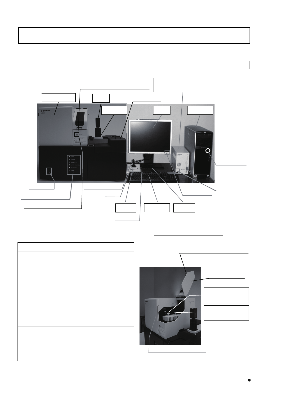
1 Description of Each User Operable Part
NOTE
As this system has been installed and adjusted by Olympus engineers at the location
specified by customers, do not touch any part other than the keyboard, the mouse or
operation parts described in this manual. After the preparations are made according to
the instructions given in Chapter 2, specimens are observed and images are acquired by
operating the controller.
1-1-1 VS120-S1/S5
Microscope
Camera
Focus dial
Monitor
Microscope control box
BX-UCB
Controller
High-speed button
Leve
Joystick
Microscope stage
VS120-S1 VS120-S5
Keyboard Mouse
Power switch
Power switch
Power switch
Specimen holder open/close slider
Specimen holder open/close slider
Page
7
Page 12
Description of Each User Operable Part
r
1-1-2 VS120-L100
Slide loader
Cassette cover open/close handle
Camera
Microscope control box
BX-UCB
Stage cover
Power switch
* Status indicating LED
PROCESS indicating LED
During standby: Light is off
During operation: Green light
* Status indicating LED
LED indication Function
POWER When the power is on, the
CASSETTE1 When a cassette is set on
flashes on and off.
LED lights up green.
cassette table 1 (in front), the
LED lights up green.
High-speed button
Leve
Joystick
Focus dial
Monitor
Keyboard
Controller Microscope
Power switch
Mouse
When the cassette cover is open
Cassette cover open/close handle
Power switch
Power switch
Cassette cover
CASSETTE2 When a cassette is set on
cassette table 2 (in back), the
LED lights up green.
SAFETY POSITION When the transfer arm is at the
initial position, the LED lights
up green.
COVER OPEN When the cassette cover is
open, the LED lights up yellow.
ERROR When an initialization error
occurs, the LED lights up
yellow.
8
Page
CASSETTE1:
Cassette at the front
CASSETTE2:
Cassette at the back
PROCESS indicating LED
Page 13

Preparations before Starting Observation
2 Preparations before Starting Observation
Be careful not to bump the microscope system during image acquisition. If the microscope is inadvertently
bumped during image acquisition, normal slide scan images cannot be acquired and calibration will be
necessary.
Image quality may deteriorate if vibrations occur during image acquisition. For this reason, doing work on
the table during the image acquisition should be avoided as much as possible.
Affix a one- or two-dimensional code label to a slide glass specimen on the same surface where the cover
glass is attached, within 25mm from the edge of the long side.
Do not use a slide glass specimen whose code label is coming off.
The code label may not be read properly depending on the code label condition.
* The following one- or two-dimensional codes can be read by VS120-L100.
Two-dimensional codes: QRCode, DataMatrix (ECC200), MicroQR, PDF417
Barcodes: WPC (JAN/EAN/UPC-A/UPC-E), NW-7, ITF, Industrial2of5, Code39, Code93, Code128,
Handling and operating precautions
RSS-14, RSSLimited, RSSExpanded
If a slide glass specimen has a chip or crack in it, there is a case where it cannot be held in place on the
stage properly.
Do not use a slide glass specimen whose cover glass sticks out over the edge of the slide.
If there is dust or stains on a slide glass specimen, there are cases where the scan cannot be performed
properly. Before starting observations, remove dust or stains by wiping down the slide.
2-1 Starting the microscope system
1. Turn ON power of the controller, the monitor, the microscope control box, and the
slide loader (for VS120-L100 only). (Refer to the figures displayed in page 7 or
page 8.)
2. After Windows starts, enter your user name and password.
TIP
3. Double-click the [VS-ASW] icon on the desktop.
The VS-ASW software starts, and the stage adjustment operation begins.
The user name and password to be entered here are not the user name
and password registered on the VS120.
Page
9
Page 14

Preparations before Starting Observation
2-2 Stage operation
1. Tilt the lever (3) of the joystick to move in the X direction (1) or in the Y
(6)
(3)
direction (2).
In case of VS120-S1 and VS120-L100:
(1)
(2)
(5)
X= Right-Left direction of the stage Y= Front-Back direction of the
stage
In case of VS120-S5:
2. Turn the focus dial (5) to move in the Z direction (4) (up and down) (to
X= Front-Back direction of the stage Y= Right-Left direction of the
stage
bring a specimen into focus).
X (Right-Left)
direction
(1)
(2)
Y (Front-Back)
direction
(4)
Z (Vertical)
direction
Focus adjustment
10
Supplementary explanations
The joystick is operable when the controller power is on.
To display it on the monitor, however, the VS120 software must be started.
Operating the lever while pressing and holding down the high-speed button
(6) at the tip of the joystick allows you to move at a faster speed.
Page
Page 15

2-3 Setting a slide glass specimen
2-3-1 VS120-S1/S5
Preparations before Starting Observation
(2)
(1)
(2)
VS120-S1 VS120-S5
1. Open the specimen holder by pulling the specimen holder open/close slider (1)
toward you. Set a slide glass specimen in place.
VS120-S1: Set a slide glass specimen such that its longer side faces front and
VS120-S5: Set a slide glass specimen such that its shorter side faces the
NOTE
NOTE
Set slide glass specimens in place with the cover glass facing up
(facing the objective lens). If the cover glass is facing down, the
specimen cannot be brought into focus.
Take care that you do not touch the objective lens.
(1)
the label (2) is on the left side.
front and the label (2) is toward the front.
2. Gently return the specimen holder open/close slider back to its original position
3. In the case of the VS120-S5, set the required number of slide glass specimens in
and check that the specimen is securely seated and not tilted.
the same manner as described in steps 1 and 2.
This completes the preparations before starting observations.
Start observations and acquire images by following the instructions given in
the [simple operation] manual.
Page
11
Page 16

Preparations before Starting Observation
2-3-2 VS120-L100
(1)
NOTE
NOTE
1. Hold and lift the cassette cover open/close handle (1) of the slide loader to open
the cassette cover.
2. Take two cassettes out by holding the knob (2) at the top of the cassette.
3. Set the cassette on a level surface with the cassette lid (3) facing up.
The following additional precautions must be observed to prevent
automatic transfer errors from occurring:
Keep slide glass specimens free of moisture or water.
Clean the reverse face of a slide glass specimen to remove dust or
stains.
Do not deliver the cassette being tilted. The slide glass specimen in
the cassette may drop out.
(5)
(2)
(4)
(6)
(7)
(3)
4. Orient a slide glass specimen (4) such that the label (5) faces the lid and the cover
glass faces the knob. Insert the slide glass specimen (4) oriented this way into the
cassette.
NOTE
TIP
5. Gently set the cassette loaded with slide glass specimens upright. Hold the knob
while taking care not to tilt the cassette, hold it so the lid faces left, and then put
the cassette back into place inside the slide loader.
6. Check that the CASSETTE1 (or CASSETTE 2) status indicating LED on the front
face of the slide loader lights up green.
(6) Be careful not to insert one slide glass specimen diagonally into
two different slots.
(7) Be careful not to insert more than one slide glass specimen into a
single slot.
Slide glass specimens are transferred into the microscope system in the
order indicated by the arrow.
12
7. Close the cassette cover on the slide loader.
Page
Page 17

Preparations before Starting Observation
(1)
To take slide glass specimens out of the cassette:
1. Move latch (1) on the cassette lid upward slightly with a finger to release it.
NOTE
2. Release the latch on the other side in the same way and remove the lid.
3. After taking all specimens out of the cassette, put the cassette lid back in place.
TIP
Applying a strong force to the latch may damage the latch.
To place a slide glass directly on the microscope stage, use the handle of
the stage cover to open and close it.
For the procedure for placing the slide glass on the stage, refer to
NOTE
NOTE
NOTE
VS120-S1/S5 On page 11.
Be sure not to put slide glasses on the stage cover. When the stage
cover is opened, slide glasses may drop down onto the stage.
Tighten the screws of stage cover firmly. The stage cover may come
off if screws are loosened.
When opening the stage cover, be sure not to hit a camera and the
other units.
When closing the stage cover, be sure not to pinch your hands.
Screw
This completes the preparations before starting observations.
Start observations and acquire images by following the instructions given in
the [simple operation] manual.
Page
13
Page 18

Maintenance
3 Maintenance
3-1 Replacing the halogen lamp of the microscope
Precautions to be followed when replacing the halogen lamp during
observations or right after turning it off:
During observations or right after turning the halogen lamp off, the
lamp, lamp housing, and surrounding parts are very hot. Before
replacing the lamp with a new one, set the power switch to O (OFF),
pull out the power cord, and wait for a while until the lamp, lamp
housing, and surrounding parts cool off.
Do not directly touch the lamp. If a fingerprint or other substance gets
on the surface of the lamp, wipe it off using a soft cloth to prevent the
(5)
(4)
(1)
lifespan of the lamp from shortening or the lamp from bursting.
TIP
(2)
(6)
1. Loosen the securing screw (1) on the top surface of the lamp housing using the
hex screwdriver provided with the microscope system.
2. Remove the lamp cover (2) by lifting it up.
3. While pressing and holding down the lamp locking lever (3), hold the new halogen
(3)
lamp (4) wrapped with a piece of gauze or something similar, and horizontally
insert the pins (5) until it butts up against the socket (6). Gently release the lamp
locking lever (3) to secure the new halogen lamp in position.
4. Replace the lamp housing, and tighten the securing screw (1) while pressing it
Use a 12V halogen lamp 100WHAL-L (7724 made by Philips).
14
downward.
Page
Page 19

3-2 Correcting uneven brightness (shading correction)
If the VS120 system is used for a long period of time, the brightness of images may
become uneven.
This phenomenon is called shading. When shading occurs, the virtual slide image looks
like the one shown in the figure below. In this case, calibrations must be performed to
restore the image brightness to a normal even state.
Maintenance
Virtual slide image affected by shading
1. Set a slide glass specimen on the stage by performing the steps described in 2-3.
TIP
2. On the menu bar of the VS-ASW software, click [Acquire] and then
[Calibrations]. The [Calibrations] dialog box is displayed.
In performing calibrations to correct shading, use a slide glass specimen
that has a large transparent area (an area in which there are no cells or
tissues).
Before setting the slide glass specimen to be used for calibrations on the
stage, clean it thoroughly so that it is free from dust, dirt or stains.
Page
15
Page 20

Maintenance
<Calibrate> button
3. Select [Shading Correction] from the list in the [Calibrations] dialog box, and
click the <Calibrate> button. The [Shading Correction] dialog box is shown.
<Next> button
[Calibrations] dialog box
4. Click the <Next> button.
[Calibration] dialog box
16
Page
Page 21

<Next> button
Maintenance
5. In the [Shading Correction] dialog box, put a check in the check box for [Skip
recording dark correction image] checkbox, and click the <Next> button.
[Calibration] dialog box is displayed again.
[Calibration] dialog box
Page
17
Page 22

Maintenance
<Next> button
6. Select the magnification with which calibrations are to be performed and the items
to be calibrated, and click the <Next> button.
<Select All> button
[Calibration] dialog box
TIP
Usually all items to be calibrated are selected.
If the <Select All> button is clicked, check marks are shown in all check
boxes for all magnifications and items to be calibrated.
18
Page
Page 23

Maintenance
7. Calibrate the 2X objective lens.
After bringing the slide glass specimen into focus by viewing its live image, move it
outside the observational area of the objective lens by moving the stage
[Live image]
<Next> button
After confirming that nothing is displayed on the live image screen, click the <Next>
button in the [Calibration] dialog box.
[Calibration] dialog box
TIP
If dust, stains, etc., are noticed on the live image, clean the objective lens
and condenser lens.
For information on how to clean the lenses, refer to “Maintenance and
preservation”.
Page
19
Page 24

Maintenance
8. Calibrate the 10X objective lens.
After bringing the slide glass specimen into focus by viewing its live image, move
the stage to a position where the specimen disappears and you see only a part of
the cover glass.
[Live image]
<Next> button
After confirming that you see only a part of the cover glass on the live image screen,
click the <Next> button in the [Calibration] dialog box.
[Calibration] dialog box
20
TIP
If dust, stains, etc., are noticed on the live image, clean the objective lens
and condenser lens.
For information on how to clean the lenses, refer to “Maintenance and
preservation”.
Page
Page 25

<Finish> button
Maintenance
9. Calibrate the 20X and 40X objective lenses by performing the same steps as
performed for the 10X objective lens.
After calibrating the 40X objective lens, click the <Finish> button in the
[Calibration] dialog box. This completes the calibrations for correcting the
shading phenomenon.
<Close> button
[Calibration] dialog box
10. Close the [Calibration] dialog box by clicking the <Close> button.
[Calibration] dialog box
Page
21
Page 26

Maintenance
3-3 Overview Image Area Settings
When acquiring the image by VS120, acquire the overview image (2x magnification) of
the entire slide glass specimen first, and then acquire the image in the specified area by
the specified magnification.
Though the area to acquire the overview image has been preset at setup time, you can
set the area and save the overview image by yourself.
3-3-1 Overview Image Area Settings
1. Set the slide glass specimen on the stage according to procedures described in
[Scan] tab
Chapter 2-3.
2. Click [Scan] tab on the upper-right of the VS-ASW software screen. [Stage
Navigator] tool window will be displayed on the lower-right of the screen.
[Stage Navigator] tool window
22
3. Click [Define Overview Area] in the tool bar of [Stage Navigator] tool window.
[Define Overview Area] dialog box will be displayed.
[Define Overview Area]
Page
Page 27

Maintenance
4. Move the stage to position in the figure below. When the position is determined,
click <OK> button in [Define Overview Area] dialog box.
VS120-S1 and VS120-L100 VS120-S5
When you are using the VS120-S5, click button 1 on the Stage Navigator tool
window.
[Define overview area] dialog box
5. Move the stage to
click <OK> button in [Define Overview Area] dialog box.
VS120-S1 and VS120-L100 VS120-S5
position in the figure below. When the position is determined,
[Define overview area] dialog box
The overview image area has been defined.
Page
23
Page 28

Maintenance
3-3-2 Save Overview Image Area
1. Click [Save Overview Area] in the tool bar of [Stage Navigator] tool window.
[Save Overview Area] dialog box will be displayed.
2. Input the name in [Name] text box of [Save Overview Area] dialog box, and click
<OK> button. The current overview image area will be saved.
[Save Overview Area]
[Save Overview Area] dialog box
24
Page
Page 29

3-3-3 Read Overview Image Area
1. Click [Load Overview Area] in tool bar of [Stage Navigator] tool window.
[Load Overview Area] dialog box will be displayed.
2. Select the name of the overview image are in [Load Overview Area] dialog box,
and click <OK> button. The selected overview image area will be read-in.
Maintenance
[Load Overview Area]
[Load Overview Area] dialog box
Page
25
Page 30

Trouble Shooting
4 Trouble Shooting
Depending on how the system is used, it may not take full performance of the system, though it is not a failure.
When a trouble occurs, see the followings and exercise appropriate action.
In case that the trouble is not yet recovered, then, contact Olympus local office immediately.
Problem Cause Remedy Page to
refer
The image cannot be
acquired by VS-ASW
software.
The image is too dark. The objective lens or the condenser
The lamp is burned out. Replace the lamp. 14
The illumination filters on the right
The image color is
strange.
The overview image area is not set. Set the overview image area or
read-in the saved settings.
Clean the objective lens or the
lens is dirty.
side of the microscope main body
are different from the setup status.
(See the figure below.)
The illumination filters on the right
side of the microscope main body
are different from the setup status.
(See the figure below.)
condenser lens.
For cleaning, be sure not to remove
the objective lens or the condenser
lens.
Set the illumination filters correctly.
ND6: OUT
ND25: OUT
LBD: IN
OP: OUT
In general, do not change the
position of the illumination filters.
Set the illumination filters correctly.
ND6: OUT
ND25: OUT
LBD: IN
OP: OUT
In general, do not change the
position of the illumination filters.
22
4
-
-
The image brightness is
uneven.
The shading is not adjusted
Unable to focus The specified slide glass specimen
The slide glass specimen is set to
26
Page
The objective lens or the condenser
lens is dirty.
correctly.
is not being used.
the opposite direction.
Clean the objective lens or the
condenser lens.
For cleaning, be sure not to remove
the objective lens or the condenser
lens.
Adjust the shading correctly. 15
Use the specified slide glass
specimen.
Set the slide glass specimen to the
correct direction.
4
29
11
Page 31

Trouble Shooting
Problem Cause Remedy Page to
refer
The one side of the image
blurs.
The slide glass specimen is set
The slide glass specimen
cannot be loaded correctly
by the slide loader.
(For VS120-L100 only)
The reverse face of the slide glass
The slide glass specimen is
Multiple slide glass specimens are
The durable time of vacuum pump
The slide glass specimen
was dropped into the slide
loader.
(For VS120-L100 only)
A foreign substance is stuck in the
stage or the specimen holder.
tilted.
Moisture is adhered to the slide
glass specimen.
specimen is dirty.
inserted diagonally into 2 different
slots of the cassette.
inserted in one slot of the cassette.
in the slide loader has passed.
The slide glass specimen was
dropped due to incorrect loading
occurred by causes described
above.
Remove the foreign substance and
clean the stage or the specimen
holder.
Set the slide glass specimen again
so as not to be tilted.
Wipe out moisture from the slide
glass specimen.
Clean the reverse face of the slide
glass specimen.
Insert the slide glass specimen in
the cassette correctly.
Insert the slide glass specimen in
the cassette correctly.
Contact to Olympus local office. 4
Switch OFF the power of the slide
loader. Open the cassette cover or
the side cover, and remove the
dropped slide glass specimen with
the tweezers.
If the slide glass specimen was
dropped in the place where it’s hard
to remove, contact to Olympus local
office.
Cassette cover
Side cover
11
12
12
12
12
4
-
Page
27
Page 32

Trouble Shooting
Problem Cause Remedy Page to
refer
The slide glass specimen
inserted in the cassette
cannot be detected by the
slide loader.
(For VS120-L100 only)
The information of the
slide barcode is displayed
as “NL”.
(For VS120-L100 only)
The position to affix the code label
The code label is not affixed. Affix the code label on the proper
Some kinds of slide glass specimen
which has chamfered corners as
described below might not be
detected by the slide loader.
Section of slide glasses
The direction to insert the slide
glass specimen is not correct.
is not correct.
Set the slide glass specimen onto
the stage directly.
Alternatively, use a slide glass
specimen which has right-angled
corner.
Insert the slide glass specimen in
the cassette correctly.
Affix the code label on the proper
position.
position.
-
12
9
9
The information of the
slide barcode is displayed
as “ND”.
(For VS120-L100 only)
Space around the code is too small. Secure enough space around the
Print of the code is too rough. Increase the resolution of the print.
The code print size is too small. Enlarge the code print size. -
The information of the
slide barcode is not
reflected to the file name.
(For VS120-L100 only)
The coding area is dirty. Clean the coding area. 9
code.
(600dpi or more)
Special characters ¥ / : * ? < > | or
the line feeds are included in the
code data.
Do not include special characters
¥ / : * ? < > | or the line feeds in the
code data.
-
-
-
28
Page
Page 33

Specifications
5 Specifications
VS120-S1 VS120-S5 VS120-L100
Specimens to be
observed
Specially-designed
optical microscope
Specially-designed
digital camera
Slide transfer
system
Scan
System control
Other
Observable
specimens
Compatible slide
glass
Compatible cover
glass
Observation method Transmitted light brightfield observation (Koehler illumination)
Objective lens Automatic switching between 2X, 10X, 20X, and 40X objective
Motorized stage Automatic control via motorized XY stage
Focusing Auto focus control via motorized focusing
Image correction Shading correction, white-balance function
Number of slide glass
specimens
Scan area
Resolution
Scan speed
controller DOS/V compatible controller (Windows 7 Professional English
Network Ethernet (100/1,000)
Memory 4GB
Storage 1.0 TB or more
Display 24-inch wide-screen LCD monitor
Software
Rated voltage/current Refer to page 31.
Weight About 52 kg
Operating
environment
Electric power
consumption
Tissue specimen fixed on a slide glass with cover glass
Width: 25 to 26 mm, length: 75 to 76 mm, thickness: 0.8 to 1.4 mm
Thickness: 0.12 to 0.17 mm
lenses
1 slide
(setting onto the
stage directly)
Width: 26 mm, length: 64 mm (slide glass 26 mm wide 76 mm
long)
0.33 m/pixel or less when the 20X objective lens is used
About 2 minutes (area of 15 mm 15 mm when the 20X objective
lens is used)
version)
Image saving format (proprietary format, JPEG, TIFF), a zoomed-in
image can be observed during image acquisition, annotation
function, automatic recognition of the position of a specimen, Z
stack function, EFI function, one-shot image acquisition function,
stepless scaling function, multiple image synchronized display
function, gluing together of images, consultation software (optional)
- Control of 5-piece
(including the weight
of the main body,
controller, and
monitor)
Temperature: 15 to 28C, humidity: 30 to 80% (no condensation)
960W 960W 1030W
A maximum of 5
slides
(setting onto the
stage directly)
slide image
acquisition
About 52 kg
(including the weight
of the main body,
controller, and
monitor)
A maximum of 100
slides
(transferring onto the
stage by using the
slide loader)
Control of the
automatic transfer
system
About 100 kg
(including the weight
of the main body,
controller, and
monitor)
Page
29
Page 34

Specifications
■ Controller: VS120-PC-E
Item Specification
Controller OS: Windows 7 Professional 32 bit, English version
Rating 100-120V/200-240V ~ 50/60Hz 10A/6A
Outside dimensions, weight (not
including the dimensions or
weight of protruding parts)
■ Microscope control box: BX-UCB
Item Specification
Rating 100-120V/220-240V ~ 50/60Hz 3.5A/1.5A
Outside dimensions, weight (not
including the dimensions or
weight of protruding parts)
The specially-designed XYZ control board is built in.
167.9 (W) 445.3 (D) 450.2 (H) mm, about 15 kg
125 (W) 332 (D) 216 (H) mm 5 kg
■ Slide loader: VS120-LD100
Item Specification
Rating 100-120V/220-240V ~ 50/60Hz 0.9A/0.5A
Outside dimensions, weight (not
including the dimensions or
weight of protruding parts)
■ Monitor: VS-MON24W
Item Specification
Image size 24-inch wide-screen LCD display
Rating 100-240V ~ 50/60Hz 1.5A
Outside dimensions, weight (not
including the dimensions or
weight of protruding parts)
720 (W) 587 (D) 637 (H) mm 55 kg
556 (W) 235 (D) 525 (H) mm (including the
fixed-type base, when the monitor is set to its highest
position), about 8.5 kg
30
Page
Page 35

■ Operating environment
Item Specification
- Indoor use
Altitude Max. 2000 meters
Operating temperature
Operating humidity 30 to 80% RH (no condensation)
Supply voltage fluctuations
Overvoltage category II (IEC60664)
Degree of contamination 2 (IEC60664)
Specifications
15 to 28°C
±10%
■ Rated voltage/current
Before connecting each of the following pieces of equipment to the AC outlet, check the capacity of the AC
outlet to be used.
Computer
VS120-PC-E
100-120/200-240V ~
50/60Hz 10A/6A
Microscope controller
BX-UCB
100-120/220-240V ~
50/60Hz 3.5A/1.5A
Monitor
VS-MON24W
100-240V ~
50/60Hz 1.5A
Slide loader
VS120-LD100
100-120/220-240V ~
50/60Hz 0.9A/0.5A
Page
31
Page 36

Lamp housing Inspection sheet
6 Lamp housing Inspection sheet
Study the instruction manual for the lamp housing before inspection.
NOTE
For safe use of the lamp housing, we recommend performing the following inspection
periodically (every time you replace
the lamp bulb and at least every 6 months).
The table below identifies the check items to be observed. Put (X) if not applicable or (
if applicable.
If there is any (X) mark noted, immediately stop use of the product, and contact Olympus
for detailed inspections or replace the lamp housing.
If you detect an abnormality other than that listed below or with other Olympus product,
also stop the use of the product and contact Olympus for detailed inspections.
Note that the service, replacement and detailed inspections are charged after expiration of
the warranty period.
)
If you have any questions, please contact Olympus.
Check results (Date)
Check items / / / /
1. More than 8 years have passed since original purchase or the total
power ON time has exceeded 20,000 hours.
2. Lamp does not light sometimes even though the power switch is set
to on.
3. Illumination flickers when you move the lamp cable or lamp housing.
4. Lamp cable is unusually hot to the touch.
5. Scorching or burning odor is produced during use.
6. Illumination still flickers after replacement with a new lamp bulb.
7. Deformation, backlash, or looseness, etc. when you assemble the
lamp housing.
(Impossibility of removing the top section of lamp housing when you
attempt to replace the lamp bulb, etc.)
8. Extreme discoloration of the lamp housing connection terminal or
lamp socket.
Uneven discoloration of the left and right sections of these parts.
9. Discoloration, deformation or cracking of the lamp housing.
10. Melting, crack, deformation or solidification of the lamp cable or a
wiring part.
11. Increased frequency of servicing compared to similar devices put
into use at the same time as the lamp housing.
* When the Check Result columns become insufficient, copy this sheet.
32
Page
Page 37

Proper Selection of the Power Supply Cord
If no power supply cord is provided, please select the proper power supply cord for the equipment by referring
to “Specifications” and “Certified Cord” below;
CAUTION: In case you use a non-approved power supply cord for Olympus products, Olympus can no
longer warrant the electrical safety of the equipment.
Specifications
Voltage Rating
Current Rating
Temperature Rating
Length
Fittings Configuration
125V AC(for 100-120V AC area) or , 250V AC (for 220-240V AC area)
10A minimum (for 100-120V AC area) or, 6A minimum (for 200-240V AC area)
60C minimum
3.05 m maximum
Grounding type attachment plug cap. Opposite terminates in molded-on IEC
configuration appliance coupling.
Table 1 Certified Cord
A power supply cord should be certified by one of the agencies listed in table 1, or comprised of cordage
marked with an agency marking per Table 1 or marked per Table 2. The fittings are to be marked with at least
one of agencies listed in Table 1. In case you are unable to buy locally in your country the power supply cord
which is approved by one of the agencies mentioned in Table 1, please use replacements approved by any
other equivalent and authorized agencies in your country.
Country Agency
Australia SAA
Austria ÖVE
Belgium CEBEC
Canada CSA
Denmark DEMKO
Certification
Mark
Country Agency
Italy IMQ
Japan
Netherlands KEMA
Norway NEMKO
Spain AEE
JET, JQA, TUV,
UL-APEX/MITI
Certification
Mark
Finland FEI
France UTE
Germany VDE
Ireland NSAI
Sweden SEMKO
Switzerland SEV
United Kingdom ASTA,BSI
U.S.A UL
Page
33
Page 38

Table 2 HAR Flexible Cord
APPROVAL ORGANIZATIONS AND CORDAGE HARMONIZATION MARKING METHODS
Alternative Marking Utilizing
Black-Red-Yellow Thread
(Length of color section in mm)
Black Red Yellow
Approval Organization
Printed or embossed Harmonization
Marking (May be located on jacket or
insulation of internal wiring)
Comite Electrotechnique Belge
(CEBEC)
Verband Deutscher Elektrotechniker
(VDE) e.V.Prüfstelle
Union Technique de d’Electricite’ (UTE)
Instituto Italiano del Marcio di Qualita’
(IMQ)
British Approvals Service for Electric
Cables (BASEC)
N.V. KEMA
SEMKO AB Svenska Elektriska
Materielkontrollanstalter
Österreichischer Verband für
Elektrotechnik (ÖVK)
Danmarks Elektriske Materielkontrol
(DEMKO)
National Standards Authority of Ireland
(NSAI)
CEVEC <HAR> 10 30 10
<VDE> <HAR> 30 10 10
USE <HAR> 30 30 10
IEMMEQU <HAR> 10 30 50
BASEC <HAR> 10 10 30
KEMA-KUER <HAR> 10 30 30
SEMKO <HAR> 10 10 50
<ÖVK> <HAR> 30 10 50
<DEMKO> <HAR> 30 10 30
<NSAI> <HAR> 30 30 50
Norges Elektriske Materiellkontroll
(NEMKO)
Asociacion Electrotecnica Y Electronica
Espanola (AEE)
Hellenic Organization for
Standardization (ELOT)
Instituto Portugues da Qualidade (IPQ)
Schweizerischer Elektro Technischer
Verein (SEV)
Elektriska Inspektoratet
Underwriters Laboratories Inc.(UL) SV,SVT,SJ or SJT,3 X 18AWG
Canadian Standards Association (CSA) SV,SVT,SJ or SJT,3 X 18AWG
34
Page
NEMKO <HAR> 10 10 70
<UNDE> <HAR> 30 10 70
ELOT <HAR> 30 30 70
| np | <HAR> 10 10 90
SEV <HAR> 10 30 90
SETI <HAR> 10 30 90
Page 39

Page 40

Shinjuku Monolith, 3-1, Nishi Shinjuku 2-chome, Shinjuku-ku, Tokyo, Japan
Wendenstrasse 14-18, 20097 Hamburg, Germany
3500 Corporate Parkway, Center Valley, Pennsylvania 18034-0610, U.S.A.
491B River Valley Road, #12-01/04 Valley Point Office Tower, Singapore 248373
31 Gilby Road, Mount Waverley, VIC., 3149, Melbourne, Australia
Blue Lagoon Drive, Suite 290 Miami, FL 33126, U.S.A.
5301
Printed in Japan on April 18, 2011 M 001–02
 Loading...