


Artisan Technology Group is your source for quality
new and certied-used/pre-owned equipment
• FAST SHIPPING AND
DELIVERY
• TENS OF THOUSANDS OF
IN-STOCK ITEMS
• EQUIPMENT DEMOS
• HUNDREDS OF
MANUFACTURERS
SUPPORTED
• LEASING/MONTHLY
RENTALS
• ITAR CERTIFIED
SECURE ASSET SOLUTIONS
SERVICE CENTER REPAIRS
Experienced engineers and technicians on staff
at our full-service, in-house repair center
WE BUY USED EQUIPMENT
Sell your excess, underutilized, and idle used equipment
We also offer credit for buy-backs and trade-ins
www.artisantg.com/WeBuyEquipment
REMOTE INSPECTION
Remotely inspect equipment before purchasing with
our interactive website at www.instraview.com
LOOKING FOR MORE INFORMATION?
Visit us on the web at www.artisantg.com for more
information on price quotations, drivers, technical
specications, manuals, and documentation
Contact us: (888) 88-SOURCE | sales@artisantg.com | www.artisantg.com
SM
View
Instra

INVERTED RESEARCH
MICROSCOPE
This instruction manual has been written for use of the
Olympus lnverted Research Microscope Model IMT-2. Before
putting the microscope into operation, it is recommended
that you read this manual carefully in order to familiarize
yourself fully with the use of this microscope so that you
may obtain optimum performance of this instrument.
----
Artisan Technology Group - Quality Instrumentation ... Guaranteed | (888) 88-SOURCE | www.artisantg.com

IBEFORE USE
Observe the following points carefully for operation and maintenance:
1.
Operation
@ As a microscope is a precision instrument, always handle
it with the care it deserves, and avoid abrupt motions
and shocks.
0
a
0
0
8
0
2.
To lift the microscope from the packing case, hold it
at the OM mount (A) and the fluorescence illuminator
mounting thread (B). (Fig. 1)
To move the microscope
Hold the microscope by the OM mount (A) and the
fluorescence illuminator mounting thread (B) or place
your hands under the microscope base at the microscope
side (C) and back (D).
Do not grasp the plastic hand rests, since they are not
strong enough to support the microscope.
Do not use any bulb other than the one designated by
Olympus (12V50WHAL halogen bulb).
Avoid exposure of the microscope to direct sunlight,
(Model IMT2SFR shown)
high temperature and humidity, dust and vibration.
Make it a point to use the tension adjustment ring to adjust the tension of the coarse adjustment knobs. (
not rotate the coarse adjustment knobs in the opposite directions simultaneously.)
Make sure that the line voltage selector switch is set to conform with the local mains voltage.
Disconnect the power cord from the AC outlet before fuse replacement.
Always ground the microscope.
Maintenance
:Do
@ Lens surfaces must always be kept clean. Fine dust on lens surfaces should be blown off by means of a hand
blower. Carefully wipe off oil or fingerprints on the lens surfaces with gauze moistened with a small amount
of xylene, or a cleaning medium (alcohol and ether 3 : 7).
@ Do not use organic solutions to wipe the surfaces of various plastic components.
@ Be careful not to spill the culture solution, etc. If spilt, it should be wiped off immediately. It is recommended
to use a waterproof cover optionally available.
@ When objectives are not screwed into the nosepiece apertures, seal the apertures with dust plugs, which will
protect the lenses located in the lower light path from dust, culture solutron, etc.
@ After use the microscope should be covered with the vinyl dust cover provided and stored in a place free from
humidity.
Artisan Technology Group - Quality Instrumentation ... Guaranteed | (888) 88-SOURCE | www.artisantg.com

5-l
Observation Procedure
.............................
10
5-2
Operation of Individual Components
..................
11
6-l
Photomicrographic System
..........................
18
6-2
Taking Pictures
...................................
20
Artisan Technology Group - Quality Instrumentation ... Guaranteed | (888) 88-SOURCE | www.artisantg.com

I tern
vlicroscope
Specifications
Focus adjustment by vertical movement of the nosepiece (stage is fixed in position) by means
#sand of the coaxial coarse and fine adjustment knobs,
roller guide stroke (from the focal point on
the stage surface). 8mm upward and 2mm downward; with reduction gear, graduated rn tncrements of 2g.
\Josepiece.
Sextuple, with provision for mountrng the Nomarski slrder attachment, detachable.
Gtage:
Cross-movement stage
IMT2SVR
Square plain stage
Mechanical stage
attachment IMT2-MVR
Ilumination:
Light source
Filter holder
t
Condenser holder
200mm x 200 mm, traversing area 50mm x 50 mm;
with low positioned coaxial control knobs; 2 insert plates, outside diameter 1 lOmm,
inside diameters 20 mm and 50 mm respectively.
200mm x 2OOmm, traversing area 50mm x 50 mm;
with low positioned coaxial control knobs; 2 insert plates, outside diameter 1 IOmm,
inside diameters 20 mm and 50 mm respectively, low flexible.
160 mm x 220 mm;
insert plate, outside diameter 110 mm. Substage
provided; provision for attaching the mechanical stage IMT2-MVR.
Traversing area 110mm x 72mm; attachable at the right or left side
on the plain stage.
Provision for accommodation of various culture vessels and specimen
holders.
Halogen bulb 12V50WHAL, with bulb centering device and light intensive control; Voltage indication by bar graph voltmeter.
Provided with 4 flip-up filter holders; green interference filter and
frosted filter.
Flip-up, swing-out type; circular mounting dovetail for slide-in condenser;
vertical movement on rack-and-pinion, condenser centering
knobs; tension adjustment of the height adjustment knob.
Observation
system.
Built-in magnification changer, with centering telescope 1 X-1 .5X-CT.
Light path for photomicrography, 3-setting positions, linked with focusing retitles; for observa-
tion tube (BI), 35mm camera (OM) and multi-tube mounting port (MTU).
Binocular tube, inclined 45’; interpupillary distance adjustment from 53 mm to 75mm; constant
tube length adjustment.
Eyepieces WHKlOX, WHKIOX-H (field number 20)
OM light path: 2.5X FK photo eyeprece built-in; OM system bayonet mount.
Multi-tube light path; provision for mounting the PM-10 photomicrographic equipment directly
as well as the multi-tube attachment.
Condenser.
Objectives.
Long working distance turret condenser; N.A. 0.55, W.D. 21 mm, light annuli for 4X, 10X,
20X and 40X objectives and empty aperture; aperture iris diaphragm.
Ultra long working distance condenser,
N.A. 0.30, W D. 55mm, Light annul1 for 4X, 10X,
20X, and 40X objectives plus empty aperture; aperture Iris diaphragm.
Phase contrast objectives PC S Plan 4XPL
N.A. 0.13, W.D 15.5 mm
PC S Plan 1OXPL
N.A. 0.30,*W.D. 7.5mm
LWD-CD Plan 20XPL N.A. 0.40, W.D. 3.0 mm
with correction collar
LWD-CD Plan 4OXPL N.A. 0.60, W.D. 1.9 mm
wrth correction collar
Dimensions:
320 mm (W) x 395mm (D) x 600 mm (H) Eyepoint 405 mm
Stage height 275 mm
Weight:
20.5 kg (outfitted with standard equipment)
Artisan Technology Group - Quality Instrumentation ... Guaranteed | (888) 88-SOURCE | www.artisantg.com

Component
Microscope stand,
with built-in magnification changer (1X-l .5X-CT),
built-in 2.5X photo eyepiece, 50W halogen illuminator, condenser holder, hand rests (paired), dust
cover, filter 431F550-W45 and screw driver
Power cord
Binocular tube, 45’ inclined
Intermediate tube
;extuple revolving nosepiece
jOW halogen lamp housing
jOW halogen bulbs, 2 PCS.
Iross-movement mechanical stage with right-hand
ow drive controls
:ross-movement mechanical stage with right-hand
ow flexible
Model
I MT-2-l 1 I MT-2-l 2
I MT2-F
0
0
UYCP
0
0
BH2-B145
0
0
I MT2-ATU
0 0
IMT2-RE
0
0
IMT2-LSH
0
0
JC12V50WHAL 0
0
I MT2-SVR
;quare plain stage
nechanical stage attachment with low drive controls
-ong working distance turret condenser
Jltra long working distance turret condenser
Objectives
Eyepieces
IMT2-SFR
IMT2-SP2 0 0
I MT2-MVR 0
0
IMT2-LWCD 0
IMT2-U LWCD
0
0
PCSPL4XPL
0
PCSPLlOXPL
0 0
LWDCDPL2OXPL 0
LWDCDPL40XPL
I::::::-, / : 1 i
Note: 0 indicates the compatible components for Model IMT-2-1 l/ IMT-2-12/lMT-2-21/IMT-2-31.
vlT-2-21 I MT-2-31
0 I 0
I
O I 0
T
0
0 I 0
I
0 I 0
0
0
0
0
l-
0
0
0
0
Artisan Technology Group - Quality Instrumentation ... Guaranteed | (888) 88-SOURCE | www.artisantg.com

Field iris diaphragm
lever
Lamp housing
Long working distance
condenser
Stage insert plate
omarski slider
insertion slot
%\
insertion slot
Exciter filter
Multi-tube mounting
-I~ ~.
aaapTer
Main switch
(IMT-2-12 shown)
\Eyepiece
Diopter adjustment
Observation tube
ring
\
Line voltage selector
switch
Artisan Technology Group - Quality Instrumentation ... Guaranteed | (888) 88-SOURCE | www.artisantg.com

Lamp housing
/
\
Bulb horizontal centering
Bulb socket clamping/
ong working
distance
condenser
---.
Condenser height
Condenser holder
clamoina knob
Stage cross-movement
knobs
Light excluding shutter kno
Light
path selector knot
-
BI
: for binocular tub{
OM : fboa;;5mrn camen
.
I
\
Minimum line voltage
Tension adjustment knob
‘/
/ /Frne adjustment knob
1 Hand resr\ se’ector knob
e
3
Coarse adjustment knob
I
Light intensity
control lever
( IMT-2-12 shown)
Artisan Technology Group - Quality Instrumentation ... Guaranteed | (888) 88-SOURCE | www.artisantg.com
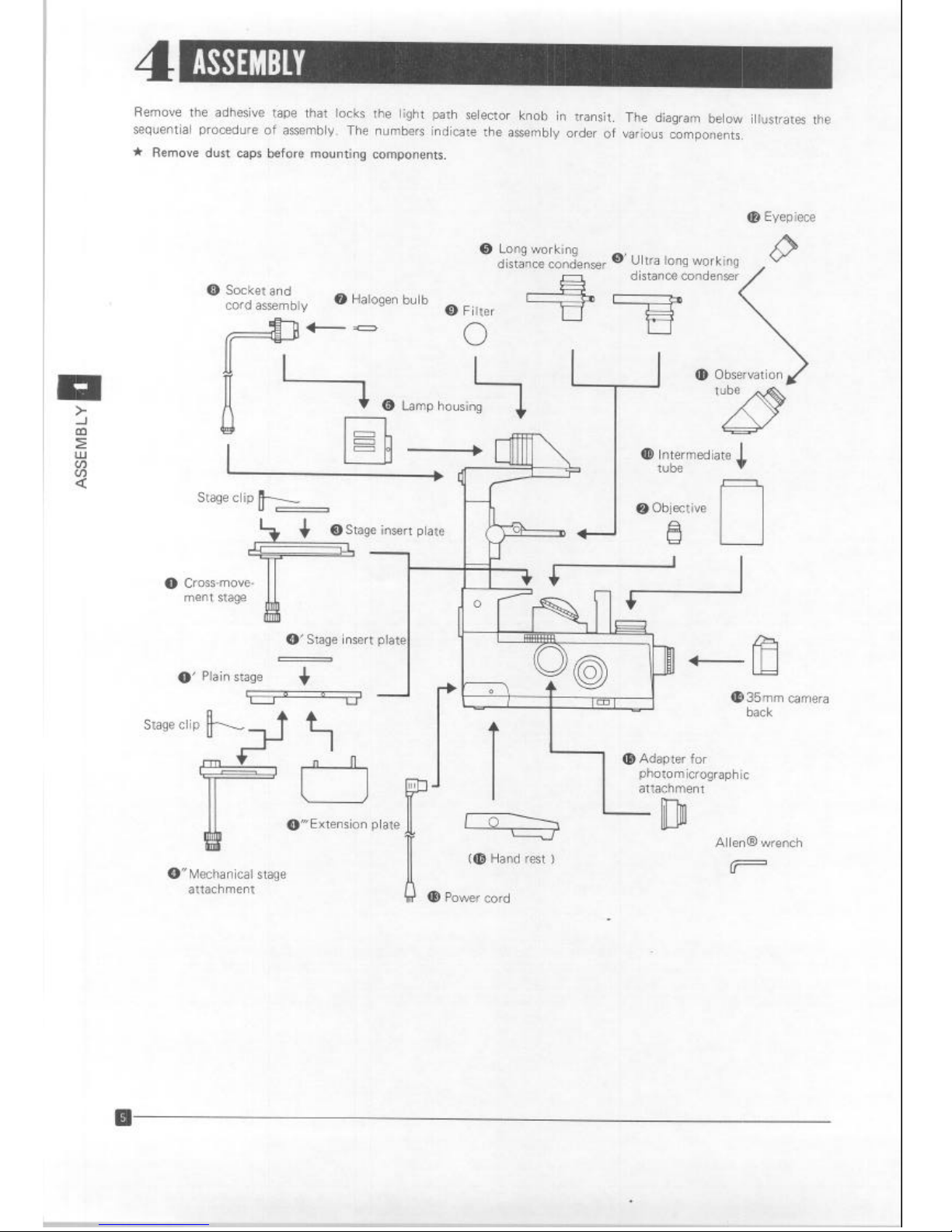
Remove the adhesive tape that locks the light path selector knob in transit. The diagram below illustrates the
sequential procedure of assembly. The numbers indicate the assembly order of various components.
It Remove dust caps before mounting components.
CD Eyepiece
(i) Long working
distance condenser
0’ Ultra long working
distance condenser
0 Socket and
cord assembly
0 Halogen bulb
@ Filter
0
Lamp housing
4
Stage clip
k
@ Objective
!!3
L
+ I
0 Cross-move- 11
0’ Stage insert plate
,
0’ Plain stage
+
I
0
o’y, ~
n. I.
R
4 A
ment stage
ii!
I
@35mm camera
back
-1
@Adapter for
photomicrographic
attachment
@“Extension plate L
lr -
Allen@ wrench
0” Mechanical stage
attachment
Cm Hand rest )
m Pnrnmr r.r\rA
Artisan Technology Group - Quality Instrumentation ... Guaranteed | (888) 88-SOURCE | www.artisantg.com
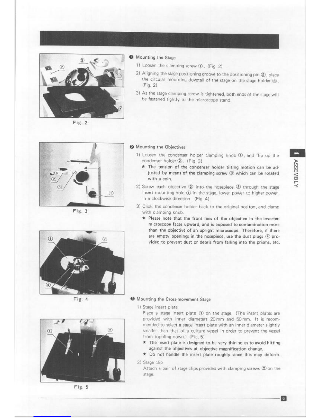
Fig. 2
L-1
q
Fig. 3 Fig. 3
Fig. 4
0
Mounting the Stage
) Loosen the clamping screw 0. (Fig. 2)
) Aligning the stage positioning groove to the positioning pin 0, place
the circular mounting dovetail of the stage on the stage holder 0.
(Fig. 2)
) As the stage clamping screw is tightened, both ends of the stage will
be fastened tightly to the microscope stand.
0 Mounting the Objectives
1) Loosen the condenser holder clamping knob 0, and flip up the
condenser holder 0. (Fig. 3)
>
* The tension
of the condenser holder tilting motian can be ad-
E
justed by means of the clamping screw @ which can be rotated
a
with a coin.
P
2) Screw each objective @ into the nosepiece @ through the stage
i
insert mounting hole @ in the stage, lower power to higher power,
in a clockwise direction. (Fig. 4)
3) Click the condenser holder back to the original positon, and clamp
with clamping knob.
* Please note that
the front lens of the objective in the inverted
microscope faces upward, and is exposed to contamination more
than the objective of an upright microscope. Therefore, if there
are empty openings in the nosepiece, use the dust plugs 0 provided to prevent dust or debris from falling into the prisms, etc.
0 Mounting the Cross-movement Stage
1) Stage insert plate
Place a stage insert plate @ on the stage. (The insert plates are
provided with inner diameters 20 mm and 50 mm. It is recommended to select a stage insert plate with an inner diameter slightly
smaller than that of a culture vessel in order to prevent the vessel
from toppling down.) (Fig. 5)
* The insert plate is designed to be very thin so as to avoid hitting
against the objectives at objective magnification change.
Ir Do not handle the insert plate roughly since this may deform.
2) Stage clip
Attach a pair of stage clips provided with clamping screws @ on the
stage.
Fig. 5
Artisan Technology Group - Quality Instrumentation ... Guaranteed | (888) 88-SOURCE | www.artisantg.com

/
/
Fig. 6
Fig. 7
0 Attaching the Plain Stage
1) Insert plate (I MT2SP2)
Aligning the guide pin @ of the insert plate with the notch @ in
the stage, mount the insert plate. (Fig. 6)
2) Mechanical stage attachment (IMT2-MVR)
Attach the mechanical stage attachment to the lower rrght side of
the plain stage, tightening the clamping screw @ with a coin. (Fig. 7)
* If no photographic equipment, such as the PM-1OAD equipment,
etc. is attached to the “MTU” light exit port of the microscope
base, the stage attachment can be attached on the left side of the
plain stage.
3) Stage extension plate
Align the guide pins of the extension plate 0 into the positioning
holes in the plain stage, and attach securely. (Fig. 8)
Fig. 8
0 Attaching the Condenser
Insert the circular dovetail of thg condenser into the condenser holder,
and clamp with knob @ (Fig. 9)
Fig. 9
Artisan Technology Group - Quality Instrumentation ... Guaranteed | (888) 88-SOURCE | www.artisantg.com
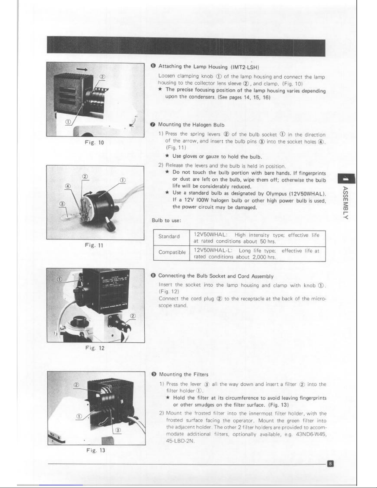
@ Attaching the Lamp Housing (lMT2-LSH)
Loosen clamping knob 0 of the lamp housing and connect the lamp
housing to the collector lens sleeve 0, and clamp. (Fig. 10)
*
The
precise focusing position of the lamp housing varies depending
upon the condensers. (See pages 14, 15, 16)
0 Mounting the Halogen Bulb
1) Press the spring levers @ of the bulb socket @ in the direction
of the arrow, and insert the bulb pins @I into the socket holes 0.
(Fig. 11)
* Use gloves or gauze to hold the bulb.
2) Release the levers and the bulb is held in position.
* Do not touch the bulb portion with bare hands. If fingerprints
or dust are left on the bulb, wipe them off; otherwise the bulb
life will be considerably reduced.
* Use a standard bulb as designated by Olympus (12V50WHAL).
If a 12V IOOW halogen bulb or other high power bulb is used,
the power circuit may be damaged.
Bulb to use:
Fig.
11
Standard
12V50WHAL: High intensity type; effective life
at rated conditions about 50 hrs.
Compatible
12V50WHAL-L: Long life type; effective life at
rated conditions about 2,000 hrs.
Fig. 12
0 Connecting the Bulb Socket and Cord Assembly
Insert the socket into the lamp housing and clamp with knob 0.
(Fig. 12)
Connect the cord plug @ to the receptacle at the back of the micro-
scope stand.
0 Mounting the Filters
1) Press the lever @ all the way down and insert a filter @ into the
filter holder 0.
* Hold the filter at its circumference to avoid leaving fingerprints
or
other
smudges on the filter surface. (Fig. 13)
2) Mount the frosted filter into the innermost filter holder, with the
frosted surface facing the operator. Mount the green filter into
the adjacent holder. The other 2 filter holders are provided to accommodate additional filters, optionally available, e.g. 43ND6-W45,
45.LBD-2N.
Fig. 13
Artisan Technology Group - Quality Instrumentation ... Guaranteed | (888) 88-SOURCE | www.artisantg.com
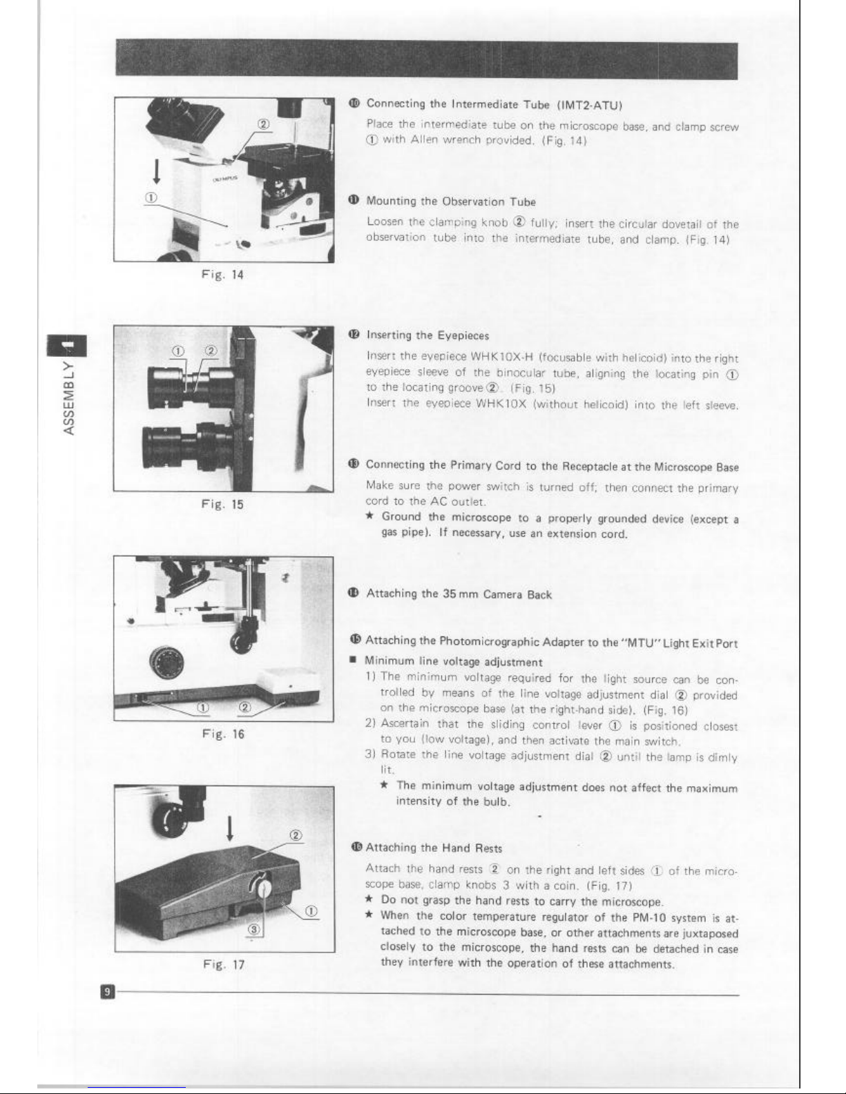
Fig. 14
Fig. 15
Fig. 16
I
I
Fig. 17
Connecting the Intermediate Tube (lMT2-ATU)
Place
the intermediate tube on the microscope base, and clamp screw
@ with Allen wrench provided. (Fig. 14)
Mounting the Observation Tube
Loosen the clamping knob @ fully, insert the circular dovetail of the
observation tube into the intermediate tube, and clamp. (Fig. 14)
@ Inserting the Eyepieces
Insert the eyepiece WHKlOX-H (focusable with helicoid) into the right
eyepiece sleeve of the binocular tube, aligning the locating pin @
to the locating groove@. (Fig. 15)
Insert the eyepiece WHKlOX (without helicoid) into the left sleeve.
@ Connecting the Primary Cord to the Receptacle at the Microscope Base
Make sure the power switch is turned off; then connect the primary
cord to the AC outlet.
* Ground the microscope to a properly grounded device (except a
gas pipe). If necessary, use an extension cord.
Attaching the 35mm Camera Back
Attaching the Photomicrographic Adapter to the “MTU” Light Exit Port
Minimum line voltage adjustment
1) The minimum voltage required for the light source can be controlled by means of the line voltage adjustment dial @ provided
on the microscope base (at the right-hand side). (Fig. 16)
2) Ascertain that the sliding control lever @ is positioned closest
to you (low voltage), and then activate the main switch.
3) Rotate the line voltage adjustment dial @ until the lamp is dimly
lit.
* The minimum voltage adjustment does not affect the maximum
intensity of the bulb.
a!) Attaching the Hand Rests
Attach the hand rests ,z on the right and left sides 0 of the microscope base, clamp knobs 3 with a coin. (Fig. 17)
* Do not grasp the hand rests to carry the microscope.
* When the color temperature regulator of the PM-10 system is at-
tached to the microscope base, or other attachments are juxtaposed
closely to the microscope, the hand rests can be detached in case
they interfere with the operation of these attachments.
Artisan Technology Group - Quality Instrumentation ... Guaranteed | (888) 88-SOURCE | www.artisantg.com

Normal procedure
Adjustment necessary for operation
Swing out the_ filters.
Lower the
nosepiece.
1 Swing in the 1 OX objective.
F
Rotate the condenser turret to “ 0 @
position. Stop down the aperture iris dia- . . . . .
phragm for low contrast specimens.
I
lnterpupillary distance adjustment
. . . . . . . . . . . . . . . . .._.....
. .
Diopter adjustment
I
. . . . . . . . . . . . . . . . . . . . . . . . . . .
*
1 Focus
. . . . . . . . . . . . . . . . . . . . . . . . . . .
.
.
.
.
. .
FOCUS on the field iris diaphragm
Condenser centration (with magnification
changer at CT position); bulb centration
. .
1
Engage the desired objective.
+
[
Match the condenser turret.
. . .
Light annulus centration
.
1
\Finefr , oftheve,~~~~t~~~:........~,:...~.,.
Adjust the correction collar of objectrves
20X and 40X according to the thickness
.
I
Adjust light intensity.
. . . . . . . . .
Adjust the aperture iris diaphragm in
brightfield.
Relevant part
bage)
Filter holders
Coarse adjustment knob
Main switch
(8)
(14)
(11)
Light path selector knob
(4)
Specimen holder
(12)
Aperture iris diaphragm in
condenser
Eyepiece sliding dovetails
Diopter adjustment ring
Coarse and fine adjustment
knobs
Condenser height adjustment
knob
Condenser centering knob
Bulb centering knob
CT focusing ring
(14) p
(14)
(14)
(14)
(14)
(14)
. Condenser turret
(14)
Light annulus centering knob (15)
.
CT
(15)
Coarse and fine adjustment
. .
knobs
(14)
Correction collar
(16)
Sliding voltage control lever
(11)
. .
Aperture iris diaphragm
(14)
Artisan Technology Group - Quality Instrumentation ... Guaranteed | (888) 88-SOURCE | www.artisantg.com

0 Switching on the Light Source
1) AscertaIn that the line voltage selector switch @ located at the back
of the microscope stand is set to conform with the local mains
voltage. (Fig. 18) If not, adjust correctly by means of a small screwdriver.
I
Fig. 19
Fig. 20
2) Make sure that the sliding voltage contol lever @ is set at the closest
position to the operator (low voltage), then turn on the power
switch3. (Figs. 18 & 19)
Voltage adjustment and light intensity
l
As you push the control lever forward, the LED at the indicator “P”
lights up on the left side of the voltmeter @ to indicate the bulb
voltage between 0 - 3V. Then, five LED on the right side indicate
4V- 12V in increments of 2V. (Fig. 19)
l
For overvoltage beyond 12V (at local mains 115V). the extremely
right-hand LED blinks for warning.
* The effective life of a bulb will be prolonged if it is used at a
voltage lower than rated.
* For use of daylight type color film, use the LBD-2N filter with
voltage at about 8V.
@ Place a Specimen on the Stage.
A. Cross-movement stage (IMT2-SVR, IMT2SFR)
1) The traversing area of the cross-movement stage is 50 mm x 50 mm.
Select the insert plate with an inner diameter of 20 mm or 50 mm
according to the specimen, vessel, and observation area.
2) Place a specimen on the stage.
* If you rotate the nosepiece or move the cross-movement stage
after focusing on the specimen in a vessel, the lower surface of
which is positioned more than 1 mm above the stage surface,
the front lens of the objective may sometimes hit against the
insert plate from underneath. (Fig. 20) Therefore, it is necessary
to ascertain its safety before rotating the nosepiece. If there is
any possibility to impinge-it is safe to lower and then rotate the
nosepiece.
B. Plain stage (IMT2-SP2) and mechanical stage attachment (lMT2-MVR)
1 ) Placement of various vessels or glass slides
Coincide the vessel center with the center of the X scale (55mm
positon) by adjusting the position of the specimen holder 0,
0, then clamp in position with knobs 0. (Fig. 21)
(See b. 13 for setup of stage attachments in detail.)
Fig. 21
II
Artisan Technology Group - Quality Instrumentation ... Guaranteed | (888) 88-SOURCE | www.artisantg.com

Fig. 22
Fig. 23
Fig. 24
Fig. 25
Fig. 26
2) Click-stop plate
This mechanical stage attachment permits the use of the click-stop
plates for 96well micro titre plates and the 24.well micro titre plate
of other chambers in any click position for each well, as desired.
Install the click-stop plate 0. (Fig. 22)
Attach the click 0, and screw the click spring tube 0 in a manner
it clicks the stage.
Moving the stage, adjust the click position so that it clicks at the
center of each well.
3) Specimen holder
Opening the spring-loaded finger of the specimen holder with one
hand, place a specimen slide inside the holder with the other hand.
(Fig. 23)
* When the slide comes in contact with the back of the specimen
holder, slowly return the spring-loaded finger.
* If the spring-loaded finger is returned too quickly, it may cause
damage to the specimen slide, or spill the culture solution.
* If the bottom of the vessel is rounded off or shaped similarly, the
spring-loaded finger may sometimes not catch the vessel bottom.
C
z
?
3
4) Stage extension plate
The plain stage is reduced in its width to match the compact me-
chanical stage attachment. To observe a large culture vessel, connect
the extension plate to the side of the plain stage. (Fig. 24)
0 Observation Tube
1) Looking through the binocular tube, slide the knurled dovetail
mounts @ of the right and left eyepieces with both hands, until
a perfect binocular vision is obtained. (Fig. 25)
2) If your interpupillary distance setting is already known, set it on the
scale @ located between the eyepieces.
3) Diopter adjustment
a. Rotate the light path selector knob to the “OM” position.
b. Looking through the focusable eyepiece with the right eye,
rotate the helicoid ring @ on the eyepiece, until the frame reticle
can be sharply focused. (Fig. 25)
Then, looking through the left eyepiece with the left eye, rotate
the diopter ring @ until the cross lines can be sharply recognized
as two separate lines. (Fig. 26)
Artisan Technology Group - Quality Instrumentation ... Guaranteed | (888) 88-SOURCE | www.artisantg.com

Setup of the mechanical stage attachment IMT2-MVR in detail
I-l
Diag. 1
J
30mm-35mm dia. Petri dish
Diag. 4
0 Attaching the click-stop plate to the mechanical stage IMT2-MVR
1) Loosen the click-stop knob 0. (Diag. 1)
2) Align the click-stop notches @ with the click-stop knob.
Pitch :
6.35mm for 60.well Terasaki plate
9mm
for 96-well microtiter plate
* The click-stop plate should be oriented with the longer marginal
portion @ (between the plate end and groove) at the operator’s
right-hand side (in the X direction) or closest to the operator
(in the Y direction). (Diag. 1)
3) Slightly tighten the click-stop plate clamping knob @ with care
that the click-stop plate can be moved slightly until the click-stop
knob @ fits into the notch. (Diag. 1)
@ Mounting the mechanical stage on the plain stage IMT2-SP
1) Rotate the Y-axis drive control knob clockwise all the way.
2) Place the mechanical stage on the plain stage in a manner that the
back @ of the mechanical stage is flush with that @ of the plain
stage. (Diag. 1)
3) Tighten two clamping knobs at the underside of the mechanical
stage to the lower right side of the plain stage with a coin.
0 Use of various specimen vessels
1) Place a specimen
vessel on the stage as shown in Diag. 2 through
6.
* For use of a 96-well microtiter plate or 60-well Terasaki plate,
align the right- and left-hand sliders @ & @ with the index
marks 0 on the X axis graduations as shown in Diag. 2, and
clamp each slider clamping knob 0.
@ Centration of the click-stop plate (96-well microtiter plate and 60-
well Terasaki plate)
1) Looking through the microscope eyepieces, rotate the low drive
control knobs until the center of the well to be observed coincides
with the center of the field of view.
2) Tighten the clamping knob @ of the click-stop plate. (Diag. 1)
60mm-90mm dia. Petri dish
Diag. 5
Slide glass
Diag. 6
Artisan Technology Group - Quality Instrumentation ... Guaranteed | (888) 88-SOURCE | www.artisantg.com

Fig. 27
Fig. 28
Fig. 29
Fig. 30
0 Coarse and Fine Adjustment Knobs
1) Bring the objective as close as possible to the specimen without
touching and focus on the specimen roughly by means of the coarse
adjustment knobs 0, then fine focus with the fine adjustment
knobs 0. (Fig. 27)
Tension adjustment of coarse adjustment knobs
While the coarse adjustment motion is normally stiff and heavy, it
is freely adjustable for either heavy or light movement depending
on the observer’s preference. To adjust the tension, rotate the tension adjustment ring 8 In the direction of the arrow to tighten the
coarse adjustment knobs. (Fig. 27)
* The fine adjustment motion is not adjustable.
* Be careful not to forcibly rotate the coarse or fine adjustment
knobs against the upper or lower limit of the focusing range.
* Do not rotate the coarse and fine adjustment knobs simultane-
ously to avoid any damage to focusing adjustments.
0 Condenser Centration
The centering operations of the long working distance condenser and
the ultra long working distance condenser are the same as follows.
C
1) Set the turret @ to the ” 0 @I ” position. (Fig. 28)
2) Bring the specimen into focus by means of the 10X objective.
* It is recommended to stop down the aperture iris diaphragm 0 :
for easier focusing on an unstained specimen. (Fig. 28)
i
3) Stop down the field iris diaphragm by means of the field iris diaphragm lever @ and adjust the condenser height until the image
of the field diaphragm can be observed sharply. (Figs. 28, 29)
* Holding the right condenser knob with the right hand, rotate
the left condenser knob until the tension of the condenser height
adjustment knobs is adjusted to your preference.
4) Bring the image of the field diaphragm into the center of the field
by means of the condenser centering knobs 0. (Ftgs. 28, 29)
Re-open the diaphragm until the small pinhole image of the dia-
phragm becomes a larger polygonal area around the perrphery of the
field. For practical use, slightly open the diaphragm to circumscribe
the field of view.
0 Bulb Centration
After the complete optical setup, center the halogen bulb.
1) Rotate the magnification changer dial @to position “‘CT”. (Fig. 30)
2) Rotate the focus ring @ to focus on the exit pupil of the 10X
objective (located at the same plane as the phase annulus of the
phase objective, the light annulus of the phase contrast condenser
or the aperture iris diaphragm). (Fig. 30)
Artisan Technology Group - Quality Instrumentation ... Guaranteed | (888) 88-SOURCE | www.artisantg.com

Fig. 31
Fig. 32
3) Flip up the frosted filter so that the image of the bulb.filament @
can be observed. (Fig. 31)
4) Loosening the lamp housing clamping knob, move the lamp housing
in the axial direction until the filament image is brought into focus.
* Repeat this adjustment whenever the long working and ultra long
working distance condensers are interchanged.
* if it is necessary to increase the light intensity with the phase
objective 40X, move the lamp housing so that the filament image
completely fills the image of the light annulus. If you change the
objective 40X to 4X, at this stage, you will note that the light
intensity will be somewhat reduced at the periphery of the field.
5) Center the filament image by means of the bulb centering knobs.
6) Re-engage the frosted filter.
@ Light Annulus Centration
This centering adjustment equally pertains to the long working and
ultra long working distance condensers.
*
*
*
1)
2)
The IMT-2 microscope adopted the individual centration system of
each phase annulus, so that strict centration of the light annulus
can be achieved with each objective. Therefore, match the light
annulus to the phase objective magnification whenever objectives
are changed, and re-centration is not necessary once the initial
centration has been accomplished.
Recentration, however, is required when the bottom of a culture
vessel is not flat.
This centration is applied to objectives from low to high magnifications.
Swing in the desired objective and focus on the specimen.
Rotate the magnification changer to the CT position. (Fig. 32)
Artisan Technology Group - Quality Instrumentation ... Guaranteed | (888) 88-SOURCE | www.artisantg.com

Fig. 33
3) Focus on the phase annulus @ by means of the focus ring 0. (Figs.
32,33)
4) Rotate the condenser turret until the magnification of the objective
engaged appears in the front.
5) Press the light annulus centering knobs @ and rotate them until
both annuli are concentric and superimposed, then slowly disengage
the centering knobs @ (Fig. 34)
C
7
r
6) Rotate the magnification changer @ to the “IX” position, and
observe the specimen to check the phase contrast effect. (Figs. 32,
35)
Fig. 34
Fig. 35
Phase contrast
@ Use of the Correction Collar of the Objectives LWD-CD Plan 20X and
40x.
After coarse and fine adjustments, rotate the correction collar, keeping
the specimen in fine focus until optimum resolution is obtained. Proper
use of this collar is specially effective to prevent the deterioration of
the objective resolution caused by the uneven thickness of various
petri dishes, culture bottles, etc. (Fig. 36)
* The correction collar is effective with a vessel bottom from 0 up
to 2mm in thickness.
1) If the thickness of the vessel bottom is known:
Match the correc;tion collar to the thickness of the vessel bottom by
the collar scale provided,
Fig. 36
Artisan Technology Group - Quality Instrumentation ... Guaranteed | (888) 88-SOURCE | www.artisantg.com

r
.
Fig. 37
2) If the thickness of the vessel bottom is unknown:
The optimum position for the correction collar can be obtained
from the image resolution. After focusing adjustment, if a satisfactory sharp image is not obtained, rotate the correction collar
to the right and left so that you can compare the images at both
sides. Reset the collar to the better image; then starting from this
Position, further rotate the collar to the right and left until both
images can be obtained for comparison with each other.
AS YOU
repeat this procedure several times, you have to fine focus each
time the correction collar is rotated.
0 Use of Iris Diaphragms
1) Field iris diaphragm
The field iris diaphragm controls the diameter of the ray bundle
impinging on the specimen surface and thus increases image definition and reduces glare.
2) Aperture iris diaphragm
In order to achieve optimum objective performance in brightfield,
the opening of the aperture iris diaphragm should be matched to
the N.A. of the objective in use. It is often preferable, however, to
stop down the aperture diaphragm by about 70% to 80% of the
objective N.A. (Fig. 37)
(As seen through eyepiece tube,
with eyepiece removed.)
CD Filters
Optimum use of proper filters enhances the effective observation and
photomicrography.
Drffusron
/
Interference
(green)
Neutral
density (grey)
Light balancing
*Heat absorbing
45WF Eliminates uneven illumination.
43-l F550-W45
43N D25-W45
43N D6-W45
45-LBD-2N
45-HA
Enhances phase contrast.
Reduces light intensity without
changing color temperature.
For color photomrcrography
with daylight film.
Absorbs heat waves 760nm
and higher to protect the specimen.
*This filter is built in the IMT2-LSH. It is recommended to add a heat
filter for prolonged observation or time-lapse photography of tissue
cultures, etc.
Artisan Technology Group - Quality Instrumentation ... Guaranteed | (888) 88-SOURCE | www.artisantg.com

The IMT-2 microscooe features provisions for
selected according to preference.
Fig. 40
A.
OM light path (for 35mm camera back)
1) A 35 mm camera back can be mounted in the same way a camera
tens is bayonet-mounted on a camera. (Fig. 38)
* lt is not recommended to take pictures of floating specimens in
liquid or on a micro-pipette, with objectives 40X
or higher, to
avoid shutter vibration as much as possible.
* Image magnification = Objective magnif. x 2.5 x Intermediate
magnif. (IX or 1.5X)
Ex.
40 x 2.5 x 1.5X = 150 (X)
2) Focus on the specimen, looking through the binocular tube.
8.
MTU light path
mounting of ohotomicrographic attachments at 4 places, which can be
(for direct mounting of the photomicrographic attachment PM-IOAD)
You can take pictures without shutter vibration, since the attachment
is designed vibration-proof.
1) The photo eyepieces available include NFK2.5X, 3.3X, 5X and6.7X.
* Insert the photo eyepiece into the port on the left side of the
base. (Fig. 39)
* When you insert the photo eyepiece into the photo tube, you
may feel resistance midway because of a spring; make sure to
completely insert the eyepiece until it stops.
2) Mount the photomicrographic attachment as indicated in Fig. 40.
If the unit is tilted, the image will be also tilted against the focusing
reticle in the microscope. To avoid tilting, make it a point tovisually
parallelize the horizontal contour of the attachment to the horizontal line of the microscope.
3) Image magnification
= Objective magnif. x Intermediate magnif. (1X or 1.5X) x NFK
photo eyepiece magnif. x Camera magnif. (1X for 35 mm or
3X for large format)
Ex. 40x 1.5x5x 1X=300(X)
4) Focusing
Focus the frame reticle first, by rotating the helicoid mount of the
left hand eyepiece sleeve of the binocular tube, then focus the
specimen by means of the fine focus knob.
Artisan Technology Group - Quality Instrumentation ... Guaranteed | (888) 88-SOURCE | www.artisantg.com

C. Mounting the multi-photo tube to the MTU light exit
Mount the multi-photo tube to the MTU light exit port; then clamp
the photomicrographic attachment on it. (Fig. 41)
If the PM-1OAD system is used in this way, the following options are
available:
l
Spot exposure measurement (with PM-lOADS)
l
Bright frame viewer PM-VSB
. 16 mm tine-photomicrography (PM-16 mm Cine), which enables easy
film loading and prevents shutter vibration.
Fig. 41
I
Fig. 42
Fig. 43
1) Unscrew the photo adapter mounted on the MTU port and replace it
with the MTU adapter 0. (Fig. 41)
2) Insert the MTU relay tube @ into the MTU adapter @ and clamp.
(Fig. 41)
3) Loosen the base clamping screw 0, and place the base on the desk.
(Fig. 41)
4) Rotate the 4 leveling screws @ to keep them in contact with the
desk surface. (Fig. 41)
5) Clamp the base clamping knob@. (Fig. 41)
6) Attach the trinocular tube 0. (Fig. 42)
7) Insert the photo eyepiece into the photo tube.
8) Connect the PM-1OAD attachment @. (Fig. 42)
Ir When using the multi-tube unit IMT-2-MTU is used, out of focus-
ing or framing may cause, since the optical path length is long.
* Please be sure to use the focusing magnifier 0 built-in the
photographic attachment for focusing or framing.
D. Mounting the trinocular tube on the microscope frame
In place of standard binocular tube, a trinocular tube BH2-TR @ can
be attached and used for photomicrography with the PM-IOAD system
0. (Fig. 43)
* In case of fluorescence photomicrography, the bright frame viewer
PM-VSB @ may be used to facilitate focusing.
(Fig.
43)
* Rotate the light path selector knob to the BI position.
Ir In order to focus on the specimen looking through the binocular
tube, it is necessary to use a suitable finder eyepiece 0.
(Fig. 43)
Artisan Technology Group - Quality Instrumentation ... Guaranteed | (888) 88-SOURCE | www.artisantg.com
Refer to the instructions provided with each photomicrographic equrpment for detailed procedure. This paragraph
is grven to explain the photomicrographic problems pertaining to the IMT-2.
0 Illumination
Accurate illumination is more important for photomicrography than
for observation since flawless pictures cannot be taken without it.
In order to avoid uneven illumination, especially with high contrast film,
adjust the illumination, following the observation procedure accuracy.
@ Radiant
Heat from the Light Source
Even optimum intensity of illumination light generates considerable
radiant heat for observation or photomicrography, especially in case
of Nomarski interference contrast. Living specimens are subject to
damage due to radiant heat. Therefore;
l
Reduce light intensity as much as possible.
l
Use additional heat filters.
l
For time-lapse photography, synchronize the light source to exposure (synch. mode).
0 Filters and Lamp Voltage
Select the filter and bulb voltage according to the film
Daylrght type color film
45.LBD-2N 8V
Tungsten type color film
45-LBT 8V
B & W film
43-l F550-W45 6V and up
* To match your preference in color rendition, it is recommended to
make test exposure for the determination of optimum bulb voltage.
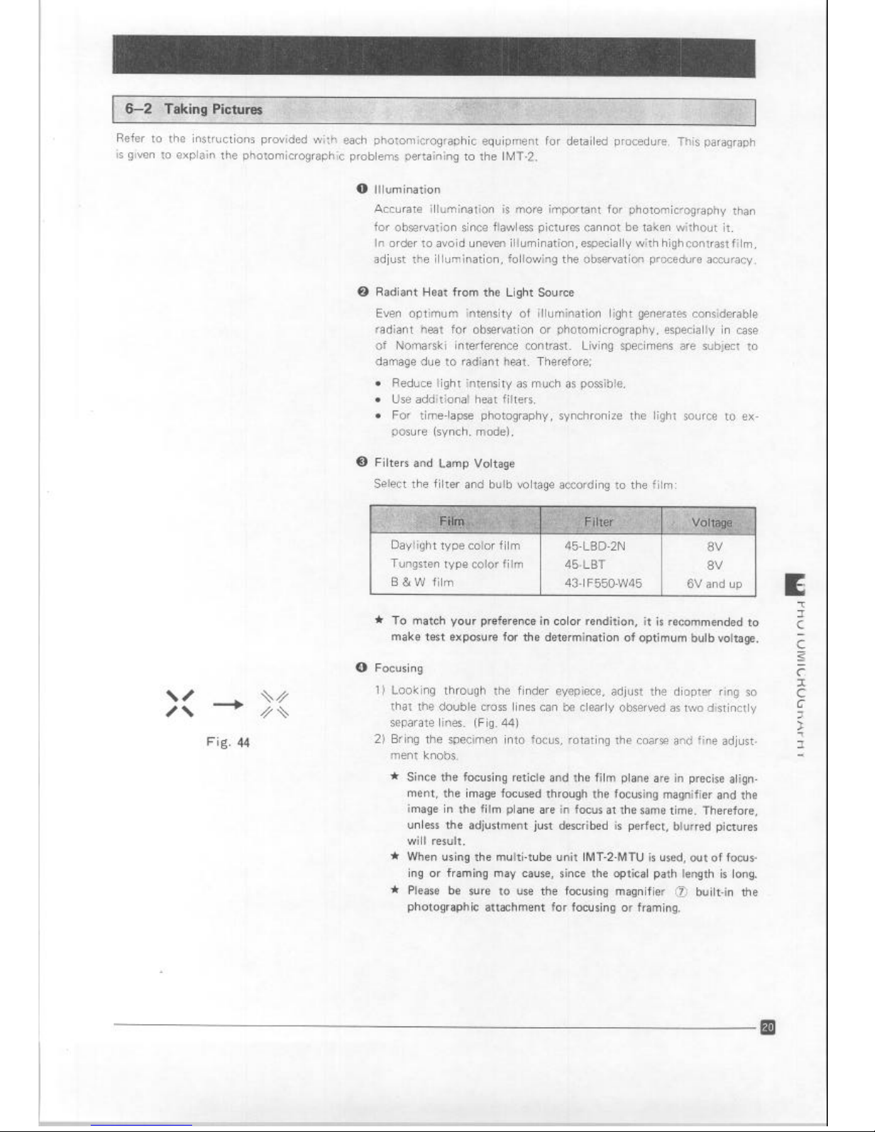
0 Focusing
\/
x - //\
Fig. 44
1) Looking through the finder eyepiece, adjust the diopter ring so
that the double cross lines can be clearly observed as two distinctly
separate lines. (Fig. 44)
2) Bring the specimen into focus, rotating the coarse and fine adjustment knobs.
* Since the focusing reticle and the film plane are in precise align-
ment, the image focused through the focusing magnifier and the
image in the film plane are in focus at the same time. Therefore,
unless the adjustment just described is perfect, blurred pictures
will result.
* When using the multi-tube unit IMT-2-MTU is used, out of focus-
ing or framing may cause, since the optical path length is long.
* Please be sure to use the focusing magnifier @ built-in the
photographic attachment for focusing or framing.
Artisan Technology Group - Quality Instrumentation ... Guaranteed | (888) 88-SOURCE | www.artisantg.com
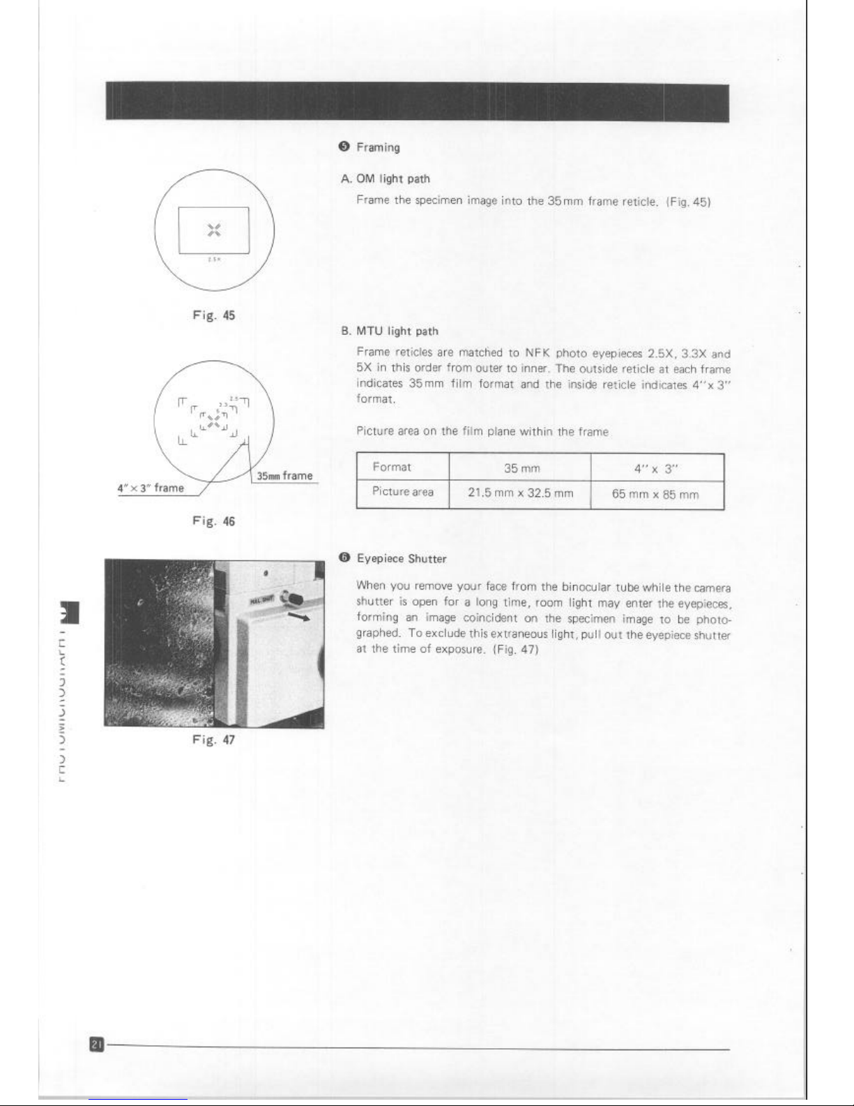
@ Framing
Fig. 45
4” x 3”
frame
Fig. 46
Fig. 47
A.
OM light path
Frame
the specimen image into the 35mm frame reticle. (Fig. 45)
B. MTU light path
Frame retitles are matctied to NFK photo eyepieces 2.5X. 3.3X and
5X in this order from outer to inner. The outside reticle at each frame
indicates 35mm film format and the inside reticle indicates 4”~ 3”
format.
Picture area on the film plane within the frame
Format
35 mm
4” x 3”
Picture area
21.5 mm x 32.5 mm
65mmx85mm
@ Eyepiece Shutter
When you remove your face from the binocular tube while the camera
shutter is open for a long time, room light may enter the eyepieces,
forming an image coincident on the specimen image to be photographed. To exclude this extraneous light, pull out the eyepiece shutter
at the time of exposure. (Fig. 47)
Artisan Technology Group - Quality Instrumentation ... Guaranteed | (888) 88-SOURCE | www.artisantg.com

If you are unable to obtain optimum performance from your microscope, please consult the table below for
trouble shooting.
1. Optical system
a) Switching on light source, field Bulb socket cord is not connected.
Connect the cord to receptacle on
of view is still dark. the microscope stand.
Bulb is burned out. Replace.
Sliding voltage control lever is set at Set it at higher voltage position.
to0
low a position.
Bulb is not centered.
Center it.
Condenser holder is not clamped in
Clamp it.
place.
Condenser is not in correct position.
Adjust condenser height until field
diaphragm image is formed in specimen plane.
Condenser is not centered.
Center it until field diaphragm
image comes in the center.
Nosepiece is not clicked in place.
Rotate it slightly until it clicks in
place.
Light path selector knob is at the
Set knob to the BI position or in-
OM or MTU position. crease bulb voltage.
Too many filters are engaged.
Reduce number of filters.
Stage insert plate blocks light path.
Remove stage and reset specimen.
Fuse is burned out.
Check electric circuit and after removal of cause, replace fuse.
Line voltage selector switch is not Adjust switch correctly.
set to conform with local mains
voltage.
b) Field of view is cut off at the Light path selector knob is stopped Click knob into place according to
periphery or illuminated uneven-
midway.
purpose.
IY.
Nosepiece and magnification
Click them into place.
changer are not positioned correct-
ly.
Condenser turret is not correctly
Click turret into place.
Condenser is not positioned or Click condenser turret Into place or
centered correctly. center correctly.
Light source is not centered.
Center light source.
Filter is stopped midway. Pull or push it completely.
c) Dust or dirt is visible in field of
Dirty specimen.
Clean slide or culture vessel.
view.
Dust on eyepiece.
Clean eyepiece.
Condenser is not correctly posi- Adjust condenser height until field
tioned and the frosted filter is in diaphragm image is formed on spe-
focus. cimen plane.
positioned.
Artisan Technology Group - Quality Instrumentation ... Guaranteed | (888) 88-SOURCE | www.artisantg.com

1) Excessive image contrast.
Condenser is stopped in high posi-
Lower condenser.
tion.
Aperture diaphragm is stopped Open diaphragm.
down excessively.
?) Resolution problems: Objective is not correctly posi- Click nosepiece into place.
l
Image is not sharp. tioned in light path.
0 Insufficient contrast.
l
Image details lack definition.
Aperture diaphragm is stopped
Adjust aperture iris opening prodown excessively or opened too perly.
much.
Correction collar is not adjusted
Looking at specimen image, rotate
correctly.
correction collar until optimum
focusing position can be found.
Dust on condenser, objective, eye- Clean.
piece, culture vessel, etc.
Thickness of vessel bottom is more
Use a vessel of bottom thickness
than 2 mm.
less than 2 mm.
‘) No effective phase contrast is Bright field objective is used.
Use phase objective.
obtained.
Light annulus is not matched with Match light annulus to objective.
objective.
Light annulus and phase annulus Center them correctly.
are not centered.
g) Specimen image is partially out Objective is not correctly in light Slightly rotate nosepiece until it
of focus. path. clicks into place.
Specimen is not correctly place on
Place specimen correctly.
stage.
Vessel bottom is not flat. Use an evenly-flat bottomed vessel.
h) Image is blurred. Condenser is not correctly centered.
Center condenser.
Light source is not correctly cen-
Center light source correctly,
tered.
Condenser holder is tilted up. Lower it to stop position.
2. Electrical adjustment
a) Light source is too bright even at
Minimum line voltage adjustment
Adjust the knob until bulb is dimly
lowest bulb voltage. knob is not correctly adjusted.
lit with sliding control lever at
lowest position (nearest to you).
b) Light flickers and intensity is un-
Line voltage is unstable.
Use voltage stabilizer.
stable.
Bulb filament is likely to burn out. , Replace bulb.
Loose electrical connection.
I
i Tighten connections.
c) Fuse burns out too often.
Fuse is not a standard one. 1 Use standard fuse.
8
RI Ilh
is nnt stnnrinrri
i I ICD
hzlnnon hi,lh
rlarinnotorl
d) Pilot
bulb
is tur
Artisan Technology Group - Quality Instrumentation ... Guaranteed | (888) 88-SOURCE | www.artisantg.com
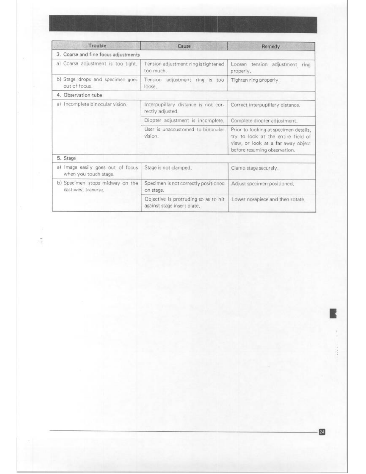
3. Coarse and fine focus adjustments
a) Coarse adjustment is too tight. Tension adjustment ring is tightened
Loosen tension adjustment ring
too much.
properly.
b) Stage drops and specimen goes
Tension adjustment ring is too Tighten ring properly.
out of focus. loose.
4. Observation tube
a) Incomplete binocular vision. lnterpupillary distance is not cor-
Correct interpupillary distance.
rectly adjusted.
Diopter adjustment is incomplete. Complete diopter adjustment.
User is unaccustomed to binocular
Prior to looking at specimen details,
vision.
try to look at the entire field of
view, or look at a far away object
before resuming observation.
5. Stage
a) Image easily goes out of focus
Stage is not clamped. Clamp stage securely.
when you touch stage.
b) Specimen stops midway on the Specimen is not correctly positioned
Adjust specimen positioned.
east-west traverse. on stage.
Objective is protruding so as to hit Lower nosepiece and then rotate.
against stage insert plate.
Artisan Technology Group - Quality Instrumentation ... Guaranteed | (888) 88-SOURCE | www.artisantg.com

OLYMPUS OPTICAL CO., LTD.
San-Ei Building, 22-2, Nishi Shinjuku 1-chome, Shinjukuku, Tokyo, Japan
OLYMRUS OPTlCAL CO., (EUROPA) GMBH.
Postfach 104908, Wendenstrasse 14-16, 2000 Hamburg 1, Germany
OLYMPUS CORPORATION
4 Nevada Drive, Lake Success, N.Y. 11042-l 179, U.S.A.
OLYMPUS OPTICAL CO. (U.K.) LTD.
2-8 Honduras Street, London EClYOTX, United Kingdom
J
The design of the product IS under constant
review and whilst every effort is
made to keep this manual up to date, the rtght IS reserved to change speciflca-
tions and equipment at any time wthout prior notice
Printed in
J~DX 9011 M 04
Artisan Technology Group - Quality Instrumentation ... Guaranteed | (888) 88-SOURCE | www.artisantg.com

Artisan Technology Group is your source for quality
new and certied-used/pre-owned equipment
• FAST SHIPPING AND
DELIVERY
• TENS OF THOUSANDS OF
IN-STOCK ITEMS
• EQUIPMENT DEMOS
• HUNDREDS OF
MANUFACTURERS
SUPPORTED
• LEASING/MONTHLY
RENTALS
• ITAR CERTIFIED
SECURE ASSET SOLUTIONS
SERVICE CENTER REPAIRS
Experienced engineers and technicians on staff
at our full-service, in-house repair center
WE BUY USED EQUIPMENT
Sell your excess, underutilized, and idle used equipment
We also offer credit for buy-backs and trade-ins
www.artisantg.com/WeBuyEquipment
REMOTE INSPECTION
Remotely inspect equipment before purchasing with
our interactive website at www.instraview.com
LOOKING FOR MORE INFORMATION?
Visit us on the web at www.artisantg.com for more
information on price quotations, drivers, technical
specications, manuals, and documentation
Contact us: (888) 88-SOURCE | sales@artisantg.com | www.artisantg.com
SM
View
Instra
 Loading...