

Page 1

®
USER INSTRUCTIONS
MITICO(-2L)
LAS-BOB
LAS-MC
MOTORIZED INTEGRATED TIRF
ILLUMINATION COMBINER
LASER SAFETY BREAK-OUT BOX
LASER MANUAL CONTROL
This instruction manual describes the Olympus MITICO illumination combiner with
accessories. To ensure safety, obtain optimum performance and familiarize yourself fully with the
use of this product, we recommend that you study this manual thoroughly before operation.
Together with this manual, please also read the imaging system manuals, the laser manual and
the instruction manual of the microscope in order to understand overall operation methods.
Retain this manual in an easily accessible place near a system for future reference.
Page 2

OLYMPUS SOFT IMAGING SOLUTIONS GMBH
Johann-Krane-Weg 39
D-48149 Münster
Tel: +49 89 - 89 55 805 660
Fax +49 89 - 89 55 805 6606
Email: info@olympus-sis.com
www.olympus-sis.com
Page 3

Imaging Excellence
We at Olympus Soft Imaging Solutions GmbH have tried to make the information in this manual as
accurate and reliable as possible. Nevertheless, Olympus Soft Imaging Solutions GmbH disclaims any
warranty of any kind, whether expressed or implied, as to any matter whatsoever relating to this manual, including without limitation the merchantability or fitness for any particular purpose. Olympus Soft
Imaging Solutions GmbH will from time to time revise the software described in this manual and reserves the right to make such changes without obligation to notify the purchaser. In no event shall
Olympus Soft Imaging Solutions GmbH be liable for any indirect, special, incidental, or consequential
damages arising out of purchase or use of this manual or the information contained therein.
No part of this document may be reproduced or transmitted in any form or by any means, electronic or
mechanical, for any purpose, without the prior permission of Olympus Soft Imaging Solutions GmbH.
2010 by Olympus Soft Imaging Solutions GmbH. All rights reserved.
Manual version: September 2010
Page 4

Page 5

Illumination Combiner, User Manual Contents
Contents
1
Introduction ................................................................................................. 1
1.1 Abstract ........................................................................................................ 2
1.2 General ......................................................................................................... 2
1.3 Components .................................................................................................3
2
Safety Symbols............................................................................................5
3
Safety Precautions and Handling Instructions .......................................9
3.1 Laser Safety Precautions ............................................................................10
3.2 General Safety Precautions ........................................................................11
4
4.1 Setup Scheme ............................................................................................14
4.2 The Laser Safety Features .......................................................................... 15
4.3 The MITICO Features – an Overview .......................................................... 17
4.4 The LAS-BOB Laser Safety Break-out Box ................................................18
4.5 The Laser Shutter Manual Control..............................................................18
4.6 The AD-USB-ODB Bus Adaptor Box.......................................................... 19
4.7 The Remote Interlock Connector of the Olympus ..........................................
Soft Imaging Solutions ODB Laser Systems ..............................................20
4.8 The Light Path Selector Slider ....................................................................20
4.9 The Iris Diaphragm Field Stops .................................................................. 21
4.10 Laser Clean-up Filter Sliders ...................................................................... 22
4.11 Focusing the Laser Lines............................................................................22
4.12 The FRAP Lens of Laser Line 1 .................................................................. 23
4.13 Laser Adjustment........................................................................................23
4.14 Filters, Mirrors, Objectives .......................................................................... 24
MITICO and Peripherals Overview..........................................13
5
Modes of Operation .................................................................................. 25
5.1 The User Mode ...........................................................................................26
5.2 The Maintenance Mode .............................................................................. 27
5.2.1 Exchanging Microscope or Camera Hardware .........................................28
5.2.2 Adjusting the Laser Beam Position ...........................................................28
5.2.3 Access to the Specimen without Deactivating the TIRFM System .......... 28
5.2.4 Observing the Specimen under TIRF Illumination Through the Ocular ....29
6
Using the MITICO Illumination Combiner ............................... 31
6.1 The cell^TIRF Control Software.................................................................. 32
6.2
6.2.1 System Configuration ............................................................................... 38
6.2.2 Operating MITICO ...................................................................... 39
6.2.3 TIRFM in the Experiment Manager ...........................................................41
7
Specifications and Technical Data.......................................................... 45
MITICO Control via the cell^R Software ..................................... 38
Page 6

Page 7

Illumination Combiner, User Manual Chapter 1 –Introduction 1
1 Introduction
Thank you very much for purchasing Olympus Soft Imaging Solutions' state of art motorized
illuminator system, and for your confidence in our products and service. It is Olympus Soft Imaging
Solutions' main objective to provide you with solutions able to meet your experimental demands and
thus pave the way to your scientific success.
The
lasers and a white-light source to an inverted Olympus IX2 microscope and to adjust the position of
each laser beam individually relative to the optical axis to obtain total internal reflection illumination.
illuminator system is designed for general laboratory use only. It allows coupling up to four
1.1 Abstract ........................................................................................................ 2
1.2 General ......................................................................................................... 2
1.3 Components .................................................................................................3
Page 8
2 Chapter 1 – Introduction
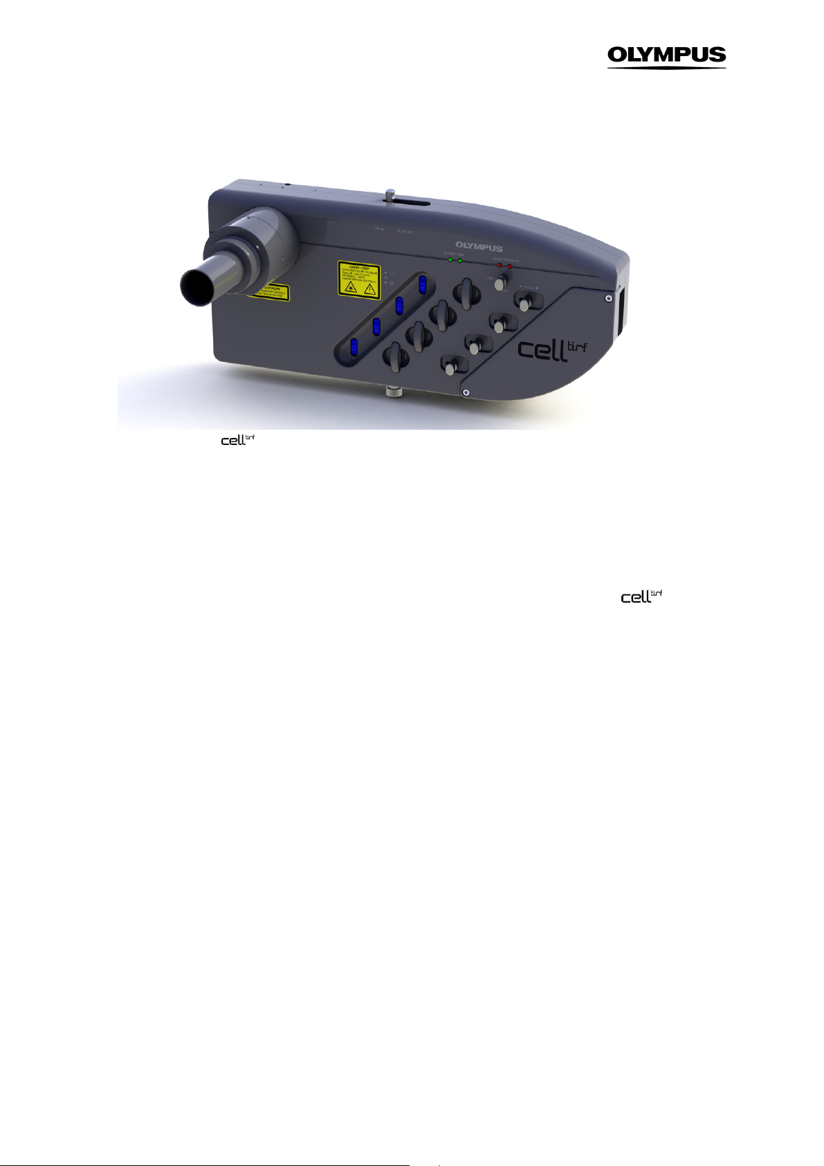
Motorized multi-port
illumination combiner MITICO with fiber port for widefield illumination
1.1 Abstract
In the following sections you will find a detailed description of the components of the
system, handling and alignment instructions and how to maintain the performance of your TIRF microscope. Keep in mind that all components are designed to work together with an Imaging Station like
the Olympus cell^M or cell^R as an integrated system. We strongly discourage taking away or replacing single components without prior consultation of Olympus Soft Imaging Solutions, most probably it
will impair the performance of the system dramatically. The guarantee will not cover any damages to
the system due to such mishandling. All necessary tools for handling and alignment (except the laser
safety goggles) are part of the product.
If you find any information missing in this manual or you need additional support, please contact your
local Olympus representative.
illuminator
1.2 General
The MITICO motorized integrated TIRF illumination combiner is compatible with the Olympus microscopes IX51, IX71 and IX81 as well as a range of laser systems within visible spectral range between
400nm and 700nm provided that they meet the following requirements:
• Every laser unit must have an input remote-control safety interlock that must be connected to the
central laser emergency stop and which interrupts the laser radiation in case of danger (EN 60825-
Page 9

Illumination Combiner, User Manual Chapter 1 –Introduction 3
1:2003, Sect. 4.4 and 10.2). Furthermore, every laser unit must have a key-activated main power
switch in the sense of EN 60825-1:2003, Sect. 4.5).
• Provided that the laser units can be operated independently they must have their own emission
warning display (audible or visible) (EN 60825-1:2003, Sect. 4.6).
• The combined power of all employed and/or connected laser powers must not exceed 500mW.
This instructions manual describes the hardware components of the
illuminator system, their
installation and alignment. For the use of the connected lasers refer to the respective manuals.
It is important to familiarize yourself with the entire system to ensure safety and optimum performance.
We recommend studying this manual as well as the software and hardware manuals of the imaging
system thoroughly before operating the
illuminator system. Keep this manual close to the imag-
ing station for future reference.
The
illuminator system meets the CE requirements:
• EN61326 Class A
• EN60825
1.3 Components
The TIRF illuminator system consists of the following hardware components:
a MITICO motorized integrated TIRF illumination combiner:
—
Four fiber ports, each with adjustable line focus
—
A port for either a TIR-LHA adaptor to couple a standard fluorescence lamp housing or TIRMTCON to couple a MT10 / MT20 illumination system.
—
A slider to switch between 100% widefield illumination and 50% widefield plus 100% TIRF
—
Motorized drives to move each laser line
—
A field stop for each laser line
—
Removable slider for a clean-up filter for each laser line
—
FRAP focus lens for the first line that can be moved in and out of the optical path
—
Laser safety shutter with key
—
Illumination combiner support
b Laser shutter hand switch LAS-MC with key with emergency interrupter and key-controlled switch
to maintenance mode
c Laser safety break-out box LAS-BOB
d Laser safety stage cover with translucent laser safety glass that allows following the beam position
e Laser safety ocular shutter
f Laser beam alignment tool
g Manuals
The following items are additionally needed to convert a fluorescence microscope into a TIRF microscope:
h Up to four laser systems with a maximum total of 500 mW light output
Page 10

4 Chapter 1 – Introduction
i – Either a TIR-LHA adaptor to couple a standard fluorescence lamp housing
– or a TIRMT-CON to couple a MT10 / MT20 illumination system
j A widefield illumination system
– Either a standard fluorescence lamp housing, e.g., U-LH100HGAPO
– or a MT10 / MT20 illumination system
Page 11

Illumination Combiner, User Manual Chapter 2 –
Safety Symbols
5
2 Safety Symbols
The deactivation of the safety systems or the dismantling of different components by the operator is
required in certain operational modes and in case of illumination alignment. As a result the Olympus
motorized
safety class 3B and in accordance to EN 954-1:1997 in hazard category 2. Class 3B lasers are medium power lasers with an output power of up to 500 mW within 400 – 700 nm wavelength. Laser
safety regulations require extensive labeling of all possible apertures where laser radiation might potentially exit including such apertures that are totally covered except upon partially or totally disassembling
the system.
illuminator system is to be classified in accordance with EN 60825-1:2003 in laser
Page 12
6 Chapter 2 –
Safety Symbols
The following symbols are placed on the Olympus
illuminator system. Study the meaning of the
symbols and always use the equipment in the safest possible manner.
General symbols
Symbol Explanation
Indicates the use of a laser beam. Take special care in handling that part.
(See also following chapter)
Carefully read the instructions on the label and the manual before use. Improper use could
result in personal injury to the user and/or damage the equipment.
This symbol indicates separate collection of waste electrical and electronic equipment in the EU
countries.
Do not throw the equipment into the domestic refuse
Please use the return and collection systems available in your country for the disposal of this
product
Each laser source must be provided with a danger symbol, a sign with the classification text and a sign
on the beam exit opening. Please ensure that your microscope is labeled as shown in the table below.
For all parts labeled with the following labels special laser precautions must be considered (see Chapter 4.1, Laser Safety Precautions)!
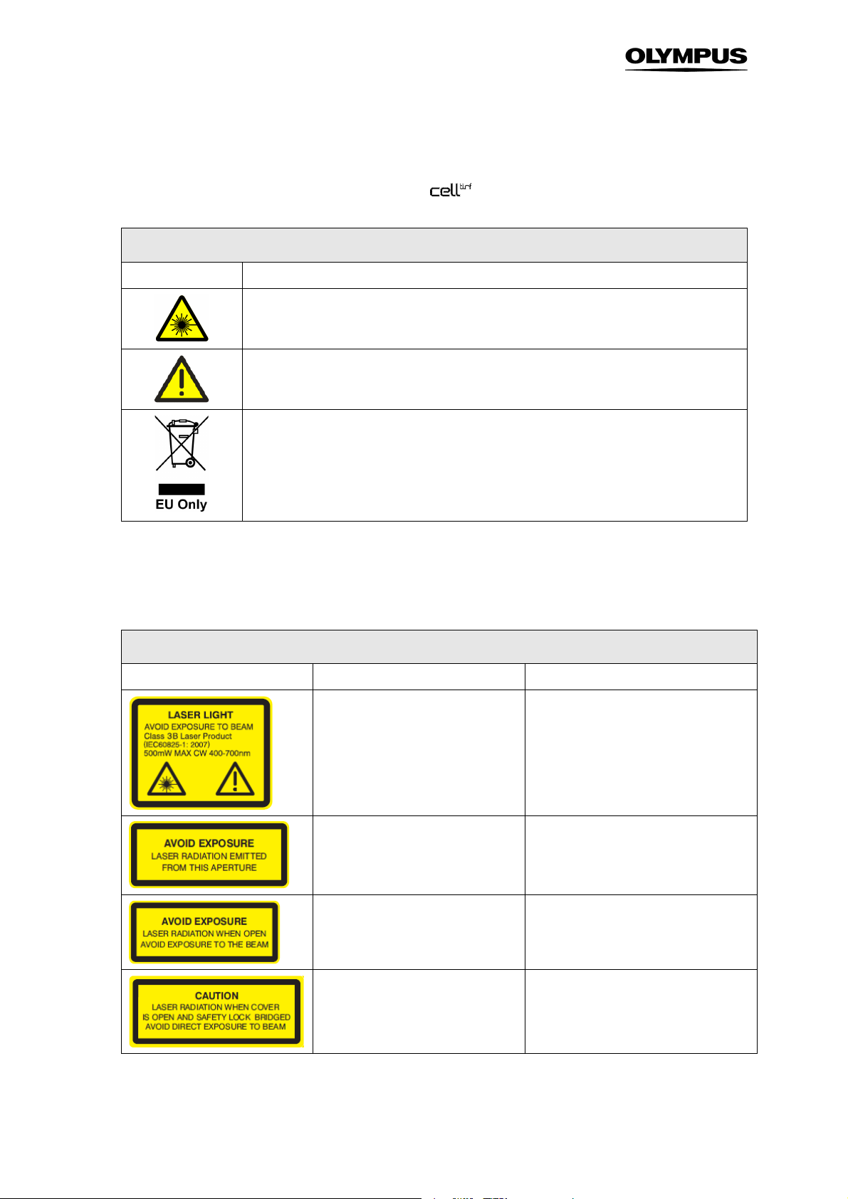
Laser safety symbols
Symbol Explanation Location
Indicates the use of a laser beam.
Take special care in handling this part.
Front of the MITICO illumination combiner; see photos 1
Laser radiation can cause irreversible
damage to your eyes. Wear adequate
protection before opening this aperture.
These apertures should be closed
while operating the system. Parts
connected should be dismounted by
trained personal only and when the
laser is turned off.
When system is switched to maintenance mode laser radiation can be
emitted from this aperture. Be sure to
wear adequate eye protection.
Front of the MITICO illumination combiner. May be hidden if the MITICO is
mounted on the microscope; see photo 1.
Microscope frame, right side, left side
near C-mount; see photos 2 and 3.
Laser safety ocular shutter; see photo 4.
Laser safety stage cover; see photo 5.
Page 13
Illumination Combiner, User Manual Chapter 2 –
Safety Symbols
7
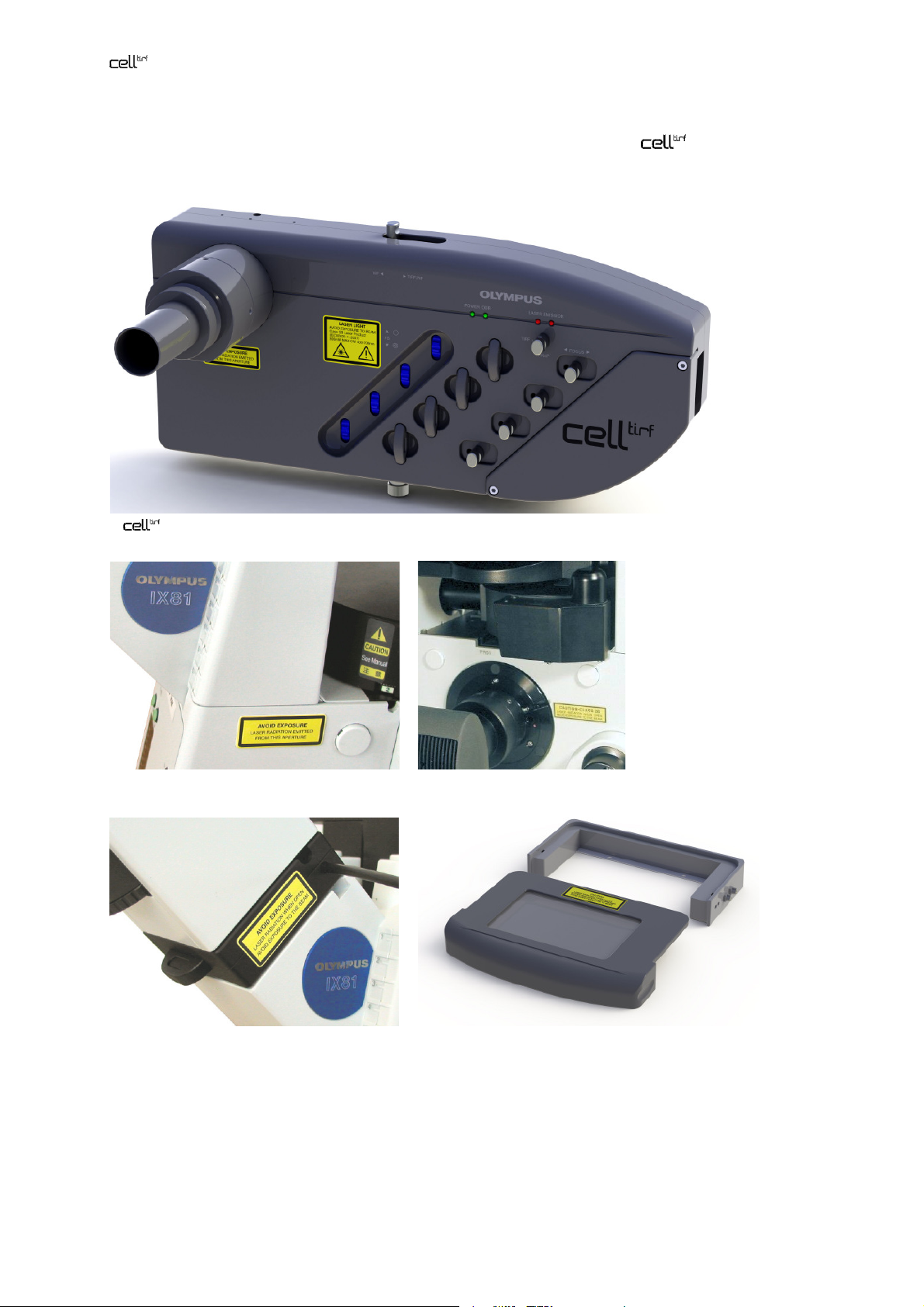
Labels for the microscope components are included in the shipping list of the
illuminator system. Please paste them on the microscope upon system installation. If any label is missing please ask
your Olympus representative for additional labels.
1:
MITICO motorized integrated TIRF illumination combiner
2: microscope frame, right side 3: fluorescence turret and C-mount
4: laser safety ocular shutter 5: laser safety stage cover
Page 14

8 Chapter 2 –
Safety Symbols
Page 15

Illumination Combiner, User Manual Chapter 3 – Safety Precautions and Handling Instructions 9
3 Safety Precautions and Handling
Instructions
The Olympus
Class 3B. Class 3B lasers are medium power lasers with an output power of up to 500 mW within 400 –
700 nm wavelength. The total of the output power of the connected lasers may not exceed 500 mW.
Viewing these lasers under direct beam and specular reflection conditions is hazardous. The diffuse
reflection is usually not a hazard except for higher power Class 3B and Class 4 lasers. Normally the
class 3B laser is not a fire hazard. A class 3B laser product may only be used under the control of a
laser safety officer. Before using this product be sure to be familiar with the demanded safety measures
according to EN 60825-1 and the national regulations
illuminator system must be used with laser products belonging to the Laser Safety
3.1 Laser Safety Precautions ............................................................................10
3.2 General Safety Precautions ........................................................................11
Page 16

10 Chapter 3 – Safety Precautions and Handling Instructions
3.1 Laser Safety Precautions
Caution: Control or adjustments using procedures other than those prescribed in this manual will lead to hazardous laser beam exposure.
To avoid hazardous situations strictly follow the laser safety instructions below.
1. Before operating an Olympus
rectly and all apertures are closed.
2. The usage of a Class 3B laser is only permitted under the control of a laser safety officer.
3. A Class 3B laser can cause irreversible damage to your eyes. Thus do not stare into the
laser beam or illuminated fiber. Make sure to wear adequate eye protection during operation
of the laser in maintenance mode.
4. Always operate the
training in operating the system in maintenance mode. Inform your laser safety officer if you
intend to operate the system in maintenance mode. The user mode is the safest manner to
operate the system. Opening the stage cover or the binocular slider will interrupt the laser
beam in this mode.
5. Only trained Olympus service personnel is allowed to perform the installation and alignment
procedures described in the Service Manual.
6. A person in charge with the laser alignment or performing scientific experiments while oper-
ating the laser in maintenance mode must be aware of the safety precautions adequate to
the TIRF microscope setup. He/she is responsible for the safety of any person present in the
room while operating the lasers in maintenance mode.
illuminator system in user mode unless you underwent a detailed
illuminator system check if all devices are attached cor-
7. The focused laser beam or any UV light emitted from the microscope nosepiece may injure
the skin through the objective exit lens and through a free nosepiece position. Thus, avoid
exposing the hands to the laser beam when working on the microscope.
8. Do not bend, step on or pull excessively on the laser fibers. This could damage a fiber and
cause hazardous beam leakage. In case of a damaged fiber, switch off the laser immediately
and contact Olympus.
9. Be sure all apertures of your microscope system stay closed or are connected while operat-
ing the laser. A change in camera or any microscope part should be performed only when
the laser is turned off.
10. Never cover the air outlet of the laser to prevent overheating.
Page 17

Illumination Combiner, User Manual Chapter 3 – Safety Precautions and Handling Instructions 11
Direct exposure to the laser light is possible at the following positions:
• The laser system’s housing at the fiber port if the fiber is removed
• The exit of the laser fiber
• The fiber coupling of the widefield illumination system to the
• The beam path of the microscope
• Any microscope port, which includes the entrance ports because the laser light can be reflected
within the microscope
• The light output port of the widefield illumination system
• The objective tip or – if no objective is mounted – a free nose piece position
illuminator system
3.2 General Safety Precautions
a Always use power cords and power supplies provided or approved by Olympus Soft Imaging Solu-
tions or the manufacturer of your laser system.
b Provide unimpaired access to the emergency shutter switch at the LAS-MC manual control and to
the main power switches.
c Only those lasers may be connected that comply the laser safety regulations as described in Chap-
ter 1.2.
d Always make sure that the grounding terminal of the laser system and the wall outlet are connected
properly. If the system is not grounded, Olympus Soft Imaging Solutions cannot warrant the electrical safety and proper performance of the product.
e Please refer to the user manuals of the respective laser manufacturer for adequate safety precau-
tions and proper usage.
f If the equipment is not used as specified in this manual, the safety and performance may be im-
paired. In addition the equipment may be damaged and warranty may be lost. Use the equipment
only as outlined in this instruction manual.
Olympus Soft Imaging Solutions GmbH accepts no liability for any health damages caused
by improper use of the lasers and laser related setup!
Page 18

12 Chapter 3 – Safety Precautions and Handling Instructions
Page 19

Illumination Combiner, User Manual Chapter 4 –
MITICO and Peripherals Overview 13
4
MITICO and Peripherals
Overview
The following chapter describes all components and interfaces of the Olympus
tem including all laser safety devices.
4.1 Setup Scheme ............................................................................................14
4.2 The Laser Safety Features .......................................................................... 15
4.3 The MITICO Features – an Overview .......................................................... 17
4.4 The LAS-BOB Laser Safety Break-out Box ................................................18
4.5 The Laser Shutter Manual Control..............................................................18
4.6 The AD-USB-ODB Bus Adaptor Box.......................................................... 19
4.7 The Remote Interlock Connector of the Olympus ..........................................
Soft Imaging Solutions ODB Laser Systems ..............................................20
4.8 The Light Path Selector Slider ....................................................................20
4.9 The Iris Diaphragm Field Stops .................................................................. 21
4.10 Laser Clean-up Filter Sliders ...................................................................... 22
4.11 Focusing the Laser Lines............................................................................22
4.12 The FRAP Lens of Laser Line 1 .................................................................. 23
4.13 Laser Adjustment........................................................................................23
4.14 Filters, Mirrors, Objectives .......................................................................... 24
illuminator sys-
Page 20

14 Chapter 4 –
top view
Laser fibers
MITICO and Peripherals Overview
4.1 Setup Scheme
To MT20 illumi-
nation system
Laser safety
shutter inside
TIRMT-CON
MITICO
Laser safety
stage cover
Laser safety
ocular shutter
IX81,
To real-time control-
ler or USB adaptor
LASBOB
TIRF lasers with
safety shutters
LAS-MC laser shutter manual
control with emergency interrupter and key control
Scheme of an IX81 microscope with a
lasers and the laser safety equipment .
Connections of the laser safety devices
ODB communication connections
TTL trigger connections to switch the functional laser shutters via LAS-MC
MT20 light fiber
Laser fibers
MITICO
illumination combiner with widefield illuminator TIRMT-CON, four
Page 21

Laser
safety
Illumination Combiner, User Manual Chapter 4 –
4.2 The Laser Safety Features
MITICO and Peripherals Overview 15
The laser safety concept of the
—
A double-redundant laser safety shutter in front of the exit optics of the
illuminator system consists of the following modules:
combiner
—
A laser safety ocular shutter
—
A laser safety stage cover
—
An emergency interrupter located on the LAS-MC manual control
—
The double-redundant laser safety shutter of Olympus laser systems
—
The LAS-BOB laser safety break-out box that connects all devices electronically
Be sure that all listed components are correctly mounted:
• The laser safety ocular shutter must be placed in the ocular light path as shown below.
ocular shutter
illumination
• The U-shaped frame of the laser safety stage cover must be fixed on the stage and the stage cover
in place.
The laser safety stage cover must be secured to the microscope stage. If the microscope
stage is not equipped with the necessary pre-drilled holes please make sure that this modification is performed before using the system. Appendix –Laser Safety Stage Cover Dimensions in the Service Manual provides drawings with all dimension data necessary
for such a modification.
Page 22

16 Chapter 4 –
Laser safety
frame
Laser safety
MITICO and Peripherals Overview
stage cover
stage cover
• The 5-pin ocular shutter cable must be connected to the stage cover and this additionally to the 5-
pin STAGE COVER plug of LAS-BOB laser safety breakout box.
• One of the two SAFETY SHUTTER plugs of the LAS-BOB laser safety break-out box must be con-
nected with the laser safety shutter plug on the electronics housing on the back side of the MITICO
illumination combiner using the 4-pin cable.
Check the safety shutter function in user mode in a completely installed TIRFM system.
1. Turn the key in the LAS-MC manual control to USER MODE.
2. Set the REMOTE switch of the LAS-MC manual control to 0.
3. Open the shutter of one of the connected lasers with the corresponding LASER switch on
the LAS-MC manual control. You should observe laser light through the translucent stage
cover insert.
4. Open the ocular shutter slider. The indicator diode on the laser safety shutter must become
switched off immediately indicating the closure of the shutter. No laser light should be visible
anymore. Close the slider again.
5. Carefully lift the lid of the stage cover. The indicator diode on the laser safety shutter must
become switched off immediately indicating the closure of the shutter. No laser light should
be visible anymore. Mount the cover again.
The LAS-MC manual control features an emergency interrupter, the red button. If the system is properly setup and you press the red button,
• The safety shutter of any Olympus Soft Imaging Solutions laser system connected must close
• Any other laser connected to the LAS-BOB break-out box must be switched off entirely
• The safety shutter of the MITICO illumination combiner must close.
In order to reactivate the system you have to turn the emergency interrupter to release it from the
locked position.
Applying the laser safety emergency interrupter is not a standard test and should only be
tested if changes to the laser configuration and connections have been made. It is only for
emergency use and will cut the power supply of any laser except the Olympus Soft Imaging
Solutions laser systems.
If you have doubts or questions concerning your laser safety devices, contact your laser safety officer.
Page 23

Spacer for sta
n
dard
Spacer removed
Illumination Combiner, User Manual Chapter 4 –
4.3 The MITICO Features – an Overview
The MITICO motorized integrated TIRF illumination combiner features
—
Four FCP8/FCP laser fiber ports with four-axis alignment
—
Two Lemo plugs to connect it via ODB communication cables with
a) – either the real-time controller inside the PC of a cell^M / cell^R imaging system
– or the AD-USB-ODB bus adaptor box and
b) other OSIS ODB devices (in daisy chain)
—
A 5-pin plug to connect with the SAFETY SHUTTER plug of the LAS-BOB laser safety breakout box
—
Two red safety shutter status diodes
—
A green ODB communication status diode
—
A green power status diode
—
An iris diaphragm field stop for each laser line
—
A laser clean-up filter slider for each laser line
—
A laser beam focus slider for each laser line
—
A switch to insert a FRAP focusing lens into the beam path of line 1
—
A light path selector slider to switch from 100%TIRF with 50% widefield illumination to 100%
widefield illumination
—
A widefield fluorescence illumination port to mount
a) either a TIRMT-CON widefield fiber illumination coupling if a fiber-coupled fluorescence illumination systems MT10 or MT20 is to be used or
b) a TIR-LHA adaptor if a standard fluorescence lamp housing is to be used
MITICO and Peripherals Overview 17
—
An epi-fluorescence illuminator tube to connect it with the microscope frame. This contains a
spacer unit with tube, which has to be removed for ZDC-equipped microscopes.
microscope frames
for ZDC frames
Page 24

18 Chapter 4 –
MITICO and Peripherals Overview
4.4 The LAS-BOB Laser Safety Break-out Box
It features on the front panel
—
Four INTERLOCK 4 – 3 – 2 – 1 cinch plugs to connect it with the INTERLOCK connectors of
Olympus Soft Imaging Solutions laser systems (Other lasers may need adaptors.)
—
Four SHUTTER 4 – 3 – 2 – 1 BNC TTL-OUT plugs to connect with TTL-IN ports of Olympus
Soft Imaging Solutions laser systems or laser shutters like the LAS-SHU-PSFIB.
—
A LAS-MC D-sub 15-pin female plug to connect with the laser shutter manual control
and on the back panel
—
Two SAFETY SHUTTER 4-pin female plugs one of which is to be connected with the corresponding plug on the MITICO illuminator
—
Four DIGITAL I/O 1 – 2 – 3 – 4 BNC TTL-IN plugs to connect with shutter control TTL-OUT
ports of a control unit, for example the cell^M / cell^R real-time controller in case that no laser
systems by Olympus Soft Imaging Solutions are used
—
A STAGE COVER 4-pin female plug to connect with the laser safety stage cover
ÈÈÈÈ
—
A 24 V ÿÿÿÿ–
rrrr
-C•-
DC power supply plug to connect with 24 V DC power supply.
4.5 The Laser Shutter Manual Control
The laser shutter manual control features
—
A D-sub 15-pin female plug to connect with the LAS-MC plug of the LAS-BOB break-out box
—
Four LASER 1, 2, 3, 4 switches to open and close each high-speed laser shutter individually
—
A REMOTE switch to set the shutters to remote control via external TTL triggers or ODB device bus communication (typically controlled by a software like cell^M / cell^R)
—
A mode lock with key to allow authorized and trained personnel to switch from standard USER
MODE to MAINTENANCE (see Chapter 5, Modes of Operation).
—
A red emergency interrupter that close all safety shutters when pressed
Page 25

Switches for up to four TTL
-
Button to
Mode lock
with key
Emergency
Switch to toggle between sof
t
ware control
Illumination Combiner, User Manual Chapter 4 –
—
bridge laser
safety ocular
shutter
MITICO and Peripherals Overview 19
A BINOCULAR button to bridge the laser safety ocular shutter in maintenance mode so that
the specimen can be observed via ocular with laser illumination. This is not a toggle button; it
needs to be kept pressed in order to keep the laser safety shutter open.
Be extremely cautious when bridging the laser safety ocular shutter by pressing the red
button! Be sure that a filter cube that quantitatively blocks reflected laser light is inserted
into the light path. Otherwise hazardous and intense laser light might exit the ocular. Set
the laser to a low intensity with the attenuator before first looking through the ocular.
and hand switch control of TTL laser shutters
interrupter
controlled high-speed laser
shutters
4.6 The AD-USB-ODB Bus Adaptor Box
It is needed for non-cell^M / cell^R systems only and features on the front panel:
—
A power On/Off switch.
—
A green Power On diode
—
An orange ODB communication status diode
and on the back panel:
—
—
—
An ODB plug to connect it via ODB communication cables with the MITICO illuminator
A USB Type-B plug to connect it with the imaging PC via a USB Type-A-to-Type-B cable
ÈÈÈÈ
A 24 V ÿÿÿÿ–
rrrr
-C•-
DC power supply plug to connect with 24 V DC power supply.
Page 26

20 Chapter 4 –
MITICO and Peripherals Overview
4.7 The Remote Interlock Connector of the Olympus
Soft Imaging Solutions ODB Laser Systems
An INTERLOCK connector can be found at the front panel of all Olympus Soft Imaging Solutions laser
systems as Class 3B laser products. This remote interlock connector must be connected to the emergency interrupter of the system via the corresponding INTERLOCK 4 – 3 – 2 – 1 cinch plug of the LASBOB break-out box.
Interlock connector
Caution. Class 3B laser products not in use must be protected against unauthorized use
by removal of the key from the key control.
It is recommended that the interlock connectors of non-Olympus Soft Imaging Solutions laser systems
be connected in the same way.
4.8 The Light Path Selector Slider
The Olympus
ing via a white-light illumination system with laser illumination for TIRF applications.
A polarizing beam splitter cube has to be moved into the light path to enable both types of illumination
in one experiment. This is done with the light path selector slider located on top of the MITICO illumination combiner.
MITICO illumination combiner features the possibility to combine widefield imag-
Page 27

Thread screws to adjust
Illumination Combiner, User Manual Chapter 4 –
MITICO and Peripherals Overview 21
The slider has to be moved all the way to the right to operate either with the TIRFM laser only or to
combine TIRFM illumination with widefield illumination. The polarizing beam splitter cube blocks 50%
of the widefield illumination intensity but retains intensity of the polarized laser beam quantitatively.
The slider should be moved all the way to the left to remove the polarizing beam splitter cube from the
light path and thus to get the maximum possible intensity from the white-light illumination system in
experiments that require widefield illumination exclusively. A glass element is moved into the light path
to maintain the optical path length.
Light path selector slider. WF ⊳ (left) : 100% widefield; TIRF/WF (right): 100% TIRF, 50% widefield
4.9 The Iris Diaphragm Field Stops
The
laser line to adjust the area of illumination.
MITICO illumination combiner contains infinitely variable iris diaphragm field stops for each
the field stop diaphragms
of each laser line.
: open
: close
Page 28

22 Chapter 4 –
Removable sliders
Focus sli
d
ers
MITICO and Peripherals Overview
4.10 Laser Clean-up Filter Sliders
Some lasers may require clean-up filters to suppress background light. Standard 25 mm clean-up filters can be inserted into the respective slider of each laser line in the MITICO illumination combiner.
The sliders can be removed and inserted easily.
to insert clean-up
filters for each
laser line
4.11 Focusing the Laser Lines
In order to obtain the best possible TIRF performance it is necessary to focus each laser beam into the
back focal plane of the objective. This ensures that a narrow, collimated beam exits the objective. This
is the prerequisite for a pronounced transition from widefield to TIRF illumination and a good Z resolution.
for each laser
line
In order to check the focusing, do the following:
1. Move the TIRF objective and a suitable mirror cube into position without any sample
mounted and the laser safety stage cover in place.
Page 29

Switch to move the
Illumination Combiner, User Manual Chapter 4 –
MITICO and Peripherals Overview 23
2. Set the laser lines to widefield position via the TIRF control window; see Chapter 6.
3. Open the laser shutter and observe the beam as it transmits the translucent insert in the laser
safety stage cover.
4. Unlock the fixing screw to the left of the focus slider of the
MITICO illumination com-
biner.
5. Move the slider back and forth until the position is found where the laser spot is the smallest.
6. Close the laser shutter and tighten the fixing screw.
4.12 The FRAP Lens of Laser Line 1
In a perfectly aligned system the laser beams are focused into the back focal plane of the objective.
Thus a parallel beam exits the objective with a width that corresponds to the field of view.
Line 1 of the
the beam path. It causes the focus of the laser beam to shift from the back focal plane into the object
plane (or focal plane). Here the size of the beam is diffraction limited if perfectly focused and appears
as a tiny bright spot in the images. Move the focus slider of line 1 to enlarge the size of the illuminated
spot; see Chapter 4.11, Focusing the Laser Lines. This feature allows to use line 1 for simple nonscanning FRAP experiments and other bleaching or photo-activation applications.
MITICO illumination combiner features an additional lens that can be moved into
TIRF mode: turn the switch clockwise to move the lens out of the beam path.
FRAP mode: turn the switch counterclockwise to move the lens into of the beam path.
FRAP lens in and out of
the beam path of line 1
4.13 Laser Adjustment
If illumination in total internal reflection mode cannot be achieved, the reason might be a problem with
the laser alignment. Contact your laser safety officer or the Olympus service to check the laser adjustment in maintenance mode as described in the
personnel are allowed to perform the alignment.
service manual. Only trained Olympus service
Page 30

24 Chapter 4 –
Be sure to wear the adequate eye protection for the laser wavelength and laser power in
use. Once the
User Mode to activate the safety devices. According to the regulations trained personnel
only are allowed to maintain a Class 3B laser system may conduct use of the system under
Maintenance mode.
MITICO and Peripherals Overview
MITICO illumination combiner is aligned, be sure to switch back to
4.14 Filters, Mirrors, Objectives
Using the adequate optical elements with your TIRFM setup is essential for proper functioning. Furthermore, it can be dangerous to have filters or mirrors in use that are not adequate for your setup. The
filter cubes used for TIRF experiments are in general not equipped with an excitation filter because the
laser light is monochromatic, thus rendering excitation filters unnecessary.
Any excitation filter in the light path of a TIRFM setup, i.e., in the mirror unit turret of the microscope,
may lead to interference effects and improper results.
Important for the safety in maintenance mode is the use of a proper emission filter and a dichroic mirror
that blocks the laser (excitation) light returning from the specimen upon total reflection at the cover slipwater interface. Because of the incident light being totally, i.e., quantitatively, reflected at the cover slipwater interface when the system is in TIRF mode, the demands on the optical performance of dichroic
mirror and emission filter are much higher than for standard widefield illumination. Thus, typical filter
combinations used for standard fluorescence applications often cannot be used for TIRFM even if the
excitation wavelengths coincide.
Several Olympus objectives are especially designed for TIRFM. The PLAPON 60XO TIRFM, the PLAPO
100XO TIRFM objective and the UAPO 150XO TIRFM (all NA = 1.45) as well as the APON 60XO TIRFM
(NA = 1.49) can be used with ordinary immersion oil. The APO 100X OHR objective with its extremely
high NA = 1.65 offers a wider range of TIRF incident angles and thus allows a certain tuning of the
depth of the evanescent field. However, special and expensive high-refraction cover glasses (n = 1.78)
have to be used as well as a matching immersion oil (di-iodo methane, which is harmful) to match the
extreme objective NA. The standard oil immersion PLAPON 60XO objective has an NA of 1.42, which is
slightly above the minimum required for TIRF, and thus only of limited use for TIRFM applications.
Caution: Cover the unused positions of the revolver nosepiece with adequate lids to prevent unwanted laser output.
Page 31

Illumination Combiner, User Manual Chapter 5 – Modes of Operation 25
5 Modes of Operation
There are two modes of operation, the user mode and the maintenance mode. In user mode no laser
radiation can exit the system. The maintenance mode is for setting-up and adjusting the system. Only
trained personnel are allowed to operate the system in maintenance mode.
5.1 The User Mode ...........................................................................................26
5.2 The Maintenance Mode .............................................................................. 27
5.2.1 Exchanging Microscope or Camera Hardware .........................................28
5.2.2 Adjusting the Laser Beam Position ...........................................................28
5.2.3 Access to the Specimen without Deactivating the TIRFM System .......... 28
5.2.4 Observing the Specimen under TIRF Illumination Through the Ocular ....29
Page 32

26 Chapter 5 – Modes of Operation
5.1 The User Mode
All hardware has to be connected properly to operate the system in User mode. The user mode ensures that the user can operate the system without being exposed to the laser beam. It is possible to
have full control of the various devices via software or manually. In User mode the system can be used
like a laser of Laser Safety Class 1.
Actions in user mode
Permitted Action Remarks Actions not permitted
Change or manipulation of specimen with laser safety stage
cover lifted
Execution of Experiment Plans in cell^M / cell^R or similar
processes in other imaging software
Live observation via camera, image acquisition in TIRF
conditions
Change of camera settings and switch of microscope modules as long as no hardware is being dismounted
Change of filters or burner in the illumination system MT10 /
MT20 or other filter switching devices
Change of burner in a fluorescence lamp housing (if used)
Fluorescence and widefield microscopy via ocular
Safety shutter closed
automatically
Observation via binocular
Best with safety shutter
closed
Detaching the optical fiber
Safety shutter closed
automatically
Exchange of microscope
or camera hardware
Detaching the lamp housing
Operating the MITICO illumination combiner system in User mode:
1. Mount a specimen and search for a region of interest using widefield fluorescence illumina-
tion. Refer to the manual of the imaging system for detailed descriptions.
2. Be sure to have a filter cube with adequate dichroic mirror in the light path.
3. Close the laser safety stage cover and ocular shutter to enable the opening of the laser
safety shutter(s) of the MITICO.
4. Turn on the laser as described in the laser manual. You need to press the START buttons of
the Olympus Soft Imaging System laser systems to open their safety shutters.
5. Be sure that the light path selector slider in the MITICO illumination combiner is moved to the
right in order to open the TIRFM illumination light path (see Chapter 4.8, The Light Path Se-
lector Slider).
Page 33

Illumination Combiner, User Manual Chapter 5 – Modes of Operation 27
6. Open the high-speed laser shutter either via software (with the REMOTE switch of the LAS-
MC manual control set to ( I ) in case TIRF Control.exe is used) or by switching the corresponding LASER 1, 2, 3, 4 switch of the LAS-MC manual control to open ( I ).
To protect your specimen from photo-bleaching, close the laser shutter (by reversing step
6) whenever suitable, even if you interrupt observation only for a short time.
All fiber ports of the
MITICO illumination combiner are automatically set to the position they
were at when the system was switched off last time. The software control of the MITICO illumination
combiner and the adjustment of the beam position are described in detail in Chapter 6, Using the
MITICO Illumination Combiner.
5.2 The Maintenance Mode
Actions in maintenance mode
Permitted Action Remarks Actions not permitted
Exchanging microscope or camera
hardware
Laser adjustment
Specimen manipulation under TIRF
conditions with the stage cover lifted
Specimen observation via ocular
under TIRF conditions
Only with LS shutter closed.
Adjustment necessary afterwards.
Refer to safety precautions above. Only
possible with pressed binocular shutter
interlock bridge.
Executing experiments with remote control of the laser shutters
Mounting or exchanging of fiber or
laser
Adjustment of laser into the fiber
Laser shutters must be closed. Line
adjustment necessary afterwards.
For details concerning the setup of the hardware, refer to your hardware manual and the MITICO Illumination Combiner Service Manual.
Operating in Maintenance mode is only allowed to persons authorized to operate and
align Class 3B laser products according to the national regulations.
Always wear adequate protection and avoid unnecessary radiation of the laser beam.
While operating the system in maintenance mode, be sure that access to the system is restricted to authorized persons only.
Page 34

28 Chapter 5 – Modes of Operation
5.2.1 Exchanging Microscope or Camera Hardware
Before exchanging hardware, always consider the compliance of the new hardware to the requirements
of TIRF microscopy and the laser equipment. Ask your Olympus specialist for advice in case of uncertainty. The best way to modify a system is with the lasers turned off. After changes affecting the laser
light path through the microscope (e.g., changing an objective or a filter cube) it might be necessary to
realign the laser fiber ports to have the laser beams exiting the objective vertically when the fiber ports
are set to the 0 position; see Chapter 6 Using the
MITICO Illumination Combiner.
5.2.2 Adjusting the Laser Beam Position
After an exchange of hardware or after moving he system, a new alignment of the laser may be necessary. Only if the laser beam is focused into the back focal plane of the objective and aligned correctly,
disturbance by scattered light can be minimized. For details of aligning refer to the Service
Manual and the laser manual.
5.2.3 Access to the Specimen without Deactivating the TIRFM System
For some applications it is necessary to manipulate the specimen during an experiment. In User mode,
however, the laser safety stage cover has to be in place; otherwise the TIRFM system is deactivated
because all laser safety shutters remain closed.
Setting the system to Maintenance mode by authorized and trained personnel allows removing the
laser safety stage cover to gain access to the specimen without causing the laser safety shutters to
close automatically. Thus, lifting the laser safety stage cover might cause exposure to laser irradiation if
the high-speed shutter of any laser system is open.
Check the position of the laser beam through the translucent laser safety stage cover insert. Be sure to wear adequate laser protection before opening the lid and make sure all
high-speed laser shutters are closed. Shield the specimen with a sheet of paper before
opening a high-speed laser shutter to make sure that the laser beam does not exit the objective in an unexpected direction.
Page 35

Laser safety oc
u
lar
shutter, slider OUT
Illumination Combiner, User Manual Chapter 5 – Modes of Operation 29
5.2.4 Observing the Specimen under TIRF Illumination Through the Ocular
Authorized and trained personnel can observe the specimen in Maintenance mode via the ocular
when taking the safety precautions into account.
Before observation via the ocular, make sure to have an adequate filter cube that quantitatively blocks the laser light inserted into the light path! The use of an inadequate or damaged dichroic mirror or emission filter can lead to intense, hazardous laser light exiting the
ocular. This laser light can irreversibly damage your eyes!
Never change optical elements (filter, dichroic mirror, objective etc.) while observing the
TIRF image by eye. The switch of optical elements can lead to reflections of laser light into
the ocular.
1. Be sure that the light path selector slider of the MITICO illumination combiner is moved all
the way to the right to open the TIRF illumination light path (see Chapter 4.8, The Light Path
Selector Slider).
2. Activate the Maintenance mode by turning the key on the LAS-MC laser manual control to
the MAINTENANCE position.
3. Open the ocular shutter by pulling the slider out all the way. The laser safety shutter will close
automatically.
4. Hold a sheet of paper in front of the eyepieces.
5. Open the laser safety shutters of MITICO illumination combiner and lasers by pressing the
red ocular safety interlock bridge button of the LAS-MC manual control. Check the sheet of
paper to control the light intensity emitting from the ocular pieces before looking through the
eyepiece.
Control or adjustment procedures other than those described will lead to hazardous laser
beam exposure!
Page 36

30 Chapter 5 – Modes of Operation
Page 37

Illumination Combiner, User Manual Chapter 6 – Using the MITICO Illumination Combiner 31
6 Using the MITICO
Illumination Combiner
The
grated in the cell^M / cell^R imaging software. In case the
within an external system the
Illumination Combiner via the AD-USB-ODB adaptor from any PC. This chapter describes the operation
of the MITICO by both cell^M / cell^R and cell^TIRF Control software.
illuminator system and the Olympus Soft Imaging Solutions laser systems are fully inte-
illuminator system is to be used
Control stand-alone software is provided to operate the MITICO
6.1 The cell^TIRF Control Software.................................................................. 32
6.2
6.2.1 System Configuration ............................................................................... 38
6.2.2 Operating MITICO ...................................................................... 39
6.2.3 TIRFM in the Experiment Manager ...........................................................41
MITICO Control via the cell^R Software ..................................... 38
Page 38

32 Chapter 6 – Using the MITICO Illumination Combiner
6.1 The cell^TIRF Control Software
cell^TIRF.exe icon
Execute the cell^TIRF.exe file to start the software.
The first step is to click the Connect button to establish the communication between PC and the
MITICO illumination combiner. See below for detail.
The control window contains two parts. On the left is a graphical display of the dependency of beam
incident angle and penetration depth of the evanescent field. On the right are the control sliders for the
four laser ports and the parameter settings of the optical system.
Laser Wavelengths [nm]
Make sure that the lasers are connected to the fiber ports in the right order. Connect the shortest
wavelength laser to the upmost port and the other lasers in the order of increasing wavelength; for
Page 39

Illumination Combiner, User Manual Chapter 6 – Using the MITICO Illumination Combiner 33
example, in a typical four laser system a 405 nm laser must be connected to the top port, a 640 nm
laser to the lowest port and a 488 nm and a 561 nm laser correspondingly to the second and third
ports from top.
Line 1. Set the wavelength of the first laser. This is the one connected to the upmost fiber port and is
the one with the shortest wavelength.
Line 2, Line 3, Line 4. Set the wavelengths of the other lasers in the order of increasing wavelength.
Control. Click this button to open the Laser Control window. See the description at the end of this
chapter.
Fiber Position [mm] – Penetration Depth (PD) [nm]
The sliders. Move a slider by mouse drag to move the corresponding fiber to a certain position. Acti-
vate a slider via mouse click and you can move the slider step by step by using the mouse scroll wheel.
Fiber Position [mm] edit controls. The given value corresponds to the slider position and gives the
current position of the fiber relative to the zero position. You can set it also by typing in a value between 0 and about 2.8. The maximum value will be set automatically if the number typed is higher than
can be reached by the system.
Penetration Depth (PD) [nm]. This is the value calculated from the current settings. See the Graph
description below for the definition of PD.
Widefield button. Click here to move all checked Fibers to the zero position.
Set Penetration Depth button. Click here to move all checked Fibers to the desired PD value.
Set Penetration Depth. Type the desired PD value.
Check boxes. Check here to cause a fiber port to move upon clicking the Widefield and Set Penetration Depth buttons. All other fibers will remain in their current positions.
Connectivity / File TIRF Parameters
Connect button. Click here to initialize communication between the AD-USB-ODB adaptor and the
MITICO illumination combiner.
Save File button. Click here to store the current parameters in a file.
Load File button. Click here to load a parameter file.
Page 40

34 Chapter 6 – Using the MITICO Illumination Combiner
Show:
The following check boxes activate/deactivate the display of features of the cell^TIRF Control window.
The graph
It shows a plot of penetration depth vs. incident angle for each wavelength in the respective color.
Graph. Check/uncheck this box to display/hide the graph.
Penetration Depth [nm]. The penetration depth of the evanescent field is defined as the distance from
the cover slip-to-water interface where the electromagnetic field of the totally reflected laser beam is
decayed to 1/e. It is wavelength dependent.
Incident Angle [°]. This is the angle of the laser beam relative to the normal of the cover slip-to-water
interface. It is directly related to the position of the beam relative to the optical axis, i.e., to the offset of
the beam relative to the center of the back aperture of the objective.
Dotted vertical lines. They indicate the current incident angle of each laser beam.
Horizontal white line. It indicates the current value in Set Penetration Depth.
HILO. The acronym stands for Highly Inclined and Laminated Optical sheet microscopy. The dotted,
white vertical line is at the position of the critical angle. In the HILO range, just before TIRF illumination
starts, the laser beam enters the medium in a very shallow angle. Thus the bulk of the sample is not
being illuminated and an increased Z-resolution as compared to the widefield illumination is achieved.
Optical Parameters
These parameters serve to calculate the theoretical values of critical angle, penetration depth and so
on.
Optical Parameters. Check/uncheck this box to display/hide these parameters
Objective. Select the objective in use from the shortlist. It contains all Olympus objectives dedicated
for TIRF applications as well as some further objectives with a sufficiently high NA.
Refract. Ind. Glass. Set the value as given by the manufacturer.
Refract. Ind. Sample. Set the estimated value of the sample in use. Typical values are 1.36 – 1.38.
Adjust. You may correct the set refractive index of the sample by reading in the Current NA of one of
the laser lines. The refractive index of the sample equals the Current NA if the system is carefully
aligned and a laser line is set empirically (!) to the Critical Angle, .i.e., this approach requires the line to
be set to the transition point between widefield and TIRF illumination.
Critical Angle [°]. This is the critical angle as calculated from the settings.
Page 41

Illumination Combiner, User Manual Chapter 6 – Using the MITICO Illumination Combiner 35
Max. Angle [°]. This is the calculated maximum angle for the active wavelength that can be obtained
with the objective in use in dependency of the current settings. This corresponds to the position where
the beam reaches the outmost periphery of the objective back aperture.
Page 42

36 Chapter 6 – Using the MITICO Illumination Combiner
Illumination Parameters
Show Illumination Parameters. Check/uncheck this box to display/hide additional, calculated, optical
parameters.
Incident Angle [°]. This is the angle of the laser beam relative to the normal of the glass-to-medium
interface. settings. See the Graph description above for the definition of the Incident Angle.
Current NA. This parameter relates the Incident Angle to the NA of the objective. In the widefield position, i.e., if the beam is on the optical axis the NA is 0. TIRF starts when the Current NA equals the
refractive index of the medium and ends when the Current NA equals the NA of the objective.
Spot@BFP [mm]. This is the distance of the laser beam from the optical axis at the objective back
focal plane.
Angle Offset [°]. These controls enable you to adjust the system in case a laser line is empirically not
at the critical angle, i.e., in the transition between widefield and TIRF illumination, even if the line is set
to the calculated critical angle (by clicking on the Critical Angle button). See a detailed description at
the end of this chapter.
The Laser Control Window
Control. Click this button to open the Laser Control window.
Shutter: TTL check box. Activate this if the laser shutter is to opened/closed via a TTL signal though
the LAS-BOB breakout box; see Chapter 4.4, The LAS-BOB Laser Safety Break-out Box. Do NOT
check this box in case Olympus Soft Imaging Solutions lasers are connected via the ODB device bus.
Shutter: Shutter button. It is active only for Olympus Soft Imaging Solutions lasers if TTL is NOT activated. Click here to open/close the laser shutter.
Intensity sliders. They are active only for Olympus Soft Imaging Solutions lasers connected via the
ODB device bus. Use the slider to adjust the intensity of the laser.
Page 43

Illumination Combiner, User Manual Chapter 6 – Using the MITICO Illumination Combiner 37
ODB Lasers. This field lists all Olympus Soft Imaging Solutions lasers connected via the ODB device
bus.
You can use the Illumination Parameters to check if your assumption of the refractive index of the medium is correct:
1. Move the fiber to the position where the Current NA equals the refractive index of the medium.
2. Set the system to Maintenance Mode using the key on the LAS-MC manual control; see
Chapter 5.2, The Maintenance Mode.
3. Lift the laser safety stage cover.
4. Move the fiber slightly back and forth to find the position where the laser beam just disap-
pears.
5. Adjust the Refract. Medium value if necessary.
There are several possible reasons for not reaching TIRF illumination when the Current NA
equals the given Refract. Medium value.
– Either the estimation of the refractive index was not correct
– or the fiber alignment is not perfect, i.e., the beam in the Widefield position does not exit
the objective on the optical axis (vertically)
– or the sample is slightly tilted.
The Angle Offset function (in the Illumination Parameters field) allow to correct for such a
mismatch between theory and praxis if neither the alignment can be improved nor a sample
tilt corrected or if the assumption of the refractive index of the sample (Refract. Ind. Sam-
ple) shall not be adjusted.
1. Move the laser beam to the Critical Angle.
2. Change the position of the laser port by using the arrow buttons Use the Angle Offset arrow
buttons (NOT the fiber position slider) until the critical angle is reached.
.
Page 44

38 Chapter 6 – Using the MITICO Illumination Combiner
6.2
MITICO Control via the cell^R Software
6.2.1 System Configuration
1. Start the ObsConfig software to configure the excitation filters
2. Make sure that the lasers and corresponding image types are configured on pages MicroscopeLaser and MicroscopeImage Types as described in the laser manual.
3. Go to page MicroscopeTIRF.
In case this page is not available right-click on OBS System Configuration (top left), open the
Components context menu and activate TIRF.
4. Click Enabled to activate the MITICO illumination combiner.
5. For each Laser Port select the correct laser from the shortlist. Mind that the lasers are to be
connected to the MITICO laser ports in the order of increasing wavelength.
6. Exit the software with OK.
Page 45

Illumination Combiner, User Manual Chapter 6 – Using the MITICO Illumination Combiner 39
6.2.2 Operating
MITICO
Optical Parameters
These parameters serve to calculate the theoretical values of critical angle, penetration depth and so
on.
Objective. Select the objective in use from the shortlist. It contains all Olympus objectives dedicated
for TIRF applications as well as some further objectives with a sufficiently high NA.
Refract. Ind. Oil. Set the value as given by the manufacturer.
Refract. Ind. Sample. Set the estimated value of the sample in use. Typical values are 1.36 – 1.38.
Current NA button. Click here to read in the Current NA value. See below for details.
Critical Angle [°]. This is the critical angle as calculated from the set Optical Parameters.
Max. Angle [°]. This is the maximum angle for the active wavelength as calculated from the set Optical
Parameters that can be obtained with the objective in use. This corresponds to the position where the
beam reaches the outmost periphery of the objective back aperture.
TIRF Adjustment
Laser check boxes. Check here to cause a fiber port to move upon clicking the Widefield, Critical
Angle and Set Penetration Depth buttons. All other fibers will remain in their current positions.
Fiber Position [mm] sliders. Move a slider by mouse drag to move the corresponding fiber to a certain
position. Activate a slider via mouse click and you can move the slider step by step by using the mouse
scroll wheel.
Fiber Position [mm] edit controls. The given value corresponds to the slider position and gives the
current position of the fiber relative to the zero position. You can change it by typing in a value between
Page 46

40 Chapter 6 – Using the MITICO Illumination Combiner
0 and about 2.8. The maximum value will be set automatically if the number typed is higher than can be
reached by the system.
Penetration Depth [nm]. These are the value calculated from the current settings. See below for the
definition of PD.
Penetration Depth [nm], Edit Control. Type the desired PD value or change it by using the up/down
arrow buttons.
Penetration Depth [nm], Set button. Click here to move all checked Laser fibers to the set PD value.
Widefield button. Click here to move all checked Laser fibers to the zero position.
Critical Angle button. Click here to move all checked Laser fibers to the calculated critical angle posi-
tion.
There are several possible reasons for TIRF not starting when the Current NA equals the
given Refract. Ind. Sample value.
– Either the estimation of the refractive index of the sample is not correct
– or the fiber alignment is not perfect, i.e., the beam in the Widefield position does not exit
the objective on the optical axis (vertically)
– or the sample is slightly tilted.
The Fiber Offset function and the resulting Offset Inc. Angle [°] (see below) serve to optimize the settings.
Additional options
Fiber Positions Store button. Click here to temporarily store the current fiber positions. This allows
you to quickly Recall them when "playing around" with the different fiber ports.
Fiber Positions Recall. Click here to recall the temporarily stored fiber positions.
Setup Parameters shortlist. Select a saved set from the list to load it. Type in a new name and store a
new entry via the Save button.
Setup Parameters Save button. Click here to save the current settings.
Setup Parameters Delete button. Click here to delete the active entry from the shortlist.
Illumination Parameters
Show Illumination Parameters. Check this option to show additional, calculated, optical parameters.
Incident Angle [°]. This is the angle of the laser beam relative to the normal of the glass-to-medium
interface.
Current NA. This parameter relates the Incident Angle to the NA of the objective. In the widefield position, i.e., if the beam is on the optical axis the NA is 0. TIRF starts when the Current NA equals the
refractive index of the medium and ends when the Current NA equals the NA of the objective.
Spot@BFP [mm]. This is the distance of the laser beam from the optical axis at the objective back
focal plane.
Fiber Offset. You may observe that the laser beam has not yet reached the critical angle or is already
beyond it when the Current NA equals the theoretical Critical Angle. You may correct the settings by
Page 47

Illumination Combiner, User Manual Chapter 6 – Using the MITICO Illumination Combiner 41
changing the Refract. Ind. Sample value. If you prefer, however, not to change the refractive index of
the sample you can fine adjust the system in the following way:
1. Click the Critical Angle button to move the laser port to the position were the beam would
theoretically reach the critical angle.
2. Set the system to Maintenance Mode using the key on the LAS-MC manual control; see
Chapter 5.2, The Maintenance Mode.
3. Lift the laser safety stage cover.
4. Use the Fiber Offset up/down arrow buttons to move the fiber port slightly back and forth to
find the position where the laser beam just disappears.
5. Close the stage cover.
The system will now always add the Fiber Offset to the set Fiber Position.
Offset Inc. Angle [°]. This is the incident angle offset caused by the fiber offset.
The graph.
It shows a plot of penetration depth vs. incident angle for each wavelength in the respective color.
Show Graph. Check this option to show a graphical display of the dependency of beam incident angle
and penetration depth of the evanescent field.
Dotted vertical lines. They indicate the current incident angle of each laser beam. The colors correspond to the laser wavelengths.
Horizontal magenta line. It indicates the current value in Set Penetration Depth.
Critical Angle. It is indicated by the vertical black line.
Maximum Angle. It is indicated by the dotted vertical black line.
6.2.3 TIRFM in the Experiment Manager
Prior to starting a standard experiment the different laser lines are usually set by the user to positions
that correspond to a certain penetration depth of the evanescent field. Thus, during such an experiment
the cell^TIRF illuminator is just passively guiding the laser beams and its motorization is not being
used. Consequently it does not appear in the experiment plan. The Experiment Plan of course needs to
contain the Image Acquisition commands that make use of the different lasers as light sources.
Page 48

42 Chapter 6 – Using the MITICO Illumination Combiner
It is, however, possible to control the beam position during the experiment in order to change penetration depth or switch from TIRF to widefield illumination, for example.
The corresponding TIRF command icon is placed on the Lightsource Commands toolbar in the Experiment Manager. If not visible activate it via ViewLightsource Commands. Its properties page lists
three parameters for each laser line.
Properties
Check box. Click here to activate a motorized fiber port. If disabled, the position will not change upon
execution of this command during the experiment.
Fiber position. Type in a value or use the arrow buttons to increase or decrease the value.
Penetration depth, Incident angle. The displayed values are automatically calculated based on the
Fiber position and the Setup Parameters in the TIRF control window, including the selected objec-
tive.
Get current settings. Click here to set each Fiber position to the current one (according to the TIRF
control window).
In an Experiment Plan the TIRF command icon can be placed where ever suitable, for example before
Acquisition commands, Multicolor loops or Time-lapse loops:
Page 49

Illumination Combiner, User Manual Chapter 6 – Using the MITICO Illumination Combiner 43
Page 50

44 Chapter 6 – Using the MITICO Illumination Combiner
Page 51

Illumination Combiner, User Manual Chapter 7 – Specifications and Technical Data 45
7 Specifications and Technical Data
Page 52

46 Chapter 7 – Specifications and Technical Data
Specifications and Technical Data
Dimensions and Weight (MITICO): H 182 x W 420 x D 282 mm (incl. exit optics tube and flange:
154 mm); 7 kg
Power supply rating: 24 V, 1.88 A, DC power supply connected to LAS-BOB
Enclosure rating: IP20
Operating environmental conditions: indoor use only.
—
Altitude: up to 2000 m
—
Ambient temperature: 5 to 40°C
—
Maximum relative humidity: 80% up to 31°C, 70% at 34°C, 60% at 37°C, 50% at 40°C
—
Supply voltage fluctuation: +/- 10%
—
Pollution degree 2 (in accordance with IEC664)
—
Over-voltage category II (in accordance 5with IEC664)
Compatible microscope frames: IX2 series (IX81 / IX71 / IX51)
Fiber ports: FCP8 (FCP possible), 4-axis alignment
Fiber port motorization, absolute movement range: 3 mm, repositioning precision >99.9%
Fiber port motorization, full range move: < 500 ms
Widefield illumination port: fits standard lamp housing (e.g., U-LH100HGAPO), filter wheels (e.g.,
U-FFWO, U-FWO), shutters (e.g., U-FSHA, IX2-SHA) or fiber illuminator TIRMT-CON
Widefield transmission: 340 – 800 nm
Throughput efficiency @ line 1 via mirror: > 25% (typically > 35%)
Illumination selector slider: either 100% widefield illumination or 50% widefield illumination combined
with TIRF illumination
Field iris diaphragms: diameter adjustable between 1.7 and 13 mm
Laser beam combining dichroic mirrors: reflect p-polarized laser beam
Polarizing beam splitter combining lasers beams and widefield illumination: reflects s-polarized
laser beam, transmit p-polarized widefield illumination light
Laser clean-up filter sliders: for 25 mm diameter filters
FRAP lens, line 1 only: moves laser focus from back focal plane to focal plane
Laser safety certified for: 400 – 700 nm, total input power 500 mW
Laser safety features:
—
Ocular shutter with interlock
—
Stage cover with interlock and translucent PLEXIGLAS SATINICE ® DC, color: carbon, sort:
7C17 DC, thickness: 6 mm
—
Two (redundant) laser safety shutters inside MITICO illuminator
—
Interlock key switch
—
Laser safety shutters "OPEN" indicator diodes
—
Emergency interrupter
Page 53

Page 54

®
OLYMPUS EUROPA HOLDING GMBH
Postfach 10 49 08, 20034, Hamburg, Germany
OLYMPUS AMERICA INC
3500 Corporate Parkway, Center Valley, PA 18034, USA
.
OLYMPUS AUSTRALIA PTY. LTD.
31 Gilby Road, Mt. Waverley, VIC 3149, Melbourne, Australia
OLYMPUS LATIN AMERICA, INC.
6100 Blue Lagoon Drive, Suite 390 Miami, FL 33126-2087, USA
OLYMPUS SINGAPORE PTE LTD.
491B River Valley Road, #12-01/04 Valley Point Office Tower, Singapore 248373
Printed in Germany 2010 09 M 003
 Loading...