

Page 1

®
I
INSTRUCTIONS
SOFTWARE MODULE AND
LASER SAFETY FOR THE
HIGH-SPEED SCANNING FRAP SYSTEM
This instruction manual describes the configuration and usage of the scanning FRAP
system within the Olympus
performance and familiarize yourself fully with the use of the product, we recommend that you
study this manual thoroughly before operation. Together with this manual, please also read the
hardware manual, the hardware and software manuals as well as the
instruction manuals of the microscope in order to understand overall operation methods. Retain
this manual in an easily accessible place near a system for future reference.
Imaging Stations. To ensure safety, obtain optimum
Page 2

OLYMPUS SOFT IMAGING SOLUTIONS GMBH
Johann-Krane-Weg 39
D-48149 Münster
Tel: +49 89 - 89 55 805 660
Fax +49 89 - 89 55 805 6606
Email: info@olympus-sis.com
www.olympus-sis.com
Page 3

III
Imaging Excellence
We at Olympus Soft Imaging Solutions GmbH have tried to make the information in this manual as
accurate and reliable as possible. Nevertheless, Olympus Soft Imaging Solutions GmbH disclaims any
warranty of any kind, whether expressed or implied, as to any matter whatsoever relating to this
manual, including without limitation the merchantability or fitness for any particular purpose. Olympus
Soft Imaging Solutions GmbH will from time to time revise the software described in this manual and
reserves the right to make such changes without obligation to notify the purchaser. In no event shall
Olympus Soft Imaging Solutions GmbH be liable for any indirect, special, incidental, or consequential
damages arising out of purchase or use of this manual or the information contained therein.
No part of this document may be reproduced or transmitted in any form or by any means, electronic or
mechanical, for any purpose, without the prior permission of Olympus Soft Imaging Solutions GmbH.
2010 by Olympus Soft Imaging Solutions GmbH. All rights reserved.
Manual version: September 2010
Page 4

Page 5
Manual Contents
Contents
1 Introduction......................................................................................................... 1
1.1 Abstract ........................................................................................................ 2
1.2 General ......................................................................................................... 3
1.3 Components .................................................................................................3
2 Safety Symbols ...................................................................................................5
3 Safety Precautions and Handling Instructions ...............................................9
3.1 Laser Safety Precautions ............................................................................10
3.2 General Safety Precautions ........................................................................11
4 Overview and Laser Safety Setup ................................................... 13
4.1 Setup Scheme ............................................................................................14
4.2 The Laser Safety Features – Overview and Check .....................................15
4.3 Mounting the Laser Safety Kit .................................................................... 17
4.4 Connecting the Control Unit ....................................................... 18
4.5 Connecting the LAS-BOB Laser Safety Break-out Box .............................19
4.6 The Laser Shutter Manual Control.............................................................. 20
4.7 Key Control ................................................................................................. 21
4.8 The Remote Interlock Connector of the Olympus Soft Imaging Solutions
ODB Laser Systems....................................................................................22
5 Modes of Operation.......................................................................................... 23
5.1 The User Mode ...........................................................................................24
5.2 The Maintenance Mode .............................................................................. 25
5.2.1 Exchanging Microscope or Camera Hardware...........................................25
5.2.2 Access to the Specimen without Deactivating the FRAP System .............. 26
5.2.3 Observing the Specimen Through the Ocular ............................................26
6 Operating the System.......................................................................29
6.1 System Configuration .................................................................................30
6.2 The FRAP GUI in ............................................................... 31
6.3
6.3.1 FRAP Experiments...................................................................................... 33
6.3.2 Fire On Click ...............................................................................................36
6.3.3 Pattern Bleaching – Fluorescence Speckle Microscopy ............................37
7 Appendix ..........................................................................................................39
7.1 Laser Safety Stage Cover Dimensions .......................................................40
in the Experiment Manager ........................................................ 33
Page 6

Contents
Page 7

Manual Chapter 1 –Introduction 1
1 Introduction
Thank you very much for purchasing Olympus Soft Imaging Solutions' state of art
FRAP system and for your confidence in our products and service. It is Olympus Soft Imaging
Solutions' main objective to provide you with solutions able to meet your experimental demands and
thus pave the way to your scientific success.
The
two lasers to an inverted Olympus IX2 FRAP microscope.
scanning FRAP system is designed for general laboratory use only. It allows coupling up to
scanning
1.1 Abstract ........................................................................................................ 2
1.2 General ......................................................................................................... 3
1.3 Components .................................................................................................3
Page 8
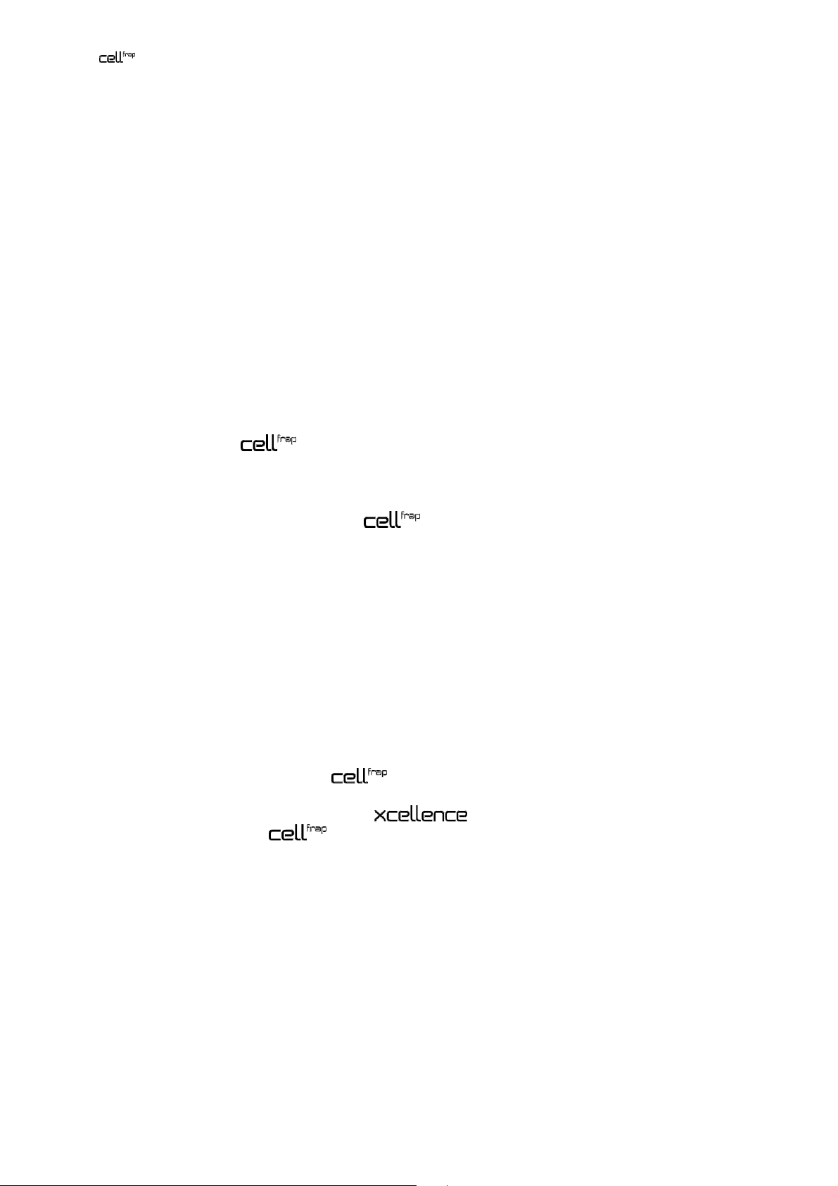
2 Chapter 1 – Introduction
scan head mounted on an IX81
1.1 Abstract
In the following sections you will find a detailed description of the components of
FRAP system, handling and alignment instructions and how to maintain the performance of your FRAP
microscope. Keep in mind that all components are designed to work together with an Olympus
Imaging Station as an integrated system. We strongly discourage taking away or replacing
single components without prior consultation of Olympus Soft Imaging Solutions, most probably it will
impair the performance of the system dramatically. The guarantee will not cover any damages to the
system due to such mishandling. All necessary tools for handling and alignment (except the laser safety
goggles) are part of the product.
If you find any information missing in this manual or you need additional support, please contact your
local Olympus representative.
scanning
Page 9

Manual Chapter 1 –Introduction 3
1.2 General
The MITICO motorized integrated TIRF illumination combiner is compatible with the Olympus
microscope frames IX81S1F-FRAP, IX81S1F-FRAP-ZDC, and IX71S1F-FRAP, as well as a range of
diode laser systems between 405 nm and 700 nm provided that they meet the following requirements:
• Every laser unit must have an input remote-control safety interlock that must be connected to the
central laser emergency stop and which interrupts the laser radiation in case of danger (EN 608251:2003, Sect. 4.4 and 10.2). Furthermore, every laser unit must have a key-activated main power
switch in the sense of EN 60825-1:2003, Sect. 4.5).
• Provided that the laser units can be operated independently they must have their own emission
warning display (audible or visible) (EN 60825-1:2003, Sect. 4.6).
• The combined power of all employed and/or connected laser powers must not exceed 500 mW.
This instructions manual describes the hardware components of the scanning FRAP system,
and their installation. It also explains the software configuration and the use o the system.
It is important to familiarize yourself with the entire system to ensure safety and optimum performance.
We recommend studying this manual as well as the software and hardware manuals of the imaging
system thoroughly before operating the scanning FRAP system. Keep this manual close to the
imaging station for future reference.
The scanning FRAP system meets the CE requirements:
• EN61326 Class A
• EN60825
1.3 Components
The scanning FRAP system consists of the following components:
a Laser shutter hand switch LAS-MC with key with emergency interrupter and key-controlled switch
to maintenance mode
b Laser safety break-out box LAS-BOB
c Laser safety stage cover with translucent laser safety glass that allows following the beam position
d Laser safety ocular shutter
e Manual
The software module for the imaging software is likewise required as well as at least
one laser, favorably a dedicated OSIS FRAP diode laser:
Furthermore the following scanner head and controller shall be used (Rapp Optoelectronic):
Page 10

4 Chapter 1 – Introduction
a illuminator featuring two fiber ports, each with adjustable line focus
b control unit
Page 11

Manual Chapter 2 –
Safety Symbols
5
2 Safety Symbols
The deactivation of the safety systems or the dismantling of different components by the operator is
required in certain operational modes and in case of illumination alignment. As a result the Olympus
scanning FRAP system is to be classified in accordance with EN 60825-1:2003 in laser safety
class 3B and in accordance to EN 954-1:1997 in hazard category 2. Class 3B lasers are medium
power lasers with an output power of up to 500 mW within 400 – 700 nm wavelength. Laser safety
regulations require extensive labeling of all possible apertures where laser radiation might potentially
exit including such apertures that are totally covered except upon partially or totally disassembling the
system.
Page 12
6 Chapter 2 –
Safety Symbols
The following symbols are placed on the Olympus scanning FRAP system. Study the meaning
of the symbols and always use the equipment in the safest possible manner.
General symbols
Symbol Explanation
Indicates the use of a laser beam. Take special care in handling that part.
(See also following chapter)
Carefully read the instructions on the label and the manual before use. Improper use could
result in personal injury to the user and/or damage the equipment.
This symbol indicates separate collection of waste electrical and electronic equipment in the EU
countries.
Do not throw the equipment into the domestic refuse
Please use the return and collection systems available in your country for the disposal of this
product
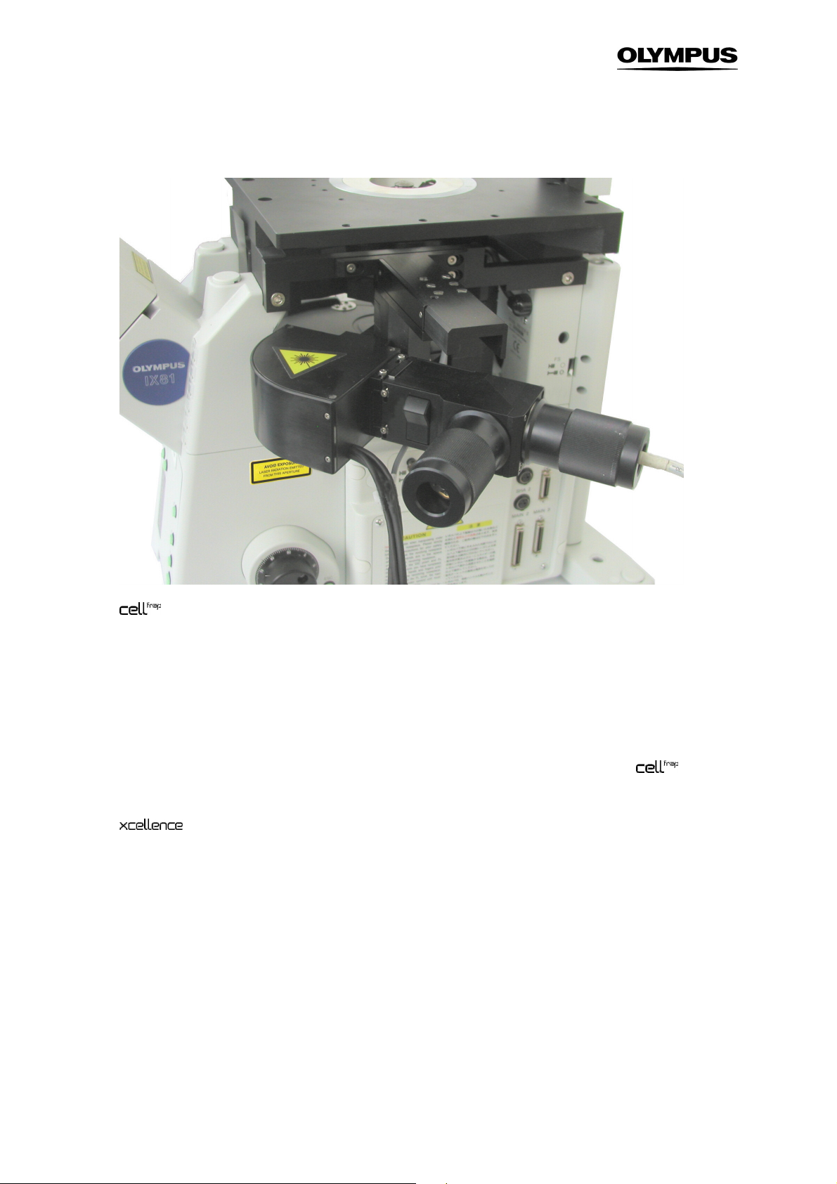
Each laser source must be provided with a danger symbol, a sign with the classification text and a sign
on the beam exit opening. Please ensure that your microscope is labeled as shown in the table below.
For all parts labeled with the following labels special laser precautions must be considered (see
Chapter 4.1, Laser Safety Precautions)!
Laser safety symbols
Symbol Explanation Location
Indicates the use of a laser beam.
Take special care in handling this part.
Laser radiation can cause irreversible
damage to your eyes. Wear adequate
protection before opening this
aperture.
These apertures should be closed
while operating the system. Parts
connected should be dismounted by
trained personal only and when the
laser is turned off.
When system is switched to
maintenance mode laser radiation can
be emitted from this aperture. Be sure
to wear adequate eye protection.
scan head
Microscope frame, right side, left side
near C-mount; see photos 2 and 3.
Laser safety ocular shutter; see photo 4.
Laser safety stage cover; see photo 5.
Labels for the microscope components are included in the shipping list of the Olympus
scanning FRAP system. Please paste them on the microscope upon system installation. If any label is
missing please ask your Olympus representative for additional labels.
Page 13
Manual Chapter 2 –
Safety Symbols
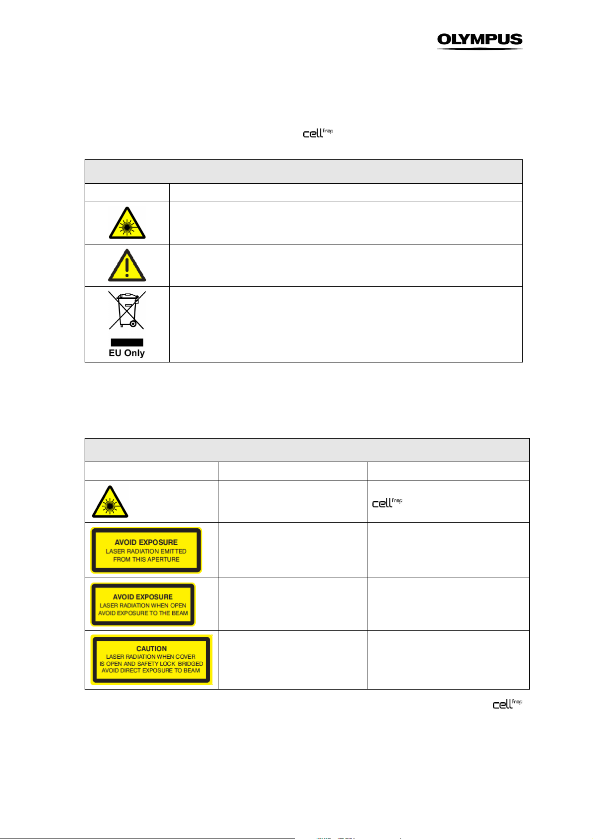
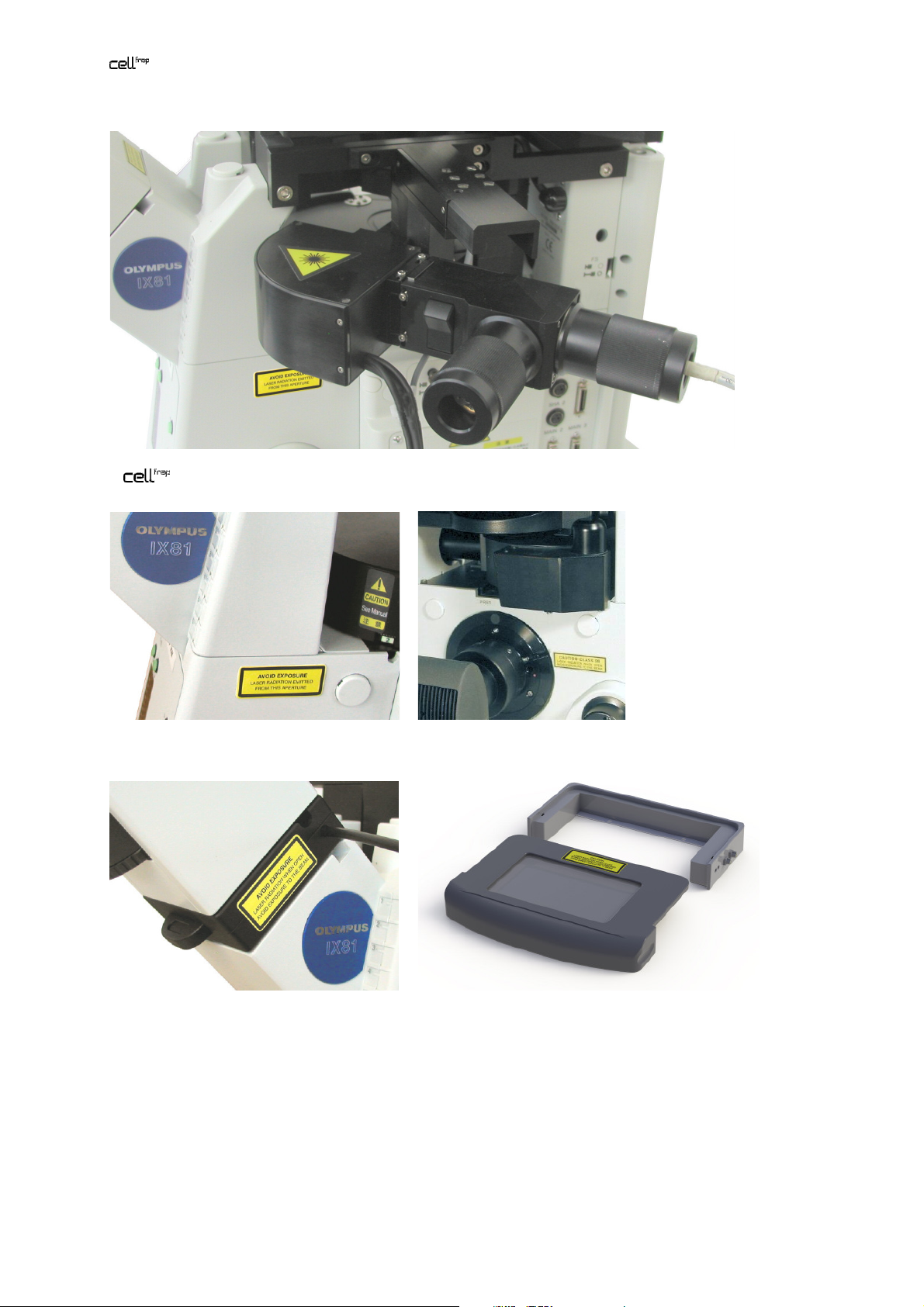
7
1:
scan head
2: microscope frame, right side 3: fluorescence turret and C-mount
4: laser safety ocular shutter 5: laser safety stage cover
Page 14

8 Chapter 2 –
Safety Symbols
Page 15

Illumination Combiner, User Manual Chapter 3 – Safety Precautions and Handling Instructions 9
3 Safety Precautions and Handling
Instructions
The Olympus scanning FRAP system must be used with laser products belonging to the Laser
Safety Class 3B. Class 3B lasers are medium power lasers with an output power of up to 500 mW
within 400 – 700 nm wavelength. The total of the output power of the connected lasers may not exceed
500 mW. Viewing these lasers under direct beam and specular reflection conditions is hazardous. The
diffuse reflection is usually not a hazard except for higher power Class 3B and Class 4 lasers. Normally
the class 3B laser is not a fire hazard. A class 3B laser product may only be used under the control of a
laser safety officer. Before using this product be sure to be familiar with the demanded safety measures
according to EN 60825-1 and the national regulations
3.1 Laser Safety Precautions ............................................................................10
3.2 General Safety Precautions ........................................................................11
Page 16

10 Chapter 3 – Safety Precautions and Handling Instructions
3.1 Laser Safety Precautions
Caution: Control or adjustments using procedures other than those prescribed in this
manual will lead to hazardous laser beam exposure.
To avoid hazardous situations strictly follow the laser safety instructions below.
1. Before operating an Olympus scanning FRAP system check if all devices are
attached correctly and all apertures are closed.
2. The usage of a Class 3B laser is only permitted under the control of a laser safety officer.
3. A Class 3B laser can cause irreversible damage to your eyes. Thus do not stare into the
laser beam or illuminated fiber. Make sure to wear adequate eye protection during operation
of the laser in maintenance mode.
4. Always operate the scanning FRAP system in user mode unless you underwent a
detailed training in operating the system in maintenance mode. Inform your laser safety
officer if you intend to operate the system in maintenance mode. The user mode is the
safest manner to operate the system. Opening the stage cover or the binocular slider will
interrupt the laser beam in this mode.
5. Only trained Olympus service personnel is allowed to perform the installation and alignment
procedures described in the Service Manual.
6. A person in charge with the laser alignment or performing scientific experiments while
operating the laser in maintenance mode must be aware of the safety precautions adequate
to the TIRF microscope setup. He/she is responsible for the safety of any person present in
the room while operating the lasers in maintenance mode.
7. The focused laser beam or any UV light emitted from the microscope nosepiece may injure
the skin through the objective exit lens and through a free nosepiece position. Thus, avoid
exposing the hands to the laser beam when working on the microscope.
8. Do not bend, step on or pull excessively on the laser fibers. This could damage a fiber and
cause hazardous beam leakage. In case of a damaged fiber, switch off the laser immediately
and contact Olympus.
9. Be sure all apertures of your microscope system stay closed or are connected while
operating the laser. A change in camera or any microscope part should be performed only
when the laser is turned off.
10. Never cover the air outlet of the laser to prevent overheating.
Page 17

Illumination Combiner, User Manual Chapter 3 – Safety Precautions and Handling Instructions 11
Direct exposure to the laser light is possible at the following positions:
• The laser system’s housing at the fiber port if the fiber is removed
• The exit of the laser fiber
• The fiber coupling of the widefield illumination system to the scanning FRAP system
• The beam path of the microscope
• Any microscope port, which includes the entrance ports because the laser light can be reflected
within the microscope
• The light output port of the widefield illumination system
• The objective tip or – if no objective is mounted – a free nose piece position
3.2 General Safety Precautions
a. Always use power cords and power supplies provided or approved by Olympus Soft Imaging
Solutions or the manufacturer of your laser system.
b. Provide unimpaired access to the emergency shutter switch at the LAS-MC manual control and to
the main power switches.
c. Only those lasers may be connected that comply the laser safety regulations as described in
Chapter 1.2.
d. Always make sure that the grounding terminal of the laser system and the wall outlet are connected
properly. If the system is not grounded, Olympus Soft Imaging Solutions cannot warrant the
electrical safety and proper performance of the product.
e. Please refer to the user manuals of the respective laser manufacturer for adequate safety
precautions and proper usage.
f. If the equipment is not used as specified in this manual, the safety and performance may be
impaired. In addition the equipment may be damaged and warranty may be lost. Use the
equipment only as outlined in this instruction manual.
Olympus Soft Imaging Solutions GmbH accepts no liability for any health damages caused
by improper use of the lasers and laser related setup!
Page 18

12 Chapter 3 – Safety Precautions and Handling Instructions
Page 19

Manual Chapter 4 –
Overview and Laser Safety Setup 13
4 Overview and Laser Safety
Setup
The following chapter describes all components and interfaces of the Olympus scanning FRAP
system including all laser safety devices and how they are installed and connected.
4.1 Setup Scheme ............................................................................................14
4.2 The Laser Safety Features – Overview and Check .....................................15
4.3 Mounting the Laser Safety Kit .................................................................... 17
4.4 Connecting the Control Unit ....................................................... 18
4.5 Connecting the LAS-BOB Laser Safety Break-out Box .............................19
4.6 The Laser Shutter Manual Control.............................................................. 20
4.7 Key Control ................................................................................................. 21
4.8 The Remote Interlock Connector of the Olympus Soft Imaging Solutions
ODB Laser Systems....................................................................................22
Page 20

14 Chapter 4 –
top view
safety shutters
ocul
ar shutter
Overview and Laser Safety Setup
4.1 Setup Scheme
Laser fibers
scan head
Laser safety
stage cover
Laser safety
IX81,
controller
Scheme of an IX81 microscope with a scanning FRAP system, two lasers and the laser safety equipment.
LAS-BOB
FRAP lasers with
LAS-MC
PC
Connections of the laser safety devices
ODB / RS232 communication connections
TTL trigger connections
FRAP scanner communication connection
Laser fibers
Page 21

Manual Chapter 4 –
ocular shutter
Overview and Laser Safety Setup 15
4.2 The Laser Safety Features – Overview and Check
The laser safety concept of the scanning FRAP system consists of the following modules:
–
A laser safety ocular shutter
–
A laser safety stage cover
–
An emergency interrupter located on the LAS-MC manual control
–
The double-redundant laser safety shutter of Olympus laser systems
–
The LAS-BOB laser safety break-out box that connects all devices electronically
–
A double-redundant laser safety shutter in front of the exit optics of the Olympus Soft Imaging
Solutions lasers
Be sure that all listed components are correctly mounted:
• The laser safety ocular shutter must be placed in the ocular light path as shown below.
Laser safety
• The U-shaped frame of the laser safety stage cover must be fixed on the stage and the stage cover
in place.
The laser safety stage cover must be secured to the microscope stage. If the microscope
stage is not equipped with the necessary pre-drilled holes please make sure that this
modification is performed before using the system. Appendix – Laser Safety Stage Cover
Dimensions provides drawings with all dimension data necessary for such a modification.
Page 22

16 Chapter 4 –
stage cover
stage cover
Overview and Laser Safety Setup
Laser safety
Laser safety
• The 5-pin ocular shutter cable must be connected to the stage cover and this additionally to one of
the 5-pin SAFETY INTERLOCK plugs at the back panel of the control unit.
• The other 5-pin SAFETY INTERLOCK plug at the back panel of the control unit must be
connected to the 5-pin STAGE COVER plug of the LAS-BOB laser safety breakout box.
Check the safety shutter function in user mode in a completely installed FRAP system.
1. Turn the key in the LAS-MC manual control to USER MODE.
2. Switch on the FRAP laser via the software; see Chapter 6.3.1, The FRAP GUI in .
You should observe laser light through the translucent stage cover insert.
3. Open the ocular shutter slider. The indicator diode on the laser safety shutter must become
switched off immediately indicating the closure of the shutter. No laser light should be visible
anymore. Close the slider again.
4. Carefully lift the lid of the stage cover. The indicator diode on the laser safety shutter must
become switched off immediately indicating the closure of the shutter. No laser light should
be visible anymore. Mount the cover again.
The LAS-MC manual control features an emergency interrupter, the red button. If the system is
properly setup and you press the red button,
• The safety shutter of any Olympus Soft Imaging Solutions laser system connected must close
• Any other laser connected to the LAS-BOB break-out box must be switched off entirely
In order to reactivate the system you have to turn the emergency interrupter to release it from the
locked position.
Applying the laser safety emergency interrupter is not a standard test and should only be
tested if changes to the laser configuration and connections have been made. It is only for
emergency use and will cut the power supply of any laser except the Olympus Soft Imaging
Solutions laser systems.
If you have doubts or questions concerning your laser safety devices, contact your laser safety officer.
Page 23

Manual Chapter 4 –
Fixing screws
Interlock
Overview and Laser Safety Setup 17
4.3 Mounting the Laser Safety Kit
1. Remove the ocular from the microscope frame and mount the ocular laser safety shutter
onto the ocular tube (with the cable on the right hand side) and fix it as shown in the photo
below.
2. Mount the ocular back on top of the ocular laser safety shutter and tighten the holding
screw.
3. Mount the U-shaped frame of the laser safety stage cover with the connector plugs pointing
to the right onto the microscope stage fixing it with the two M4x5 fixing screws.
4. Place the lid of the laser safety stage cover on top of the stage frame so that the two pins on
the lid fit into the two holes of the frame that host the interlock switches.
switches
5. Plug the cable of the laser safety ocular shutter with one of the plugs of the laser safety stage
cover.
Page 24

18 Chapter 4 –
5-pin plugs
Transl
u
cent
6. Connect the second plug of the laser safety stage cover with the 5-pin female STAGE
Overview and Laser Safety Setup
COVER plug of the scanning illuminator using the corresponding cable.
insert
4.4 Connecting the Control Unit
The installation of the scanning illuminator is described in detail in the hardware manual. Only
the connection of the cables of the scanning illuminator and the control unit shall be repeated
here. These steps are partly repeated in the following sub-chapters as well.
1. Connect the 5-pin female STAGE COVER plug at the LAS-BOB back panel with one of the
5-pin SAFETY INTERLOCK plugs at the back panel of the control unit using the
corresponding cable.
2. Connect the other 5-pin SAFETY INTERLOCK plug at the back panel of the control
unit with one of the plugs of the laser safety stage cover (and make sure that the second one
is connected to the laser safety ocular shutter).
Page 25

Manual Chapter 4 –
3. Connect the PC RS232 plug at the back panel of the control unit with a serial port of
the system PC.
4. Connect the cable coming from the scan head with the multi-pin plug at the front panel of
the control unit.
5. Connect the TRIGGER IN TTL BNC plug of the control unit with the DIG I/O plug at
the imaging computer front panel that is configured as TTL OUT port in the software; see
Chapter 6.1, System Configuration.
6. Connect the TRIGGER OUT TTL BNC plug of the control unit with the DIG I/O plug at
the imaging computer front panel that is configured as TTL IN port in the software; see
Chapter 6.1, System Configuration.
7. Connect the LASER TTL BNC plug of the control unit with the SHUTTER TTL BNC
plug of the FRAP laser.
Overview and Laser Safety Setup 19
8. Connect the INTERLOCK OUT plug of the control unit with the INTERLOCK plug at
the front panel of an Olympus laser dedicated for FRAP usage using the Cinch cable
provided with it. Connect any other laser in an analogously.
4.5 Connecting the LAS-BOB Laser Safety Break-out
Box
1. Connect the female LAS-MC D-sub 15 plug at the LAS-BOB front panel with the female D-
sub 15 plug of the LAS-MC laser manual control using the corresponding male-male cable.
Page 26

20 Chapter 4 –
Overview and Laser Safety Setup
2. Connect the 5-pin female STAGE COVER plug at the LAS-BOB back panel with one of the
5-pin female SAFETY INTERLOCK plugs at the back panel of the control unit using
the corresponding cable. Make sure the control unit is connected with the laser
safety stage cover and the laser safety ocular shutter.
ÈÈÈÈ
3. Connect the 24 V ÿÿÿÿ–
rrrr
-
-
DC power supply plug with the 24 V DC power supply.
•
C
4. Connect the power supply with a power outlet.
The LAS-BOB additionally features on the front panel:
–
Four INTERLOCK 4 – 3 – 2 – 1 Cinch plugs. These plugs are without function in a
system.
–
Four SHUTTER 4 – 3 – 2 – 1 BNC TTL-OUT plugs. These plugs are without function in a
system.
The LAS-BOB additionally features on the back panel:
–
Two SAFETY SHUTTER 4-pin female plugs. These plugs are without function in a
system.
–
Four DIGITAL I/O 1 – 2 – 3 – 4 BNC TTL-IN. These plugs are without function in a
system.
4.6 The Laser Shutter Manual Control
Connect the female LAS-MC D-sub 15 plug at the LAS-BOB front panel with the female D-sub 15 plug
of the LAS-MC laser manual control using the corresponding male-male cable; see previous chapter.
Note that the LAS-MC manual control cannot be used to open / close the shutter of the
FRAP laser because its TTL In plug is connected to the FRAP controller and not the LASBOB.
The laser shutter manual control features additionally:
–
Four LASER 1, 2, 3, 4 switches. These plugs are without function in a system.
–
A REMOTE switch to set the laser shutters to remote control via external TTL triggers or ODB
device bus communication (typically controlled by a software like ). This switch is
without function in a system.
Page 27

Manual Chapter 4 –
Switches for up to four TTL
-
Button to
Mode lock
with key
Emergency
–
A mode lock with key to allow authorized and trained personnel to switch from standard USER
Overview and Laser Safety Setup 21
MODE to MAINTENANCE (see Chapter 5, Modes of Operation).
–
A red emergency interrupter that closes all safety shutters when pressed.
–
A BINOCULAR button to bridge the laser safety ocular shutter in maintenance mode so that
the specimen can be observed via ocular with laser illumination. This is not a toggle button; it
needs to be kept pressed in order to keep the laser safety shutter open.
Be extremely cautious when bridging the laser safety ocular shutter by pressing the red
button! Be sure that a filter cube that quantitatively blocks reflected laser light is inserted
into the light path. Otherwise hazardous and intense laser light might exit the ocular. Set
the laser to a low intensity with the attenuator before first looking through the ocular.
Switch to toggle between software control
interrupter
bridge laser
safety ocular
shutter
controlled high-speed laser
shutters
4.7 Key Control
The LAS-MC laser manual control has a lock. When the key is removed or when the lock is set to User
mode, lifting the laser safety stage cover or opening the laser safety ocular shutter causes all laser
safety shutters to close.
When set to Maintenance mode, the laser safety stage cover can be lifted and the laser safety ocular
shutter can be opened – when the red button is additionally kept pressed – without causing the laser
safety shutters to close.
The system is a Laser Safety Class 3B product and may be operated in
Maintenance mode by trained and authorized personnel only with the trained laser safety
officer being informed.
Upon leaving the system, the person in charge has to set the LAS-MC laser manual control
to User mode and remove the key to protect the system against unauthorized use.
Page 28

22 Chapter 4 –
Overview and Laser Safety Setup
4.8 The Remote Interlock Connector of the Olympus
Soft Imaging Solutions ODB Laser Systems
An INTERLOCK connector can be found at the front panel of all Olympus Soft Imaging Solutions laser
systems as Class 3B laser products. This remote interlock connector of the dedicated FRAP laser must
be connected to the INTERLOCK OUT plug at the front panel of the control via a Cinch cable.
Interlock connector
Caution. Class 3B laser products not in use must be protected against unauthorized use
by removal of the key from the key control.
In order to comply with laser safety regulations the interlock connectors of non-Olympus Soft Imaging
Solutions laser systems must be connected in the same way.
Page 29

Manual Chapter 5 – Modes of Operation 23
5 Modes of Operation
There are two modes of operation, the user mode and the maintenance mode. In user mode no laser
radiation can exit the system. The maintenance mode is for setting-up and adjusting the
scanning FRAP system. Only trained personnel are allowed to operate the system in maintenance
mode.
5.1 The User Mode ...........................................................................................24
5.2 The Maintenance Mode .............................................................................. 25
5.2.1 Exchanging Microscope or Camera Hardware...........................................25
5.2.2 Access to the Specimen without Deactivating the FRAP System .............. 26
5.2.3 Observing the Specimen Through the Ocular ............................................26
Page 30

24 Chapter 5 – Modes of Operation
5.1 The User Mode
All hardware has to be connected properly to operate the system in User mode. The user mode
ensures that the user can operate the system without being exposed to the laser beam. It is possible to
have full control of the various devices via software or manually. In User mode the system can be used
like a laser of Laser Safety Class 1.
Actions in user mode
Permitted Action Remarks Actions not permitted
Change or manipulation of specimen with laser safety stage
cover lifted
Execution of Experiment Plans in cell^M / cell^R or similar
processes in other imaging software
Live observation via camera, image acquisition in TIRF
conditions
Change of camera settings and switch of microscope
modules as long as no hardware is being dismounted
Change of filters or burner in the illumination system MT10 /
MT20 or other filter switching devices
Change of burner in a fluorescence lamp housing (if used)
Fluorescence and widefield microscopy via ocular
Safety shutter closed
automatically
Observation via binocular
Best with safety shutter
closed
Detaching the optical fiber
Safety shutter closed
automatically
Exchange of microscope
or camera hardware
Detaching the lamp
housing
Operating the scanning FRAP system in User mode:
1. Mount a specimen and search for a region of interest using widefield fluorescence
illumination. Refer to the manual of the imaging system for detailed descriptions.
2. Be sure to have a filter cube with adequate dichroic mirror in the light path.
3. Close the laser safety stage cover and ocular shutter to enable the opening of the laser
safety shutter(s) of the Olympus Soft Imaging System laser systems.
4. Turn on the laser as described in the laser manual. You need to press the START buttons of
the Olympus Soft Imaging System laser systems to open their safety shutters.
5. Open the high-speed laser shutter via software; see Chapter 6, Using the System.
Page 31

Manual Chapter 5 – Modes of Operation 25
To protect your specimen from photo-bleaching, close the laser shutter (by reversing step
5) whenever suitable, even if you interrupt observation only for a short time.
5.2 The Maintenance Mode
Actions in maintenance mode
Permitted Action Remarks Actions not permitted
Exchanging microscope or camera
hardware
Laser adjustment
Specimen manipulation under TIRF
conditions with the stage cover lifted
Specimen observation via ocular
under TIRF conditions
Mounting or exchanging of fiber or
laser
Alignment of fiber at laser exit
Only with LS shutter closed.
Adjustment necessary afterwards.
Refer to safety precautions above. Only
possible with pressed binocular shutter
interlock bridge.
Laser shutters must be closed.
Adjustment necessary afterwards.
Executing experiments with
remote control of the laser
shutters
For details concerning the setup of the hardware, refer to your hardware manuals.
Operating in Maintenance mode is only allowed to persons authorized to operate and
align Class 3B laser products according to the national regulations.
Always wear adequate protection and avoid unnecessary radiation of the laser beam.
While operating the system in maintenance mode, be sure that access to the system is
restricted to authorized persons only.
5.2.1 Exchanging Microscope or Camera Hardware
Before exchanging hardware, always consider the compliance of the new hardware to the requirements
of FRAP microscopy and the laser equipment. Ask your Olympus specialist for advice in case of
uncertainty. The best way to modify a system is with the lasers turned off. After changes affecting the
laser light path through the microscope (e.g., changing an objective or a filter cube) it might be
necessary to realign the laser fiber ports; see the
Hardware Manual.
Page 32

26 Chapter 5 – Modes of Operation
5.2.2 Access to the Specimen without Deactivating the FRAP System
For some applications it is necessary to manipulate the specimen during an experiment. In User mode,
however, the laser safety stage cover has to be in place; otherwise the FRAP system is deactivated
because all laser safety shutters remain closed.
Setting the system to Maintenance mode by authorized and trained personnel allows removing the
laser safety stage cover to gain access to the specimen without causing the laser safety shutters to
close automatically. Thus, lifting the laser safety stage cover might cause exposure to laser irradiation if
the high-speed shutter of any laser system is open.
Check the position of the laser beam through the translucent laser safety stage cover
insert. Be sure to wear adequate laser protection before opening the lid and make sure all
high-speed laser shutters are closed. Shield the specimen with a sheet of paper before
opening a high-speed laser shutter to make sure that the laser beam does not exit the
objective in an unexpected direction.
5.2.3 Observing the Specimen Through the Ocular
Authorized and trained personnel can observe the specimen in Maintenance mode via the ocular
when taking the safety precautions into account.
Before observation via the ocular, make sure to have an adequate filter cube that
quantitatively blocks the laser light inserted into the light path! The use of an inadequate or
damaged dichroic mirror or emission filter can lead to intense, hazardous laser light exiting
the ocular. This laser light can irreversibly damage your eyes!
Never change optical elements (filter, dichroic mirror, objective etc.) while observing the
specimen by eye. The switch of optical elements can lead to reflections of laser light into
the ocular.
1. Activate the Maintenance mode by turning the key on the LAS-MC laser manual control to
the MAINTENANCE position.
2. Open the ocular shutter by pulling the slider out all the way. The laser safety shutter will close
automatically.
Page 33

Manual Chapter 5 – Modes of Operation 27
Laser safety ocular
shutter, slider OUT
3. Hold a sheet of paper in front of the eyepieces.
4. Open the laser safety shutters of the lasers by pressing the red ocular safety interlock bridge
button of the LAS-MC manual control. Check the sheet of paper to control the light intensity
emitting from the ocular pieces before looking through the eyepiece.
Control or adjustment procedures other than those described will lead to hazardous laser
beam exposure!
Page 34

28 Chapter 5 – Modes of Operation
Page 35

Manual Chapter 6 – Operating the System 29
6 Operating the System
The scanning FRAP system and the Olympus Soft Imaging Solutions laser systems are fully
integrated in the imaging software This chapter describes the configuration and usage of
the scanning FRAP system.
6.1 System Configuration .................................................................................30
6.2 The FRAP GUI in ............................................................... 31
6.3
6.3.1 FRAP Experiments...................................................................................... 33
6.3.2 Fire On Click ...............................................................................................36
6.3.3 Pattern Bleaching – Fluorescence Speckle Microscopy ............................37
in the Experiment Manager ........................................................ 33
Page 36

30 Chapter 6 – Operating the System
6.1 System Configuration
1. Start the ObsConfig software to configure the excitation filters
2. Make sure that the FRAP lasers are configured on pages MicroscopeLaser as described
in the laser manual.
3. Go to page MicroscopeFRAP.
In case this page is not available right-click on OBS System Configuration (top left), open the
Components context menu and activate FRAP.
4. Click FRAP available to activate the unit.
5. Select the PC serial port (COM port) connected with the control unit. Once selected
correctly (and with the control unit powered up) the Connected field turns green.
6. Select the Laser from the shortlist. Mind that this laser will not be eligible as light source for
the Image Types.
7. TTL Synchronization, DIG I/O -> FRAP Trigger IN. Select from the short list the TTL OUT
connection at the imaging PC front panel that is connected with the TRIGGER IN
of the
control unit.
Page 37

Manual Chapter 6 – Operating the System 31
8. TTL Synchronization, FRAP Trigger OUT -> DIG I/O. Select from the short list the TTL IN
connection at the imaging PC front panel that is connected with the TRIGGER
OUT of the control unit.
9. Exit the software with OK.
6.2 The FRAP GUI in
This interface is mainly meant for calibration purpose and for opening and closing the FRAP laser
shutter. The use of in the context of "true" FRAP experiments is explained in the next Chapter
6.3, in the Experiment Manager.
Control
Disconnected / Connected. The box turns green and reads Connected if the software detects the
presence of the controller via the serial connection. The status can be update by clicking the
Update button on the right side.
Laser on/off. Use this toggle button to turn the laser connected to the (and configured
accordingly in OBS System Configuration) on or off (respectively, open or close its shutter).
Center spot. Click this button to move the scanner mirrors to their central position. This will set the
laser spot to the central image position if the system is aligned correctly.
Objective. This field displays the currently active objective. The calibration needs to be performed for
each objective that is to be used for the FRAP experiments. The currently used objective is listed here.
Calibrated. The status box turns green once the system is calibrated.
Page 38

32 Chapter 6 – Operating the System
The calibration is valid only for the objective in place during the calibration. A later manual
change of the objective does not cause a change of the status display. However, a
recalibration is required.
Set spot size. Click here to open the Enter spotsize window. Enter the spot Diameter in pixel and
confirm with OK. The default value is set in dependence of objective magnification and NA as well as
wavelength and pixel size. It presumes a perfectly focused laser. If the laser is defocused – which may
well be done on purpose – the spot needs to be imaged and measured to determine its actual size.
Laser intensity. Use the slider to attenuate the laser intensity.
Calibrate. Click here to start the calibration routine. The camera starts Live image acquisition, starts
laser emission and the Calibrate point #1 window opens.
The calibration procedure consists of two parts. First, the scanner positions corresponding to the four
corners of the camera image are determined. Afterwards, in the so-called Fine calibration, a total of 16
scanner positions distributed over the camera field of view are referenced.
The calibration is always done without binning on a full frame.
You may Adjust circle diameter by using the slide so that the red circle matches the laser spot in size.
Mind that the laser spot size in the image not just depends on the laser focus but also on the
Brightness adjustment settings in the Camera control window; see Chapter 4.2, Camera Control, in
the software manual. It is often useful to set the Max. intensity clipping to 0 % here.
Calibrate point #1. In the top left corner of the Live image a red circle is marked. Use the arrow
(cursor) keys to move the laser spot to this red circle. It is not required to do this with utmost precision
Page 39

Manual Chapter 6 – Operating the System 33
because the software will detect the bright spot when it is reasonably close. Increase the step size by
keeping the Ctrl key pressed while using the arrow key. Keep the Shift key pressed to reduce it.
Once the spot is at the position of the red circle click Next to terminate the first calibration step. The
red circle will now appear at the top right corner of the Live image and the Calibrate point #2 window
opens. Repeat the above procedure here and subsequently for point #3 and point #4 in the bottom left
and right corners, respectively.
Once the fourth corner has been determined the Start of fine calibration window opens upon clicking
Next. In this second part of the calibration routine the laser spot will move to 16 positions and needs to
be moved on with the mouse cursor on and confirmed.
Click OK. The Fine calibration window opens and the laser spot will be positioned at the top left
corner of the Live image. Move the tip of the mouse cursor over the laser spot and press the Enter key
to confirm.
The laser spot will move to the second position at top half-left. Again, move the tip of the mouse cursor
over the laser spot and press the Enter key to confirm.
Once all 16 positions have been confirmed the Calibration is finished. The calibration for the objective
in use is stored and does not have to be repeated for this objective unless the camera is rotated
relative to the C-mount.
6.3 in the Experiment Manager
6.3.1 FRAP Experiments
FRAP command icon
Types of experiments
Advanced. This selection gives access to all variable parameters.
In order to simplify the interface partly preconfigured experiments can be selected. Here different sets
of parameters are deactivated.
FRAP (Fluorescence Recovery After Photobleaching). This is the basic experiment where one or more
ROIs are bleached once. Bleaching is always done Once at Cycle 10 and the acquisition always done
Page 40

34 Chapter 6 – Operating the System
after bleaching. The Acquire radio buttons and the Condition parameters are deactivated. Manual
start during experiment is not possible.
FLIP (Fluorescence Loss In Photobleaching). In this experiment the ROIs are bleached in Every Cycle
and acquisition always done after bleaching. The Acquire radio buttons and the Condition
parameters are deactivated. Manual start during experiment is not possible.
Photoconversion. This experiment is identical to FRAP with the exception that the acquisition always
done while bleaching. The Acquire radio buttons and the Condition parameters are deactivated.
Manual start during experiment is not possible.
Use ROIs from image. Select the image containing the ROIs to be bleached from the shortlist. It lists
only images that contain ROIs.
Number of scan cycles. Set here the number of times the ROIs are to be scanned in each (Time
Loop) Cycle. The default is 1 but one may decide to scan several times, for example with reduced laser
intensity. By doing so the influence of timing differences between the bleaching of the fist positions of a
ROI and the last positions is reduced.
Calculate Timing. Click here so that the software calculates how long the scan will take. The value is
displayed next to the button. By changing the Number of scan cycles you may thus determine how
long the bleaching will last.
Acquire after photobleaching. With this option the following image acquisition is synchronized with
the end of the ROI scan(s). The laser spot will not be visible in this image. This option is automatically
selected in case of FRAP and FLIP experiments.
Acquire while photobleaching. Here image acquisition and ROI scan start simultaneously. The trace
of the scanning laser spot will be visible in the image. This option is automatically selected in case of
Photoconversion experiments.
Page 41

Manual Chapter 6 – Operating the System 35
Manual start during experiment. This check box is active only if the Advanced experiment is
selected. If the option is checked the command icon shows a hand symbol. The command icon turns
into a button.
FRAP command icon with Manual start symbol
What will happen?
After the start of the experiment the FRAP command icon will simply be ignored until clicked by the
user. Clicking is possible at any time and will immediately start the ROI scan independently of the
position of the command icon in the experiment plan and independently of the current advance of the
experiment.
Preview
Live view while bleaching button
Click here to start a live preview simultaneously with a laser scanning cycle. The scanning laser spot
will be visible in the beginning.
Live view after bleaching button
Click here to start a laser scanning cycle with a live preview following immediately after the scan is
finished.
Snapshot after bleaching button
Click here to start a laser scanning cycle with a single snapshot following immediately after the scan is
finished.
Stop FRAP preview button
Click here to stop the Live view.
Extended
Scan speed. This determines the duration of a scan and thus the time that the laser rests at each
position during the scan. Set the scan speed by use of the slider or by typing a value. The speed is
expressed as frequency in Hz. The default value is 10 kHz (10.000 Hz).
FRAP inside ROI. Mind that the ROIs drawn in the image will be "filled" with positions of the laser spot
and thus the form of the ROIs will only be approximated. This parameter defines how much the outer
laser spot positions may overlap with the ROI borders. Set the percentage by use of the slider or by
typing a value. The default value is 100%.
Page 42

36 Chapter 6 – Operating the System
Edge accuracy. The FRAP scanner controller composes the ROIs to be scanned out of subrectangles. The smaller the sub-rectangles are the higher is the resulting correspondence with the
ROIs. Set the accuracy by use of the slider or by typing a value. The default value is 5 pixels, the range
2 pixels.
Default. Click here to reset the defaults.
Condition
These options are active only if the Advanced experiment is chosen.
Enable. Check here to use the options. Otherwise the command is executed in each Time loop cycle.
Once at … Cycle. This option is used in typical FRAP experiments. Set the cycle number when the
FRAP scan is to be executed.
Every Nth … Cycle. This option is used in typical FLIP experiments. Set the interval between the
bleaching scan if time loop cycles with and without scan shall alternate.
6.3.2 Fire On Click
Fire On Click command icon
This command icon allows applying a laser flash at will during the experiment and at any spot within
the image. It can be repeated as often as wanted. This allows carrying out bleaching or photoactivation
experiments where it is not known before hand when and where an object to be exposed to the laser
will appear.
The system will Fire after a Click the next time the Fire On Click command is being cycled through in
the experiment plan. Let's take the following Experiment plan; see below. The Fire On Click command
Page 43

Manual Chapter 6 – Operating the System 37
is the first one within each cycle. At one point in time during a certain cycle a Click is being applied.
The Fire will only be carried out as soon as the next cycle is being started. Thus, while the manual Click
is unsynchronized, of course, the Fire initialized by the FARP controller is not.
The software "burns" a marker into the image following a "Fire" each time.
Bleach duration. Set here the duration of the laser flash.
Acquire after fire. With this option the following image acquisition is synchronized with the end of the
ROI scan(s). The laser spot will not be visible in this image.
Acquire while fire. Here image acquisition and ROI scan start simultaneously. The trace of the
scanning laser spot will be visible in the image.
Multiple points. This option allows to select several spots in the image with left mouse clicks– the
software internally generates a list of XY positions – and flash them all subsequently as fast as possible
upon a right click.
Interpolate lines. This option is available only if option Multiple points is checked. Activate this option
to do "line bleaching" instead of bleaching individual spots. Apply a series of (left) Clicks on certain
points of a structure. The display will show a polygon line instead of spots. Start the Fire with a right (!)
mouse click. The scanner will move the laser beam along the line – and not switch it off between the
spots as in the usual mode.
Preview: Live view while bleaching, Live view after bleaching, Stop FRAP preview. See previous
chapter for details.
6.3.3 Pattern Bleaching – Fluorescence Speckle Microscopy
Pattern Bleaching command icon
In this experiment the laser spot positions are set with predefined gaps in between. The resulting
pattern of bleached or photoactivated spot makes movements of structures relative to each other quite
visible.
Most parameters and options are explained in detail in Chapter 6.3.1, FRAP Experiments.
Pattern spacing
Spot distance factor. Set the value here. The Spot size is being multiplied with the Spot distance
factor In order to define a certain distance between each spot of the pattern.
Remember that the Spot size is defined via Set spot size in the FRAP window with the default value
presuming a perfectly focused laser; see Chapter 6.2, The FRAP GUI in . The pattern is most
regular if rectangular ROIs are being used. Other types of ROIs need to be composed of sub-rectangle
as described for the command Edge accuracy in Chapter 6.3.1, FRAP Experiments. Here the pattern
of spots will be more irregular.
Page 44

38 Chapter 6 – Operating the System
Page 45

Manual Chapter 7 – Specifications, Technical data 39
7 Appendix
This chapter lists specifications and technical data of the system.
7.1 Laser Safety Stage Cover Dimensions .......................................................40
Page 46

40 Chapter 7 –Specifications, Technical Data
7.1 Laser Safety Stage Cover Dimensions
The laser safety stage cover must be secured to the microscope stage with the M4x5 screws provided.
If the microscope stage does not have the necessary pre-drilled holes, this simple modification must be
performed before using the system. The following drawings show all dimensions necessary for such a
modification.
Page 47

Manual Chapter 7 – Specifications, Technical data 41
Page 48

Page 49

Page 50

Page 51

®
OLYMPUS EUROPA HOLDING GMBH
Postfach 10 49 08, 20034, Hamburg, Germany
Printed in Germany 2010 09 M 001
 Loading...